1
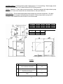
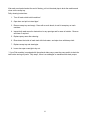
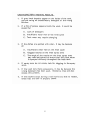
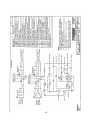
OWNER’S
MANUAL
BLAKESLEE
Division of Blako Inc.
UNDERCOUNTER DISHWASHER
UC-21
I.R.S.
INTEGRATED RECIRCULATING SYSTEM DESIGN
1844 South Laramie Avenue
Chicago, IL 60804
Phone (708) 656-0660
Fax (708) 656-0017
www.blakesleeinc.com
[email protected]
1149 Bellamy Road North Unit 19
Scarborough, Ontario Canada M1H1H7
Phone (416) 751-2625
Fax (416) 751-8539
Date of Installation
Serial No.
Model No.
USA
Limited Warranty
Your new Blakeslee dishwashing machine is warranted for one year from date of installation shown above
against defective materials and workmanship. If any defects are found within the warranty period; parts, and
labor involved with their replacement will be covered free of charge. Service must be performed by a Blakeslee
authorized service agency. All labor to be performed during regular working hours. Overtime premium will be
charged to the customer. All warranty parts are shipped by surface transportation. If other means of
transportation is requested the customer is required to pay the premium. This warranty does not apply to
damages resulting from errors in installation on the part of other contractors, nor does it apply to machines
which have been subject to accident, misuse, or abuse. It is understood that Blakeslee’s warranty obligation
with respect to machines located outside of the United States or located in the state of Alaska is limited to the
furnishing of replacement parts only. In the state of Hawaii, repair labor is provided free of charge; travel time
and expenses paid by the customer. On the island of Oahu, repair labor, travel time and expenses are provided
free of charge. This is the entire and only warranty of Blakeslee. We neither assume nor authorize anyone else
to assume for us any other obligation or liability in connection with Blakeslee Machines.
• In no case can this warranty exceed eighteen (18) months from the date of shipment from our plant at
Chicago, Illinois
Items NOT Covered Under Warranty
1. Replacing Fuses or resetting Overloads.
Replacing a blown fuse or resetting an open overload breaker is a very simple procedure and is the owner’s
responsibility. If the machine continues to blow fuses or open the overload breaker, contact your nearest
authorized Blakeslee Service Center.
2. Adjusting Tank Heats.
Heat adjustments are covered in The Owners Manual and must be adjusted depending upon desired results.
3. Proper Loading of Dishes.
It is important that the machine owner’s personnel observe the instructions outlined in The Owners Manual.
4. Cleaning Drain Valves.
Foreign articles lodged in the drain valve seat should be removed as a part of the normal daily cleaning.
5. Cleaning Rinse or Wash Nozzles and Line Strainers.
Keeping a dishwasher clean and removing obstructions from the nozzles and line strainers will be a periodic
function of the machine owner’s personnel. The cleaning periods will vary depending upon impurities in the
water supply and cleanliness of the washing operation.
6. Final Rinse Water.
Most frequent of all complaints in any dishwashing machine is that of poor final rinse. It is the responsibility of
the owner to provide 180 to 195 degree (plus) water at 15-25 lb. flow pressure through clean unobstructed water
lines. If the machine has a factory equipped final rinse water booster, the owner must supply the booster with a
minimum of 140 degree temperature water.
INDEX
Page
1
3
5
Section 1 Installation Instructions *
Section II Operating Instructions
Section III Cleaning Instructions
Section IV Troubleshooting
Section V Optional Equipment
Section VI Illustrated Parts List
SPECIFICATIONS
Construction:
Body of stainless steel construction throughout.
MACHINE INSTALLATON DATA:
Electrical:
Wash System:
Top and bottom counter rotating spray arms.
Rinse system:
Top and bottom counter rotating spray arms.
Recirculating System:
Gallons per minute
Horsepower
180
1
Wash Tank Capacity:
6.0 gallons
Volts
220
220
Phase
1 (4 wire)
3 (5 wire)
Load Amps
48.6
27.0
Water Supply:
Inlet Temperature
Inlet Pressure *
Inlet Size
Inlet Flow
Drain Size
Water Consumption
140° F
20 psi
½” Hose
6gpm
1 ½” OD Hose
30.5 gpm
Wash and Rinse Cycle
Water Heating:
An electric immersion heater rated at 9.0 KW
heats both the wash and rinse water.
Control:
Automatic wash/rinse cycle control.
Thermostatically controlled rinse temperature
Wash Time
105 seconds
Dwell Time
5 seconds
Rinse Time
12 seconds
Total Cycle
120 seconds
* Inlet pressure should be measured at the
connection point of the dish machine.
SECTION I INSTALLATION
The Model UC21 is suitable for both under the counter and free standing installations. Access is
required to both the sides and rear of the machine for service and maintenance. Therefore, all
connections should be made with flexible hoses and conduit to ensure that access can be achieved.
SHIPMENT CHECKOUT & UNCRATING
Unit is shipped with standard commercial packing, should any damage be observed on visual
inspection of the crate; notify the freight carrier immediately, as hidden damage may exist.
No special equipment is required to uncrate the unit. However care should be taken to ensure that no
damage is caused by the implements used in uncrating the machinery.
Level the machine by adjusting legs as necessary, while maintaining counter clearance dimensions.
NOTE: If machine is not leveled properly door will not close correctly
If door rubs on right
side adjust right leg
down or left leg up
If door rubs on left
side adjust left leg
down or right leg up
FIGURE 1
INSTALLER WARNING
To protect Booster Heating Element
Do not turn on electrical power supply to dishwasher until water supply has first been connected and
you are ready to proceed with actual test operation of the machine.
-1-
WATER SUPPLY: Connect incoming water supply hose to ½” I.D. hose fitting. Water supply source
must be able to provide 140°F water minimum at 20 PSI flow pressure.
DRAIN: Connect 1 ½” drain tube to waste connection. Machines equipped with optional drain pump
will have a ¾” hose to be inserted into an elevated drain or sink (see section 5).
ELECTRICAL: Check machine data plate before making any electrical connections. All supply
connections must correspond with data plate information. Check pumps rotation, pump turns
clockwise when viewed from rear of motor; if not reverse leads.
MODEL
UC-21
UC-21T
UC-21XT
A
33 ¼”
39 ¼”
45 ¼”
B
37 ¼”
43 ¼”
49 ¼”
Dimensions A & B are ± 1”
DIM. FROM
FLOOR
1
2
2” LEG
6” LEG
4”
4 ½”
8”
8 ½”
FIGURE 2
Size of Connection
1
140° Hot Water Connection
1/2”
2
(Check Data Plate Requirements to Correspond
with Correct Power Supply)
1”
3
Drain
1 ½”
Electrical Connection
-2-
C
12”
18”
24”
D
15 ½”
21 ½”
27 ½”
SECTION II OPERATION
DO NOT ATTEMPT TO OPERATE WITHOUT WASH
TANK BEING PROPERLY FILLED, DRY ROTATION
WILL DAMAGE PUMP SEALS AND VOID WARRANTY
1. Ensure that all spray arms spin freely and that scrap tray and standpipe are properly installed.
NOTE: There is no stand pipe on machines equipped with an optional drain pump.
2. Depress ON/OFF main switch to “ON” position. Switch light will indicate power is on. Close
door.
3. Depress and hold START/FILL switch in the “FILL” position for 50 seconds or until water can
be heard flowing down the drain.
4. If detergent is fed manually, prep full tank of fresh water with 3 oz. of a low suds commercial
detergent, then 1 oz. per each cycle there after. Increase or decrease detergent rate based on
results.
5. Insert rack with properly pre-scrapped and pre-flushed ware.
6. Close door, depress and hold START/FILL switch for 1 second in the “START” position.
Lighted switch will indicate machine is operating.
7. Cycle is completed when START/FILL switch indicator light turns off.
8. Open door and remove rack of cleaned ware. IMPORTANT do not leave rack sitting on open
door.
9. Washing operation is completed
START/FILL SWITCH
MAIN ON/OFF SWITCH
DRAIN PUMP SWITCH
(OPTIONAL)
FINAL RINSE
TEMPERATURE GAUGE
FINAL RINSE
PRESSURE GAUGE
WASH TANK
TEMPERATURE GAUGE
ADJUSTABLE LEG
FIGURE 3
-3-
Observe the following instructions to obtain maximum performance from the dishwashing machine.
1. Whenever possible, instruct bus boys or wait staff to stack the soiled dishes according to sizes
as they are brought to the soiled dish table.
2. Remove by hand, rubber scraper, or pre-washing as much food particles left on the dishes as
possible. This will reduce pollution of water, insure the cleanest possible wash water and
lower detergent costs.
3. Rack dishes in appropriate rack as indicated in figure 4. When placing silverware in
combination rack; you should be able to see many holes in the bottom of the rack after it is
loaded. Dishes and all “flat” china should be stacked in the multi-purpose racks so that they
lean back with the face of soiled surface of the dish exposed to the upper spray. Glasses,
cups, bowls and other “deep” dishes should be placed face down in the combination racks.
Remember, whenever possible it is a good practice to have your bus boys or waitresses place
cups, glasses and bowls directly in the combination rack. Do not overcrowd or overload the
racks as the wash and rinse waters must reach all surfaces to obtain clean ware.
4. Scrape and rack more dishes and insert the racks of soiled ware into the machine.
5. Clean ware must be taken out of the racks and the empty racks removed from the clean dish
table and returned to the soiled dish table for reloading. Do not let dish racks pile up on the
clean dish table until they hit the end of the dish table as this subjects the conveyor to
unnecessary strain. Let the washed and rinsed dishes remain in the racks for a minute or so
until they have had a chance to drain and self dry. If the dishes are removed from the racks to
soon, they will not be dry.
6. Continually check wash and rinse temperatures.
7. Be sure enough detergent is being added to the wash water to keep it at an effective strength
if an automatic dispenser is not being used.
8. Detergents should be used according to the detergent manufacturer’s recommendations. Their
representative knows the capabilities of their detergents and can determine the proper
treatment of your water for proper use with their product. The wash water must be kept at an
effective strength to obtain good washing results. Use a good detergent. Never use a foaming
soap or soap flakes. Ask your local detergent man for his help and heed his advice.
FIGURE 4
MULTI-PURPOSE RACK
PART NO. W-0-16428
COMBINATION RACK
PART NO. W-0-16429
-4-
SECTION III MAINTENANCE & CLEANING
Maintenance:
Motor: No lubrication required
Pump: No lubrication required
Wash Arms:
a. Wash arms, upper and lower, should turn freely and continue turning for a few seconds after
being whirled by hand.
b. If the scrap screen is not properly in place, obstructions may clog the wash arm nozzles. The
wash arms are easily removed for cleaning.
c. To remove the upper & lower wash arms, turn the individual arms clockwise and remove.
d. Push the obstruction into the arm and flush out.
e. To reassemble push arm in hole and turn counter clockwise.
Rinse Arms:
a. The rinse arm nozzles will need frequent cleaning if your water contains lime or other solids.
b. To remove the rinse arms you should first remove the wash arm assemblies.
c. On upper wash arm assembly remove knob and lower assembly. On lower remove knob and
lift assembly. NOTE: Take care not to lose bushings.
d. Remove rinse arms by taking set screw out of top and pulling out arm.
e. Push the obstruction into the arm and flush out.
f. To reassemble push arm in hole and align screw hole with hole in top, insert and tighten set
screw.
g. Put assemblies back in and install knob. Check to make sure assemblies turn freely.
Wash Arm
Knob
Rinse Arm
Standpipe
Drain Outlet
FIGURE 5
-5--5-
After each meal period and at the end of the day, pull out the stand pipe to drain the machine and
clean out the scrap tray.
Daily cleaning instructions:
1. Turn off main switch to dish machine*.
2. Open door and pull out stand pipe*.
3. Remove scrap tray and empty. Clean with a scrub brush, do not hit scrap tray on trash
container.
4. Inspect both wash arms for obstructions in any openings and for ease of rotation. Remove
and clean if required.
5. Replace spray arms after cleaning.
6. Rinse down the inside of wash tank with fresh water, and wipe down with damp cloth.
7. Replace scrap tray and stand pipe.
8. Leave door open overnight to dry out.
* If your Dish machine is equipped with the optional drain pump; press the pump switch to drain the
tank before turning off power. Skip step 2, there is no standpipe on machines with drain pumps.
-6-
-7-
SECTION IV PARTS
PROTECT YOUR EQUIPMENT
USE GENUINE BLAKESLEE PARTS
-8-
FIGURE 1. RECIRCULATING SYSTEM
-9-
FIGURE 1. RECIRCULATING SYSTEM
-10-
FIGURE 2. SPRAY ARMS & MANIFOLDS
-11-
FIGURE 2. SPRAY ARMS & MANIFOLDS
-12-
FIGURE 3. ELECTRICAL ASSEMBLY
-13-
FIGURE 3. ELECTRICAL ASSEMBLY
-14-
FIGURE 4. BODY ASSEMBLY
-15-
FIGURE 4. BODY ASSEMBLY
-16-
FIGURE 4. BODY ASSEMBLY
-17-
-18-
BLAKESLEE
BLAKESLEE