1
MegaPower® CPU
ADMPCPU
Administrator’s Guide
8200-0421-03 G
MegaPower CPU
®
Administrator’s Guide
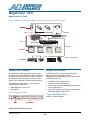
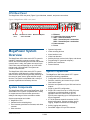
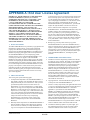
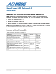
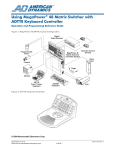
Figure 1. MegaPower 3200 Video-Matrix Closed-Circuit Television (CCTV) System
Cameras
Data
Video
ADDL*
Protocol
Devices
Matrix
Switcher Bay
Video
MegaPower CPU
Data
Monitors
*ADDL = AD Data Line
Keyboards
About the Product
About this Guide
The MegaPower CPU (Central Processing Unit) is
the control unit for the MegaPower 3200 video-matrix
closed-circuit television (CCTV) system. It enables
the setup and control of cameras, monitors, users,
alarms, video recording, and data communications.
This Administrator’s Guide provides information
about setting up and programming the
MegaPower 3200 video-matrix CCTV system. Other
related documents are:
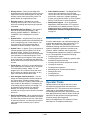
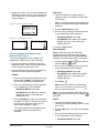
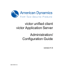
The MegaPower CPU (Figure 2) consists of the
following major components:
• MPU (Multiple Purpose Unit)
• Port Module
Figure 2. MegaPower CPU
• Installation Guide, 8200-0421-01
• Operator’s Guide, 8200-0421-02
• CPU Activity Log Client Installation and Operation
Guide, 8200-0421-09
• AD1024 S3 System Setup Software Installation &
Operating Manual, 8000-1821-01
If you need assistance...
Contact Technical Support.
MPU
Port Module
© 2009 Sensormatic Electronics Corp.
MEGAPOWER CPU
ADMINISTRATOR’S GUIDE
8200-0421-03, REV. G
1 of 82
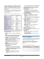
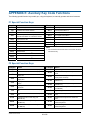
Contents
®
MegaPower CPU.................................................... 1
About the Product..................................................... 1
About this Guide....................................................... 1
MegaPower 3200 Video-Matrix CCTV System
(Dual CPU).......................................................... 4
MegaPower CPU Front Panel.................................. 4
CPU Rear Panel....................................................... 5
MegaPower System Overview ................................. 5
System Components ................................................ 5
System Capabilities.................................................. 5
Compatible System Keyboards................................ 6
System Features ...................................................... 6
Administrator Tasks.................................................. 7
Operator Tasks......................................................... 7
Initializing the System............................................... 8
Understanding the Screen Icons......................... 8
Direct Connection................................................ 8
Ethernet Network Connection ............................. 9
Firewall Setup ................................................... 12
Read Cycle........................................................ 12
Write Cycle........................................................ 13
Error Message Example.................................... 13
Installing EASY CPU .............................................. 13
System Requirements....................................... 13
Beginning the Installation .................................. 13
Starting EASY CPU................................................ 16
Configuring Preferences ................................... 16
Viewing Configuration File Properties............... 17
Saving Data on the Hard Drive ......................... 17
Retrieving Configuration Data........................... 18
Adding a User Login............................................... 21
Logging in Users for CPU Read/Write Access....... 22
Programming the MegaPower CPU....................... 23
EASY CPU Main Screen Overview........................ 23
Dropdown Menus .............................................. 23
Explore Menu .................................................... 24
Status Bar ......................................................... 24
Settings Window Display Area.......................... 24
Checking the System Status .................................. 24
Monitor Status ........................................................ 24
Camera Status ....................................................... 25
Passive Hot Switch Status ..................................... 25
Error Log Status ..................................................... 26
Configuring the System .......................................... 27
Setting System Options.......................................... 27
Setting System Date and Time .............................. 28
MEGAPOWER CPU
ADMINISTRATOR’S GUIDE
Setting the Date and Time Using the Dialog
Box............................................................... 28
Setting the Date and Time Using the
Keyboard ..................................................... 29
Setting Port Configurations .................................... 30
Configuring the Dome/PTZ Device Direct
Connection........................................................ 30
Configuring Switching ............................................ 32
Creating Salvos...................................................... 32
Deleting Salvos or Alarm Contacts ................... 34
Creating Tours ....................................................... 34
Deleting Tours or Cameras............................... 35
Event Timers .......................................................... 35
Event Timers – Alarm Tables ........................... 35
Event Timer – Tours ......................................... 36
Configuring Alarms................................................. 37
Setting Up Alarm Monitors ..................................... 37
Adding Monitor Definitions................................ 37
Contact Arming ................................................. 39
Event Timers..................................................... 39
Creating Alarm Monitor/ Contact Tables................ 40
Alarm Messages .................................................... 42
Email Messages..................................................... 42
Defining System Devices ....................................... 42
Defining Cameras .................................................. 42
Adding Camera Definitions ............................... 43
Adding and Deleting Calling Contacts to
Cameras ...................................................... 44
Associating Salvo Callups to Cameras............. 45
Defining Keyboards................................................ 46
Adding Keyboard Definitions ............................ 46
Configuring Keyboard/User Keyboards and
Priorities ............................................................ 48
Defining the Keyboard/User Keyboards
Configuration ............................................... 48
Configuring the Keyboard/User Priority
Settings........................................................ 49
Defining Satellite Sites ........................................... 50
Controlling Access with Partitions.......................... 50
Associating Cameras to Monitors .......................... 50
Adding Camera Definitions ............................... 51
Editing Camera Definitions ............................... 52
Changing Calling Contacts ............................... 52
Removing Calling Contacts .............................. 53
Associating Keyboards to Cameras....................... 53
Adding Keyboard Definitions ............................ 54
Editing Keyboard Definitions............................. 54
Deleting Keyboard Definitions .......................... 54
Adding Cameras to Keyboards......................... 54
8200-0421-03, REV. G
2 of 82
Removing Monitors or Satellite Sites Access
from Keyboards............................................ 55
Associating Keyboards to Monitors........................ 55
Adding Keyboard Definitions............................. 55
Editing Keyboard Definitions............................. 56
Deleting Keyboard Definitions........................... 56
Adding Monitor Access to Keyboards ............... 56
Adding Monitors to Keyboards.......................... 56
Removing Monitors from Keyboards................. 57
Associating Keyboards to Satellites ....................... 57
Adding Keyboard Definitions............................. 57
Editing Keyboard Definitions............................. 58
Deleting Keyboard Definitions........................... 58
Adding Site Access to Keyboards..................... 58
Adding Satellite Sites to Keyboards.................. 59
Removing Satellite Sites from Keyboards......... 59
Associating Monitors to Cameras .......................... 59
Adding Monitor Definitions ................................ 60
Adding a Range of Cameras............................. 61
Contact Arming ................................................. 61
Event Timers ..................................................... 62
Performing a Ping Test........................................... 62
Declarations ........................................................... 63
APPENDIX A: End User License Agreement......... 64
APPENDIX B: MegaPower CPU System Defaults 66
APPENDIX C: MegaPower CPU Front Panel
LCD Menu Structure ......................................... 67
APPENDIX D: Port Number Assignments ............. 68
APPENDIX E: Auxiliary Key Code Functions......... 69
F1 Special Function Keys ................................. 69
F2 Special Function Keys ................................. 69
MEGAPOWER CPU
ADMINISTRATOR’S GUIDE
APPENDIX F: Configuring Video Loss Detection .. 71
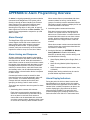
APPENDIX G: Alarm Programming Overview ....... 73
Alarm Receipt ................................................... 73
Alarm Arming and Response............................ 73
Alarm Display Indicators ................................... 73
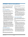
APPENDIX H: Monitor Arming Methods ................ 74
Alarm Display Method....................................... 74
Alarm Queuing Method ..................................... 74
Alarm Clearance Method .................................. 74
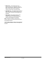
APPENDIX I: Monitor Arming Codes ..................... 76
Single Display, Sequence Queuing .................. 76
Single Display, Hold Queuing ........................... 76
Block Display, Sequence Queuing ................... 76
Block Display, Hold Queuing ............................ 77
Dual Display, Hold and Sequence Queuing ..... 77
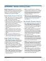
APPENDIX J: Alarm Arming Notes........................ 78
Associating Alarms with Camera Salvos .......... 78
Associating Alarms with Monitor Blocks ........... 78
Monitor Block Queuing for Single Cameras ..... 78
Monitor Block Queuing for Camera Salvos ...... 78
Auxiliary and Preset Alarm Call-ups ................. 78
Wired Alarm Contact Sets ................................ 78
APPENDIX K: Satellite Configuration Overview .... 79
Setting Up Satellite Sites .................................. 79
Satellite Site Connections................................. 80
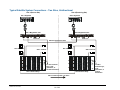
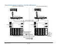
Typical Satellite System Connections – Two
Sites, Unidirectional ..................................... 81
Typical Satellite System Connections – Two
Sites, Bidirectional ....................................... 82
8200-0421-03, REV. G
3 of 82
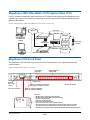
MegaPower 3200 Video-Matrix CCTV System (Dual CPU)
Figure 3 illustrates a MegaPower 3200 video-matrix CCTV system with an optional second MegaPower CPU
installed and a computer connected for programming the system using the EASY (Enhanced Administration
SYstem) CPU software.
Figure 3. MegaPower 3200 Video-Matrix CCTV system (dual CPU)
Video Input
Ethernet
Data Line
Video Bays
Programming PC
with EASY CPU
software
MegaPower CPU
Keyboards
Multiple
RS-232 Ports
Monitors
Domes and
Cameras
Video Input
Data Line
nd
Optional 2
Video Bays
MegaPower CPU
Intellex
MegaPower CPU Front Panel
The MegaPower CPU front panel (Figure 4) provides information about the unit’s operating condition and
communications.
Figure 4. MegaPower CPU—front panel
COM port RS-232
activity LEDs
Port module
soft select
Power reset
Flashing
blue = CPU
running
Red = fault condition
Solid green = Ethernet connectivity
Flashing green = Ethernet activity
Amber on = Ethernet 100BaseT
Amber off = Ethernet 10BaseT
Rx
MEGAPOWER CPU
ADMINISTRATOR’S GUIDE
AD data line activity
Tx
LCD Icons:
– Blinking heart = System operating properly
– Blinking broken heart = MPU not communicating
– Up arrow = Selected CPU
– Down arrow = Backup CPU
– Clear circle = Normal operation
– Dark circle inside outer circle = CPU fault (error)
– Circle with one arrow = Single passive hot switch ribbon cable connected
– Two opposing arrows = Dual passive hot switch ribbon cable connected
– Rx/Tx levels = Peak and current level RS-232 and AD data line activity indicators
8200-0421-03, REV. G
4 of 82
CPU Rear Panel
The MegaPower CPU rear panel (Figure 5) provides data, network, and power connections.
Figure 5. MegaPower CPU—rear panel
a.
AD data
lines
The MegaPower 3200 video-matrix CCTV system is
capable of managing cameras, monitors, alarm
events, and video recording at both local and satellite
(remote) sites. Locally, the system can control up to
3,200 video cameras displayed on up to 256 video
monitors with 128 keyboards. The system can
include 30 satellite sites.
The MegaPower 3200 video-matrix CCTV system
can respond to 4,096 alarms by calling cameras to
alarm monitors and performing auxiliary switching for
the control of gates, doors, lights and other output
devices. The system is compatible with a variety of
operator keyboards and accessory devices.
System Components
The MegaPower CPU controls the MegaPower 3200
video-matrix CCTV system. It operates with a variety
of components and communication protocols to
satisfy a wide range of video surveillance needs.
System components can include:
• MegaPower CPU
• Camera/monitor switching bays
• Fixed cameras, pan/tilt/zoom cameras, and dome
cameras
• Video monitors
MEGAPOWER CPU
ADMINISTRATOR’S GUIDE
d.
e.
a. Ethernet
b. Composite video image capture
c. SW1 – Video termination
SW2 – SensorNet port 2 termination
SW3 – SensorNet port 1 termination
d. Data connector
e. Power
AD data line switch RS-232 COM ports
select and LED
MegaPower System
Overview
b. c.
•
•
•
•
•
•
•
•
Operator keyboards
Video recording devices
Alarm interface units
Video loss detection
Auxiliary devices such as locks, lights, and alarms
Programming PC (personal computer)
Satellite site connections
Protocol devices
System Capabilities
The MegaPower 3200 video-matrix CCTV system
provides the following capabilities:
• Configurable via PC based software
• Selection, switching, and control of up to 3,200
local camera inputs
• Selection and operation of up to 256 local monitor
outputs
• Single or dual CPU configuration
• Single CPU control from up to 16 RS-232 ports
supporting up to 64 keyboards via AD port
expander. Dual CPU control from up to 32
RS-232 ports supporting up to 128 keyboards via
AD port expander.
• IP 10/100 Ethernet network connection for PC
based configuration, firmware updates, activity
logging, snapshot and Email text messaging
• Activity logging and reporting
• SensorNet support for up to 508 cameras
8200-0421-03, REV. G
5 of 82
• Support for up to 30 satellite systems
• Control up to 96,000 remote cameras
• Control up to 38,528 remote cameras (full
crosspoint connection) to 256 monitors
• Response to up to 4,096 alarms
• Supports up to 64 Tours
• Supports up to 64 Salvos
• Pseudo camera numbering of up to 9,999
• Support for recording devices
• Multilingual (English, French, German, Italian,
Portuguese, Spanish)
MegaPower CPU. The system can respond to up
to 4,096 local alarm contacts.
• Camera Alarm Programming – Each alarm
contact can be programmed to call up a local
camera, Salvo, Preset camera scene and
auxiliary action.
• External Control Inputs – RS-232 ports allow
local and remote control via keyboards,
computers, or other compatible devices. You can
configure each port for alarm inputs and
upload/download of system setup data. You also
can expand each local port via an AD port
expander.
Compatible System Keyboards
MegaPower CPU video switching and control
capabilities are provided by American Dynamics
keyboards. These capabilities are “monitor oriented”
in that a keyboard controls only those functions
associated with the monitor under control of that
keyboard.
The MegaPower CPU is compatible with the
following keyboards:
•
•
•
•
AD2078A
AD2079
AD2088
AD2089 (see note)
•
•
•
•
ADCC0200
ADCC0300
ADCC1100
ADTTE
You can arm each monitor used for alarm
displays for different display and clearance
methods.
For step-by-step instructions on using these
keyboards with your MegaPower 3200 video-matrix
CCTV system, refer to the appropriate keyboard
manual.
• Monitor Tours – A Monitor Tour is a temporary
sequence of cameras programmed from a local
keyboard for an individual monitor. A Monitor Tour
can contain up to 64 local cameras, each with a
unique dwell time.
System Features
The following are the MegaPower 3200 video-matrix
CCTV system features:
• Activity Logging – The system can log
keyboard, alarm, and system configuration activity
via a connected PC running Activity Logging
Client Software. The data is stored in a format
compatible with popular database sorting,
formatting, and reporting software. Refer to the
CPU Activity Log Client Installation and Operation
Guide, 8200-0421-09, for more information.
MEGAPOWER CPU
ADMINISTRATOR’S GUIDE
• Memory Retention – All local user-programmed
data is stored in flash memory. The data stored
includes date/time, input identification, system
Tours and Salvos, event timers, port
configurations, system partitioning and alarm
programming information.
• Monitor Alarm Programming – Each alarm
contact can be programmed to display its
associated camera on specific monitors. You can
program separate alarm contact-to-monitor
associations for call up by Event Timers.
Note: When the AD2089 keyboard is connected
directly to the MegaPower CPU, the DVR (digital
video recorder) functions are not supported.
• Alarm Response – An alarm is a signal
generated by an external device (such as an
alarm contact or sensor) connected to a local
• Input Identification – The MegaPower CPU
provides on-screen identification of all video
inputs. On-screen identification of local and
remote cameras includes the camera input
number, programmable title, status, and the date
and time.
• Partitioning – Programmable partitioning restricts
access to specific local and satellite system
resources.
• Passcode Log On and Log Off – Operator
passcode entry allows only authorized personnel
to operate the system. The passcode entry
system allows a maximum of 500 users with
separate passcodes.
• PC System Setup Software – EASY CPU is a
PC-based software application package that
provides programming and storage of all
MegaPower CPU system setup information. The
software allows you to read and write setup data
to and from the MegaPower CPU.
8200-0421-03, REV. G
6 of 82
• Priority Access – Priority levels assigned to
keyboards and users allow higher priority users to
capture and lock out cameras (pan, tilt, lens and
auxiliary control) from lower priority users. The
system allows up to eight priority levels.
• Recorder control – Operators can control
recording devices (DVR, VCR or other current
and future recording devices) through keyboard
commands.
• Satellite Site Support – Up to 30 individual
MegaPower 3200 video-matrix CCTV systems
can be linked into a satellite network. For more
detailed information on satellite systems, go to
APPENDIX K: Satellite Configuration Overview
on page 79.
• Selectable Date/Time Display – The system’s
date can be programmed to display in the
following formats: MM/DD/YY, DD/MM/YY or
YY/MM/DD. Time is displayed in a 24-hour
format.
• System Salvos – A System Salvo is a group of
local cameras programmed for simultaneous callup to a contiguous group of local monitors. You
can program up to 64 system salvos with a
maximum of sixteen cameras in each Salvo.
• System Tours – A System Tour is a sequence of
cameras programmed from EASY CPU for an
individual monitor. System Tours cannot be
altered by keyboard commands and are therefore
more permanent in nature than Monitor Tours.
You can create up to 64 System Tours, each with
up to 64 cameras. You determine the dwell time,
Preset camera scene and auxiliary action for each
camera.
• Timed Events – An Event is a user-defined time
slot programmed for automatic call up of System
Tours and Alarm Contact Tables. You can
program up to 35 local Event Timers with each
set for call ups at a specific time of day, on any
days of the week and week after week.
• User-Assigned Camera Numbers – You can
assign user-defined pseudo camera numbers to
any camera input. Pseudo numbers identify
cameras by function or location, rather than by its
input number on the switcher. For example, you
could assign pseudo numbers 101 through 110
for cameras on the first floor of a multi-floor
building, 201 through 210 for second floor
cameras, 301 through 310 for third floor cameras,
and so on.
• Video Loss Detection – When equipped with the
optional Video Loss Detector module, the system
can detect the presence or loss of a video signal
for each local camera. You determine the sync or
video signal level at which a loss of video is
detected.
MEGAPOWER CPU
ADMINISTRATOR’S GUIDE
• Video Switcher Control – The MegaPower CPU
controls the video switching of all local and
remote cameras to all local monitors. Switching is
performed in response to operator keyboard
request or by automatic action via Tours, System
Salvos, Timed Events, or Alarm Response.
Administrator Tasks
A system administrator is an individual assigned to
manage the MegaPower 3200 video-matrix CCTV
system. This person often participates in preinstallation planning and should be familiar with the
system’s capabilities, equipment, camera inputs,
monitors, satellite locations, and programming.
The administrator prepares the system for operators
to use. This preparation includes the following:
• Configuring the system
• Creating operator IDs, scheduling operator shifts,
and determining access levels
• Creating camera names and pseudo numbers
• Creating site numbers
• Creating alarm responses
• Maintaining a list of alarms and auxiliaries
• Setting Event times
• Creating Salvos
• Creating system Tours
Operator Tasks
Operators perform the day-to-day task of video
surveillance using keyboards connected to the
MegaPower CPU. They select and control cameras,
create and run automated camera actions,
acknowledge alarm activities, adjust monitors, and
take appropriate action based on what is observed.
Operators can also perform limited programming
functions through their keyboards.
Refer to the MegaPower CPU Operator’s Guide,
8200-0421-02, for additional information.
8200-0421-03, REV. G
7 of 82
•
•
•
•
Initializing the System
There are two methods for initializing the
MegaPower 3200 video-matrix CCTV system:
• Direct connection of a PC to the CPU using either
an RS-232 port or the Ethernet port
• Ethernet connection through an Ethernet network
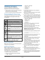
Understanding the Screen Icons
Indicates by constantly blinking on and off
that the system is operating properly.
Indicates the MPU is not communicating.
Indicates the CPU that is currently active
(selected).
Indicates, in a dual CPU system, the CPU
that is currently on backup (standby) status.
This CPU still receives data while in this
condition.
Indicates that the system is operating
properly.
Indicates that an error (fault) has occurred.
An error message is displayed with this
icon.
Indicates that a CPU is connected to itself
using a single passive hot switch ribbon
cable. No dual CPU installation is installed
or connected.
Indicates that both CPUs are connected
together in a dual system using dual
passive hot switch ribbon cables.
Direct Connection
Note: Ensure the keyboard you are using is properly
configured for your installation.
Note: S3 software should be used only to copy an
existing configuration from an AD1024 CPU to a
MegaPower CPU. If you are creating a completely
new configuration, use the EASY CPU software.
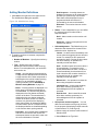
To initialize the system, do the following:
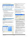
3. Open the S3 program. When the Transfer System
dialog appears, click X to close it.
5. Click COMM Port Parameters in this menu, and in
the PC Port dialog, set the parameters as follows:
• Baud rate = 4800 bps
• Parity = none
• Data bits = 8
• Stop bits = 1
Description
RS-232 Port (S3 Software)
2. Connect the PC RS-232 port to the configured
AD1024 RS-232 port.
4. In the S3 window, click the PC Utility button at the
bottom of the left column. A popup menu appears.
The following icons can be seen on your CPU LCD
screen. Some icons only appear under certain
circumstances.
Icon
Baud rate = 4800 bps
Parity = none
Data bits = 8
Stop bits = 1
6. Click the green check (9) button to accept the
setting, and then close the dialog.
7. Click the PC Utility button, and then click Video
Matrix Switch in the popup menu.
8. Set the Video Matrix Switch Selection field to
AD1024, and set Disk Drive field to C:. The Video
Matrix Switch Directory opens.
9. In the Directory field, type the following file name:
C:\Program files\Sensormatic\S3\A
D1024\MPCPU.
10. Click inside any other field to create the file. This
is the file that stores the existing AD1024
configuration.
11. Click the X to close the dialog, and then click the
X to close the COM Port dialog. The Transfer
System dialog opens.
12. Upload the configuration by clicking all the white
check boxes in the Transfer System dialog, and
then click the up arrow at the bottom of the
Transfer System dialog.
13. Wait for the uploading process to complete, and
then click the X to close the Transfer System
dialog.
14. Disconnect the AD1024 CPU end of the PC
RS-232 cable from the AD1024, and connect it to
any port on the new MegaPower CPU.
15. Click the S3 PC Utility in the left column of the S3
window, and then click COM Port Parameters in
the popup menu.
1. Configure an AD1024 RS-232 port as follows:
• Type = Terminal
MEGAPOWER CPU
ADMINISTRATOR’S GUIDE
8200-0421-03, REV. G
8 of 82
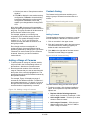
16. Set the PC Com port for the following:
• Baud Rate = 1200 bps
• Parity = none
• Data bits = 8
• Stop bits = 1
To initialize the system with a CPU connected
directly to a PC via the Ethernet port, do the
following:
17. Click the green check (9) button to accept the
settings, and then click the X to close the dialog.
2. Switch on the PC, and ensure EASY CPU is
installed and operational on the PC. Refer to the
sections starting on page 13 for installing, starting,
and programming instructions.
1. Connect the CPU directly to the PC via an
Ethernet cable.
Note: You can decrease the file transfer time by
changing both the PC and the MegaPower CPU
COM ports to 4800bps.
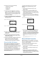
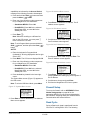
18. Power up the MegaPower CPU. The LCD screen
displays the AD Welcome Screen, followed by the
CPU Status screen.
3. Switch on the CPU. The LCD screen displays the
AD Welcome Screen, followed by the CPU Status
screen.
Figure 8. AD welcome screen
Figure 6. AD welcome screen
Figure 9. CPU status screen
Figure 7. CPU status screen
4. If the PC is connected directly to the MegaPower
CPU, and the PC and MegaPower CPU are not
connected to a network, the default IP address,
192.168.0.1, can remain at the IP address. Before
attempting a configuration download, ensure that
the IP address is configured in the following
folder:
19. Click the S3 PC Utility in the left column of the S3
window, and then click Transfer System in the
popup menu.
20. Click all the white check boxes in the Transfer
System dialog, and then click the down arrow at
the bottom of the dialog.
21. Wait for the download to complete, and then click
the X to close the Transfer System dialog.
Note: The LCD screen does not display a
confirmation that the configuration is complete.
When configuring the MegaPower CPU with EASY
CPU software, use an Ethernet cross cable to
connect the PC via its Ethernet port to the CPU. The
CPU also can be connected to a LAN and accessed
by any PC running EASY CPU on the LAN.
MEGAPOWER CPU
ADMINISTRATOR’S GUIDE
Ethernet Network Connection
Note: Depending on your installation, you can use
either an IP address assigned by the network DHCP
server or a static IP address.
Ethernet Port (EASY CPU Software)
The default IP address on a new MegaPower CPU
from the factory is 192.168.0.1. The IP address can
only be changed with a keyboard connected to an
RS-232 port on the CPU.
EZ CPU\MPCPU\System\Options\CPU
Addresses\CPU # 1.
To initialize the system that is installed using the
Ethernet protocol, do the following:
1. Connect the CPU to the Ethernet network via an
Ethernet cable.
2. Connect the PC to the Ethernet network via an
Ethernet cable.
3. Switch on the PC, and ensure EASY CPU is
installed and operational on the PC. Refer to the
sections starting on page 13 for installing, starting,
and programming instructions.
8200-0421-03, REV. G
9 of 82
4. Switch on the CPU. The LCD screen displays the
AD Welcome Screen (Figure 10), followed by the
CPU Status screen, two examples of which are
shown in Figure 11.
ADCC1100:
a. Place the keyboard in Program Mode by
clicking the tab in the middle of the lower part
of the screen).
Note: To display and enter Program Mode, you
must insert a Smartcard that has administrator
privileges.
Figure 10. AD welcome screen
b. Press the Matrix Menus softkey.
c. Enter one of the following number sequences
for your MegaPower CPU installation:
○ Standalone MPCPU: Enter 100.
Figure 11. CPU status screen
○ Dual MPCPU: Enter 100 for the selected
MegaPower CPU, or enter 101 for the
Standby MP CPU.
d. Press the Enter softkey.
or
ADCC0200/0300:
Notes: In RS–232 mode, the ADCC0200
keyboard does not have matrix menu access
capabilities as indicated by the Access Denied
message if the following procedure is attempted.
Using an IP Address Assigned by the
Network DHCP Server
To set up the MegaPower CPU to obtain an IP
address from a DHCP server, do the following:
a. Press and hold the Shift ( ) button and then
) button.
press the Menu (
1. Connect a keyboard to an RS-232 port on the
MegaPower CPU. Ensure the baud rates match
for the keyboard and CPU port in use.
b. Enter one of the following number sequences
for your MegaPower CPU installation:
2. Use the following instructions to provide the key
sequences for each supported keyboard:
○ Standalone MPCPU: Enter 100.
○ Dual MPCPU: Enter 100 for the selected
MegaPower CPU, or enter 101 for the
Standby MP CPU.
AD2088:
a. Place the keyboard in Menu Mode by turning
the keyswitch to MENU. The Camera field
LED on the keyboard should display P6.
c. Press Enter ( ).
b. Enter one of the following number sequences
for your MegaPower CPU installation:
○ Standalone MPCPU: Enter 100.
Note: Whenever scrolling to a different line
item on the LCD screen, you must press
twice to select the new item.
Note: To exit Program Mode, press and hold the
Shift ( ) button, and then press the Clear (
)
button.
○ Dual MPCPU: Enter 100 for the selected
MegaPower CPU, or enter 101 for the
Standby MP CPU.
c. Press the ENTER key, which is located above
the joystick. “ENTER” is stenciled on the front
face of the key; the top of the key may be
labeled either PRESET or SHOT.
The Camera field LED on the keyboard will
only display 7P if the selected CPU is
accessed.
ADTTE:
a. Place the keyboard in Program Mode
(indicated by –P being displayed at the far right
of the LCD).
b. Press the Menu key. The LCD screen displays
P6 - M.
c. Enter one of the following number sequences
for your MegaPower CPU installation:
○ Standalone MPCPU: Enter 100
MEGAPOWER CPU
ADMINISTRATOR’S GUIDE
8200-0421-03, REV. G
10 of 82
7. Press Enter to choose Enable.
○ Dual MPCPU: Enter 100 for the selected
MegaPower CPU, or enter 101 for the
Standby MP CPU.
8. Exit from the MegaPower CPU menu system.
d. Press the Ack key located in the lower right
corner.
Using a Static IP Address
To set up the MegaPower CPU for a static IP
address:
The System Menu appears on the LCD screen
(Figure 12).
1. Connect a keyboard to an RS-232 port on the
MegaPower CPU. Ensure the baud rates match
for the keyboard and CPU port in use.
Note: To exit the LCD Menu Mode, press the
Menu key.
2. Use the following instructions to provide the key
sequences for each supported keyboard:
Figure 12. System Menu screen
AD2088:
a. Place the keyboard in Menu Mode by turning
the keyswitch to MENU. The CAMERA LEDs
on the keyboard display P6.
3. Press Enter to choose Addressing. The Address
Menu screen appears.
b. Enter one of the following number sequences
for your MegaPower CPU installation:
○ Standalone MPCPU: Enter 100.
Figure 13. Address Menu screen
○ Dual MPCPU: Enter 100 for the selected
MegaPower CPU, or enter 101 for the
Standby MP CPU.
c. Press the ENTER key, which is located above
the joystick. “ENTER” is stenciled on the front
face of the key; the top of the key may be
labeled either PRESET or SHOT.
4. Press Enter to choose IP Address. The IP
Address screen appears.
The CAMERA LEDs on the keyboard will only
display 7P if the selected CPU is accessed.
Figure 14. IP Address screen
ADCC1100:
a. Place the keyboard in Program Mode by
pressing its softkey.
5. Scroll down to Set IP Addr and press Enter. The
Set IP Address screen appears.
Figure 15. Set IP Address screen
Note: To display and enter Program Mode, you
must insert a Smartcard that has administrator
privileges.
b. Press the Matrix Menus softkey.
c. Enter one of the following number sequences
for your MegaPower CPU installation:
○ Standalone MPCPU: Enter 100.
○ Dual MPCPU: Enter 100 for the selected
MegaPower CPU, or enter 101 for the
Standby MP CPU.
6. Scroll down to DHCP and press Enter. The
DHCP Setting screen appears.
d. Press the Enter softkey.
Figure 16. DHCP Setting screen
ADCC0200/0300:
Notes: In RS–232 mode, the ADCC0200
keyboard does not have matrix menu access
MEGAPOWER CPU
ADMINISTRATOR’S GUIDE
8200-0421-03, REV. G
11 of 82
capabilities as indicated by the Access Denied
message if the following procedure is attempted.
Figure 18. Address Menu screen
a. Press and hold the Shift ( ) button and then
) button.
press the Menu (
b. Enter one of the following number sequences
for your MegaPower CPU installation:
○ Standalone MPCPU: Enter 100.
○ Dual MPCPU: Enter 100 for the selected
MegaPower CPU, or enter 101 for the
Standby MP CPU.
4. Press Enter to choose the IP Address. The IP
Address screen appears.
Figure 19. IP Address screen
c. Press Enter ( ).
Note: Whenever scrolling to a different line
item on the LCD screen, you must press
twice to select the new item.
5. Scroll down to Set IP Addr and press Enter. The
Set IP Address screen appears.
Note: To exit Program Mode, press and hold the
Shift ( ) button, and then press the Clear (
)
button.
Figure 20. Set IP Address screen
ADTTE:
a. Place the keyboard in Program Mode
(indicated by –P being displayed at the far right
of the LCD).
b. Press Menu. The LCD screen displays P6 - M.
6. Scroll down to Set IP Addr and press Enter. The
Enter IP Address screen appears.
c. Enter one of the following number sequences
for your MegaPower CPU installation:
Figure 21. Enter IP Address screen
○ Standalone MPCPU: Enter 100
○ Dual MPCPU: Enter 100 for the selected
MegaPower CPU, or enter 101 for the
Standby MP CPU.
d. Press the Ack key located in the lower right
corner.
The System Menu screen (Figure 17) appears on
the LCD screen.
Note: To exit the LCD Menu Mode, press Menu.
Figure 17. System Menu screen
7. Press Enter, and then type the IP address
pressing Enter twice after typing each segment of
the IP address.
8. Scroll down to Accept and press Enter.
9. Exit from the MegaPower CPU menu system.
Firewall Setup
3. Press Enter to choose Addressing. The Address
Menu screen appears.
To set up the firewall, refer to APPENDIX D: Port
Number Assignments on page 68 for the
appropriate MPCPU IP port source and destination
port numbers. Assigning these port numbers allows
communication with external devices.
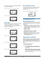
Read Cycle
During a Read cycle, data is transferred from the
CPU to a PC running EASY CPU. The following
MEGAPOWER CPU
ADMINISTRATOR’S GUIDE
8200-0421-03, REV. G
12 of 82
screens show the sequence of operations that take
place during a Read cycle.
Error Message Example
The following screen shows an example of an error
message that can appear when an abnormal
condition occurs.
Figure 22. File transfer in progress screen
Figure 28. Error message screen example
E1032
Rem KB Switch
Figure 23. File transfer completed screen
Remote KB SW Equal
Installing EASY CPU
System Requirements
Write Cycle
During a Write cycle, data is transferred to the CPU
from a PC running EASY CPU. The following
screens show the sequence of operations that take
place during a Write cycle.
Figure 24. File transfer in progress screen
The following are the minimum system requirements
for installing and operating the EASY CPU software
application:
• Computer: PC-compatible computer with 600
MHz Intel® Pentium® III microprocessor or greater
• Hard Drive Space: 300MB (100MB if .NET 1.1 is
already installed)
• Memory: 128MB
• Network Card: 10BaseT or 100BaseT
• Video: SVGA with 16MB video RAM
• Monitor: 800 x 600 pixel resolution, 16-bit color
Figure 25. Receiving file saving screen
• Operating System: Microsoft® Windows® XP,
Microsoft Windows Vista
Beginning the Installation
Figure 26. Received file saved screen
Note: The following procedure explains the steps for
a first-time installation. If EASY CPU is resident on
your computer, installing subsequent versions will
cause a different sequence of installation screens to
appear.
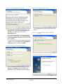
To begin installing EASY CPU:
1. Do one of the following:
• If you have the EASY CPU CD, insert it into
the computer. It should automatically load the
install program.
Figure 27. File transfer completed screen
MEGAPOWER CPU
ADMINISTRATOR’S GUIDE
Note: If the installation program does not load
automatically, manually start it by navigating to
My Computer, and then double-click on the CD
drive unit to start autorun.
8200-0421-03, REV. G
13 of 82
• If you are downloading EASY CPU from a web
site or server to the computer, save the zip file
to a folder you have chosen, and then unzip
the file in that folder. Next, double-click on the
file, Setup.exe, to begin installation.
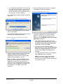
4. When the following screen (Figure 31) appears,
click Next to continue the installation.
Figure 31. Wizard Welcome screen
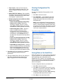
The Choose Setup Language dialog box appears
(Figure 29).
Figure 29. Choose Setup Language dialog
2. Select the desired language from the dropdown
menu, and click OK.
The InstallShield Wizard operating system version
checking screen appears (Figure 30).
5. When the License Agreement screen (Figure 32
on page 15) appears, do one of the following:
Note: To view the License Agreement in your
language, go to APPENDIX A: End User License
Agreement on page 64.
Figure 30. Operating System Version Check
screen
• After reading the license agreement, if you
accept the license agreement terms, click the I
accept the terms in the license agreement
radio button, and then click Next.
• If you do not want to accept the license
agreement terms, click the I do not accept the
terms in the license agreement radio button,
and then click Cancel. The installation will
terminate.
3. A series of screens appear during the installation
progress. Respond to the prompts as the
installation progresses. When the prompt, OK,
appears during installation, click on it.
Note: If you want to end the installation at any
point before the installation has completed, click
Cancel in a screen where this choice is not
grayed out. You will be prompted to confirm that
you want to end the installation. Click Yes to end
the installation, or click No to continue the
installation.
MEGAPOWER CPU
ADMINISTRATOR’S GUIDE
If you want to go back a step in the installation,
click < Back whenever it is appears.
Note: You can print a copy of the License
Agreement by clicking Print in this screen;
however, you must have a printer connected to
your system to do this.
8200-0421-03, REV. G
14 of 82
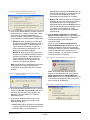
Figure 32. License Agreement screen
Figure 34. Ready to Install screen
6. In the Customer Information screen (Figure 33),
type your user name in the User Name field, and
then type your organization name in the
Organization field.
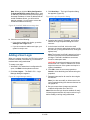
The following screens (Figure 35 and Figure 36)
appear.
Figure 35. Installing EASY CPU Configurator
screen
If you want to install EASY CPU so that anyone
can access the application, click the Anyone who
uses this computer (all users) radio button, and
then click Next.
If you want to limit access to the application to just
yourself, click on the Only for me (organization
name) radio button, and then click Next.
Figure 33. Customer Information screen
Figure 36. Installation Complete screen
7. When the Ready to Install screen (Figure 34)
appears, click Install to begin the EASY CPU
installation, or click Cancel to end the installation.
8. Continue to the next section, Starting EASY CPU.
MEGAPOWER CPU
ADMINISTRATOR’S GUIDE
8200-0421-03, REV. G
15 of 82
Figure 38. EASY CPU Main screen
Starting EASY CPU
Figure 37. Installation Complete screen
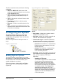
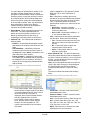
Configuring Preferences
Once EASY CPU is started, do the following:
To start EASY CPU, do one of the following:
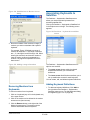
1. Click Edit, and then click Preferences in the
dropdown menu bar. The Preferences dialog box
appears (Figure 39).
• If you want to start EASY CPU immediately
following completion of the installation, click the
Launch EASY CPU Configurator checkbox in
the preceding screen (Figure 37), and then click
Finish.
Figure 39. Configurator Preferences dialog
• If you do not want to start EASY CPU immediately
following completion of the installation, leave the
Launch EASY CPU Configurator checkbox
blank, and click Finish.
If you choose to wait to start EASY CPU, then
locate the MegaPower 3200 file > EASY CPU
Configurator file > Configurator.exe, and then
either double-click the file name to start the
application, or use the Start Menu.
In either case, EASY CPU starts and the Main
Screen appears (Figure 38). Easy CPU will start
in the language selected during installation.
MEGAPOWER CPU
ADMINISTRATOR’S GUIDE
2. To complete the configuration preferences, enter
the following information:
• Language – From the Language dropdown,
select the appropriate language. EASY CPU
supports the following languages:
− English
− French
− German
− Italian
− Portuguese
− Spanish
− Korean
− Chinese
8200-0421-03, REV. G
16 of 82
• Time Format – Select a Time Format by
clicking either Standard Format (12-hr., a.m.
and p.m. display) or Military Format (24-hr.
display).
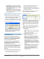
Viewing Configuration File
Properties
• Default MPCPU IP Address –Set the default
IP address used for write/read operations if no
IP address is specified as CPU A and CPU B
in the System – Options screen.
• Default Config File Save and Backup Paths
used for File => Write
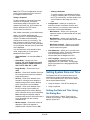
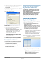
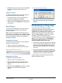
To view the configuration file properties, do the
following:
1. Click File on the main screen.
2. Click Properties… in the dropdown menu bar.
The Config File Properties screen (Figure 40)
displays information about the currently open
configuration file.
− Check To Enable Writing Config File By
Default in File => Write – When this
checkbox is checked, the File => Write
dialog Save To File checkbox also will be
checked when a Write operation is invoked.
− Default Config Save To Dir – Specify a
path to the default directory to which
configuration files will be saved when
invoking File => Write with a new MPCPU
configuration. Use the Browse button on
the right side of the path field to help define
the path.
Note: If your configuration file was created prior
to EASY CPU Version 2.00, it is designated as a
Version 1.00 file and the Properties screen does
not contain any information other than the version
number and a note on how to convert a Version
1.00 file to a Version 2.00 file.
Figure 40. Configuration File Properties
− Check To Enable Writing Backup File By
Default in File => Write – When this
checkbox is checked, the File => Write
dialog Backup File checkbox also will be
checked when a Write operation is invoked.
− Default Backup Config File Dir – Specify a
path to the default directory to which backup
files will be archived when invoking File =>
Write. Use the Browse button on the right
side of the path field to help define the path.
3. Click OK to save your preferences or Cancel to
close the dialog box without saving your
preferences.
3. Click OK to exit this screen.
Saving Data on the Hard Drive
4. Close and restart EASY CPU for your change to
take effect. The Main Screen (Figure 52 on
page 23) appears in the selected language.
EASY CPU allows you to save system configurations
on your hard drive. You can do this either before or
after transferring new configurations to the
MegaPower CPU. However, any configuration you
save to your hard drive must be transferred (written)
from the hard drive to the CPU before it will take
effect in the system.
To save configuration data on your hard drive:
1. Click File on the main screen.
2. Click Save in the dropdown menu bar if you are
planning to overwrite the existing file or Save As
if you are planning to create a new file.
3. If Save As, navigate through the Save As dialog
to a desired folder and enter a file name.
4. Click Save to save and close the file.
MEGAPOWER CPU
ADMINISTRATOR’S GUIDE
8200-0421-03, REV. G
17 of 82
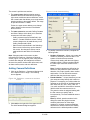
• MPCPU B: Read from the MPCPU B IP
address as defined in the System – Options
dialog box. This IP address is read-only in
Figure 41.
Retrieving Configuration Data
Do one of the following:
• For a new installation where no configuration data
file has been previously created, you should
initialize your system by retrieving (reading) into
EASY CPU the factory-default configuration data
residing in the CPU firmware. To do this, go to the
section, Factory-Default or Existing
Configuration Data in CPU, below.
• If you want to use an existing configuration file
that already has been written to the CPU, go to
the section, Factory-Default or Existing
Configuration Data in CPU, below.
• If you want to use an existing configuration file
that has not yet been written to the CPU, go to the
section, Configuration Data File Only in PC.
• If you want to create a new configuration file and
then write it to the CPU, go to the section, New
Configuration File, on page 20.
• User-specified IP: Enter an appropriate IP
address of your choosing. The default for this
field is defined in the Edit => Preferences
menu option.
4. In the MPCPU A, B, and Site No./Name as
specified in Sys => Options section, the Site No.
and Site Name fields only appear when either the
MPCPU A or MPCPU B radio buttons are
selected. They are for reference only and cannot
be changed in this dialog box. They are defined in
the System – Options dialog box.
5. Click the Read From Selected MPCPU button to
read the configuration from the selected MPCPU
IP address, or click Cancel to close the dialog
box without reading the configuration data.
6. Choose one of the following:
• If you want to enable user logins, go to the
section, Adding a User Login, on page 21.
Factory-Default or Existing Configuration
Data in CPU
Retrieve the factory-default or existing configuration
data from the CPU into EASY CPU by doing the
following:
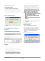
1. Click File on the main screen.
2. Click Read in the dropdown menu bar. The Read
from MPCPU dialog box appears.
• If you do not want to enable user logins, your
system is ready to use.
Configuration Data File Only in PC
After creating and saving a configuration data file in
EASY CPU, you must write (or transfer) the new
configuration settings to the CPU.
To write an existing configuration data file located in
your PC to the CPU, do the following:
Figure 41. Read from MPCPU dialog
1. Click File on the main screen.
2. Click Open… in the dropdown menu bar.
3. Locate and highlight the desired file in the Open
dialog box.
4. Click Open. The file is loaded into EASY CPU.
3. In the Select MPCPU IP to Read From section of
the dialog box, select one of the following radio
buttons:
Note: Only one MPCPU radio button at a time can
be selected for reading.
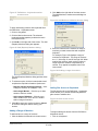
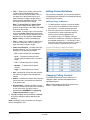
5. Click File on the main screen.
6. Click Write in the dropdown menu bar. The Write
to MPCPU and/or Save Configuration To File
dialog box appears (Figure 42).
• MPCPU A: Read from the MPCPU A IP
address as defined in the System – Options
dialog box. This IP address is read-only in
Figure 41. The default for this field is defined
in the Edit => Preferences menu option.
MEGAPOWER CPU
ADMINISTRATOR’S GUIDE
8200-0421-03, REV. G
18 of 82
path/filename by clicking the Browse button on
the right and navigating to the path/filename of
your choice in the dropdown list. When
unchecked, the configuration is not saved.
Figure 42. Write to MPCPU and/or Save
Configuration To File dialog
7. In the section labeled MPCPU A and/or B must be
specified in Sys => Options, choose one or both
of the following checkboxes depending on
whether you have a single MPCPU configuration
or both MPCPUs in a dual hotswitch configuration:
• MPCPU A: When checked, the configuration
is written to the indicated IP address, which is
defined in the System – Options dialog box.
This IP address is read-only in Figure 42.
When unchecked, the configuration is not
written to the indicated IP address.
• MPCPU B: When checked, the configuration
is written to the indicated IP address, which is
defined in the System – Options dialog box.
This IP address is read-only in Figure 42.
When unchecked, the configuration is not
written to the indicated IP address.
• Backup File: When checked, the configuration
is backed up to the path and filename shown in
the associated field. You can change the
path/filename by clicking the Browse button on
the right and navigating to the path/filename of
your choice in the dropdown list. When
unchecked, the configuration is not saved to
the backup file.
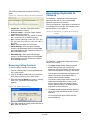
10. Click the Write Configuration To Selected
MPCPUs and/or Files button to begin writing the
configuration data into the CPU, or Cancel to
close the dialog box without writing the
configuration data.
When you click the Write Configuration To
Selected MPCPUs and/or Files button, each IP
address is checked to ensure it has a properly
formatted IP address. If either IP address has an
invalid IP address format, you will receive a
warning message. You will need to correct the
invalid format before continuing.
Figure 44. Invalid IP Address message box
Note: If both MPCPU IP addresses are the same,
a message box will appear stating that the
configuration will only be written once to the IP
address.
Note: If the configuration being written is a
version V1.00 configuration file, upon clicking
Write Configuration To Selected MPCPUs
and/or Files, you will be prompted whether or not
to convert the configuration to the V2.00 format
prior to writing to the MPCPUs.
Figure 43. MPCPU Addresses are the same
message box
Figure 45. Configuration File Conversion dialog
8. In the Site No./Name specified in Sys => Options
section, the Site No. and Site Name fields are for
reference only and cannot be changed in this
dialog box. They are defined in the System –
Options dialog box.
9. In the section labeled Config File Save and
Backup Options, choose one or both of the
following checkboxes:
• Save To File: When checked, the configuration
is saved to the path and filename shown in the
associated field. You can change the
MEGAPOWER CPU
ADMINISTRATOR’S GUIDE
8200-0421-03, REV. G
19 of 82
11. Choose one of the following:
defined in the System – Options dialog box.
This IP address is read-only in Figure 46.
When unchecked, the configuration is not
written to the indicated IP address.
• If you want to enable user logins, go to the
section, Adding a User Login, on page 21.
• If you do not want to enable user logins, your
system is ready to use.
• MPCPU B: When checked, the configuration
is written to the indicated IP address, which is
defined in the System – Options dialog box.
This IP address is read-only in Figure 46.
When unchecked, the configuration is not
written to the indicated IP address.
New Configuration File
Note: You must save a new configuration file to your
PC before EASY CPU allows you to write to the
MegaPower CPU.
Note: If both MPCPU IP addresses are the same,
a message box will appear stating that the
configuration will only be written once to the IP
address.
To create a new configuration file, do the following:
1. Click File on the main screen.
2. Click New in the dropdown menu bar.
3. Using the configuring information throughout this
guide, set up your system configuration.
Figure 47. MPCPU Addresses are the same
message box
4. When you have completed your configuration,
click File on the main screen.
5. Click Save or Save As… in the dropdown menu
bar.
6. Navigate through the Save or Save As… dialog
box to a desired folder, and enter an appropriate
file name for your configuration.
7. Click Save to save the file. The file is saved to
your PC.
8. Click File on the main screen.
9. Click Write in the dropdown menu bar. The Write
to MPCPU and/or Save Configuration To File
dialog box appears (Figure 46).
11. In the Site No./Name specified in Sys => Options
section, the Site No. and Site Name fields are for
reference only and cannot be changed in this
dialog box. They are defined in the System –
Options dialog box.
12. In the section labeled Config File Save and
Backup Options, choose one or both of the
following checkboxes:
• Save To File: When checked, the configuration
is saved to the path and filename shown in the
associated field. You can change the
path/filename by clicking the Browse button on
the right and navigating to the path/filename of
your choice in the dropdown list. When
unchecked, the configuration is not saved.
Figure 46. Write to MPCPU and/or Save
Configuration To File dialog
10. In the section labeled MPCPU A and/or B must be
specified in Sys => Options, choose one or both
of the following checkboxes depending on
whether you have a single MPCPU configuration
or both MPCPUs in a dual hotswitch
configuration:
• MPCPU A: When checked, the configuration
is written to the indicated IP address, which is
MEGAPOWER CPU
ADMINISTRATOR’S GUIDE
• Backup File: When checked, the configuration
is backed up to the path and filename shown in
the associated field. You can change the
path/filename by clicking the Browse button on
the right and navigating to the path/filename of
your choice in the dropdown list. When
unchecked, the configuration is not saved to
the backup file.
13. Click the Write Configuration To Selected
MPCPUs and/or Files button to begin writing the
configuration data into the CPU, or Cancel to
close the dialog box without writing the
configuration data.
8200-0421-03, REV. G
20 of 82
Note: When you click the Write Configuration
To Selected MPCPUs and/or Files button, each
IP address is checked to ensure it has a properly
formatted IP address. If either IP address has an
invalid IP address format, you will receive a
warning message. You will need to correct the
invalid format before continuing.
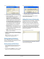
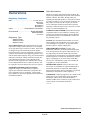
3. Click New User…. The Login Properties dialog
box appears (Figure 50).
Figure 50. Login Properties dialog
Figure 48. Invalid IP Address message box
14. Choose one of the following:
4. Complete the Login ID, Password, and Confirm
fields in the Login Properties dialog box for the
new user.
• If you want to enable user logins, go section
Adding a User Login below.
5. In the Access Level field, click on the scroll
buttons to choose the appropriate access level for
the new user (1 being the lowest level, 9 being the
highest level).
• If you do not want to enable user logins, your
system is ready to use.
Note: The Access Level field is grayed out for the
first user so that user will have all administrator
privileges. This field is available to set access
levels for subsequent users.
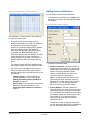
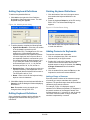
Adding a User Login
When you create a user login, the CPU login request
function is enabled. Users must log in to be able to
read and write configuration data.
CAUTION: Be sure that at least one user has an
access level of 9. Failure to maintain such a user
might lock users out of the system and require a
system reinstallation.
To create a user login:
1. With EASY CPU started and a configuration file
open, click Edit in the dropdown menu bar.
2. Click User Logins…. The EASY CPU – Login
Manager dialog box appears.
6. Click OK to save the new user properties or
Cancel to close the dialog box without saving the
properties.
Figure 49. Login Manager dialog
7. Repeat this process for all users for whom logins
are desired.
Note: You also can modify or delete users in the
Login Properties dialog box whenever buttons are
not grayed out.
8. Be sure to save these changes and write the
modified configuration file to the CPU.
Note: With the user login function enabled, all newly
initiated program sessions will require users to log in
before reading or writing configuration data.
MEGAPOWER CPU
ADMINISTRATOR’S GUIDE
8200-0421-03, REV. G
21 of 82
Logging in Users for CPU
Read/Write Access
When user logins are enabled, the Login dialog box
appears whenever you want to read a configuration
file from the CPU or write a configuration file to the
CPU.
Figure 51. Login dialog
1. In the Login dialog box, enter your user name and
password.
2. Click Logon to transfer configuration data or
Cancel to close the dialog box without transferring
configuration data.
MEGAPOWER CPU
ADMINISTRATOR’S GUIDE
8200-0421-03, REV. G
22 of 82
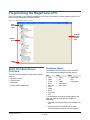
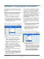
Programming the MegaPower CPU
EASY CPU allows you to program the MegaPower CPU from a connected PC. When started, the EASY CPU
main screen provides links to all setup features.
Figure 52. EASY CPU main screen
Dropdown
menu
Settings
window
display
area
Explore
menu
Status
bar
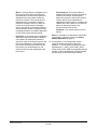
Dropdown Menus
EASY CPU Main Screen
Overview
The dropdown menus across the top of the EASY
CPU main screen provide the following options:
The EASY CPU Main Screen contains the following
sections:
• Dropdown menus
• Explore menu
• Status bar
• Setting window display area
File
Edit
Help
• New
• Copy*
• About EASY
CPU
• Open
• Cut
Configurator
• Close
• Paste*
• Save
• Preferences
• Save As
• User Logins
• Print
• Read
• Write
• Properties
• Exit
* To facilitate the configuring of large systems, the
copy and paste functions are also capable of
duplicating:
• Selected columns of a single row to multiple rows,
and
• Selected columns of multiple rows to areas
having the same number of rows and columns.
MEGAPOWER CPU
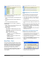
ADMINISTRATOR’S GUIDE
8200-0421-03, REV. G
23 of 82
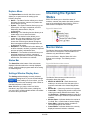
Explore Menu
Checking the System
Status
The Explore Menu on the left side of the screen
allows you to open screens for setting up the
following functions:
• Status – The Status function allows you to check
the status of monitors, cameras, the passive hot
switch and the error log.
• System – The System function allows you to set
options (site, user logon, snapshots, and CPU
addresses), date and time, and port
configurations.
• Switching – The Switching function allows you to
create salvos, tours, and event timers.
• Alarms – The Alarms function allows you to
create up to four alarm tables for use in event
timers. Through contact definitions, you can
choose the monitors where alarms will appear.
Alarm messages and Email messages also can
be displayed for review.
• Definitions – The Definitions function allows you
to define cameras, monitors, keyboards, keyboard
and user priorities, and satellite sites.
• Partitions – The Partitions function allows you to
associate cameras to monitors, cameras to
keyboards, keyboards to monitors, keyboards to
satellite sites, and monitors to cameras.
Status Bar
The Status Bar at the bottom of the main screen
displays information about the currently displayed
screen. It also provides progress status when saving
or transferring files.
EASY CPU allows you to check the status of
monitors, cameras, the passive hot switch, and the
error log by selecting the status function. Click on
Status links in the Explore menu to begin.
Figure 53. Status links
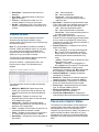
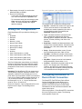
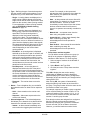
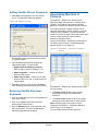
Monitor Status
The Monitor Status screen displays information about
each monitor in the system. The information is for
reference only and cannot be edited.
Click on the Status – Monitor Status link in the
Explore menu to begin. The following screen
appears.
Figure 54. Monitor status screen
Settings Window Display Area
The Settings window displays currently selected
screens and dialog boxes. If you see a small triangle
in the heading row for a column, you can
click on it to sort the rows according to the number or
character sequence in that column.
Note: Whenever you enter a value in a field or
checkbox in any EASY CPU screen or dialog box,
you must click in a field outside that field or checkbox
to set the value just entered.
MEGAPOWER CPU
ADMINISTRATOR’S GUIDE
The Monitor Status screen provides real-time
information about the system:
• MPCPU A / MPCPU B – Radio buttons that
enable you to select and view the status of the
monitors connected to the chosen MegaPower
CPU.
• Monitor No. – Lists every monitor in the system.
• Camera No. – Displays the pseudo number of the
video input currently called to the monitor. See
the Definitions – Cameras screen on page 43 to
reference video input numbers to pseudo camera
numbers.
• Monitor State – Indicates whether the monitor is
in a Hold, Run, or Salvo state of camera display.
• Alarm State – Indicates whether an alarm is
currently displayed on the monitor.
• Camera State – Indicates whether the currently
displayed camera is locked or unlocked.
8200-0421-03, REV. G
24 of 82
• Video State – Indicates the video loss level
detected.
• Sync State – Indicates whether a video sync
signal is detected.
• Tour No. – Indicates the number of a Tour
currently loaded or running on the monitor.
• Site No. – Indicates the site (1-30) called to the
monitor. The MegaPower CPU can control up to
30 sites.
•
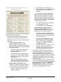
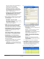
Camera Status
The Camera Status screen displays information
about the state and synchronization of each
camera’s video. The information is for reference only
and cannot be edited.
•
Note: The camera status information is loaded as
required. Initially the fields are empty. As you page
up or down, the screen will be populated from
requests made to the MegaPower CPU unit. This
allows you to only view what is needed.
Tool tips pop-up explanations appear whenever the
cursor hovers over a column heading.
Click on the Status – Camera Status link in the
Explore menu to begin. The following screen
appears.
•
Figure 55. Camera status screen
•
•
•
The Camera Status screen provides the following
information:
•
• MPCPU A / MPCPU B – Radio buttons that
enable you to select and view the status of the
cameras connected to the chosen MegaPower
CPU.
• Video Input – Displays the number of the
physical video input connector on the rear panel
of the MegaPower system.
• Camera No. – Displays the number that the
camera is referenced by on the keyboard and in
the EASY CPU configuration.
• Title 1 – Displays on the monitor the first line of a
camera title when the camera is called.
• Title 2 – Displays on the monitor the second line
of a camera title when the camera is called.
• Video State – Indicates the current video state of
the camera:
MEGAPOWER CPU
ADMINISTRATOR’S GUIDE
•
•
− Yes – Video is detected
− No – Video loss detected
− Don’t Care – Video loss detection not
configured, or no communication exists to
video loss card.
Sync State – Indicates the synchronization state
of the video signal to the selected camera and is
used in connection with the video loss setup:
− Yes – Video synchronization present
− No – Video synchronization not present
− Don’t Care – Video synchronization portion of
the video signal is ignored.
Note: The camera status screen columns for
Dome/PTZ On-line through Device Serial Number
are only used for the Dome/PTZ Device Direct
Connection to the MP CPU and not for AD2091 or
AD2083 connected domes.
Dome/PTZ On-Line – Indicates the on-/off-line
status of the dome:
− Yes – Dome/PTZ is currently answering polls
− No – Dome/PTZ has answered polls since
system power-on or reset, but is not currently
answering polls and has exceeded its retry
count
− – (dash) – Dome/PTZ has not answered a poll
since power-on or reset
− (blank) – Camera is not configured for a
direct MegaPower CPU dome/PTZ connection.
Dome/PTZ Connection– Displays codes
identifying the connection type: M for Manchester,
S for SensorNet, and R for RS-232/ RS-485.
Dome/PTZ Address – Displays the address
configured for the dome.
Mnemonic – Displays a six-character code that
identifies the dome type; for example, SDU 8.
Flash Version No. – Displays the 14-character
dome CPU board firmware version number.
Device Type – Identifies the dome CPU board
type; for example, 0150 for SDU 8.
Device Serial Number – Displays the
20-character dome serial number.
Device Date of Manufacture – Displays the
eight-character date the dome was manufactured.
Passive Hot Switch Status
The Passive Hot Switch Status screen displays the
real-time status of the passive hot switch between
dual MegaPower CPUs. This information is for
reference only and cannot be edited. The passive hot
switch monitors the status of the MPUs in a dual
MegaPower CPU system. If the selected MPU fails,
the passive hot switch switches to the non-selected
MPU.
8200-0421-03, REV. G
25 of 82
If only one MegaPower CPU IP address is specified,
the status of that MegaPower CPU is shown. If no
MPCPU A or B IP address is specified, the status of
the Edit => Preferences default IP address is shown
as MPCPU A.
•
•
Click on the Status – Passive Hot Switch Status link
in the Explore menu to begin. The following screen
appears (Figure 56).
•
Figure 56. Passive hot switch status screen
•
•
The Passive Hot Switch Status screen provides the
following information:
• MPCPU – Shows the names of the MegaPower
CPUs.
• Site # – Site number assigned to the MegaPower
CPUs. The site number is configured in the
System – Options dialog box. Range: 0-30.
• Site Name – Site name assigned to the
MegaPower CPU. The site name is configured in
the System – Options dialog box.
• DHCP Host Name – MegaPower CPU Host
name for DHCP IP communications.
• IP Address – Ethernet communications IP
address.
• MAC Address – MAC Address of the
MegaPower CPU Ethernet interface.
• Selected Status:
− Selected – indicates actively driving the AD
Data Lines and the RS-232 port transmitters.
− Backup – indicates standby MegaPower CPU
is in the dual hot switch system.
• Port Range:
− High 17–32 – MegaPower CPU rear slide
switch is up selecting com ports 17-32 &
ADDL 3-4.
MEGAPOWER CPU
ADMINISTRATOR’S GUIDE
•
− Low 1–16 – MegaPower CPU rear slide switch
is down selecting com ports 1-16 & ADDL 1-2.
Firmware Version – Displays the MegaPower
CPU firmware version number.
Last Selected:
− Yes – MegaPower CPU was switched to
Selected by pushing recessed button on unit.
− No – MegaPower CPU was not the last unit set
to Selected status.
Mating CPU Port Range:
− High 17–32 – MegaPower CPU rear slide
switch is up selecting com ports 17-32 &
ADDL 3-4.
− Low 1–16 – MegaPower CPU rear slide switch
is down selecting com ports 1-16 & ADDL 1-2.
Mating CPU Status:
− Good – Mating MegaPower CPU operational
with heartbeat.
− Bad – Mating MegaPower CPU has faults.
− None – MegaPower CPU ribbon cable
connected to itself.
− Open – MegaPower CPU ribbon cable not
connected.
− Off – Mating MegaPower CPU not
communicating.
Mating CPU IP Address – Ethernet
communications IP address of a paired unit in hot
switch configuration.
Alarm Relay:
− Normal – Relay center pin connected to NC
(normally closed) pin.
− Active – Relay center pin connected to NO
(normally open) pin.
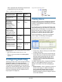
Error Log Status
You can view the status of the Error Log by selecting
on the Error Log Status screen. The information is for
reference only and cannot be edited.
Click on the Status – Error Log Status link in the
Explore menu to begin. The following screen
appears.
Figure 57. Error log status screen
8200-0421-03, REV. G
26 of 82
The Error Log Status screen provides the following
information:
Figure 59. System – options dialog
• MPCPU A / MPCPU B – Radio buttons that
enable you to select and view the error log for the
chosen MegaPower CPU.
• Fault – An abnormal condition detected by the
CPU. The system provides status on up to 12
faults.
• Count – Indicates the number of times the fault
has occurred.
• Error Code – Identifies the fault by number
(1,000–-9,999).
• Message – Provides a textual description of the
fault.
• Clear – Clears the error message from the error
log status screen and the CPU LCD screen. Click
to clear the error message.
The System – Options screen provides the following
options:
Configuring the System
• Site Number – Allows you to create a numeric
identifier for the local site (1–30).
The System function allows you to select sites,
enable logon, determine the system date, and
configure ports for keyboards, video loss detection,
and other devices.
• Site Name – Allows you to create a name for the
local site. Site names can be any length.
• Users Enable Logon – Checkbox implements
password protection on system resources, such
as cameras and monitors, through keyboards.
Click on the System links in the Explore menu to
begin.
Figure 58. System links
− Unchecked: The Definitions – Keyboard/User
Priorities screen appears where you can set
keyboard priorities.
− Checked: The Definitions – Keyboard/User
Priorities screen appears where you can
create individual passcodes.
• Snapshot – Section that enables you to take and
store snapshots of the currently selected monitor
after you have installed a TFTP server
application.
Setting System Options
The System Options function allows you to create
site numbers (1-30) and determine their date formats
and start dates. This function also allows you to
enable or disable the user logon.
Click on the System – Options link in the Explore
menu to begin. The following dialog box appears
(Figure 59).
MEGAPOWER CPU
ADMINISTRATOR’S GUIDE
− Installing a TFTP server:
A TFTP server application can be downloaded
from the Internet. After downloading the
application, install it on a PC in the same
Ethernet network as the CPUs according to
the instructions accompanying the application
or installation wizard. Then, configure the
application by specifying the TFTP root
directory where the Snapshot .jpg files will be
stored. Also, enter the range of permitted IP
addresses to match the IP addresses of the
CPUs in the system.
8200-0421-03, REV. G
27 of 82
− Viewing a Snapshot:
Note: The TFTP server application must be
running in the background of the server for
the snapshot feature to work.
To view a snapshot, open Windows Explorer
on the PC containing the TFTP server, locate
the TFTP root directory, and then double-click
on the filename of the image you want to
view.
− Taking a Snapshot:
To take a snapshot, first press 4, and then
press F1 on a keyboard. The system
automatically assigns a file name to the
snapshot and saves it in .JPG format to the
location defined in the TFTP server.
• Configuration – Allows you to specify the
maximum number of cameras, monitors, and
alarm contacts in your system, which limits the
overall size of the system database.
The file name is in the form:
− Max Cameras – Allows you to specify the
maximum number of cameras that can be used
in the system.
KBx–CAMz–cameratitle–yy-mm-dd(hhmmss),
where x is a number designating the
keyboard, and z is a number designating the
camera. The date can be alternately
configured as dd-mm-yy or mm-dd-yy. The
time is hhmmss, where hh is hours, mm is
minutes, and ss is seconds. If the cameratitle
is not configured, this part of the file name will
not be displayed.
You can choose the video standard, video
mode, image quality (in %) and server
parameters for the system.
− Max Monitors – Allows you to specify the
maximum number of monitors that can be used
in the system.
− Max Alarm Contacts – Allows you to specify
the maximum number of alarm contacts that
can be used in the system.
• CPU Addresses – Allows you to connect to the
local MegaPower CPUs. These CPU addresses
must be configured for EASY CPU to
communicate with the MegaPower CPU.
○ Video Standard – Choose either PAL or
NTSC.
○ Video Mode – Choose one of the
following: CIF, 2 CIF Progressive, QCIF,
HalfDI Progressive, HalfD1 Interlaced,
4CIF, Full D1, VGA, SIF, or 2SIF.
○ Image Quality – Choose from 1% to
100%.
○ Server 1 – Enter the IP address of the first
PC running a server where the snapshot
image will be saved.
○ Server 2 – Enter the IP address of the
second PC running a server where the
snapshot image will be saved. (Backup
server if first server is not available).
• CPU Language – Allows you to select the
language that will be displayed on the
MegaPower CPU LCD screen. The language
should correspond to the language defined for
EASY CPU.
Setting System Date and Time
The System Date & Time function allows you to
customize the system’s date and time or use the
PC’s current date and time. There are two ways to
set the system date and time:
• Using the System – Date & Time dialog box
○ Server 3 – Enter the IP address of the
third PC running a server where the
snapshot image will be saved. (Backup
server if first two servers are not available)
Note: Although the snapshot image is
simultaneously saved to all three servers, it
is only accessed from the currently
available server.
• Using a keyboard
Setting the Date and Time Using
the Dialog Box
Click on the System – Date & Time link in the
Explore menu to begin. The following dialog box
appears (Figure 60).
○ Monitor Output – Choose the monitor to
display the video to be captured in
snapshot mode. Choose from 1 to 256.
MEGAPOWER CPU
ADMINISTRATOR’S GUIDE
8200-0421-03, REV. G
28 of 82
− GMT Offset – This field is read-only and
displays the GMT offset selected in the GMT
Offset/Timezone/Region Settings field.
Figure 60. System – Date & Time dialog
• Daylight Saving Settings – Daylight Savings
Time (DST) values are written to the MegaPower
CPU, which uses them to determine when to
adjust for either DST or Standard Time. This
section contains the following choices:
– Enable DST Adjustments in MPCPU – Select
this checkbox to enable Daylight Savings Time.
If left unchecked, Standard Time is used, and
the button and all fields in this section are
disabled.
– Minutes To Adjust Forward on Start DST –
Use the scroll bar in this field to make fine
adjustments to the DST minutes.
– DST Start Date (Spring Forward) – Use the
dropdown calendar to choose the appropriate
DST start date, or highlight the portion of the
date or time to be changed and use the scroll
arrows that appear to make the change, or
manually enter the start date.
To set the system date and time, complete the
following sections:
• Set MPCPU’s Date/Time – This section contains
the following choices:
– Set MPCPU with current PC date/time –
Select this radio button if you want EASY CPU
to use the date and time from the PC where it is
installed.
– Set MPCPU using following date/time –
Select the radio button if you want to customize
the date and time. When selected, use the box
below this field to input a date and time.
– When you have chosen your selection, click the
Click to Set MPCPU’s Date/Time button to set
the MegaPower CPUs date and time.
• Select MPCPU’s Date Display Format – The
MPCPU Date Format field in this section enables
the date/time display on your video monitors and
is necessary when configuring system event
timers. Specify the date display format as
MM/DD/YY, DD/MM/YY, or YY/MM/DD.
• Network Time – Use this section to specify the
servers and mode of obtaining the date and time.
– DST End Date (Fall Back) – Use the
dropdown calendar to choose the appropriate
DST end date, or highlight the portion of the
date or time to be changed and use the scroll
arrows that appear to make the change, or
manually enter the end date.
• GMT Offset/Time Zone/Region Settings – This
field allows you to specify the global time zone
and region in which you are operating. When a
new time zone/region is chosen from the
dropdown list, the GMT offset is applied to the
network time and DST start and end dates.
Setting the Date and Time Using
the Keyboard
Do the following to use the keyboard to set system
date and time:
− Mode – The Mode field allows you to choose
whether the network time is Off or Polling. Poll
mode allows you to poll the network time server
for date and time.
1. Place the keyboard in Menu mode.
− Server 1 / 2 / 3 – Up to three network time
servers can be defined by entering their IP
addresses. If Server 1 is not available, then
Server 2 provides the date/time. If Server 2 is
not available, then Server 3 provides the
date/time.
3. Using the keyboard joystick (pan controls) or
left/right arrow keys, move to the date/time field
that you want to change. The > and < characters
will bracket the field you want to change.
MEGAPOWER CPU
ADMINISTRATOR’S GUIDE
2. Enter 102, and then press Enter on the keyboard.
The monitor will display lines for changing the
date and time.
4. Press Enter to set the field.
5. Using the joystick (tilt controls) or up/down arrow
keys, adjust the field to the desired value.
8200-0421-03, REV. G
29 of 82
6. Repeat steps 3 through 5 to set the other
date/time fields, as needed.
Figure 61. System – port configuration screen
7. Do one of the following:
− To save the new date/time settings and then
exit, return the keyboard to Operate mode.
− To exit without saving the new settings, press
Clear, and return the keyboard to Operate
mode. The monitor displays the original
date/time settings.
To configure ports, complete the following fields:
• Port No. – Identifies the number of the port on the
CPU to which the device is connected. Each
available port number expands by four when a
port expansion module is connected (see
Important explanation above).
Setting Port Configurations
Each MegaPower CPU provides the following port
types:
• Keyboard
• Recorder
• Satellite
• Alarms (1–1024)
• Alarms (1025–2048)
• Alarms (2049–3072)
• Alarms (3073–4096)
• Terminal
• Auxiliary
• Video Loss Detection (1–1024)
• Video Loss Detection (1025–2048)
• Video Loss Detection (2049–3072)
• Video Loss Detection (3073–3200)
• Type – Identifies the device connected to the
port. A predefined dropdown list offers the
following options: Keyboard, Recorder, Satellite,
Alarms, Terminal, Auxiliary, and Video Loss
Detection.
• Baud Rate – Identifies the data transmission rate
(in bps) of the connected device. Choose from the
following: 300, 1200, 2400, 4800, 9600, 19200,
and 38400.
• Parity – Detects transmission errors. Choose
from the following list: None, Odd, or Even.
• Data Bits – Identifies the number of bits in each
packet of data being transferred. Choose either 7
or 8.
• Stop Bits – Signals the end of each character
being transmitted. Choose either 1 or 2.
The Port Configuration setup allows you to identify
the device type (keyboard, port expansion module,
and others), baud rate, and other communications
parameters of each device connected to a port on
the CPU.
Important: The MegaPower CPU can support up to
128 keyboards using port expansion modules. Port
expansion modules convert a single port into four
ports. When a port expansion module is connected to
a port, port numbering adds an alpha character (a, b,
c, d) to each port number; for example, port one
becomes ports 1a, 1b, 1c, 1d; port two becomes
ports 2a, 2b, 2c, 2d, and so on.
Click on the System – Port Configurations link in the
Explore menu to begin. The following screen
appears.
• Location – Identifies the physical location of the
device. You can type up to 16 characters.
However, this field is for informational purposes
only, and any device location entered in this field
is not transferred to the MegaPower CPU.
Configuring the Dome/PTZ
Device Direct Connection
The Dome/PTZ (Pan/Tilt/Zoom) Device Direct
Connect Configuration screen allows you to
configure the MegaPower CPU to specify the
physical connections and protocol that enable
commands to be sent to domes connected to the
system video inputs.
Click on the System – Direct Dome/PTZ Connections
link in the Explore menu to begin. The following
screen appears (Figure 62).
MEGAPOWER CPU
ADMINISTRATOR’S GUIDE
8200-0421-03, REV. G
30 of 82
○ Setting values in the lower four port
group’s controls are unchanged from what
they were before this checkbox was
checked.
Figure 62. Dome/PTZ Device Direct Connect
Configuration screen
○ The red warning text is not displayed.
−
–
The Dome/PTZ Device Direct Connect Configuration
screen consists of five sections:
• The top section contains two checkboxes that
control how connections are generally set up.
Direct connection configured as below:
When checked, this checkbox causes the
MPCPU to issue commands out the Direct
Connect ports as configured in the lower four
port group’s control settings. Commands are
not sent through the ADDL.
○
The lower four port group’s controls are
now enabled for user input.
○
The red warning text is not displayed.
Both checkboxes unchecked from a
previously checked state (return to
defaults). If either checkbox is in a checked
state and the user unchecks that box:
○
A warning message box appears and
informs you that unchecking both boxes
will return the port group’s setting values
to the default values.
○
If you click OK, the settings for all the
controls will be returned to the default
values, and the screen will display as
described in the Neither checkbox
checked state above.
○
If you click Cancel, the checkbox you are
attempting to uncheck will remain
checked, and no changes to any of the
port group’s setting values will occur.
Note: Both checkboxes cannot be checked at the
same time.
−
Neither checkbox checked – This
unconfigured/default state causes the
MPCPU to send commands through both the
ADDL and the Direct Connect ports according
to the default settings.
o The lower four port group’s settings are
grayed out, and user input to these
controls is disabled.
o All values in the lower four port group’s
controls will be set to the default settings
(See Table 1 on page 32 for the default
settings values).
o A red warning text appears indicating
commands will be sent through both the
ADDL and the default direct connections.
−
Not using direct connections: When
checked, this checkbox causes the MPCPU
to send commands only through the ADDL.
• The bottom four sections (the Port Groups)
control the settings for the four MPCPU ports—
two SensorNet/Manchester ports and two
RS-422/–485 ports. These sections define how
video inputs are configured and what connections
and protocols the MPCPU should use to send
commands to the Dome/PTZ devices connected
to the video inputs.
All the port groups’ controls are enabled for user
input when the Direct connection configured as
below checkbox is checked. If the Not using
Direct Connection checkbox is checked or
neither checkbox is checked, the controls are
grayed out and disabled from user input.
○ The lower four port group’s controls are
grayed out, and the user input to the
controls is disabled.
MEGAPOWER CPU
ADMINISTRATOR’S GUIDE
8200-0421-03, REV. G
31 of 82
Table 1 describes the valid setting values that can
be specified for the four port groups:
Figure 63. Switching links
Table 1. Valid Port Group settings
Direct Connect
Settings Description
SensorNet/
Manchester
1/2
RS-422/
RS-485
1/2
Dome/PTZ Control:
Specifies the port
protocol
SensorNet
or
Manchester
RS-422/-485
or
RS-232
Patterns (SensorNet/
Manchester) or
Default Mode
(RS-422/-485):
Specifies whether to
use variable or legacy
speed patterns
Variable
or
Legacy
Variable
or
Legacy
Starting Video Input
Number: Physical
video connection
number that defines
start of group of inputs
controlled on this port
1 to 3200
1 to 3200
Starting Dome/PTZ
Address: The address
setting of the first
(lowest address)
Dome/PTZ connected
to video inputs on this
port
1 to 254
(SensorNet)
or
1 to 64
(Manchester)
1 to 100
No. of Dome/PTZ
Devices: The number
of Dome/PTZ devices
connected to this port.
0 to 254*
(SensorNet)
or
0 to 64*
(Manchester)
*See note.
0 to 100*
*See note.
A system Salvo is a group of cameras programmed
to display simultaneously on a contiguous group of
monitors. The MegaPower CPU allows you to create
up to 200 Salvos.
You can place up to 16 cameras in each Salvo, with
each camera having its own dwell time, Preset view,
auxiliary action, and link status. You can also insert a
Salvo as the last entry of a Salvo (in place of a
camera). This “nesting” of a Salvo within a Salvo
expands the number of different camera views.
Click on the Switching – Salvo link in the Explore
menu to begin. The following screen appears.
Figure 64. Salvos Camera tab screen
Note: The maximum value actually allowed for this setting
is the lesser of:
• The nominal maximum value: 254, 64, or 100
or
• Maximum video inputs (3200) minus Starting Video
Input No. + 1
Configuring Switching
Switching provides many of the automated functions
designed to enhance your video surveillance
practices. It allows you to create Salvos and set up
Tours that will run automatically. You can also use
switching to schedule different alarm monitor/contact
tables to become active at different times and days.
Click on the Switching links in the Explore menu to
begin (Figure 63 on page 32).
MEGAPOWER CPU
ADMINISTRATOR’S GUIDE
Creating Salvos
The Salvos screen is divided into two sections:
• The left side, “Salvos,” allows you to create Salvo
numbers and names.
• On the right side of the screen, the Cameras tab
section allows you to create the entries, cameras,
and other actions associated with each Salvo.
The Alarm Contacts tab section allows you to
specify the alarm contacts associated with the
highlighted Salvo.
To create a Switching Salvo, complete the following
fields. To create additional Salvos, click on the
asterisk in the header of the last row displaying a
Salvo.
• Salvos Number – Enter an identifying number for
a Salvo in the range of 1–9999. If you enter a
Salvo number that already exists, you will be
prompted to choose another Salvo number or
delete the existing one prior to using the value for
a new Salvo definition.
8200-0421-03, REV. G
32 of 82
You can change an existing Salvo number. If the
new Salvo number already exists, you will be
prompted to choose another number or delete the
existing one prior to using the new Salvo number.
(See the MegaPower CPU Operator’s Guide,
8200-0421-02, for more information on
Presets.)
− Aux – Identifies an auxiliary device to be
included as an action and determines the state
that the auxiliary will switch to when the Salvo
runs. To determine whether an auxiliary
operates when a Salvo runs, select one of the
following:
o Don’t Care – Ignores the auxiliary
o Aux 1-4 On – Activates auxiliaries 1, 2, 3, or
4 when the Salvo runs
o Aux 1-4 Off – Deactivates auxiliaries 1, 2,
3, or 4 when the Salvo runs
Any cameras and/or alarm contacts assigned to
the previous Salvo number will remain assigned
to the new Salvo number. Also, any references to
the previous Salvo number in the Alarms –
Contact Definitions screen will be changed to
reference the new Salvo number.
• Salvos Name – Enter a descriptive name for the
each Salvo. The name represents different
actions to be performed when the Salvo runs.
Define the characteristics of each entry by
completing the remaining fields on this screen.
− Link – Determines the next action associated
with the Salvo. Select one of the following.
o Yes – Causes the next camera entry in the
Salvo to be called to the next continuous
monitor
o No – Causes the Salvo to stop at the
camera position chosen above
o Salvo – Calls another Salvo to run and
stops the current Salvo
• Cameras Tab – The Cameras tab contains the
following fields:
− Position – An automatically assigned number
that identifies the location of the camera for the
Salvo.
− CameraNumber – Identifies by its pseudo
number the camera to be used in the salvo. If
the Link field is set to Salvo, the number in this
field refers to the Salvo number.
− Preset or Pattern – Identifies a Preset (0-96)
or a Pattern (0-3) associated with the camera to
be displayed. Enter the number of a Preset or
Pattern for the corresponding CameraNumber
field as follows:
Figure 65. Salvos Preset or Pattern Dropdown
List
• Alarm Contacts Tab – The Alarm Contacts tab
shows the contact definitions that are assigned to
the Salvo. This tab is read-only. You must use the
Alarms – Contact Definitions screen to assign a
contact definition to a Salvo.
Note: Only contact definitions with Link values of
“Salvo” and “Salvo Group Ack” will be assigned
the Salvo Number specified in the Alarms –
Contact Definitions screen “Camera or Salvo”
field.
The Alarm Contacts tab contains the following
fields:
Figure 66. Salvos Alarm Contacts tab screen
o For a Preset number, enter a numeric value
into the Preset or Pattern field. Ensure there
is no prefix displayed as part of the numeric
value entered. If the “Pat” prefix is
displayed, select “General Preset Number”
from the dropdown list to remove it.
o For a Pattern number, enter a numeric
value, and then select “Pattern Specific
Number” from the dropdown list. The
numeric value entered will now contain a
“Pat” prefix.
MEGAPOWER CPU
ADMINISTRATOR’S GUIDE
− Contact No. – Number of the alarm contact
associated with the salvo
− Preset or Pattern – Pattern or preset number
associated with the salvo
− Link – Choose either Salvo or Salvo Group Ack
− Aux – Choose either Don’t Care, Aux 1 On,
Aux 1 Off, Aux 2 On, Aux 2 Off, Aux 3 On, Aux
3 Off, Aux 4 On, or Aux 4 Off
− Dwell – Enter the time, in seconds, the salvo
will display on the set of monitors
8200-0421-03, REV. G
33 of 82
− Alarm Message – Enter the alarm message
number to be associated with the salvo. Note:
Alarm messages are first created in the Alarms
– Alarm Messages screen.
− Email Message – Enter the Email message
number to be associated with the salvo. Note:
Email messages are first created in the Alarms
– Email Messages screen.
Deleting Salvos or Alarm Contacts
• Tours can include Salvos, Presets, Patterns,
auxiliaries, and other Tours as entries.
• Any camera specified on one Tour entry can be
repeated on another entry using a different dwell
time, Preset, or auxiliary.
Click on the Switching – Tour link in the Explore
menu. The following screen appears.
Figure 68. Tours screen
To delete a Salvo or an alarm contact definition:
1. Click the header of the row that contains the Salvo
or alarm contact definition to be deleted.
2. Press the keyboard Delete key of the PC running
EASY CPU. The Delete Rows dialog box appears.
Figure 67. Delete Rows dialog
The Tours screen is divided into two sections. The
left side, “Tours,” allows you to create tour numbers
and names. The Cameras tab section on the right
side of the screen allows you to create the entries,
cameras, and other actions associated with each
Tour.
To create Tours, complete the following fields. To
create additional Tours, click on the asterisk in the
header of the last row displaying a Tour.
• Tours Section
3. Click Yes to delete the Salvo or alarm contact
definition or No to close the dialog box without
deleting the Salvo or definition.
− Numb – Assign a unique number to the Tour.
− Name – Create a name for the Tour using as
many characters as needed.
• Cameras Tab – Click the Camera tab and
complete the following fields:
Creating Tours
− Entry – Click on the row beneath Entry and
type a number to identify this entry. You will
define the characteristics of this entry by
completing the remaining fields across this row.
A system Tour is a programmed sequence of
different camera views switching one after another
on a monitor. Tours provide an efficient way for
operators to see multiple areas of interest without
having to call up cameras manually.
− Camera/Salvos/Tour – Enter the pseudo
number of a desired camera. If the Link field is
set to Salvo or Tour, the number in this field
respectively refers to the Salvo number or Tour
number.
You can call Tours to run on any monitor using
keyboard commands or schedule them to run
automatically by placing them within Event Timers
(see Event Timers on page 35).
You create System Tours by identifying each camera
action to run, the order in which each action will
appear on the monitor and the length of time the
action is to remain on the monitor before switching
(dwell time).
Key points to remember when programming Tours:
− Preset or Pattern – Indicates a Preset (0-96)
or a Pattern number (0-3) assigned to the
camera number selected above. Enter the
number of a Preset or Pattern for the
corresponding Camera/Salvos/Tour field as
follows (Figure 69):
• The system allows 64 system Tours, and every
Tour can include up to 64 Tour entries.
MEGAPOWER CPU
ADMINISTRATOR’S GUIDE
8200-0421-03, REV. G
34 of 82
Figure 69. Tours Preset or Pattern Dropdown List
Deleting Tours or Cameras
To delete a Tour or a camera definition:
1. Click the header of the row that contains the Tour
or camera definition to be deleted.
2. Press the keyboard Delete key of the PC running
EASY CPU. The Delete Rows dialog box
appears.
Figure 70. Delete Rows dialog
o For a Preset number, enter a numeric value
into the Preset or Pattern field. Ensure there
is no prefix displayed as part of the numeric
value entered. If the “Pat” prefix is
displayed, select “General Preset Number”
from the dropdown list to remove it.
o For a Pattern number, enter a numeric
value, and then select “Pattern Specific
Number” from the dropdown list. The
numeric value entered will now contain a
“Pat” prefix.
(See the MegaPower CPU Operator’s Guide,
8200-0421-02, for more information on
Presets.)
− Dwell – Indicates the number of seconds (0-61)
that any Tour entry is to be displayed on the
monitor.
− Aux – An auxiliary is a device (such as a light)
that can be activated when a Tour entry
activates. The MegaPower CPU recognizes up
to four auxiliaries per camera. To determine
whether an auxiliary operates when a Tour
runs, select one of the following:
o Don’t Care – Ignores the auxiliary
o Aux 1-4 On – Activates auxiliaries 1, 2, 3, or
4 when the Tour runs
o Aux 1-4 Off – Deactivates auxiliaries 1, 2,
3, or 4 when the Tour runs
− Link – The Link function links the Tour entry to
the next entry on the screen. Options are:
o Yes – Calls the next Tour entry to the next
contiguous monitor. By doing so, the user is
simulating a Salvo.
o No – Calls the next Tour entry to the
monitor originally called in the Tour
o Salvo – Calls the first entry of a preprogrammed Salvo to the monitor (each of
the Salvo’s remaining entries will appear on
contiguous monitors)
o Tour – Calls another pre-programmed Tour
to the monitor originally called
MEGAPOWER CPU
ADMINISTRATOR’S GUIDE
3. Click Yes to delete the Tour or camera definition
or No to close the dialog box without deleting the
Tour or definition.
Event Timers
Event Timers – Alarm Tables
Alarm Monitor/Contact Tables determine how the
system will respond to alarms and where the alarm
video will appear. The MegaPower CPU provides
one default Alarm Monitor/Contact table and allows
you to create four additional Alarm Monitor/Contact
tables associating different alarm contacts with
different monitors.
Using Event Timers, you can schedule any of the
four Alarm Monitor/Contact tables to become active
on different days and at different times.
For more information on Alarm Monitor/Contact
tables, refer to Creating Alarm Monitor/ Contact
Tables on page 40.
Click on the Alarm Tables tab in the Switching –
Event Timer link in the Explore menu to begin. The
following screen appears.
8200-0421-03, REV. G
35 of 82
Figure 71. Event timer–Alarm Tables tab screen
Figure 72. Event timer–Tours tab screen
Scheduling System Tours with the Event
Timer
To schedule system Tours using the event timer
feature, you will need the following information:
To schedule Alarm Monitor/Contact tables, you will
need the following information:
• The hour of the day/night you want the table to be
active
• The day(s) of the week you want the table to be
active
• The number of the system Tour you want to run
• The number of the monitor you want to display
the system Tour
• The day(s) of the week you want the Tour to run
• The hour of the day or night you want the Tour to
run
• The number of the desired alarm table
To create an Event Timer for alarms, complete the
following fields:
• Time – Select the hour and minute that you want
the alarm table to become active.
• Alarm Tables
– Day of Week – Displays the days of the week
– Alarm Table – Click on the field and select the
desired alarm table (0-4)
– State – Select one of the following:
To create a system Tour using the Event Timer, click
on the Tours tab and complete the following fields:
• MonitorNumber – Number of the monitor where
the tour is to be displayed
• Sunday through Saturday – Day of the week on
which the tour is to run
Deleting Tours in the Event Timer Screen
To delete a Tour in the event timer screen:
1. Click the header of the row in the left screen that
contains the time of the Tour to be deleted.
o Disabled – Event timer is disabled for the
day set in column 1
2. Click the header of the row in the right screen that
contains the Tour to be deleted.
o Enabled – Event timer is enabled for the
day set in column 1
o Not Used – Event timer is not used for the
day set in column 1
3. Press the keyboard Delete key of the PC running
EASY CPU. The Delete Rows dialog box
appears.
Figure 73. Delete Rows dialog
Event Timer – Tours
Event Timers enable the automatic call up of Tours
and alarm monitor/contact tables on specific days at
specific times. By scheduling these activities to occur
automatically, you can help ensure the surveillance
of key areas at important times. The MegaPower
CPU allows you to create 35 Event Timers.
Click on the Tours tab in the Switching – Event Timer
link in the Explore menu to begin. The following
screen appears.
MEGAPOWER CPU
ADMINISTRATOR’S GUIDE
4. Click Yes to delete the Tour or No to close the
dialog box without deleting the Tour.
8200-0421-03, REV. G
36 of 82
Figure 75. Alarms – Monitor screen
Configuring Alarms
The MegaPower CPU can respond to 4,096 alarms
by calling cameras, salvos, or Presets to armed
monitors and turning auxiliary devices on or off.
These alarm responses are defined in tables called
Alarm Monitor/Contact Tables.
EASY CPU provides one master Alarm
Monitor/Contact Table and four additional tables for
customizing monitor assignments. The master Alarm
Monitor/Contact Table conforms to the site
configuration of alarms and their associated cameras
and auxiliary devices. You should alter this table only
if the site configuration changes or in the event of
errors in previous data entries.
Each of the additional tables contains the same
associations of alarms to cameras, salvos, presets
and auxiliary devices as the master Alarm
Monitor/Contact Table. The difference between the
master table and any of the additional tables is in the
association of monitors to each alarm. You can
change the monitor associations in any of the
additional tables.
The system routes alarms to monitors depending on
which Alarm Monitor/Contact Table is active at the
time of the alarm. You can schedule Alarm
Monitor/Contact Tables to become active
automatically through Event Timers (see page 35).
Click on the Alarms links in the Explore menu to
begin (Figure 74 on page 37).
The Alarms–Monitor screen is split into an upper and
lower screen. The upper screen shows existing
monitor definitions and allows you to add new
definitions.
The lower screen provides two tabs that allow you to:
• Add contact arming to selected monitors.
• View or delete event timers associated with
selected monitors.
Adding Monitor Definitions
To create monitor definitions, click Add on the right
side of the Alarms-Monitor screen. The Add Monitors
dialog box appears.
Figure 76. Add Monitors dialog
Figure 74. Alarms links
Setting Up Alarm Monitors
The Alarms–Monitor screen allows you to arm
monitors to respond to alarms. You can arm each
monitor by setting up methods for displaying,
queuing, and clearing alarms.
To add monitors, complete the following fields:
Click on the Alarms–Monitor link in the Explore menu
to begin. The Monitors screen appears.
• Number of Monitors – Enter the number of the
monitor you want to define. The system will
number monitors consecutively starting with the
next highest available number.
If you plan to group several monitors together,
select a range of monitors.
MEGAPOWER CPU
ADMINISTRATOR’S GUIDE
8200-0421-03, REV. G
37 of 82
• Type – Defining the type of monitor determines
how the monitor treats incoming alarms. From a
dropdown list, you can define each monitor as:
normal. For example, a door opens and
activates the alarm: Closing the door clears the
alarm instantly. An operator can manually
override this alarm.
− Single – incoming alarms are displayed on a
single monitor. Multiple alarms received at a
single monitor will be either sequenced or held
based on the monitor’s alarm queuing method.
For an explanation of alarm queuing methods,
refer to APPENDIX H: Monitor Arming
Methods on page 74.
− Auto – an alarm resets at its source after a 20second delay. For example, a door opens and
activates an alarm. The door is closed
immediately, but the alarm will not clear unless
the door remains closed for a 20-second
interval. An operator can manually override this
alarm.
− Block – incoming alarms are displayed on a
block (group) of monitors with which they are
associated. The first incoming alarm is
displayed on the first (lowest numbered)
monitor of the block. The second alarm is
displayed on the next lowest numbered monitor
of the block, and so on. When all monitors in a
given block are displaying alarm video signals,
all subsequent alarms are either held in queue
or sequenced until the displayed alarms are
cleared depending on the monitor alarm
queuing method.
− Dual Hold – an incoming alarm is displayed
and held on the first of the pair of monitors until
cleared. All subsequent alarms are queued in
order on the second monitor until the current
held alarm is cleared from the first monitor. As
alarms are cleared off the first monitor, the
stacked alarms on the second monitor are then
transferred to the first monitor.
− Dual Sequence – an incoming alarm is
displayed and held on the first of the pair of
monitors until cleared. All subsequent alarms
are queued in order on the second monitor until
the current held alarm is cleared from the first
monitor. As alarms are cleared off the first
monitor, the sequenced alarms on the second
monitor are transferred to the first monitor.
− Disarmed – The monitor does not receive
alarms.
• Status – From a dropdown list, you can define
the selected monitor for either hold or sequence
status.
− Hold – Alarm remains on the monitor until
cleared
− Sequence – Alarms are sequenced on the
monitor until cleared
• Acknowledgement – The Acknowledgement
field allows you to determine how alarms will be
cleared for the selected monitor. Options are:
− Instant – an alarm resets immediately at its
source when the triggering device returns to
MEGAPOWER CPU
ADMINISTRATOR’S GUIDE
− Manual Ack. – an operator must clear the
alarm using a keyboard command.
− Instant No Ack. – Alarm resets instantly after
alarm condition goes away. No
acknowledgement from the operator is
permitted.
− Auto No Ack. – Alarm resets 20 seconds after
alarm condition goes away. No
acknowledgement from the operator is
permitted.
• Group these monitors together
You can define several monitors as a group (or
block) for the purpose of displaying multiple
cameras or Salvo alarms. To create a group:
1. Select a range of monitors in the Number of
Monitors field.
2. Select Block in the Type field.
3. Click the box next to “Group these monitors
together.”
Click OK to display the new monitor arming
configuration or Cancel to close the dialog box
without displaying the monitor arming configuration.
Remember to save and transfer your changes before
closing EASY CPU.
After clicking OK, the system will automatically
assign the same group number to each monitor in
the group. The group number will be the same as the
first monitor number in the group.
For example, suppose you create a group comprised
of five monitors starting at monitor number 12. The
system will assign monitor numbers 12, 13, 14, 15,
and 16 to the five monitors, but they will share the
number 12 as their group number.
Even though monitors are assigned in a contiguous
block, the armed monitors can be selectively
disarmed by changing the Type field to “Disarmed”
for each one that you do not want to be armed.
However, you cannot interleave monitor blocks.
8200-0421-03, REV. G
38 of 82
Contact Arming
Deleting Contacts
The Contact Arming screen enables you to assign a
group of contacts in an alarm table to a monitor.
To delete contacts assigned to a monitor as defined
in the Contact Arming tab, do the following:
Figure 77. Contact Arming screen
1. In the upper screen, click on the monitor that
contains the contact(s) to be deleted.
2. Click on the contact(s) in the lower screen to be
deleted, and then press Remove on the right side
of the screen.
To begin assigning a group of contacts to a monitor
from the Alarms – Monitor screen:
Event Timers
1. Click on a monitor.
The Event Timers tab in the Alarms – Monitor screen
allows you to view and delete event timer information
that is associated with selected monitors.
2. Click the Contact Arming tab. The selected
monitor number appears just below the tab in the
Monitor field.
3. Click Add on the right side of the screen. The Add
Contacts dialog box appears (Figure 78 on
page 39).
Note: Event timers displayed in this screen are for
information only, and they cannot be added or edited
here. You must define event timers in the Switching –
Event Timer screen as described on page 35.
Viewing Event Timers
Figure 78. Add Contacts dialog
To view event timer information from the Alarms –
Monitor screen:
1. Click on a monitor in the upper screen.
2. Click the Event Timers tab on the Alarms –
Monitor screen.
Figure 79. Event timers screen
Deleting Event Timers
To delete an event timer definition:
The Add Contacts dialog provides three options.
1. Click on a monitor in the upper screen.
1. To select an option, click the button beside the
option, and complete the required information.
Options are:
2. Click the header of the row in the lower screen
that contains the event timer definition to be
deleted.
− Replace with the following sequence – enter
a range of monitors, for example, 1-256.
− Add a single Contact – Click the up or down
arrows to select a contact.
3. Press the keyboard Delete key of the PC running
EASY CPU. The Delete Rows dialog box
appears.
− Add a range of Contacts – Click the up or
down arrows on the “from” and “to” fields to
select a range of contacts.
2. Click OK to save your contact choices or Cancel
to close the dialog box without saving your
choices.
MEGAPOWER CPU
ADMINISTRATOR’S GUIDE
8200-0421-03, REV. G
39 of 82
• Preset or Pattern – Indicates a Preset (0-96) or a
Pattern number (0-3) assigned to the camera
number or Salvo selected above. Enter the
number of a Preset or Pattern for the
corresponding camera number or Salvo field as
follows:
Figure 80. Delete Rows dialog
Figure 82. Contact Definitions Preset or Pattern
Dropdown List
4. Click Yes to delete the event timer definition or
No to close the dialog box without deleting the
definition.
Creating Alarm Monitor/
Contact Tables
Alarm Monitor/Contact Tables allow you to associate
alarm contacts with cameras or Salvos, Presets, and
auxiliaries. You can set the alarm dwell time,
auxiliary states, connections, and the locations of
each alarm contact.
− For a Preset number, enter a numeric value
into the Preset or Pattern field. Ensure there is
no prefix displayed as part of the numeric value
entered. If the “Pat” prefix is displayed, select
“General Preset Number” from the dropdown
list to remove it.
Click on Alarms – Contact Definitions to begin. The
following screen appears (Figure 81).
Figure 81. Alarms – contact definitions screen
− For a Pattern number, enter a numeric value,
and then select “Pattern Specific Number” from
the dropdown list. The numeric value entered
will now contain a “Pat” prefix.
(See the MegaPower CPU Operator’s Guide,
8200-0421-02, for more information on
Presets.)
• Link – Allows linking of a contact definition to
another contact definition, salvo, or wired set of
alarm contacts. Linked options are:
To create Alarm Monitor/Contact Tables, complete
the following fields:
• Contact No. – Determined by the following:
– No - Indicates that the alarm contact entry
either is not linked with another alarm contact
or is the last entry of a linked group of alarm
contacts.
MPCPU port designation Alarms (1-1024),
Alarms (1025-2048), Alarms (2049-3072), or
Alarms (3073-4096), and either:
− The physical contact point on the AD2096A
Alarm Interface Unit and the AD2096A DIPswitch settings, or
− The dome address and the AD2083-xx RS-422
Distributor’s DIP-switch setting for the Number
of Alarm Contacts per Dome
• Camera or Salvo – Specifies the camera pseudo
number or Salvo to be called when the alarm
activates. If the Link field is set to Salvo or Salvo
Group Ack, the number in this field refers to the
Salvo number.
MEGAPOWER CPU
ADMINISTRATOR’S GUIDE
– Yes - Indicates that the alarm contact entry will
be linked to the next alarm contact entry
programmed into the system. A group of
contacts linked in this way emulates a system
Salvo (more than one camera action runs in
response to an alarm).
– Salvo - Indicates that the alarm contact entry
will call a Salvo to a block of monitors.
− Wired - Indicates that the alarm contact entry
will be linked to the following entry in a wired
set. A wired set is a set of alarm contacts.
8200-0421-03, REV. G
40 of 82
When any member of the set is activated, all
members of the set are activated.
Figure 83. Email Message dialog
Each member of a wired set must be
designated as “Wired Set” or “Wired Group
Ack,” except the last member of the set, which
must be designed as “No,” “No Group Ack,”
“Salvo,” or “Salvo Group Ack.”
− No Group Ack, Yes Group Ack, Salvo Group
Ack, Wired Group Ack – When an alarm is
cleared manually by a keyboard operator, all
alarms in the wired set are cleared.
• Aux – Identifies an auxiliary device to be included
as an action when this alarm activates. Choose
from the following:
– Don’t Care – Ignores the auxiliary
– Aux 1-4 On – Activates auxiliaries 1, 2, 3, or 4
when an alarm is triggered
– Aux 1-4 Off – Deactivates auxiliaries 1, 2, 3, or
4 when an alarm is triggered
• Dwell – When the monitor is armed to sequence
alarms, the dwell time specifies how long an
alarm stays on screen before the next alarm in
queue takes its place. Options are 1-60 seconds.
1. To prepare an Email message, complete the
following fields in the dialog box:
– Host Address – Enter the IP address of the
host Email server.
• Alarm Message – Message that appears on a
given monitor when an alarm is activated. Alarm
messages are created in the Alarm – Alarm
Messages screen.
– Send To: – Section that allows up to three
Email addresses to be designated.
– Email Address – Enter each Email address
that you want the message to go to.
After the alarm message is created, enter the
alarm message number in the Alarm Messages
field of the Alarm – Contact Definitions screen.
– Subject – Enter a subject line that briefly
describes the action to take in the event an
alarm occurs.
• Email Message – Text of Email message
delivered to recipients designated in the Alarms –
Email messages screen (Figure 86). A message
can be sent to any designated Email address in
the event of an alarm.
To create an Email message, click on the Email
Message field and the following appears:
– Message – Add descriptive text that will
help the reader to understand what needs to
be accomplished.
2. Click OK to save and close the dialog box.
− <<Add New…>> – When you select this, click
again outside this field and the following dialog
box appears (Figure 83).
• Alarm Trigger – Enables the configuring of dome
input alarms. The first two columns, Dome and
Dome Input can be edited while the third column,
Video Loss Camera (range) is read-only.
Figure 84. Alarm Trigger Columns
MEGAPOWER CPU
ADMINISTRATOR’S GUIDE
8200-0421-03, REV. G
41 of 82
• Address 1 – Enter the Email address of the 1st
person that you want the message to go to.
– Dome – Enter a Camera Number (pseudo
number) of a dome configured for input
alarming (1-9999).
– Dome Input – Enter a value in the range of
1-4. This entry is the dome input alarm contact
number.
– Video Loss Camera (range) – This column is
read-only and displays any camera ranges that
have a video loss contact set. These contact
sets are configured in the Definitions –
Cameras screen.
• Address 2 – Enter the Email address of the 2nd
person that you want the message to go to.
• Address 3 – Enter the Email address of the 3rd
person that you want the message to go to.
• Subject – Enter the subject text that you want to
appears in the subject header of the Email
message. The subject can contain a maximum of
16 characters.
• Body – Enter the text of the Email message.
Alarm Messages
The Alarms – Alarm Messages screen allows you to
enter the text for an alarm message and assign a
number to this alarm message. The alarm message
can be up to 16 characters in length. The number
assigned to the message can then be entered in the
Alarm Messages field of the Alarms – Contact
Definitions screen.
This message text appears on a monitor when the
monitor is in an alarm state.
Defining System
Devices
The definitions section of EASY CPU allows you to
identify, define, and set up cameras, keyboards,
satellite sites, and recording devices. Click on the
Definition links in the Explore menu to begin.
Figure 87. Definitions links
Figure 85. Alarms – alarm messages screen
Email Messages
Defining Cameras
The Alarms – Email Messages screen (Figure 86)
allows you to create an Email message that can be
sent to up to three Email addresses in the event of
an alarm.
The Definitions – Cameras screen allows you to
create pseudo camera numbers, camera titles, and
title positions on the monitor display. You can also
identify the remote site that provides the video trunk
to the selected local camera input, the remote
monitor output, the type of camera, and its location.
Figure 86. Alarms – Email messages screen
Additionally, when you define cameras, you can also
set up alarm contacts and Salvo call-ups.
Complete the following fields:
• From Address – Enter the Email address of the
account sending the Email.
• Number – Enter an identification number for the
Email message.
Tool tips pop-up explanations appear whenever the
cursor hovers over a column heading.
Click on the Definitions – Cameras link in the Explore
menu to begin. The following screen appears.
• Host Name – Enter the IP address of the host
Email server.
MEGAPOWER CPU
ADMINISTRATOR’S GUIDE
8200-0421-03, REV. G
42 of 82
Figure 88. Definitions – Cameras screen
Adding Camera Definitions
You can create and edit camera definitions.
1. To add new camera definitions, click Add on the
right side of the screen. The Add Cameras dialog
box appears.
Figure 89. Add Cameras dialog
The Definitions – Cameras screen can be split into
an upper and lower screen.
• The upper screen shows existing camera
definitions and allows you to add new definitions.
All of the fields can be edited except the
Dome/PTZ Connection and Dome/PTZ Address,
which are read-only fields. The Dome/PTZ
Connection field displays codes identifying the
connection type: M for Manchester, S for
SensorNet, and R for RS-232/ RS-485. This field
is also highlighted in red if the connection is
configured to go out the ADDL. The Dome/PTZ
Address shows the address configured for the
dome.
The Calling Contacts and Salvo Contacts fields
only display a range value until selected for edit.
2. Complete the following fields:
• The lower screen only appears when either the
Calling Contacts field or Salvo Callups field is
selected, and provides a tab that allows you to do
the following:
− Calling Contacts – View and edit alarm
contacts associated to call a camera. See
Adding and Deleting Calling Contacts to
Cameras on page 44.
− Salvo Callups – View and edit Salvo call-ups
associated with selected cameras. See
Associating Salvo Callups to Cameras on
page 45.
• Number of Cameras – Enter the number of
cameras you want to define. The system will
number these cameras consecutively starting
with the next highest available number.
Camera numbers identify the video input
connection number on the switcher.
Note: If multiple cameras are defined at the
same time, they share the same video loss
detection, site, output, pan/tilt, alarm number,
and location. You can edit each camera’s
definition after they have been created.
• Pseudo Number – Pseudo numbers are
unique identifiers you can give cameras to help
identify their location or purpose. For example,
you could number the cameras on the first floor
of a building starting with 1000, such as: 1001,
1002, 1003, etc. You could use 2000 for
second floor cameras, 3000 for third floor
cameras and so on.
The pseudo number is assigned starting with
the first camera you specify and is incremented
by 1 for each additional camera specified.
MEGAPOWER CPU
ADMINISTRATOR’S GUIDE
8200-0421-03, REV. G
43 of 82
Note: By default, pseudo numbers in this
dialog box match the physical camera
numbers. In all other screens and dialogs,
references to camera numbers are actually
references to the defined pseudo numbers.
Editing Camera Definitions
Once a camera is defined, you can edit the definition
by highlighting the information in the desired field and
entering new information.
• Title 1 – You can create a two-line title for
each camera that will display on the monitor
when the camera is called. Title 1 is the upper
line of the title and can be up to eight
characters or digits in length with the pseudo
number appended to the title. Titles over eight
characters are truncated.
• Title 2 – Title 2 allows you to create the lower
line of a two-line camera title. Title 2 can be up
to eight characters or digits in length.
• Video Loss Detection – Provides video loss
detection alarming. You can set video loss
detection for the following conditions:
For example, to position Title1 on the monitor, click
on the Center Title1 field, and choose the desired
title position from the dropdown menu that appears:
Left, Center, Right, or None (no title will be
displayed).
Adding and Deleting Calling
Contacts to Cameras
The Calling Contacts tab allows you to specify the
alarm contacts associated with the highlighted
camera.
To view and edit this tab, double-click on the Calling
Contacts field in the highlighted camera row.
− Off – Video loss detection not enabled
− Sync – To detect the presence or loss of
the synchronized portion of the video signal
Figure 90. Cameras Calling Contacts tab screen
− Low – To detect low picture content
− Medium – To detect medium picture
content
− High – To detect high picture content
The Calling Contacts tab contains the following
fields:
Note: For detailed information on configuring
for video loss detection, go to APPENDIX F:
Configuring Video Loss Detection on
page 71.
• Contact No. – Number of the alarm contact
associated with the camera
• Preset or Pattern – Pattern or preset number
associated with the camera
• Site – Identifies the remote site that provides
the video trunk inputs to the selected local
camera.
• Link – Choose either No, Yes, Wired, No Group
Ack, Yes Group Ack, or Wired Group Ack
• Output – Identifies the monitor output from the
remote site that is connected to the selected
local camera input.
• Aux – Choose either Don’t Care, Aux 1 On,
Aux 2 On, Aux 3 On, Aux 4 On, Aux 1 Off,
Aux 2 Off, Aux 3 Off, or Aux 4 Off
• Alarm Number – Specifies an alarm contact
number to activate when video loss is detected
on this video input. See alarm contact
definitions and APPENDIX F: Configuring
Video Loss Detection on page 71.
• Dwell – Enter the dwell time in seconds
3. Click OK to display the new definition or Cancel
to close the dialog box without displaying the
definition.
Note: Remember to save or transfer your
changes before closing EASY CPU.
• Alarm Message – Enter the alarm message
number to be associated with the camera.
Note: Alarm messages are first created in the
Alarms – Alarm Messages screen.
• Email Message – Enter the Email message
number to be associated with the camera.
Note: Email messages are first created in the
Alarms – Email Messages screen.
To close the Calling Contacts tab, click the Close
Grid button
MEGAPOWER CPU
ADMINISTRATOR’S GUIDE
on the right side of the screen.
8200-0421-03, REV. G
44 of 82
assigned in Column 3 (Preset or Pattern) of the
Switching – Salvo– Cameras tab screen.
Deleting Calling Contacts
To delete calling contacts:
1. Click on a camera in the upper screen.
2. Click the header of the row in the lower screen
that contains the calling contact to be deleted.
3. Press the keyboard Delete key of the PC running
EASY CPU. The Delete Rows dialog box
appears.
Figure 91. Delete Rows dialog
• Aux – Displays the On, Off, or Don’t Care state of
devices designated as Aux 1, Aux 2, or Aux 3
when that camera is called by this salvo. This
parameter is assigned in Column 4 (Aux) of the
Switching – Salvo – Cameras tab screen.
• Link – Displays the link state. Options are:
– No – The salvo will not execute any parameters
beyond those defined in that row.
– Yes – The salvo will link to and execute the
next line.
– Salvo – The salvo will link to and execute the
next salvo.
To close the Salvo Callups tab, click the Close Grid
button
on the right side of the screen.
Deleting Salvo Callups
4. Click Yes to delete the calling contact or No to
close the dialog box without deleting the calling
contact.
To delete salvo callups:
1. Click on a camera in the upper screen.
2. Click the header of the row in the lower screen
that contains the salvo callup to be deleted.
Associating Salvo Callups to
Cameras
3. Press the keyboard Delete key of the PC running
EASY CPU. The Delete Rows dialog box
appears.
The Salvo Callups tab allows you to specify the
Salvos associated with the highlighted camera.
To view and edit Salvo callups from the Definitions –
Cameras screen, double-click on the Salvo Callups
field in the highlighted camera row.
Figure 93. Delete Rows dialog
Figure 92. Salvo callups screen
4. Click Yes to delete the salvo callup or No to close
the dialog box without deleting the salvo callup.
The Salvo Callups tab displays the following
information:
• SalvoNumber – Displays the Salvos associated
with selected cameras.
• Position – Number associated with a salvo, as
defined in Column 1 (Position) of the Switching –
Salvo – Cameras tab screen.
• Preset or Pattern – Displays the number
assigned to the preset coordinates or pattern
moves that the camera will execute when that
camera is called by this salvo. This number is
MEGAPOWER CPU
ADMINISTRATOR’S GUIDE
8200-0421-03, REV. G
45 of 82
− System Port Number – Enter the port number
of the keyboard’s connection to the MegaPower
CPU. The MegaPower CPU can support up to
128 keyboards using port expansion modules.
Port expansion modules convert a single port
into four ports. When a port expansion module
is connected to a port, port numbering adds an
alpha character (a, b, c, d) to each port
number; for example, port one becomes ports
1a, 1b, 1c, 1d; port two becomes ports 2a, 2b,
2c, 2d, and so on.
Defining Keyboards
The Definitions – Keyboards screen allows you to
identify keyboards and the ports that connect them.
Click on the Definitions – Keyboards link in the
Explore menu to begin. The Keyboards screen
appears.
Figure 94. Definitions – Keyboards screen
− Expansion Port – Choose the port on the
expansion port module (if the MegaPower CPU
is so equipped) that the keyboard will connect
to. The choices are a, b, c, or d.
− Name – Enter a name for the keyboard using
alpha or numeric characters.
3. Click OK to display the new definition or Cancel
to close the dialog box without displaying the
definition.
Note: Remember to save or transfer your
changes before closing EASY CPU.
The Definitions – Keyboards screen is split into an
upper and lower screen
Editing and Deleting Keyboard Definitions
Once a keyboard is defined, you can edit the
definition by highlighting the information in the
desired field and typing in new information.
• The upper screen shows existing keyboard
definitions and allows you to create new
definitions.
• The lower screen provides two tabs that allow
you to set up monitor access and site access for
each keyboard.
To delete a keyboard definition:
1. Click on the leftmost blue portion of the row in the
upper screen containing the keyboard definition.
The entire row turns blue.
2. Press Delete on the PC keyboard. The Delete
Row dialog box appears.
Adding Keyboard Definitions
You can create, edit, and delete keyboard definitions.
1. To add new keyboard definitions, click Add on the
right side of the screen. The Add Keyboard dialog
box appears (Figure 95 on page 46).
Figure 96. Delete Row dialog
Figure 95. Add Keyboard dialog
3. Click Yes to delete the keyboard definition or No
to retain the keyboard definition.
Adding Monitor Access to Keyboards
2. To add keyboards, complete the following fields:
MEGAPOWER CPU
ADMINISTRATOR’S GUIDE
The Monitor Access tab on the Definitions –
Keyboards screen allows you to enable selected
keyboards to access monitors.
8200-0421-03, REV. G
46 of 82
2. Click Add on the right side of the lower screen.
The Add Monitors to monitor access dialog box
appears.
Figure 97. Definitions – keyboards monitor
access screen
Figure 99. Add Monitors to Monitor Access dialog
To begin associating monitors with keyboards from
the Definitions – Keyboards screen:
1. Click on a keyboard.
2. Click the Monitor Access tab. The selected
keyboard number appears just below the tab in
the keyboard field.
3. Click Add on the right side of the screen. The Add
(Replace) Monitors dialog box appears.
Figure 98. Add (Replace) Monitors dialog
3. Enter the numbers of the monitors or range of
monitors you want to associate with a specific
keyboard.
For example, Figure 100 displays a range of
monitors for Keyboard 1. The range of monitors
are 1, 5, 8 through 10, and 55 through 128. When
entering the monitors, each monitor number or
range of monitor numbers is separated by a
comma. They appear as separate rows in the
lower screen.
Figure 100. Adding a range of monitors
The Add (Replace) Monitors dialog provides three
options.
4. To select an option, click the button beside it and
complete the required information. Options are:
− Replace with the following sequence – enter
a range of monitors, for example, 1-256.
Adding Site Access to Keyboards
− Add a single Monitor – Click the up or down
arrows to select a monitor.
The Site Access tab on the Definitions – Keyboards
screen allows you to enable selected keyboards to
gain access to satellite sites.
− Add a range of Monitors – Click the up or
down arrows on the “from” and “to” fields to
select a range of monitors.
Figure 101. Site access screen
5. Click OK to save your monitor choices or Cancel
to close the dialog box without saving your
choices.
Adding a Range of Monitors
To add monitors or a range of monitors:
To begin enabling site access from the Definitions –
Keyboards screen:
1. Click the Monitor Access tab in the lower screen.
1. Click on a keyboard.
MEGAPOWER CPU
ADMINISTRATOR’S GUIDE
8200-0421-03, REV. G
47 of 82
2. Click the Site Access tab. The selected keyboard
number appears just below the tab in the
keyboard field.
3. Click Add on the right side of the screen. The Add
Sites dialog box appears.
Figure 102. Add Sites dialog
Configuring Keyboard/User
Keyboards and Priorities
The Definitions – Keyboard/User Priorities screen
allows the administrator to assign priority access
levels to individual keyboards.
Priority levels determine whether the keyboard can
perform special functions, such as camera lock,
override, system reset, and others. You create
priority levels within the Priority Settings tab on the
Keyboard/Users Priorities screen.
Defining the Keyboard/User
Keyboards Configuration
To define the Keyboard/User Priorities – Keyboards
configuration, do the following:
1. Click on Keyboard/User Priorities link in the
Explore menu to begin.
The Add Sites dialog provides three options. To
select an option:
Important: Depending of the setting of the User
Enable Logon checkbox in the System – Options
dialog box, one of two screens will appear.
1. Click the button beside it and complete the
required information. Options are:
User Enable Logon checkbox settings:
− Replace with the following sequence – Enter
a range of satellite sites; for example: 1-30.
− Unchecked – Figure 103 appears and permits
assigning of keyboard priorities.
− Add a single Site – Click the up or down
arrows to select a satellite site.
− Add a range of Sites – Click the up or down
arrows on the “from” and “to” fields to select a
range of satellite sites.
− Checked – Figure 104 appears and permits
assigning of user priorities and passcodes.
Figure 103. Definitions – keyboard/user priorities
keyboard setup screen
2. Click OK to save your site choices or Cancel to
close the dialog box without saving your choices.
Removing Monitor or Site Access
To remove monitor or site access, do the following:
1. In the upper screen, click on the keyboard that
contains the monitor to be deleted.
2. In the lower screen, click on the monitor or site
access to be deleted, and then press Remove on
the right side of the screen.
2. In the Keyboards tab, complete the following
fields:
− Keyboard No. – Identifies the keyboard by its
physical connection to the CPU.
− Priority – Identifies the priority level (1-8)
assigned to the selected keyboard.
MEGAPOWER CPU
ADMINISTRATOR’S GUIDE
8200-0421-03, REV. G
48 of 82
Figure 104. Definitions – keyboard/user priorities
users setup screen
2. In the Priorities Settings tab, complete the
following fields:
− Priority No. – Identifies a level (1-8) to this
priority (1 = lowest priority, 8 = highest priority).
− Reset System – If enabled, the selected
priority level can clear all programmed
information from the CPU and return to factory
defaults.
− Lock Camera – If enabled, the selected priority
level can lock the control of a camera (equal or
lower priority levels will have view-only
capability).
3. In the Users tab, complete the following fields:
− Override – If enabled, the selected priority
level can override the keyboard/camera view
and control partitioning restrictions.
− User No. – Numeric reference assigned by the
administrator that identifies individual users.
− Priority – Identifies the priority level (1-8)
assigned to the user.
− Menu Access – If enabled, the selected priority
level can access menu programming.
− Passcode – Displays the passcode for access
to system resources, such as cameras and
monitors.
− Change Parameters – If enabled, the selected
priority level can edit system parameters
through menu programming (must have menu
access).
Configuring the Keyboard/User
Priority Settings
− Add User – If enabled, the selected priority
level can add new users.
The Keyboard/User Priorities setup allows you to
create up to eight priority levels that can be assigned
to keyboards and users. Each priority level grants a
different level of permission for control of cameras or
the system.
To configure the Keyboard/User priority settings, do
the following within the Priority Settings tab:
1. Click on Keyboard/User Priorities link in the
Explore menu to begin. The following screen
appears.
Deleting Keyboard/User Priorities Settings
To delete a keyboard, user, or priority settings:
1. Click on the appropriate tab.
2. Click on the leftmost blue portion of the row
containing the desired definition. The entire row
turns blue.
3. Press Delete on the PC keyboard. The Delete
Row dialog box appears.
Figure 105. Definitions – keyboard/user priorities
settings screen
Figure 106. Delete Row dialog
4. Click Yes to delete the definition or No to retain
the definition.
MEGAPOWER CPU
ADMINISTRATOR’S GUIDE
8200-0421-03, REV. G
49 of 82
Defining Satellite Sites
Controlling Access with
Partitions
The Satellite Sites setup allows you to identify
satellite sites and their port connections on the
MegaPower CPU.
Partitions control user access to cameras, monitors,
keyboards, and satellite sites. You can partition
cameras to monitors, keyboards to cameras,
keyboards to monitors, keyboards to satellite sites,
and monitors to cameras (Figure 109). The default
setting is “no partitions.”
1. Click on the Definitions – Satellite Sites link to
begin. The following screen appears.
Figure 107. Satellite sites screen
Partitioning provides the following capabilities:
• Camera to Monitor Access – Limits displaying
selected camera video on specified monitors.
• Keyboard to Camera Control Access – Limits
selected keyboards from controlling functions on
selected cameras; for example, pan/tilt/zoom, and
auxiliaries.
2. To define satellite sites, complete the following
fields:
− Site – Enter the unique site number (1-30) of
the satellite system. The unique site number
was created at the satellite site during setup.
• Keyboard to Camera View Access – Limits
selected keyboards from calling up selected
cameras for viewing and from directly accessing
video trunk inputs in a satellite network.
− Host Port – Enter the port to which the satellite
is connected on the local MegaPower CPU.
The same port must be selected on the System
– Port Configuration screen.
• Keyboard to Monitor Access – Limits selected
keyboards from accessing selected monitors and
from accessing video trunk outputs in a satellite
network.
− Remote Port – Enter the communication port
on the satellite system.
• Keyboard to Satellite Site Access – Limits
selected local keyboards from accessing all
cameras at selected satellite sites.
Deleting Satellite Sites
• Monitor to Camera Access– Limits selected
monitors displaying video from specified camera
inputs.
To delete satellite sites:
1. Click on the leftmost blue portion of the row
containing the desired satellite site: The entire
row turns blue.
Figure 109. Partitions link
2. Press Delete on the PC keyboard. The Delete
Row dialog box appears.
Figure 108. Delete Row dialog
3. Click Yes to delete the satellite site or No to retain
the satellite site.
MEGAPOWER CPU
ADMINISTRATOR’S GUIDE
Associating Cameras to
Monitors
The Partitions – Cameras to Monitors screen
determines which cameras can be called to which
monitors.
8200-0421-03, REV. G
50 of 82
The screen is split into two sections:
Figure 111. Add Cameras dialog
• The upper screen displays existing camera
definitions and has an Add button in the upper
right corner to add new camera definitions. It also
has a reset button that allows you to reset camera
pseudo numbers to the system default. The range
for pseudo numbers is 1-9999.
Further, the upper screen allows you to change
(add or delete) monitor access in the Monitor
Access column.
• The lower screen has two tabs: Calling Contacts
and Salvo Callups, which allow you to set alarm
contacts and view salvo callups.
− Calling contacts must first be defined in the
Alarms – Contact Definitions screen. Calling
contact changes can be made directly in the
Calling Contacts tab’s fields.
− Salvos must first be defined in the Switching –
Salvos screen before they can be viewed in
this screen. No changes to Salvos can be
made within this tab and is for information
only.
3. To partition cameras to monitors, complete the
following fields:
Note: Changes made in this screen are also
reflected in the Partitions – Monitors to Cameras
screen (Figure 131 on page 59). Also, when pseudo
numbers are changed, the changes are reflected
wherever the pseudo numbers are referenced, such
as alarm contact, salvo, and tour definitions.
Adding Camera Definitions
1. Click on the Partitions – Cameras to Monitors link
in the Explore menu to begin. The following
screen appears.
• Number of Cameras – Allows you to enter the
number of cameras you want to define. The
system will number these cameras
consecutively starting with the next highest
available number. Camera numbers identify
the video input connection number on the
switcher.
Note: If multiple cameras are defined at the
same time, they share the same video loss
detection, site, output, pan/tilt, alarm number
and location. You can edit each camera’s
definition after they have been created.
• Pseudo Number. – Unique identifiers you can
give cameras to help identify their location or
purpose. For example, you could number the
cameras on the first floor of a building starting
with 1000, such as: 1001, 1002, 1003, etc.
You could use 2000 for second floor cameras,
3000 for third floor cameras and so on.
Figure 110. Partitions – cameras to monitors
screen
The pseudo number is assigned starting with
the first camera you specify and is
incremented by 1 for each additional camera
specified.
Note: By default, pseudo numbers in this
dialog box match the physical camera
numbers (also known as Video Input
numbers). In all other screens and dialogs,
references to camera numbers are actually
references to the defined pseudo numbers.
2. Click Add on the right side of the upper screen.
The Add Cameras dialog box appears.
MEGAPOWER CPU
ADMINISTRATOR’S GUIDE
8200-0421-03, REV. G
51 of 82
• Title 1 – Allows you to create a two-line title
for each camera that will display on the
monitor when the camera is called. Title 1 is
the upper line of the title and can be up to
eight characters or digits in length with the
pseudo number appended to the title. Titles
over eight characters are truncated.
Note: The CenterTitle1 and Center Title2
columns in the upper screen allow you to
position the text shown in the Title1 and Title2
columns on the monitor.
For example, to position Title1 on the monitor,
click on the Center Title1 field of the desired
camera, and choose the title position from the
dropdown menu that appears: Left, Center,
Right, or None (no title will be displayed).
Editing Camera Definitions
Once a camera is defined, you can edit the definition
by highlighting the information in the desired field and
entering new information.
Adding a Range of Monitors
1. To add monitors or a range of monitors, doubleclick on a field in the Monitor Access column of
the Partitions – Cameras to Monitors screen.
2. Enter the numbers of the monitors or range of
monitors that you want to associate with the
camera of the currently highlighted row.
For example, Figure 112 displays a range of
monitors for five different cameras. For Camera 1,
the mapped monitors are 1, 5, 8 through10, and
55 through 128. Each monitor number or range of
monitor numbers is separated by a comma.
• Title 2 – Allows you to create the lower line of
a two-line camera title. Title 2 can be up to
eight characters or digits in length.
• Video Loss Detection – Provides video loss
detection alarming. You can set video loss
detection for the following conditions:
Figure 112. Adding a range of monitors
− Off – Video loss detection not enabled
− Sync – To detect the presence of the
vertical synchronization pulse in the video
signal
− Low – To detect low picture content
− Medium – To detect medium picture
content
− High – To detect high picture content
• Site – Identifies the remote site that provides
the video trunk inputs to the selected local
camera.
• Output – Identifies the monitor output from the
remote site that is connected to the selected
local camera input.
• Alarm Number – Specifies an alarm contact
number to activate when video loss is detected
on this video input. See alarm contact
definitions and APPENDIX F: Configuring
Video Loss Detection on page 71.
Changing Calling Contacts
The Calling Contacts tab section allows you to
change the alarm contacts associated with the
highlighted camera.
Note: Calling contacts must first be defined in the
Alarms – Contact Definitions screen.
4. Click OK to display the new definition or Cancel
to close the dialog box without displaying the
definition.
Note: Remember to save or transfer your changes
before closing EASY CPU.
MEGAPOWER CPU
ADMINISTRATOR’S GUIDE
8200-0421-03, REV. G
52 of 82
The Calling Contacts tab contains the following
fields:
Figure 113. Cameras Calling Contacts tab screen
Associating Keyboards to
Cameras
The Partitions – Keyboards to Cameras screen
determines the level of control that keyboard
operators can have over cameras.
• Contact No. – Number of the alarm contact
associated with the camera
• Preset or Pattern – Preset or Pattern number
associated with the camera
• Link – Choose either No, Yes, Wired, No Group
Ack, Yes Group Ack, or Wired Group Ack
• Aux – Choose either Don’t Care, Aux 1 On, Aux 1
Off, Aux 2 On, Aux 2 Off, Aux 3 On, Aux 3 Off, or
Aux 4 On
• Dwell – Enter the dwell time in seconds
• Alarm Message – Enter the alarm message
number to be associated with the camera. Note:
Alarm messages are first created in the Alarms –
Alarm Messages screen.
• Email Message – Enter the Email message
number to be associated with the camera. Note:
Email messages are first created in the Alarms –
Email Messages screen.
Removing Calling Contacts
To remove calling contacts from a camera:
1. Click on a camera (any cell in the keyboard row)
in the upper screen.
Click on the Partitions – Keyboards to Cameras link
in the Explore menu to begin. The following screen
appears (Figure 115 on page 53).
Figure 115. Partitions – keyboards to cameras
screen
The Partitions – Keyboards to Cameras screen is
split into two sections:
• The upper screen shows existing keyboard
definitions and allows you to create new
definitions. Ranges for camera view access and
camera control access are set up in this screen.
The cameras associated with the keyboard are
listed in the Camera View Access and the
Camera Control Access columns.
2. Click on the calling contact row to be removed in
the Calling Contacts tab in the lower screen.
3. Press the keyboard Delete key of the PC running
EASY CPU. The Delete Rows dialog box
appears.
The Camera View Access column allows you to
enable selected keyboards to view, but not
control, cameras, while the Camera Control
Access column allows you to enable selected
keyboards to control cameras.
Figure 114. Delete Rows dialog
• The lower screen provides two tabs that allow
you to set up monitor and site access for each
keyboard.
You can create and delete monitor and site
access definitions.
4. Click Yes to delete the calling contact definition or
No to retain the definition.
MEGAPOWER CPU
ADMINISTRATOR’S GUIDE
8200-0421-03, REV. G
53 of 82
Adding Keyboard Definitions
Deleting Keyboard Definitions
To add new keyboard definitions:
1. Click the header of the row in the upper screen
that contains the keyboard definition to be
deleted.
1. Click Add on the right side of the Partitions –
Keyboards to Cameras upper screen. The Add
Keyboard dialog box appears.
2. Press the keyboard Delete key of the PC running
EASY CPU. The Delete Rows dialog box
appears.
Figure 116. Add Keyboard dialog
Figure 117. Delete Rows dialog
2. To add keyboards, complete the following fields:
• System Port Number – Enter the port number
of the keyboard’s connection to the
MegaPower CPU. The MegaPower CPU can
support up to 128 keyboards using port
expansion modules. Port expansion modules
convert a single port into four ports. When a
port expansion module is connected to a port,
port numbering adds an alpha character (a, b,
c, d) to each port number; for example, port
one becomes ports 1a, 1b, 1c, 1d; port two
becomes ports 2a, 2b, 2c, 2d, and so on.
• Expansion Port – Choose the port on the port
expansion module (if the MegaPower CPU is
so equipped) that the keyboard will connect to.
The choices are a, b, c, or d.
• Name – Enter a name for the keyboard using
alpha or numeric characters.
3. Click OK to display the new keyboard definition or
Cancel to close the dialog box without displaying
the definition.
Note: Remember to save or transfer your
changes before closing EASY CPU.
Editing Keyboard Definitions
Once a keyboard is defined, edit the definition by
highlighting the desired field and typing in the
information.
MEGAPOWER CPU
ADMINISTRATOR’S GUIDE
3. Click Yes to delete the keyboard definition or No
to retain the definition.
Adding Cameras to Keyboards
To associate cameras with keyboards:
1. Click on a keyboard (any cell in the desired
keyboard row) in the upper screen.
2. Double-click in either the Camera View Access or
Camera Control Access fields, and enter the
desired camera or range of cameras. See Adding
a Range of Cameras below for detailed
information.
3. Click in another field or press the Tab key on the
keyboard to set the new camera definition.
Adding a Range of Cameras
Enter the pseudo numbers of the cameras or range
of cameras you want to associate with a specific
keyboard. The specified range shows all the enabled
cameras by their pseudo numbers.
For example, Figure 118 displays a range of
cameras for five different keyboards. For Keyboard 1,
the pseudo numbers of the mapped Camera View
Access cameras are 1, 3 through 16, and 19 through
1024. Each camera number or range of camera
numbers is separated by a comma.
8200-0421-03, REV. G
54 of 82
The Partitions – Keyboards to Monitors screen is split
into two sections:
Figure 118. Adding a range of cameras
• The upper screen shows existing keyboard
definitions and allows you to create new
definitions.
• The lower screen allows you to set up monitor
access for each keyboard.
You can create, edit, and delete keyboard definitions.
Removing Monitors or Satellite
Sites Access from Keyboards
Adding Keyboard Definitions
1. Click on a keyboard (any cell in the keyboard row)
in the upper screen.
2. Do one of the following:
• Click on the monitor access row to be removed
in the Monitor Access tab in the lower screen.
• Click on the site access row to be removed in
the Site Access tab in the lower screen.
To add new keyboard definitions:
1. Click Add on the right side of the Partitions –
Keyboards to Monitors upper screen. The Add
Keyboard dialog box appears.
Figure 120. Add Keyboard dialog
3. Click the Remove button on the right side of the
lower screen. This removes the specified
monitors or satellite sites associated with that
keyboard.
Associating Keyboards to
Monitors
2. To add keyboards, complete the following fields:
• System Port Number – Enter the port number
of the keyboard’s connection to the
MegaPower CPU. The MegaPower CPU can
support up to 128 keyboards using port
expansion modules. Port expansion modules
convert a single port into four ports. When a
port expansion module is connected to a port,
port numbering adds an alpha character (a, b,
c, d) to each port number; for example, port
one becomes ports 1a, 1b, 1c, 1d; port two
becomes ports 2a, 2b, 2c, 2d, and so on.
The Partitions – Keyboards to Monitors screen allows
keyboard operators to access selected monitors.
Click on the Partitions – Keyboards to Monitors link in
the Explore menu to begin. The following screen
appears.
Figure 119. Partitions – keyboards to monitors
screen
• Expansion Port – Choose the port on the port
expansion module (if the MegaPower CPU is
so equipped) that the keyboard will connect to.
The choices are a, b, c, or d.
• Name – Enter a name for the keyboard using
alpha or numeric characters.
3. Click OK to display the new keyboard definition or
Cancel to close the dialog box without displaying
the definition.
Note: Remember to save or transfer your
changes before closing EASY CPU.
MEGAPOWER CPU
ADMINISTRATOR’S GUIDE
8200-0421-03, REV. G
55 of 82
Editing Keyboard Definitions
Once a keyboard is defined, you can edit the
definition by highlighting the desired field and typing
in new information.
You can add monitors to keyboards, as well as
remove them from keyboards.
Adding Monitors to Keyboards
1. Click Add on the right side of the Monitor Access
screen. The Add (Replace) Monitors dialog box
appears.
Deleting Keyboard Definitions
1. Click the header of the row in the upper screen
that contains the keyboard definition to be
deleted.
Figure 123. Add (Replace) Monitors dialog
2. Press the keyboard Delete key of the PC running
EASY CPU. The Delete Rows dialog box
appears.
Figure 121. Delete Rows dialog
3. Click Yes to delete the keyboard definition or No
to retain the definition and exit.
The Add (Replace) Monitors dialog provides three
options. To select an option:
2. Click the button beside the option and complete
the required information. The options are:
Adding Monitor Access to
Keyboards
• Replace with the following sequence –
Enter a range of monitors; for example: 1-256.
The Monitor Access tab on the Partitions –
Keyboards to Monitors screen allows you to enable
selected keyboards to view, but not control, monitors.
• Add a single Monitor – Click the up or down
arrows to select a monitor.
To begin associating keyboards with monitors:
Click on a keyboard (any cell in the keyboard row) in
the upper screen. This associates the selected
keyboard to the monitors listed in the Monitor Access
screen (lower screen). The keyboard number
appears in the grayed-out Keyboard box.
Figure 122. Monitor access screen
• Add a range of Monitors – Click the up or
down arrows on the “from” and “to” fields to
select a range of monitors.
3. Click OK to save your monitor choices or Cancel
to close the dialog box without saving your
choices.
4. Repeat this procedure for all keyboards.
Adding a Range of Monitors
To add monitors or a range of monitors:
1. Click the Monitor Access tab in the lower screen.
2. Click Add on the right side of the lower screen.
The Add Monitors to monitor access dialog box
appears.
MEGAPOWER CPU
ADMINISTRATOR’S GUIDE
8200-0421-03, REV. G
56 of 82
Figure 124. Add Monitors to Monitor Access
dialog
Associating Keyboards to
Satellites
The Partitions – Keyboards to Satellites screen
allows you restrict keyboard operators from
accessing satellite sites.
Click on the Partitions – Keyboards to Satellites link
in the Explore menu to begin. The following screen
appears.
Figure 126. Partitions – keyboards to satellites
screen
3. Enter the numbers of the monitors or range of
monitors you want to associate with a specific
keyboard.
For example, Figure 125 displays a range of
monitors for Keyboard 1. The range of monitors
are 1, 5, 8 through10, and 55 through 128. When
entering the monitors, each monitor number or
range of monitor numbers is separated by a
comma. They appear as separate rows in the
lower screen.
Figure 125. Adding a range of monitors
The Partitions – Keyboards to Satellites screen is
split into two sections:
• The upper screen shows existing keyboard
definitions and allows you to create new
definitions.
• The lower screen titled Site Access allows you to
set up satellite site access for each keyboard.
You can create, edit, and delete keyboard definitions.
Adding Keyboard Definitions
Removing Monitors from
Keyboards
1. To add new keyboard definitions, Click Add on
the right side of the Partitions – Keyboards to
Satellites upper screen. The Add Keyboard dialog
box appears (Figure 127 on page 58).
To remove monitors from a keyboard:
1. Click on a keyboard (any cell in the keyboard row)
in the upper screen.
2. Click on the monitors to be deleted in the monitor
access screen (lower screen).
3. Click the Remove button on the right side of the
Monitor Access screen. This removes all the
monitors associated with that keyboard.
MEGAPOWER CPU
ADMINISTRATOR’S GUIDE
8200-0421-03, REV. G
57 of 82
Figure 127. Add Keyboard dialog
Figure 128. Delete Rows dialog
2. To add keyboards, complete the following fields:
3. Press Yes to delete the keyboard definition or No
to retain the definition and exit.
• System Port Number – Enter the port number
of the keyboard’s connection to the
MegaPower CPU. The MegaPower CPU can
support up to 128 keyboards using port
expansion modules. Port expansion modules
convert a single port into four ports. When a
port expansion module is connected to a port,
port numbering adds an alpha character (a, b,
c, d) to each port number; for example, port
one becomes ports 1a, 1b, 1c, 1d; port two
becomes ports 2a, 2b, 2c, 2d, and so on.
• Expansion Port – Choose the port on the port
expansion module (if the MegaPower CPU is
so equipped) that the keyboard will connect to.
The choices are a, b, c, or d.
• Name – Enter a name for the keyboard using
alpha or numeric characters.
You can add monitors to keyboards, as well as
remove them from keyboards.
Adding Site Access to Keyboards
The Site Access tab on the Partitions – Keyboards to
Satellites screen allows you to enable selected
keyboards to view, but not control, satellite sites.
To begin associating keyboards with satellite sites:
Click on a keyboard (any cell in the keyboard row) in
the upper screen. This associates the keyboard to
the satellite sites listed in the Site Access screen
(lower screen). The keyboard number appears in the
grayed-out Keyboard box.
Figure 129. Site Access screen
3. Click OK to display the new keyboard definition or
Cancel to close the dialog box without displaying
the definition.
Note: Remember to save or transfer your
changes before closing EASY CPU.
Editing Keyboard Definitions
Once a keyboard is defined, you can edit the
definition by highlighting the information in the field
and typing in new information.
You can add satellite sites to keyboards, as well as
remove them from keyboards.
Deleting Keyboard Definitions
1. Click the header of the row in the upper screen
that contains the keyboard definition to be
deleted.
2. Press the keyboard Delete key of the PC running
EASY CPU. The Delete Rows screen appears.
MEGAPOWER CPU
ADMINISTRATOR’S GUIDE
8200-0421-03, REV. G
58 of 82
Adding Satellite Sites to Keyboards
1. Click Add on the right side of the Site Access
screen. The Add Sites dialog box appears.
Associating Monitors to
Cameras
The Partitions – Monitors to Cameras screen
determines which cameras can be called to which
monitors. This method of association simplifies
partitioning a range of cameras to specific monitors.
Figure 130. Add Sites dialog
If you want to partition multiple cameras so they
cannot be accessed by specific monitors, you must
configure in the Partitions – Cameras to Monitors
screen, the access on a per camera basis rather than
on a per monitor basis (as in the Partitions –
Monitors to Cameras screen).
Click on the Partitions – Monitors to Cameras link in
the Explore menu to begin. The following screen
appears (Figure 131 on page 59).
Figure 131. Partitions – monitors to cameras
screen
The Add Sites dialog box provides three options.
To select an option:
2. Click the button beside it and complete the
required information. The options are:
• Replace with the following sequence –
Enter a range of sites; for example: 1-30.
• Add a single Site – Click the up or down
arrows to select a site.
• Add a range of Sites – Click the up or down
arrows on the “from” and “to” fields to select a
range of sites.
3. Click OK to save your site choices or Cancel to
close the dialog box without saving your choices.
Removing Satellite Sites from
Keyboards
1. Click on a keyboard (any cell in the keyboard row)
in the upper screen.
2. Click on the satellite sites listed on the Site
Access screen (lower screen).
3. Click the Remove button on the right side of the
site access screen. This removes the satellite
sites associated with that keyboard.
MEGAPOWER CPU
ADMINISTRATOR’S GUIDE
The Partitions – Monitors to Cameras screen is split
into two sections:
• The upper screen shows existing monitor
definitions and allows you to create new
definitions.
• The lower screen allows you to set up contact
arming and view event timers for each monitor.
Note: Changes made in this screen are also
reflected in the Partitions – Cameras to Monitors
screen (Figure 110 on page 51).
You can create and edit monitor definitions.
8200-0421-03, REV. G
59 of 82
− Dual Sequence – Incoming alarms are
displayed in sequence on an armed monitor
and will cycle continuously until cleared.
Each alarm will be displayed for a preprogrammed dwell time before it is
succeeded by the next received alarm.
Adding Monitor Definitions
1. Click Add on the right side of the upper screen.
The Add Monitors dialog box appears.
Figure 132. Add Monitors dialog
− Disarmed – The monitor does not receive
alarms.
• Status – From a dropdown list, you can define
the selected monitor for either hold or
sequence status.
− Hold – Alarm remains on the monitor until
cleared
− Sequence – Alarms are sequenced on the
monitor until cleared
• Acknowledgement – This field allows you to
determine how alarms will be cleared for the
selected monitor. Options are:
2. To partition monitors to cameras, complete the
following fields:
• Number of Monitors – Specify the monitor by
number.
• Type – Defining the type of monitor
determines how the monitor treats incoming
alarms. From a dropdown list, you can define
each monitor as:
− Single – Incoming alarms are displayed on
a single monitor. Multiple alarms received at
a single monitor will be either sequenced or
held based on the monitor’s alarm queuing
method. For an explanation of alarm
queuing methods, refer to APPENDIX H:
Monitor Arming Methods on page 74.
− Block – Incoming alarms are displayed on a
block (group) of monitors with which they
are associated. The first incoming alarm is
displayed on the first (lowest numbered)
monitor of the block. The second alarm is
displayed on the next lowest numbered
monitor of the block, and so on. When all
monitors in a given block are displaying
alarm video signals, all subsequent alarms
are either held in queue or sequenced until
the displayed alarms are cleared depending
on the monitor alarm queuing method.
− Dual Hold – An incoming alarm is displayed
and held on the monitor until cleared. All
subsequent alarms are queued in order until
the current held alarm is cleared.
MEGAPOWER CPU
ADMINISTRATOR’S GUIDE
− Instant – An alarm resets immediately at its
source when the triggering device returns to
normal. For example, a door opens and
activates the alarm: Closing the door clears
the alarm instantly. An operator can
manually override this alarm.
− Auto – An alarm resets at its source after a
20-second delay. For example, a door
opens and activates an alarm. The door is
closed immediately, but the alarm will not
clear unless the door remains closed for a
20-second interval. An operator can
manually override this alarm.
− Manual Ack. – An operator must clear the
alarm using a keyboard command.
− Instant No Ack. – Alarm resets instantly
after alarm condition goes away. No
acknowledgement from the operator is
permitted.
− Auto No Ack. – Alarm resets 20 seconds
after alarm condition goes away. No
acknowledgement from the operator is
permitted.
• Group these monitors together – You can
define several monitors as a group (or block)
for the purpose of displaying multiple cameras
or Salvo alarms. To create a group:
a. Select a range of monitors in the Number of
Monitors field.
b. Select Block in the Type field.
8200-0421-03, REV. G
60 of 82
c. Click the box next to “Group these monitors
together.”
d. Click OK to display the new monitor arming
configuration or Cancel to close the dialog
box without displaying the monitor arming
configuration. Remember to save and
transfer your changes before closing EASY
CPU.
Contact Arming
The Contact Arming tab screen enables you to
assign a group of contacts in an alarm table to a
monitor.
Figure 134. Contact Arming tab screen
After clicking OK, the system will automatically
assign the same group number to each monitor in
the group. The group number will be the same as
the first monitor number in the group.
Adding Contacts
For example, suppose you create a group
comprised of five monitors starting at monitor
number 12. The system will assign monitor
numbers 12, 13, 14, 15, and 16 to the five
monitors, but they will share the number 12 as
their group number.
To begin assigning a group of contacts to a monitor
from the Partitions – Monitors to Cameras screen:
1. Click on a monitor in the upper screen.
Even though monitors are assigned in a
contiguous block, the armed monitors can be
selectively disarmed by changing the Type field to
“Disarmed” for each one that you do not want to
be armed. However, you cannot interleave
monitor blocks.
2. Click the Contact Arming tab in the lower screen.
The selected monitor number(s) appear just
below the tab in the Monitor field.
3. Click Add on the right side of the lower screen.
The Add Contacts dialog box appears.
Figure 135. Add Contacts dialog
Adding a Range of Cameras
1. To add cameras or a range of cameras, doubleclick on a field in the Camera Range column of
the Partitions – Monitors to Cameras screen.
2. Enter the pseudo numbers of the cameras or
range of cameras that you want to associate with
the monitor of the currently highlighted row. The
specified range shows all the enabled cameras by
their pseudo numbers.
For example, Figure 133 displays a range of
cameras for four different monitors. For Monitor 1,
the mapped cameras are 1, 3 through 16, and 19
through 1024. Each camera number or range of
camera numbers is separated by a comma.
Figure 133. Adding a range of cameras
The Add Contacts dialog provides three options.
1. To select an option, click the button beside the
option, and complete the required information.
Options are:
• Replace with the following sequence –
enter a range of monitors, for example, 1-256.
• Add a single Contact – Click the up or down
arrows to select a contact.
• Add a range of Contacts – Click the up or
down arrows on the “from” and “to” fields to
select a range of contacts.
MEGAPOWER CPU
ADMINISTRATOR’S GUIDE
8200-0421-03, REV. G
61 of 82
2. Click OK to save your contact choices or Cancel
to close the dialog box without saving your
choices.
Figure 137. Delete Rows dialog
Deleting Contacts
To delete contacts assigned to a monitor defined in
the Contact Arming tab, do the following:
1. In the upper screen, click on the monitor that
contains the contact(s) to be deleted.
2. Click on the contact(s) in the lower screen to be
deleted, and then click Remove on the right side
of the screen.
4. Click Yes to delete the event timer definition or
No to close the dialog box without deleting the
definition.
Performing a Ping Test
Event Timers
The Event Timers tab allows you to view or delete
event timer information that is associated with
selected monitors.
Note: Event timers displayed in this screen are for
information only, and they cannot be added or edited
here, but they can be deleted. You must define event
timers in the Switching – Event Timer screen as
described on page 35.
Viewing Event Timers
To view event timer information from the Partitions –
Monitors to Cameras screen:
1. Click on a monitor in the upper screen.
2. Click the Event Timers tab in the lower screen.
A ping test checks and verifies the state of
communications between camera domes and the
MegaPower CPU. The ping test also reports
configuration information from the camera dome for
display on the EASY CPU camera status screen.
Refer to Camera Status on page 25 for detailed
information on the camera status screen.
To initiate a ping test, enter the special function key
29-F1 on your keyboard. Refer to APPENDIX E:
Auxiliary Key Code Functions on page 69 for a
listing of keyboard special function keys.
• At the start of a ping test, the mnemonic and flash
version number data are displayed on a selected
monitor for a few seconds before the ping test
data is collected and displayed for the remainder
of the test.
• As the test progresses, the monitor displays the
number of transmission attempts and the number
of failure counts (up to 6 digits) of the attempts
that failed to receive a reply from the dome.
Figure 136. Event timers screen
A ping test allows concurrent testing of up to ten
domes to different monitors.
Deleting Event Timers
To delete an event timer definition:
1. Click on a monitor in the upper screen.
2. Click the header of the row in the lower screen
that contains the event timer definition to be
deleted.
3. Press the keyboard Delete key of the PC running
EASY CPU. The Delete Rows dialog box
appears.
MEGAPOWER CPU
ADMINISTRATOR’S GUIDE
8200-0421-03, REV. G
62 of 82
Other Declarations
Declarations
Regulatory Compliance
EMC...........................................................47 CFR, Part 15
EN 50130-4
EN 55022
EN 61000-3-2
EN 61000-3-3
Safety ............................... UL/IEC/EN/CSA C22.2.60950-1
Environmental .............................. RoHS 2002/95/EC
WEEE 2002/96/EC
IP code X0
Regulatory Type:
ADMPCPU-MPU
ADMPCPU-PORT
ADMPCPU-TRAY
FCC COMPLIANCE: This equipment has been tested
and found to comply with the limits for a Class A digital
device, pursuant to part 15 of the FCC Rules. These limits
are designed to provide reasonable protection against
harmful interference when the equipment is operated in a
commercial environment. This equipment generates, uses,
and can radiate radio frequency energy and, if not installed
and used in accordance with the instruction manual, may
cause harmful interference to radio communications.
Operation of this equipment in a residential area is likely
to cause harmful interference in which case the user will
be required to correct the interference at his own expense.
EQUIPMENT MODIFICATION CAUTION:
Equipment changes or modifications not expressly
approved by Sensormatic Electronics Corporation, the
party responsible for FCC compliance, could void the
user's authority to operate the equipment and could create
a hazardous condition.
Thank you for using American Dynamics products. We
support our products through an extensive and worldwide
network of dealers. The dealer, through whom you
originally purchased this product, is your point of contact
if you have a need for service or support. Our dealers are
fully empowered to provide the very best in customer
service and support. Dealers should contact American
Dynamics at (800) 507-6268 or (561) 912-6259 or on the
web at www.americandynamics.net.
WARRANTY DISCLAIMER: Sensormatic Electronics
Corporation makes no representation or warranty with
respect to the contents hereof and specifically disclaims
any implied warranties of merchantability or fitness for
any particular purpose.
NOTICE: The information in this manual was current
when published. The manufacturer reserves the right to
revise and improve its products. All specifications are
therefore subject to change without notice.
LIMITED RIGHTS NOTICE: For units of the
Department of Defense, all documentation and manuals
were developed at private expense and no part of it was
developed using Government Funds. The restrictions
governing the use and disclosure of technical data marked
with this legend are set forth in the definition of “limited
rights” in paragraph (a) (15) of the clause of DFARS
252.227.7013. Unpublished - rights reserved under the
Copyright Laws of the United States.
TRADEMARK NOTICE: American Dynamics and
Sensormatic are trademarks or registered trademarks of
Sensormatic Electronics Corporation. Other product
names mentioned herein may be trademarks or registered
trademarks of Sensormatic or other companies.
COPYRIGHT: Under copyright laws, the contents of this
manual may not be copied, photocopied, reproduced,
translated or reduced to any electronic medium or
machine-readable form, in whole or in part, without prior
written consent of Sensormatic Electronics.
WJM 01/2009
www.americandynamics.net
MEGAPOWER CPU
ADMINISTRATOR’S GUIDE
8200-0421-03, REV. G
63 of 82
APPENDIX A: End User License Agreement
IMPORTANT – READ CAREFULLY: THIS END-USER
LICENSE AGREEMENT ("EULA") IS A LEGAL
AGREEMENT BETWEEN YOU ("LICENSEE"), AND
SENSORMATIC ELECTRONICS CORPORATION
("TYCO") FOR THE TYCO SOFTWARE
ACCOMPANYING THIS EULA, WHICH INCLUDES
COMPUTER SOFTWARE AND MAY INCLUDE MEDIA,
PRINTED MATERIALS, AND "ON-LINE" OR
ELECTRONIC DOCUMENTATION (COLLECTIVELY,
THE "SOFTWARE PRODUCT"). BY INSTALLING,
COPYING, OR OTHERWISE USING THE SOFTWARE
PRODUCT, YOU AGREE TO BE BOUND BY THE
TERMS OF THIS EULA. IF YOU DO NOT AGREE TO
THE TERMS OF THIS EULA, DO NOT INSTALL, USE,
DISTRIBUTE IN ANY MANNER, OR REPLICATE IN
ANY MANNER, ANY PART, FILE OR PORTION OF THE
SOFTWARE PRODUCT.
1. SCOPE OF LICENSE
The SOFTWARE PRODUCT is protected by copyright laws and
international copyright treaties, as well as other intellectual
property laws and treaties. All title and intellectual property
rights in and to the SOFTWARE PRODUCT (including but not
limited to any images, photographs, and text incorporated into
the SOFTWARE PRODUCT), the accompanying printed
materials, and any copies of the SOFTWARE PRODUCT, are
owned by Tyco and/or its suppliers. The SOFTWARE
PRODUCT is licensed, not sold. You may not copy the printed
materials accompanying the SOFTWARE PRODUCT. All title
and intellectual property rights in and to the content, which may
be accessed through use of the SOFTWARE PRODUCT, are the
property of the respective content owner and are protected by
applicable copyright or other intellectual property laws and
treaties. This EULA grants you no rights to use such content. All
rights not expressly granted under this EULA are reserved by
Tyco and its suppliers.
2. GRANT OF LICENSE
This EULA grants you the following rights:
a. Locally Stored Components. The SOFTWARE PRODUCT
may include a software code component that may be stored
and operated locally on one or more devices. Once you have
provided all required license fees for these devices (as
determined by Tyco in its sole discretion), you may install
and/or use one copy of such component of the SOFTWARE
PRODUCT on each of the devices as licensed by Tyco. You
may then use, access, display, run, or otherwise interact with
("use") such component of the SOFTWARE PRODUCT in
connection with operating the device on which it is installed
solely in the manner set forth in any accompanying
documentation or, in the absence of such, solely in the
manner contemplated by the nature of the SOFTWARE
PRODUCT.
b. Remotely Stored Components. The SOFTWARE PRODUCT
may also include a software code component for operating
one or more devices remotely. You may install and/or one
copy of such component of the SOFTWARE PRODUCT on
MEGAPOWER CPU
ADMINISTRATOR’S GUIDE
a remote storage device on an internal network with all of the
devices and may operate such component with each device
over the internal network solely in the manner set forth in
any accompanying documentation or, in the absence of such,
solely in the manner contemplated by the nature of the
SOFTWARE PRODUCT; provided however, you must still
acquire the required number of licenses for each of the
devices with which such component is to be operated.
c. Embedded Software. The SOFTWARE PRODUCT may also
include a software code component that is resident in a
device as provided by Tyco for operating that device. You
may use such component of the SOFTWARE PRODUCT
solely in connection with the use of that device, but may not
retrieve, copy, or otherwise transfer that software component
to any other media or device without Tyco's express prior
written authorization.
d. Backup Copy. You may make a back-up copy of the
SOFTWARE PRODUCT (other than embedded software)
solely for archival purposes, which copy may only be used to
replace a component of the SOFTWARE PRODUCT for
which you have a current valid license. Except as expressly
provided in this EULA, you may not otherwise make copies
of the SOFTWARE PRODUCT, including the printed
materials.
3. OTHER RIGHTS AND LIMITATIONS
a. Limitations on Reverse Engineering and Derivative Works.
You may not reverse engineer, decompile, or disassemble the
SOFTWARE PRODUCT, and any attempt to do so shall
immediately terminate this license - except and only to the
extent that such activity may be expressly permitted by
applicable law notwithstanding this limitation. You may not
make any changes or modifications to any portion of the
SOFTWARE PRODUCT, or create any derivative works,
without the written permission of an officer of Tyco. You
may not remove any proprietary notices, marks or labels
from the SOFTWARE PRODUCT. You shall institute
reasonable measures to ensure Compliance with the terms
and conditions of this EULA.
b. Copyright Notices. You must maintain all copyright notices
on all copies of the SOFTWARE PRODUCT.
c. Transfer. You may only transfer your rights under this EULA
1) as part of a permanent sale or transfer of all of the devices
for which the SOFTWARE PRODUCT is licensed as
applicable; 2) you transfer all of the SOFTWARE
PRODUCT (including all component parts, the media and
printed materials, any upgrades and this EULA), 3) you do
not retain any copies of any portion of the SOFTWARE
PRODUCT; the recipient agrees to the terms of this EULA;
and 4) if the SOFTWARE PRODUCT is an upgrade, any
transfer must also include all prior versions of the
SOFTWARE PRODUCT. You agree that failure to meet all
of these conditions renders such transfer null and void.
d. Termination. Without prejudice to any other rights, Tyco
may terminate this EULA if you fail to comply with the
terms and conditions herein. In such event, you must
8200-0421-03, REV. G
64 of 82
immediately destroy all copies of the SOFTWARE
PRODUCT and all of its component parts.
7. LIMITED WARRANTY
e. Subsequent EULA. Tyco may also supersede this EULA
with a subsequent EULA pursuant to providing you with any
future component, release, upgrade, or other modification or
addition to the SOFTWARE PRODUCT. Similarly, to the
extent that the terms of this EULA conflict with any prior
EULA or other agreement between you and Tyco regarding
the SOFTWARE PRODUCT, the terms of this EULA shall
prevail.
f.
Trademarks. This EULA does not grant you any rights in
connection with any trademarks or service marks of Tyco, its
affiliates, or its suppliers.
g. Rental. You may not rent, lease or lend the SOFTWARE
PRODUCT. You may not make it available to others or post
it on a server or web site.
4. EXPORT RESTRICTIONS
You agree that you will not export or re-export any portion of the
SOFTWARE PRODUCT, or any direct product thereof (the
foregoing collectively referred to as the "Restricted
Components"), to any country, person or entity subject to U.S.
export restrictions. You specifically agree not to export or reexport any of the Restricted Components (i) to any country to
which the U.S. has embargoed or restricted the export of goods
or services, which currently include, but are not necessarily
limited to Cuba, Iran, Iraq, Libya, North Korea, Sudan and Syria,
or to any national of any such country, wherever located, who
intends to transmit or transport the Restricted Components back
to such country; (ii) to any person or entity who you know or
have reason to know will utilize the Restricted Components in
the design, development or production of nuclear, chemical or
biological weapons; or (iii) to any person or entity who has been
prohibited from participating in U.S. export transactions by any
federal agency of the U.S. government. You warrant and
represent that neither the U.S. Commerce Department, Bureau of
Export Administration nor any other U.S. federal agency has
suspended, revoked or denied your export privileges.
5. U.S. GOVERNMENT RESTRICTED RIGHTS
The SOFTWARE PRODUCT is Commercial Computer
Software provided with "restricted rights" under Federal
Acquisition Regulations and agency supplements to them. Any
use, duplication or disclosure by the U.S. Government is subject
to restrictions as set forth in subparagraph (c)(1)(ii) of the Rights
in Technical Data and Computer Software clause at DFAR
255.227-7013 et. seq. or 252.211-7015, or subparagraphs (a)
through (d) of the Commercial Computer Software Restricted
Rights at FAR 52.227-19, as applicable, or similar clauses in the
NASA FAR Supplement. Contractor/manufacturer is
Sensormatic Electronics Corporation, One Town Center Road,
Boca Raton, FL 33486.
6. CHOICE OF LAW
This Software License Agreement is governed by the laws of the
State of Florida and the parties hereby irrevocably agree that they
submit themselves to the personal jurisdiction of the state and
federal courts of Florida for purposes of resolving any and all
disputes arising under or related to these terms and conditions.
MEGAPOWER CPU
ADMINISTRATOR’S GUIDE
a. "AS IS" WARRANTY. TYCO PROVIDES THE
SOFTWARE "AS IS" WITHOUT WARRANTY,
EXPRESS, IMPLIED OR STATUTORY, INCLUDING
BUT NOT LIMITED TO ANY IMPLIED WARRANTIES
OR CONDITIONS OF MERCHANTABILITY, FITNESS
FOR A PARTICULAR PURPOSE, LACK OF VIRUSES,
AND LACK OF NEGLIGENCE OR LACK OF
WORKMANLIKE EFFORT. ALSO, THERE IS NO
WARRANTY OR CONDITION OF TITLE, QUIET
ENJOYMENT, OR NONINFRINGEMENT. THE ENTIRE
RISK ARISING OUT OF THE USE OR PERFORMANCE
OF THE SOFTWARE PRODUCT IS WITH YOU. TYCO
DOES NOT WARRANT THAT THE OPERATION OF
THE SOFTWARE PRODUCT WILL BE
UNINTERRUPTED OR ERROR FREE. TYCO DOES NOT
WARRANT THAT THE SOFTWARE PRODUCT WILL
MEET YOUR REQUIREMENTS OR THAT OPERATION
OF THE SOFTWARE PRODUCT WILL BE
UNINTERRUPTED OR ERROR-FREE. TYCO SHALL
NOT BE RESPONSIBLE FOR PROBLEMS CAUSED BY
CHANGES IN THE OPERATING CHARACTERISTICS
OF THE DEVICE(S) UPON WHICH THE SOFTWARE
PRODUCT IS OPERATING, OR FOR PROBLEMS IN
THE INTERACTION OF THE SOFTWARE PRODUCT
WITH NON-TYCO SOFTWARE OR HARDWARE
PRODUCTS. TYCO NEITHER ASSUMES NOR
AUTHORIZES ANY OTHER PERSON PURPORTING TO
ACT ON ITS BEHALF TO MODIFY OR TO CHANGE
THIS WARRANTY, NOR TO ASSUME FOR IT ANY
OTHER WARRANTY OR LIABILITY CONCERNING
THIS SOFTWARE PRODUCT.
b. LIMITATION OF LIABILITY. UNDER NO
CIRCUMSTANCES SHALL TYCO BE LIABLE FOR
ANY SPECIAL, INCIDENTAL, CONSEQUENTIAL,
DIRECT OR INDIRECT DAMAGES BASED UPON
BREACH OF WARRANTY, BREACH OF CONTRACT,
NEGLIGENCE, STRICT LIABILITY, OR ANY OTHER
LEGAL THEORY. SUCH DAMAGES INCLUDE, BUT
ARE NOT LIMITED TO, LOSS OF PROFITS, LOSS OF
THE SOFTWARE PRODUCT OR ANY ASSOCIATED
EQUIPMENT, COST OF CAPITAL, COST OF
SUBSTITUTE OR REPLACEMENT EQUIPMENT,
FACILITIES OR SERVICES, DOWN TIME,
PURCHASERS TIME, THE CLAIMS OF THIRD
PARTIES, INCLUDING CUSTOMERS, AND INJURY TO
PROPERTY. IN ANY EVENT, IF ANY STATUTE
IMPLIES WARRANTIES OR CONDITIONS NOT
STATED IN THIS EULA, TYCO'S ENTIRE LIABILITY
UNDER ANY PROVISION OF THIS LICENSE
AGREEMENT SHALL BE LIMITED TO THE AMOUNT
ACTUALLY PAID BY YOU TO LICENSE THE
SOFTWARE PRODUCT. BECAUSE SOME
JURISDICTIONS DO NOT ALLOW THE EXCLUSION
OR LIMITATION OF LIABILITY FOR
CONSEQUENTIAL OR INCIDENTAL DAMAGES, THE
ABOVE LIMITATION MAY NOT APPLY TO YOU.
8200-0421-03, REV. G
65 of 82
APPENDIX B: MegaPower CPU System Defaults
• IP Address – 192.168.0.1
• Subnet Mask – 255.255.0.0
• Default Gateway – 0.0.0.0
• Host Name – UltraMP
• Port Configurations – Ports 1 – 32
– Type – Keyboard
– Baud Rate – 1200 bps
– Parity – None
– Data Bits – 8
– Stop Bits – 1
– Location – Blank
• Salvo – None created
• Tour – None created
• Event Timer – None created
MEGAPOWER CPU
ADMINISTRATOR’S GUIDE
• Alarms – One contact table predefined; no others
created
• Alarm Messages – None created
• Email messages – None created
• Definitions – Cameras – None created
• Definitions – Keyboards – None created
• Definitions – Keyboard/User Priorities – None
created
• Satellite Sites – None created
• Partitions – Cameras to Monitors – Full access
• Partitions – Cameras to Keyboards – Full
access
• Partitions – Keyboards to Monitors – Full
access
• Partitions – Keyboards to Satellites – Full
access
8200-0421-03, REV. G
66 of 82
APPENDIX C: MegaPower CPU Front Panel
LCD Menu Structure
This appendix illustrates the hierarchy of screens that can be accessed on the MegaPower CPU liquid-crystal
display (LCD).
MEGAPOWER CPU
ADMINISTRATOR’S GUIDE
8200-0421-03, REV. G
67 of 82
APPENDIX D: Port Number Assignments
The MegaPower CPU IP port source and destination port numbers must be programmed; otherwise,
communication with external devices will not occur.
MPCPU
Port
PC
Port
Purpose
Protocol
Activity
Logging(1)
(3)
Description
TCP
514
Any
Used as a server to listen for requests asking to initiate
activity logging. These requests are normally sent from the
activity logging client. Once a request is received and the
connection is established, the port is used as the source for
sending the activity logging data.
EASY CPU(1)
UDP(4)
4001
Any
Used to communicate (to the EASY CPU or any other such
program) all available status or information data. This port
works as a server where each received request produces
one or more replies to the requesting client (usually to the
EASY CPU).
Snapshot(1)
UDP(4)
Any
69
Used for sending JPEG images taken from a camera. Uses
TFTP (Trivial File Transfer Protocol) for image transfer.
Setting Time/
Firmware
Upgrade(1)
UDP(4)
69
Any
Used to set or retrieve MPCPU calendar time. Uses TFTP
(Trivial File Transfer Protocol) for the calendar time data
transfer.
NTP(2)
UDP(4)
123
123
NTP (Network Time Protocol) provides time synch between
the MPCPU and network systems.
Alarm Email(2)
TCP(3)
Any
25
This port of the server to which the MPCPU sends Email
messages in response to an alarm.
IP Address
Assignment(2)
UDP(4)
68
67
Port 68 (source) assigns the IP address and is used for
DHCP when enabled. Port 67 Bootstrap Protocol Server
(destination) is the listening port on boot and DHCP
servers. Clients broadcast to this port for boot or network
parameters.
Notes:
(1)
MPCPU specific
(2)
Network specified
(3)
TCP (Transmission Control Protocol)
(4)
UDP (User Datagram Protocol).
MEGAPOWER CPU
ADMINISTRATOR’S GUIDE
8200-0421-03, REV. G
68 of 82
APPENDIX E: Auxiliary Key Code Functions
The following special function keys enable you, using the keyboard, to manually operate and control cameras.
F1 Special Function Keys
Function
F1
Action
Function
Action
Releases keyboard control of video trunk
41-F1
Auto Repeat Pattern 1
1-F1
Unlocks the current camera
42-F1
Auto Repeat Pattern 2
2-F1
Locks the current camera
43-F1
Auto Repeat Pattern 3
4-F1
Take snapshot of currently selected
monitor and store on a remote IP server
44-F1
Run Apple Peel Pattern(1)
19-F1
69-F1
Return to Auto Iris/Auto Focus
Flip Camera 180°
21-F1
Run Pattern 1
70-F1
Set Aux 4 Off
22-F1
Run Pattern 2
71-F1
Set Aux 4 On
23-F1
Run Pattern 3
99-F1
Logoff from passcode Logon
29-F1
Ping Dome(1)
30-F1
Reset Dome
31-F1
Go to start of Pattern 1(1)
32-F1
Go to start of Pattern 2(1)
33-F1
Go to start of Pattern 3(1)
Note:
(1)
For SensorNet and RS-422 domes connected via Direct
Connection only.
F2 Special Function Keys
Function
Action
Function
Action
1-F2
Sets on-screen Time and Date display ON
24-F2
Steps through date formats
2-F2
Sets on-screen Time and Date display OFF
38-F2
3-F2
Sets Camera Title, Number, & Status
display ON
Enter/Exit Line Lock phase adjustment
mode
39-F2
4-F2
Sets Camera Title, Number, & Status
display OFF
Enter/Exit Line Lock phase adjustment
mode (same as 38-F2)
41-F2
5-F2
Displays titles & date/time at the top of the
screen
Sets date format to month-day-year
(MM-DD-YY)
42-F2
6-F2
Displays titles & date/time at the bottom of
the screen
Sets date format to day-month-year
(DD-MM-YY)
43-F2
7-F2
Sets on-screen Time, Date, & Title display
ON
Sets date format to year-month-day
(YY-MM-DD)
44-F2
Steps through date formats
8-F2
Sets on screen Time, Date, & Title display
OFF
45-F2
Disables bell at keyboard for all RS-232
ports
21-F2
Sets date format to month-day-year
(MM-DD-YY)
46-F2
Enables bell at keyboard for all RS-232
ports
22-F2
Sets date format to day-month-year
(DD-MM-YY)
47-F2
Disables bell signal transmissions to
selected keyboard
23-F2
Sets date format to year-month-day
(YY-MM-DD)
48-F2
Enables bell signal transmissions to
selected keyboard
MEGAPOWER CPU
ADMINISTRATOR’S GUIDE
8200-0421-03, REV. G
69 of 82
Function
Action
Function
55-F2
Entering this key combination implies that
you will also enter another 2-digit F2 code
combination within three seconds: 99-F2 System Reset or 98-F2 – Reset to Factory
Defaults
60-F2
Displays current day of week
61-F2
Sets day of week to Sunday
62-F2
Sets day of week to Monday
63-F2
Sets day of week to Tuesday
64-F2
Sets day of week to Wednesday
65-F2
Sets day of week to Thursday
66-F2
Sets day of week to Friday
67-F2
Sets day of week to Saturday
70-F2
Momentarily displays software version
number as “V - - -” in the camera title field of
the selected monitor
91-F2
Changes which unit is Active
92-F2
Writes app data (cameras selected on
keyboards and other info) to Flash. Entering
92-F2 ten seconds before a front panel reset
eliminates the need to resynchronize
cameras to monitors
Action
109-F2
Downloads video loss mode of called
camera from VLD module to matrix switcher
110-F2
Transfers video loss mode of all cameras
from VLD module to matrix switcher
120-F2
End Pattern Definition
121-F2
Define Pattern 1
122-F2
Define Pattern 2
123-F2
Define Pattern 3
130-F2
Save New Pattern
131-F2
Clear Pattern 1
132-F2
Clear Pattern 2
133-F2
Clear Pattern 3
200-F2
Frees remote PTZ slots
202-F2
Resets all Alarms
300-F2
Displays current arming code for selected
monitor
301-F2
SSI Monitor Arming(1)
302-F2
SSA Monitor Arming(1)
303-F2
SSM Monitor Arming(1)
304-F2
SHI Monitor Arming(1)
305-F2
SHA Monitor Arming(1)
93-F2
Loads the dynamically defined character set
to the BVOM
306-F2
SHM Monitor Arming(1)
98-F2
Used in combination with 55-F2 to reset the
MPCPU to factory defaults, except the direct
port settings. This function does nothing by
itself.
307-F2
BSI Monitor Arming(1)
308-F2
BSA Monitor Arming(1)
Used in combination with 55-F2 to reset the
MPCPU. This function does nothing by itself.
309-F2
BSM Monitor Arming(1)
310-F2
BHI Monitor Arming(1)
100-F2
Sets video loss mode to OFF for the called
camera
311-F2
BHA Monitor Arming(1)
101-F2
Sets video loss mode to SYNC ONLY for
camera
312-F2
BHM Monitor Arming(1)
DHI/DSI Monitor Arming(1)
102-F2
Sets video loss mode to VIDEO LOW for
camera
313-F2
314-F2
DHA/DSA Monitor Arming(1)
103-F2
Sets video loss mode to VIDEO MED for
camera
315-F2
DHM/DSM Monitor Arming(1)
316-F2
Disarm Monitor
104-F2
Sets video loss mode to VIDEO HIGH for
camera
317-F2
Enable Manual Override
Sets video loss mode automatically for
called camera
318-F2
Disable Manual Override
105-F2
998-F2
Transfer Macro from keyboard to system
106-F2
Sets DBVL mode for all cameras
automatically and transfers settings to the
CPUs to synchronize databases
999-F2
Transfer Macro from system to keyboard
107-F2
Updates video loss mode settings of all
cameras from matrix switcher to the Video
Loss Detection module
108-F2
Clears the video loss mode for all cameras
99-F2
MEGAPOWER CPU
ADMINISTRATOR’S GUIDE
Note:
(1)
For an explanation of monitor arming codes, refer to
APPENDIX I: Monitor Arming Codes on page 76.
8200-0421-03, REV. G
70 of 82
APPENDIX F: Configuring Video Loss Detection
The following procedure describes how to configure
the MegaPower CPU for video loss detection using
EASY CPU.
Caution: As you progress through this configuration,
ensure that the video loss contact assignments do
not conflict with or duplicate the actual physical
contacts.
1. With EASY CPU started, go to the Definitions –
Cameras screen to define your cameras.
2. In the upper screen section, click on the Video
Loss Detection field in the row for the camera you
want to define, and then click on the scroll arrow
to display the dropdown menu.
6. Go to the Alarms – Email Messages screen and
set up your Email addresses and messages. You
can create up to 16 messages. Refer to Email
Messages on page 42 for more information.
7. Go to the Alarms – Contact Definitions screen and
define the contacts, including the associated
alarm and Email messages. Refer to Creating
Alarm Monitor/ Contact Tables on page 40 for
more information.
8. Go back to the Definitions – Cameras screen. In
the Alarm Number field, assign contact numbers
for video loss detection to the desired cameras.
9. Go to the Alarms – Monitors screen, and do the
following:
Figure 138. Video Loss Detection dropdown menu
• In the lower section of the screen, click on the
Contact Arming tab, and specify the contacts
to be associated with each monitor.
• In the upper screen section, click on the Type
field in the row for the monitor you want to
define, and then click on the scroll arrow to
display the dropdown menu.
Figure 139. Video loss Type dropdown menu
3. Choose one of the following from the dropdown
menu:
• Off – Video loss detection not enabled
• Sync – To detect the presence or loss of the
synchronized portion of the video signal
• Low – To detect low picture content
• Medium – To detect medium picture content
Choose one of the following types of monitors
from the dropdown menu:
• High – To detect high picture content
Note: The video signal is not measured as a
signal peak-to-peak value. The Low, Medium,
and High selections indicate the degree of video
complexity being detected.
4. Go to the Alarms – Monitors screen and define
your monitors.
5. Go to the Alarms – Alarm Messages screen and
create your alarm messages. You can create up
to 128 messages. Refer to Alarm Messages on
page 42 for more information.
MEGAPOWER CPU
ADMINISTRATOR’S GUIDE
− Single – incoming alarms are displayed on
a single monitor. Multiple alarms received at
a single monitor will be either sequenced or
held based on the monitor’s alarm queuing
method. For an explanation of alarm
queuing methods, refer to APPENDIX H:
Monitor Arming Methods on page 74.
8200-0421-03, REV. G
71 of 82
− Block – incoming alarms are displayed on a
− Dual Sequence – an incoming alarm is
block (group) of monitors with which they
are associated. The first incoming alarm is
displayed on the first (lowest numbered)
monitor of the block. The second alarm is
displayed on the next lowest numbered
monitor of the block, and so on. When all
monitors in a given block are displaying
alarm video signals, all subsequent alarms
are either held in queue or sequenced until
the displayed alarms are cleared depending
on the monitor alarm queuing method.
displayed and held on the first of the pair of
monitors until cleared. All subsequent
alarms are queued in order on the second
monitor until the current held alarm is
cleared from the first monitor. As alarms are
cleared off the first monitor, the sequenced
alarms on the second monitor are
transferred to the first monitor.
− Disarmed – The monitor does not receive
alarms.
Note: For information on defining the other fields
in the Alarms – Monitors screen, see Adding
Monitor Definitions on page 37.
− Dual Hold – an incoming alarm is displayed
and held on the first of the pair of monitors
until cleared. All subsequent alarms are
queued in order on the second monitor until
the current held alarm is cleared from the
first monitor. As alarms are cleared off the
first monitor, the stacked alarms on the
second monitor are then transferred to the
first monitor.
MEGAPOWER CPU
ADMINISTRATOR’S GUIDE
10. In the System – Port Configuration screen,
configure the RS-232 ports for video loss
detection. To do this, define the port(s) as video
loss detection (1–1024), (1025–2048), (2049–
3072), and/or (3073–3200) corresponding with the
number of video loss detection modules installed
and the range of cameras being monitored.
8200-0421-03, REV. G
72 of 82
APPENDIX G: Alarm Programming Overview
An alarm is a signal generated by an external device
connected to the MegaPower CPU system, either
directly or through an alarm interface unit. External
alarm signals can be generated in different ways,
such as opening a locked door or window or
detecting a moving object. In this guide, all types of
alarm signals are referred to as alarm contacts. The
system can be programmed to respond to up 4,096
alarm contacts.
When camera Salvos are associated with alarm
contact numbers for call-up, monitor blocks
(groups of monitors) must be associated with the
same alarm contact numbers to display the full set
of cameras defined in the Salvo.
2. Associating alarm contacts with monitors
Each alarm contact must be associated with a
monitor or a monitor block for call-up when an
alarm occurs. Each monitor or monitor block can
be associated with more than one alarm contact
number, allowing multiple alarms to be queued
and sequenced on a single monitor or block of
monitors.
Alarm Receipt
The MegaPower CPU receives external alarm
contact signals via RS-232 communications from
alarm interface units and/or external computers
emulating the alarm codes. To process alarm
contacts, each port connected to an RS-232 alarm
input device must be set up for Port Use of Alarm.
When alarm contact numbers are associated with
monitor blocks, they must be associated with the
first monitor of a block only.
3. Arming the Monitors (see APPENDIX H: Monitor
Arming Methods for detailed information)
Alarm Arming and Response
Monitors are armed using a monitor arming code
that identifies the following:
All alarm response actions operate by associating
cameras and monitors with alarm contacts. Monitors
are referred to as “armed” when this association is
made. When a monitor is armed for an alarm contact,
the camera video associated with that alarm contact
is displayed when the alarm is received. Individual
cameras or camera Salvos, each with Preset views
and auxiliary action, can be called automatically to
armed monitors or armed monitor blocks in response
to alarm receipt.
Cameras and monitors must be armed for alarm
response if they are to provide automatic video callup to monitors. This includes associating alarm
contacts with both cameras and monitors and
specifying an Arming Code for each monitor.
Three steps are required to arm the system for alarm
response:
1. Associating alarm contacts with cameras
Each alarm contact must be associated with a
camera or a camera Salvo for automatic call-up
when an alarm is received. Each camera or
camera Salvo can be associated with more than
one alarm contact number, allowing multiple views
of a scene to be called up when an alarm occurs.
MEGAPOWER CPU
ADMINISTRATOR’S GUIDE
• Alarm Display Method (either Single, Block, or
Dual).
• Alarm Queuing Method (either Sequence or
Hold).
• Alarm Clearance Method (either Instant, Auto,
or Manual).
Multiple alarm arming methods may be used to
provide flexible responses to alarms.
Alarm Display Indicators
During the period in which an alarm is active and
being displayed on an armed monitor, the monitor
status line shows the uppercase word “ALARM.” If a
camera Salvo is called in response to an alarm, the
monitor displaying the first camera of the Salvo
shows the word “ALARM” in its status line and
monitors displaying the remaining cameras of the
Salvo show the word “SALVO” in their status lines.
8200-0421-03, REV. G
73 of 82
APPENDIX H: Monitor Arming Methods
The monitor arming code identifies the alarm display,
queuing, and clearance methods for the monitors.
contact is not associated with at least one camera
and one monitor, it is ignored.
Note: Refer to APPENDIX I: Monitor Arming
Codes for a detailed explanation of each monitor
arming code.
The two alarm queuing methods are Sequence and
Hold.
Alarm Display Method
The alarm display method specifies the way that
alarm video is displayed on multiple armed monitors.
Three different methods can be created:
• Single – The camera video associated with an
alarm is displayed on one monitor specified to
display it. Multiple alarms received for the same
monitor are held in a queue for display in
accordance with the queuing method.
• Block – The camera video associated with an
alarm is displayed on the block of monitors
specified to display it. The video for the first alarm
received is placed on the first monitor in the block
(the lowest numbered monitor). The video for the
second alarm is placed on the second monitor
and so forth through the last monitor of the block.
When all monitors are displaying the alarms and
no alarms have been cleared, subsequent alarms
are held in queue for display in accordance with
the queuing method.
• Dual – The camera video associated with an
alarm is displayed on two monitors specified to
display it. One monitor is defined as a Hold
monitor; the other monitor is defined as a
Sequence monitor. The Hold monitor displays
and holds the first alarm received (Hold Queuing).
Subsequent alarms are queued for display on the
Sequence monitor (Sequence Queuing). Once an
alarm is cleared from the Hold monitor, the next
alarm queued on the Sequence monitor moves to
the Hold monitor.
Alarm Queuing Method
The alarm queuing method defines the way the
armed monitor handles multiple alarms. An alarm
contact must be associated with at least one camera
and one monitor, and at least one monitor must be
armed.
• Sequence – The camera video associated with
each queued alarm is displayed on the armed
monitor in sequence with a programmed dwell
time between each alarmed video until cleared by
the system. The dwell time between each camera
video display is programmable for each alarm
contact number.
• Hold – The camera video associated with the first
alarm received is displayed and held on the
armed monitor. Subsequent alarms are held in a
queue. After the first alarm held on the monitor is
cleared, the next queued alarm is displayed and
held on the armed monitor until cleared. All
alarms are displayed in chronological order.
Alarm Clearance Method
The alarm clearance method defines the way an
alarm is cleared (removed) from the system. Clearing
an alarm returns armed monitors to their original
states.
Alarms are cleared using any of five methods: Instant
Clear, Auto Clear, Manual Clear, Instant No Ack, and
Auto No Ack.
• Instant Clear – This method clears the alarm
automatically when the alarm condition returns to
a non-alarming state. For example, a door alarm
may activate when the door opens and return to a
non-alarming state when the door closes. Instant
Clear clears the alarm when the door closes.
• Auto Clear – This method clears the alarm
automatically 20 seconds after the alarm
condition returns to a non-alarming state. Using
the example above, the alarm would activate
when the door opens and return to a nonalarming state 20 seconds after the door closes.
This 20-second delay is intended to catch any
momentary-type alarms. If the alarm contact
returns to a non-alarming state and then alarms
again—both within the 20 seconds—the alarm
remains in the system without being cleared.
When an alarm is received, the system creates an
alarm queue entry for every monitor or group of
monitors associated to the alarm contact. If an alarm
MEGAPOWER CPU
ADMINISTRATOR’S GUIDE
8200-0421-03, REV. G
74 of 82
• Manual Clear – This method relies on an
operator clearing it via a keyboard or after the
alarm contact number is called to the monitor. All
alarms remain queued on their respective
monitors until the alarm is manually cleared.
• Instant No Ack – This method instantly clears the
alarm when the alarm condition returns to a nonalarming state. No operator acknowledgement is
permitted.
• Auto No Ack – This method clears the alarm
automatically 20 seconds after the alarm
condition returns to a non-alarming state. No
operator acknowledgement is permitted.
Note: If an alarm is armed for more than one
monitor, clearing it on any armed monitor will clear it
from all armed monitors.
If the Dual alarm display is method is used, operators
must call the Hold monitor in order to manually clear
the alarm.
MEGAPOWER CPU
ADMINISTRATOR’S GUIDE
8200-0421-03, REV. G
75 of 82
APPENDIX I: Monitor Arming Codes
Monitor Arming Codes identify the alarm display,
queuing, and clearance methods for armed monitors,
as well as the arm type (an abbreviated code that
displays on the monitor when an alarm occurs).
The following arming codes are available.
Single Display, Sequence Queuing
• SSI – Single alarm monitor, all alarms are queued
and sequenced. Alarms are cleared when the
alarm closures is restored (Instant).
• SSI A – Single alarm monitor, all alarms are
queued and sequenced. Alarms are cleared when
the alarm closure is restored or when the user
clears the alarm (Instant or Manual).
• SSA – Single alarm monitor, all alarms are
queued and sequenced. Alarms are cleared 20
seconds after the alarm closure is restored
(Automatic).
• SSA A – Single alarm monitor, all alarms are
queued and sequenced. Alarms are cleared 20
seconds after the alarm closure is restored or
when the user clears the alarm (Automatic or
Manual).
• SSM – Single alarm monitor, all alarms are
queued and sequenced. Alarms are cleared only
when the operator clears the alarm (Manual).
Single Display, Hold Queuing
• SHI – Single alarm monitor, all alarms are
queued, and the first alarmed contact is displayed
and held until cleared. Alarms are cleared when
the alarm closure is restored (Instant).
• SHI A – Single alarm monitor, all alarms are
queued, and the first alarmed contact is displayed
and held until cleared. Alarms are removed from
the queue when the alarm closure is restored or
when the user clears the alarm (Instant or
Manual).
• SHA – Single alarm monitor, all alarms are
queued, and the first alarmed contact is displayed
and held until cleared. Alarms are removed from
the queue 20 seconds after the alarm closure is
restored (Automatic).
MEGAPOWER CPU
ADMINISTRATOR’S GUIDE
• SHA A – Single alarm monitor, all alarms are
queued, and the first alarmed contact is displayed
and held until cleared. Alarms are removed from
the queue 20 seconds after the alarm closure is
restored or when the user clears the alarm
(Automatic or Manual).
• SHM – Single alarm monitor, all alarms are
queued, and the first alarmed contact is displayed
and held until cleared. Alarms are removed from
the queue only when the operator clears the
alarm (Manual).
Block Display, Sequence Queuing
• BSI – Multiple monitor alarm block, all alarms are
queued and displayed on monitors with no
existing alarms. When all monitors have alarms,
alarms sequence evenly on all monitors. Alarms
are removed from the queue when the alarm
closure is restored (Instant).
• BSI A – Multiple monitor alarm block, all alarms
are queued and displayed on monitors with no
existing alarms. When all monitors have alarms,
alarms sequence evenly on all monitors. Alarms
are removed from the queue when the alarm
closure is restored or when the user clears the
alarm (Instant or Manual).
• BSA – Multiple monitor alarm block, all alarms
are queued and displayed on monitors with no
existing alarms. When all monitors have alarms,
alarms sequence evenly on all monitors. Alarms
are removed from the queue 20 seconds after the
alarm closure is restored (Automatic).
• BSA A – Multiple monitor alarm block, all alarms
are queued and displayed on monitors with no
existing alarms. When all monitors have alarms,
alarms sequence evenly on all monitors. Alarms
are removed from the queue 20 seconds after the
alarm closure is restored or when the user clears
the alarm (Automatic or Manual).
• BSM – Multiple monitor alarm block, all alarms
are queued and displayed on monitors with no
existing alarms. When all monitors have alarms,
alarms sequence evenly on all monitors. Alarms
are removed from the queue only when the
operator clears the alarm (Manual).
8200-0421-03, REV. G
76 of 82
Block Display, Hold Queuing
• BHI – Multiple monitor alarm block, all alarms are
queued and displayed on monitors with no
existing alarms. Monitors display and hold the first
alarmed contacts. Alarms are removed from the
queue when the alarm closure is restored
(Instant).
• BHI A – Multiple monitor alarm block, all alarms
are queued and displayed on monitors with no
existing alarms. Monitors display and hold the first
alarmed contacts. Alarms are removed from the
queue when the alarm closure is restored or the
user clears the alarm (Instant or Manual).
• BHA – Multiple monitor alarm block, all alarms
are queued and displayed on monitors with no
existing alarms. Monitors display and hold the first
alarmed contacts. Alarms are removed from the
queue 20 seconds after the alarm closure is
restored (Automatic).
• BHA A – Multiple monitor alarm block, all alarms
are queued and displayed on monitors with no
existing alarms. Monitors display and hold the first
alarmed contacts. Alarms are removed from the
queue 20 seconds after the alarm closure is
restored or when the user clears the alarm
(Automatic or Manual).
• BHM – Multiple monitor alarm block, all alarms
are queued and displayed on monitors with no
existing alarms. Monitors display and hold the first
alarmed contacts. Alarms are removed from the
queue only when the operator clears the alarm
(Manual).
Dual Display, Hold and Sequence
Queuing
• DHI/DSI – Two alarm monitors, the first alarm is
displayed on the Hold (DHI) monitor, and all
subsequent alarms are queued and sequenced
on the Sequence (DSI) monitor. Alarms are
removed from the Sequence monitor queue when
the alarm closure is cleared. When the alarm
closure on the Hold monitor is cleared, the oldest
alarm contact on the Sequence monitor is moved
to the Hold monitor and removed from the
Sequence monitor (Instant).
MEGAPOWER CPU
ADMINISTRATOR’S GUIDE
• DHI A/DSI A – Two alarm monitors, the first alarm
is displayed on the Hold (DHI) monitor, and all
subsequent alarms are queued and sequenced
on the Sequence (DSI) monitor. Alarms are
removed from the Sequence monitor queue when
the alarm closure is cleared instantly or when the
operator clears the alarm. When the alarm
closure on the Hold monitor is cleared instantly, or
cleared by the operator, the oldest alarm on the
Sequence monitor is moved to the Hold monitor
and removed from the Sequence monitor (Instant
or Manual).
• DHA/DSA – Two alarm monitors, the first alarm is
displayed on the Hold (DHI) monitor. All
subsequent alarms are queued and sequenced
on the Sequence (DSI) monitor. All subsequent
alarms are queued and sequenced on the
Sequence monitor. Alarms are removed from the
Sequence monitor queue 20 seconds after the
alarm clears. When the alarm closure on the Hold
monitor is clears, and 20 seconds has expired,
the oldest alarm contact on the Sequence monitor
is moved to the Hold monitor and removed from
the Sequence monitor (Automatic)
• DHA A/DSA A – Two alarm monitors, the first
alarm is displayed on the Hold (DHI) monitor, and
all subsequent alarms are queued and sequenced
on the Sequence (DSI) monitor. All subsequent
alarms are queued and sequenced on the
Sequence monitor. Alarms are removed from the
Sequence monitor queue 20 seconds after the
alarm closure is cleared or when the operator
clears the alarm. When the alarm closure on the
Hold monitor is cleared and 20 seconds has
expired, or the alarm is cleared by the operator,
the oldest alarm on the Sequence monitor is
moved to the Hold monitor and removed from the
Sequence monitor (Automatic or Manual).
• DHM/DSM – Two alarm monitors, the first alarm
is displayed on the Hold (DHI) monitor, and all
subsequent alarms are queued and sequenced
on the Sequence (DSI) monitor. All subsequent
alarms are queued and sequenced on the
Sequence monitor. Alarms are removed from the
Sequence monitor queue only when the operator
clears the alarm. When the alarm on the Hold
monitor is cleared, the oldest alarm on the
Sequence monitor is moved to the Hold monitor
and removed from the Sequence monitor
(Manual).
8200-0421-03, REV. G
77 of 82
APPENDIX J: Alarm Arming Notes
Associating Alarms with Camera
Salvos
Monitor Block Queuing for Camera
Salvos
Each alarm contact can be associated with a camera
Salvo for call-up when the alarm is received. To call a
Salvo, the alarm contact number should be associated
with a monitor block that contains enough monitors to
display all of the cameras in the Salvo. If not, the
cameras at the end of the Salvo with no matching
monitors will not be shown.
Monitor blocks are required to be able to view all
cameras when Salvos are associated with alarms.
Block Sequence and Hold queuing can be mixed in a
monitor block with the following restrictions:
Several alarm response actions are restricted when
Salvos are called to a monitor block:
•
•
If the first monitor of the block is enabled for Manual
Clear, the operator must call that monitor to clear the
alarm.
•
To arm a monitor block for Hold queuing with
Salvos, arm all monitors in the block to Block Hold.
•
To arm a monitor block for Sequence queuing with
Salvos, arm the first monitor of the block for Block
Sequence and the remaining monitors in the block
for Block Hold.
•
Multiple Salvos can be programmed for
simultaneous Sequence display within a monitor
block. First, identify separate, contiguous subsets of
monitors for Salvo displays. Then, arm the first
monitor of each subset to Sequence and arm the
remaining monitors in each subset to Hold. All
subsets should contain a sufficient number of
monitors to display the largest Salvo that could be
called to this block.
During display in either Sequence or Hold method,
the operator must call the first monitor of the block
displaying the Salvo in order to shift the Salvo back.
Associating Alarms with Monitor
Blocks
Each alarm contact can be associated with a block of
monitors to display alarm video. Monitor blocks permit
the distribution of multiple alarms over several monitors
for simultaneous viewing.
Consider the following when associating alarms with
monitor blocks:
•
The desired monitor block(s) must be defined first.
•
The Monitor Arming Code for each monitor in a
block must be set to a Block code.
•
The alarm clearance method for the block is set by
the arming code for the first monitor of the block
only.
•
The queuing method can be set as desired for each
monitor of the block.
•
Associate alarm contacts with the first monitor of the
monitor block only.
Monitor Block Queuing for Single
Cameras
No restrictions exist on the type of alarm queuing used
in a block when alarm contacts are associated with
single camera call-ups only (not Salvos). Both Block
Sequence and Hold queuing methods can be
intermixed within a block to provide varied viewing
patterns.
MEGAPOWER CPU
ADMINISTRATOR’S GUIDE
Auxiliary and Preset Alarm
Call-ups
Multiple alarm contacts can be associated with the
same camera using different auxiliary and Preset views.
If more than one of the alarm contacts is received
during the same time period, the system will activate
each Preset or auxiliary for the same camera in the
order the alarms are received (stopping at the Preset or
auxiliary of the last alarm contact received). In this
instance, the operator may not see the first Preset or
auxiliary action(s).
Wired Alarm Contact Sets
Continuous alarm contacts can be grouped into Wired
sets. All contiguous Wired alarm contact numbers are
activated when any alarm contact of the set is received.
Each alarm contact number in the set is then handled
as a separate, active alarm for the monitor to which it is
armed in accordance with the arming code defined for
each monitor.
•
If the associated monitor is armed for Instant or Auto
clear, then each alarm in the set is cleared
automatically when the source alarm is cleared.
•
If the associated monitor is armed for Manual clear,
each alarm in the set must be manually cleared.
8200-0421-03, REV. G
78 of 82
APPENDIX K: Satellite Configuration Overview
A satellite system is a network of two or more
MegaPower 3200 video-matrix CCTV systems linked by
video and data communications. You can link up to 30
individual MegaPower 3200 video-matrix CCTV
systems into a satellite network.
Satellite systems are often used where multiple systems
are needed in separate buildings or rooms, such as
large multi-building corporate complexes, manufacturing
facilities, college campuses, hospitals, and casinos.
Each satellite site communicates and shares video
according to how you program it. You can enable
operators at any one site to access the cameras and
monitors at any other site. You can also restrict access
to sites, as well as to certain cameras within certain
sites.
Satellite sites are programmed as either local or remote
sites.
• A local site refers to features that are accessible
within a single site by the keyboard attached to that
site’s MegaPower CPU.
• A remote site refers to features of other MegaPower
CPU sites in a satellite network that are accessible
from the local system.
The following local setup procedures are required for
satellite (remote) operations.
•
Verify Satellite Site Connections – Before starting
system setup, verify the RS-232 communications
links for control commands between sites and video
trunk lines for video transmission between sites. For
installation and connection procedures, refer to the
MegaPower CPU Installation Guide, 8200-0421-01.
•
Identify the local Site Number – Assign each site
in a satellite network a unique site number. The site
number is required for addressing purposes when
commands and data are transmitted. Site numbers
for the MegaPower CPU system range from 1 to 30.
•
Identify the Local RS-232 Data Communications
Link to Other Sites – At every site, define all
RS-232 port data interfaces from the local site to
each remote site. This is accomplished through the
Port Communications function in the setup software.
•
Identify the Local Video Trunk Inputs – At a
receiving site, define all video trunk inputs to the
local site from each remote site. In addition, program
a remote site title for each video trunk input.
Note: This title is displayed on the monitor when that
site is called from a keyboard.
Depending on the individual site connections
(unidirectional or bidirectional), each site may be a
source site, a receiving site, or both.
If the MegaPower CPU system is equipped with
Video Loss Detector modules, set each video trunk
input loss detection to OFF.
For illustrations of unidirectional and bidirectional
connections between sites, refer to the following:
•
Typical Satellite System Connections – Two
Sites, Unidirectional on page 81.
•
Typical Satellite System Connections – Two
Sites, Bidirectional on page 82.
•
These sites are further defined as follows:
• Source Site – a satellite site that provides video
trunk outputs to other sites.
• Receiving Site – a satellite site that receives video
trunk inputs from other sites.
• Source and Receiving – a satellite site that both
provides video trunk outputs to other sites and
receives video trunk inputs from other sites
Setting Up Satellite Sites
Satellite system operations require specific setup
procedures at each site in the satellite network before
any remote functions can be performed.
•
At every site in a satellite network you can enable User
IDs, create a site number, and perform other
programming functions to enable or disable sharing.
MEGAPOWER CPU
ADMINISTRATOR’S GUIDE
Set Local Access Restrictions – Access
restrictions must be placed on specific resources at
the local site to prevent interference with satellite
operations.
− At the source site, set user access to the video
trunk monitor outputs to “N” (access denied) for all
local keyboards.
− At a receiving site, operators not requiring access
to a remote site can be denied access to the trunk
lines having camera access partitioning. The
system administrator can set the camera access
to “N” (access denied) for those operators.
− At a receiving site, set any desired restrictions for
individual local keyboard access to individual
remote sites.
− At each site, set any desired optional restrictions
for individual local keyboard, monitor, and camera
access.
Record Local Satellite Site Connections – Use
the Satellite Site Connections table on page 80 to
record all links between the local site and all remote
sites that are connected to it.
8200-0421-03, REV. G
79 of 82
Satellite Site Connections
Record all local site RS-232 and video trunk satellite (remote) system connections in the tables below. A set of
tables should be filled out for each site in a satellite network to identify all connections to and from other sites.
Local Site Number: _____________
RS-232 Data Ports
Video trunk Lines
MEGAPOWER CPU
ADMINISTRATOR’S GUIDE
Local Port
Remote Site
Remote Port
________
__________
___________
________
__________
___________
________
__________
___________
________
__________
___________
________
__________
___________
________
__________
___________
________
__________
___________
________
__________
___________
Local Cam (input)
Remote Site
Remote Mon (output)
________
__________
___________
________
__________
___________
________
__________
___________
________
__________
___________
________
__________
___________
________
__________
___________
________
__________
___________
________
__________
___________
________
__________
___________
________
__________
___________
________
__________
___________
________
__________
___________
________
__________
___________
________
__________
___________
________
__________
___________
________
__________
___________
8200-0421-03, REV. G
80 of 82
Typical Satellite System Connections – Two Sites, Unidirectional
Site 1 (Source Site)
Site 2 (Receiving Site)
Site 1 Keyboard
Site 2 Keyboard
Site 1 MegaPower CPU
Site 2 MegaPower CPU
Data Line
Data Line
RS-232 Link between Sites
Site 1 Monitors
Site 2 Monitors
Site 1 Cameras
T
E
S
T
/
E
X
P
A
N
S
I
O
N
Site 2 Cameras
IN
DATA LINE
OUT
T
E
S
T
/
E
X
P
A
N
S
I
O
N
IN
EXT. SYNC
OUT
50/60 Hz
To other switcher
bays, code
generators, or
75-ohm termination
IN
EXT. SYNC
OUT
50/60 Hz
Site 2 Switcher Bays
Site 1 Switcher Bays
IN
DATA LINE
OUT
To other
switcher bays,
code
generators, or
75-ohm
termination
Video Trunks from Site 1 to Site 2
MEGAPOWER CPU
ADMINISTRATOR’S GUIDE
8200-0421-03, REV. G
81 of 82
Typical Satellite System Connections – Two Sites, Bidirectional
Site 2 (Source and Receiving)
Site 1 (Source and Receiving)
Site 1 Keyboard
Site 2 Keyboard
Site 1 MegaPower CPU
Site 2 MegaPower CPU
Data Line
Data Line
RS-232 Link between Sites
Site 1 Monitors
Site 1 Cameras
T
E
S
T
/
E
X
P
A
N
S
I
O
N
Site 2 Monitors
Site 2 Cameras
IN
DATA LINE
OUT
IN
EXT. SYNC
OUT
T
E
S
T
/
E
X
P
A
N
S
I
O
N
To other switcher bays,
code generators, or
75-ohm termination
50/60 Hz
Site 1 Switcher Bays
IN
DATA LINE
OUT
IN
EXT. SYNC
OUT
50/60 Hz
Video Trunks from Site 2 to Site 1
Site 2 Switcher Bays
To other
switcher bays,
code
generators, or
75-ohm
termination
Video Trunks from Site 1 to Site 2
MEGAPOWER CPU
ADMINISTRATOR’S GUIDE
8200-0421-03, REV. G
82 of 82
Please visit our website for more information
www.americandynamics.net
© 2009 Tyco International Ltd. and its Respective Companies
Product specifications subject to change without notice.
Certain product names mentioned herein may be trade names
and/or registered trademarks of Tyco or other companies.
8200-0421-03 G