1
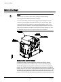
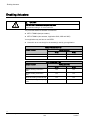
BACnet ATEC Start-up Procedures Siemens Industry, Inc. Table of contents Before You Begin ......................................................................................4 Setting Controller Address ....................................................................... 5 Setting the Application .............................................................................5 Enabling Actuators ...................................................................................6 Specifying Motor Setup ............................................................................................. 7 Verifying Actuator Setup ............................................................................................ 7 Setting Number of Heat Stages ................................................................ 7 Selecting Automatic Calibration Option .................................................. 8 Setting Room Temperature Setpoints ..................................................... 9 Configuring the Room Unit .................................................................... 10 Setting Override Time ............................................................................. 10 Configuring Universal Inputs (UIs) ........................................................ 10 Enabling Wall Switch .............................................................................. 11 Setting Duct Area .................................................................................... 11 Setting Flow Coefficient ......................................................................... 12 Setting Flow Sensor Factors .................................................................. 13 Setting Airflow Setpoints........................................................................ 14 Setting Room Temperature Offset (optional) ........................................ 15 Configuring BACnet Parameters ........................................................... 16 3 Siemens Industry, Inc. 140-0893 Start-up Draft 1/12/2010 Before You Begin Before You Begin NOTE: WCIS version 3.0 or later must be used to configure Siemens Building Technologies BACnet MS/TP Equipment Controllers. Do not check the Metric checkbox in the Device Properties dialogue box if the controller is communicating through the MS/TP driver in the field panel. Metric can be checked only if the controller is communicating through a router. If you need metric and the controller is communicating through the MS/TP driver in the field panel, then the Metric checkbox in the Device Properties dialogue box must be unchecked and the conversion must be handled in the field panel. Communication and DO Indicators The BACnet Actuating Terminal Equipment Controller has LEDs to indicate communication (yellow) and DO (digital output, if present) status BST (green). The RX LED will flash for data packets received by the actuator from the MS/TP network. The TX LED will flash for data packets sent by the actuator to the MS/TP network. Each DO (3 to 5) has an associated LED located above its termination point. This LED point is on when the associated DO is commanded ON otherwise, it is OFF. The BACnet Actuator will attempt to communicate with other devices as soon as it powers up. The TX LED will start flashing as it attempts to connect and transfer data. 4 Siemens Industry, Inc. 140-0893 Start-up Draft 1/12/2010 Setting Controller Address Setting Controller Address Set CTLR ADDRESS to the BACnet MS/TP MAC address. (0 through 127 = Master; 128 through 254 = Slave). NOTE: Set the controller address and MS/TP network baud rate prior to connecting the controller to the network. See Configuring BACnet Parameters [ 16]. Setting the Application Add the TEC to your job database and select one of the following applications. Application Description Application Number VAV Cooling Only 2860 VAV Cooling or Heating 2861 VAV with Electric Reheat or Baseboard Radiation 2862 VAV with Hot Water Reheat 2863 VAV Series Fan Powered with Electric Reheat 2864 VAV Series Fan Powered with Hot Water Reheat 2865 VAV Parallel Fan Powered with Electric Reheat 2866 VAV Parallel Fan Powered with Hot Water Reheat 2867 VAV Slave Mode 2897 After you set the application, sensor altitude, tubing length, tubing internal diameter, UI1 and UI2 configuration point, the controller goes through a shut-down/load sequence as it switches from slave mode to the application selected. After the application loads, the calibration cycle begins. At the start of the calibration cycle, the controller automatically sets CAL AIR to YES. When the cycle is complete, CAL AIR returns to NO. The air velocity sensor calibration cycle begins within three minutes of an application start-up or initialization, depending on the controller’s address. After this delay, the calibration cycle takes from 2 to 5 minutes to complete. The air damper closes during calibration. NOTE: You can continue the startup procedure while calibration is underway. However, the controller will ignore commands to control end devices (such as the damper) until calibration of the air velocity sensor is finished. 5 Siemens Industry, Inc. 140-0893 Start-up Draft 1/12/2010 Enabling Actuators Enabling Actuators CAUTION The controller's DOs control only 24 Vac loads. The maximum rating is 12 VA for each DO. The points that determine actuator run times are: MTR 1 TIMING (damper acutator) MTR 2 TIMING (valve actuator, Application 2863, 2865 and 2867) Your application may not have or use MTR2. Use and/or to set run time(s) for the actuator(s) used by your application. Damper Actuator Run Time Damper Actuator Setting (seconds) 50 Hz 60 Hz GDE131.1 125 90 GLB131.1 150 125 Valve Actuator Run Time Damper Actuator Setting (seconds) 50 Hz 60 Hz SSB81U, floating control fail in place 180 150 SSC81U, floating control fail in place 150 125 SSC81.5U, floating control fail-safe 125 125 SQS85.53U, floating control spring return 35 30 6 Siemens Industry, Inc. 140-0893 Start-up Draft 1/12/2010 Setting Number of Heat Stages Specifying Motor Setup MTR SETUP determines which actuators are controlled by the application and whether they are direct or reverse acting. Set MTR SETUP according to Table MTR SETUP Values. NOTE: When MTR SETUP is changed, all enabled actuators will calibrate. Wait until each actuator has completed its calibration before continuing. MTR SETUP Values Motor 1 (Damper) Motor 2 Enabled Enabled and Reversed Not Used 1 (default) 3 Enabled 5 7 Enabled and Reversed 13 15 Verifying Actuator Setup 1. Command all actuators closed. Verify that they close and remain closed. If not, adjust the setting for MTR SETUP according to Table MTR SETUP Values. 2. If any of the actuators still do not close completely, then the actuators have been installed or set up incorrectly. See the installation instructions (550-031), the iKnow Troubleshooting Tool, or contact Field Support. Setting Number of Heat Stages Depending on the application, HTG STG CNT (if present) refers to electric heat stages used (enabled), some point names may vary. For electric heat applications, check the hardware to verify the number of electric heat stages wired to the controller (1 to 3 stages without fan or 1 to 2 stages with fan) and set HTG STG CNT to this value. CAUTION For installations using electric heat coils, never set min airflow settings to 0. Equipment damage can occur if electric heat is on without airflow. 7 Siemens Industry, Inc. 140-0893 Start-up Draft 1/12/2010 Selecting Automatic Calibration Option Selecting Automatic Calibration Option Using Table CAL SETUP Options set CAL SETUP to the value that best meets your job requirements. If appropriate, change CAL TIMER from the default of 12 hours. This setting applies only if your choice for CAL SETUP includes Option 4. NOTE: The air velocity sensor should be calibrated at least once every 24 hours. Make sure that the sensor has been calibrated before balancing takes place, as this will affect the balancer’s results. CAL SETUP Options CAL SETUP Description 0 Calibration occurs ONLY when the point CAL AIR is set to YES. 1 Calibration occurs when the field panel commands a day/night mode changeover. Actual calibration is subject to a time delay of 0, 1, 2, or 3 minutes. This delay is determined by the point CTLR ADDRESS divided by 4. The remainder is the time delay in minutes. For example, If CTLR ADDRESS = 11, then the controller will wait 3 minutes (11 ÷ 4 = 2 R3) after it receives the day/night mode changeover command before beginning the calibration routine. 2 Calibration occurs immediately after the override switch is depressed. 4 (factory default value) Calibration occurs on the time interval set in the point CAL TIMER. For example, if CAL TIMER = 12, then the calibration period is 12 hours. Actual calibration is subject to a time delay based on the value of CTLR ADDRESS. See the example in Option 1. NOTE: Options can be combined by summing their numbers. For example, to calibrate as in Options 1 and 2, set CAL SETUP to 3. 8 Siemens Industry, Inc. 140-0893 Start-up Draft 1/12/2010 Setting Room Temperature Setpoints Setting Room Temperature Setpoints Day (or occupied) cooling setpoint: DAY CLG STPT Day (or occupied) heating setpoint: DAY HTG STPT Night (or unoccupied) cooling setpoint: NGT CLG STPT Night (or unoccupied) heating setpoint: NGT HTG STPT 1. If the room temperature sensor has a setpoint dial that will be used, set STPT DIAL to YES. Otherwise, set STPT DIAL to NO. − Set RM STPT MIN and RM STPT MAX for the minimum and maximum allowable room temperature setpoint values, respectively. Valid values range from 55° to 95°F (13° to 35°C). Default values are 55°F (13°C) for RM STPT MIN and 90°F (32°C) for RM STPT MAX. 2. Setpoint dial configured with a heating/cooling deadband (default). − To allow the controller to operate with a heating/cooling deadband (functioning the same as provided when the setpoint dial is not present) the following configuration should be used. − Set the DAY HTG STPT less than the DAY CLG STPT by the deadband (or zero energy band) that is desired. (for example, DAY HTG STPT = 70°F; DAY CLG STPT = 74°F, providing a deadband of 4 degrees). Only the difference between these values is used to determine the setpoint that will be used. − As described below, the setpoint(s) for heating/cooling will be 1/2 of the deadband above or below the setpoint dial value. When HEAT.COOL equals HEAT, then: CTL STPT will equal RM STPT DIAL – 0.5 * (DAY CLG STPT – DAY HTG STPT) and will be limited by RM STPT MIN and RM STPT MAX. When HEAT.COOL equals COOL, then: CTL STPT will equal RM STPT DIAL + 0.5 * (DAY CLG STPT – DAY HTG STPT) and will be limited by RM STPT MIN and RM STPT MAX. NOTE: A space where the deadband is used can be more energy efficient than a space where the deadband is not being used 3. Setpoint dial configured for zero heating/cooling deadband. − When the job specification requires a common heating and cooling temperature setpoint, the following configuration should be used. − Set DAY HTG STPT equal to DAY CLG STPT. This will configure the setpoint deadband equal to zero. − In addition, when a setpoint deadband equals zero, then: − CTL STPT will equal RM STPT DIAL, and will be limited by RM STPT MIN and RM STPT MAX. NOTE: A space where the heating/cooling deadband is zero may be more 9 Siemens Industry, Inc. 140-0893 Start-up Draft 1/12/2010 Configuring the Room Unit comfortable than a space where the deadband is being used, but may use more energy. 4. Set the room temperature setpoints to the desired values. Heating setpoints are not present in cooling only applications.) Configuring the Room Unit STAT SUPV values are additive; set STAT SUPV to the sum of the configured selection. A value of 3 indicates the stat has both humidity and temperature.. 0 - for the Sensing only Room Unit. 1 - for communicating Room Unit with Full featured Room Unit. 2 - for communicating Room Unit with humidity. Setting Override Time If using night/unoccupied override, set OVRD TIME to the number of whole hours that an override should last. If OVRD TIME equals 0 (default), this feature is disabled. Configuring Universal Inputs (UIs) Configure each Universal Input; using one of the following options for each UI. (UI1 CFG, UI 2 CFG) 0 - DI 1 - 10K (Temperature thermister) 2 - 0-10V (0 to 100%) 3 - 4-20mA (0 to 100%) NOTE: The controller goes through a shut-down/load sequence after setting. 10 Siemens Industry, Inc. 140-0893 Start-up Draft 1/12/2010 Enabling Wall Switch Enabling Wall Switch If a wall switch is used for day/night control, enable it by setting WALL SWITCH to YES. In addition, UI 2 must be configured for digital input (set to 0). Otherwise, leave WALL SWITCH at its default value of NO. If WALL SWITCH is not enabled, UI 2 can be used as a Spare (Analog or Digital). Setting Duct Area If provided, enter the duct area (sq ft or sq m) into DUCT AREA (and also into HTGDUCT AREA, where applicable) and continue to Setting Flow Coefficient. If you do not know the duct area, use the following table: Area = Round Duct Rectangular Duct Area in Sq. Ft. (Dimensions in inches) (π x R2)/144 Width x Height ∕144 Area in Sq. M (Dimensions in centimeters) (π x R2)/10,000 Width x Height∕10,000 11 Siemens Industry, Inc. 140-0893 Start-up Draft 1/12/2010 Setting Flow Coefficient Setting Flow Coefficient 1. Set FLOW COEFF to the appropriate value found in Table Box Manufacturer Flow Coefficients. This value is a starting point for the air balancer. 2. To fine tune the flow coefficient use the following formula: new flow coefficient = (actual volume/controller volume) x old flow coefficient The actual volume is the actual value obtained from the balancer’s measurements. The controller volume is the value obtained from AIR VOLUME. 3. If the controller volume is not within 5% of the actual volume, repeat the procedure until it is within 5%. Box Manufacturer Flow Coefficients Manufacturer Sensor Type Value Anemostat 2-pipe without orifice 2-pipe with orifice Spider without orifice Spider with orifice 0.79 0.59 0.73 0.39 Carnes 2-pipe Flow cross 0.66 0.59 Carrier 0.59 E.H. Price / Siemens Building Technologies Lab Terminal Boxes 0.78 Environmental Technologies 0.79 Krueger 0.68 Metal Aire 0.72 Nailor Industries 0.69 Titus 0.60 Trane 0.66 12 Siemens Industry, Inc. 140-0893 Start-up Draft 1/12/2010 Setting Flow Sensor Factors Setting Flow Sensor Factors The BACnet ATEC models 2301 and 0001 use mass airflow sensors to measure duct differential pressure. A differential pressure calibrated sensor is used over mass flow to make the sensor compatible with previous controller designs. Since the flow measurement is done based on the mass of the air, the BACnet ATEC has several new parameters that can/should be adjusted to help reduce airflow measurement errors. The new setup points are: (1) altitude, AIR ALTITUDE, [default is 700 feet], (2) airflow pickup to airflow sensor total tubing length, TUBE LEN, (to and from pickup) [default is 6 feet] (3) inside tubing diameter, TUBE DIAMETE, [default is 187 inches]. If you only set one of these parameters, it should be the installed altitude of the controller. This single parameter adds the most effect on sensor error. NOTE: The controller goes through a shut-down/load sequence after setting. Typical correction factor applied to sensor output. 13 Siemens Industry, Inc. 140-0893 Start-up Draft 1/12/2010 Setting Airflow Setpoints Setting Airflow Setpoints NOTE: Maximum flow(s) must be set ≥ minimum flow(s). 1. Set CLG FLOW MIN to the desired minimum cooling airflow setpoint. 2. Set CLG FLOW MAX to the desired maximum cooling airflow setpoint. Application 2861 through 2867 3. Set HTG FLOW MIN to the desired minimum heating airflow setpoint. 4. Set HTG FLOW MAX to the desired maximum heating airflow setpoint. 5. Set FLOW START to the heating loopout percentage that the flow will start to modulate in the heating mode. (that is, at HTG FLOW MIN). 6. Set FLOW END to the heating loop out percentage that the flow will end modulation (that is, at HTG FLOW MAX). In addition to the flow setpoints in the heating mode (HTG FLOW MIN and HTG FLOW MAX), the parameters FLOW START (default is 0) and FLOW END (default is 100) will determine what portion of the HTG LOOPOUT the flow will modulate the heating mode. CAUTION: If FLOW START equals FLOW END, the flow will not modulate even if HTG FLOW MAX is greater than HTG FLOW MIN. NOTE: For Applications 2862, 2863, 2864 and 2866, HTG FLOW MAX should be less than CLG FLOW MAX. Otherwise, cold supply air may cool rather than heat the space in heating mode. A typical setting for HTG FLOW MAX is 50% or less of CLG FLOW MAX. CAUTION For electric heating coils in the air terminal unit without a terminal fan, do not set HTG FLOW MIN to 0. Equipment damage may occur if insufficient air flow is present with electric heat ON. 14 Siemens Industry, Inc. 140-0893 Start-up Draft 1/12/2010 Setting Room Temperature Offset (optional) Setting Room Temperature Offset (optional) When the room has stabilized, take a precision temperature reading over a period of time at the room temperature sensor, record any difference between this reading and the value of ROOM TEMP and set this difference value (to the nearest 0.25°F (0.14°C)) into RMTMP OFFSET. Example If the actual room temperature is 72.0°F (22.2°C), and the value of ROOM TEMP is 73.0°F (23.8°C), then the value entered into RMTMP OFFSET is –1.0. In this case, the value of ROOM TEMP would read the raw value 73.0°F (23.8°C), but the value of CTL TEMP would read 72.0°F (22.2°C). CTL TEMP = ROOM TEMP + RMTMP OFFSET 15 Siemens Industry, Inc. 140-0893 Start-up Draft 1/12/2010 Configuring BACnet Parameters NOTE: WCIS version 3.0 or later must be used to configure Siemens Building Technologies BACnet MS/TP Equipment Controllers. Do not check the Metric checkbox in the Device Properties dialogue box if the controller is communicating through the MS/TP driver in the field panel. Metric can be checked only if the controller is communicating through a router. If you need metric and the controller is communicating through the MS/TP driver in the field panel, then the Metric checkbox in the Device Properties dialogue box must be unchecked and the conversion must be handled in the field panel. Using WCIS, do the following: 1. From the Device menu, select Device Properties to configure BACnet parameters. − Object Name – unique to BACnet network, (12 character RAD50 limit). − Object ID – unique to BACnet network, valid values are 0 through 4,194,303. − Description – description of controller (60 character limit). − Location – physical location of controller (60 character limit). − MSTP Network Baud Rate – options; 9600, 19200, 38400 or 76800, default is19200. 2. Configuring the Room Unit port. − If using a sensing only Room Unit, the baud rate can be 1200 to 76800. For optimal use with WCIS use 38400. − If using a communicating Room Unit, the baud rate must be set to 1200. 3. Press the Write button. The controller accepts the configuration values and then resets. When the BACnet MS/TP TEC is successfully installed, the RX and TX LEDs flash On/Off rapidly and continuously. The startup is complete upon completion of BACnet parameters configuration. Issued by Siemens Industry, Inc. Building Technologies Division 1000 Deerfield Parkway Buffalo Grove, IL 60089, USA Tel. +1 847-215-1000 Document ID 140-0893, Rev AA Edition 1/12/2010 © 2010 Copyright Siemens Industry, Inc. Technical specifications and availability subject to change without notice. Manual BACnetATEC Start-up Procedures Draft Register