1
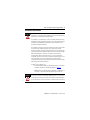
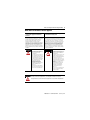
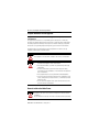
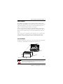
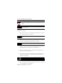
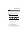
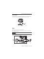
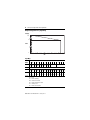
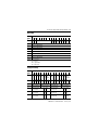
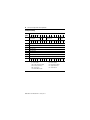
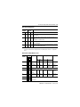
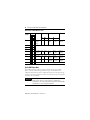
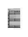
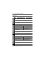
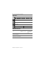
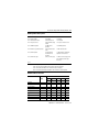
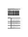
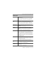
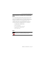
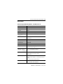
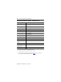
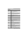
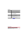
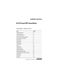
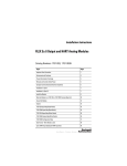
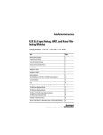
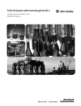
Installation Instructions
FLEX I/O 8 Output HART Analog Module
Catalog Number 1794-OE8H, Series B
Topic
Page
Important User Information
2
European Hazardous Location Approval
6
Environment and Enclosure
3
Prevent Electrostatic Discharge
4
North American Hazardous Location Approval
5
About the Module
7
Install the Module
7
Wire the Module
9
Ground the Module
11
Input Map
12
Configuration Map
13
Cyclic HART Input Data
16
Configuration Map (Series A Mode)
22
Extended Configuration Data Table (Series A Mode)
23
Field Descriptions
24
Status Indicators
28
Specifications
29
2 FLEX I/O 8 Output HART Analog Module
Important User Information
Solid state equipment has operational characteristics differing from those of electromechanical equipment.
Safety Guidelines for the Application, Installation and Maintenance of Solid State Controls (Publication
SGI-1.1 available from your local Rockwell Automation sales office or online at
http://literature.rockwellautomation.com) describes some important differences between solid state
equipment and hard-wired electromechanical devices. Because of this difference, and also because of the
wide variety of uses for solid state equipment, all persons responsible for applying this equipment must
satisfy themselves that each intended application of this equipment is acceptable.
In no event will Rockwell Automation, Inc. be responsible or liable for indirect or consequential damages
resulting from the use or application of this equipment.
The examples and diagrams in this manual are included solely for illustrative purposes. Because of the
many variables and requirements associated with any particular installation, Rockwell Automation, Inc.
cannot assume responsibility or liability for actual use based on the examples and diagrams.
No patent liability is assumed by Rockwell Automation, Inc. with respect to use of information, circuits,
equipment, or software described in this manual.
Reproduction of the contents of this manual, in whole or in part, without written permission of Rockwell
Automation, Inc., is prohibited.
Throughout this manual, when necessary, we use notes to make you aware of safety considerations.
WARNING
IMPORTANT
ATTENTION
Identifies information about practices or circumstances that can cause an explosion in
a hazardous environment, which may lead to personal injury or death, property
damage, or economic loss.
Identifies information that is critical for successful application and understanding of
the product.
Identifies information about practices or circumstances that can lead to personal
injury or death, property damage, or economic loss. Attentions help you identify a
hazard, avoid a hazard and recognize the consequences.
SHOCK HAZARD
Labels may be on or inside the equipment (for example, drive or motor) to alert people
that dangerous voltage may be present.
BURN HAZARD
Labels may be on or inside the equipment (for example, drive or motor) to alert people
that surfaces may reach dangerous temperatures.
Publication 1794-IN109D-EN-P - January 2014
FLEX I/O 8 Output HART Analog Module 3
Environment and Enclosure
ATTENTION
This equipment is intended for use in a Pollution Degree 2 industrial
environment, in overvoltage Category II applications (as defined in IEC 60664-1),
at altitudes up to 2000 m (6562 ft) without derating.
This equipment is considered Group 1, Class A industrial equipment according
to IEC/CISPR 11. Without appropriate precautions, there may be difficulties with
electromagnetic compatibility in residential and other environments due to
conducted and radiated disturbances.
This equipment is supplied as open-type equipment. It must be mounted within
an enclosure that is suitably designed for those specific environmental
conditions that will be present and appropriately designed to prevent personal
injury resulting from accessibility to live parts. The enclosure must have suitable
flame-retardant properties to prevent or minimize the spread of flame,
complying with a flame spread rating of 5VA, V2, V1, V0 (or equivalent) if
non-metallic. The interior of the enclosure must be accessible only by the use of
a tool. Subsequent sections of this publication may contain additional
information regarding specific enclosure type ratings that are required to comply
with certain product safety certifications.
In addition to this publication, see:
• Industrial Automation Wiring and Grounding Guidelines, for additional
installation requirements, Allen-Bradley publication 1770-4.1.
• NEMA Standards 250 and IEC 60529, as applicable, for explanations of
the degrees of protection provided by different types of enclosure.
WARNING
If you insert or remove the module while backplane power is on, an electrical
arc can occur. This could cause an explosion in hazardous location installations.
Be sure that power is removed or the area is nonhazardous before proceeding.
Publication 1794-IN109D-EN-P - January 2014
4 FLEX I/O 8 Output HART Analog Module
ATTENTION
This product is grounded through the DIN rail to chassis ground. Use zinc plated
yellow-chromate steel DIN rail to assure proper grounding. The use of other DIN
rail materials (for example, aluminum or plastic) that can corrode, oxidize, or are
poor conductors, can result in improper or intermittent grounding. Secure DIN
rail to mounting surface approximately every 200 mm (7.8 in.) and use
end-anchors appropriately.
Prevent Electrostatic Discharge
ATTENTION
ATTENTION
This equipment is sensitive to electrostatic discharge, which can cause internal
damage and affect normal operation. Follow these guidelines when you handle
this equipment:
• Touch a grounded object to discharge potential static.
• Wear an approved grounding wriststrap.
• Do not touch connectors or pins on component boards.
• Do not touch circuit components inside the equipment.
• Use a static-safe workstation, if available.
• Store the equipment in appropriate static-safe packaging when not in
use.
To comply with the CE Low Voltage Directive (LVD), all connected I/O must be
powered from a source compliant with the following:
Safety Extra Low Voltage (SELV) or Protected Extra Low Voltage (PELV).
Publication 1794-IN109D-EN-P - January 2014
FLEX I/O 8 Output HART Analog Module 5
North American Hazardous Location Approval
The following information applies when
operating this equipment in hazardous
locations:
Informations sur l’utilisation de cet équipement
en environnements dangereux:
Products marked "CL I, DIV 2, GP A, B, C, D" are suitable
for use in Class I Division 2 Groups A, B, C, D, Hazardous
Locations and nonhazardous locations only. Each
product is supplied with markings on the rating
nameplate indicating the hazardous location
temperature code. When combining products within a
system, the most adverse temperature code (lowest "T"
number) may be used to help determine the overall
temperature code of the system. Combinations of
equipment in your system are subject to investigation
by the local Authority Having Jurisdiction at the time of
installation.
Les produits marqués “CL I, DIV 2, GP A, B, C, D” ne
conviennent qu’à une utilisation en environnements de Classe I
Division 2 Groupes A, B, C, D dangereux et non dangereux.
Chaque produit est livré avec des marquages sur sa plaque
d’identification qui indiquent le code de température pour les
environnements dangereux. Lorsque plusieurs produits sont
combinés dans un système, le code de température le plus
défavorable (code de température le plus faible) peut être
utilisé pour déterminer le code de température global du
système. Les combinaisons d’équipements dans le système
sont sujettes à inspection par les autorités locales qualifiées
au moment de l’installation.
WARNING
EXPLOSION HAZARD • Do not disconnect equipment
unless power has been removed or
the area is known to be
nonhazardous.
• Do not disconnect connections to
this equipment unless power has
been removed or the area is known
to be nonhazardous. Secure any
external connections that mate to
this equipment by using screws,
sliding latches, threaded
connectors, or other means
provided with this product.
• Substitution of components may
impair suitability for Class I,
Division 2.
• If this product contains batteries,
they must only be changed in an
area known to be nonhazardous.
ATTENTION
AVERTISSEMENT
RISQUE D’EXPLOSION –
• Couper le courant ou s’assurer que
l’environnement est classé non
dangereux avant de débrancher
l'équipement.
• Couper le courant ou s'assurer que
l’environnement est classé non
dangereux avant de débrancher les
connecteurs. Fixer tous les
connecteurs externes reliés à cet
équipement à l'aide de vis, loquets
coulissants, connecteurs filetés ou
autres moyens fournis avec ce
produit.
• La substitution de composants
peut rendre cet équipement
inadapté à une utilisation en
environnement de Classe 1,
Division 2.
• S’assurer que l’environnement est
classé non dangereux avant de
changer les piles.
For Class I Division 2 applications, use only Class I Division 2 Listed or
Recognized accessories and modules approved for use within 1794 platform.
Publication 1794-IN109D-EN-P - January 2014
6 FLEX I/O 8 Output HART Analog Module
European Hazardous Location Approval
European Zone 2 Certification (The following applies when the product bears the Ex
or EEx Marking.)
This equipment is intended for use in potentially explosive atmospheres as defined by
European Union Directive 94/9/EC and has been found to comply with the Essential Health
and Safety Requirements relating to the design and construction of Category 3 equipment
intended for use in potentially explosive atmospheres, given in Annex II to this Directive.
Compliance with the Essential Health and Safety Requirements has been assured by
compliance with EN 60079-15 and EN 60079-0.
ATTENTION
This equipment is not resistant to sunlight or other sources of UV radiation.
WARNING
• This equipment must be installed in an enclosure providing at least IP54
protection when applied in Zone 2 environments.
• This equipment shall be used within its specified ratings defined by
Allen-Bradley.
• Provision shall be made to prevent the rated voltage from being
exceeded by transient disturbances of more than 40% when applied in
Zone 2 environments.
• This equipment must be used only with ATEX certified backplanes.
• Secure any external connections that mate to this equipment by using
screws, sliding latches, threaded connectors, or other means provided
with this product.
• Do not disconnect equipment unless power has been removed or the
area is known to be nonhazardous.
Removal and Insertion Under Power
WARNING
When you insert or remove the module while backplane power is on, an
electrical arc can occur. This could cause an explosion in hazardous location
installations.
Be sure that power is removed or the area is nonhazardous before proceeding.
Publication 1794-IN109D-EN-P - January 2014
FLEX I/O 8 Output HART Analog Module 7
About the Module
The HART analog modules can be used with ControlNet, Ethernet and
Profibus-DP (1794-APBDV1 only) adapters. When using the Series B module
with a Series B profile, you must have a ControlNet adapter Revision 5.1 or
higher or an Ethernet adapater Revision 4.2 or higher.
For this scenario (Series A profile with a Series B Module), the data maps
(input, configuration and extended configuration) are designated as Series A
Mode. Note, all other data maps are for a Series B module with a Series B
profile.
Only use the series A configuration when replacing a series A module with a
series B module. If you access the Series A configuration while using the
module as a series B unpredictably operation of the module may occur.
Install the Module
Read this for information about how to install the module. The module must
be used with a 1794-TB3G or 1794-TB3GS terminal base unit.
7
3
1
8
2
6
4
5
40231
Label here or under here
ATTENTION
During mounting of all devices, be sure that all debris (such as metal chips or
wire strands) is kept from falling into the module. Debris that falls into the
module could cause damage on power up.
Publication 1794-IN109D-EN-P - January 2014
8 FLEX I/O 8 Output HART Analog Module
ATTENTION
IMPORTANT
Do not remove or replace a Terminal Base unit while power is applied.
Interruption of the backplane can result in unintentional operation or machine
motion.
You must disable keying in your profile when replacing a series A module with
a series B module.
To install the module on a 1794 terminal base, refer to the figure and
complete the following.
1. Rotate the keyswitch (1) on the terminal base (2) clockwise to position
4 as required for this type of module.
IMPORTANT
Do not change the position of the keyswitch after wiring the terminal base
unit.
2. Make sure the flexbus connector (3) is pushed all the way to the left to
connect with the neighboring terminal base or adapter.
IMPORTANT
You cannot install the module unless the connector is fully extended.
3. Make sure the pins on the bottom of the module are straight so they
align properly with the connector in the terminal base.
4. Position the module (4) with its alignment bar (5) aligned with the
groove (6) on the terminal base.
5. Press firmly and evenly to seat the module in the terminal base unit,
noting that the module is seated when the latching mechanism (7) is
locked into the module.
41307
6. Remove cap plug (8) and attach another terminal base unit to the right
of this terminal base unit if required.
Publication 1794-IN109D-EN-P - January 2014
FLEX I/O 8 Output HART Analog Module 9
Wire the Module
If you connect or disconnect wiring while the field-side power is on, an
electrical arc can occur. This could cause an explosion in hazardous location
installations. Be sure that power is removed or the area is nonhazardous before
proceeding.
WARNING
To connect two-wire transmitter devices for 1794-TB3G and 1794-TB3GS
bases, refer to the tables and figure and complete the following.
Module Wiring
0
1
2
3
4
+ _
17
Chassis
Ground
7
8
19
20
21
+ _
23
24
25
(COM)
NC
37
38
39
11
12
41
42
14
15
A
Ch3
26
27
28
29
43
30
31
32
33
B
+ _
Ch6
40
13
+ _
+ _
Ch5
36
10
Ch2
22
+ _
35
9
+ _
Ch1
18
Ch4
34
6
+ _
Ch0
16
5
Chassis
Ground
Ch7
44
45
46
47
48
49
50
51
NC
+V
(COM)
C
+V
24V DC
Supply In
Chassis Grounds
+V
= +24V DC = Terminals C-34 and C-50
-V
= COM
= C-35 and C-51
Chassis Ground
= Terminals B-16, B-33, C-38, C-40…45, and C-47
NC
= No connection
For daisy-chaining : Supply in C-34 (+V) and C-35 (COM)
Supply out C-50 (+V) and C-51 (COM)
24V DC
Supply Out
(1794-TB3G shown)
44864
1. Connect the individual input wiring to (+) terminals (0, 4, 8, 12) on
the 0 to 15 row (A) and on the 16 to 33 row (B) (terminals 17, 21, 25,
29) as indicated in the table Wire Connections.
2. Connect the associated input to the corresponding (-) terminal (1, 5,
9, 13) on the 0 to 15 row (A), and on the 16 to 33 row (B) (terminals
18, 22, 26, 30) for each input as indicated in the table Wire
Connections.
3. Connect +V DC power to terminal 34 on the 34 to 51 row (C).
Publication 1794-IN109D-EN-P - January 2014
10 FLEX I/O 8 Output HART Analog Module
4. Connect -V to terminal 35 on the 34 to 51 row (C).
5. If continuing power to the next terminal base unit, connect a jumper
from terminal 50 (+V) on this base unit to terminal 34 on the next
base unit.
If continuing common to the next terminal base unit, connect a
jumper from terminal 51 (-V) on this base unit to terminal 35 on the
next base unit.
ATTENTION
ATTENTION
The 1794-OE8H module shall be used only with Listed Allen-Bradley (Rockwell
Automation) Power Supply (catalog number 1794-PS13) or Listed Class 2 source.
To reduce susceptibility to noise, power analog modules and digital modules
from separate power supplies.
Wire Connections
Output
Output +
Output -
Output
Output +
Output -
Output 0
A-0
A-1
Output 4
B-17
B-18
Output 1
A-4
A-5
Output 5
B-21
B-22
Output 2
A-8
A-9
Output 6
B-25
B-26
Output 3
A-12
A-13
Output 7
B-29
B-30
+V
Terminals 34 and 50
-V
Terminals 35 and 51
Terminals B-16, B-33, C-38, C-40, C-41, C-43, C-43, C-44, C-45 and C-48 are connected to
chassis ground
Publication 1794-IN109D-EN-P - January 2014
FLEX I/O 8 Output HART Analog Module 11
Ground the Module
All I/O wiring must use shielded wire. Shields must be terminated external to
the module, such as bus bars and shield-terminating feed-throughs.
44862
Outputs
Each output can operate an analog field device.
The channels in these modules are electrically connected to each other and
have a common plus-line.
IMPORTANT
When interconnecting several lines, you must consider the total accumulated
power.
250 Ω
1794-OE8H/B
+V
Power Supply
21.6 V
FlexBus
-V
4...20 mA
+
Bus
I
uC
HART
Modem
45 Ω
F
sig
4...20 mA
43849
Publication 1794-IN109D-EN-P - January 2014
12 FLEX I/O 8 Output HART Analog Module
Output Voltage/Currency Capability
Voltage
20.5
15
V DC
0
0
5
10
15
mA
20
43850
25
Input Map
Bit
Word
15
0
FA FA FA FA FA FA FA FA HR Reserved
Ch7 Ch6 Ch5 Ch4 Ch3 Ch2 Ch1 Ch0
14
13
12
11
10
9
8
7
6
5
4
3
2
1
0
Diagnostic Status
1
Reserved
2
HCF HCF HCF HCF HCF HCF HCF HCF HF HF HF HF HF HF HF HF
Ch7 Ch6 Ch5 Ch4 Ch3 Ch2 Ch1 Ch0 Ch7 Ch6 Ch5 Ch4 Ch3 Ch2 Ch1 Ch0
3
HP HP HP HP HP HP HP HP HC HC HC HC HC HC HC HC
Ch7 Ch6 Ch5 Ch4 Ch3 Ch2 Ch1 Ch0 Ch7 Ch6 Ch5 Ch4 Ch3 Ch2 Ch1 Ch0
Where: Ch = channel
FA = fault
HR = HART rebuilding
HCF = HART current fault
HF = HART communication fault
HP = HART present
HC = HART communication
Publication 1794-IN109D-EN-P - January 2014
FLEX I/O 8 Output HART Analog Module 13
Output Map
Bit
Word
15
0
Res FR
14
13
12
11
1
Channel 0 Output Data
2
Channel 1 Output Data
3
Channel 2 Output Data
4
Channel 3 Output Data
5
Channel 4 Output Data
6
Channel 5 Output Data
7
Channel 6 Output Data
8
Channel 7 Output Data
10
9
8
7
Reserved
6
5
4
3
2
1
0
DD DD DD DD DD DD DD DD
Ch7 Ch6 Ch5 Ch4 Ch3 Ch2 Ch1 Ch0
Where: Res = reserved
Ch = channel
DD = digital data
FR = fault reset
Configuration Map
Bit
Word
15
0
LFM VR FE FE FE FE Byte
HS
HSI FE FE FE FE Byte
Ch7 Ch6 Ch5 Ch4 Order
LEDs
Ch3 Ch2 Ch1 Ch0 Order
Group B
Group A
14 13 12 11 10 9
8
7
6
5
4
3
2
1
0
1
HD HD HD HD HD HD HD HD HHE
Ch7 Ch6 Ch5 Ch4 Ch3 Ch2 Ch1 Ch0 Ch7
2
Data Format Ch3
Data Format Ch2
Data Format Ch1
Data Format Ch0
3
Data Format Ch7
Data Format Ch6
Data Format Ch5
Data Format Ch4
4
HART Read Back
Threshold Ch1
FLE AFM
Ch1 Ch1
HART Read Back
Threshold Ch0
FLE AFM
Ch0 Ch0
5
HART Read Back
Threshold Ch3
FLE AFM
Ch3 Ch3
HART Read Back
Threshold Ch2
FLE AFM
Ch2 Ch2
6
HART Read Back
Threshold Ch5
FLE AFM
Ch5 Ch5
HART Read Back
Threshold Ch4
FLE AFM
Ch4 Ch04
HHE HHE HHE HHE HHE HHE HHE
Ch6 Ch5 Ch4 Ch3 Ch2 Ch1 Ch0
Publication 1794-IN109D-EN-P - January 2014
14 FLEX I/O 8 Output HART Analog Module
Configuration Map
Bit
Word
15
7
HART Read Back
Threshold Ch7
14 13 12 11 10 9
8
8
DF DF DF DF DF DF DF DF DM
Ch7 Ch6 Ch5 Ch4 Ch3 Ch2 Ch1 Ch0 Ch7
FLE AFM
Ch7 Ch7
7
9
Fault Value Ch0
10
Fault Value Ch1
11
Fault Value Ch2
12
Fault Value Ch3
13
Fault Value Ch4
14
Fault Value Ch5
15
Fault Value Ch6
16
Fault Value Ch7
17
HR HR HR HR HR HR HR HR HC
Ch7 Ch6 Ch5 Ch4 Ch3 Ch2 Ch1 Ch0 Ch7
Where
LFM = local fault mode
FE = fault enable
HHE = HART handheld enable
AFM = analog fault mode
DM = digital mode
HC = HART CMD3 disable
Publication 1794-IN109D-EN-P - January 2014
6
5
HART Read Back
Threshold Ch6
4
3
2
1
0
FLE AFM
Ch6 Ch06
DM DM DM DM DM DM DM
Ch6 Ch5 Ch4 Ch3 Ch2 Ch1 Ch0
HC HC HC HC HC HC HC
Ch6 Ch5 Ch4 Ch3 Ch2 Ch1 Ch0
VR = verify replacement
HD = HART disable
FLE = fault latch enabled
DF = digital fault mode
HR = HART rebuild
FLEX I/O 8 Output HART Analog Module 15
Byte Order Configuration
Byte Order Byte Order Description(1)
Group B
Group A
Bit 9 Bit 8 Bit 1 Bit 0
0
0
0
0
Little Endian Format (Default) = All data entries in true little
Endian format.
1
0
1
0
Word Swap = Word swap only values requiring more then one
word,
for example: 32 bit float values.
0
1
0
1
Byte Swap (reserved for future implementation) = Byte swap all
words in data table.
1
1
1
1
Big Endian Format (reserved for future implementation) = All data
entries in true Big Endian format.
(1)
All other combinations are invalid. Values will Revert to the last valid configuration (in case of original
start-up this would be default configuration) and set module Diagnostic Status to "2" configuration
failure.
Data Format - Write Words 2 and 3
Data
Format
Bits
15
11
7
3
14
10
6
2
Format
13
9
5
1
12
8
4
0
Signal Range User Range
LO
HI
LO
Resolution
HI
0
0 0 0 0 0…20 mA as 0.00
Milliamps
22.00
0
22000
0.1% of
(0.000 mA) (22.000 mA) 0...20 mA
1
0 0 0 1 0…20 mA as 0.00
%
22.00
0
(0%)
2
0 0 1 0 Not assigned
3
0 0 1 1 0…20 mA as 0.00
unsigned
integer
20.00
0
65535
0.03% of
(0.000 mA) (22.000 mA) 0...20 mA
4
0 1 0 0 4…20 mA as 2.00
mA
22.00
2000
22000
0.01% of
(2.000 mA) (22.000 mA) 4...20 mA
5
0 1 0 1 Not assigned
6
0 1 1 0
11000
(110.00%)
0.2% of
0...20 mA
Not assigned
Publication 1794-IN109D-EN-P - January 2014
16 FLEX I/O 8 Output HART Analog Module
Data Format - Write Words 2 and 3
Data
Format
Bits
15
11
7
3
14
10
6
2
Format
13
9
5
1
12
8
4
0
Signal Range User Range
LO
Resolution
HI
LO
HI
20.00
0
(4 mA)
65535
(20 mA)
0.03% of
4...20 mA
22.00
0
(0 mA)
8000
(22 mA)
0.28% of
0...20 mA
7
0 1 1 1 4…20 mA as 4.00
unsigned
interger
8
1 0 0 0 Not assigned
9
1 0 0 1
10
1 0 1 0
11
1 0 1 1 0...20 mA as 0.00
D/A count
12
1 1 0 0 Not assigned
13
1 1 0 1 4...20 mA as 3.00
%
21.00
-625
(-6.25%)
10625
(106.25%)
0.16% of
4...20 mA
14
1 1 1 0 4...20 mA as 2.00
%
22.00
-1250
11250
(-12.50%) (112.50%)
0.16% of
4...20 mA
15
1 1 1 1 Not assigned
Cyclic HART Input Data
The HART input data holds the primary variables for the "live" HART
device, and other information gathered during the normal HART scan.
Additional "documentary" data is available through the pass through message
interface in the device information tables. Pass through messages are defined
in detail in the User Manual.
IMPORTANT
The HART Input Data for a channel may be zeroes if HART communications is
disabled for that channel. For more information on disabling HART
communications, refer to the Disable HART communications and HART CMD
3 Disable functions in the Configuration Map table.
Publication 1794-IN109D-EN-P - January 2014
FLEX I/O 8 Output HART Analog Module 17
HART Input Data
Word
Bit
0
Reserved
1
Reserved
15
14
13
12
11
10
9
8
7
6
5
4
3
2
1
0
Ch7 Ch6 Ch5 Ch4 Ch3 Ch2 Ch1 Ch0
(HART Communications Status)
2
Ch0 HART Field Device Status
Ch0 HART Comm Status
3
Reserved
Ch0 HART Loop Status
4
Ch0 HART Primary Value
(IEEE 754-1985 Single-Precision 32 bit floating point)
5
6
7
8
9
10
Ch0 HART Secondary Value
(IEEE 754-1985 Single-Precision 32 bit floating point)
Ch0 HART Tertiary Value
(IEEE 754-1985 Single-Precision 32 bit floating point)
11
Ch0 HART Fourth (Quaternary) Value
(IEEE 754-1985 Single-Precision 32 bit floating point)
12
Ch0 Secondary Value Units Code
Ch0 Primary Value Units Code
13
Ch0 Fourth Value Units Code
Ch0 Tertiary Value Units Code
14
Ch1 HART Field Device Status
Ch1 HART Communication Status
15
Reserved
Ch1 HART Loop Status
16
Ch1 HART Primary Value
17
18
Ch1 HART Secondary Value
19
20
Ch1 HART Teritiary Value
21
22
Ch1 HART Fourth Value
23
24
Ch1 HART Secondary Value Units Code
Ch1 HART Primary Value Units Code
25
Ch1 HART Fourth Value
Ch1 HART Tertiary Value Units Code
26
Ch2 HART Field Device Status
Ch2 HART Communication Status
27
Reserved
Ch2 HART Loop Status
Publication 1794-IN109D-EN-P - January 2014
18 FLEX I/O 8 Output HART Analog Module
HART Input Data
Word
Bit
15
28
14
13
12
11
10
9
8
7
6
5
4
3
2
1
Ch2 HART Primary Value
29
30
Ch2 HART Secondary Value
31
32
Ch 2 HART Tertiary Value
33
34
Ch2 HART Fourth Value
35
36
Ch2 HART Secondary Value Units Code
Ch2 HART Primary Value Units Code
37
Ch2 HART Fourth Value
Ch2 HART Tertiary Value Units Code
38
Ch3 HART Field Device Status
Ch3 HART Communication Status
39
Reserved
Ch0 HART Loop Status
40
Ch3 HART Primary Value
41
42
Ch3 HART Secondary Value
43
44
Ch3 HART Tertiary Value
45
46
Ch3 HART Fourth Value
47
48
Ch3 HART Secondary Value Units Code
Ch3 HART Primary Value Units Code
49
Ch3 HART Fourth Value
Ch3 HART Tertiary Value Units Code
50
Ch4 HART Field Device Status
Ch4 HART Communication Status
51
Reserved
Ch4 HART Loop Status
52
Ch4 HART Primary Value
53
54
Ch4 HART Secondary Value
55
56
Ch4 HART Tertiary Value
57
Publication 1794-IN109D-EN-P - January 2014
0
FLEX I/O 8 Output HART Analog Module 19
HART Input Data
Word
Bit
15
58
14
13
12
11
10
9
8
7
6
5
4
3
2
1
0
Ch4 HART Fourth Value
59
60
Ch4 HART Secondary Value Units Code
Ch4 HART Primary Value Units Code
61
Ch4 HART Fourth Value
Ch4 HART Tertiary Value Units Code
62
Ch5 HART Field Device Status
Ch5 HART Communication Status
63
Reserved
Ch5 HART Loop Status
64
Ch5 HART Primary Value
65
66
Ch5 Secondary Value
67
68
Ch5 Tertiary Value
69
70
Ch5 Fourth Value
71
72
Ch5 HART Secondary Value Units Code
Ch5 HART Primary Value Units Code
73
Ch5 HART Fourth Value
Ch5 HART Tertiary Value Units Code
74
Ch6 HART Field Device Status
CH6 HART Communication Status
75
Reserved
Ch6 HART Loop Status
76
Ch6 HART Primary Value
77
78
Ch6 Secondary Value
79
80
Ch6 Tertiary Value
81
82
Ch6 Fourth Value
83
84
Ch6 HART Secondary Value Units Code
Ch6 HART Primary Value Units Code
85
Ch6 HART Fourth Value
Ch6 HART Tertiary Value Units Code
86
Ch7 HART Field Device Status
CH7 HART Communication Status
87
Reserved
Ch7 HART Loop Status
Publication 1794-IN109D-EN-P - January 2014
20 FLEX I/O 8 Output HART Analog Module
HART Input Data
Word
Bit
15
88
14
13
12
11
10
9
8
7
6
5
4
3
2
1
0
Ch7 HART Primary Value
89
90
Ch7 Secondary Value
91
92
Ch7 Tertiary Value
93
94
Ch7 Fourth Value
95
96
Ch7 HART Secondary Value Units Code
Ch7 HART Primary Value Units Code
97
Ch7 HART Fourth Value
Ch7 HART Tertiary Value Units Code
HART Input Data Descriptions
Chn: HART CMD 3 Communication
Status
0: HART CMD3
Communication Disabled or
No Error
Chn: HART Comm Status (HART CMD3
Response first status byte):
Refer to User Manual
Chn: HART Field Device Status (HART
CMD3 Response second status byte):
Refer to User Manual
Publication 1794-IN109D-EN-P - January 2014
1: HART CMD3
Communication Error
between Adapter &
Module
FLEX I/O 8 Output HART Analog Module 21
HART Input Data Descriptions
Chn: HART Loop Status:
Bit 0: HART enable
Bit 1: Device Connected
Bit 2: Response Error
Bit 3: CMD 48 Update
Bit 4: HART Loop Tolerance Error
Bit 5: HART Update
Bit 6: HART message
0: Disabled
0: Not Connected
0: No HART message
failure
0: CMD 48 not
updated
0: No HART Current
Fault
0: HART Device
information not
updated
0: No new message
1: Enabled
1: Connected
1: Response ended in error
1: CMD 48 updated
1:HART Current Fault
1: HART Device information
updated since last read
1: HART user message queue
has completed a message
Reserved
Bit 7:
Where
PVA = The primary variable for this channel has been acquired.
SVA = The secondary variable for this channel has been acquired.
TVA = The tertiary variable for this channel has been acquired.
FVA = The fourth (quaternary) variable for this channel has been acquired.
HART Read Back Threshold
HART Read Back
Decimal
Value
Bits
7
6
5
4
15
14
13
12
3
11
Disabled
0
0
0
0
0
0
Not applicable(1)
1
0
0
0
0
1
Not applicable
2
0
0
0
1
0
Not applicable
3
0
0
0
1
1
Not applicable
4
0
0
1
0
0
5%
5
0
0
1
0
1
6%
6
0
0
1
1
0
7%
7
0
0
1
1
1
8%
8
0
1
0
0
0
Publication 1794-IN109D-EN-P - January 2014
22 FLEX I/O 8 Output HART Analog Module
HART Read Back Threshold
HART Read Back
Decimal
Bits
Value
7
6
5
4
15
14
13
12
3
11
9%
9
0
1
0
0
1
10%
10
0
1
0
1
0
…
…
…
…
…
…
…
30%
30
1
1
1
1
0
31%
31
1
1
1
1
1
(1)
1, 2, 3, and 4 are not applicable. Values between 1 and 4 will lead the IOM to automatically use
an internal value of 5%.
Configuration Map (Series A Mode)
Config Bit
Word 15
14
13
0
LFM
Res
FM
FM
AFState AFState
Ch2...3 Ch0...1 Ch2...3 Ch0...1
Data Format
Ch2...3
Data Format
Ch0...1
1
LM
LM
FM
FM
AFState AFState
Ch4...7 Ch0...3 Ch6...7 Ch4...5 Ch6...7 Ch4...5
Data Format
Ch6...7
Data Format
Ch4...5
2
DFS
Ch7
3
Analog Fault State Value Channel 0
4
Analog Fault State Value Channel 1
5
Analog Fault State Value Channel 2
6
Analog Fault State Value Channel 3
7
Analog Fault State Value Channel 4
8
Analog Fault State Value Channel 5
9
Analog Fault State Value Channel 6
10
Analog Fault State Value Channel
DFS
Ch6
DFS
Ch5
12
DFS
Ch4
11 10 9
8
7
6
5
4
3
2
1
0
DFS DFS DFS DFS AD AD AD AD AD AD AD AD
Ch3 Ch2 Ch1 Ch0 M M M M M M M M
Ch7 Ch6 Ch5 Ch4 Ch3 Ch2 Ch1 Ch0
Where: LFM = Local Fault Mode
FM = Fault Mode
AFState = Analog Fault State
DFS = Digital Fault State
Publication 1794-IN109D-EN-P - January 2014
Res = Reserved
Ch = Channel
LM = Latch Mode
ADM = Analog/Digital Mode
FLEX I/O 8 Output HART Analog Module 23
The extended configuration data table is accessed (read/write) by using a
MSG or CIO instruction. Refer to Field Descriptions on page 24 for more
information.
Extended Configuration Data Table (Series A Mode)
Config Bit
Word 15
14
13
12
11
10
9
8
7
6
5
4
3
2
1
0
0
PM PM PM PM PM PM PM PM SME SME SME SME SME SME SME SME
Ch7 Ch6 Ch5 Ch4 Ch3 Ch2 Ch1 Ch0 Ch7 Ch6 Ch5 Ch4 Ch3 Ch2 Ch1 Ch0
1
Reserved
HART Read Back Threshold HS HS 50/6 HART Read Back Threshold
Ch4...7
LED Inht 0 Hz Ch0...3
Where: Ch = Channel
SME = Secondary Master Enable
HS Inht = HART Status Inhibit
PM = Primary Master Inhibit
HS LED = HART Status LEDs
Publication 1794-IN109D-EN-P - January 2014
24 FLEX I/O 8 Output HART Analog Module
Secondary Master Enable (SME)/ Primary Master Inhibit (PMI)
(Series A Mode)
1 (Default)
Bits(1)
2
3
4
1
PMI
8, 9, 10, 11, 12, 13, 14, 15 0
0
1
SME
0, 1, 2, 3, 4, 5, 6, 7
0
1
0
1
Pulsed
On
Off
On
HART Smooth Fitler
Rebuild
On
On
Off
Off
HART Read Back
On
On
Off
Off
Primary Master
On
On
Off
Off
Secondary Master
Off
On
Off
On
(1)
Where:
Ch 0 - bits 0 and 8; Ch 1 - bits 1 and 9; Ch 2 - bits 2 and 10; Ch 3 - bits 3 and 11; Ch 4 - bits 4 and
12; Ch 5 - bits 5 and 13; Ch 6 - bits 6 and 14; Ch 7 - bits 7 and 15
Field Descriptions
Analog/Digital
Output Mode
Selects if the channel acts as a normal analog output or as a switched
digital output.
Analog Output mode will follow the Analog Data Format selected.
Digital Output mode will output 0 mA = OFF, 22 mA = ON if the Fault
mode is 0 = disable. Digital Output mode will output 2 mA = OFF, 22
mA = ON if the Fault mode is 1 = wire off fault detection enabled.
Range: 0 = normal analog output, 1 = switched digital output.
Analog Output Data Specifies the value of the analog output data to the module. Specific
format is controlled by Module Data Format Control parameter. This
data is used when the channel is in Analog Output mode.
Digital Output Data
Specifies the value of the digital output data to the module. This data
is used when the channel is in digital output mode.
Range: 0 = output, 0 mA = OFF, 1 = 22 mA = ON if the Fault mode is 0 =
disable. 0 = output, 2 mA = OFF, 1 = 22 mA = ON if the Fault mode is 1
= wire-off fault detection enabled.
Global Reset
This bit acts to reset all outputs to accept normal system output data.
It acts in conjunction with the Latch Retry parameter. If any channel
faults occur, the Latch Retry parameter can be set to cause the fault to
be latched and the output to go to its safe state value.
This is an edge-triggered signal. It must first be set (1). Reset will then
occur on the set-to-reset transition.
Publication 1794-IN109D-EN-P - January 2014
FLEX I/O 8 Output HART Analog Module 25
Field Descriptions
Analog Fault State
Determines how module reacts to faults when channel is used in
Analog Normal mode.
Range: 0 = go to minimum value of data range, 1 = go to maximum
value of data range, 2 = hold last state, or use analog fault state
value.
Analog Fault State
Value
Specifies the fault state value of the analog output data to the module.
Specific format is controlled by Module Data Format Control
parameter. This data is used when the channel is in Analog Output
mode and the analog fault state is configured to use analog fault state
value.
Digital Fault State
Determines how module reacts to faults when channel is used in
digital mode.
Range: 0 = reset, 1 = hold last state.
Fault Mode
Selects whether the channel pair fault detection is enabled or
disabled. There is a 100 Hz (10 ms) filter for wire-off/lead-break
detection.
Range: 0 = disable, 1 = wire-off fault detection enabled.
Latch Retry Mode
Latch Retry determines channel operation under wire-off fault
conditions. These bits control the action of two channel groups channels 0…3 and channels 4…7. When a channel fault occurs, the
channel fault alarm will be set (if enabled) and the safe state mode
will be enabled. If retry is selected, the channel will periodically try to
reestablish proper output. If latch is selected, the fault will be latched
until a Global Reset is issued.
Range: 0 = retry, 1 = latch.
Local Fault Mode
This parameter determines how the Module Safe State will be used
for bus communication and internal module faults. This parameter sets
this characteristic for the module.
Range: 0 = fault states activated by bus communication faults, 1 = fault
states activated by any failure (for example, bus communications).
Fault Alarm (8 or 1 Bit Alarm signal for open wire channel fault, detected at < 2 mA. This
Each)
alarm is disabled when a data format is selected which includes 0 mA.
Range: 0 = normal, 1 = wire-off fault detected.
HART Rebuild Flag
(1 of 1 Bit)
During the time the system is rebuilding the HART table, the HART
rebuild flag is set.
Range: 0 = normal, 1 = HART rebuilding.
Publication 1794-IN109D-EN-P - January 2014
26 FLEX I/O 8 Output HART Analog Module
Field Descriptions
HART Read Back
When this bit is set (1), it indicates that HART communications are
failing on the associated channel.
Range: 0 = normal, 1 = HART communication failure.
HART
Communication
Range: 0 = normal, 1 = HART communication is currently occurring.
HART Transmitter
List
When this bit is set (1), it indicates that a HART field device was found
during the rebuild sequence on the associated channel.
Range: 0 = transmitter was not found, 1 = HART transmitter was
found.
Extended
Configuration
Configuration additions are needed for HART communications. An
extended configuration area is provided. This Extended Configuration
table is configured by writing a CIO or MSG instruction with the
following:
Class = 0x7D
Instance =
Product location on flexbus
(Use 1 for the module
located next to the adapter.)
Attribute = 0x65
Service = Set Attribute Single (0x10).
HART Status
Indicators
When this bit is set (1), the indicators are used for HART diagnostic.
Indicator behavior changes to show communication on HART. Each
status indicator represents a HART loop. Flashing yellow indicates that
communication is currently being processed. Solid yellow means that
this device is in the transmitter list.
HART Status Inhibit
When this bit is set (1), the HART communication status is not shown
in the realtime data table. The appropriate areas are cleared with
zeroes.
Range: 0 = normal, 1 = inhibit HART.
50/60 Hz Filter
Range: 0 = 50 Hz, 1 = 60 Hz.
HART Read Back
Threshold
Delivers the percentage value (in steps of 1%) of the threshold for
forcing the HART read back indication (input signal deviation
HART/Analog) with a 31% maximum deviation.
If there is no HART transmitter on the loop or the loop is not in the
transmitter list, the function is switched off internally in the I/O
module.
Range: 0 = disabled, 1…4 = not supported from I/O module (set to 5
internally), 5…31 = percentage threshold data (5…31%).
Publication 1794-IN109D-EN-P - January 2014
FLEX I/O 8 Output HART Analog Module 27
Cooperative Operation of the Adapter and the 1794-OE8H Output
Module
The ControlNet adapter, EtherNet adapter, and the FlexLogix controllers
convey the Run/Program (Idle) mode and Communication Fault status
directly to the 1794-OE8H module. The 1794-OE8H module monitors this
information and determines its own fault state actions according to your
configuration. This allows for a more simplified approach to your
connections. With regard to the Program mode behavior and Network
Communication Fault, the 1794-OE8H module can be configured to:
•
•
•
•
•
•
set Analog Output to Minimum Value.
set Analog Output to Maximum Value.
hold Last Analog Value.
go to User Programmable Analog Value.
set Digital Output to Minimum Value.
hold Last Digital Value.
Repair
ATTENTION
This module is not field repairable. Any attempt to open the module will void the
warranty. If repair is necessary, return the module to the factory.
Publication 1794-IN109D-EN-P - January 2014
28 FLEX I/O 8 Output HART Analog Module
Status Indicators
I/O
1794-OE8H
8 CH HART ANALOG OUTPUT
3
O0
O1
O2
O3
O4
Input Status
O5
O6
O7
PWR
Power Status
44865
Interpret the Status Indicators
Status
Description
Flashing red
Channel fault Channel 0 indicator will turn red while power-up check is running
Solid green
Power applied to module
Publication 1794-IN109D-EN-P - January 2014
FLEX I/O 8 Output HART Analog Module 29
Specifications
FLEX I/O 8 Output HART Analog Module - 1794-OE8H, Series B
Attribute
Value
Number of outputs
8 single-ended, non-isolated
Module base
Catalog numbers 1794-TB3G, 1794-TB3GS
Resolution
13 bits
Absolute accuracy
0.1% Full Scale @ 20 °C (68°F)
Accuracy drift with
0.010% Full Scale for 0 °C...55 °C (32...131 °F)
temperature(1)
Functional data range
>15V @ 22 mA
>22V @ 0 mA
Data format
Configurable
Step response to 99% of FS
4 ms
Conversion type
Sigma Delta
Update rate
see input update rate table
Output terminals
(Terminals: 0...2; 4...6; 8...10; 12...14;
17...19; 21...23; 25...27; 29...31)
Power Supply
(Terminals: 34/50 (+);
35/51 (-))
24V DC nominal using Catalog number 1794-PS13
19.2…31.2V DC (includes 5% ripple)
Indicators
8 red fault indicators
8 yellow HART communication indicators
1 green power
Isolation voltage
50V (continuous), Basic Insulation Type
Routine tested at 850V DC for 1 s, between field side and
system
No isolation between individual channels
Voltage variation
IEC 61000-4-29:
10 ms interruption on DC supply ports
Publication 1794-IN109D-EN-P - January 2014
30 FLEX I/O 8 Output HART Analog Module
FLEX I/O 8 Output HART Analog Module - 1794-OE8H, Series B
Attribute
Value
Flexbus current external
input(2)
5V DC 80 mA
24V DC 190 mA
Power dissipation, max
6.1 W @ 31.2V DC
Enclosure type rating
None (open-style)
Terminal base screw torque
Determined by installed terminal base
Wire size
Determined by installed terminal base
Wiring category(3)
2 - on signal ports
2 - on power ports
Wire type
Shielded on signal ports
Thermal dissipation, max
20.8BTU/hr @31.2V DC
Keyswitch position
4
Dimensions (HxWxD),
approx.
46.0 x 94.0 x 75.0 mm (1.8 x 3.7 x 2.95 in.)
Weight, approx.
200 g (7.05 oz)
North American
temperature code
T4A
IEC Temp Code
T4
(1)
Includes offset, gain, nonlinearity. and repeatability error terms.
(2)
If 24V DC is removed from the module, input resistance = 10 kΩ.
(3)
Use this Conductor Category information for planning conductor routing. Refer to Industrial
Automation Wiring and Grounding Guidelines, publication 1770-4.1.
Publication 1794-IN109D-EN-P - January 2014
FLEX I/O 8 Output HART Analog Module 31
Environmental
Attribute
Value
Temperature,
operating
IEC 60068-2-1 (Test Ad, Operating Cold),
IEC 60068-2-2 (Test Bd, Operating Dry Heat),
IEC 60068-2-14 (Test Nb, Operating Thermal Shock):
-20...55 °C (-4...131 °F)
Temperature,
nonoperating
IEC 60068-2-1 (Test Ab, Unpackaged Nonoperating Cold),
IEC 60068-2-2 (Test Bb, Unpackaged Nonoperating Dry Heat)
IEC 60068-2-14 (Test Na, Unpackaged Nonoperating Thermal Shock):
–40...85 °C (–40...185 °F)
Relative humidity
IEC 60068-2-30 (Test Db, Unpackaged Damp Heat):
5…95% non-condensing
Vibration
IEC 60068-2-6 (Test Fc, Operating):
2 g @ 10...500 Hz
Shock, operating
IEC 60068-2-27 (Test Ea, Unpackaged Shock):
15 g
Shock, nonoperating IEC 60068-2-27 (Test Ea, Unpackaged Shock):
15 g
Emissions
CISPR 11:
Group 1, Class A (with appropriate enclosure)
ESD Immunity
IEC 61000-4-2:
6 kV contact discharges
8 kV air discharges
Radiated RF
Immunity
IEC 61000-4-3:
10V/m with 1 kHz sine-wave 80% AM from 80...2500 MHz
1V/m with 1 kHz sine-wave 80% AM from 2500...2700 MHz
EFT/B Immunity
IEC 61000-4-4:
±2 kV at 5 kHz on power ports
±2 kV at 5 kHz on signal ports
Surge Transient
Immunity
IEC 61000-4-5:
±1 kV line-line(DM) and ±2 kV line-earth(CM) on power ports
±2 kV line-earth(CM) on shielded ports
Conducted RF
Immunity
IEC 61000-4-6:
10V rms with 1 kHz sine-wave 80%AM from 150 kHz...80 MHz
Publication 1794-IN109D-EN-P - January 2014
Certifications
Certification (when
Value
product is marked)(1)
c-UL-us
UL Listed for Class I, Division 2 Group A,B,C,D Hazardous
Locations, certified for U.S. and Canada. See UL File E194810.
CE
European Union 2004/108/EC EMC Directive, compliant with:
EN 61326-1; Meas./Control/Lab., Industrial Requirements
EN 61000-6-2; Industrial Immunity
EN 61000-6-4; Industrial Emissions
EN 61131-2; Programmable Controllers (Clause 8, Zone A & B)
C-Tick
Australian Radiocommunications Act, compliant with:
AS/NZS CISPR 11; Industrial Emissions
Ex
European Union 94/9/EC ATEX Directive, compliant with:
EN 60079-15; Potentially Explosive Atmospheres, Protection "n"
(II 3 G Ex nA IIC T4 X)
EN 60079-0; General Requirements (Zone 2)
(1)
See the Product Certification link at http://www.ab.com for Declaration of Conformity, Certificates,
and other certification details.
Publication 1794-IN109D-EN-P - January 2014
Supersedes Publication 1794-IN109C-EN-P - May 2009
PN-235061
Copyright © 2014 Rockwell Automation, Inc. All rights reserved. Printed in the U.S.A.