1
I
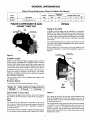
SEARS
OWNER'S
MANUAL
MODEL NO.
390.2508
CRAFTSMAN°
CAUTION:
Read andFollow
All Safety Rulesand
Operating Instructions
Before FirstUse of
This Product.
Save ThisManual For
Future Reference.
HYDROGLASS ®
SHALLOW WELL
JET PUMP
• Safety Instructions
• Installation
• Operation
• Troubleshooting
• Repair Parts
Sears, Roebuck and Co., Hoffman Estates, IL 60179
PRINTED
IN
USA.
U.S.A.
Form No
F642-04072
(Rev
2/15/05)
CONTENTS
WaL'ranty
Pump
INTRODUCTION
..............................................................................
2
Performance
..............................................................
3
Major Components
..............................................................
3
Piping ................................................................................
Installation
Electrical
4
..............................................................................
5
Operation/Maintenance
Helpful
...................................................
Guide
waiTanty.
6-9
Hints .......................................................................
Troubleshooting
Repair
3-4
...........................................................................
Please read our instructions
before installing and using your
pump. This will help you obtain the full benefits of the quality and convenience
binh into this equipment.
It will also
help you avoid any needless service expense
resulting from
causes beyond
our control which are not covered by our
9
.....................................................
Parts ........................................................................
10
11
RULES FOR SAFE INSTALLATION
1. Read
the Owners
Manual
and Rules for Installation
and
8.
Complete
pump and piping system MUST be protected
against below freezing temperature.
Allov_mg the pump
or piping to freeze could cause severe damage and voids
the Warranty.
9.
BE SURE the llne voltage and frequency
of the electrical
current supply agree with the motor wiring as shown on
motor nameplate.
Safe Operation
carefully. Failure to follow these Rules and
Instructions
could cause serious
bodily injury, and/or
property
damage.
2.
Check your
tion. ffyour
not work to
hazard, ff in
local electrical
wiring codes before installalocal codes are not followed, your pump will
its full rated capacity and could present a fire
doubt, contact your local power company.
3. BE SURE your pump installation
ing, pump and well codes.
meets
all local plumb-
4. While installing your pump, always keep the well covered
to prevent leaves and foreign matter from falling into the
well, contaminating
the water and/or causing possible serious damage to the mechanical
operation
of the pump.
5. Always test the water from well for purity before using.
Check with local health department
for testing procedure.
6.
Before installing or servicing your pump,
power source is disconnected.
7.
BE SURE
grounded.
your
pump
electrical
BE SURE pump
circuit
is properly
AND OPERATION
10. The correct fusing and vdring sizing is essential to proper
motor operation. Recommended
fusing and wire size data
is in the manual (Page 5).
11. Pump water
12. Periodically
only with this pump.
inspect
pump
and system
components.
IA CAUTION 1Motor normally operates
at high temperature
and wilt be too hot to touch. It is protected
from heat damage during operation
by an automatic
internal cutoff switch.
Before handling
pump or motor, stop
motor and allow it to cool for 20 minutes.
GENERAL
INFORMATION
Table h Pump Performance
Pump
Chart (In Gallons Per Minute)
Suction
Discharge
Discharge
Pressure
Pumping Depth in Feet
Model
Description
Size
Size
P.S.I.
5'
10'
15'
20'
390.2508
1/2 HP Standard S.W. Jet
1-1/4"
3/4"
40
7.3
6.2
5.2
4.2
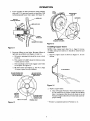
PIPING
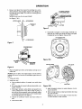
MAJOR COMPONENTS
AND
WHAT THEY DO
Piping
Relief
Valve
A Shallow well jet pump can be installed
on a dug well,
drilled well or with a driven point. In a dug or ased well, a
foot valve and strainer should be installed for easy priming.
It should be five to ten feet below the lowest level to which
the water will drop while pump is operating
(pumping
water level).
ie Tee
and Priming Plug
Water System
in the Well
Built-in
Check
Valve
The strainer should not be too close to the bottom or sediment may clog it. Before installing the foot valve, check to
see that it works freely.
When installed
on a driven pont well, your Shallow Well
Jet Pump should have a check valve installed as shown in
Figure 2.
23140E96
To Household
Figure
Impeller
Discharge
Water System
I
f-
II _--Relief
and Jet
Impeller turns with motor shaft, causing the water to fly out
from its rim by centrifugal force. Impeller rotation creates a
vacuum which puUs in more water. Part of the water is diverted back to the jet where it passes through the nozzle and
venturi. This creates more vacuum to draw in more water.
Tee
and Priming Plug
Valve
Drive
Point
In shallow wells (less than 20 feet deep), the vacuum created at the pump is enough
to pull water to the pump.
Therefore,
for shallow well use the jet is built into the pump.
Air Volume Control
The air volume control (AVC) maintains the cushion
in Standard tanks.
Pressure
The pressure
of air
Switch
switch
MODEL NO.
390.2508
provides
automatic
Couplin9
control.
This pump is equipped
with a built-in check valve. Install a
foot valve in the well on dug or cased wells. See Figure 3,
Page 4.
Tank
The tank serves two functions.
It provides
a reservoir
of
water, some of which can be drawn through the house fixture before the pump must start. It maintains
a cushion of
air under pressure.
Two types of tanks are available:
No air vohtme control is needed
Captive Air® and Standard.
with Captive® Air Tanks.
Orive
to
Point
Scale
PUMP STARTS AT [PUMP STOPS AT
_
/
_
Check Valve or Foot Valve
Not
Figure 2
For a pump at sea level, be sure the vertical distance (lift)
from the pumping water level to the pump is not over 20
feet if the pump is over the well. This wll be less if the pump
is offset from the well.
The maximum
lift of any pump decreases at the rate of about
1' less lifx for every 1,000 feet elevation above sea level. For
example,
if your are at 5,000 feet elevation
such as in
Denver, Colorado, you would loose five feet of llfx. The maximum depth from which oyou could pump water would
therefore
be 15 feet.
PIPING
Cased
Well
INSTALLATION
ff horizontal
suction pipe is more than 25' long,
priming plug at well head to allow filling of pipe.
Open
Water
SEARS jet pumps should be used vdth
(see Figure 2, Page 3). For mounting
chase tank fittings Kit No. 2788.
install
a
Captive Air® Tanks
pump to tank, pur-
SEARS Captive Air* Tanks are pre-charged
with air at the factory. Check the tank Owner's
Manual to find if air charge
needs
adjustment.
Pump
model
390.2508
requires
30
pounds for proper operation.
The Jet pump can also be mounted
on standard
tanks. A mounting
kit with an AVC is furnished
(Figure 1, Page 3). Instruction are also included.
The installation,
operation
and care of your Hydroglass®
pump is very similar to cast iron pumps. We ask, however,
that you keep the following points in mind.
Foot
Valve
IMPORTANT:
for making
self. Do not
Strainer
Screen
18360695
Figure 3
Horizontal
Piping
From
well
To Pump
When the pump is offset more than 25 feet from the well,
horizontal
piping should be increased
in size to reduce friction losses. In no case should the offset piping be smaller
than the suction tapping
of the pump.
Horizontal
t
Offset
Piping
Up 1-1/4"
to 25 Ft.
Discharge
horizontal
with tank
Sizes
for Shallow
Well Jets
1-1/2"
2 _
25 to 50 Ft.
50 to 200 Ft.
Pipe Sizes
When the pump is set at a distance from the house or point
of water use, the discharge
pipe size should be increased to
reduce pressure
losses caused by friction.
1"
l
1-1/4"
Up to 25 Ft.
_
25 to 100 Ft.
1-1/2"
100 to 600 Ft.
Use teflon tape supplied
all threaded
connections
use pipe joint compounds
with the pump
to the pump
iton the pump!
1. Wrap one and one-half to two layers of Teflon tape on all
male threads being attached
to pump. This vdll insure
leakproof
connections.
Do not overtighten
threaded fiv
tings in the plastic pump. If leaks do occur, remove the
fitting, clean
off the old Teflon tape, rewrap with one
and one-half to two Myers of new tape and remake the
connection.
2.
Be sure to support
Well Jet Pump.
3. To connect
all piping
connected
to your
Shallow
AVC to the pump, remove the 1/8" pipe plug
(Key No. 13, Page 11) from the jet portion of the pump
body near the suction tapping. Insert a 1/8" fitting into
this tapping.
Cut tubing to length and assemble the two
fittings on the air volume control and pump body.
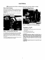
ELECTRICAL
Disconnect
Motor
Switch
power
before
working
Settings
on pump,
motor,
pressure
switch,
or wiring.
Dial Type Voltage Selector
If the motor can operate at either 115 or 230 volts, it is set
at the factory to 230 volts. Do not change motor voltage
setting if line voltage is 230 volts, or if you have a single
voltage motor.
NOTICE:
Remove
Never
wire a 115 volt motor
Hotor
to a 230 volt line.
End Cover
Figure 5 - Voltage Set To 230 Volts, Dial Type
To change to I 15 volts:
1. Make sure power
is off.
2. Turn the dial counter-clockwise
dial window.
Figure 4 - Removing
Motor
End Cover
3. Reinstall
the Motor
4. Go to Wiring
You will need to remove the motor end cover to change
the voltage setting. The illustration
above also shows the
pressure
switch. If the power supply connection
still
needs to be made, the pressure
svdtch cover v/ill need to
be removed.
Your motor terminal board (located under the motor end
cover) should look like the one at right.
Explosion
115 shows
in the
end cover
Connections,
I_,WARNING] Hazardous
kill. Connect
ground
supply
wires.
Use the
wire) specified
in the
the pump to a separate
ances on it.
[_.WARNING]
supply
line.
until
Page 6.
voltage.
Can shock,
burn, or
wire before
connecting
power
wire size (including
the ground
wiring
chart.
If possible, connect
branch circuit with no other appli-
hazard.
Do not ground
to a gas
ELECTRICAL
WIRING
CONNECTIONS
,AWARNING] Fire
hazard.
Connection
Incorrect
voltage
can cause
1.
a
fire or seriously damage the motor and voids the warranty.
The supply voltage must be within + 10% of the motor nameplate voltage.
Procedure:
Connect the ground wire first as shown in Figure 6. The
ground wire must be a solid copper wire at least as large
as the power supply wires.
2. There must be a solid metal
sure switch and the motor
tion. If the pressure switch
connect
the green ground
green ground screw under
solid copper wire at least
wires.
NOTICE:
Dual-voltage
motors are factory wired for 230
volts. If necessary,
reconnect
the motor for 115 volts, as
shown. Do not alter the wiring in single voltage motors.
Install, ground,
wire, and maintain
your pump in compliance with 'the National
Electrical
Code (NEC) or the
Canadian Electrical Code (CEC), as applicable,
and with all
local codes and ordinances
that apply. Consult your local
building inspector
for code information.
.
Motor wires connect here.
-Power supply wires connect here.
230 Volt: Connect 2 hot wires (black and red)
here and cap the white (neutral) wire. It does
not matter which wire goes to which screw
115 Volt: Connect one hot wire (black or red)
to one of these screws (it'doesn'tmatter
which one). Connect the white (neutral) wire
to the other screw. Cap any remaining
black or red wires,
4.
Connect
panel, to
casing at
provided
connection
between the presfor motor grounding
protecis not connected
to the motor,
screw in the switch to the
the motor end cover. Use a
as large as the power supply
the ground wire to a grounded
lead in a service
a metal underground
water pipe, to a metal well
least ten feet (3M) long, or to a ground electrode
by the power company or the hydro authority.
Connect the power supply
as shown in Figure 6.
5. Reinstall
the pressure
switch
wires
to the pressure
cover.
prevent strain
on the terminal
screws.
green (or bare copper) ground wire
to the green ground screw.
31870398
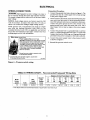
Figure 6 - Pressure switch wiring
TABLE
Ih WIRING
CHART
-
Recommended
Fusing and Wiring
Data
Distance in Feet From Motor to Meter
Motor
Horsepower
Volts
Max.
Load
Amperes
1/2
115/230
10.4/5.2
Branch*
Fuse
Rating
Amps
0'
to
50'
15/15
14/14
51'
to
100'
r 14/14
101'
201'
to
to
200'
300'
Wire Size
{
• Time delayed fuses are recommended instead of regular fuses in any motor circuit.
6
201'
to
400'
401'
to
500'
10/14! 8/t416/1416/12
switch
OPERATION
Disassembly and Assembly of Pump
Priming the Pump
NOTE: To properly prime the pump, install a pipe tee in the
discharge piping, similar to that shown in Figures 1 and 2 on
Page 3.
[& CAUTION Never run pump
dry. Running pump without water may cause pump to overheat,
damaging seal and possibly causing burns to persons handling
pump. Fill pump with water before starting.
&WARNING
tempting
Your SEARS pump is designed
for ease in servicing. Should
repair or replacement
of the motor or seal be needed,
the
pump and piping do not need to be disconnected
or disturbed.
l.
_WARNING
Explosion
Hazard.
Never run pump against
closed discharge.
To do so can boil water inside pump, causing hazardous
pressure
ha unit, risk of explosion and possibly scalding persons handling
pump.
To prevent
motor
until
To prime
1.
damage
to internal
parts,
pump has been filled with
priming
plug (Figure
2.
several
times, no water
A. Be sure suction
pipe
is in the water.
B. Be sure suction
pipe
has no leaks.
C. Be sure the pump is not trying to lift water
(See "Piping in the Well," Page 4).
6.
MAINTAINING
YOUR
D. Replace
too high.
PUMP
body
and
of pump:
on seal plate (Key Nos. 5 and 3,
C. Replace motor onto pump body; be sure rubber pad
(Key No. 8, Page 12) stays in place on top of diffuser.
Remount base on lower studs. Tighten four hexnuts
and lockwashers
snugly (35_15 inch-lbs, torque). Do
not overtighten.
is pumped,
As long as foot valve and check valve function
correctly
and suction pipe does not develop leaks, pump should
not need repriming
in normal service.
from pump
B. Pick up a small amount of petroleum
jelly on one finger and spread evenly over seal plate and venturi
O-Ring gasket for lubrication during reassembly.
Be
careful not to nick or tear O-Ring.
From ten to 20 foot depths, it is very likely you v_ill have
to shut the pump off and reptime
per the outlined procedure several times.
If, after priming pump
check the following:
Reassembly
A. install O-Ring gasket
Page 12).
On shallow depths to water (ten feet or less), the pump
vdIl more than likely prime the first time after following
the outlined procedure.
5.
tube
D. Remove motor, seal plate, impeller,
rubber pad and
diffuser (Key Nos. 1, 3, 7, 8 and 9, Page 12) as a unit.
You may have to pry gently with two screwdrivers
between the motor flange and the pump body to separate pump and motor.
plug, using Teflon tape on plug threads;
in 1-2 minutes.
as follows:
power.
C. Remove four hexnuts and lockwashers
(Key Nos. 24
and 23, Page 12) which hold the pump body to the
motor.
start
1, Page 3).
Start the pump. Water should be pumped
If not, repeat steps 1, 2 and 3.
ptmap
B. Remove pressure switch
allow pump to drain.
with water.
3. Replace priming
tighten plug.
Disassemble
A. Disconnect
pump:
Remove
2. Fill pump
4.
do not
water.
Risk of electrical
shock.
Be sure Unit is
grounded
and power disconnected
before atany work on pump or motor.
pressure
switch
E. Prime pump according
F. Check for leaks.
Removing
Motor
tubing
and motor
to instructions
wiring.
above.
for Service
and Replacing Shaft Seal
Lubrication
If it is necessary to separate motor and seal plate,
place the shaft seal. We suggest you purchase
U109_A, and have it on hand for future use.
It is not necessary
to lubricate
the pump or its motor. The
motor bearings are lubricated
for life. The mechanical
shaft
seal in the pump is water lubricated
and self-adjusting.
NOTICE: The seal consists of two parts, a rotating member
and a ceramic seat. The surfaces of the seal are easily damaged. Read instructions
carefully.
Remove
Draining
for Winter
When the pump is to be disconnected
from service or is in
danger of freezing, it must be drained.
To drain it, turn off
power and relieve all pressure
on the system. Remove pressure switch
tubing from the side of the pump housing.
Remove the priming plug to vent the pump. Drain the pressure tank; drain all piping to a point below the freeze line.
To drain an air volume
control
(AVC), remove
the tubing
from it and turn the AVC upside down. This will permit any
water in the AVC to drain into tank.
motor
as follows:
l.
Disassemble
2.
Remove diffuser
7, Page 12).
A. Remove
always rethis item,
pump
per instructions
and impeller
screws
holding
as follows
D. Turn impeller
(Key Nos. 9 and
diffuser.
B. Loosen two screws aiad remove
motor (Key No. 1, Page 12).
C. Place 7/16" open
above.
end wrench
counterclockwise
motor
on motor
when
canopy
from
shaft flat.
facing
it.
OPERATION
3. Remove seal plate from motor by inserting
two screwdrivers between
the seal plate and the motor flange. Pry
seal plate off motor flange. This will force rotating portion
of seal off shaft.
CARDBOARDWASHER
NOTE:
Be sure you do not scratch
shaft!
See Figures 7 & 8.
MOTOR FLANGE
SCREWDRIVER
D WITHSEAL
HALF
CUP/St .=L_
PUMPBACK
Figure
MOTOR
3/4" PIPE
9
F. Reassemble
seal plate to motor flange. BE SURE it is
right side up: index pins should be down; seal plate
is marked at top. See Figures 10A and lOB.
_CREWDRIVER
TOP OF MOTOR FLANGE
Figure 7
COPPER SEAT
SEAL
Figure
PLATE INDEX PINS
SLIDE IN HERE
I OA
FLOATING
SEAT
MEMBER
MOTOR
FLANGE
SEAL PLATE
Figure 8
4.
Place sea! plate face down
ram,ic seat.
on flat surface
NOTICE: Do not force out copper
insert.
leakage will occur. See section on installing
Page 9.
5. Clean
6.
and tap out ceIf it has moved,
copper insert on
seal cavity.
Install new seal.
A. Clean polished
cloth.
surface
of ceramic
seat with clean
INDEX PINS
B. Wet outer edge of cup seal with petroleum
tergent solution.
jeUy or de-
C. With finger pressure,
press firmly and squarely into
cavity. Polished face of seat faces inside of pump. If
seat will not locate properly, place cardboard
washer
over polished face and use piece of 3/4" standard pipe
for pressing purposes.
See Figure 9.
D. Dispose
seat.
of cardboard
E. Clean motor
shaft.
washer
and clean
surface
of
Figure
I OB
G. Apply detergent
ing seal member.
solution
H. Slide rotating member
hits shaft shoulder.
to inside diameter
on shaft until rubber
NOTE: Be sure you do not chip or scratch
on shaft shoulder
or seal will leak!
of rotatdrive ring
seal face
OPERATION
I.
Screw impeller
on shaft (clockwise)
while holding
shaft wzth 7/16" open end wrench on shaft flats. This
v_fll automatically
locate seal in place. See Figure 11.
SEAL
PLATE
HOLES MUST
LINE UP
DIFFUSER
FACE OF
SEALING WASHER
IMPELLER
HUB
SHAFT
SHOULDER
%
BE SURE NIBS
ENGAGE NOTCHES
RUBBER
DRIVE RING
Figure 13
Figure
Installing
II
Remount
diffuser on seal plate. Be sure diffuser
right side up as follows (see Figures 13 and 14).
a.
Rib next
position;
b.
Part number
(N1-28P) should
o'clock and ten o'clock.
c.
Both mounting
screws must engage
in seal plate. See Figure 12.
d.
Be sure rubber pad (Figure 12; Key No. 8, Page
12) stays in place on top of diffuser.
BE SURE RUBBER
STAYS IN PLACE
to priming
PAD
ON
hole should
is
be at six o'clock
be between
Insert
NOTE: If the copper
insert (Key No. 4, Page 12) moves
or shifts during seal removal,
it should be removed
and
reinstalled.
1. Remove
deform.
copper
insert
as shown
in Figure
14. do not
nine
screw
BESURESCREW
ENGAGES HOLE
SEALPLATE
Copper
holes
TO DISASSEMBLE
IN
Figure
14
2. Replace copper insert:
MOLDED
PART NO.
AT 9:30
O'CLOCK
RIB AT E O'CLOCK
Figure
12
BE SURE SCREW
ENGAGES HOLE
IN SEAL PLATE
PRIMING
A. Clean off surplus Permatex* from around insert cavity. Be careful not to scratch or mark the machined
bore. It is important that this area be clean no no old
Permatex lodges behind the new insert and causes improper seating.
HOLE
* "Permatex"
is a registered trademark of Permatex Co. Inc.
OPERATION
B. Place a small amount
of No. 2 non-hardening
Permatex
on surface of insert as shown. Smooth out
with finger. See Figure 15.
Cleaning
To remove
Shallow
debris from venturi
1. Disassemble
Wipe on small amount of
non-hardening Permatex
on this surface
Figure
15
C. Pull insert
into cavity as shown
in Figure 16.
Well
pump
Jet
or nozzle,
per instructions
proceed
as follows:
on Page 7.
2.
Turn venturi counterclockwise
and remove it. The nozzle is now exposed.
Remove it using a 5/8" hex socket
wrench with extension.
Turn counterclockwise.
If socket
wrench
is not available,
insert an ice pick or similar
pointed tool carefully into the nozzle. This will dislodge
debris.
3.
Flush out the debris by running water through the nozzle
in the same direction as the dislodging tool was inserted.
4.
Replace
5.
Reassemble
nozzle
and venturi.
per pump
Do not overtighten!
instructions
HELPFUL
How
to Handle
on Page 7.
HINTS
a Gaseous
Well
In some areas well water contains gases which must be atlowed to escape before the water is used. This can be done
as shown in Figure 18.
Socket
Gases
rise to
$u_ace
Figure
16
D. Clean
where
wimtohold
pipe slBeve
out any surplus Permatex
from insert cavity
new seal will be located. See Figure 17.
Remove
/_
Not
pUr=U'
to
pipe
valvo
Scale
cap
ProperlyJ
Figure
Seated
Figure
"
Impeller
1. Follow steps 1A through 1D under
Assembly
of Pump" on Page 7.
2.
A good way of delivering gas-free water is to suspend a pipe,
closed at the bottom
and open at the top, surrounding
the
suction
pipe. Since the gases rise in the well casing, the
water sucked down through
the pipe and into the suction
pipe is free of gas. This type of well must be vented to the
outside of any enclosure.
I7
Cleaning
18
"Disassembly
and
Air Control
Remove diffuser and impeller from pump per instructions
under "Removing Motor for Service and Replacing Shaft
Seal" on Page 7.
3. Clean impeller and reassemble
impeller
instructions
under
"Removing
Motor
Replacing Shaft Seal" on Page 7.
and diffuser
for Serivce
in Flowing
Wells
Flowing wells, or wells with little or no drawdown,
could
create a special problem
in air control in the operation
of
your water system.
per
and
In such cases, install
any air control.
10
a Captive
Air* Tank. It does not require
TROUBLESHOOTING
SYMPTOM
POSSIBLE CAUSE(S)
Motor will not run
switch
CHART
CORRECTIVE ACTION
1.
Disconnect
2.
Fuse is blown
is off
1. Be sure switch
3.
Starting switch
4.
Wires at motor are loose,
disconnected,
or wired incorrectly
4. Refer to instructions
5.
Pressure
5. Cleanbyslidingpiecesofplainpaperbctweencontacts
2. Replace
is defective
switch
contacts
is on
false
3. Replace sta_ing
are dirty
on wiring.
Motor runs hot and
1. Motor is wired
2.
Voltage is too low
2. Check with power company. Install heavier
size is too small. See wiring instructions
3.
Pump
3. See section
I.
Pump in new installation did
not pick up prime through:
a, Improper prinling
b. Air leaks
Motor runs but no
water is delivered
c.
2.
1. Refer to instructions
Check and tighten
overload
kicks off
incorrectly
switch
cycles too frequently
Leaking
below on too frequent
of pump
4.
Check valve or foot valve is stuck
in cinsed position
is plugged
4. Replace
5.
Pipes are frozen
5. Thaw pipes.
6.
Foot valve and/or strainer
buried in sand or mud
Pump does not
deliver water to full
1.
Water level in well is lower
estimated
capacity (Also
check point 3
2.
Steel piping (if used) is corroded
limed, causing excess friction
3,
Offset piping
I,
Pressure switch is out of adjustment
or contacts are "frozen"
1. Adjust or replace
2.
Faucets
2. Close faucets
Pump cycles too
frequently
3
are
check
control,
according
1. A deep weIl jet pump
or
have been left open
is clogged
•
Bury pipes below frost line. Heat pit or pump
6. Raise foot valve and/or
than
to instructions
valve or foot valve
strainer
above
may be needed
2. Replace with plastic pipe where
house.
well bottom
(over 20 ft. to water)
possible,
otherwise
with new steel pipe
3. Use larger offset piping
pressure
switch
3. Clean jet or impeller
4.
Water level in well is lower than
estimated
4. Check possibility
5.
Motor is wired
5. Refer to instructions
1.
Standard pressure tank is waterlogged and has no air cushion
1. Drain tank to air volume control tapping. Check
defects. Check for air leaks at any connection
2.
Pipe leak
2. Check
Faucets
3. Close faucets
3.
Air spurts from
faucets
3, Clean jet or impeller
is too small in size
3. Jet or impeller
line, air volume
and jet
jet and shaft seal
b. Lower suction line intu water and re-prime. If recedirtg water level
in well exceeds suction lift, a deep well pump is needed
Jet or impeller
Pump pumps water
but does not shut
off
cycling
2. In installation already in use:
a. Check all connections
on suction
through:
3.
above)
wiring if wire
a. Re-prime according to instructions
b. Check all connections
on suction line, air volume control,
c. Replace foot valve
b. Water level below suction
immediately
on wiring
1, In new instalJation:
foot valve
Pump has lost prime
a. Air leaks
all wiring.
incorrectly
or valves are open
of using a deep well jet pump
on wiring
air volume
control
for
connections
or valves
4.
Foot valve leaks
5.
Pressure
6.
Air charge too low in
Captive Air* Tank
6. Disconnect
electrical power and open faucets until all pressure is
relieved. Using automobile tire pressure gauge, check air pressure in tank
at the valve stem located at top of tank. If air pressure is lower, pump air
into tank from outside source undi proper air pressure is reached. Check
air valve for leaks, oKmg soapy solution, and replace core If necessary.
1.
Pump is picking
1. As soon as pump
switch
o2.
Leak in suction
3.
Well is gaseous
4.
lr_termlttent
is out of adjustment
up prime
side of pump
over-pumping
4. Replace
foot valve
5. Replace
pressure
2. Check
suction
4.
picks up prime,
as described
Lower foot valve if possible,
11
all air will be ejected
piping
3. Change installation
of well
switch
in manual
otherwise
restrict
discharge
side of pump
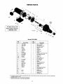
REPAIR
PARTS
1
28
2
4
6
7 8
9
10
26
11
25
24
23
AVC
Port
22
21
20
To Order
Parts,
Sears Product
Call
18
17
Service,
1-800-366-7278
2305 0296
J
14
Model
Key
No,
Part Number
13
J
12A
/
12B
390.2508
Qty.
Used
Description
1#
2
3*
4
J218-g53c
17351-0009
N203-12P
J3-2
1
1
1
1
Motor - 115/230V
Water Slinger
Sea_ Plate Assembly
Seal Plate Insert
5
6
7
8
9
U9-390
U 109-6A
J105-40PF
C35-41
N 1-28P
1
1
1
1
1
O-Ring
Shaft Seal
Impeller
Rubber Pad
Diffuser
10
11**
12
12A
12B
U30-738SS
N 176-35PE
N76-38PE
U9-226
N166-5P
2
1
1
1
1
Capscrew #10-16 Hex Head
Pump Body Assembly
Pump Body
O-Ring
Check Valve
131"
14
15
16
17
18
19
20
U111-212T
U37-669P
J20-18
N76-29P
U30-742SS
N34P-19
N32P-66
1
2
1
1
1
4
1
1
Pipe Plug 1/8" NPT
90 ° Hose Barb
Switch Tube
Gasket
Pump Body Jet Insert
Capscrew #10-16
Nozzre #45
Venturi
1
t
4
4
1
1
1
1
O-Ring
Base Assembly Painted
Lock Washer 3/8"
Nut 3/8" - 16
Rubber Pad
Pressure switch
Locknut 1/2"
Connector 1/2"
21
22
23t
24t
25
26
271"
28
/
12
U9-201
J104-gP
C35-5
2781
L43-5C
# For repair or service to motors, always give the meter model number and any other data found on the motor model plate.
• Includes Key Nos. 4 and 5.
** Includes Key Nos. 12, 12A, 12B, and 16 through 21,
t Standard hardware item, may be purchased locally.
12
13
14
15
SEARS
OWNER'S
MANUAL
I:RRFTSMRN*
HYDROGLASS ®
SHALLOW WELL
JET PUMP
Forthe repair or replacementpartsyou need
Call 7 am - 7 prn, 7 days a week
1-800-366-PART
MODEL NO.
(1-800-366-7278)
390.2508
Forin-homemajorbrandrepair service
Call24 hours a day, 7 days a week
1-800-4-REPAIR
(1-800-478-7247)
The model number of
your Shallow Well Jet
Pumpwill be found on a
plate attached to the
pump discharge
connection.
When requesting service
or ordering parts, always
give the following
information:
• Product Type
• Model Number
• Part Number
Forthe locationof a
SearsRepairServiceCenterin yourarea
Call 24 hours a day,7 days a week
1-800-488-1222
For informationon purchasinga Sears
MaintenanceAgreementor to inquire
aboutan existingAgreement
call 9 am - 5 pm, Monday-Saturday
1-800-827-6655
SEARS
Ame#ca
's Repair
Specialists
• Part Description
Sears, Roebuck and Co., Hoffman Estates, IL 60179
U.S.A.