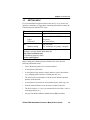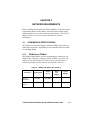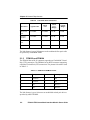
1
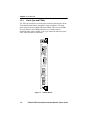
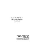
7F06-02 FDDI SmartSwitch™ Interface Module User’s Guide Title Page 903 9031672-02 Only qualified personnel should perform installation procedures. NOTICE Cabletron Systems reserves the right to make changes in specifications and other information contained in this document without prior notice. The reader should in all cases consult Cabletron Systems to determine whether any such changes have been made. The hardware, firmware, or software described in this manual is subject to change without notice. IN NO EVENT SHALL CABLETRON SYSTEMS BE LIABLE FOR ANY INCIDENTAL, INDIRECT, SPECIAL, OR CONSEQUENTIAL DAMAGES WHATSOEVER (INCLUDING BUT NOT LIMITED TO LOST PROFITS) ARISING OUT OF OR RELATED TO THIS MANUAL OR THE INFORMATION CONTAINED IN IT, EVEN IF CABLETRON SYSTEMS HAS BEEN ADVISED OF, KNOWN, OR SHOULD HAVE KNOWN, THE POSSIBILITY OF SUCH DAMAGES. Copyright 1998 by Cabletron Systems, Inc., P.O. Box 5005, Rochester, NH 03866-5005 All Rights Reserved Printed in the United States of America Order Number: 9031672-02 January 1998 Cabletron Systems, SPECTRUM, and LANVIEW are registered trademarks and SmartSTACK, ELS10-26TX, FEPIM, FEPIM-TX and FEPIM-FX are trademarks of Cabletron Systems, Inc. All other product names mentioned in this manual may be trademarks or registered trademarks of their respective companies. FCC NOTICE This device complies with Part 15 of the FCC rules. Operation is subject to the following two conditions: (1) this device may not cause harmful interference, and (2) this device must accept any interference received, including interference that may cause undesired operation. NOTE: This equipment has been tested and found to comply with the limits for a Class A digital device, pursuant to Part 15 of the FCC rules. These limits are designed to provide reasonable protection against harmful interference when the equipment is operated in a commercial environment. This equipment uses, generates, and can radiate radio frequency energy and if not installed in accordance with the operator’s manual, may cause harmful interference to radio communications. Operation of this equipment in a residential area is likely to cause interference in which case the user will be required to correct the interference at his own expense. WARNING: Changes or modifications made to this device which are not expressly approved by the party responsible for compliance could void the user’s authority to operate the equipment. Printed on Recycled Paper 7F06-02 FDDI SmartSwitch Interface Module User’s Guide i Notice DOC NOTICE This digital apparatus does not exceed the Class A limits for radio noise emissions from digital apparatus set out in the Radio Interference Regulations of the Canadian Department of Communications. Le présent appareil numérique n’émet pas de bruits radioélectriques dépassant les limites applicables aux appareils numériques de la class A prescrites dans le Règlement sur le brouillage radioélectrique édicté par le ministère des Communications du Canada. VCCI NOTICE This is a Class A product based on the standard of the Voluntary Control Council for Interference by Information Technology Equipment (VCCI). If this equipment is used in a domestic environment, radio disturbance may arise. When such trouble occurs, the user may be required to take corrective actions. CABLETRON SYSTEMS, INC. PROGRAM LICENSE AGREEMENT IMPORTANT: Before utilizing this product, carefully read this License Agreement. This document is an agreement between you, the end user, and Cabletron Systems, Inc. (“Cabletron”) that sets forth your rights and obligations with respect to the Cabletron software program (the “Program”) contained in this package. The Program may be contained in firmware, chips or other media. BY UTILIZING THE ENCLOSED PRODUCT, YOU ARE AGREEING TO BECOME BOUND BY THE TERMS OF THIS AGREEMENT, WHICH INCLUDES THE LICENSE AND THE LIMITATION OF WARRANTY AND DISCLAIMER OF LIABILITY. IF YOU DO NOT AGREE TO THE TERMS OF THIS AGREEMENT, PROMPTLY RETURN THE UNUSED PRODUCT TO THE PLACE OF PURCHASE FOR A FULL REFUND. ii 7F06-02 FDDI SmartSwitch Interface Module User’s Guide Notice CABLETRON SOFTWARE PROGRAM LICENSE 1. LICENSE. You have the right to use only the one (1) copy of the Program provided in this package subject to the terms and conditions of this License Agreement. You may not copy, reproduce or transmit any part of the Program except as permitted by the Copyright Act of the United States or as authorized in writing by Cabletron. 2. OTHER RESTRICTIONS. You may not reverse engineer, decompile, or disassemble the Program. 3. APPLICABLE LAW. This License Agreement shall be interpreted and governed under the laws and in the state and federal courts of New Hampshire. You accept the personal jurisdiction and venue of the New Hampshire courts. EXCLUSION OF WARRANTY AND DISCLAIMER OF LIABILITY 1. EXCLUSION OF WARRANTY. Except as may be specifically provided by Cabletron in writing, Cabletron makes no warranty, expressed or implied, concerning the Program (including its documentation and media). CABLETRON DISCLAIMS ALL WARRANTIES, OTHER THAN THOSE SUPPLIED TO YOU BY CABLETRON IN WRITING, EITHER EXPRESSED OR IMPLIED, INCLUDING BUT NOT LIMITED TO IMPLIED WARRANTIES OF MERCHANTABILITY AND FITNESS FOR A PARTICULAR PURPOSE, WITH RESPECT TO THE PROGRAM, THE ACCOMPANYING WRITTEN MATERIALS, AND ANY ACCOMPANYING HARDWARE. 2. NO LIABILITY FOR CONSEQUENTIAL DAMAGES. IN NO EVENT SHALL CABLETRON OR ITS SUPPLIERS BE LIABLE FOR ANY DAMAGES WHATSOEVER (INCLUDING, WITHOUT LIMITATION, DAMAGES FOR LOSS OF BUSINESS, PROFITS, BUSINESS INTERRUPTION, LOSS OF BUSINESS INFORMATION, SPECIAL, INCIDENTAL, CONSEQUENTIAL, OR RELIANCE DAMAGES, OR OTHER LOSS) ARISING OUT OF THE USE OR INABILITY TO USE THIS CABLETRON PRODUCT, EVEN IF CABLETRON HAS BEEN ADVISED OF THE POSSIBILITY OF SUCH DAMAGES. BECAUSE SOME STATES DO NOT ALLOW THE EXCLUSION OR LIMITATION OF LIABILITY FOR CONSEQUENTIAL OR INCIDENTAL DAMAGES, OR ON THE DURATION OR LIMITATION OF IMPLIED WARRANTIES, IN SOME INSTANCES THE ABOVE LIMITATIONS AND EXCLUSIONS MAY NOT APPLY TO YOU. UNITED STATES GOVERNMENT RESTRICTED RIGHTS The enclosed product (a) was developed solely at private expense; (b) contains “restricted computer software” submitted with restricted rights in accordance with Section 52227-19 (a) through (d) of the Commercial Computer Software - Restricted Rights Clause and its successors, and (c) in all respects is proprietary data belonging to Cabletron and/or its suppliers. For Department of Defense units, the product is licensed with “Restricted Rights” as defined in the DoD Supplement to the Federal Acquisition Regulations, Section 52.227-7013 (c) (1) (ii) and its successors, and use, duplication, disclosure by the Government is subject to restrictions as set forth in subparagraph (c) (1) (ii) of the Rights in Technical Data and Computer Software clause at 252.227-7013. Cabletron Systems, Inc., 35 Industrial Way, Rochester, New Hampshire 03867-0505. 7F06-02 FDDI SmartSwitch Interface Module User’s Guide iii Notice DECLARATION OF CONFORMITY Application of Council Directive(s): Manufacturer’s Name: Manufacturer’s Address: European Representative Name: European Representative Address: Conformance to Directive(s)/Product Standards: Equipment Type/Environment: 89/336/EEC 73/23/EEC Cabletron Systems, Inc. 35 Industrial Way PO Box 5005 Rochester, NH 03867 Mr. J. Solari Cabletron Systems Limited Nexus House, Newbury Business Park London Road, Newbury Berkshire RG13 2PZ, England EC Directive 89/336/EEC EC Directive 73/23/EEC EN 55022 EN 50082-1 EN 60950 Networking Equipment, for use in a Commercial or Light Industrial Environment. We the undersigned, hereby declare, under our sole responsibility, that the equipment packaged with this notice conforms to the above directives. Manufacturer Legal Representative in Europe Mr. Ronald Fotino ___________________________________ Mr. J. Solari ___________________________________ Full Name Full Name Principal Compliance Engineer ___________________________________ Title Rochester, NH, USA ___________________________________ Location iv Managing Director - E.M.E.A. ___________________________________ Title Newbury, Berkshire, England ___________________________________ Location 7F06-02 FDDI SmartSwitch Interface Module User’s Guide CONTENTS CHAPTER 1 INTRODUCTION 1.1 Using This Manual....................................................................... 1-1 1.2 The 7F06-02 Module ................................................................... 1-1 1.2.1 Cable Type and FPIMs ................................................... 1-2 1.2.2 7C03 MMAC SmartSwitch, the 7C04 Workgroup SmartSwitch and the 7C04-R Workgroup SmartSwitch.................................................................... 1-3 1.3 Features ...................................................................................... 1-3 1.3.1 FPIMs ............................................................................. 1-3 1.3.2 LANVIEW LEDs .............................................................. 1-3 1.3.3 Connectivity .................................................................... 1-4 1.4 Related Manuals.......................................................................... 1-4 1.5 Getting Help................................................................................. 1-5 CHAPTER 2 NETWORK REQUIREMENTS 2.1 FPIM Module Specifications ........................................................ 2-1 2.1.1 FPIM-00 and FPIM-01 .................................................... 2-1 2.1.2 FPIM-02 and FPIM-04 .................................................... 2-2 2.1.3 FPIM-05 and FPIM-07 .................................................... 2-3 CHAPTER 3 INSTALLATION/REMOVAL 3.1 Unpacking The 7F06-02 Module ................................................. 3-1 3.2 Installing FPIMs ........................................................................... 3-2 3.3 Installing/Removing The 7F06-02 Module................................... 3-3 3.3.1 Installing in the 7C03 SmartSwitch ................................. 3-3 3.3.2 Removing from the 7C03 SmartSwitch........................... 3-4 3.3.3 Installing in the 7C04 or 7C04-R Workgroup SmartSwitch ................................................. 3-5 3.3.4 Removing the 7F06-02 from the 7C04 or 7C04-R Workgroup SmartSwitch ............................... 3-8 CHAPTER 4 TROUBLESHOOTING 4.1 Diagnostic and Monitoring System .............................................. 4-1 4.2 Port Receive LEDs ...................................................................... 4-2 4.3 Port Transmit LEDs ..................................................................... 4-2 4.4 A/B Link LEDs ............................................................................. 4-2 7F06-02 FDDI SmartSwitch Interface Module User’s Guide v Contents CHAPTER 5 TECHNICAL SPECIFICATIONS 5.1 Standards.....................................................................................5-1 5.2 EMI...............................................................................................5-1 5.3 EMC .............................................................................................5-1 5.4 Network Interfaces .......................................................................5-1 5.5 Safety...........................................................................................5-2 5.6 Service .........................................................................................5-2 5.7 Physical........................................................................................5-2 5.7.1 Dimensions......................................................................5-2 5.7.2 Weight .............................................................................5-2 vi 7F06-02 FDDI SmartSwitch Interface Module User’s Guide CHAPTER 1 INTRODUCTION Welcome to Cabletron Systems 7F06-02 FDDI SmartSwitch Interface Module User Guide. This guide is a simple reference for installing and using the 7F06-02 Module. Before installing this module, you should carefully read through this manual to gain a full understanding of its capabilities. The 7F06-02 Module is a two-port FDDI module. This module connects to a network and the 7X00 SmartSwitch™ Control Module in the 7C03, 7C04 or 7C04-R MMAC SmartSwitch via a SmartSwitch bus. 1.1 USING THIS MANUAL Chapter 1, Introduction, discusses the capabilities and special features of Cabletron Systems 7F06-02 Module. This chapter also includes a list of related manuals. Chapter 2, Network Requirements, contains a list of available FPIMs and the network requirements that should be considered before installing the 7F06-02 Module. Chapter 3, Installation/Removal, contains instructions for installing and removing the 7F06-02 in the 7C03 MMAC SmartSwitch, the 7C04 Workgroup SmartSwitch or the 7C04-R Workgroup SmartSwitch. Chapter 4, Troubleshooting, contains instructions for using LANVIEW® (Cabletron Systems built-in diagnostic and status monitoring system). Chapter 5, Technical Specifications, provides detailed information about the physical characteristics of the 7F06-02 Module. 1.2 THE 7F06-02 MODULE The 7F06-02 Module, shown in Figure 1-1, provides two fiber optic ports via front panel FPIM modules. 7F06-02 FDDI SmartSwitch Interface Module User’s Guide 1-1 Chapter 1: Introduction 1.2.1 Cable Type and FPIMs The 7F06-02 module has two front panel connectors that interface to the 7X00 SmartSwitch Module through the chassis backplane. The front panel connections are standard Cabletron FPIMs. There are two FPIMs for each channel. These FPIMs allow the use of single mode or multimode fiber cable with MIC or SC type connectors and twisted pair cable, either shielded or unshielded. 7F06-02 SP A F D D I 1 SN P S A B B A F D D I 2 P S A B B Figure 1-1 1-2 7F06-02 Module 7F06-02 FDDI SmartSwitch Interface Module User’s Guide Chapter 1: Introduction 1.2.2 7C03 MMAC SmartSwitch, the 7C04 Workgroup SmartSwitch and the 7C04-R Workgroup SmartSwitch The 7F06-02 Module is designed to be installed in the 7C03 MMAC SmartSwitch, the 7C04 Workgroup SmartSwitch or the 7C04-R Workgroup SmartSwitch. The modular design of the 7C03 MMAC SmartSwitch allows other modules that support Ethernet, Fast Ethernet, ATM, FDDI, or Token Ring to be used with the 7F06-02 Module. These modules provide the capability to share data without the use of external bridges or routers. The 7C03 MMAC SmartSwitch is a unique module that can be installed in an MMAC Series chassis. The 7C04 Workgroup SmartSwitch and the 7C04-R Workgroup SmartSwitch are stand-alone chassis that provide the same functions. 1.3 FEATURES The 7F06-02 Module provides two FDDI ports via front panel FPIMs. The 7F06-02 Module includes the following features: 1.3.1 FPIMs The front panel connections are standard Cabletron FPIMs. These FPIMs allow the use of single mode or multimode fiber cable with MIC or SC type connectors. 1.3.2 LANVIEW LEDs The 7F06-02 uses LANVIEW, Cabletron Systems built-in visual diagnostic and status monitoring system. With LANVIEW LEDs, you can quickly identify, at a glance, the status of the device connected to a port on the 7F06-02 Module. 7F06-02 FDDI SmartSwitch Interface Module User’s Guide 1-3 Chapter 1: Introduction 1.3.3 Connectivity The 7F06-02 Module has one backplane connection and two sets of A/B front panel FPIM connections. The backplane connection provides power to the 7F06-02 Module and a channel for communication with the 7X00 SmartSwitch Control Module. The two front panel FPIMs provide FDDI connections, allowing the use of single mode or multimode fiber cable with MIC or SC type connectors. 1.4 RELATED MANUALS The following Cabletron Systems manuals supplement the procedures and other technical data provided in this manual. The procedures will be referenced, where appropriate, but will not be repeated. 7X00 SmartSwitch Control Module User’s Guide 7F06-02 Local Management Appendix 7C03 MMAC SmartSwitch Installation Guide 7C04 Workgroup SmartSwitch Installation Guide 7C04-R Workgroup SmartSwitch Installation Guide 1-4 7F06-02 FDDI SmartSwitch Interface Module User’s Guide Chapter 1: Introduction 1.5 GETTING HELP If you need additional support related to this device, or if you have any questions, comments, or suggestions concerning this manual, contact the Cabletron Systems Global Call Center: Phone (603) 332-9400 Internet mail [email protected] FTP ctron.com (134.141.197.25) Login anonymous Password your email address BBS (603) 335-3358 Modem setting 8N1: 8 data bits, No parity, 1 stop bit For additional information about Cabletron Systems or our products, visit our World Wide Web site: http://www.cabletron.com/ For technical support, select: Service and Support. Before calling the Cabletron Systems Global Call Center, have the following information ready: • Your Cabletron Systems service contract number • A description of the failure • A description of any action(s) already taken to resolve the problem (e.g., changing mode switches, rebooting the unit, etc.) • The serial and revision numbers of all involved Cabletron Systems products in the network • A description of your network environment (layout, cable type, etc.) • Network load and frame size at the time of trouble (if known) • The device history (i.e., have you returned the device before, is this a recurring problem, etc.) • Any previous Return Material Authorization (RMA) numbers 7F06-02 FDDI SmartSwitch Interface Module User’s Guide 1-5 Chapter 1: Introduction 1-6 7F06-02 FDDI SmartSwitch Interface Module User’s Guide CHAPTER 2 NETWORK REQUIREMENTS Before installing Cabletron Systems 7F06-02 Module, review the network requirements outlined in this chapter. All requirements included in this chapter should be met to ensure satisfactory performance of the 7F06-02 Module. Failure to do so may result in unsatisfactory network performance. 2.1 FPIM MODULE SPECIFICATIONS This module uses Fiber Port Interface Modules (FPIM) to provide front panel cable connections. The FPIMs are user-installable. Refer to Section 3.2, Installing FPIMs. 2.1.1 FPIM-00 and FPIM-01 The FPIM-00 and FPIM-01 provide a multimode fiber connection. The FPIM-00 uses a MIC style connector and the FPIM-01 uses an SC type connector. The specifications for both devices are listed in Table 2-1, while the transmitter power parameters are provided in Table 2-2. Table 2-1 Parameter FPIM-00 and FPIM-01 Specifications Typical Value Worst Case Worst Case Budget Typical Budget Receive Sensitivity -30.5 dBm -28.0 dBm — — Peak Input Power -7.6 dBm -8.2 dBm — — 7F06-02 FDDI SmartSwitch Interface Module User’s Guide 2-1 Chapter 2: Network Requirements Table 2-2 Parameter Transmitter Power Parameters Typical Value Worst Case Worst Case Budget Typical Budget 50/125 µm fiber -13.0 dBm -15.0 dBm 13.0 dB 17.5 dB 62.5/125 µm fiber -10.0 dBm -12.0 dBm 16.0 dB 20.5 dB 100/140 µm fiber -7.0 dBm -9.0 dBm 19.0 dB 23.5 dB Error Rate Better than 10-10 The link distance is up to 2 kilometers on the multimode fiber optic cable as specified by ANSI MMF-PMD. 2.1.2 FPIM-02 and FPIM-04 The FPIM-02 has an RJ-45 connector supporting an Unshielded Twisted Pair (UTP) connection. The FPIM-04 has an RJ-45 connector supporting a Shielded Twisted Pair (STP) connection. The pinouts for both are listed in Table 2-3. Table 2-3 Pin Number FPIM-02 and FPIM-04 Pinouts Represents Pin Number Represents 1 Transmit+ 5 NA 2 Transmit- 6 NA 3 NA 7 Receive+ 4 NA 8 Receive- The link distance is up to 100 meters on unshielded twisted pair cable as specified by ANSI TP-PMD. 2-2 7F06-02 FDDI SmartSwitch Interface Module User’s Guide Chapter 2: Network Requirements 2.1.3 FPIM-05 and FPIM-07 The FPIM-05 and FPIM-07 provide a single-mode fiber connection. The FPIM-05 uses a MIC style connector and the FPIM-07 uses an SC type connector. The specifications for both devices are listed in Table 2-4. Table 2-4 FPIM-05 and FPIM-07 Specifications Parameter Typical Minimum Maximum Transmitter Peak Wave Length 1300 nm 1270 nm 1330 nm Spectral Width 60 nm - 100 nm Rise Time 3.0 nsec 2.7 nsec 5.0 nsec Fall Time 2.5 nsec 2.2 nsec 5.0 nsec Duty Cycle 50.1% 49.6% 50.7% Bit Error Rate Better than 10-10 The link distance is up to 40 kilometers (max) and 25 kilometers (typical) on single-mode, fiber-optic cable as specified by ANSI SMF-PMD. 7F06-02 FDDI SmartSwitch Interface Module User’s Guide 2-3 Chapter 2: Network Requirements 2-4 7F06-02 FDDI SmartSwitch Interface Module User’s Guide CHAPTER 3 INSTALLATION/REMOVAL This chapter contains instructions for unpacking and installing the 7F06-2 Module in the: • 7C03 MMAC SmartSwitch • 7C04 Workgroup SmartSwitch • 7C04-R Workgroup SmartSwitch Also included in the chapter are instructions for installing the front panel FPIMs. 3.1 UNPACKING THE 7F06-02 MODULE Unpack the 7F06-02 Module by using the following steps: Before unpacking the 7F06-02 module, attach the antistatic wrist strap included with the SmartSwitch or SmartSwitch module by following the instructions printed on the package. 1. Carefully remove the module from the shipping box. (Save the box and packing materials in the event the module must be reshipped.) 2. Remove the module from the plastic bag. Observe all precautions to prevent damage from Electrostatic Discharge (ESD). 3. Carefully examine the module and check for damage. If damage exists, DO NOT install the module; contact Cabletron Systems Global Call Center. 7F06-02 FDDI SmartSwitch Interface Module User’s Guide 3-1 Chapter 3: Installation/Removal 3.2 INSTALLING FPIMS Before installing the 7F06-02 module, attach the antistatic wrist strap included with the SmartSwitch or SmartSwitch module by following the instructions printed on the package. The 7F06-02 module is shipped without FPIMs. To install an FPIM, follow the procedure below: 1. Remove the module if it is installed in the 7C03 MMAC SmartSwitch chassis by reversing the procedure in Section 3.3. 2. Remove the blank front cover over the FPIM slot. 3. Install the FPIM as shown in Figure 3-1. Ensure that the rear connector is seated firmly before tightening the two mounting screws. Figure 3-1 3-2 Installing an FPIM 7F06-02 FDDI SmartSwitch Interface Module User’s Guide Chapter 3: Installation/Removal 3.3 INSTALLING/REMOVING THE 7F06-02 MODULE The following procedure details the installation and removal procedure for the 7F06-02 module. 3.3.1 Installing in the 7C03 SmartSwitch The 7F06-02 Module is installed in the 7C03 MMAC SmartSwitch using the following steps and referring to Figure 3-2. Note: The left-most slot in the 7C03 MMAC SmartSwitch is reserved for the 7X00 SmartSwitch Module. Note: Before installing the 7F06-02 module, attach the antistatic wrist strap included with the SmartSwitch or SmartSwitch module by following the instructions printed on the package. 1. As a precaution, power down the MMAC 8 before beginning the installation or removal of any modules. At the very minimum, the 7C03 must be pulled to disconnect it from the power source. Damage to modules may result if this procedure is not followed. 2. Remove the blank panel covering the slot in which the module will be installed. All other slots must remain covered to ensure proper airflow and cooling. 3. Install the module by sliding it into slots as shown in Figure 3-2. Ensure that the printed circuit board (PCB) is between the card guides, slides in straight, and engages the backplane connectors properly. 4. Using a slotted screwdriver, tighten the top and bottom screws. CPU SN Card Guides Figure 3-2 Installing the 7F06-02 Module in the 7C03 MMAC SmartSwitch 7F06-02 FDDI SmartSwitch Interface Module User’s Guide 3-3 Chapter 3: Installation/Removal 3.3.2 Removing from the 7C03 SmartSwitch The 7F06-02 Module inserted in the 7C03 MMAC SmartSwitch can be removed upon proper removal of power. Follow the steps below and refer to Figure 3-3 to remove the module. Note: Before removing the 7F06-02 module, attach the antistatic wrist strap included with the SmartSwitch or SmartSwitch module by following the instructions printed on the package. 1. As a precaution, power down the MMAC 8 before beginning the installation or removal of any modules. At the very minimum, the 7C03 must be pulled to disconnect it from the power source. Damage to modules may result if this procedure is not followed. 2. Use a slotted screwdriver to loosen the two screws that secure the module to the chassis. 3. Locate the two ejector tabs on the module (to the right of the screws on the top and bottom of the module). 4. Simultaneously press down on the bottom ejector tab and up on the top ejector tab until the module ejects from the backplane. 5. Grasp both ejector tabs and carefully slide the module out of the chassis. Screw CPU SN Ejector Tab Screw Ejector Tab Figure 3-3 3-4 Removing the 7F06-02 Module from the 7C03 MMAC SmartSwitch 7F06-02 FDDI SmartSwitch Interface Module User’s Guide Chapter 3: Installation/Removal 3.3.3 Installing in the 7C04 or 7C04-R Workgroup SmartSwitch The 7F06-02 Module is installed in the 7C04 or 7C04-R Workgroup SmartSwitch using the following steps and referring to Figures 3-4 and 3-5. Notes: The top slot in the 7C04 Workgroup SmartSwitch is reserved for the 7X00 SmartSwitch Module. The bottom slot in the 7C04-R Workgroup SmartSwitch is reserved for the 7X00 SmartSwitch Module. Therefore, before installing the 7F06-02 module, attach the wrist strap included with the SmartSwitch or SmartSwitch module by following the instructions printed on the package. 1. As a precaution, power down the MMAC 8 before beginning the installation or removal of any modules. At the very minimum, the 7C04 or 7C04-R must be pulled to disconnect it from the power source. Damage to modules may result if this procedure is not followed. 2. Remove the blank panel covering the slot in which the module will be installed. All other slots must remain covered to ensure proper airflow and cooling. 3. Install the module by sliding it into slots as shown in the appropriate figure. Ensure that the printed circuit board (PCB) is between the card guides, slides in straight, and engages the backplane connectors properly. 4. Using a slotted screwdriver, tighten the top and bottom screws. 7F06-02 FDDI SmartSwitch Interface Module User’s Guide 3-5 Chapter 3: Installation/Removal 1 2 SN 3 4 Screw 7X00 Figure 3-4 SP Ejector Tab Installing the 7F06-02 Module in the 7C04 Workgroup SmartSwitch FANS 4 SP 7A06-01 SN 3 SP 2 7X00 SN SP SP CPU MAC ADR PWR 7F06-02 1 Card Guides 7X00 SN SP CP U 3-6 PW R MAC ADR Figure 3-5 Installing the 7F06-02 Module in the 7C04-R Workgroup SmartSwitch 7F06-02 FDDI SmartSwitch Interface Module User’s Guide Chapter 3: Installation/Removal 3.3.4 Removing the 7F06-02 from the 7C04 or 7C04-R Workgroup SmartSwitch The 7F06-02 Module, inserted in the 7C04 or the 7C04-R Workgroup SmartSwitch, can be removed whenever necessary. Follow the steps below and refer to Figures 3-6 or 3-7 to remove the module. Note: Before removing the 7F06-02 module, attach the antistatic wrist strap included with the SmartSwitch or SmartSwitch module by following the instructions printed on the package. 1. As a precaution, power down the MMAC 8 before beginning the installation or removal of any modules. At the very minimum the 7C04 or 7C04-R must be pulled to disconnect it from the power source. Damage to modules may result if this procedure is not followed. 2. Use a slotted screwdriver to loosen the two screws that secure the module to the chassis. 3. Locate the two ejector tabs on the module (below the screws on the left and right end of the module). 4. Simultaneously press left on the left ejector tab and right on the right ejector tab until the module ejects from the backplane. 5. Grasp both ejector tabs and carefully slide the module out of the chassis. Screws 1 2 3 4 Ejector Tabs Figure 3-6 Removing the 7F06-02 Module from the 7C04 Workgroup SmartSwitch 7F06-02 FDDI SmartSwitch Interface Module User’s Guide 3-7 Chapter 3: Installation/Removal Screws FANS 4 SN 3 2 1 Ejector Tabs Figure 3-7 3-8 Removing the 7F06-02 Module from the 7C04-R Workgroup SmartSwitch 7F06-02 FDDI SmartSwitch Interface Module User’s Guide CHAPTER 4 TROUBLESHOOTING 4.1 DIAGNOSTIC AND MONITORING SYSTEM The 7F06-02 Module uses LANVIEW, Cabletron Systems’ built-in visual diagnostic and status monitoring system. With LANVIEW LEDs the status of each transmit and receive port on the 7F06-02 Module can be determined, at a glance. This section discusses the function and purpose of the LEDs on the 7F06-02 Module. Figure 4-1 shows the LANVIEW LEDs of the 7F06-02 Module. 7F06-02 SP A Primary Ring Secondary Ring F D D I 1 A Link Status B Link Status P S A B B Receive Transmit Figure 4-1 LANVIEW LEDs 7F06-02 FDDI SmartSwitch Interface Module User’s Guide 4-1 Chapter 4: Troubleshooting 4.2 PORT RECEIVE LEDS Table 4-1 indicates the state of the receive port. Table 4-1 Port Receive LEDs LED Color State Yellow (Flashing) Data activity (flashing to steady on indicates rate) Off No activity, port can be disabled or enabled 4.3 PORT TRANSMIT LEDS Table 4-2 indicates the state of the transmit port. Table 4-2 Port Transmit LEDs LED Color State Green (Flashing) Data activity (flashing to steady on indicates rate) Off No activity, port can be disabled or enabled 4.4 A/B LINK LEDS Table 4-3 indicates the state of the A/B Link LEDs. Table 4-3 A P S Link LEDs B State Green N/A N/A Green Ports Enabled & Active Green Green Off Green THRU A, MAC on Primary, Secondary Bypasses Board Green Green Yellow Green THRU A, MAC on Primary, No MAC on Secondary 4-2 7F06-02 FDDI SmartSwitch Interface Module User’s Guide Chapter 4: Troubleshooting Table 4-3 A P S Link LEDs (Continued) B State Green Off Green Green THRU B, MAC on Secondary, Primary Bypasses Board Green Yellow Green Green THRU B, MAC on Secondary, No MAC on Primary Green Yellow Off Green THRU, No MAC on Primary, Secondary Bypasses Board Green Off Yellow Green THRU, No MAC on Secondary, Primary Bypasses Board Green Green Red Yellow WRAP A, MAC on Primary Green Yellow Red Yellow WRAP A, No MAC on Primary Yellow Green Red Green WRAP B, MAC on Primary Yellow Yellow Red Green WRAP B, No MAC on Primary Green Green Red Green WRAP AB, MAC on Primary Green Off Off Green BYPASS Primary & Secondary Green Red Red Green TWISTED A-A, B-B Yellow Off Off Yellow PCM did not complete, Not Active Red Off Off Red Ports Disabled 7F06-02 FDDI SmartSwitch Interface Module User’s Guide 4-3 Chapter 4: Troubleshooting 4-4 7F06-02 FDDI SmartSwitch Interface Module User’s Guide CHAPTER 5 TECHNICAL SPECIFICATIONS This chapter includes the technical specifications for 7F06-02 module. Cabletron Systems reserves the right to change these specifications at any time without notice. 5.1 STANDARDS IEEE 802.1D IEEE 802.3i 10BASE-T 5.2 EMI The EMI requirements of: • FCC Part 15 Class A • EN 55022 Class A • VCCI Class I 5.3 EMC The EMC requirements of: • EN 50082-1 • IEC 801-2 ESD • IEC 801-3 Radiated susceptibility • IEC 801-4 EFT 5.4 NETWORK INTERFACES Two FPIMs 7F06-02 FDDI SmartSwitch Interface Module User’s Guide 5-1 Chapter 5: Technical Specifications 5.5 SAFETY It is the responsibility of the person who sells the system to which the module will be a part to ensure that the total system meets allowed limits of conducted and radiated emissions. This equipment meets the safety requirements of: • UL 1950 • CSA C22.2 No. 950 • EN 60950 • IEC 950 5.6 SERVICE MTBF: >200,000 hours MTTR: <0.5 hour 5.7 5.7.1 PHYSICAL Dimensions 31.1D x 22.9 H x 3.1 W centimeters (12.3 D x 9.0 H x 1.2 W inches) 5.7.2 Weight Unit:1.8 kgs. (4 lbs.) Shipping:4.5 kgs. (10 lbs.) 5-2 7F06-02 FDDI SmartSwitch Interface Module User’s Guide