1
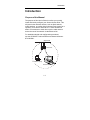
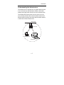
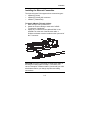
User’s Guide
Aironet 3500 Series™
AP3500-E Ethernet
Access Point
DOC-710-004020-A1
Aironet Wireless Communications, Inc. • 367 Ghent Road, Suite 300
P.O. Box 5292 • Fairlawn, Ohio 44334-0292
www.aironet.com
Aironet Wireless Communications, Inc.
No part of this document may be reproduced or transmitted in any means,
electronic or mechanical, for any purpose, without the written permission of
Aironet. Information in this document is subject to change without notice.
Aironet makes no representation or warranties with respect to the contents of
this manual and specifically disclaims any express or implied warranties of
merchantability or fitness for any particular purpose.
© 1998 Aironet Wireless Communications, Inc.
All rights reserved.
AP3500-E™, LM3500™, PC3500™, and Aironet™ are trademarks of Aironet
Wireless Communications, Inc.
Other trademarks used are properties of their respective owners.
Printed in USA
DOC-710-004020-A1
Manufacturers Federal Communication Commission
Declaration of Conformity Statement
Models: AP3500-E
Manufacturer:
Aironet Wireless Communications, Inc.
367 Ghent Rd , Suite 300
Fairlawn, OH 44334
1-800-3-WIRELESS
This device complies with Part 15 rules. Operation is subject to the
following two conditions:
1) this device may not cause harmful interference, and 2) this device must
accept any interference received, including interference that may cause
undesired operation.
This equipment has been tested and found to comply with the limits of a
Class B digital device, pursuant to Part 15 of the FCC Rules. These limits
are designed to provide reasonable protection against harmful interference
when the equipment is operated in a residential environment. This equipment generates, uses, and radiates radio frequency energy, and if not
installed and used in accordance with the instructions, may cause harmful
interference. However there is no guarantee that interference will not
occur. If this equipment does cause interference to radio or television
reception, which can be determined by turning the equipment off and on,
the user is encouraged to correct the interference by one of the following
measures:
l Reorient or relocate the receiving antenna.
l Increase separation between the equipment and receiver.
l Connect the equipment into an outlet on a circuit different from
which the receiver is connected.
l Consult the dealer or an experienced radio/TV technician.
User Warning
The Part 15 radio device operates on a non-interference basis with
other devices operating at this frequency. Any changes or
modification to said product not expressly approved by Aironet could
void the user’s authority to operate this device.
i
Department of Communications - Canada
Canadian Compliance Statement
This Class B Digital apparatus meets all the requirements of the Canadian
Interference-Causing Equipment Regulations.
Cet appareil numerique de la classe B respecte les exigences du
Reglement sur le material broilleur du Canada.
This device complies with Industry Canada certifications RSS-210
(unlicensed use) and GL-36/RSS-139-1 (licensed outdoor use). Operation
is subject to the following two conditions: 1) this device may not cause
harmful interference, and 2) this device must accept any interference
received, including interference that may cause undesired operation.
European Telecommunication Standards Institute
Statement of Compliance
Information to User
This equipment has been tested and found to comply with the European
Telecommunications Standard ETS 300.328. This standard covers Wideband Data Transmission Systems referred in CEPT recommendation T/R
10.01.
This type of accepted equipment is designed to provide reasonable
protection against harmful interference when the equipment is operated in
a commercial environment. This equipment generates, uses, and can
radiate radio frequency energy, and if not installed and used in accordance
with the instruction manual, may cause harmful interference to radio
communications.
ii
Declaration of Conformity
Aironet Model Number:
AP3500-E
Application of Council Directive:
Application of Council Directive:
CE Type Examination Certificate:
89/336/EEC
73/23/EEC
HDTP/RDR/167/394122
Standards to which Conformity is Declared:
EN 55022 (B)
EN 55011 (B)
EN 50082-1
EN 60950
Manufacturer:
Aironet Wireless Communications, Inc.
367 Ghent Road, Suite 300
Fairlawn Ohio, 44334
The undersigned hereby declares that the equipment specified
above conforms to the directives and standards cited herein.
Michael Smedley
Director, Manufacturing Engineering
Aironet Wireless Communications, Inc.
iii
Table of Contents
Introduction .................................................................... 1-1
Purpose of the Manual ............................................... 1-1
Safety Information ...................................................... 1-2
Dipole Antenna .................................................... 1-3
High Antennas ..................................................... 1-3
Other Devices in the Wireless Network .............. 1-3
Before You Start ........................................................ 1-4
Terminology ............................................................... 1-5
Understanding the Infrastructure ............................... 1-7
Installation ...................................................................... 2-1
Installing the Antennas .............................................. 2-1
Installing the Console Port Cable .............................. 2-2
Installing the Ethernet Connection ............................. 2-3
Attaching the AC/DC Power Pack
and Powering On ....................................................... 2-5
Viewing the Indicator Displays ................................... 2-6
Top Panel Indicators ........................................... 2-6
Back Panel Indicators ......................................... 2-8
Configuration .................................................................. 3-1
Accessing the Console System ................................. 3-1
Configuring the Access Point ..................................... 3-2
SSID Identifier (ESSID) ....................................... 3-2
Assigning an IP Address ..................................... 3-3
Verifying Association ........................................... 3-3
Technical Support .......................................................... 4-1
Technical Reference Manual ..................................... 4-1
Communications ........................................................ 4-1
Web Site .................................................................... 4-1
iv
Introduction
Introduction
Purpose of the Manual
The purpose of this User’s Guide is to allow you to easily
install and initially configure your Aironet Access Point. This
will permit other wireless devices, such as fixed stations,
mobile stations, or another Aironet Access Point (acting as a
repeater), to be able to associate to it. These will then be
able to communicate to each other over the radio network
and to the rest of the network via the Ethernet link.
For detailed technical and configuration procedures,
see the AP3500-E Technical Reference Manual document
#710-004021.
Wired LAN
Root Unit
Portable Laptop
End Node
1-1
Introduction
Safety Information
The FCC with its action in ET Docket 96-8 has adopted a
safety standard for human exposure to radiated frequency
(RF) electromagnetic energy emitted by FCC certified
equipment. The Aironet products meet the uncontrolled
environmental limits found in OET-65 and ANSI C95.1,
1991. Proper operation of this radio according to the
instructions found in this manual will result in the user
exposure to be substantially below the FCC recommended
limits.
®
U
®L
•
•
•
•
LISTED
Do not touch or move the AP3500 antenna while unit is
transmitting or receiving.
Do not hold any component containing a radio such that
the antenna is very close or touching any exposed parts
of the body, especially the face or eyes, while
transmitting.
Do not operate a portable transmitter near unshielded
blasting caps or in an explosive environment unless it is
a type especially qualified for such use.
Do not operate radio or attempt to transmit data unless
the antenna is connected, if not, the radio may be
damaged.
1-2
Introduction
Dipole Antenna
Always orient antenna such that it is at least 15 cm
(6 inches) away from your body.
High Antennas
High gain wall mount or mast mount antennas are
designed to be professionally installed and should be
located a minimum distance of 30 cm (12 inches) or
more from your body. Please contact your professional
installer, VAR, or antenna manufacturer for proper
installation requirements.
Other Devices in the Wireless Network
Refer to the User’s Guide and Technical Reference
Manual for the PC3500 or UC3500 for additional
important safety information.
1-3
Introduction
Before You Start
After unpacking the system, make sure the following items
are present and in good condition.
•
Ethernet Access Point 3500 Series™
•
Power Pack. The power pack will be either
120VAC/60Hz or 90-264VAC/47-63Hz to 12-18VDC,
whichever is appropriate for country of use.
•
Two standard 2dB Dipole Antennas
If any item is damaged or missing, contact your Aironet
supplier. Save all shipping and packing material in order to
repack the unit should service be required.
NOTE: Any remote antennas or associated coaxial cables
are ordered and packed separately.
1-4
Introduction
Terminology
When configuring your system, and when reading this
manual, keep in mind the following terminology:
Infrastructure – The wireless infrastructure is the
communications system that combines Aironet Access
Points, mobile stations and fixed stations. Aironet Access
Points within the infrastructure can be either root units,
which are physically wired to the LAN backbone, or can act
as wireless repeaters. Other RF enabled devices serve as
fixed stations or mobile stations.
Cell – A single Aironet Access Point transmits and receives
data within an area called a cell. A cell is the area of radio
range (coverage) in which the Access Point can
communicate to other devices in the wireless infrastructure.
The size of a single cell depends upon the speed of the
transmission, the type of antennas used, the physical
environment as well as other factors. The size of the entire
coverage area for the wireless infrastructure can be
increased by adding Access Points, thus adding cells.
Root Unit – The root unit is an Aironet Access Point that is
located at the top, or starting point, of a wireless
infrastructure. The root unit provides the physical connection
to the wired LAN (such as Ethernet) and contains
configuration information in its association table that covers
all stations in the infrastructure.
Repeater – A repeater is an Aironet Access Point that
extends the radio range of the infrastructure. A repeater is
not physically attached to the wired LAN, but communicates
via radio to another Access Point, which is either a root unit
or another repeater.
1-5
Introduction
Radio Node – A PC, file server, notebook computer, etc.
containing a Radio Card or LAN Adapter.
End Node – A radio node that is located at the end of the
Network Tree.
Parent/Child Node – Refers to the relationships between
nodes in the wireless infrastructure. The complete set of
relationships is sometimes described as a Network Tree.
For example, the Aironet Access Point (at the top of the
tree) would be the parent of the end nodes. Conversely, the
end nodes would be the children of the Aironet Access
Point.
Association – Each root unit or repeater in the
infrastructure contains an association table that controls the
routing of packets between the LAN backbone and the
wireless infrastructure. The association table maintains
entries for all the stations situated below the Aironet Access
Point on the infrastructure including repeaters and radio
nodes.
Power Saving Protocol (PSP) and Non-Power Saving
Protocol – The Power Saving Protocol allows computers
(usually portable computers) to power up only part of the
time to conserve energy. If a radio node is using the Power
Saving Protocol to communicate with the network, the
Aironet Access Point must be aware of this mode and
implement additional features such as message store and
forward.
1-6
Introduction
Understanding the Infrastructure
The infrastructure is designed like an upside-down tree with
a root unit at the top and repeaters, stations, and mobile
stations branching down from the root unit as shown below.
The AP3500-E Aironet Access Point can serve as a root
unit, providing wireless data communications between the
Ethernet based networks and other stations/mobile stations
or within the wireless infrastructure.
Wired LAN
Root Unit
Portable Laptop
End Node
1-7
Introduction
In the example, the Access Point maintains an area of RF
coverage (cell). Any radio node within the cell’s area can
communicate to any other node (via radio or across the
wired Ethernet LAN) using the Access Point.
If a larger area of RF coverage is required, additional
Access Points can be added either as root units, attached to
the LAN, or as repeaters. Each Access Point adds its own
cell, which can be used to provide additional coverage area,
greater total bandwidth, or network redundancy.
For information about how to configure the AP3500-E as a
repeater or other networking and system configuration
issues, see the AP3500-E Technical Reference Manual
document #710-004021.
Information about optional long range antennas is available
from the Aironet Antenna Guide document #710-003725 or
your Aironet supplier.
1-8
Installation
Installation
This section describes the procedures for installing the
Aironet Access Point.
Installing the Antennas
The AP3500-E comes with two antennas.
1. With the unit powered off, attach both antennas to the
antenna connectors.
10Base5
10BaseT
10Base2
NOTE: Do not over-tighten; finger tight is sufficient. Position
the antennas vertically for best omni-directional signal
reception.
2. If you are using the Aironet Access Point with a remote
antenna, connect the coaxial cable to the antenna
connector. Only use antennas and cables supplied by
Aironet Wireless Communications.
NOTE: Due to FCC and DOC Regulations, the antenna
connectors on the Aironet Access Point are of reverse
polarity to the standard TNC connectors.
2-1
Installation
Installing the Console Port Cable
1. Attach the Console Port cable to the serial port. Attach
the other cable end to the serial port on a terminal or a
PC running a terminal emulation program. Use a 9-pin
male to 9-pin female straight through cable.
NOTE: This connection is required for setting up initial
configuration information. After configuration is
completed, this cable may be removed until additional
configuration is required via the serial port.
2. Set the terminal to 9600 Baud, No-Parity, 8 data bits,
1 Stop bit, and ANSI compatible.
2-2
Installation
Installing the Ethernet Connection
The Aironet Access Point supports three connection types:
• 10Base2 (Thinnet)
• 10Base5 (Thicknet) AUI connector
• 10BaseT (Twisted Pair)
To Attach 10Base2 (Thinnet) Cabling:
1. Make sure the unit is powered off.
2. Attach the Thinnet cabling to each end of a BNC
T-connector, if applicable.
3. Attach the T-connector to the 10Base2 BNC. If the
AP3500-E is at the end of the Ethernet cable, a
50-Ohm terminator must be installed on the open end of
the T-connector.
10Base5
10BaseT
10Base2
CAUTION: Removing a terminator to install extra cable, or
breaking an existing cable to install a T-connector, will
cause a disruption in Ethernet traffic. Consult with your LAN
administrator before you change any Ethernet cabling
connections.
2-3
Installation
To Attach the 10Base5 (Thicknet) Cabling:
1. Make sure the unit is powered off.
2. Attach the transceiver connector to the 10Base5 AUI
port.
3. Slide the locking mechanism in place.
4. Attach the other end of the transceiver drop cabling to
an external transceiver.
10BaseT
10Base5
10Base2
To Attach the 10BaseT (Twisted Pair) cabling:
1. Make sure the unit is powered off.
2. Plug the RJ-45 connector into the 10BaseT (Twisted
Pair).
3. Connect the other end of the Twisted Pair cabling to the
LAN connection (such as a hub or concentrator).
10Base2
10Base5
10BaseT
2-4
Installation
Attaching the AC/DC Power Pack
and Powering On
1. Insert the small plug on the end of the AC/DC power
pack cord into the power port.
2. Plug the AC/DC power pack into an electrical outlet.
(120 VAC or 90-264 VAC as appropriate)
3. Power on the Aironet Access Point by pushing the
On/Off button.
On/Off Button
When power is initially applied to the Aironet Access Point,
all three indicators will flash in sequence to test the
functionality of the indicators.
2-5
Installation
Viewing the Indicator Displays
Top Panel Indicators
The indicators are a set of displays located on the top
panel of the Aironet Access Point unit.
•
•
•
Ethernet Indicator - Used to indicate Ethernet
network traffic activity. The light is normally off, but
will flash green whenever a packet is received or
transmitted over the Ethernet interface.
Status Indicator - Shows solid green when the
Aironet Access Point has accepted a radio
association.
Radio Indicator - Used to indicate radio traffic
activity. The light is normally off, but will flash green
whenever a packet is received or transmitted over
the radio.
When the Aironet Access Point is initially powered up,
all three displays will flash amber, red and then green, in
sequence. If a power-on test fails, the status indicator
will go solid red and the unit will stop functioning. See
Table 1.1 for a detailed explanation of the Top Panel
indicators.
Ethernet
Status
Radio
2-6
Installation
Table 2.1 – Top Panel Indicator Description
Type
Nonassociated
Station
Indicator Display
Ethernet
Status
Radio
Blinking
Green
Green
Green
Blinking
Green
Operational
Blinking
Green
Green
Green
Error/Warning
Blinking
Amber
Blinking
Amber
Green
Blinking
Amber
Failure
Firmware
Upgrade
Red
Red
Red
2-7
Red
Description
No nodes
associated
One or more
nodes
associated
Transmitting/
Receiving
Radio packets
Transmitting/
Receiving
Ethernet
packets
Maximum
retries/buffer
full occurred
on radio
Transmit/
Receive errors
General
warning,
check the logs
Software
failure
Flashing the
firmware
Installation
Back Panel Indicators
The back panel indicators are:
•
•
•
•
•
•
10BaseT polarity: Solid amber to indicate the
10BaseT polarity is reversed. Check cable
connections.
10BaseT active: Solid green to indicate the 10BaseT
has been configured as the active port.
Ethernet Rx: Flashes green when an Ethernet packet
has been received.
Ethernet Tx: Flashes green when an Ethernet packet
has been transmitted.
10Base2 active: Solid green to indicate the 10Base2
has been configured as the active port.
Packet Collision: Flashes amber to indicate a packet
collision has occurred.
10BaseT polarity
Packet
Collision
Ethernet Tx
Ethernet Rx
10Base2 active
2-8
10BaseT active
Configuration
Configuration
This section describes the methods used to access and
configure the Console system of the Aironet Access Point.
This system contains all commands necessary to initially
configure and monitor the operation of the unit.
Accessing the Console System
There are many ways in which you may configure and
monitor the Aironet Access Point. When the unit is first
powered up, basic configuration must initially be performed
by accessing the Console serial port.
To gain access through the serial port, the Aironet Access
Point must be connected to a terminal or a PC running a
terminal emulation program. Set the terminal to 9600 Baud,
No-Parity, 8 data bits, 1 stop bit, and ANSI compatible.
The Console system is organized as a set of menus. Each
selection in a menu list may either take you to a sub-menu
or display a command that will configure or display
information controlling the unit.
Once the Aironet Access Point has been assigned an IP
address, you may then access the Console remotely using:
•
•
•
Telnet protocol from a remote host or PC
HTML browser, such as Netscape Navigator from a
remote host
Simple Network Management Protocol (SNMP) from a
remote network management station
3-1
Configuration
Configuring the Access Point
To configure the Aironet Access Point so it will communicate
with other stations or repeaters, use the Console Port to set
the SSID parameter.
If you choose to set an IP address, remote access via telnet
or an HTML browser will be possible.
SSID Identifier (ESSID)
The SSID is a unique identifier that is attached to
selected packets sent out over the radio network. This
functions as a password to join the radio network.
Stations associating to the Aironet Access Point must
use the same identifier in their configurations, or their
association requests will be ignored.
To define an SSID:
1. Select Configuration from the Main Menu.
2. Select Radio from the Configuration Menu.
3. Select ESSID.
4. Enter a value for the SSID option. You may use up
to 32 characters. All devices in the same radio
network must use the same SSID.
3-2
Configuration
Assigning an IP Address
An IP address must be assigned to the unit before it can
be accessed by telnet, HTTP, or SNMP. Other detailed
internet addressing options (such as gateway address,
SNMP routing, etc.) can also be defined. Refer to the
Technical Reference Manual document #710-004021
for further details.
To assign an IP address:
1. Select Configuration from the Main Menu.
2. Select Ident from the Configuration Menu.
3. Use the INADDR option to establish an IP address.
4. Use the INMASK option to define the internet mask,
as appropriate.
Verifying Association
Once you have configured the Aironet Access Point and
station devices with the correct parameters, the Radio
Indicator will flash green indicating RF data traffic. The
Status Indicator will be solid green indicating one or
more stations have associated to the Aironet Access
Point.
3-3
Technical Support
Technical Support
Technical Reference Manual
Use the Technical Reference Manual document
#710-004021 to learn more about your Aironet unit.
Communications
Use the following information to contact the Aironet
Technical Support group:
Telephone - (330) 664-7903
Fax (330) 664-7990
e-mail [email protected]
Web Site
For additional product information and technical support,
including the capability to download new firmware and
drivers, use the Aironet web site at:
http://www.aironet.com
4-1
Technical Support
4-2