1
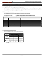
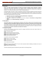
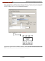
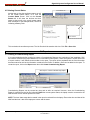
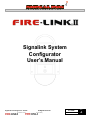
T E C H N O L O G I E S
I N C .
Signalink System
Configurator
User’s Manual
Signalink Technologies Inc. © 2010
is a member of the
All Rights Reserved
product family
077.0046
2 FEB 2010
Rev
A
Signalink System Configurator User’s Manual
Table of Contents
1.0 General Product Information ............................................................................................................................................. 3
1.1 *** IMPORTANT *** Site Prequalification Requirement ............................................................................................... 3
1.2 Documentation Reference ............................................................................................................................................ 3
1.3 Applicable System Components ................................................................................................................................... 3
1.4 Key Features of SSC .................................................................................................................................................... 4
1.5 Minimum System Requirements ................................................................................................................................... 4
1.6 Dealer Kit ...................................................................................................................................................................... 4
2.0 SSC Installation ................................................................................................................................................................. 5
2.1 Installation Quick Start .................................................................................................................................................. 5
3.0 SSC Overview ................................................................................................................................................................... 7
3.1 Overview ....................................................................................................................................................................... 7
3.2 The Job File .................................................................................................................................................................. 7
3.3 Programming Steps ...................................................................................................................................................... 7
4.0 Using the Configurator ...................................................................................................................................................... 8
4.1 Starting up the Configurator.......................................................................................................................................... 8
4.2 Creating a New Job File ............................................................................................................................................... 9
4.3 Entering Devices into the Device List ......................................................................................................................... 10
4.4 Connecting Serial Cable to the NMC .......................................................................................................................... 11
4.5 Connecting to the NMC .............................................................................................................................................. 12
4.6 Sending Job to Panel.................................................................................................................................................. 14
4.7 SSC Status Bar ........................................................................................................................................................... 14
4.8 Enrolling ISDs ............................................................................................................................................................. 15
4.9 Viewing Current Status ............................................................................................................................................... 16
5.0 Reports ............................................................................................................................................................................ 16
5.1 Creating a Commissioning Report .............................................................................................................................. 16
5.2 Interpreting the Commissioning Report ...................................................................................................................... 18
5.3 Saving the Commissioning Report ............................................................................................................................. 18
6.0 Event Logs ...................................................................................................................................................................... 19
6.1 Retrieving the Event Logs........................................................................................................................................... 19
6.2 Opening a Saved Event Log ....................................................................................................................................... 20
7.0 Post Installation ............................................................................................................................................................... 20
7.1 Laptop / NMC Synchronization Overview ................................................................................................................... 20
7.2 Get Job, Send Job, Compare Job .............................................................................................................................. 22
8.0 Miscellaneous ................................................................................................................................................................. 23
8.1 Editing the Device List ................................................................................................................................................ 23
8.2 Adding a Device to the Device List ............................................................................................................................. 23
8.3 Deleting the NMC’s Device List .................................................................................................................................. 23
8.4 Changing the Profile ................................................................................................................................................... 23
8.5 Importing Earlier Version Job Files ............................................................................................................................. 23
8.6 Using the Bar Code Scanner ...................................................................................................................................... 24
Signalink Technologies Inc. © 2010
All Rights Reserved
077.0046 REV A
Page 2 of 28
Signalink System Configurator User’s Manual
1.0 General Product Information
1.1 *** IMPORTANT *** Site Prequalification Requirement
The Fire-Link®II Site Prequalification form must be completed by the dealer or installer AND approved by Signalink
Technologies prior to installation of any Fire-Link® equipment. Equipment and/or installation warranties may be void
if this installation is not approved by Signalink Technologies.
1.2 Documentation Reference
The chart below lists the pertinent documentation to install Fire-Link®II equipment.
This is Document Number:
077.0046 – Signalink System Configurator User’s Guide
Fire-Link® II
Documentation Reference
Document Number
Document Name
Description
077.0024
NMC and TPC Installation Guide
Installation and 120V Wiring of the NMC, TPC and CHK-400
077.0050
TPC Installation Guide
TPC and CHK-400 Installation Instructions (Enclosed in TPC Unit Box)
077.0048
NMC Fire Alarm Wiring Guide
NMC Fire Alarm and Fire Alarm Control Panel (FACP) Interconnect Wiring
077.0049
ISD Installation, Operation and Maint. Guide
ISD Installation, Operations and Maintenance Guide
077.0045
NMC Programming Manual
NMC and ISD Programming and Set Up
077.0046
Signalink System Configurator User’s Manual
System Configurator User’s Guide for NMC Programming Via Laptop
077.0025
Building Manager’s Guide
NMC and ISD Operation, Test and Inspection Guide
1.3 Applicable System Components
This document applies to the following system components:
Signalink Technologies Inc. © 2010
All Rights Reserved
077.0046 REV A
Page 3 of 28
Signalink System Configurator User’s Manual
1.4 Key Features of SSC
The Signalink System Configurator (SSC) is a laptop software application that allows the programming of the NMC
via a laptop computer. It is convenient and simple to use and offers greater flexibility in programming and system
start-up than manually configuring the system from the NMC keypad. Some of the key features of the SSC include:
•
•
•
•
•
•
•
The ability to create “Job” files, including the NMC Device List and Configuration data, and store them on the
laptop.
The ability to use a bar code scanner to scan the ISDs’ VIDs rather than manually entering the VID data.
The ability to easily manage the Device List from the laptop rather than at the NMC.
The ability to create the Job files remotely without having to be on-site and / or at the NMC controller.
The ability to retrieve Event Logs from the NMC and store them with Job file.
The ability to create and print post installation commissioning reports.
The ability to run certain system diagnostics that are not available on the NMC
SSC installs quickly and easily from the Installation CD or from the web site download.
1.5 Minimum System Requirements
SSC installs and runs on most laptop computers with the following minimum requirements:
500 MHz or faster processor
Windows® XP Home, XP Professional with Service Pack (SP2), Vista
256 MB RAM
CD ROM Drive
1 GB available hard-disk space
1 available USB port or RS-232 serial port (to connect to the NMC)
NOTE: This software application will not run on Windows® 95 or Windows® 98 or early versions of Windows®
NOTE: This software application is not available for MAC.
1.6 Dealer Kit
A Dealer Kit is recommended when using the SSC. The Dealer Kit contains:
1 - SSC Installation CD (which include)
SSC Installation Software
Soft Copy Manuals (PDF Format)
Release Notes and other technical information
1 - USD to Serial Adapter (for connecting to the NMC)
1 - Serial Cable (for connecting to the NMC)
1 - Bar Code Scanner*
The Dealer Kit is available from the Distributor or from Signalink Technologies.
*The bar code scanner is recommended for scanning the ISDs’ VID rather than entering the data manually. It greatly
reduces the amount of time required to enter the data and may prevent data entry errors.
Signalink Technologies Inc. © 2010
All Rights Reserved
077.0046 REV A
Page 4 of 28
Signalink System Configurator User’s Manual
2.0 SSC Installation
2.1 Installation Quick Start
Step 1
Insert the installation CD into the laptop. The installation software will automatically run the set-up
program.
Step 2
The following screen will appear. Click Install.
When the Setup has completed, the following pop-up will appear. Click OK.
The following screen will appear. The default Folder Path for all SSC files is C:\Documents and
Settings\Office\My Documents. In Windows®, this is referred to as “My Documents”. If a different
folder is preferred, click the
icon to the right of the Folder Path field and the explorer screen in
Step 4 will appear.
Step 3
Signalink Technologies Inc. © 2010
All Rights Reserved
077.0046 REV A
Page 5 of 28
Signalink System Configurator User’s Manual
Step 4
Step 5
Navigate to or create a different folder as desired. Once the folder has been selected, click Save. The
file “JobList” will be created in the folder chosen.
Finish filling out the information in Profile dialog box. The “Country” field is required as this will prepopulate the NMC Model in the Job file. The “Access Code” is for access to special diagnostic and
critical engineering functions. Leave it blank. When all the fields are completed, click OK.
***** Installation is of the Signalink System Configurator is complete! *****
Signalink Technologies Inc. © 2010
All Rights Reserved
077.0046 REV A
Page 6 of 28
Signalink System Configurator User’s Manual
3.0 SSC Overview
3.1 Overview
Refer to the NMC Programming Manual (077.0045) for information regarding system configuration, parameter
settings and other system requirements. The Signalink System Configurator (SSC) provides a means of
programming the NMC via a laptop. This document explains the how to use the SSC software but the configuration
settings etc., are explained in greater detail in the NMC Programming Manual.
Programming NMC via the SSC is similar to programming the NMC manually with regards to the tasks required and
the order in which they need to be performed. As with programming the NMC manually, knowing how the system is
to be configured prior to programming will save time and repeated steps. Below is a list of parameters that should be
known prior to programming the SSC and the NMC.
•
•
•
•
NMC Mode configurations: Accessory, Accessory With Strobe or Stand-Alone.
NMC Model configurations: US or Canadian
If the NMC is configured as a Stand-Alone unit, the time settings for: Auto Silence and Signal Silence
Inhibit
ISD Alarm Type: Temporal, Marching or Continuous.
3.2 The Job File
The file that contains all of the job information is called the Job file. When created, the Job file contains the job site
information, the Device list and NMC configuration settings. The Job file can be created any time and can be created
remotely without being connected to the NMC. When connected to the NMC, the Job file must sent to the NMC which
sets the NMC configuration settings and downloads the Device list into the NMC. When connected to the NMC, the
event logs can be retrieved from the NMC. The log information is also stored in the Job file. In essence, the Job file
contains all of the information associated with that particular installation.
3.3 Programming Steps
There are a few programming steps that are required to program the NMC and start up the system. Below is an
abbreviated step-by-step instruction.
STEP 1: Create the Job file
STEP 2: Enter the site and contact information
STEP 3: Enter the NMC configuration information
STEP 4: Enter the ISDs into the Device list
STEP 5: Save and close the Job file
At the NMC, connect the laptop to the NMC.
STEP 6: Open the Job file created
STEP 7: Send the Job file to the NMC
STEP 8: Start Enrollment
Once enrollment has completed:
STEP 9: Get the Job from the NMC. This will retrieve important network addressing information that may be
necessary for diagnostic purposes.
STEP 10: Save and close the Job file.
The above programming steps are explained in greater detail in the following Sections.
Signalink Technologies Inc. © 2010
All Rights Reserved
077.0046 REV A
Page 7 of 28
Signalink System Configurator User’s Manual
4.0 Using the Configurator
4.1 Starting up the Configurator
To start the Signalink System Configurator (SSC), click the on the Windows® Start button, and then click All
Programs. Click on the Signalink program bar and then click the SSC Icon. Alternatively, click on the SSC Icon
located on the desk top.
Click Start
Click All Programs
Click on Signalink then Click the SSC Icon
The following screen will appear. This is the SSC Main Screen.
SSC Main Screen
Signalink Technologies Inc. © 2010
All Rights Reserved
077.0046 REV A
Page 8 of 28
Signalink System Configurator User’s Manual
4.2 Creating a New Job File
To create a New Job File, click the Create New Job button on the SSC Main Screen. In the New Job Name pop-up
screen, enter a new Job name then OK.
Click Create New Job
Enter New Job Name
The following screen will appear: Note that the screen tab is Job and the Job Name is what was entered above
Screen Tabs
Job Name
Site Info
NMC Model
Contact Info
NMC Mode
ISD Signal Rate
Notes
Signalink Technologies Inc. © 2010
All Rights Reserved
077.0046 REV A
Page 9 of 28
Signalink System Configurator User’s Manual
Enter the Site information, any Contact information and any Notes. The Site information is used on the reports if any
are generated. The Contact information and Notes are for reference.
Select the NMC Model (US or Canadian). This will default to the Country setting that is selected in the Profile. See
Step 5 of Section 2.1 (Installation Quick Start).
Select the NMC Mode (Standalone, Accessory or Acc + Strobe). Refer to the Programming Manual for explanation
of NMC Modes.
Select the Device Signal Rate. This is ISD signaling rate.
This is a good time to save this Job file. In the upper left corner of the screen, click File > Save Job.
4.3 Entering Devices into the Device List
Use of a bar code scanner to scan the ISDs’ VID is highly recommended when creating the Device list. It saves time,
reduces the amount of typing and may prevent data entry errors. The bar code scanner is included in the Dealer Kit.
See Section 8.6 – Using the bar code scanner.
On the SSC Main Screen, click on the Devices tab. The following will appear.
Devices Tab
ISD Location
ISD VID
Enter the location of the ISD. It is generally the suite number or physical location. This field can be up to 8 alphanumeric characters, upper or lower case. Dashes are allowed but NO spaces or any other special characters.
After the location is entered, tab over to or click in the VID field. If using a scanner, scan the VID. When scanned, the
scanner should beep and automatically advance to the next device to be added. If manually entering the VID, enter
the VID then press ENTER or ADD.
NOTE: Duplicate Locations and duplicate VIDs are NOT permitted. If more than one ISD is required in a particular
location, use a suffix such as -A or -1, etc.
Signalink Technologies Inc. © 2010
All Rights Reserved
077.0046 REV A
Page 10 of 28
Signalink System Configurator User’s Manual
As devices are added to the Device list, they will appear in the Device list table. It will list the ISDs’ location and VID.
It also gives a count of the number of devices in the list. The other information in the table is gathered from the NMC
during and after enrollment. This information is discussed in Section 5 - Reports.
ISD Device Count
ISD Device List
Once the Device list has been completed, save the Job file. Click File > Save Job.
4.4 Connecting Serial Cable to the NMC
Once the Job file has been created, the laptop needs to be connected to the NMC to download the Job file into the
NMC. If the laptop has an RS232 serial port, connect the serial cable to the serial port. If the laptop only has USB
ports, a USB to Serial adapter is required. This adapter is included in the Dealer Kit. If this is the first time a USB to
Serial adapter is used on the laptop, the driver software for the adapter may need to be installed. Follow the
manufacturer’s instructions included with the USB to Serial adapter to install the driver software. Connect the serial
cable to the USB adapter. Remove the dead front on the NMC to gain access to the RS232 (DB9) connector and
plug the serial cable into the connector J118.
FIRE
ALARM
ALARM
SILENCE
ALARM
SILENCE
RESET
USB-Serial
Adapter
POWER
ACK
MENU
1
_-‘
2
ABC
3
DEF
4
GHI
5
JKL
6
MNO
7
8
TUV
WXYZ
PQRS
Serial Cable
SYSTEM
TROUBLE
*
shift
0
9
#
space
J118
NOTE: A Ground Fault trouble may be displayed on the NMC when the cables are connected to the NMC. This is a
ACK
normal condition. Press the
key on the NMC Keypad to silence the buzzer.
Signalink Technologies Inc. © 2010
All Rights Reserved
077.0046 REV A
Page 11 of 28
Signalink System Configurator User’s Manual
4.5 Connecting to the NMC
If the SSC software has been shut down or exited, restart SSC. Open the desired Job file. To open the Job file, click
on the File > Open Job, OR click on the Open Existing Job Button OR click on the Job Name pull down and click
on the appropriate Job file. This becomes the Active Job, meaning it is current Job that is open in SSC.
Click File > Open Job
Click on Desired Job File
Click on Pull Down
Open an Existing Job
Once the cables are connected to the NMC and the Job file is open, click on the Communications pull down menu
and click Connect, or press F10 at any time.
Communications Pull Down
The bottom Status Bar will indicate the connection status. If the wrong Com port is selected or if there is some other
problem with the connection, the Connection Attempt count will continue to increase since it can’t establish
connection. The most common cause is an incorrect Com port selection. To change the Com port, click Change
Comm Port on the Communications pull down and select a different Com Port. If it still fails to connect, a cabling
problem may be the issue.
Connection Status
Signalink Technologies Inc. © 2010
All Rights Reserved
077.0046 REV A
Page 12 of 28
Signalink System Configurator User’s Manual
When communications is established with the NMC, the Status Bar Connection Status will indicate Panel
Connected [VID] where VID is the VID address of the NMC. In this example, the VID of the panel is 77364900. On
the NMC LCD display, NMC will also indicate Connected To Computer.
Job Association
Panel Connected
FIRE
ALARM
ALARM
SILENCE
SYSTEM
TROUBLE
POWER
Connected to
Computer
RESET
ALARM
SILENCE
ACK
MENU
NMC Display when connected
Once connected, a pop-up window will appear and prompt the user: Do you want to associate this panel with this
job [Job file name]. This will record the NMC’s VID with the Job file and link the Job file name with the VID of the
NMC. Click Yes. Job Association is discussed in Section 7 – Post Installation.
Signalink Technologies Inc. © 2010
All Rights Reserved
077.0046 REV A
Page 13 of 28
Signalink System Configurator User’s Manual
4.6 Sending Job to Panel
The next task is to send the Job file, which contains the Device list and NMC configuration to the panel. Click on the
Panel menu and click Send Job to Panel.
Click Panel > Send Job to Panel
When the Job file has been successfully sent to the NMC, the status bar will indicate Panel Synchronized, meaning
that the Job file on the laptop matches, or is synchronized, with the NMC.
Panel Synchronized
4.7 SSC Status Bar
Below is a view of the SSC Main Menu Status Bar. The status bar shows the connection status and other information
regarding the connection state with the NMC.
1
Indicates which Com. Port is Opened on the laptop
2
Indicates the number of attempts the laptop is trying to establish communications with the NMC or
Indicates the NMC is connected and the VID of the NMC
3
When the laptop is connected to the NMC, it constantly gathers data (Records) from the NMC. This is the
record count of the number of records received from the NMC.
4
Capture is a special diagnostic function that collects certain network protocol information. The Capture
function is a special function and is normally On when connected, Off when not connected.
5
Panel / Job file Synchronization. When the laptop is connected to the NMC, and when instructed to do so, the
laptop will compare the information in the Job file to the information in the NMC. If the information between the
Job file and the NMC are not the same, the laptop and the NMC are NOT Synchronized. When the information in
Job file and the information in the NMC are the same, the laptop and the NMC are considered Synchronized. See
Section 7 – Post Installation regarding Synchronization.
1
Signalink Technologies Inc. © 2010
All Rights Reserved
077.0046 REV A
2
3
4
5
Page 14 of 28
Signalink System Configurator User’s Manual
4.8 Enrolling ISDs
Once the Job file has been sent to the NMC and the panel and laptop are synchronized, the ISDs must now be
enrolled. Reference the NMC Programming Manual for discussion on enrollment. To enroll the ISDs, click on the
Panel menu then click Start Enrollment, or press F5 at any time. Enrollment can only commence if the Job file and
NMC are Synchronized. See Section 7 – Post Installation.
IMPORTANT
All ISD MUST be plugged in and powered up prior to starting enrollment. The enrollment process will struggle and
may take a considerable amount of time to complete.
Click Panel > Start Enrollment
The enrollment status can be viewed in a couple of ways. On the Devices Tab, the Status column shows that status
of each ISD, including any problems that may exist.
NOTE: Most fields in SSC have a Mouse-Over feature meaning when the mouse is over a particular field, a message
or definition pop-up box will appear. In this case, the red mouse cursor resting over the Status column shows a
definition of all of the letters in the status column. “E” indicates that the devices are enrolled.
Device Status
Mouse Over Status Definition
Signalink Technologies Inc. © 2010
All Rights Reserved
077.0046 REV A
Page 15 of 28
Signalink System Configurator User’s Manual
4.9 Viewing Current Status
Current Status Tab
Another way to view the enrollment status, as well
as the overall system status, is to view the
Current Status screen. Click on the Current
Status tab. It will show the devices and their
status as they enroll or the overall system status
after enrollment. In the example below, 1 device is
indicating a Battery Fault
Device VID
Device Location
This concludes the enrollment process. The Job file should be saved at this time. Click File > Save Job.
5.0 Reports
5.1 Creating a Commissioning Report
It is recommended and often required to create a Commissioning Report at the conclusion of the installation. SSC
will create a commissioning report based on the current status of the system. If there are System Troubles at the time
of report creation, it will indicate those troubles in the report. The report will be populated with the Site information
that was entered as well as the information contained in the Profile. In addition, notes can be added to the report. To
create the report, click on the Report menu then click Create Commissioning Report.
Click Report > Create Commissioning Report
Commissioning Reports can be created any time and as often as required. However, since the Commissioning
Report is created from the Job file information AND the current system status, the laptop must be connected to the
NMC with the correct Job file opened in the SSC.
NOTE: The time / date stamp that is created in the report is retrieved from the laptop. Ensure the time and date of the
NMC and the time / date of the laptop are correct and the same.
Signalink Technologies Inc. © 2010
All Rights Reserved
077.0046 REV A
Page 16 of 28
Signalink System Configurator User’s Manual
This is a typical Commissioning Report. Most of the information is automatically generated however some fields
should be filled in manually. The report can be edited as need with notes and other observations anywhere on the
form..
Site Information
Installer Information
Current Status
ISD Diagnostic Information
NMC Test Information
NOTE: The Panel Tests (NMC) are manual tests, such as measuring the battery voltage, etc. These tests and their
results should be typed directly into the Report.
Ground Fault: To create a ground fault, use a wire to place a chassis ground on the NEGATIVE (-) battery terminal.
The most convenient chassis ground is the wing nut used to for the door ground strap located on the left side of the
NMC back box.
Warning
Care MUST be taken not to short any of the circuitry on the circuit boards or on the AC Power circuits.
Use ONLY the CHASSIS ground for this test. THIS TEST IS OPTIONAL. DO NOT perform this test if uncertain.
Battery Voltage: Remove the battery leads and measure the battery terminal voltage. If this is a new Commissioning
Report on a newly installed system, a few hours may be needed for the battery to reach a reasonable charge state.
Lamp Test: The Lamp Test is performed by pressing the Lamp-Test keys
simultaneously.
*
shift
0
#
space
LAMPTEST
Test Results: To record the Pass / Fail condition of the NMC test, simply highlight the opposite result and press the
delete key on the laptop. To enter the Battery Voltage, place the cursor on the Battery Voltage line and type in the
measured voltage.
Other tests and notes can be added anywhere on this form.
Signalink Technologies Inc. © 2010
All Rights Reserved
077.0046 REV A
Page 17 of 28
Signalink System Configurator User’s Manual
5.2 Interpreting the Commissioning Report
Below is a chart describing the how to interpret the information within the report.
5.3 Saving the Commissioning Report
To save the report, click Report > Save Commissioning Report. In the explorer window, select the folder that is
associated with the Job file, give the Report a name if the default name is not desired, then click Save.
Click Report > Save Commissioning Report
Choose Job File Folder
NOTE: Once the report has been saved, it can
be reopened and printed at any time. To open
an existing report, click Report > Open
Commissioning Report.
Default Report Name
Signalink Technologies Inc. © 2010
All Rights Reserved
077.0046 REV A
Page 18 of 28
Signalink System Configurator User’s Manual
6.0 Event Logs
6.1 Retrieving the Event Logs
The Event Logs assist in troubleshooting the system and are often request by Signalink Technologies Technical
Support Staff. The Event Log contains all of the Trouble logs, Alarm logs and Audit logs. They are saved in the same
Job folder as the Job file. To retrieve the Event Logs, the laptop must be connected to the NMC and the correct Job
file opened in SSC. To retrieve the Event Logs, click on the Panel menu then click Get Event Logs. It may take a
moment to retrieve the Event logs depending on the amount of information in the logs.
Click Panel > Get Event Logs
The report will appear as shown below on the Event Logs tab. By default, the data is arranged and sorted by Audit
log first, Trouble log second and Alarm log third. The entire list can be sorted by device if desired.
Standard Report
Click to Sort by Device
NOTE: The Event Log is saved with the Job file is saved. The Event Log is saved with the following name and
format:
TroubleLogYYYYMMDD HHMMSS
Where YYYY = Year, MM = Month, DD = Day, HH = Hour (24 hour format), MM = Minute, SS = Second
As an example, if retrieved March 23rd, 2010 at 1:04:32 PM, it will appear in the Job folder as
TroubleLog20100223 130432
Signalink Technologies Inc. © 2010
All Rights Reserved
077.0046 REV A
Page 19 of 28
Signalink System Configurator User’s Manual
6.2 Opening a Saved Event Log
To open an existing Event Log saved on the laptop, ensure the appropriate Job file is opened in SSC then click File
> Open Trouble Log File. The explorer screen will open and the list of saved Event Logs will be shown. The file
names of the Event Logs are described above. Double click on the desired Log file (or click the file then click Open).
The Log file will be displayed in the Event Logs Tab.
Opens in the Event Logs tab
Double Click Desired File
7.0 Post Installation
7.1 Laptop / NMC Synchronization Overview
Once a Fire-Link® System has been installed and commissioned, the NMC will retain its configuration and device
information indefinitely. However, changes can be made to the NMC via the front panel or other means that may not
get reflected into the Job file that created it. Likewise, there are things that may change on the laptop that are not
reflected in the NMC. In either case, when the information in the Job file is different than the information in the NMC,
they are not Synchronized. There are several different methods for synchronizing the laptop and the NMC, however
if done incorrectly, it may produce undesirable results. Understanding what certain actions do will assist in making an
informed decision. The discussion and flow chart below will preface the actions required for accurate
synchronization.
Job Association: SSC requires the association of a specific Job file to a specific NMC. Essentially association
means the Job file and the NMC’s VID are referenced as a pair. When connection is made to the NMC, SSC will
prompt the user at some point to associate a Job file to the connected NMC. This association is stored in a
completely different file, other than the Job file, named JobList. If the user chooses not to associate a Job file to the
connected NMC, no association made and connection to the NMC is terminated. There can only be one Job file
associate to a specific NMC. If a different Job file is required to be associated with the connected NMC, SSC will
disassociate the currently associated Job file and re-associate the different Job file.
Signalink Technologies Inc. © 2010
All Rights Reserved
077.0046 REV A
Page 20 of 28
Signalink System Configurator User’s Manual
Flowchart Terminology:
Active Job File
Associated Job: The Job file that is associated with the
connected NMC.
Non-Associated Job: A Job file that is NOT associated
with the connected NMC. The Non-Associated Job file
may however be associated to a different NMC.
Active Job: The Job file that is currently active in SSC
when connection is made to the NMC. It can be the
Associated Job, the Non-Associated Job or simply no
Job.
Below is a flowchart of what happens at the time of connection to the NMC and is based on certain conditions and
decisions.
Note: Connection to an NMC that is not associated to a Job file implies either a connection to new NMC or the laptop
connecting to the NMC does not list the NMC’s VID in its JobList file. The latter would be the case if a different laptop
is being used.
The SSC Program is
running on the laptop
Connection is made to an NMC that is associated to a Job file.
Connection is made to an NMC that is not associated to a Job File
Associated Job
Non-Associated Job
None
The Associated Job
File is Active
Prompt user:
Prompt user:
Do you want go to
the Job that is
associated with this
panel?
Do you want go to
the Job that is
associated with this
panel?
Yes
No
Prompt user:
Do you want to
associate this panel
with this Job
[File name]?
Active Job
File
None
Non-Associated Job
Prompt user:
Create New Job
screen is opened
No
Do you want to
associate this panel
with this Job
[File name]?
A Job file name is
entered by the user
Yes
Yes
The Associated Job
File is Loaded and
Active
No
This Job is not
associated with the
connected panel.
Do you want to
associate them?
No
Yes
The connection to
the NMC is
terminated.
The NonAssociated Job File
and the NMC are
Associated
The NonAssociated Job File
and NMC are
Associated
Prompt user:
Yes
The New Job File
and NMC are
Associated
NOTE: Job file association does NOT mean Job file and the NMC are synchronized. It only means that a Job file is
associated to an NMC. The information in the Job file and the information in the NMC may be different, as explained
above.
Signalink Technologies Inc. © 2010
All Rights Reserved
077.0046 REV A
Page 21 of 28
Signalink System Configurator User’s Manual
7.2 Get Job, Send Job, Compare Job
The follow three actions will synchronize the Job file and the connected NMC. However it is important to understand
what each one does.
Panel > Get Job From Panel:
This action will retrieve the information from the NMC and overwrite the information in the associated Job file.
Regardless of what information was in the Job file, it is completely overwritten. Any changes that were made to the
Job file are lost.
Panel > Send Job to Panel:
This action will send the Job file information to the NMC and overwrite any information in the associated NMC.
Regardless of what information was in the NMC, it is completely overwritten. Any changes that were made to the
NMC are lost.
Panel > Compare Job with Panel:
This action will compare the information in the associated Job file with the information in the NMC. This action is
strongly recommended if it is uncertain if any changes to either the Job file or the NMC were made. This action will
display any differences between the Job file and the NMC. It will also give the user the opportunity to decide which
differences are correct and whether to make the corrections to either the Job file or NMC. When this action is
performed, the following screen will appear IF there are differences.
The “Mouse-Over” function will explain what actions will result when the particular option is clicked. In this example,
two things have changed between the Job file and the NMC. Note that a single change may appear as two. The first
two lines indicates the number of differences and which file ( NMC [ Panel ] or Job [ Laptop ] ) the changes are
observed. The details of the differences are indicated on the subsequent lines. A detailed explanation is described as
follows: (Next Page)
Signalink Technologies Inc. © 2010
All Rights Reserved
077.0046 REV A
Page 22 of 28
Signalink System Configurator User’s Manual
Change 1 (in blue): Indicates that there is a device in the NMC that does not appear in the Job file. The NMC shows
device 101A having a VID of 7736AB2C.Device list (Job file) shows device 101A having a VID of 7736AB2D.
Change 2 (in pink): Indicates that there are two devices in the Job file that do not appear in the NMC. The Device list
shows device 101A having a VID of 7736AB2D while the NMC shows device 101A having a VID of 7736AB2C. This
is a case where a single difference shows up as two differences for essentially the same difference. The other
difference is there is device 306 in the Device list that does not appear in the NMC.
In this example, device 101A may have been defective and replaced with a different device, thus having a different
VID. In this case, the NMC is correct and the Job file needs to be corrected. Click Panel is Correct on the second
blue line. Device 306 may be a device that needs to be added to the NMC. Click Laptop is Correct on the third pink
line and device 306 will be added to the NMC’s Device list.
NOTE: As actions are taken, the position of the differences displayed will change.
If it is certain that one or the other are totally correct, clicking on the actions in one of the first two lines are global and
will force all of the differences to correct the NMC or the Job file.
8.0 Miscellaneous
8.1 Editing the Device List
The Job file Device list can be changed at any time. Note however that any changes made that are made to the
Device list and sent to the NMC may require other actions, such as re-enrolling devices or deleting devices, at the
NMC. To edit a device, click on the Devices tab then click on the device that is to be edited. The information will be
displayed in the Location and VID fields. Make the changes necessary then click Edit.
8.2 Adding a Device to the Device List
To add devices to an existing Device list, click on the Devices tab. Enter data into the Location and VID fields then
click Add. When the Job file is sent to the NMC, the added devices MUST be enrolled.
8.3 Deleting the NMC’s Device List
To delete the entire Device List on the NMC, the laptop must be connected to the NMC. Click Panel > Delete All
Devices From Panel.
WARNING: This will permanently delete the NMC Device list.
8.4 Changing the Profile
The profile contains the installer’s information, such as name, address, etc. To change the profile, click Tools >
Profile. Make any changes needed.
8.5 Importing Earlier Version Job Files
SSC has the ability to import earlier versions of Fire-Link Load Job files, V2.3.0 and V2.3.1. To import these files,
click File > Import Job(s) then click the appropriate job file version. If it is uncertain which versions are which,
contact Signalink Technologies Technical Support.
Signalink Technologies Inc. © 2010
All Rights Reserved
077.0046 REV A
Page 23 of 28
Signalink System Configurator User’s Manual
8.6 Using the Bar Code Scanner
Using a bar code scanner for scanning the ISDs’ VID into the Device list is a very fast and accurate way to populate
the Device list. The bar code scanner supplied with the Dealer Kit simply plugs into the laptop or computer via USB.
Plug the scanner into the laptop. Click on the Devices tab. Enter the ISD location then Tab to the VID field. When the
cursor is in the VID field, scan the bar code.
Devices Tab
Enter ISD Location
*
Scan VID bar code
7
7
3
6
A
B
2
C
*
The ISD bar code is location on the back of the ISD. One convenient way to scan the bar code is to slide the ISD Box
Cover enough to expose the scan hole on the bottom of the box. The ISD location can be written on the side of the
box. In most cases a list of the ISDs with their VIDs are packed with the Case Box of the of the ISDs. This list can be
scanned and the location written on the list. It is important however, to keep the association of the ISD location and
its VID.
Write Suite
Number Here
NOTE: Some scanners have a button on the top of the scanner. It may require a button press to cause the scanner
to scan.
Signalink Technologies Inc. © 2010
All Rights Reserved
077.0046 REV A
Page 24 of 28
Signalink System Configurator User’s Manual
User’s Notes:
Customer Feedback
We strive to make our documentation accurate and easy to understand. To help us improve our documents, your
feedback is very important to us.
If you have any comments or suggestions on how we can improve our technical literature, please email us at:
[email protected]
Please include this document number and revision found below. Thank you for your assistance.
Signalink Technologies Inc.
www.signalink.com
Technical Support: 1-888-765-7514
Signalink Technologies Inc. © 2010
All Rights Reserved
077.0046 REV A
Page 25 of 28
Signalink System Configurator User’s Manual
User’s Notes:
Signalink Technologies Inc. © 2010
All Rights Reserved
077.0046 REV A
Page 26 of 28
Signalink System Configurator User’s Manual
User’s Notes:
Signalink Technologies Inc. © 2010
All Rights Reserved
077.0046 REV A
Page 27 of 28
Signalink System Configurator User’s Manual
Signalink Technologies Inc. © 2010
All Rights Reserved
077.0046 REV A
Page 28 of 28