1
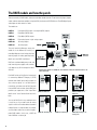
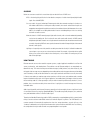
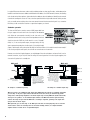
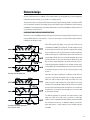
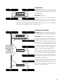
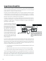
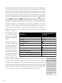
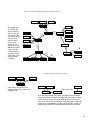
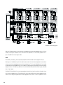
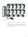
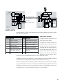
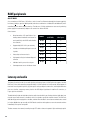
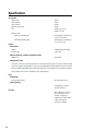
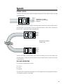
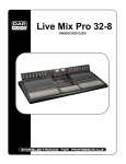
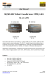
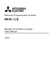
A D V A N C E D
S Y S T E M S
P R O D U C T S
ROUTING AUDIO VIA ETHERNET
Application Guide
Please note: This document, published in 1997, does
not incorporate the newer RAVE/s features, functions,
and specifications. However, it is still useful as a RAVE
overview and implementation guide.
Table of Contents
RAVE Digital Audio Router Application Guide
Routing: Getting audio from here to there and there, and there to over there … ............................. 3
One problem, three solutions ........................................................................................................................ 3
The RAVE models and how they work .......................................................................................................... 6
Glossary .......................................................................................................................................................... 7
How it works .................................................................................................................................................. 7
Network design .................................................................................................................................................. 9
Hardware and medium considerations ......................................................................................................... 9
Network topology examples ......................................................................................................................... 10
Two nodes with a direct cable connection ................................................................................................. 10
Two nodes with a 100baseTX hub .............................................................................................................. 10
Star topology ............................................................................................................................................... 11
Distributed star topology ............................................................................................................................. 11
Longer distance through fiber ...................................................................................................................... 12
Network limitations ..................................................................................................................................... 13
And the exceptions to the rules … ............................................................................................................. 16
Sample applications ....................................................................................................................................... 16
Stadium ........................................................................................................................................................ 16
Airport terminal ........................................................................................................................................... 18
Convention center ........................................................................................................................................ 19
Broadcast facility upgrade .......................................................................................................................... 22
RAVE peripherals ............................................................................................................................................. 23
QSC FE hubs ................................................................................................................................................. 23
Latency and audio ........................................................................................................................................... 24
Sound in free space ..................................................................................................................................... 25
Synchronization with video ......................................................................................................................... 25
Specifications .................................................................................................................................................. 26
Appendix ............................................................................................................................................................ 27
Address & Telephone Information ............................................................................................................... 28
©Copyright 1997, 1998 QSC Audio Products, Inc. All rights reserved.
“QSC” and the QSC logo are registered with the U.S. Patent and Trademark Office.
RAVE™ is a trademark of QSC Audio Products, Inc. CobraNet™ is a trademark of Peak Audio, Inc.
1
Edition 2.1, November 1998
2
RAVE Application Guide
Unless you’re working with a very small sound system, at some point you’ll probably have to deal with routing
audio signals, that is, getting audio from someplace to someplace else in real time, typically via wires. There
are several ways to do this, and the cost, reliability, performance, and ease of use will be greatly affected by
the method you use.
The latest (and we think, greatest) way to route audio is digitally, over a 100 megabit-per-second network, using
RAVE digital audio routers from QSC Audio. This applications guide will help you decide where and when to use
a RAVE network, and how to design it.
Routing: Getting audio from here to there and there,
and there to over there …
There are a number ways of getting multiple audio signals from one place to another. The simplest way from
Point A to Point B is by direct wire, as long as the distance is reasonable and there’s no need to quickly change
the routing. Examples of this include a multi-channel snake, or perhaps a small group of audio channels sent
via individual cables through a wall from one room to an adjacent room.
The solution gets more complex as you add more sources, destinations, or both, particularly if you need to keep
a high degree of flexibility in the configuration. In fact, a system using the direct wire method can grow
geometrically as the number of sources, destinations, or channels increase.
ONE PROBLEM, THREE SOLUTIONS
STUDIO
#1
8
pairs
send
8 pairs
send
+ +
8 pairs
return
8
pairs
return, × 28
To illustrate this phenomenon of increasing complexity, let’s look
at a theoretical but admittedly far-fetched job (hey, those “a train
STUDIO
#8
STUDIO
#2
bound for Philadelphia leaves New York traveling 70 miles per
hour” math problems in school had only a loose connection to
reality, too, but they taught you the concept): let’s say you had
a site with eight audio facilities—production studios, equipment
rooms, control rooms, whatever—and each one had to be able
STUDIO
#3
STUDIO
#7
to send and receive eight channels of audio to and from any of
the other facilities.
Point-to-point
This diagram shows the basket-like complexity of a point-toSTUDIO
#4
STUDIO
#6
STUDIO
#5
point direct-wire solution to the problem. There are 16 shielded
pairs of audio cables between every possible pair of rooms, and
there are 28 possible combinations of rooms—a total of 448
individual cables. Imagine the labor involved to pull that many
When routing many channels among many sources and destinations, direct point-to-point wiring is needlessly complex and costly.
3
cables and connect them to patch bays in each location. Imagine
STUDIO
#1
the likelihood of wiring errors and ground loops, and the susceptibility to EMI. On top of that, each room would require eight
STUDIO
#8
distribution amps. Hopefully, you’ll never need to move or re-
STUDIO
#2
arrange anything. It’s an unnecessarily complicated, difficult,
and expensive way to go.
8 pairs send × 8
8 pairs return × 8
Router control lines × 8
Crosspoint routing
Another solution is the crosspoint router. It takes the eight STUDIO
channels of audio from each room to a central switching box and
STUDIO
#3
64 × 64
Crosspoint Router
#7
distributes them to whichever other rooms request the audio.
The wiring complexity is much more manageable than with the
direct-wire technique, but there are still 128 shielded pairs to
connect, plus eight sets of control lines. And there is still the risk
STUDIO
#4
STUDIO
#6
of ground loops and EMI.
STUDIO
#5
Digital routing, using RAVE
Crosspoint routing is a better solution than pointto-point, but it still has its drawbacks
The third solution is using RAVE digital audio routers, which use
a 100baseTX Fast Ethernet medium to transport as many as 64
STUDIO
#1
channels of audio over singular CAT5 unshielded twisted pair
(UTP) network cable. Unlike the direct-wire approach, wiring
STUDIO
#8
needs in a RAVE system vary more or less directly with the
STUDIO
#2
number of locations you’re routing audio to and from. In the
One RAVE 188
in each studio
system shown here, there are eight rooms, so there are eight
wires, each connected to a RAVE 188, which sends eight
channels and receives eight channels. Add a room? Add a wire
and a RAVE unit. Run out of ports on the hub? Add another hub. STUDIO
Very simple.
STUDIO
#3
8-port 100baseTX hub
#7
100baseTX
CAT5 UTP cable × 8
Unlike the crosspoint router, the RAVE system is not centralized.
All audio channels are available anywhere anytime on the RAVE
network. The hub merely distributes the audio data among all the
RAVE units.
An additional benefit is that the RAVE network distributes audio
in the digital domain (48 kHz sample rate, 20 bits uncompressed)
STUDIO
#4
STUDIO
#6
STUDIO
#5
and is thus free from ground loops, and it enjoys a high immunity
to noise and EMI. Certain RAVE models have AES3-format (AES/
EBU) digital audio inputs and/or outputs, so you can route audio
freely among analog and digital devices without interim conversion.
4
A RAVE digital audio routing network uses a central hub and
reduces wiring requirements down to just a single network cable
to each location.
In review, here are the three routing solutions we’ve looked at.
DIRECT WIRE
Complexity: For all but the simplest, Point A-to-Point B situations, terrible
Wiring material cost: High, and increases geometrically with added drops
Wiring labor cost: High, and also increases geometrically with added drops; high likelihood of errors
Reliability: Highly prone to ground loops and EMI
Ease of use: Difficult
Routing: Individual channels
Expandability: Not advisable
Distance: Depends on conditions; a practical limit might be a couple hundred feet, although longer
distances are possible with suitable precautions
CROSSPOINT ROUTER
Complexity: Reasonable
Wiring material cost: Moderate to high
Wiring labor cost: Moderate to high
Reliability: Susceptible to EMI; may be prone to ground loops; unlikely to have redundant capabilities
Ease of use: Good
Routing: Usually by individual or pairs of channels
Expandability: Possible, depending on the capacity of the router
Distance: Depends on conditions; a practical limit might be a couple hundred feet
RAVE DIGITAL AUDIO ROUTER
Complexity: Very simple
Wiring material cost: Very low; might even already be installed
Wiring labor cost: Very low
Reliability: Free of ground loops; highly immune to EMI; capable of redundant operation
Ease of use: Good
Routing: Blocks of 8 audio channels
Expandability: Easy; up to 64 transmitted audio channels, but can accommodate any number of
receiving devices
Distance: With CAT5 UTP cable, up to 100 meters (328 feet) between hub and RAVE unit; with
100baseFX optical fiber, up to 2 kilometers (1.24 miles) under certain conditions
5
The RAVE models and how they work
There are currently six RAVE models, and each one handles 16 audio channels. Three have analog inputs, outputs,
or both, and the other three are digital, using the AES3 (also known as AES/EBU) format. The AES3 digital inputs
and outputs are dual channel or stereo.
The models are:
RAVE 88
Four digital (AES3) inputs + four digital (AES3) outputs
RAVE 81
Eight digital (AES3) inputs
RAVE 80
Eight digital (AES3) outputs
RAVE 188
Eight analog inputs + eight analog outputs
RAVE 160
16 analog outputs
RAVE 161
16 analog inputs
The main functional differences among the
models lie in the different I/O sections, as
these block diagrams show. Analog units have
internal jumpers for setting operating levels;
details are in the RAVE User Manual.
RAVE units use detachable power cords, and
their internal power supplies will automatically adapt to any AC line voltage from 90 to
240 volts.
Internal block diagram of a RAVE unit; chief difference among the different models is the
audio I/O (below)
Each RAVE unit has an RJ-45 jack on its rear panel
for connecting 100baseTX Category 5 (CAT5)
network cable. Audio inputs and/or outputs are
also on the rear panel, as is an RS232 port for
transmitting serial data over the RAVE network
from one RAVE unit to another. A pair of BNC jacks
provide a sync output and a “slave” input. More
RAVE 80: 8 AES3 outs
RAVE 81: 8 AES3 ins
RAVE 88: 4 AES3 ins + 4
AES3 outs
RAVE 160: 16 analog outs
RAVE 161: 16 analog ins
RAVE 188: 8 analog ins + 8
analog outs
details on the “slave” feature follow later in this
book.
You can use RAVE units in any combination that
is useful to you. If you need to take 16 analog
signals in one location and send them elsewhere
to digital inputs on a tape recorder, for example,
you only need to make sure you have the appropriate RAVE models—in this case, a RAVE 161
and a RAVE 80—to do the job.
6
GLOSSARY
Below are some terms used in this manual that might not be familiar to all RAVE users.
AES3—A technological specification for inter-device conveyance of a dual-channel (stereo) digital audio
signal. Also called AES/EBU.
Crossover cable—A type of twisted-pair Ethernet patch cable, but somewhat analogous in function to a
null modem cable. Unlike a normal patch cable, however, the transmit and receive wire pairs are
swapped at one end, permitting a direct connection of two nodes without a hub in between. A crossover
cable is also suitable for cascading hubs that don’t have an available uplink port. It also has nothing
to do with an audio crossover.
Network channel—A RAVE network group of eight audio channels, with a channel number designated by
a switch on the sending unit. Don’t confuse this term with actual audio channels. A RAVE network
multiplexes eight audio channels onto a single network channel and routes the entire network channel
as a whole. A receiving RAVE unit set to a particular network channel will output all eight of the network
channel’s audio signals.
Uplink port—A special port on a hub, used for cascading to another hub. Usually it’s offered in tandem with
a normal port so you can use one or the other, but not both. For example, a 5-port hub with an uplink
allows you to connect to five nodes via the normal ports, or to four nodes via normal ports plus one
hub via the uplink port.
HOW IT WORKS
Ethernet networks are most often used for computer systems; a typical application would be in an office with
servers, workstations, and shared printers. These devices use the Ethernet medium in an unregulated, nondeterministic way. This means that they transmit data messages (called “packets”) only when necessary, and
the length of the messages may vary depending on the sending device and on the type and amount of data being
sent. Each device, or node, on the network that has a message to send waits until there is no traffic, then sends
it. If two or more nodes try to send messages at the same time, a collision occurs; each node then waits a random
length of time before trying again. In this type of application, reasonable latency (the length of time from when
the transmitting node has a message ready to send, to when the receiving node actually receives it) is not a
problem, since a second or two delay in the transmission of a print job or an e-mail message won’t have any
noticeable effect.
Audio signals (especially multi-channel), however, generally can’t tolerate a delay of even a significant fraction
of a second, or even worse, a varying, unpredictable delay. This would cause glitches, dropouts, noise, and other
nasty and undesirable artifacts in the final audio signal.
Therefore, the CobraNet™ technology used in a RAVE system employs a regulated, deterministic system of packet
timing to ensure consistent and reliable transmission without dropouts or glitches. The RAVE devices on a
common network will automatically negotiate the time slots among themselves; one unit will act as the
“conductor” and broadcast a clock signal over the network to synchronize all the other RAVE units. For efficiency,
the sample data from eight audio channels are grouped together in each packet.
7
In a typical Ethernet environment, nodes usually send data packets to other specific nodes, and the data packet
headers contain both the source address and the destination address. On a RAVE network, however, the sending
units broadcast their data packets, without destination addresses but with addresses identifying the network
channels the sending units are set to. Then, to receive a particular block of eight audio channels sent by another
unit, you would set the receiving unit to the same network channel that the transmitting unit is on, somewhat
like tuning a radio or television receiver to a particular frequency or channel.
Redundant operation
To slave one RAVE unit to another, connect a BNC jumper cable from
the sync output of the main unit to the slave input of the redundant
unit. Select the same network channel(s) on the slave unit as are
selected on the main unit. As long as the slave input detects the clock
signal from the main RAVE unit, it will remain in a sort of “standby”
mode, i.e., if it has analog audio outputs, the output relays will stay
open to prevent the production of audio signals; if it has digital audio
outputs, the bitstream will continue, but the audio information will be as if the audio channels were muted; if
it has analog or digital audio inputs, the unit will not transmit data on the network.
However, once the clock signal disappears, as would happen if the main unit detects an internal fault, loses its
network connection, or just fails, the slave unit will go into normal operation. If the clock signal reappears, the
slave unit will go back to its standby role.
Main unit
Main unit
RAVE160
RAVE161
RJ-45
Sync out
Hub
RJ-45
Hub
Sync out
8 audio outs
8 audio ins
BNC-BNC
coax cable
RJ-45
CAT5 UTP cable
8 audio ins
CAT5 UTP cable
Slave in
RAVE161
Spare unit
(set to same network channel
as the main unit)
BNC-BNC
coax cable
8 audio ins
8 audio ins
An example of a redundant input setup
The spare unit will not transmit
data on the network as long as it
receives a sync signal from the
main unit. If the main unit
malfunctions or loses its network
connection, its sync signal will
stop, it will stop transmitting data,
and the spare unit will take over
operation.
The spare unit's audio outputs
will stay muted as long as it
receives a sync signal from the
main unit. If the main unit
malfunctions or loses its network
connection, its sync signal will
stop, its outputs will mute, and
the spare unit's audio outputs
will activate.
RJ-45
Slave in
RAVE160
Spare unit
(set to same network channel
as the main unit)
8 audio outs
8 audio outs
An example of a redundant output setup
When you operate a pair of RAVE units with analog inputs (RAVE models 161 and 188) in a redundant configuration,
you can safely “Y” the pairs of inputs between the main unit and the slave unit as you would with any parallel
analog devices with high input impedances. The internal output relays in analog RAVE units (models 160 and 188)
allow you to also parallel or “Y” the individual output channels of the RAVE units with their particular backup
channels. The relays will open when the RAVE unit is in standby or inoperative, preventing active outputs from
trying to drive the inactive outputs.
With digital units, you can often safely “Y” the AES3 inputs if the units are located physically close to each other
and the actual Y cables are reasonably short. For even better reliability, however, use a digital distribution
amplifier instead of Y cables. Do not “Y” digital AES3 outputs.
8
8 audio outs
Network design
Because a RAVE network uses a 100baseTX Fast Ethernet medium, you would generally use the same approach
to designing the RAVE network as you would for a computer network.
There are several ways to configure a RAVE network, from very simple to relatively complex. The number of RAVE
units in the network, where they are located, and your future expansion plans will determine what net topology
would be best. The same techniques you would use in designing a conventional 100-Mbps Fast Ethernet will assist
you in designing a RAVE network.
HARDWARE AND MEDIUM CONSIDERATIONS
RAVE units can use unshielded twisted pair wiring, but it must be at least Category 5 quality. Anything less may
cause unreliable operation of the network, if it runs at all. Fortunately, most new Ethernet cable installations
in buildings use Category 5 cable.
Most RAVE networks will require one or more hubs, which must be
compatible with 100baseTX Fast Ethernet. The next chapter will show
how these hubs are used. A hub is primarily a repeater with multiple
ports; any data that comes into one ports gets simultaneously distributed to all the other ports. A RAVE network will not work with the more
common 10baseT hubs, which can only handle 10 megabits per second.
Fast Ethernet hubs also cost more than the lower-speed versions, but
like any other computer equipment, the performance-to-price ratio is
continually getting higher and higher. In fact, whatever you spec today,
you’ll probably find an even better deal next month or even next week.
At some point, though, you have to say this is what you need now, and
go with it.
Cascading hubs with uplink ports
Most hubs have a port for uplinking or cascading to another hub. So if
you have a six-port hub, for example, with all six ports connected to
RAVE units, and you need to add a couple more RAVE units to the
network, you don’t need to replace the original hub with one having
more ports. All you need to do is add another hub, connect it via an uplink
port to the other hub, and hook up the new RAVE units. If your hubs have
no uplink ports, you can do the same thing by using a crossover cable
to interconnect the hubs.
Fast Ethernet techniques for operating over longer distances (>100
meters from RAVE unit to hub), such as conversion to a fiber optic
medium, are also compatible with RAVE hardware, although the RAVE
units themselves connect only via 100baseTX cabling. As with hubs,
Cascading hubs without uplink ports,
using crossover cables
higher performance is always becoming more available and more
affordable.
9
Network topology examples
TWO NODES WITH A DIRECT CABLE
CONNECTION
Advantages: very low cost; very high reliability; simple to
implement
Disadvantages: limited to 100 meters (328 feet) total
network size; no expandability; uses non-standard wiring
of RJ-45 connectors on Ethernet crossover cable
The simplest and most direct RAVE network comprises two RAVE units connected by a single crossover cable.
This network has only one segment, so the 100-meter limit applies to the segment and thus to the entire network.
There are no hardware costs other than the RAVE units themselves and the cable for the interconnection. Also,
there are few potential failure points. However, there is no way to connect additional RAVE units without
resorting to adding a hub, and because a crossover cable isn’t yet a common off-the-shelf item, you might have
to wire it yourself.
TWO NODES WITH A 100baseTX HUB
Advantages: greater network size—up to 200 meters (656
feet); high reliability; readily expandable; uses standard
Ethernet patch cables
Disadvantages: higher cost
This network is similar to the previous one, but with a hub in between, breaking up the network into two segments
which can each be up to 100 meters long. Yes, there is the added expense of a hub, and the addition of a critical
active device affects the network reliability situation in a definite but extremely small way. But the network media
can be simple off-the-shelf patch cables, which are much easier to buy ready-made than crossover cables. You
can also easily expand the network by connecting additional nodes to the hub. Astute observers and those who
have read ahead in the manual will notice that this network configuration is really just a star topology with only
two nodes.
10
STAR TOPOLOGY
Advantages: greater network size—up to 200 meters (656
feet); high reliability; readily expandable; uses standard
Ethernet patch cables
Disadvantages: higher cost
Add nodes—i.e., RAVE units—to the previous net layout
and you have the classic star topology. This name comes
from the hub being at the center and the nodes radiating out from it like the points of a star. It doesn’t matter
if the nodes are actually right next to one another while the hub is in another room—it’s still a star topology.
You can connect as many RAVE units as there are ports on the hub.
DISTRIBUTED STAR TOPOLOGY
Advantages: greater network size (see text); high reliability; readily expandable; uses standard Ethernet patch cables
Disadvantages: higher cost than smaller topologies
What do you do when you have more RAVE units than
available hub ports? Add more hubs, of course. Most Fast
Ethernet hubs now are stackable, either through an uplink
port that lets you connect an additional hub to one already
Maximum span for
this system (e.g.,
furthest node-to-hub
+ hub-to-hub + hubto-hub +
hub-to-node): 400
meters (1312 feet)
in the network, or through a backplane connection. The
resulting network topology is called a distributed star,
because it is made up of interconnected multiple stars.
The example shown here uses three hubs, so the maximum
size of this particular CobraNet network would be 400
meters (1312 feet), allowing two 100-meter cable runs
among the three hubs, plus 100-meter cable runs from the
two outer hubs to their RAVE units.
You can expand the distances even further by daisy-chaining
more hubs and cable segments. There are technical and
practical limits to this strategy; see the section on network
limitations for further information.
11
Longer distance through fiber
Sometimes a network may need to span a long distance but there is no practical need for hubs distributed along
the way. The computer networking industry, on whom we’re already relying for an economical and rugged
transport medium, has an answer to this need also: fiber optics.
Data signals sent over optical fiber don’t degrade as much as they do over copper wiring, and they are immune
to induced interference from electromagnetic and RF sources, fluorescent lighting fixtures, etc. Consequently,
a Fast Ethernet fiber optic network segment (100baseFX) can be up to 2 kilometers (6560 feet, or 1.24 miles) long,
twenty times longer than what is possible with CAT-5 UTP copper wire.
Due largely to increased economies of scale, fiber optic cable pricing has become more economical in recent years,
so even 62.5 µm multimode fiber is no longer painfully more expensive than CAT-5 UTP. However, because of
the added cost of media conversion, it’s usually most cost-effective to use fiber only when distance or
electromagnetic conditions require it.
This illustration at right shows a simple 2-node
network similar to the “hubless” one decribed
before, except nearly all of the interconnecting UTP cable between the RAVE devices has
*
been replaced by a couple 100baseTX-to100baseFX converters and a length of fiber
optic cable. The fiber optic medium allows you
to increase the distance between the RAVE
units by 2 kilometers. Some hubs, including
certain QSC FE models, have both UTP and
fiber ports and can thus perform the media
*
*Although any one fiber segment can be up
to 2000 meters long, and any single UTP segment can be up to 100 meters long, it may be
necessary to impose shorter limits, in consideration of cumulative delays caused by
devices and cabling. See text for more information.
conversion themselves.
If you opt for the “hubless” topology shown in the illustration, beware of certain types of media converter that
don’t have a Fast Ethernet chipset for communication but instead “passively” convert electrical pulses to light
pulses and vice-versa. Such converters might not pass the network start-up transmissions that the RAVE units
and other Fast Ethernet hardware use to set up 100 Mbps communication, and the network will fail. If you
encounter such a problem, there are several solutions you can try:
1.
At one or both ends, insert a Fast Ethernet hub in the network between between the RAVE unit and
the media converter.
2.
Replace the media converters with ones that have true Fast Ethernet communication capability.
3.
Replace the media converters with media-converting hubs, such as some of the QSC FE models.
The other network topologies described earlier also can be upgraded with optical fiber. This can be done with
media conversion on individual network segments (opposite page, top) or by using fiber to interconnect hubs
(opposite page, center), or combinations thereof. You can further simplify the networks by using hubs that have
built-in media conversion capability, such as certain QSC FE models.
12
Standard Ethernet Patch Cables
Category 5 Unshielded Twisted Pair (UTP) Cable
< 100 meters (328 feet) per segment*
*Although any one fiber segment can be up to 2000 meters long, and any one UTP segment can
Using fiber on individual network segments
be up to 100 meters long, it may be necessary to impose shorter limits, in consideration of
cumulative delays caused by devices and cabling. See text for details.
Optical Fiber (×2)
62.5 µm multimode
< 2000 meters (6560 ft, or 1.24 mi)*
*Although any one fiber segment can be up to 2000 meters long,
and any single UTP segment can be up to 100 meters long, it may
be necessary to impose shorter limits, in consideration of
cumulative delays caused by devices and cabling. See text for
more information.
Using fiber to link distant hubs in a network
Bit periods
1 RAVE bit period (@ 100
NETWORK LIMITATIONS
million bits per second) =
There are more possible network configurations than can be shown in this or any book, and as long as they use no
10 nanoseconds
switches or routers but otherwise meet Fast Ethernet standards, they generally will work with RAVE units. Keep in
mind, though, that every hub, length of cabling, media converter, etc., delays the data passing through it by a small
amount, and adding these to the system adds to the total delay time. CobraNet has a certain advantage over
Maximum CobraNet
regular Fast Ethernet, however, in that its deterministic nature affords more tolerance of delay than unregulated, non-
span
deterministic network traffic can handle: a network span or diameter of up to 2560 bit periods (with Fast Ethernet,
2560 bit periods, or 25.6
microseconds
1 bit period = 10 nanoseconds), or 25.6 microseconds. Unless you are designing very large and complicated RAVE
networks, though, you’re very unlikely to reach these limits. For further guidance on designing large-scale
networks, consult the CobraNet network guidelines on Peak Audio’s web site: http://www.peakaudio.com.
13
As mentioned before, the maximum CAT-5 UTP cable length between two network devices—that is, between any
RAVE unit, hub, etc., and any other—is 100 meters, or 328 feet. You can cover longer distances by using optical
fiber, as mentioned earlier, or by running 100-meter lengths of UTP cable linked by Fast Ethernet hubs. The latter
solution is practical mainly if you need, or are likely to need, RAVE units at the intermediate points, and it is possible
only if you actually have power sources for all the Fast Ethernet hubs. Ultimately, the cumulative round-trip propagation
delays of all the cables (typically 1.112 bit periods/meter) and intervening hubs (Class I hub: <140 bit periods;
Class II hub: <92 bit periods; QSC FE hub: <46 bit periods) imposes a limit on how far you can carry this sort of
configuration. See the CobraNet network guidelines at the Peak Audio web site (cited above) for further guidance,
especially if you are designing a CobraNet network whose span approaches or even exceeds 1000 meters.
A fiber optic run of typical 62.5 µm multimode fiber can be up to 2 kilometers, or 6560 feet or 1.24 mile. Singlemode fiber, a much higher grade, offers better data pulse integrity but exhibits the same amount of delay as
multimode. Therefore, it is not bound to a 2 km limit, but you must still consider its effect on total delay.
Although a RAVE network has a capacity of 64 audio channels—i.e., eight network channels, each with eight
audio channels—there is no set
limit to the number of receivers
Component
Round trip propagation, in
bit periods
and cabling, the data delays will
Optical fiber (multi-mode)
1.000/meter
increase.
CAT-5 cable
1.112/meter
This table shows the propaga-
DTE receiver (RAVE unit)
< 100
Class I hub
< 140
Class II hub
< 92
media converters are shown here,
QSC FE hub
< 46
which should give you an idea of
Digi MIL-180 media converter
48
Canary CFT-2132 100baseFX/100baseTX media converter
124
Transition Networks E-100BTX-FRL-01 media converter
133
that a RAVE network will support,
except that as you add more hubs
tion delay in various devices and
media used in a CobraNet network. Three different types of
the wide range of performance
parameters even among devices
with similar functions. When calculating the maximum system
span, you must add up all the delays involved, in cabling, hubs, converters, and the RAVE units themselves.
If you exceed the maxi-
For example, a 100-meter length of CAT-5 cable means a delay of 111.2 bit periods, and a Class I hub will have mum network diameter,
up to 140 bit periods of propagation delay. A Class II hub has a better level of performance, so the delay is shorter. CobraNet communication
The maximum span of a CobraNet network is 2560 bit periods, and as long as the sum of the propagation delays
from any one RAVE device to any other RAVE device is less than that amount, the network will operate properly
(if all other conditions are satisfactory, such as individual segment lengths being within limits).
might not function reliably.
In extreme cases, the network will simply stop functioning; more often, though,
it will pass audio but also
have noticeable artifacts,
such as clicks.
14
That’s why this network, despite its apparent complexity, will work …
RAVE unit
RAVE unit
RAVE unit
00 m
Class I hub 1
RAVE unit
100
m
0m
10
Class I hub 100 m Class I hub
RAVE unit
m
100
RAVE unit
Class I hub
10
0m
RAVE unit
100 m
Class I hub
RAVE unit
RAVE unit
B
100 m RAVE unit
Class I hub
100
m
RAVE unit
RAVE unit
Class I hub
100 m
RAVE unit
RAVE unit
RAVE unit
m
100
The maximum span of
this network is from
device A to device B.
There are seven 100meter lengths of CAT-5
cable (111.2 bit periods
each) and six Class I
hubs (up to 140 bit
periods each) in
between, plus the
delay of the receiving
RAVE unit (up to 100 bit
periods) at the other
end. These add up to a
total of up to 1718.4 bit
periods, which is well
within the 2560-bitperiod limit.
RAVE unit
A
RAVE unit
… but these seemingly simple networks won’t.
RAVE unit
RAVE unit
100
m
Class I hub
RAVE unit
m
120
In this network, one of the CAT-5 cable
segments is 120 meters long, which exceeds
the 100-meter limit.
RAVE unit
RAVE unit
RAVE unit
5m
Class I hub
100 m
2500 m (optical fiber)
Media converter
5m
Media converter
In this network, the maximum span comprises two 5-meter runs and one 100-meter
run of CAT-5 cable (total of 120 meters, or 133.4 bit periods), a Class I hub (up to 140 bit
periods), two media converters (let’s say you bought the really nice ones, at 48 bit
periods each—total, 96 bit periods), 2500 meters of optical fiber (2500 bit periods), and
the delay in the receiving RAVE unit (up to 100 bit periods). This makes a total of up to
2969.4 bit periods, which well exceeds the 2560-bit-period limit and spells trouble.
15
AND THE EXCEPTION TO THE RULES …
There is an exception to the maximum network diameter rule, which assumes that all points on the RAVE network can
send and receive equally well—in other words, it allows bidirectional communication anywhere on the network. But
if unidirectional communication is acceptable, you can exceed the 2560 bit-period limit as long as you follow all
other distance rules (100 m for UTP segments, 2 km for multimode fiber, et al). For example, you could have a RAVE
161 or RAVE 81 in one location, run a short UTP cable to a Fast Ethernet media converter, run single-mode fiber to another
Fast Ethernet media converter, and then a UTP patch cable to a RAVE 160 or RAVE 80 in another place. In this
situation, the fiber link could be 3, 4, or 5 kilometers long, or perhaps even longer, depending on the media converters.
Actual limits of unidirectional RAVE network operation haven’t yet been determined. Because of the variables
involved, QSC cannot guarantee satisfactory operation beyond the 2560 bit-period limit. But if you wish to try
yourself, here are some tips that will increase your chances of success:
•
Keep it simple. The fewer network channels being transmitted, the less effect the delay will have on
operation and the better your chances the data will get through to its destination without problems.
•
If possible, construct and test the RAVE network before installation: hook up the RAVE units to the
hubs, media converters, cabling, and all other devices and media to be used, or their exact equivalents,
and check to see that it all operates properly. This can save you a lot of time troubleshooting and
configuring later.
Sample applications
The following sample application contrasts solutions using conventional analog techniques and using RAVE
digital audio routers. You’ll find that especially in the more complex
systems, using RAVE devices typically requires much less
cable, conduit, and labor cost.
STADIUM
Remote
equipment
room
Remote
equipment
room
The stadium in this example has a central
control room, two remote equipment
10
20
30
40
50
40
30
20
10
rooms located 1,000 feet from the control
10
20
30
40
50
40
30
20
10
room, and one equipment room 300 feet
from the control room. The distances
used here are the lengths of the cable
runs. The first solution uses conventional
analog technology. The first RAVE solution
(A) uses existing cable tray (possible because
the optical fiber is immune to crosstalk and RF
Control
room
interference), while the second RAVE solution (B) uses
new dedicated ¾-inch conduit.
16
Equipment
room
Stadium analog system
The analog solution
The analog design uses 4600 feet of 32-pair cables run between the control room and each equipment room in
2300 feet of 3-inch steel EMT conduit.
RAVE solution A
This solution uses existing cable tray, so the only conduit cost is 300 feet of ¾-inch conduit from the cable tray
to the equipment rooms. Cabling is 2300 feet of 4-strand multimode optical fiber.
RAVE solution B
Routed through 2300 feet of new ¾-inch conduit is 2300 feet of 4-strand multimode optical fiber.
PA-1
Stadium RAVE system
(solution A shown)
RAVE 160
(typ.)
PA-1
RAVE 160
(typ.)
PA-2
100baseT
hub with
fiber-optic
I/O
PA-3
PA-2
100baseT
hub with
fiber-optic
I/O
PA-n
Audio
processing
equipment
Analog audio
lines (typ.)
1
16
1
16
1
Equipment room 1
PA-1
RAVE 160
(typ.)
PA-3
PA-2
100baseT
hub with
fiber-optic
I/O
PA-n
Equipment room 2
PA-3
PA-n
Equipment room 3
RAVE 161
(typ.)
100baseT
hub with
fiber-optic
I/O
¾" conduit,
fiber optic cable
¾" conduit,
fiber optic cable
¾" conduit,
fiber optic cable
Cable raceway
16
1
16
Central control room
17
AIRPORT TERMINAL
The airport terminal in this example has a main equipment room which houses the signal processing equipment,
along with four remote equipment rooms 250 feet apart along the length of the terminal. Each of the remote
rooms serves four gate areas, and each gate area is served by four audio channels—two in, and two out. There
are a total of 16 gates.
The analog solution
The analog system uses 1½-inch conduit in a direct run from each remote equipment room to the main equipment
room, for a total of 2,500 feet. From each remote equipment room to each of the four gate areas it serves is a
150-foot run of ¾-inch conduit, a total of 2,400 feet. Audio cabling throughout is 16,400 feet of four-pair shielded
copper wire.
Remote equipment room 1
Remote equipment room 2
1½" conduit,
four 4-pr cables
1½" conduit,
four 4-pr cables
Electrical
pull-box
Gate area 1
Counter
/jetway
Gate area 2
Counter
/jetway
Central control room
¾" conduit,
one 4-pr cable
(typ.)
Counter
/jetway
¾" conduit,
one 4-pr cable
(typ.)
Counter
/jetway
¾" conduit,
one 4-pr cable
(typ.)
Counter
/jetway
¾" conduit,
one 4-pr cable
(typ.)
Counter
/jetway
¾" conduit,
one 4-pr cable
(typ.)
Counter
/jetway
Counter
/jetway
¾" conduit,
one 4-pr cable
(typ.)
Gate area 14
¾" conduit,
one 4-pr cable
(typ.)
Gate area 11
¾" conduit,
one 4-pr cable
(typ.)
¾" conduit,
one 4-pr cable
(typ.)
Gate area 13
Gate area 10
Gate area 7
¾" conduit,
one 4-pr cable
(typ.)
Electrical
pull-box
Gate area 9
Gate area 6
Gate area 3
Counter
/jetway
¾" conduit,
one 4-pr cable
(typ.)
Counter
/jetway
1½" conduit,
four 4-pr cables
Electrical
pull-box
Gate area 5
¾" conduit,
one 4-pr cable
(typ.)
Remote equipment room 4
1½" conduit,
four 4-pr cables
Electrical
pull-box
¾" conduit,
one 4-pr cable
(typ.)
Audio
processing
equipment
Remote equipment room 3
Counter
/jetway
¾" conduit,
one 4-pr cable
(typ.)
Gate area 15
¾" conduit,
one 4-pr cable
(typ.)
Counter
/jetway
Gate area 4
Gate area 8
Gate area 12
Gate area 16
Counter
/jetway
Counter
/jetway
Counter
/jetway
Counter
/jetway
¾" conduit,
one 4-pr cable
(typ.)
Airport analog system
The RAVE solution
A single ¾-inch conduit runs the length of the terminal to accommodate the fiber optic cable connecting the main
equipment room with all of the remote equipment rooms. Three-quarter-inch conduit runs 150 feet long from
the remote equipment rooms to the gate areas carry 4-pair copper wire, the same as in the analog design.
The total amount of ¾-inch conduit used is 3,400 feet. Also used are 2,500 feet of 4-strand multimode fiber and
2,400 feet of 4-pair cable.
18
100baseT hub
with fiberoptic I/O
Fiber optic cable
in ¾" conduit
Remote
equipt.
room 1
Rave 188
(typ.)
Analog audio
lines (typ.)
Audio
processing
equipment
1
16
16
1
16
1
16
Central control room
¾" conduit,
one 4-pr cable
(typ.)
100baseT
hub with
fiber-optic
I/O
Counter
/jetway
¾" conduit,
one 4-pr cable
(typ.)
¾" conduit,
one 4-pr cable
(typ.)
Counter
/jetway
¾" conduit,
one 4-pr cable
(typ.)
Counter
/jetway
¾" conduit,
one 4-pr cable
(typ.)
Counter
/jetway
Rave 188
(typ.)
100baseT hub
with fiberoptic I/O
¾" conduit,
one 4-pr cable
(typ.)
Counter
/jetway
¾" conduit,
one 4-pr cable
(typ.)
Counter
/jetway
¾" conduit,
one 4-pr cable
(typ.)
Counter
/jetway
Rave 188
(typ.)
¾" conduit,
one 4-pr cable
(typ.)
Counter
/jetway
¾" conduit,
one 4-pr cable
(typ.)
Gate area 14
¾" conduit,
one 4-pr cable
(typ.)
Gate area 11
¾" conduit,
one 4-pr cable
(typ.)
Remote
equipt.
room 4
Gate area 13
Gate area 10
Gate area 7
¾" conduit,
one 4-pr cable
(typ.)
Remote
equipt.
room 3
Gate area 9
Gate area 6
Gate area 3
Counter
/jetway
100baseT hub
with fiberoptic I/O
Gate area 5
Gate area 2
Counter
/jetway
Remote
equipt.
room 2
Rave 188
(typ.)
Gate area 1
RAVE 188
(typ.)
1
100baseT hub
with fiberoptic I/O
Counter
/jetway
¾" conduit,
one 4-pr cable
(typ.)
Gate area 15
¾" conduit,
one 4-pr cable
(typ.)
Counter
/jetway
Gate area 4
Gate area 8
Gate area 12
Gate area 16
Counter
/jetway
Counter
/jetway
Counter
/jetway
Counter
/jetway
¾" conduit,
one 4-pr cable
(typ.)
Airport RAVE system
CONVENTION CENTER
The convention center includes 40 meeting rooms, four ballrooms, and four exhibition halls. An equipment room
is centrally located between the north and south meeting room corridors.
There are eight meeting rooms 300 feet (conduit length) from the equipment room, eight rooms 500 feet from
the equipment room, 12 meeting rooms at 750 feet, and finally, another 12 rooms at 1000 feet from the equipment
room. Each meeting room has a panel with six microphone inputs, two line inputs, and two line outputs.
There are four exhibition halls; the two central ones each have two input/output panels, and the two end halls
have three panels each. Each panel includes 16 microphone inputs, four line inputs, and four line outputs.
Each of the four ballrooms has a panel which includes 12 microphone inputs, two line inputs, and two line outputs.
The analog solution
Meeting rooms: An eight-pair cable and a four-pair cable are run to a remote equipment closet from each of four
meeting rooms in a 100-foot-long 1½-inch conduit. A 3-inch conduit is run from each remote equipment closet
back to the equipment room. These conduits each carry 4 eight-pair and 4 four-pair cables.
Total materials: 5,750 feet of 3-inch conduit, 4,000 feet of 1¼-inch conduit, 27,400 feet of 8-pair shielded copper
cable, and 27,400 feet of 4-pair shielded copper.
Exhibition halls: Each panel is home run to the central equipment room, an average of 1000 feet in a 2½-inch
conduit. Total materials: 10,000 feet of 2½-inch conduit, plus 10,000 feet of 16-pair and 10,000 feet of 4-pair cable.
19
Convention center analog system
Ballrooms: Each ballroom has a 12-pair and a four-pair cable home run to the central equipment room in a 1½-inch
conduit, an average run of 500 feet each. Total materials are 2,000 feet of 1½-inch conduit, 4,000 feet of 12pair, and 4,000 feet of 4-pair copper cable.
RAVE
In the RAVE system design, the microphone preamplifiers will be located in remote equipment closets.
Meeting rooms: One 900-foot long ¾-inch conduit connects each of the north remote equipment closets and one
connects each of the south equipment closets for the meeting rooms. This is a total of 1800 feet of ¾-inch conduit
for the meeting rooms plus 4000 feet of 1½-inch conduit to connect the panels in the meeting rooms to the remote
equipment closets. Total cabling is 1,800 feet of 4-strand multimode fiber, 4,000 feet of 8-pair copper, and 4,000
feet of 4-pair copper.
Exhibit halls: Each exhibit hall has one remote equipment closet with each two closets daisy-chained to a home
run to the central equipment room. Each exhibit hall has one local panel (150 feet from remote equipment closet)
and one or two other panels (500 feet from remote equipment closet). There is a total of 2,000 feet of ¾-inch
20
Remote equipment closet 1
4-strand fiber optic cable
in ¾" conduit
(typ.)
Analog audio
lines (typ.)
1
16
1
16
Audio
processing
equipment
1
16
1
16
1
16
1
16
1
16
1
16
RAVE 161
(typ.)
100baseT
hub with
fiber optic
I/O
100baseT
hub with
fiber optic
I/O
100baseT
hub with
fiber optic
I/O
100baseT
hub with
fiber optic
I/O
Remote equipment closet 2
Remote equipment closet 3
Remote equipment closet 4
Remote equipment closet 5
100baseT
hub with
fiber optic
I/O
100baseT
hub with
fiber optic
I/O
100baseT
hub with
fiber optic
I/O
100baseT
hub with
fiber optic
I/O
100baseT
hub with
fiber optic
I/O
1½" conduit
one 8-pr cable
one 4-pr cable
(typ.)
Meeting
room 1
Meeting
room 3
Meeting
room 5
Meeting
room 7
Meeting
room 9
Meeting
room 11
Meeting
room 13
Meeting
room 15
Meeting
room 17
Meeting
room 19
Meeting
room 2
Meeting
room 4
Meeting
room 6
Meeting
room 8
Meeting
room 10
Meeting
room 12
Meeting
room 14
Meeting
room 16
Meeting
room 18
Meeting
room 20
Remote equipment closet 6
Remote equipment closet 7
Remote equipment closet 8
Remote equipment closet 9
Remote equipment closet 10
100baseT
hub with
fiber optic
I/O
100baseT
hub with
fiber optic
I/O
100baseT
hub with
fiber optic
I/O
100baseT
hub with
fiber optic
I/O
100baseT
hub with
fiber optic
I/O
Meeting
room 21
Meeting
room 23
Meeting
room 25
Meeting
room 27
Meeting
room 29
Meeting
room 31
Meeting
room 33
Meeting
room 35
Meeting
room 37
Meeting
room 39
Meeting
room 22
Meeting
room 24
Meeting
room 26
Meeting
room 28
Meeting
room 30
Meeting
room 32
Meeting
room 34
Meeting
room 36
Meeting
room 38
Meeting
room 40
Remote equipment closet 11
(exhibit hall)
100baseT
hub with
fiber optic
I/O
Remote equipment closet 12
(exhibit hall)
Panel 1
Panel 2
100baseT
hub with
fiber optic
I/O
Panel 4
Panel 3
Central control room
2½" conduit
one 16-pr cable
one 8-pr cable
(typ.)
Convention center RAVE system
1½" conduit
one 12-pr cable
one 4-pr cable
(typ.)
Remote equipment closet 13
(exhibit hall)
Panel 5
100baseT
hub with
fiber optic
I/O
Remote equipment closet 14
(exhibit hall)
Panel 6
Panel 7
100baseT
hub with
fiber optic
I/O
Panel 8
Panel 9
Panel 10
Ballroom equipment closet
100baseT
hub with
fiber optic
I/O
Panel A
Panel B
Panel C
Panel D
conduit, 2,900 feet of 2½-inch conduit, 2,000 feet of 4-strand fiber, 2,500 feet of 16-pair copper, and 2,500 feet
of 8-pair copper.
Ballrooms: There is a 500-foot home run of ¾-inch conduit from the ballroom remote equipment closet to the
central equipment room. Additionally, 600 feet of 1½-inch conduit (4 rooms at 150 feet each) connect between
the remote equipment closet and the ballroom panels. Cable requirements are 1,250 feet of 4-strand fiber, 400
feet of 12-pair copper, and 600 feet of 4-pair.
21
BROADCAST FACILITY UPGRADE
An FM radio station has a studio facility located next to a hill; to gain antenna height, the station takes advantage
of the hilltop’s extra 300 meters in elevation for its transmitter location. But the distance between the studio
and transmitter sites is slightly over a mile, making a studio-transmitter link (STL) necessary.
Currently, the studio’s stereo air signal goes into an Optimod and a peak limiter, then into the stereo generator,
where the composite audio is sent up to the transmitter site over an aging 950 MHz STL. Piggybacked onto
the composite audio is a subcarrier carrying the audio-frequency analog control signals from the
transmitter remote control. The FM carrier’s 67 kHz SCA subcarrier carries encoded
telemetering signals for logging of transmitter operation. The station’s satellite
downlink is located at the studio, but if it were atop the hill at the
transmitter, the reception would improve and additional satellites carrying new programming
would be “visible” to the dish.
STUDIO
2 km of multi-mode
dual optical fiber
The design goals
The station management and chief engineer wish to accomplish several goals in this upgrade:
1.
Replace the 950 MHz STL.
2.
Relocate the station’s satellite dish and receiver to the transmitter site to reduce shadowing by the
hill.
3.
Free up the station’s 67 kHz SCA subcarrier, currently used for transmitter telemetering, for other
service uses with revenue-generating potential.
4.
Improve overall performance and audio quality.
The RAVE solution
The solution they chose uses a RAVE network with a fiber optic link between the studio and the transmitter
building. The network will use a RAVE 188 in each building, providing line-level analog inputs and outputs, eight
of each. At the studio, a QSC FE 3/1 hub, with three 100baseTX (UTP) ports and one 100baseFX (fiber) port, will
convert the network media to fiber for the long hop to the transmitter building. Its extra ports will allow for the
station to expand its internal routing system using additional RAVE units. The communication on the network
will be bi-directional—not only will it carry the left and right audio channels, SCA audio, and the encoded-audio
control signals for the transmitter and satellite receiver from the studio building to the transmitter building, but
it will also carry stereo audio from the satellite receiver and the encoded-audio telemetering signal in the opposite
direction. Additionally, audio channel overcapacity allows the chief engineer to make use of two channels for
monitoring the audio going into the stereo generator for comparison with the off-air audio signal from the FM
modulation monitor.
22
TRANSMITTER
1
2
3
4
5
6
7
8
L
R
QSC
FE 5/1 hub
2 km of dual multi-mode optical fiber
spare optical fiber link
SCA audio
L
R
L
R
ENCODER
Satellite
receiver
remote
control
QSC
FE 2/2 hub
Audio monitor
Satellite
receiver
1
2
3
4
5
6
7
8
1
2
3
4
5
6
7
8
Audio
monitor point
L R
telemetering
L
R
Audio from satellite downlink
Stereo
generator
SCA gen.
DECODER
Transmitter
telemetering
Studio site
FM exciter & transmitter
Transmitter site
To sat.
Satellite receiver
receiver
controller
DECODER ENCODER
1
2
3
4
5
6
7
8
RAVE 188
Transmitter
remote
control
Optimod &
peak limiter
DECODER
L
R
RAVE 188
Production studio
Control
room
switcher
ENCODER
Air studio
Transmitter
remote
control &
metering
Using RAVE as a combined
multi-purpose STL and TSL
At the transmitter site, a QSC FE 2/2 hub, which features two UTP and two fiber ports, will allow for a backup
fiber cable to be installed later.
Studio ➤ transmitter
Transmitter ➤ studio
Audio channel allocations
Channel Description
Channel Description
The table at left shows the allocation of the
1
Air signal, left channel
1
Satellite downlink, left channel
RAVE network’s audio channels.
2
Air signal, right channel
2
Satellite downlink, right channel
The optical fiber is jacketed for outdoor use
3
Transmitter remote control signals
(encoded audio tones)
3
Audio monitor, left channel
4
Leased SCA audio channel
4
Audio monitor, right channel
Fortunately, fiber optic cabling is immune to
5
Satellite receiver remote control
signals (encoded audio tones)
5
Transmitter telemetering (encoded
audio tones)
the hum fields around the AC wires. To be
Unused
generator, which will feed the FM exciter
6–8
Unused
and will be strung on the utility poles that carry
the AC service up to the transmitter site.
6–8
relocated to the transmitter site is the stereo
directly. Also, the SCA generator will be
switched over from transmitter telemetering tones to a regular leased audio channel.
The present microwave STL has a THD spec of 0.7% at 100% modulation and an S/N ratio of 65 dB, so the superb
audio performance of the RAVE network eliminates one of the weaker links in the chain.
Although the transmitter site has an emergency generator that automatically starts up in event of an AC power
loss, the chief engineer plans to also use an off-the-shelf uninterruptible power supply. The UPS will power the
RAVE 188, hub, transmitter remote control, and satellite receiver so they are unaffected by the several seconds
of lag between the loss of AC power and when the generator is running and stable.
23
RAVE peripherals
QSC FE HUBS
As a convenience to RAVE users, QSC offers a series of seven Fast Ethernet hub models that feature especially
low latency (<0.46 µs; equal to <46 bit periods) and various combinations of 100baseTX and 100baseFX (multimode fiber) ports for built-in media conversion. The hubs are 1 RU high and feature an auto-sensing switching
power supply that automatically adapts to AC service from 100 to 240 VAC.
Other features:
•
Manufactured to QSC specifications by a
leading network hardware manufacturer to
MODEL
TX ports
(CAT5 UTP)
FX ports
(fiber optic)
work specifically with RAVE audio distribu-
FE 5/0
5
0
FE 8/0
8
0
FE 3/1
3
1
ing hubs
FE 5/1
5
1
•
Heavy-duty rack-mount chassis
FE 2/2
2
2
•
High-speed cooling fan for demanding envi-
FE 5/2
5
2
FE 2/4
2
4
tion networks
•
Supported by QSC’s full 3-year warranty
•
Includes a switchable uplink port for cascad-
ronments
•
Individual activity sensor for each port
•
Overtemperature sensor with buzzer alarm
Latency and audio
The latency (how long it takes for an audio signal to get from the input of a RAVE unit to the output of another
RAVE unit on the same network) or propagation delay of a RAVE network is 6.3 milliseconds. What happens in
that time? An analog audio signal has go go through an analog-to-digital converter first, and its digital data then
goes on to a buffer, a temporary memory location. An AES3 digital signal doesn’t need A-to-D conversion, so
it goes right into the buffer.
The buffer briefly holds the 20-bit data from the audio channel while it gets lined up with the 20-bit data from
the other seven audio channels in the block, which is assigned to a particular network channel. The RAVE unit
adds identifying and managing bits to the data, and then when the block’s turn to be transmitted comes around
(as it does 48,000 times per second), the RAVE device sends the whole packet out onto the network and then
immediately lines up the next packet.
The data traverses the network, traveling through UTP cable at almost the speed of light and through optical
24
fiber at even closer to the speed of light. Hubs and other intermediate devices have their own propagation delay
and slow the data down by no more than one or two microseconds.
The receiving RAVE unit, when it sees a data packet with the identifier of the network channel it is set to, pulls
that packet into its buffer, separates the data into all eight audio channels, and feeds the data directly to the
outputs, if it’s a digital unit, or to digital-to-analog converters if it’s an analog one. And it does this 48,000 times
per second also.
All this happens in 6.3 milliseconds. You might look at the latency specification and wonder how it will affect your
system. It’s a perfectly legitimate question. To determine this, let’s first look at what the time interval equates to.
SOUND IN FREE SPACE
At an ambient temperature of 20° C (68° F), sound travels at a velocity of approximately 343 meters (1125 feet)
per second, or 34.3 cm (13.5 in) per millisecond. Therefore, the delay inherent in a RAVE network is equal to the
time it takes sound to travel 2.16 meters (7 feet 1 inch). If you use a RAVE network in a system for sound
reinforcement, cinema sound, stadium/arena sound, etc., you might need to consider this delay when you design
and set up the system, especially if you use any of the same audio program, routed both via a RAVE system and
by direct wire, to cover any of the same acoustic space.
For example, a large concert sound system uses both a main speaker system for the near audience and a system
of speakers for the outer reaches of the audience, delayed 150 milliseconds so it will be coincident with the
sound from the main speakers. It uses a RAVE network to distribute sound to the delayed system, but not to the
main system. The system engineer, therefore, will set the delay units for the outer system at 143.7 milliseconds,
because the RAVE network itself has 6.3 milliseconds of delay.
SYNCHRONIZATION WITH VIDEO
When using audio and video together, it is vital that they stay synchronized with each other. Otherwise, the
embarassing effects of people’s voices not matching the motions of their mouths, or of sound effects not
coinciding with the visual clues of their events, could occur.
NTSC video uses 525 lines per frame at a frame rate of 29.97 Hz, so each line of video is 63.56 microseconds
long. PAL and SECAM video use 625 lines at a frame rate of 25 Hz, so each line is 64.0 microseconds long. Thus,
the delay caused by a RAVE network’s latency represents only 99.1 lines of NTSC video, or 98.4 lines of PAL or
SECAM video. These are respectively less than 1/5 and 1/6 of a frame, and therefore will not cause noticeable
loss of synchronization between the visual and the audio programming.
25
Specifications
Analog Audio
Sample rate
A/D converters
D/A converters
Network transmission
THD
Signal to noise
RAVE 161 and 188 inputs:
RAVE 160 and 188 outputs:
48 kHz
20 bits
20 bits
20 bits
0.007% worst case,
0.004% @ 1 kHz
104 dB typical; 102 dB worst
case, 22 Hz–22 kHz
102 dB typical; 101 dB worst
case, 22 Hz–22 kHz
Network
Data Format
Header
Packet trailer
Standard Ethernet header
4 byte CRC.
Network Capacity (without unregulated traffic)
100baseTX
64 channels
Unregulated Traffic
To maintain continuous maximum performance, we recommend that you do not share the RAVE network
with other computer network devices. Gaps are inserted between each data packet to make the network
robust to limited unregulated traffic. Recurring management traffic should not seriously affect the network.
Large computer file transfers would likely cause audio dropouts.
Delay
Group Delay
Delay through network
6.3 milliseconds or less
Delay Variation
Guaranteed ±¼ sample
periods (±5.28 µs)
AC Power
90 to 264 VAC, 47 to 63 Hz.
No user selection of line
voltage or frequency is
required; the internal power
supply automatically
switches accordingly.
26
Appendix
ETHERNET CABLING
This diagram shows the pinout for standard unshielded twisted-pair (UTP) network cable. Both ends of the cable
are wired identically.
1 Tx +
2 Tx –
3 Rx +
4 not used
5 not used
6 Rx –
7 not used
8 not used
White/orange
Orange
White/green
Blue
White/blue
Green
White/brown
Brown
RJ-45 pinout for a standard
Ethernet patch cable (both ends
indentical)
A crossover cable has the RX and TX wire pairs switched around at one end. There are only two likely situations
that would require a crossover cable: to connect two RAVE devices directly, without a hub or other device in
between; and to cascade hubs that don’t have uplink ports.
1
2
3
4
5
6
7
8
White/orange
Orange
White/green
Blue
White/blue
Green
White/brown
Brown
RJ-45 pinout for an Ethernet
crossover cable
1
2
3
4
5
6
7
8
White/green
Green
White/orange
Blue
White/blue
Orange
White/brown
Brown
The wire in UTP cabling is twisted together in pairs. Rather than randomly choosing a wiring scheme for the
networking cable, it is important to have the RX wires in one pair and the TX wires in another pair, especially
in longer cable runs.
RS232 PORT INFORMATION
Pin assignments of 9-pid female D connector:
Pin 2: TX out
Pin 3: RX in
Pin 5: Ground
Pins 1 (DCD), 4 (DSR), and 6 (DTR) are tied together. Pins 7 (RTS) and 8 (CTS) are also tied together. DCE (receives
on TD) operation; parity bit not transported.
27
Address & Telephone Information
Address:
QSC Audio Products, Inc.
1675 MacArthur Boulevard
Costa Mesa, CA 92626-1468 USA
Telephone Numbers:
Main Number
(714) 754-6175
Sales Direct Line
(714) 957-7100
Sales & Marketing
(800) 854-4079
(toll-free in U.S.A. only)
Technical Services (714) 957-7150
(800) 772-2834
(toll-free in U.S.A. only)
Facsimile Numbers:
Sales & Marketing FAX
(714) 754-6174
Technical Services FAX
(714) 754-6173
BBS/World Group:
QSC OnLine Technical Support
1200-14400 bps; 8N1
(714) 668-7567
(800) 856-6003
CompuServe
GO QSCAUDIO
ID: 76702,2635
World Wide Web
http://www.qscaudio.com
28
www.qscaudio.com
1675 MacArthur Boulevard, Costa Mesa, CA 92626 USA • Ph: 714/754-6175
”QSC” and the QSC logo are registered with the U.S. Patent and Trademark Office.
© QSC Audio Products, Inc.