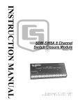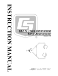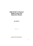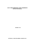
1
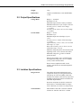
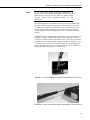
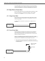
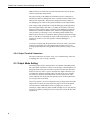
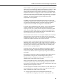
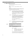
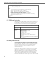
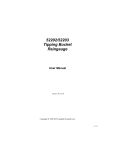
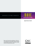
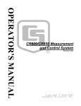
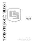
SDM-CVO4 4-Channel
Current/Voltage Output Module
Revision: 7/11
C o p y r i g h t © 2 0 0 1 - 2 0 1 1
C a m p b e l l S c i e n t i f i c , I n c .
Warranty and Assistance
PRODUCTS MANUFACTURED BY CAMPBELL SCIENTIFIC, INC. are
warranted by Campbell Scientific, Inc. (“Campbell”) to be free from defects in
materials and workmanship under normal use and service for twelve (12) months
from date of shipment unless otherwise specified on the corresponding Campbell
invoice. Batteries, fine-wire thermocouples, desiccant, and other consumables have
no warranty. Campbell's obligation under this warranty is limited to repairing or
replacing (at Campbell's option) defective products, which shall be the sole and
exclusive remedy under this warranty. The customer shall assume all costs of
removing, reinstalling, and shipping defective products to Campbell. Campbell
will return such products by surface carrier prepaid within the continental United
States of America. To all other locations, Campbell will return such products best
way CIP (Port of Entry) INCOTERM® 2010, prepaid. This warranty shall not
apply to any Campbell products which have been subjected to modification,
misuse, neglect, improper service, accidents of nature, or shipping damage. This
warranty is in lieu of all other warranties, expressed or implied. The warranty for
installation services performed by Campbell such as programming to customer
specifications, electrical connections to products manufactured by Campbell, and
product specific training, is part of Campbell’s product warranty. CAMPBELL
EXPRESSLY DISCLAIMS AND EXCLUDES ANY IMPLIED WARRANTIES
OF MERCHANTABILITY OR FITNESS FOR A PARTICULAR PURPOSE.
Campbell is not liable for any special, indirect, incidental, and/or consequential
damages.
Products may not be returned without prior authorization. The following contact
information is for US and International customers residing in countries served by
Campbell Scientific, Inc. directly. Affiliate companies handle repairs for customers
within their territories. Please visit www.campbellsci.com to determine which
Campbell Scientific company serves your country.
To obtain a Returned Materials Authorization (RMA), contact Campbell Scientific,
Inc., phone (435) 753-2342. After an applications engineer determines the nature
of the problem, an RMA number will be issued. Please write this number clearly
on the outside of the shipping container. Campbell Scientific's shipping address is:
CAMPBELL SCIENTIFIC, INC.
RMA#_____
815 West 1800 North
Logan, Utah 84321-1784
For all returns, the customer must fill out a “Declaration of Hazardous Material and
Decontamination” form and comply with the requirements specified in it. The form
is available from our website at www.campbellsci.com/repair. A completed form
must be either emailed to [email protected] or faxed to 435-750-9579.
Campbell Scientific will not process any returns until we receive this form. If the
form is not received within three days of product receipt or is incomplete, the
product will be returned to the customer at the customer’s expense. Campbell
Scientific reserves the right to refuse service on products that were exposed to
contaminants that may cause health or safety concerns for our employees.
SDM-CVO4 Table of Contents
PDF viewers note: These page numbers refer to the printed version of this document. Use
the Adobe Acrobat® bookmarks tab for links to specific sections.
1. Introduction..................................................................1
2. Specifications ..............................................................2
2.1 General Specifications ..............................................................................2
2.2 Output Specifications................................................................................3
2.3 Isolation Specifications.............................................................................3
3. Power Considerations.................................................4
4. Installation....................................................................4
4.1 Connection to a Datalogger ......................................................................4
4.2 Output Device Connections......................................................................6
4.2.1 Voltage Output Mode .....................................................................6
4.2.2 Current Output Mode......................................................................6
4.2.3 Shield and Ground Connections .....................................................7
4.2.4 Output Terminal Connectors...........................................................8
4.3 Output Mode Setting ................................................................................8
4.4 SDM Address Setting ...............................................................................9
4.5 Safety Considerations .............................................................................10
5. General Principles of Use .........................................12
5.1 Voltage or Current Signaling..................................................................12
5.2 Providing Excitation Supplies to Sensors...............................................12
6. Datalogger Programming..........................................13
6.1
6.2
6.3
6.4
6.5
CRBasic SDMCVO4 Instruction............................................................14
SDMCVO4 Instruction Example............................................................15
SDMSpeed Instruction ...........................................................................16
Edlog Instruction 103 .............................................................................16
Edlog Program Examples .......................................................................18
6.5.1 Voltage and 0-20 mA Current Output Modes...............................18
6.5.2 Restricted Range Current Output Modes (4-20 mA) ....................20
6.5.3 Providing Isolated Power Supplies to Sensors..............................22
Figures
1. SDM-CVO4................................................................................................1
4-1. Use of the Spring-Loaded Terminal Blocks (Top Position)....................5
4-2. Use of the Spring-Loaded Terminal Blocks (Front Position)..................5
4-3. Location of Jumpers on Circuit Board ....................................................9
4-4. Address Selection Switch......................................................................10
i
SDM-CVO4 Table of Contents
Tables
4-1.
4-2.
6-1.
6-2.
Datalogger to SDM-CVO4 Connections ................................................ 4
Switch Position and Addresses............................................................. 10
Description of SDM Speed................................................................... 16
Description of Instruction 103.............................................................. 17
ii
SDM-CVO4 4-Channel Current/Voltage
Output Module
The SDM-CVO4 is a synchronously addressed datalogger peripheral designed to allow the
datalogger to output variable voltage or current signals under program control.
FIGURE 1. SDM-CVO4 (shown without mounting brackets)
1. Introduction
The SDM-CVO4 expands the analog output capability of Campbell Scientific
dataloggers. Each output can be set to 0-10V or 0-20mA by the datalogger.
The output can be scaled and limited to 4-20mA by the datalogger program if
required by the application.
Typical applications will include driving remote ‘current-loop’ display units,
re-transmitting measured values to industrial control systems which have
current or high voltage inputs, sending control signals to valve controllers and
providing excitation voltages or currents to external sensors.
Each output is isolated both from the datalogger and the other channels on the
CVO4, thereby avoiding ground loop problems that might otherwise occur.
In the current mode the output can either act as a 2-wire current controller,
where the loop is powered from a remote voltage source, or it can be used to
generate a 0-20 mA current source using a voltage output derived from its own
power supply.
1
SDM-CVO4 4-Channel Current/Voltage Output Module
The SDM-CVO4 is a synchronously addressed datalogger peripheral. The
datalogger’s SDM ports are used to address the SDM-CVO4 and send out data
that defines the desired voltage/current output of each of the four channels.
The output levels are set by four values stored in variables or successive input
locations in the datalogger. A total of up to sixteen SDM-CVO4s or other
SDM peripherals may be connected and addressed from the same three ‘SDM’
ports.
NOTE
For the CR7, CR10(X), CR23X, and 21X dataloggers Instruction
103 is used to control the SDM-CVO4. This was introduced in
August 1988 for controlling SDM-AO4 functions. (The SDMAO4 is an older voltage-output-only peripheral.) Dataloggers
purchased before this date may use a different instruction.
The SDMCVO4 instruction is used with the CR800, CR850,
CR1000, CR3000, and CR5000.
2. Specifications
2.1 General Specifications
Compatible dataloggers:
CR800, CR850, CR1000, CR3000, CR5000, and
CR7. Also compatible with many retired
dataloggers such as the CR10, 21X, and CR23X.
Operating voltage:
12 VDC nominal (8 V to 16 V)
Current drain at 12V DC: Typical active quiescent current 27 or 54 mA,
depending on operating mode (no load on output
ports). To estimate the total current, add the
quiescent current to the sum of all output currents
multiplied by 1.5.
E.g. if each port is at 10 mA output, the total =
54 + (1.5*4*10) = 114 mA. The device can be
shut down to <0.5 mA with all outputs off.
Maximum Total
SDM cable length:
2
600 ft (182 m) for the CR7; 20 ft (6 m) for other
dataloggers if the SDMSpeed Instruction is not
used. For our CR800, CR850, CR1000,
CR3000, and CR5000 dataloggers, cable lengths
longer than 20 ft may be acceptable if the
SDMSpeed instruction is used.
Operating temperature:
-25°C to +50°C standard (-40 to 80°C optional)
Size:
176 mm wide x 111 mm high x 24 mm deep.
234 mm wide x 111 mm high x 24 mm deep
when fitted with brackets for mounting in
enclosure, etc. Mounting brackets have two holes
at 203.2 mm (8") spacing for screw fixings.
SDM-CVO4 4-Channel Current/Voltage Output Module
Weight:
370 g
EMC Status:
Complies with EN55022-1:1998 and EN500821:1998
2.2 Output Specifications
Voltage Mode:
Current Mode:
Range: 0 – 10,000 mV
Resolution: 2.5 mV
Maximum Output Current: 30 mA per channel.
Minimum load current: 5 μA if output < 200 mV.
Accuracy (+23°C): ±0.02% of set voltage
+ (± 2.5 mV).
Accuracy (-25 to +50°C): ±0.13% of set voltage
+ (± 2.5 mV).
Range: 0 – 20 mA
Resolution: 5 μA
Minimum output current (leakage): 5 μA at
+50°C.
Accuracy (+23°C): ±0.02% of full scale range
+ (± 5 μA).
Typical Accuracy (-25° to +50°C): ±0.1% of full
scale range + (± 5 μA).
Worst Case Accuracy (-25° to +50°C): ±0.15%
of full scale range + (±5 μA).
Minimum voltage drop across the internal current
regulating circuit: 2.5 V at 20 mA current flow.
Maximum voltage into Id relative to channel
ground: 20 VDC.
When in current mode, the Vo terminal outputs
an unregulated voltage source at 15 V nominal
(±10%), 30 mA maximum load.
Please contact Campbell Scientific for the
accuracy specification on extended temperature
tested units.
2.3 Isolation Specifications
Design criteria:
The unit has an internal isolation barrier and
components rated to provide signal isolation for
transients up to 1500 VAC (RMS), 2500 VDC
nominal. The isolation is between any output and
the SDM-CVO4 ground connection and between
individual output channels.
Protection components are built-in, which will
break down in a controlled fashion at voltages
close to this limit (see section 4.5, Safety Issues).
Tested isolation:
Each channel of each unit is tested for isolation
resistance at 500 VDC. Pass level > 10 MΩ.
3
SDM-CVO4 4-Channel Current/Voltage Output Module
Maximum recommended
continuous operating voltage: 240 VAC RMS differential between an output
and datalogger ground - providing all issues
relating to local regulations for safe installation
and operation are followed (see section 4.5,
safety issues).
3. Power Considerations
The SDM-CVO4 power requirements are large compared to most Campbell
Scientific products, especially when driving significant loads. Care must be
taken to ensure that the power supply can cope with this higher demand.
Alkaline batteries are not recommended for long term applications.
The SDM-CVO4 has two internal power supplies, one for channels 1 and 2
and one for channels 3 and 4. It will only turn on the power supply for
channels 3 and 4 if sent an instruction that sets the output of those channels. If
channels 3 and 4 are not used the power consumption is approximately 20 mA
lower than when all outputs are used.
Where supported by the datalogger, and when the application allows it, the
SDM-CVO4 can be shut down to reduce its consumption to less than 0.5 mA.
In this state all outputs are switched off.
4. Installation
Prior to installing the device you need to set the output mode (current or
voltage) of each channel by positioning internal jumpers (see section 4.3). You
also need to set the SDM address of the module (see section 4.4) and
additionally consider any safety issues specific to the installation (see section
4.5).
4.1 Connection to a Datalogger
For datalogger connections, see Table 4-1, below.
TABLE 4-1. Datalogger to SDM-CVO4 Connections
Connection Order
SDM-CVO4
Datalogger
Function
First
12 V
12 V on datalogger or external supply
Power
or G
Second
or G
Common Ground
C1
SDM-C1 (CR3000, CR5000) or C1 (other dataloggers)
Data
C2
SDM-C2 (CR3000, CR5000) or C2 (other dataloggers)
Clock
C3
SDM-C3 (CR3000, CR5000) or C3 (other dataloggers)
Enable
Multiple SDM-CVO4s may be wired in parallel by connecting the SDM and
power connections from one SDM-CVO4 to the next.
4
SDM-CVO4 4-Channel Current/Voltage Output Module
NOTE
If the total cable length connecting SDM-CVO4s to
SDM-CVO4s, other SDMs and the datalogger exceeds 6 m, the
SDM baud rate may need to be reduced to ensure reliable
operation. Please contact Campbell Scientific for more
information.
The transient protection of the SDM-CVO4 relies on a low resistance path to
earth. Ensure that the ground return wire has as low a resistance as possible.
An additional G terminal is provided which can be connected directly to the
enclosure earth ground terminal to ensure this. Make sure the ground wire
from the SDM-CVO4 to the datalogger goes to its G terminal and not the AG
terminal.
The SDM-CVO4 uses spring-loaded terminal blocks for the connections to the
datalogger which provide quick, vibration resistant, connections. To attach
wires, insert a small screwdriver into either the top or front slot, as appropriate,
and push to open the terminal spring. Strip any insulation from the wire to give
7 to 9 mm bare wire. Push the wire into the opening, and, while holding it in
position, withdraw the screwdriver to release the spring. The wire will now be
firmly held in place. See Figures 4-1 and 4-2, below.
FIGURE 4-1. Use of the Spring-Loaded Terminal Blocks (Top Position)
FIGURE 4-2. Use of the Spring-Loaded Terminal Blocks (Front Position)
5
SDM-CVO4 4-Channel Current/Voltage Output Module
You cannot reliably insert more than one solid-core wire into one terminal
connector unless the wires are soldered or clamped together. When inserting
more than one stranded wire, twist the bare ends together before insertion.
4.2 Output Device Connections
For each output channel there are four terminals which are labeled Vo, Id plus
) connections per channel. The two ground
there are two ground (
terminals are internally connected; two are provided for convenience.
4.2.1 Voltage Output Mode
The Vo terminal is the output for either the preset voltage signal, when the
channel is set to operate in voltage mode or an unregulated 15 VDC power
source in current mode.
In voltage mode the connection to a remote device is a simple two wire
connection:
CVO4
+
Vo
Inputs
–
Remote Voltage Input
4.2.2 Current Output Mode
The Id terminal acts as the input for the current that is to be controlled. In
current output mode you arrange to sink current into the terminal with a
positive current flowing relative to the ground terminals. (In voltage output
mode this terminal has no function.)
There are several different possible connections in current mode. As each
channel is isolated and floating, the method of connection to a remote device is
flexible. There are two different ways of powering the loop current.
a)
The remote device powers the loop, where, depending on the ground
referencing requirements of that device, the connection can be as shown in
the diagrams below:
Remote Voltage
V+ Source +ve
+
Remote Current
Input
CVO4
Id
–
V-
6
SDM-CVO4 4-Channel Current/Voltage Output Module
or
CVO4
Id
V+
+
Remote Current
Input
V-
b) The SDM-CVO4 provides the voltage source to drive the loop. In this case
the only real option is:
+
CVO4
Vo
Remote Current
Input
Id
–
In both cases you need to consider whether the voltage supply is high enough
to allow the maximum current to flow (20 mA) through all of the series
resistances in the current loop. When considering this factor you need to allow
terminal of the
for a minimum 2.5 V drop between the Id and
SDM-CVO4. You need to add this value to the estimated drop of 20 mA
flowing through the total resistance of the cable in the ‘loop’ plus any voltage
drop in the remote device (normally the voltage drop across a fixed sense
resistor).
As a simple example, consider the situation where the SDM-CVO4 is
powering the loop (as in (b) above), then the supply voltage output from Vo is
13.5 (absolute minimum). If the remote device has a 250 ohms sense resistor
this will drop 5V at 20mA (using Ohm’s law), which in addition to the
SDM-CVO4's 2.5 V drop in the loop means the maximum allowable voltage
drop in the cable of the loop should be 13.5 - 5.0 - 2.5 = 6.0 V. At 20 mA
current flow, the loop could therefore have a maximum resistance of 300
ohms. Standard 24 AWG (7/0.2 mm) cable has a typical resistance of 85 ohms
per 1000 m. Allowing double this resistance to form a loop (there and back),
will mean the total cable length could be as long as 1700 m before the supply
voltage started to limit the current flowing.
4.2.3 Shield and Ground Connections
It is generally advisable to used shielded (screened) cable when connecting the
output to any remote system to reduce the chances of noise pickup. The shield
will only be effective if it is connected to a good ground reference point.
As a result of the isolation barrier in the SDM-CVO4, the ground terminals
associated with the output connector of each channel cannot be considered as
good ground reference points. Therefore it is advisable to make the connection
of the screen to a good ground point at the remote system rather than the
7
SDM-CVO4 4-Channel Current/Voltage Output Module
SDM-CVO4. Do not connect the screen at both ends of the cable as this may
result in a ground loop being formed.
The output circuitry of the SDM-CVO4 includes protective components to
minimize the chances of damage that can be caused by transients which can be
induced in the signal cable. The protection clamps the transient voltages to
non-damaging levels relative to the ground terminals on each output channel.
If the voltage of that ground point exceeds the datalogger ground potential by
more than approximately 2500 VDC, a secondary level protector will break
down to provide a path for energy to discharge to the datalogger ground. The
likelihood of secondary breakdown can be avoided, if required (perhaps for
safety reasons), by connecting a wire to the output ground terminals of the
SDM-CVO4 to provide a low impedance path to ground. In doing this, though,
there is a risk that you will nullify the effects of the isolation barrier, e.g. if the
ground you connect to is the same ground to which the datalogger is
connected.
You need to carefully study the ground connections of the entire system when
connecting a grounding wire to the output ground terminal, both to avoid
creating a ground loop/referencing problem and also possibly causing a safety
issue.
4.2.4 Output Terminal Connectors
The output connections use normal, 4-way, screw terminal fixings. These can
be unplugged for ease of wiring, if required.
4.3 Output Mode Setting
An internal jumper sets the output mode for each channel of the SDM-CVO4.
The output mode can either be voltage or current mode, as described above. To
change the mode setting, the case must be opened. To do this first disconnect
the device from any source or power, disconnect the output connections (you
can unplug the connectors) and then remove the four larger screws from the
face of the case which has the product name written. Lay the unit on a flat
surface and then, after taking anti-static precautions, lift off the top half of the
case to expose the circuit board.
Then refer to Figure 4-3 below to identify the block of jumpers that control the
output mode. To operate in current mode, the jumper relevant to the channel
concerned must be installed between the two jumper pins, as shown. If
operating in voltage mode, the jumper should not bridge any two pins, but may
be stored, if required, by fitting it to just one of the pins, leaving the other half
unconnected.
8
SDM-CVO4 4-Channel Current/Voltage Output Module
Select channel(s) by
fitting jumper (s)
between appropriate
terminals. (Current
mode only.) Jumper
shown fitted to
‘enable’ Channel 4.
Jumper shown fitted
in the unconnected
‘stored’ position.
FIGURE 4-3. Location of Jumpers on Circuit Board
CAUTION
Do not store the jumpers between any other pins in the
block as this may switch the module into a factory
calibration mode, which may result in abnormal operation
and change of output accuracy.
The jumper settings can be overridden by the datalogger program, if required,
using special commands. Please contact Campbell Scientific for details.
4.4 SDM Address Setting
Each SDM-CVO4 can have 1 of 16 addresses. The factory-set address is 00.
Table 4-2 shows switch position and the corresponding address. Figure 4-4
shows the position of the switch on the right-hand end of the casing. Note that
you will have to remove the right-hand mounting bracket to gain access to this
switch.
9
SDM-CVO4 4-Channel Current/Voltage Output Module
TABLE 4-2. Switch Position and
Addresses
Switch Setting
Base 4 Address
0
1
2
3
4
5
6
7
8
9
A
B
C
D
E
F
00
01
02
03
10
11
12
13
20
21
22
23
30
31
32
33
Use a screwdriver to select address
FIGURE 4-4. Address Selection Switch
The address switch has a hexadecimal setting position (0..F). Most datalogger
instructions require you to enter the address as a base 4 number. Please see
your datalogger manual for more details of the convention required.
4.5 Safety Considerations
Where the potential voltage difference between the datalogger and the
SDM-CVO4 outputs is considered to be non-hazardous (less than 50 V) then
the unit can be used as any other peripheral without undue concerns as to the
risks to safety of the user.
As with the datalogger, it is essential to ensure that the device has a good
connection to an earth grounding point to allow the safe discharge of any
transient voltages and also ensure proper screening of the device. The
SDM-CVO4 has two G terminals on the black connector which are used for
connections to the datalogger. One of these can be used to connect the device
directly to the earth ground point of the enclosure to ensure the lowest
resistance path to ground.
10
SDM-CVO4 4-Channel Current/Voltage Output Module
Where the SDM-CVO4 is going to be used in applications where the potential
difference between the datalogger and the output terminals exceeds 50 V RMS
AC, 74 VDC then careful consideration has to be taken to ensure safe
operation and compliance with local safety regulations. For such applications
Campbell Scientific does not supply the device as a stand-alone device which
will meet all safety requirements. The SDM-CVO4 is supplied as a component
for the user to install in a system that is, itself, designed to comply with such
regulations. The following guidance is given to help users meet the
requirements of such regulations.
The SDM-CVO4 is designed such that the internal safety barrier meets the
requirements of BS EN 61010-1 (similar to IEC 950). However, the method of
wire connection and earthing facilities prevents the unit being claimed as
compliant with such standards, when supplied as a stand-alone unit.
To meet the safety requirements of most countries, wires carrying hazardous
voltages, terminated in screw terminals must be housed in an enclosure
requiring a tool to open it, and the enclosure must have international symbols
on the outside warning of high voltages. An additional warning label, in the
local language, may be required stating that the source of hazardous voltage
must be turned off before the enclosure is opened.
The exact nature of the enclosure is covered by the standards, but an enclosure
designed to house electrical equipment will usually meet the requirements.
Campbell Scientific's ENC 12/14 or 16/18 enclosures meet these requirements
if fitted with a padlock and with the correct labels on the door.
It is also necessary to ensure that metal parts on the outside of the enclosure
that might come in contact with active high voltage circuits are connected to a
safety ground. The ground lug of Campbell Scientific enclosures is the main
issue for the above enclosures, but this would, in any case, normally be the
point of contact to a good ground point.
Cables that connect to the output of the SDM-CVO4 should have adequate
strain relief at the point of exit from the enclosure, and the cable and any
connectors used should be rated to a high enough voltage and assembled in a
safe fashion.
If possible, the external device which is operating at a high voltage relative to
ground should be configured with an earth leakage breaker system to
disconnect it from the voltage source in the event of a breakdown of the
insulation in the system causing a leak to ground.
With a system made to the above requirements the maximum recommended
continuous operating voltage between the datalogger and input is 240 VAC.
This value is derived from the voltage rating of the terminal blocks used and an
internal suppression capacitor (see below).
The unit is designed to withstand a transient flash test of 1500 V RMS AC, for
two seconds. However, you need to be aware of some aspects of the design
which can influence the results of such a test if made.
a)
To help suppress emissions of electromagnetic interference the
isolation barrier is bridged by a 1nF, class ‘Y’ safety capacitor. This
11
SDM-CVO4 4-Channel Current/Voltage Output Module
is rated to withstand a 2700V, 2 second flash test, but will fail if
exposed to voltages in excess of 240 V RMS for long periods.
b) To provide protection from transients and static for this capacitor and
the opto-isolation component that bridges the barrier, there is a spark
gap across the barrier that has a 2500 VDC nominal breakdown
voltage. If this device is at the low end of its tolerance band (±10%),
combined with the normal tolerance of flash test devices, then the
spark gap could fire during a 1500 VAC flash test, which may cause
an indication of failure. Testing at a slightly lower voltage will
confirm whether there is a true fault or not.
If you have any doubts about the safety of your installation please first seek
advice from your local safety advisor and then Campbell Scientific if you
require further technical details.
CAUTION
To ensure safe and correct operation, the SDM-CVO4
must be installed where there is no risk of water ingress or
condensation.
5. General Principles of Use
5.1 Voltage or Current Signaling
Where the SDM-CVO4 is being used to retransmit measured values from
sensors to remote displays or measurement systems, the datalogger program
would normally follow the process of taking measurements and writing the
measured values into input locations using the same principles as given in the
manuals for those sensors.
The measured values would then be scaled using the processing instructions of
the datalogger, using either Instructions 37 and 34 or Instruction 53 (if
available in your datalogger). Prior to scaling, or during the scaling
calculations, the values relating to the four channels of the SDM-CVO4 will
normally be written into four new sequential input locations, both to match the
required inputs for Instruction 103 and also to preserve the original
measurement values for other purposes.
Instruction 103 would then be executed at the same rate as the measurements
have been made, to transmit the settings to the SDM-CVO4 and cause the
outputs to be updated at the same rate. As the required output levels are held in
a digital form in the SDM-CVO4, there is little advantage in sending data more
frequently – the only benefit being that it would recover more quickly in the
event of a loss of power.
5.2 Providing Excitation Supplies to Sensors
As mentioned in the introduction to this manual, one application for this device
is to provide an excitation to a sensor or sensors that are to be measured by the
datalogger. This may be considered where a sensor requires a precise voltage
or current excitation which cannot be provided by the datalogger itself, or
perhaps where exciting the sensor from the datalogger or its power supply
would cause a common-mode measurement problem. An example of the latter
12
SDM-CVO4 4-Channel Current/Voltage Output Module
problem is where the sensor outputs are not within the common-mode voltage
that the datalogger will accept (±2.5 V for the CR10X).
Careful consideration should be made before using an SDM-CVO4 for such a
function. Not only is it a relatively expensive method, but it can also result in a
less accurate method of sensor measurement (compared to when the datalogger
excites the sensors directly) if the precision of the output is critical to the
sensor accuracy.
The reason for this is that direct datalogger excitation is a ratiometric
measurement whereby any drift in the excitation output of the datalogger is
compensated for. With the SDM-CVO4 as an excitation source, any drift in its
output accuracy, or of the logger measurement accuracy, can result in a
combination of those errors. It is worth investigating, therefore, the exact
requirements of the sensors you wish to use. For instance, on closer inspection
of the specification of many pressure sensors you will often find the
recommendation of 10V excitation, but in reality many will accept a lower
voltage. If new sensors are to be bought for a specific project, it can be worth
checking if versions of sensors are available that will accept a low voltage
excitation.
There are, however, some sensors that have active components or that have
large common mode output voltages that require an isolated and/or precise
high voltage supply within the current output capability of the SDM-CVO4. In
this context the SDM-CVO4 can be used to provide an isolated supply which
can be regulated in the range of 0-10,000 mV, a regulated current (0-20 mA)
or an unregulated 15 V (nominal) supply (by setting current output mode and
using the Vo terminal).
In these applications, if all channels of the SDM-CVO4 are being used for
exciting sensors, you can use the standby mode between measurements to save
power. To do this you would send a command (instruction 103 with zero reps see below) to the SDM-CVO4 to shut it down after making the measurements.
When using this mode you need to allow at least 100ms after turning the
SDM-CVO4 on again (by using instruction 103 with a non-zero number of
reps) for the outputs to stabilize, before starting your measurement sequence.
It is possible that you can power more than one sensor from each output of the
SDM-CVO4, either by parallel connection in voltage output mode or serial
connection in current output mode. Make sure, however, that you do not try to
take more current than available in voltage mode. Additionally you also need
to check that all outputs from the sensors powered by one channel do not have
a spread which exceeds the common mode range of the datalogger inputs.
6. Datalogger Programming
Our CR800, CR850, CR1000, CR3000, and CR5000 use the SDMCVO4
instruction in CRBasic. Our CR7, CR10(X), 21X, and CR23X dataloggers use
Edlog Instruction 103. Both CRBasic and Edlog are provided in PC400,
LoggerNet, and RTDAQ software.
13
SDM-CVO4 4-Channel Current/Voltage Output Module
6.1 CRBasic SDMCVO4 Instruction
This instruction is used to control the SDM-CVO4 four channel
current/voltage output device.
Syntax
SDMCVO4 ( CVO4Source, CVO4Reps, SDMAddress, CVO4Mode )
Remarks
This instruction controls the SDM-CVO4, which outputs a voltage or a current.
Internal jumpers are used to set the mode for the device, but the jumpers can be
overridden with the Mode parameter in this instruction.
CVO4Source
The CVO4Source parameter is a variable array that holds the
values for the voltages (millivolts) or currents (microamps)
that will be output by each channel of the device (Source(1)
sets channel1, Source(2) sets channel2, etc.). When outputting
a voltage, the variable must be within the range of 0 to 10,000.
When outputting a current, the variable must be within the
range of 0 to 20,000.
CVO4Reps
The CVO4Reps parameter indicates the number of channels to
set to the defined voltage or current. Additional SDM-CVO4
devices can be controlled by one SDMCVO4 instruction by
assigning them consecutive addresses and setting the
CVO4Reps parameter to a value equal to the total number of
channels of all devices (e.g., to set all four channels on two
devices, set the CVO4Reps parameter to 8).
If the CVO4Reps parameter is set to 0, power to the device
will be turned off.
SDMAddress
NOTE
The SDMAddress parameter defines the address of the SDMCVO4 which will be affected by this instruction. Valid SDM
addresses are 0 through 14. Address 15 is reserved for the
SDMTrigger instruction.
CRBasic dataloggers use base 10 when addressing SDM devices.
Edlog programmed dataloggers (e.g., CR10X, CR23X) used
base 4 for addressing.
CVO4Mode
The CVO4Mode determines what type of signal will be output
by the device. The options are:
Option
Description
0
1
10
11
Voltage output, use jumper settings (scale only)
Current output; use jumper settings (scale only)
Voltage output; override jumper setting
Current output; override jumper setting
The two override options (10 and 11) affect all of the channels
of all of the SDM-CVO4 devices being controlled by this
instruction. These two options override the hardware settings
14
SDM-CVO4 4-Channel Current/Voltage Output Module
in the device. Use of this mode takes approximately 2
milliseconds additional time per device. When either of these
options is used you lose the flexibility of setting the output
mode for each channel individually. Additionally, subsequent
programs sent to the datalogger must also use an override
mode or the power must be cycled on the device to return it to
its default state. Otherwise, if 0 or 1 is entered it will be
ignored and the device will remain in its last override state.
NOTE
Current output requires an external resistor from Id to +V.
6.2 SDMCVO4 Instruction Example
This program example is for a weather station measuring wind speed, wind
direction, temperature, and relative humidity. Each parameter is scaled to 0 to
10000 mVDC, and output to a SCADA system through the SDM-CVO4.
Public WS_ms
Public WD_0_360
Public Temp_C
Public RH
Public WD_0_540
Public Flag
Public CVO4Output(4)
Alias CVO4Output(1) = WSOut
Alias CVO4Output(2) = WDOut
Alias CVO4Output(3) = TempOut
Alias CVO4Output(4) = RHOut
'Code for DataTable OneMin
DataTable(OneMin,1,-1)
DataInterval(0,1,Min,0)
WindVector (1, WS_ms,WD_0_360, IEEE4, 0, 0, 0, 0)
Average(1,Temp_C,IEEE4,0)
Sample(1,RH, IEEE4)
EndTable
BeginProg
Scan(1,Sec,1,0)
' Code for 03001 wind measurements, WS_ms & WD_0_360:
PulseCount(WS_ms, 1, 1, 1, 1, 0.75, 0.2)
BrHalf(WD_0_360, 1,mV1000, 1, 1, 1, 1000, True, 1000, 250, 355, 0)
' Code for CS500 measurement, AirTC and RH:
VoltSE(Temp_C,1,mV1000,3,0, 0, _60Hz,0.1,-40.0)
VoltSE(RH,1,mV1000,2,0, 0, _60Hz,0.1, 0)
' Call Data Table
CallTable(OneMin)
' Convert 0-360 WD to 0-540:
If WD_0_540 >= 270 and WD_0_360 <180 Then
WD_0_540 = WD_0_360 + 360
15
SDM-CVO4 4-Channel Current/Voltage Output Module
Else
WD_0_540 = WD_0_360
EndIf
' Scale the measurements for the SDM-CVO4 to output 0-10000 mV
WSOut = WS_ms*200 'WS: 0-50 m/s = 0-10000 mV
WDOut = WD_0_540 *18.59 'WD: 0-540 deg = 0-10000mV
TempOut= 100*(Temp_C+40) 'Temp: -40-60 deg C = 0-10000 mV
RHOut = RH *100 'RH: 0-100 % RH = 0-10000 mV
' Send mV outputs to SDM-CVO4 using the option to override the switch settings
SDMCVO4 (CVO4Output(),4,0,10)
NextScan
EndProg
6.3 SDMSpeed Instruction
Changes the rate that a CR800, CR850, CR1000, CR3000, or CR5000 uses to
clock the SDM data. Slowing down the clock rate may be necessary when
long cables lengths are used to connect the datalogger and SDM devices.
TABLE 6-1. Description of SDM Speed
Parameter
& Data Type
BitPeriod
Constant or
variable
Enter
The time per bit, in microseconds.
Initial Setting (default): 26.04 µS
Resolution: 8.68 µS
Min Setting: 8.68 µS
Max Setting: 2.2 mS
SDMSpeed(30) gives: 26.04 µS
SDMSpeed(k) gives: bit_rate = INT((k*72)/625) *
Resolution
When calculating SDMSpeed(k), the loggers round down to
the next higher bit.
6.4 Edlog Instruction 103
To allow full backwards compatibility with older dataloggers and operating
systems, the SDM-CVO4 is designed to work with the instruction supplied to
control the SDM-AO4 – Instruction 103. However, most datalogger manuals
and program editor help systems do not refer to the SDM-CVO4 in the
description of Instruction 103. Please see the details of use below to
understand the differences.
Instruction 103 is described in Table 6-2 and allows you to set four separate
output levels for one SDM-CVO4, or several output levels with multiple
SDM-CVO4s. Output levels are reset each time Instruction 103 is executed.
Instruction 103 was originally designed to take an input location range of
-5000 to +5000 and output this directly in mV when using the SDM-A04.
When used with the SDM-CVO4, the same range of values (±5000) in an input
16
SDM-CVO4 4-Channel Current/Voltage Output Module
location is used to scale the output to 0-10000mV for voltage mode, or
0-20 mA for current output mode.
In most applications a specific range of a measured value is scaled to utilize the
full scale output of SDM-CVO4. For instance, a temperature sensor reading in
the range of -20°C to +50°C would be scaled so at -20C the output is 0 mV
and at +50°C the output is 10000 mV. To do this with the SDM-CVO4 you
would use the mathematical functions of the datalogger to calculate a scaled
value in a new input location, so that the value is -5000 when the temperature
is -20°C and +5000 at +50°C.
The datalogger limits the output of the SDM-CVO4 so that even if the
measured value exceeds the intended range (i.e. the scaling value exceeds
±5000) the signal output is limited to the equivalent output at -5000 or +5000.
Therefore the datalogger instruction does not normally need to have extra
instructions to limit the scaling value range. However for displays or input
devices which require a current signal of 4-20 mA, the datalogger program
needs to include extra instructions to prevent the scaling value going below
- 3000 (see the examples below) and thereby setting the lowest possible output
to 4 mA.
When checking the output of the SDM-CVO4 against the scaling value you
should be aware that the output changes in discrete steps, e.g. 2.5 mV in
voltage mode. When the datalogger works out which of these discrete steps to
set for a given scaling value, a combination of floating point mathematics
followed by truncation to an integer value is made. This will sometimes result
in the transition from one output step to the next not happening at the exact
midpoint value of each 2.5 mV step, although it should happen within a limit
of ±0.5 in terms of the scaling value stored in the input location.
The number of repetitions, parameter 1, specifies the total number of
SDM-CVO4 output channels to be set. The address of the first SDM-CVO4 is
specified with parameter 2; multiple SDM-CVO4s must have consecutive
addresses. Parameter 3 is the starting input location containing the scaling
value for the first output channel of the first SDM-CVO4. Subsequent scaling
values must be contained in consecutive input locations immediately after the
first input location specified in parameter 3.
For example, two SDM-CVO4s can be used to output eight signals, which are
contained in input locations 15 to 22. There are eight repetitions, and so eight
(8) is entered for parameter 1. The SDM-CVO4s must have consecutive
addresses (e.g. 31 and 32), and so parameter 2 would contain 31 in this case.
Fifteen (15) would be entered for parameter 3.
TABLE 6-2. Description of Instruction 103
Par.
Number
01:
02:
03:
Data
Type
2
2
4
Description
Reps — Number of analog outputs
Address of SDM-CVO4 in base 4 (00 to 33)
Input loc. holds scaling value for the output level
17
SDM-CVO4 4-Channel Current/Voltage Output Module
Setting the Reps parameter to 0 (Zero) will cause the addressed SDM-CVO4 to
shut down, turning off all its outputs. It will turn on channels 1 and 2 at the
next execution of Instruction P103 where the reps parameter is 1 or 2. If the
reps parameter is greater than 2, then all the channels will be turned on.
Refer to the manual for the datalogger being used for full details of the
execution time of Instruction 103. All of the outputs of the SDM-CVO4 will
change simultaneously approximately 10ms after the instruction is completed
by the datalogger, or 100ms after power-up.
If the SDM-CVO4 loses power for any reason, when power is restored the
outputs will return to the default ‘off’ state. This will be held until the
datalogger runs Instruction 103 again to update the output levels required.
6.5 Edlog Program Examples
The following Edlog program examples are given to help you understand the
general principles involved in the use of the SDM-CVO4.
6.5.1 Voltage and 0-20 mA Current Output Modes
This program example is for a simple weather station with a CR23X
Micrologger measuring wind speed, wind direction, temperature and solar
radiation. Each parameter is scaled to the full-scale output range of the
SDM-CVO4 which would be 0-10,000 mV DC or 0-20 mA, depending on the
output jumper settings. Programming for the CR10X is very similar.
; {CR23X}
; Example weather station program to show scaling values
; for the SDM-CVO4
*Table 1 Program
01: 1
Execution Interval (seconds)
; Measure the output from a switch closure anemometer (A100R)
1: Pulse (P3)
1: 1
2: 1
3: 22
4: 1
5: 1.25
6: 0.0
18
Reps
Pulse Channel 1
Switch Closure, Output Hz
Loc [ WindSpeed ]
Mult ; Scale to m/s
Offset
SDM-CVO4 4-Channel Current/Voltage Output Module
; Measure the wind direction from a potentiometer windvane
2: Excite-Delay (SE) (P4)
1: 1
Reps
2: 14
1000 mV, Fast Range
3: 1
SE Channel
4: 1
Excite all reps w/Exchan 1
5: 1
Delay (units 0.01 sec)
6: 1000
mV Excitation
7: 2
Loc [ WindDir ]
8: 0.357
Mult ; Scale to angle in degrees
9: 0.0
Offset
; Measure air temperature from a 107 probe
3: Temp (107) (P11)
1: 1
Reps
2: 2
SE Channel
3: 31
Excite all reps w/E1, 50Hz, 10ms delay
4: 3
Loc [ AirT
]
5: 1.0
Mult ; Scale to degrees C
6: 0.0
Offset
; Measure solar radiation from an SP-Lite
4: Volt (SE) (P1)
1: 1
Reps
2: 32
50 mV, 50 Hz Reject, Slow Range
3: 3
SE Channel
4: 4
Loc [ Radiation ]
5: 100
Mult
6: 0.0
Offset
; Now output data in the normal way to final storage
5: If time is (P92)
1: 0
Minutes (Seconds --) into a
2: 1
Interval (same units as above)
3: 10
Set Output Flag High (Flag 0)
6: Real Time (P77)
1: 110
Day,Hour/Minute (midnight = 0000)
7: Wind Vector (P69)
1: 1
Reps
2: 0
Samples per Sub-Interval
3: 0
S, é1, & å(é1) Polar
4: 1
Wind Speed/East Loc [ WindSpeed ]
5: 2
Wind Direction/North Loc [ WindDir ]
8: Average (P71)
1: 2
Reps
2: 3
Loc [ AirT
]
; Now the code to scale the values and update the SDM-CVO4
19
SDM-CVO4 4-Channel Current/Voltage Output Module
; As we have four channels to output, we will first copy the
; current readings with P54, block move, in a block of four
; input locations to hold the scaled outputs
9: Block Move (P54)
1: 4
No. of Values
2: 1
First Source Loc [ WindSpeed ]
3: 1
Source Step
4: 5
First Destination Loc [ ScldOut_1 ]
5: 1
Destination Step
; Then apply the scaling with one Instruction P53
; The readings are scaled -5000 to +5000, i.e. to
; cover the full scale range which would equate to
; 0 - 10,000 mV in voltage mode or 0-20 mA in
; current mode.
; Windspeed to cover the range 0-100 m/s
; Wind direction to cover 0-360 degrees
; Temperature -25 to +50 degrees C
; Radiation 0 - 1000 m^2/s
10: Scaling Array (A*Loc+B) (P53)
1: 5
Start Loc [ ScldOut_1 ]
2: 100
A1 ; WS multiplier
3: -5000
B1 ; WS Offset
4: 27.7778 A2
5: -5000
B2
6: 133.333 A3
7: -1666.67 B3
8: 10
A4
9: -5000
B4
; Now update the SDM-CVO4 with the information
; for the four channels
11: SDM-AO4 (P103)
1: 4
Reps
2: 30
SDM Address
3: 5
Loc [ ScldOut_1 ]
6.5.2 Restricted Range Current Output Modes (4-20 mA)
When driving a system that requires a restricted current range then the fullscale range is reduced accordingly. In the case of 4-20 mA devices the
maximum range is 8000 units and the minimum value should be scaled to
-3000 and prevented from going below this level.
The following partial program could be used in place of the last two
instructions in the example above.
20
SDM-CVO4 4-Channel Current/Voltage Output Module
; Then apply the scaling with one instruction P53
; The readings are scaled -3000 to +5000, i.e. to
; cover the range which would equate to
; 4-20 mA in current mode.
; Windspeed to cover the range 0-100 m/s
; Wind direction to cover 0-360 degrees
; Temperature -25 to +50 degrees C
; Radiation 0 - 1000 m^2/s
10: Scaling Array (A*Loc+B) (P53)
1: 5
Start Loc [ ScldOut_1 ]
2: 80
A1 ; WS multiplier
3: -3000
B1 ; WS Offset
4: 22.2222 A2
5: -3000
B2
6: 106.667 A3
7: -333.32 B3
8: 8
A4
9: -3000
B4
; Now limit the lowest scaled value to -3000 (4 mA)
; As we have four 4-20 mA current outputs, a loop
; construct is the easiest way to do this.
11: Beginning of Loop (P87)
1: 0000
Delay
2: 4
Loop Count
; If the scaled value is less the –3000
12: If (X<=>F) (P89)
1: 5
-- X Loc [ ScldOut_1 ]
2: 4
<
3: -3000
F
4: 30
Then Do
; then set the value to –3000
13: Z=F (P30)
1: -3000
2: 00
3: 5
F
Exponent of 10
-- Z Loc [ ScldOut_1 ]
14: End (P95)
15: End (P95)
21
SDM-CVO4 4-Channel Current/Voltage Output Module
; Now update the SDM-CVO4 with the information
; for the four channels
16: SDM-AO4 (P103)
1: 4
Reps
2: 30
SDM Address
3: 5
Loc [ ScldOut_1 ]
6.5.3 Providing Isolated Power Supplies to Sensors
This program example sets all the outputs of the SDM-CVO4 to 10 V to
provide isolated power supplies to four separate sensors. The program includes
code to put the SDM-CVO4 into standby mode after the measurements are
made.
; {CR10X}
; An example program which show use of the SDM-CVO4
; as an isolated power supply for 4 sensors requiring
; 10 V drive and producing 0-100 mV signals.
; This shows how to set the SDM-CVO4 into standby mode.
*Table 1 Program
01:
60
Execution Interval (seconds)
; Store a fixed value of 5000 = 10 V output
; in the four scaling locations
1: Bulk Load (P65)
1: 5000
F
2: 5000
F
3: 5000
F
4: 5000
F
5: 0.0
F
6: 0.0
F
7: 0.0
F
8: 0.0
F
9: 1
Loc [ Scale_1 ]
; Tell the SDM-CVO4 to set all four outputs to 10,000 mV
; The SDM-CVO4 address is zero in this example.
; This will cause the SDM-CVO4 to come out of standby
; mode.
2: SDM-AO4 (P103)
1: 4
Reps
2: 00
SDM Address
3: 1
Loc [ Scale_1 ]
22
SDM-CVO4 4-Channel Current/Voltage Output Module
; Wait 100 ms for it to power-on and the outputs to stabilize
; You may need to increase this delay if the sensors ; themselves
; have a power-on delay
3: Excitation with Delay (P22)
1: 1
Ex Channel
2: 0000
Delay W/Ex (units = 0.01 sec)
3: 10
Delay After Ex (units = 0.01 sec)
4: 0000
mV Excitation
; Take the four measurements from the Pressure sensors.
4: Volt (Diff) (P2)
1: 4
Reps
2: 04
250 mV Slow Range
3: 1
DIFF Channel
4: 5
Loc [ Press_1 ]
5: 1.0
Mult
6: 0.0
Offset
; Now turn off the SDM-CVO4 by using the command with 0 reps.
5: SDM-AO4 (P103)
1: 0
Reps
2: 00
SDM Address
3: 1
Loc [ Scale_1 ]
; Now the normal output processing and final storage
; instructions would follow, for example:
; Every hour set the output flag
6: If time is (P92)
1: 0
Minutes (Seconds --) into a
2: 60
Interval (same units as above)
3: 10
Set Output Flag High (Flag 0)
; Store time
7: Real Time (P77)
1: 1110
Year,Day,Hour/Minute (midnight = 0000)
; Store the average readings
8: Average (P71)
1: 4
Reps
2: 5
Loc [ Press_1 ]
23
SDM-CVO4 4-Channel Current/Voltage Output Module
24
Campbell Scientific Companies
Campbell Scientific, Inc. (CSI)
815 West 1800 North
Logan, Utah 84321
UNITED STATES
www.campbellsci.com • [email protected]
Campbell Scientific Africa Pty. Ltd. (CSAf)
PO Box 2450
Somerset West 7129
SOUTH AFRICA
www.csafrica.co.za • [email protected]
Campbell Scientific Australia Pty. Ltd. (CSA)
PO Box 444
Thuringowa Central
QLD 4812 AUSTRALIA
www.campbellsci.com.au • [email protected]
Campbell Scientific do Brazil Ltda. (CSB)
Rua Luisa Crapsi Orsi, 15 Butantã
CEP: 005543-000 São Paulo SP BRAZIL
www.campbellsci.com.br • [email protected]
Campbell Scientific Canada Corp. (CSC)
11564 - 149th Street NW
Edmonton, Alberta T5M 1W7
CANADA
www.campbellsci.ca • [email protected]
Campbell Scientific Centro Caribe S.A. (CSCC)
300 N Cementerio, Edificio Breller
Santo Domingo, Heredia 40305
COSTA RICA
www.campbellsci.cc • [email protected]
Campbell Scientific Ltd. (CSL)
Campbell Park
80 Hathern Road
Shepshed, Loughborough LE12 9GX
UNITED KINGDOM
www.campbellsci.co.uk • [email protected]
Campbell Scientific Ltd. (France)
3 Avenue de la Division Leclerc
92160 ANTONY
FRANCE
www.campbellsci.fr • [email protected]
Campbell Scientific Spain, S. L.
Avda. Pompeu Fabra 7-9, local 1
08024 Barcelona
SPAIN
www.campbellsci.es • [email protected]
Please visit www.campbellsci.com to obtain contact information for your local US or International representative.