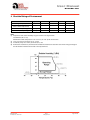
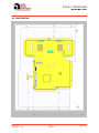
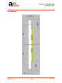
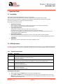
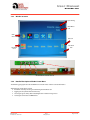
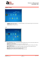
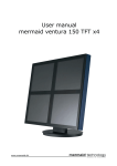
1
USER MANUAL
17” Compact Panel
DI170S01-A01
TFT Display + Backlight inverter + RGB board in one chassis
Orderable P/N: SA-02-015
Rev 1
May 23, 2005
The information given in this document is carefully checked and believed to be reliable. However, Apollo takes no
response for any failure or product damage caused by the application of this information. Please check all
connections carefully with the data sheet. Apollo products are not intended for use in systems in which failures of
product could result in personal injury. All mentioned trademarks are registered trademarks of their owner.
All specifications are subject to change without notification.
flatpanel displays
and solutions
Apollo Display Technologies, LLC
85 Remington Blvd.
Ronkonkoma, NY 11779
USA
Tel.: 631-580-4360
Fax: 631-580-4370
E-Mail: [email protected]
Internet: www.apollodsisplays.com
User Manual
DI170S01-A01
Table of Contents
1 Revision History ............................................................................................................................ 3
2 General Description .................................................................................................................... 3
3 Absolute Maximum Ratings ..................................................................................................... 3
4 Absolute Ratings of Environment .......................................................................................... 4
5 Electrical Specification ............................................................................................................... 5
5.1
Panel Specification............................................................................................................................................................ 5
5.2
Input Signal Characteristics ........................................................................................................................................... 5
5.3
Power Management ......................................................................................................................................................... 5
5.4
5.4.1
5.4.2
5.4.3
Connector Pin Assignment ............................................................................................................................................ 6
CN6: DC Input...................................................................................................................................................................... 6
CN1: Analog RGB Input.................................................................................................................................................... 6
CN2: Key Connector.......................................................................................................................................................... 6
6 Mechanical Specification........................................................................................................... 7
6.1
Front view............................................................................................................................................................................. 7
6.2
Back Side View .................................................................................................................................................................... 8
6.3
Side View 1 ........................................................................................................................................................................... 9
6.4
Side View 2 .........................................................................................................................................................................10
7 Operation Guide.........................................................................................................................11
7.1
Installation..........................................................................................................................................................................11
7.2
7.2.1
7.2.2
7.2.3
7.2.4
OSD Adjustment ..............................................................................................................................................................11
Key Name and Function................................................................................................................................................11
OSD Structure....................................................................................................................................................................12
Window structure ............................................................................................................................................................13
Detailed description of the On-Screen-Menu ......................................................................................................13
8 Appendix.......................................................................................................................................16
8.1
Standard Timing Chart ..................................................................................................................................................16
DI170S01-A01
Product No. : SA-02-015
Rev 1
May 23, 2005
Page 2 of 16
User Manual
DI170S01-A01
1 Revision History
Date
10.02.2005
23.05.2005
Rev.No.
0
1
Description
First release of datasheet
Final release
Page
2 General Description
The DI170S01-A01 from Distec’s CompactPanel Series is an open frame monitor providing an analog RGB interface for
17” SXGA TFT LCD panels with a high quality screen image. This monitor supports from VGA to UXGA resolution at a
maximum of 85Hz refresh rate (refer to point 8.1) with automatic up- and downscaling function to full screen size.
It gives a lot of convenience to the user in installing various applications such as gaming, amusement, industry and so
on and accessing the GUI (Graphic User Interface).
The DI170S01-A01 is a
certified product.
3 Absolute Maximum Ratings
ITEM
Model Name
LCD Module
DESCRIPTION
DI170S01-A01
LTM170EU-L21
Input Signal
Analog RGB
DC 12V/2.6A *
Horizontal: Typ. 64, Max. 82.1 KHz
Vertical: Typ. 60, Max. 77 Hz
Analog RGB : VGA/SVGA/XGA/SXGA/UXGA
DC Jack, KEY Connector, RGB Connector
5 Buttons Controls
gm2121
31W Max *
Resolution
Receptacle
User Controls
Image Scaler
Power Consumption
Dimension
Plug & Play
Power Management
DI170S01-A01
Product No. : SA-02-015
REMARKS
Refer to the clause 5.1 Panel
Specification
* Measured at 23°C ambient temperature
Special timing available
1600x1200 @ 60Hz Max.
Genesis Microchip
* Measured at 23°C ambient temperature
Refer to the clause 6.1
VESA
DDC 2B
Supports VESA DPMS
Rev 1
May 23, 2005
Page 3 of 16
User Manual
DI170S01-A01
4 Absolute Ratings of Environment
Item
Storage temparature
Operating temparature
(Glass surface temperature)
Shock (non-operating)
Vibration (non-operating)
Symbol
TSTG
TOPR
Min.
-25
0
Max.
60
50
Unit
°C
°C
Note
(1)
(1)
Snop
Vnop
-
50
1.5
G
G
(2), (4)
(3), (4)
Note
(1) Temperature and relative humidity range are shown in the figure below.
90 % RH Max. (40 °C ≥ Ta)
Maximum wet-bulb temperature at 39 °C or less. (Ta > 40 °C) No condensation.
(2) 11 ms, sine wave, one time for ±X, ±Y, ±Z axis
(3) 10-300 Hz, Sweep rate 10 min, 30 min for X, Y, Z axis
(4) At vibration and shock test, the fixture which holds the module to be tested has to be hard and rigid enough so
that the module would not be twisted or bent by the fixture.
DI170S01-A01
Product No. : SA-02-015
Rev 1
May 23, 2005
Page 4 of 16
User Manual
DI170S01-A01
5 Electrical Specification
5.1 Panel Specification
Item
Type No.
Size
Active Display Area
Number of Pixels
Pixel Arrangement
Pixel Pitch
Color Depth
Surface Treatments
Viewing Angle
Contrast Ratio
Response Time
(CR≥ 10)
Average Brightness
Frame Rate
Panel Dimension
CCFL
Description
Samsung LTM170EU-L21
17” Diagonal
337.92 x 270.336
1280 (H) x 1024 (V)
RGB Vertical Stripe
0.264 x 0.264
16.2M True Color
Hard Coating (3H), Haze 25%
Horizontal :
ӨL
75
ӨR
75
Vertical :
ΦH
75
ΦL
60
Typ. 700 : 1
Rise time (tr) : 2 ms(Typ.)
Fall time (tf) : 6 ms(Typ.)
Typ. 300 cd/m2
Typ. 60Hz, Max. 77Hz
(WHD) 358.5 x 296.5 x 17.5
4 (2 Dual)
Unit
Inch
mm
mm
degree
mm
5.2 Input Signal Characteristics
Input Signal
DC input
15Pin D-Sub
Description
DC Voltage
Power
Consumption
Video(SOG)
Sync Voltage
Horizontal
Frequency
Vertical
Frequency
Unit
Vdc
Watts
Min
11.4
Typical
12
26
Max
12.6
31
for full Option
1.0
75Ω Terminated
82.082
Depends on Mode
77
Depends on Mode
Vp-p
Vp-p
kHz
56.7
0.7
5.0
64
Hz
55
60
Remarks
5.3 Power Management
VESA DPMS standard is applied for power management control
Mode
HSync.
VSync.
LED (red)
LED (grn)
On
Stand-by
Suspend
Off
Active
Inactive
Active
Inactive
Active
Active
Inactive
Inactive
Off
Blinking
Blinking
Off
On
Off
Off
Off
DI170S01-A01
Product No. : SA-02-015
Rev 1
May 23, 2005
Power Consumption
(nominal)
< 31 W
<3W
Page 5 of 16
User Manual
DI170S01-A01
5.4 Connector Pin Assignment
5.4.1
CN6: DC Input
Part No.
PHR-4
(JST)
5.4.2
Description
GND
Vcc(12V/5A)
Remarks
CN1: Analog RGB Input
Part No.
S13B-PH-SM3-TB
(JST)
5.4.3
Pin No.
1,2
3,4
Pin No.
1
2
3
4
5
6
7
8
9
10
11
12
13
Description
CABLE DETECT
DDC SDA
DDC SCL
RED GND
RED INPUT
GREEN GND
GREEN INPUT
BLUE GND
BLUE INPUT
NC
VERTICAL SYNC
SYNC GND
HORIZONTAL SYNC
Remarks
Description
LED2
LED1
GND
POWER
GND
MENU
RIGHT (Brightness +)
NC
NC
LEFT (Brightness -)
EXIT
AUTO
GND
+3.3V (100mA)
Remarks
CN2: Key Connector
Part No.
53261-1490
(MOLEX)
DI170S01-A01
Product No. : SA-02-015
Pin No.
1
2
3
4
5
6
7
8
9
10
11
12
13
14
Option in 8 keys
Option in 8 keys
Rev 1
May 23, 2005
Page 6 of 16
User Manual
DI170S01-A01
6 Mechanical Specification
6.1 Front view
DI170S01-A01
Product No. : SA-02-015
Rev 1
May 23, 2005
Page 7 of 16
User Manual
DI170S01-A01
6.2 Back Side View
DI170S01-A01
Product No. : SA-02-015
Rev 1
May 23, 2005
Page 8 of 16
User Manual
DI170S01-A01
6.3 Side View 1
DI170S01-A01
Product No. : SA-02-015
Rev 1
May 23, 2005
Page 9 of 16
User Manual
DI170S01-A01
6.4 Side View 2
DI170S01-A01
Product No. : SA-02-015
Rev 1
May 23, 2005
Page 10 of 16
User Manual
DI170S01-A01
7 Operation Guide
7.1 Installation
This monitor is designed for RGB monitor using 17” TFT LCD panel.
This section provides some guidelines for assembly and preparation of a finished display solution.
Before proceeding, it is important to familiarize yourself with the parts making up a system and the various
connectors, mounting holes and general layout of the monitor.
Please follow the below procedure.
1.
2.
3.
4.
Appearance Inspection
Please check the monitor whether it is damaged in appearance or not during transportation.
And assemble this monitor to your system or applications.
Signal Inputs Connection
Analog input is available. Please refer to the clause 5.4 Connector
Pin Assignment and connect the signal what you want to apply to the monitor.
Especially, the Analog RGB cable may affect the visual characteristics and regulatory emission test. So, a
suitably shielded cable should be used.
Power Input Connection
Refer to the 5.4 Connector Pin Assignment and connect the power input cable to the monitor.
Every connection is done but you should consider electrical insulation, grounding, EMI shielding and heat &
ventilation.
Apply Power
Apply power and turn on the monitor and refer to the following clause.
7.2 OSD Adjustment
DI170S01-A01 gives a various and very easy graphics interface to its users. Users have easy access to the functions that
they want to adjust. Be sure that your system’s power and LED are turned on, before the OSD controls are being used.
7.2.1
Key Name and Function
Key name
Power
Menu
Exit
Left
Right
Description
Turns ON/OFF the system
- Opens the main menu
- Confirmation button for selected menu points
- Back to the sub menu
- Goes directly to the exit icon, when the OSD main or sub menu is shown.
The exit icon must still be confirmed via the Menu – button to leave the OSD menu!
- Activates directly the brightness menu
- To decrease setting bars
- Menu icon selection to the left
- Activates directly the contrast menu
- To increase setting bars
- Menu icon selection to the right
Accessing the menu system
1.
2.
With the OSD off, push the Menu button to activate the main OSD menu.
Use the Left and Right buttons to move through the main menu. To select a desired sub menu, press the
Menu button after your selection. The selection tabs are also highlighted and explained via onscreen text in
the upper right of the OSD screen.
DI170S01-A01
Product No. : SA-02-015
Rev 1
May 23, 2005
Page 11 of 16
User Manual
DI170S01-A01
3.
4.
5.
7.2.2
After selecting a sub menu, use the Left or Right buttons to move through the sub menu. To select a setting
icon, press the Menu button after your selection. The selected icons are highlighted and explained via
onscreen text in the lower right of the OSD screen.
There are two types of icons: Some have a single function and must be confirmed with the Menu button, the
other option are setting bars. Once a setting bar appears, it can be increased or decreased via the Left and
Right buttons. The setting bar moves and the numeric value indicator changes to reflect your adjustments.
NOTE: The numeric value indicator is provided as a point of reference only and has nothing to do with a real
measurement.
There are many ways to close the OSD menu:
- Waiting some seconds (timeout). This time can be adjusted as needed in one of the menus.
- In the main and sub menu, press the Exit button. This highlights the “Exit” icon in the menu. Then press the
Menu button to leave the OSD menu.
- After an Autoadjust and confirmation the OSD menu closes automatically.
- After adjusting a setting, press the Menu button to go back to the sub menu, then press the Exit button or
use the Right button to select the “Exit” icon. Confirm via the Menu button and the OSD turns off.
OSD Structure
Main Menu
Brightness
Contrast
Brightness
Contrast
Black Level
Color
Auto Color
sRGB
Color Temperature
User
CMY
4200K
Flesh Tone
5000K
Hue
6500K
Saturation
7500K
9300K
Image
Autoconfiguration
Width
Phase
Horizontal Position
Vertical Position
Tools
OSD
OSD Timeout
Factory Reset
OSD Hor. Position
Sharpness
OSD Ver. Position
OSD Size
Autoconfiguration
Fast
Normal
DI170S01-A01
Product No. : SA-02-015
Rev 1
May 23, 2005
Page 12 of 16
User Manual
DI170S01-A01
7.2.3
Window structure
Input Timing
Main Menu
Info
Main
Menu
Exit Icon
Sub Menu
Info
Sub Menu
Icons
Available OSD controller boards
7.2.4
Detailed description of the On-Screen-Menu
The following paragraphs describe the OSM main and sub-menus and the associated functions.
Adjusted menu items will be saved if:
• the OSM is closed by selecting and confirming the Exit Menu icon
• toggling the sleep mode with the Power Key
• selecting the green smiley after Autoconfiguration in Color or Image menu
• resetting the color value to sRGB default
DI170S01-A01
Product No. : SA-02-015
Rev 1
May 23, 2005
Page 13 of 16
User Manual
DI170S01-A01
Brightness – Contrast
-
Brightness: Adjusts display brightness. If supported, brightness will be regulated using the connected inverter.
Contrast: Adjusts image contrast
Black Level: Adjusts image black level
Color
-
Autoconfiguration: Performs a calibration of the ADC for optimum colors. For best result, black and white level
should be present in the image.
sRGB: Return to default sRGB color values (also activates sRGB color space)
Color Temperature: Allows you to choose different values for the color temperature including a user defined
setting in RGB color space.
CMY: Modify the proportion of cyan, magenta and yellow in the image (also activates CMY color space)
Flesh Tone: Adjusts flesh tone of the image (requires sRGB color space)
Hue: Adjusts hue of the image (requires sRGB color space)
Saturation: Adjusts saturation of the image (requires sRGB color space)
DI170S01-A01
Product No. : SA-02-015
Rev 1
May 23, 2005
Page 14 of 16
User Manual
DI170S01-A01
Image
-
Autoconfiguration: Optimizes the displayed image. Adjusts phase and image position automatically.
Width: Adjusts image width.
Phase: Adjusts image phase.
Horizontal position: Adjusts horizontal image position.
Vertical position: Adjusts vertical image position
Tools & OSD
-
-
OSD
•
•
•
•
OSD Timeout: The OSD vanishes after a certain time of inactivity. Values of 2-16s are possible
OSD Horizontal Position: Adjusts position horizontally
OSD Vertical Position: Adjusts position vertically
OSD Size: Doubles size of OSD (only valid if display resolution is 2 times larger than the OSD size)
Factory reset: Return to factory default values
Sharpness: Modifies the image filtering with shrinking and expansion
Autoconfiguration Type
• Fast: Quick autoadjustment method (coarse adjust for fast resolution switching, like during bootup)
• Normal: Standard autoadjustment method (fine adjustment once the system is displayed properly)
DI170S01-A01
Product No. : SA-02-015
Rev 1
May 23, 2005
Page 15 of 16
User Manual
DI170S01-A01
8 Appendix
8.1 Standard Timing Chart
Mode
Active Resolution
Total
Horizontal
H-
Vertical
V-
Pixel
Failsafe
Pixels
Frequency
Pol.
Freq
Pol.
Clock
Mode
N
31,5
X
(KHz)
VGA
SVGA
(Hz)
640x350 @ 85Hz
832x445
37,861
P
85,08
640x400 @ 85Hz
832x445
37,861
N
85,08
P
31,5
X
720x400 @ 85Hz
936x446
37,927
N
85,039
P
35,5
X
640x480 @ 60Hz
800x525
31,469
N
59,94
N
25,175
640x480 @ 72Hz
832x520
37,861
N
72,809
N
31,5
640x480 @ 75Hz
840x500
37,5
N
75
N
31,5
640x480 @ 85Hz
832x509
43,269
N
85,008
N
36
800x600 @ 56Hz
1024x625
35,156
N/P
56,25
N/P
36
800x600 @ 60Hz
1056x628
37,879
P
60,317
P
40
800x600 @ 72Hz
1040x666
48,077
P
72,188
P
50
800x600 @ 75Hz
1056x625
46,875
P
75
P
49,5
800x600 @ 85Hz
1048x631
53,674
P
85,061
P
56,25
1024x768 @ 60Hz
1344x806
48,363
N
60,004
N
65
1024x768 @ 70Hz
1328x806
56,476
N
70,069
N
75
1024x768 @ 75Hz
1312x800
60,023
P
75,029
P
78,75
1024x768 @ 85Hz
1376x808
68,677
P
84,997
P
94,5
1152x864 @ 75Hz
1600x900
67,5
P
75
P
108
1280x1024 @ 60Hz
1688x1066
63,981
P
60,02
P
108
1280x1024 @ 75Hz
1688x1066
79,976
P
75,025
P
135
EGA
640x350 @ 70Hz
800x449
31,469
P
70,086
N
25,175
CGA
640x400 @ 70Hz
800x449
31,469
N
70,086
P
25,175
DOS
720x350 @ 70Hz
900x449
31,469
P
70,087
N
28,322
DOS
720x400 @ 70Hz
900x449
31,469
N
70,087
P
28,322
XGA
1024x768 @ 72Hz
1304x798
57,515
P
72,1
P
75
XGA
1024x768 @ 87Hz(i)
1264x817
35,522
P
43,479
P
44,9
640x480 @ 67Hz
864x525
35
N
66,667
N
30,24
SVGA
832x624 @ 75Hz
1152x667
49,725
N
74,551
N
57,283
XGA
1024x768 @ 60Hz
1312x813
48,78
N
60,001
N
64
SXGA
1280x1024 @ 60Hz
1708x1056
63,337
N
59,978
N
125
1280x1024 @ 72Hz
1728x1085
78,125
N
72,005
N
135
1280x1024 @ 67Hz
1696x1056
70,755
N
67,003
N
120
XGA
SXGA
SXGA
X
X
X
X
1280x960 @ 60Hz
1800x1000
60
P
60
P
108
1280x1024 @ 85Hz
1728x1072
91,146
P
85,024
P
157,5
X
1280x960 @ 85Hz
1728x1011
85,934
P
85,002
P
148,5
X
P
70
P
VGA
640x400 @ 56Hz
UXGA
1600x1200 @ 60Hz
1152x864 @ 70Hz
1600x900
X
1280x768 @ 60Hz
1280x720 @ 60Hz
DI170S01-A01
Product No. : SA-02-015
Rev 1
May 23, 2005
Page 16 of 16