1
Operator's Manual
Zero Turn Riding Mower
26HP B&S Engine / Side Discharge / 52-inch Wide
Model 127.28875
· Español, p. 37
CAUTION: Before using this product,
read the manual and follow all its Safety
Rules and Operating Instructions
For answers to your questions
about this product call:
1-800-659-5917
Sears Craftsman Help Line
5am - 5pm, Mon - Sat
Sears, Roebuck and Co., Hoffman Estates, IL 60179 U.S.A
Visit the Craftsman website: www.sears.com/craftsman
MAN 4163202 Rev. A 11-2007
PARTS MANUAL 4163201
CALIFORNIA
WARNING
Proposition 65 Warning
Diesel engine exhaust and some
of its constituents are known to the
State of California to cause cancer,
birth defects and other reproductive
harm.
The engine exhaust from this product
contains chemicals known to the State
of California to cause cancer, birth
defects or other reproductive harm.
Californie Proposition 65 Avertissement
Les échappements des moteurs diesel et certains
de leurs composés sont reconnus par l’Etat de
Californie pour être cancérigènes, provoquer
des défauts congénitaux et d’autres dangers en
matière de reproduction.
California Advertencia
Avertissement
L’émission du moteur de ce matériel contient des produits chimiques que l’Etat de
Californie considère être cancérigènes,
provoquer des défauts congénitaux et
d’autres dangers en matière de reproduction.
de la Proposicion 65
El estado de California hace saber que
los gases de escape de los motores diesel
y algunos de sus componentes producen
cáncer, defectos de nacimiento y otros
daños en el proceso de reproducción
humana.
Advertencia
El estado de California hace saber que los
gases de escape de este producto contienen
productos quÍmicos que producen cáncer,
defectos de nacimiento y otros daños en
el proceso de reproducción humana.
CALIFORNIA
Proposition 65 Warning
Battery posts, terminals, wiring
insulation, and related accessories
contain lead and lead compounds,
chemicals known to the State of
California to cause cancer and birth
defects or other reproductive harm.
WASH HANDS AFTER HANDLING.
TABLE OF CONTENTS
PAGE
SAFETY..........................................................................................................................................................2-8
LABELS........................................................................................................................................................9-13
CONTROLS................................................................................................................................................14-17
PRE-OPERATION CHECK LIST..................................................................................................................... 18
OPERATION...............................................................................................................................................19-21
MAINTENANCE CHART................................................................................................................................. 22
MAINTENANCE RECORD . ........................................................................................................................... 23
MAINTENANCE.........................................................................................................................................24-30
ADJUSTMENTS ........................................................................................................................................31-33
BELT REPLACEMENT.................................................................................................................................... 34
SERVICE INFORMATION.............................................................................................................. BACK PAGE
WARRANTY
CRAFTSMAN PROFESSIONAL LIMITED WARRANTY
Two Years on Tractor
When operated and maintained according to all supplied instructions, if this tractor fails due to a defect in
material or workmanship within two years from the date of purchase, call 1-800-4-MY-HOME® to arrange for
free repair.
This warranty applies for only one year from the date of purchase if this tractor is ever used for commercial or
rental purposes.
During the first 30 days of purchase, there will be no charge to service the tractor in your home. For your convenience, in-home warranty service will still be available after the first 30 days of purchase, but a trip charge
will apply. This charge will be waived if you transport the tractor to an authorized Craftsman drop-off location.
For the nearest authorized location, call 1-800-MY-HOME®.
90-Days on Battery
For ninety (90) days from the date of purchase, if the battery included with this tractor is defective in material
or workmanship (our testing proves it will not hold a charge), it will be replaced free of charge.
During the first 30 days of purchase, there will be no charge to replace the defective battery in your home.
For your convenience, in-home warranty service will still be available after the first 30 days of purchase, but a
trip charge will apply. This charge will be waived if you transport the tractor to an authorized Craftsman dropoff location. For the nearest authorized location, call 1-800-MY-HOME®.
This warranty covers ONLY defects in material and workmanship. Sears will NOT pay for:
• Expendable items that become worn during normal use, including but not limited to blades,
spark plugs, air cleaners, belts, and oil filters.
• Standard maintenance servicing, oil changes, or tune-ups.
• Tire replacement or repair caused by punctures from outside objects, such as nails, thorns,
stumps, or glass.
• Tire or wheel replacement or repair resulting from normal wear, accident, or improper operation
or maintenance.
• Repairs necessary because of operator abuse, including but not limited to damage caused by
towing objects beyond the capability of the tractor, impacting objects that bend the frame or
crankshaft, or over-speeding the engine.
• Repairs necessary because of operator negligence, including but not limited to, electrical and
mechanical damage caused by improper storage, failure to use the proper grade and amount
of engine oil, failure to keep the deck clear of flammable debris, or failure to maintain the
equipment according to the instructions contained in the operator's manual.
• Engine (fuel system) cleaning or repairs caused by fuel determined to be contaminated or
oxidized (stale). In general, fuel should be used within 30 days of its purchase date.
• Normal deterioration and wear of the exterior finishes, or product label replacement.
This warranty applies only while this product is within the United States.
This warranty gives you specific legal rights, and you may also have other rights, which vary, from state to
state.
Sears, Roebuck and Co., Hoffman Estates, IL 60179
11-2007
1
SAFETY
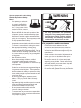
NOTICE !!!
This symbol means:
Unauthorized modifications may present extreme
safety hazards to operators and bystanders and
could also result in product damage.
ATTENTION!
BECOME ALERT!
Your safety and the safety of others is involved.
Craftsman Professionalstrongly warns against,
rejects and disclaims any modifications, add-on
accessories or product alterations that are not
designed, developed, tested and approved by
Craftsman Professional Engineering Department.
Any Craftsman Professional product that is altered,
modified or changed in any manner not specifically
authorized after original manufacture–including the
addition of “aftermarket” accessories or component
parts not specifically approved by Craftsman
Profesional–will result in the Craftsman Professional
Warranty being voided.
Any and all liability for personal injury and/or property
damage caused by any unauthorized modifications,
add-on accessories or products not approved
by Craftsman Professional will be considered
the responsibility of the individual(s) or company
designing and/or making such changes. Craftsman
Professional will vigorously pursue full indemnification
and costs from any party responsible for such
unauthorized post-manufacture modifications and/or
accessories should personal injury and/or property
damage result.
Signal word definitions:
The signal words below are used to identify levels
of hazard seriousness. These words appear in
this manual and on the safety labels attached
to Craftsman Professional machines. For your
safety and the safety of others, read and follow the
information given with these signal words and/or
the symbol shown above.
DANGER indicates an imminently hazardous
situation which, if not avoided, will result in death
or serious injury.
WARNING indicates a potentially hazardous
situation which, if not avoided, could result in
death or serious injury.
CAUTION indicates a potentially hazardous situation
which, if not avoided, may result in minor or moderate
injury. It may also be used to alert against unsafe
practices or property damage.
CAUTION used without the safety alert symbol
indicates a potentially hazardous situation which, if
not avoided, may result in property damage
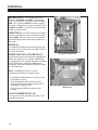
MODEL NUMBER: This number appears on sales literature, technical manuals and
price lists.
SERIAL NUMBER: This number appears only on your mower. It contains the model
number followed consecutively by the serial number. Use this number when ordering
parts or seeking warranty information.
Serial Number Tag is located under seat; on the far back wall of the frame; left of battery
from operators point of view.
2
SAFETY
PREPARING FOR SAFE OPERATION
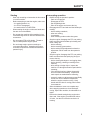
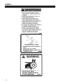
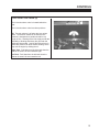
WARNING
Operator preparation and training
Read the Operation & Safety
Manual
- If an operator or mechanic
cannot read English, it is
the owner's responsibility
to explain this material to
them. If any portion of this
material is unclear, contact
your factory representative for clarification.
All rotary lawnmowers are potentially
dangerous. They can amputate hands and
feet and throw objects. Failure to follow
these safety and operating instructions
could result in serious injury or death.
- Become familiar with the safe operation of the
equipment, operator controls and safety signs.
Know how to stop the engine and attachments
quickly in an emergency. Do not operate or allow
another person to operate this machine if there
are any questions about safety.
-
All operators and mechanics should be trained.
The owner is responsible for training the users.
-
Wear appropriate clothing, including long
trousers and safety goggles or safety glasses
with side shields when operating mower. Do not
operate barefoot or wearing open sandals. Long
hair, loose clothing or jewelry may get tangled in
moving parts.
Site preparation and circumstances
-
Evaluate the terrain to determine what
accessories and attachments are needed to
properly and safely perform the job. Only use
accessories and attachments approved by the
manufacturer.
-
Clear the area to be mowed of objects such as
rocks, toys, wire or other debris that may be
picked up or thrown by the mower.
-
Wear hearing protection.
-
Never allow underage children, unskilled
or improperly trained people operate this
equipment. Local regulations can restrict the age
of the operator.
-
Be sure the area is clear of pets and people,
especially young children. Never assume they
will remain where you last saw them. Stop the
machine if any enter the area.
-
Data indicates that those operators age 60 years
and above are involved in a large percentage of
riding mower-related injuries. Those operators
should evaluate their ability to operate the riding
mower safely enough to protect themselves and
others from injury.
-
Mow only in daylight or in good artificial light.
-
Do not mow wet grass as tires may lose traction.
-
Do not carry passengers, especially small
children. They may fall off and be seriously
injured.
- Keep warning labels and this operator's manual
legible and intact. Replacement labels and
manuals are available from the factory.
- Do not operate machine while under the
influence of drugs or alcohol.
-
The owner/user can prevent and is responsible
for accidents or injuries occurring to themselves,
other people or property.
3
SAFETY
Machine preparation
OPERATING SAFELY
-
Check operator presence interlock system and
brake operation. Adjust or repair any problems
before using.
In general
-
Use extra care when loading or unloading the
machine into a trailer or truck.
-
Do not tamper with or defeat safety devices.
Keep guards, shields and interlock safety devices
in place and in proper working condition. They
are for your protection.
-
Slow down and use caution when making turns
and crossing roads and sidewalks. Stop blades if
not mowing.
-
-
Keep all fasteners such as nuts, bolts and pins
well secured.
Do not run the engine in an enclosed area where
dangerous carbon monoxide fumes can collect.
-
-
Visually inspect blades, blade bolts and the cutter
assembly for wear or damage. Replace worn or
damaged blades and bolts to preserve balance.
Do not place your foot on the ground while
operating the machine.
-
Before operating, lower the discharge chute,
install the mulcher or put the entire grass catcher
in place.
-
Keep clear of the discharge opening at all times.
Never direct the discharge toward a bystander.
Stop operation if someone approaches.
-
Keep washout ports and other mower housing
service openings closed when mowing.
-
Use care when pulling loads or using heavy
equipment.
- Use only approved draw bar hitch points.
- Limit loads to those you can safely control.
- Do not turn sharply. Use care when reversing.
- Use counter-weight(s) or wheel weights when
suggested in the operator's manual.
-
Verify that machine and attachments, if any, are
in good operating condition.
-
Do not engage blades until ready to mow.
-
4
Never leave a machine unattended. Always turn
off blades, set parking brake, stop engine and
remove key before dismounting.
SAFETY
Starting
Interrupting operation
-
Start only according to instructions in this manual
or on the machine.
-
Before attempting to start the engine, make sure:
- the parking brake is on;
- the PTO is disengaged;
- the traction drive is in NEUTRAL.
-
Before leaving the operator's position:
- Park on level ground.
- Disengage the PTO.
- Set the parking brake.
- Shut off the engine and remove the key.
-
-
When starting the engine, make sure hands and
feet are clear of the blades.
Disengage the PTO and wait until the blades quit
rotating:
- before raising cutterdeck;
- when not mowing;
- for transport;
- when crossing surfaces other than grass.
-
Do not start the machine while standing in front
of the discharge chute or with the chute directed
at someone.
-
Do not engage PTO at full throttle. Throttle to
idle or lowest possible engine speed.
-
Do not change engine governor settings or
over-speed the engine. Operating the engine
at excessive speed can increase the hazard of
personal injury.
-
-
Stop the engine, disengage the PTO, set parking
brake and wait until the blades quit rotating and
lower cutting unit:
- before refueling;
- before removing grass catcher;
- before making height adjustment unless the
adjustment can be made from the operator's
position.
Stop the engine, disengage the PTO, set parking
brake and disconnect the spark plug wire(s) or
remove the key:
- before clearing blockages or unclogging chute;
- before checking, cleaning or working on the
machine;
- after striking a foreign object. Inspect the
machine for damage and make repairs before
restarting;
- if the machine begins to vibrate abnormally:
shut off machine immediately. Inspect and
make repairs as needed before restarting;
- except for repairs or adjustments as specifically
noted, such as for carburetor adjustment,
where the engine must be running. Keep
hands and feet clear of moving parts in these
circumstances.
-
Allow the blades to come to a complete stop
when stopping operation to clear blockages,
unclog, inspect the machine, do maintenance or
repair.
-
Reduce the throttle setting during engine shutdown and, if the engine is provided with a shutoff valve, turn the fuel off at the conclusion of
mowing.
5
SAFETY
MANEUVERING SAFELY
In general
gradual. Do not make sudden changes in speed
or direction.
-
Slow down before turning.
-
Do not mow in reverse unless absolutely
necessary. Always look behind and down
for small children and pets before and during
backing.
-
Do not turn on slopes unless necessary, and then
turn slowly and downhill when possible.
-
Stay away from slopes if the ground is loose or if
caught in the rain during mowing.
-
Be aware when approaching blind corners,
shrubs, trees, tall grass or other objects that may
obscure vision.
-
Use lower speeds on a slope to avoid stopping or
shifting.
-
If tires lose traction, disengage the blades. If on
a slope, head downhill.
-
Use extra care with grass catchers or other
attachments. These can change the stability of
the machine.
-
Remove obstacles such as rocks, tree limbs etc.
-
Avoid driving over obstacles such as ruts, holes,
rocks and roots whenever possible. Be alert to
dips and rises. Uneven terrain can overturn a
mower or cause it to slide. Tall grasses can hide
obstacles.
-
Do not mow drop-offs, ditches or embankments.
The machine could suddenly turn over if a wheel
runs over the edge or an edge caves in.
-
Follow the manufacturer's recommendations
for wheel weights or counterweights to improve
stability.
-
Do not mow slopes when grass is wet. Reduced
traction could cause sliding.
Mowing slopes
WARNING
Slopes are a major factor in
loss-of-control and tip over
accidents that sometimes lead
to severe injury or death. All
slopes require extra caution.
-
Do not mow on slopes if uneasy or uncertain.
Ultimate responsibility for safe operation on
slopes rests with the operator.
-
Do not mow excessively steep slopes.
A slope is too steep if:
· The machine will not back up the slope.
· The machine must be crabbed (turned
partially sideways uphill) to drive across
the slope.
· The machine turns downhill going across slope.
· You are uneasy about being on the slope.
-
On zero turn machines, mow across slopes, not
up and down.
-
Avoid starting or stopping on a slope. If tires
lose traction, disengage the blades and proceed
slowly straight down the slope.
-
With a zero turn machine, if tires lose traction
going down a slope, steering control may be
regained by speeding up.
-
Mid-mount zero turns (belly mounted deck) have
much greater traction pointed up slope than
down slope. Be aware that traction may be lost
going down a slope. Do not operate a mid-mount
zero turn on slopes it cannot back up.
-
Keep all movement on the slopes slow and
6
SAFETY
MAINTENANCE SAFETY
In general
-
Maintain machine according to manufacturer's
schedule and instructions for maximum safety
and best mowing results.
-
Park machine on level ground.
-
Never allow untrained personnel to service machine.
-
Adjust or repair only after the engine has been
stopped and the blades have quit rotating.
-
Inspect grass catcher components regularly. If
worn, damaged or deteriorated, they may expose
moving parts or allow objects to be thrown.
-
Replace parts if worn, damaged or faulty.
For best results, always replace with parts
recommended by the manufacturer.
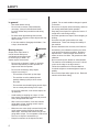
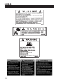
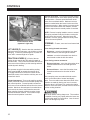
Blades
WARNING
-
Mower blades are sharp and
can cut. Use extra caution
when handling. Remove obstructions with care. Wrap the
blade(s) or wear gloves.
-
Be aware that rotating one
blade on multi-blade mowers can cause other
blades to rotate.
-
Only replace blades. Never straighten or weld
them.
-
Keep other persons away from blades.
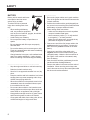
WARNING
Fuel
-
Disconnect battery or remove spark plug wire(s)
before making any repairs. Disconnect the
negative terminal first and the positive last. Reconnect positive first and negative last.
-
Gasoline and diesel fuels are
flammable; gasoline vapors
are explosive. Use extra care
when handling.
-
Do not dismantle the machine without releasing
or restraining forces which may cause parts to
move suddenly.
-
Store only in containers specifically designed for fuel.
-
When refueling or checking fuel level:
- Stop the engine and allow to cool;
- Do not smoke;
- Refuel outdoors only;
- Use a funnel;
- Do not overfill;
- If fuel is spilled, do not attempt to start the
engine until the spill is cleaned up and vapors
have cleared.
-
Do not fill containers in a vehicle or on a truck or
trailer bed with a plastic liner. Fill containers on
the ground away from the vehicle.
-
When practical, remove gas powered equipment from the truck or trailer and refuel it on the
ground. If equipment must be refueled on the
truck or trailer, refuel from a portable container
rather than a dispenser nozzle.
Keep the dispenser nozzle in contact with the rim
of the fuel tank or container opening until fueling
is complete. Do not use a nozzle lock-open
device.
-
Replace caps on fuel cans and tanks securely.
-
Provide adequate support, e.g. jackstands for
lifted machine or parts if working beneath.
-
Do not put hands or feet near or under rotating
parts.
-
Clean up spilled oil or fuel thoroughly.
-
Replace faulty mufflers.
- To reduce fire hazards, keep the engine, muffler,
battery compartment and fuel storage area free
of grass, leaves, debris buildup or grease.
- Hydraulic fluid can penetrate skin, use paper
to check for leaks. Relieve hydraulic pressure
before disconnecting hoses. Make sure
connections are tight and hoses are in good
condition.
7
SAFETY
BATTERY
WARNING
Jump starting
Battery acid is caustic and fumes
are explosive and can cause
serious injury or death.
1. Be sure the jumper cables are in good condition.
Turn off the ignition and all electrical accessories
on both machines.
To reduce the risk of personal
injury when working near a battery:
2. Position the machine with a good (charged) battery next to but not touching the machine with the
dead battery so jumper cables will reach.
- When working with battery
acid, use protective equipment
such as, but not limited to, goggles, face shield,
rubber gloves and apron.
3. When making cable connections:
-
Avoid leaning over a battery.
-
Do not expose a battery to open flames or
sparks.
-
Be sure batteries with filler caps are properly
filled with fluid.
-
Do not allow battery acid to contact eyes or skin.
Flush any contacted area with water immediately
and get medical help.
-
Charge batteries in an open, well ventilated area,
away from sparks and flames. Unplug charger
before connecting or disconnecting from battery. - make sure the clamps do not touch anywhere
except to intended metal parts,
- Never connect a positive ("+" or red) terminal
to a negative ("–" or black) terminal.
- Make sure the cables won't get caught in any
parts after the engines are started.
4. Connect one end of the first jumper cable to the
positive terminal on one battery. Connect the
other end to the positive terminal on the other
battery.
5. Connect one end of the other cable to the
negative terminal of the machine with a good
(charged) battery. Make the final connection on
the engine of the machine to be started, away
from the battery.
6. Start the vehicle with the good battery, then the
machine with the discharged battery.
TRANSPORTATION AND STORAGE SAFETY
-
Stop the engine and allow to cool before storing.
-
Drain the fuel tank outdoors only.
- Store fuel in an approved container in a cool, dry
place.
-
Keep the machine and fuel containers in a locked
storage place to prevent tampering and to keep
children from playing with them.
-
When the machine is to be parked, stored or left
unattended, lower the cutterdeck unless a positive mechanical lock is used.
-
Do not store the machine or fuel container near
heating appliances with an open flame such as a
water heater or an appliance with a pilot light.
-
Keep gasoline storage area free of grass, leaves
and excessive grease to reduce fire hazard.
-
Clean grass and debris from cutting units, drives,
mufflers and engine to help prevent fires.
8
7. Remove the cables in the exact reverse order of
installation. When removing each clamp, take
care it does not touch any other metal parts while
the other end remains attached.
LABELS
9
LABELS
10
LABELS
11
LABELS
12
LABELS
13
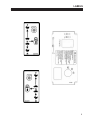
CONTROLS
Keyswitch (K) - The keyswitch has three
positions: OFF, RUN, and START. Insert the key
and turn it clockwise to move the switch from OFF to
RUN. Turn it further to START and hold to engage
the starter. Release the key and the switch will return
to RUN from START. Turn the key counterclockwise
to OFF to stop the engine.
Throttle (T) - Move the throttle lever forward to
increase engine speed until the maximum governed
engine RPM is reached. Move the lever rearward to
decrease engine speed until the engine reaches its
idle speed.
Choke (C)
For Kawasaki and Briggs and Stratton Engines, pull
the choke control out to set the choke ON. Push it in
to set the choke OFF.
Power Take Off (PTO) Switch (P) -
At operator's right side
The operator must be in the seat when engaging the
PTO or the engine will kill. Pulling the PTO switch
out engages (turns on) the PTO and starts the blades
or other attachment. Pushing the PTO switch in
disengages (turns off) the PTO and stops the blades
or other attachment.
NOTE: The PTO switch does not control
attachments powered by a separate engine.
- Disengage the PTO whenever you stop or leave
the operator’s position
- Shut off engine with the key and remove the
spark plug wires before making adjustments or
unplugging a clogged mower.
- Do not engage the PTO until ready to start
mowing.
12 VOLT POWER OUTLET (X)
A 12 volt power outlet is provided to operate 12 volt
personal accessories.
14
Below seat
CONTROLS
FUEL SELECTOR VALVE (U)
The fuel tank selector valve is located behind the
seat.
The fuel tank selector valve has three positions:
Off: The tank selector is off when the lever points
down. The selector should be off whenever the
machine is transported or stands unused for any
length of time. Shutting off the fuel supply avoids the
possibility of flooding should any dirt get under the
carburetor float needle. Leaving the tank selector in
either tank position can allow severe flooding, which
may ruin the engine by diluting the oil.
Right Tank: Fuel flows from the right tank when the
selector is turned 1/4 turn toward the right.
Left Tank: Fuel flows from the left tank when the
selector is turned 1/4 turn toward the left.
15
CONTROLS
Reverse movement - To move the machine straight
back, pull both traction levers back equally from their
neutral position. Reverse speed increases as the
levers are moved back farther. Maximum reverse
speed is reached when the levers hit the rear of the
forward-reverse slot. When moving in reverse, pushing the levers forward slows the machine, and the
machine stops when the neutral position is reached.
NOTE: Reverse is spring loaded to return to neutral.
This spring resistance may be felt when moving the
traction levers into reverse. When the levers are
released in reverse, spring tension will slowly return
them to the neutral position.
Lift and traction levers
(operator's right side)
Steering - To steer, move one lever forward and
one back.
Lift lever (F) - Used to raise the cutterdeck to
Turns during forward movement:
maximum height for transport, curb climbing or blade
changing. To return to preset height of cut, lower lift
lever until it contacts height of cut pin A.
-
Right turn - move the right traction lever back
toward neutral to slow the right drive wheel.
-
Left turn - move the left traction lever back toward neutral to slow the left drive wheel.
Traction Levers (L) - Each of the two
traction levers controls the drive wheel located on
the same side. They control the forward and reverse
movement of the machine, provide steering and also
provide dynamic braking.
Turns during reverse movement:
-
Reverse right turn - move the right traction lever
forward toward neutral to slow the right drive
wheel.
The operator must be in the seat and the parking
brake must be OFF to engage the traction drive.
To engage traction drive, move the traction levers
toward the center of the machine until they are out of
neutral lock slot S.
-
Reverse left turn - move the left traction lever
forward toward neutral to slow the left drive
wheel.
Forward movement - To move the machine straight
ahead, push both traction levers forward equally from
their neutral position. Forward speed increases as
the levers are moved farther forward from the neutral
position. Maximum forward speed is reached when
the levers hit the front of the forward-reverse slot.
When traveling forward, pulling the traction levers
rearward slows the machine. The machine stops
when the neutral position is reached.
16
Slow, sweeping turns are made with both traction
levers on the same side of neutral and slightly
apart. True zero radius turns about the center of the
machine are made by having one lever in reverse
while the other is in forward. By varying the relative
positions of the two levers, the rate of turn is varied to
suit the mowing situation.
Slow down before making sharp turns. The machine
is capable of turning very rapidly when the levers are
moved further apart from each other. Loss of control
and/or turf damage may result.
CONTROLS
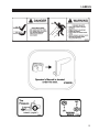
Parking brake (R) - Pull the parking brake
lever up and back to put the parking brake ON. Push
it forward and down to put the parking brake OFF.
The parking brake must be ON to start the engine.
It must also be ON to keep the engine running if the
operator leaves the seat. The parking brake must be
OFF to keep the engine running when a traction lever
is moved out of neutral lock.
Parking brake in ON position
(operator's left side)
Pushing the machine
The machine may be pushed with the engine off, the
parking brake off, and the bypass valves open.
To open the bypass valves, move the parking brake
to the OFF position, then lift and pull bypass control
rod C through the large opening D, until the control
rod stop is past the opening. Drop rod C into the
small opening to lock in place. Repeat for the other
bypass control rod.
To close the bypass valves, lift bypass control rod C
allowing the control rod stop to retract through the
large opening D.
17
PRE-OPERATION CHECK LIST
PRE-OPERATION CHECK LIST
(OPERATOR’S RESPONSIBILITY)
___ Review and follow all safety rules and safety
decal instructions.
___ Check that all safety decals are installed and in
good condition. Replace if damaged.
___ Check to make sure all shields and guards
are properly installed and in good condition.
Be sure that either the discharge shield or
complete vacuum attachment is installed.
___ Check that all hardware is properly installed.
and secured.
___ Check that equipment is properly and securely
attached to power unit.
___ Check to be sure engine is free of dirt and
debris. Pay particular attention to the cooling
fins, governor parts and muffler. Clean air
intake screen. Check air cleaner; service if
necessary.
18
___ Never allow riders.
___ Inspect area and remove stones, branches or
other hard objects that might be thrown,
causing injury or damage.
___ Clean area around oil fill dipstick. Remove
dipstick and check to be sure oil is in operating
range (between marks on dipstick). Add oil if
necessary but Do Not Overfill. Install dipstick
assembly firmly until cap bottoms out on tube.
Dipstick assembly must always be secured into
fill tube when engine is running.
___ Check all lubrication points and grease as
instructed in manual.
___ Check hydrostatic fluid level. Check to be sure
cooling fins on hydrostat are clean.
___ Perform a functional check of the safety
interlock system each time you operate the
unit.
OPERATION
FUELING
- Fill fuel tank with good quality, clean, unleaded
regular gasoline. Do not use hi-test fuel.
- Use a funnel to avoid spilling.
OPERATOR PRESENCE
Interlock System
To start the engine:
- The PTO switch must be OFF.
- Both traction levers must be in the neutral lock
position.
WARNING
- The parking brake must be ON.
To operate the machine:
1. The operator must be in the seat or engaging the
PTO will kill the engine.
TO CHECK OR ADD FUEL:
– Do it outdoors
2. The parking brake must be OFF and the operator must be in the seat, or moving a traction lever
from the neutral lock position will kill the engine.
– Do not smoke
– Stop engine; allow to cool
– Fill to one inch below bottom
of filler neck
STARTING THE ENGINE
– Do not overfill
– Clean up spilled fuel
Before starting the engine
- Be familiar with all controls, how each functions
and what each operates.
- Check the engine oil level and add if necessary.
Using the fuel selector valve, select which tank
will supply fuel
1. Turn the key to operate the electric starter to start
the engine. Release the key when the engine
starts.
2. If the engine does not start immediately, do not
crank for more than 10 seconds at a time. Allow
60 seconds for the starter motor to cool down
between starting attempts to prevent the starter
motor from burning out.
3. If the choke is ON when the engine starts,
gradually back it off until the engine runs with no
choke at all.
- Choke: For cold starts, set the throttle lever to the
half-open position and pull the choke out to the
ON position. For warm starts set the throttle to
the half-open position and the choke to the OFF
position.
19
OPERATION
OPERATING NOTES
Driving
- Practice at slow engine and travel speeds with the
PTO off until fully familiar with the controls.
1. With the PTO disengaged, move the parking
brake to OFF.
- For normal cutting the throttle should be set at the
full open position. By using the traction levers to
speed up or slow down the machine during use,
maximum control and cutting efficiency can be
maintained.
2. - Using the machine at less than full throttle in
heavy conditions will cause the engine to labor
and result in excessive wear.
4. Steering - Move one lever forward and one back.
Move both traction levers out of neutral lock.
3. Push both traction levers forward evenly to
drive forward in a straight line. Pull both traction
levers back evenly to drive backward in a straight
line.
Turns during forward movement:
-
Right turn - move the right traction lever back
toward neutral to slow the right drive wheel.
-
Left turn - move the left traction lever back toward neutral to slow the left drive wheel.
Turns during reverse movement:
-
Reverse right turn - move the right traction lever
forward toward neutral to slow the right drive
wheel.
-
Reverse left turn - move the left traction lever
forward toward neutral to slow the left drive
wheel.
use caution when making turns. Slow down before
making sharp turns to help maintain control and to
prevent torn turf from skidding or spinning tires. To
help prevent turf damage, keep both drive tires moving whenever a turn is made.
TIP: The best way to make a sharp "zero" turn is to
come to a stop, get the machine moving in reverse
with both drive wheels and then power the machine
around with the outside wheel. This technique keeps
the drive tires turning and results in less turf damage.
20
OPERATION
Cutting
1. Place the discharge chute in the down position or
correctly fit a grass collector or mulcher plate.
2. Sit in the seat.
3. Start the engine.
4. Turn the blades on by pulling up on the PTO
switch. Do not start the blades at full throttle.
Instead, use the slowest throttle setting that will allow the engine to pick up the blade load to reduce
the wear on the belts and electric clutch.
5. After the blades are rotating, set the throttle to
maximum. Use the traction levers to obtain the
required cutting speed, to steer around obstacles
and to turn at the end of a cut.
DANGER
ROTATING BLADES
– KEEP HANDS AND FEET AWAY.
– STOP ENGINE AND LET BLADES STOP
BEFORE REMOVING GRASS COLLECTOR OR UNCLOGGING.
WARNING
THROWN OBJECTS
CUTTING TIPS
- When mowing large areas, start by turning to the
right so that clippings will be discharged away
from shrubs, fences, driveways, etc. After two or
three rounds, mow in the opposite direction, left
hand turns, until finished.
– Keep area clear of people
and pets.
– Remove objects blade may
strike and throw.
– Stop blades to cross gravel
areas
– Do not operate without chute,
mulcher or entire grass
CATCHER IN PLACE.
- If grass is extremely tall, it should be mowed
twice, the first cut relatively high, the second cut to
the desired height.
- Use the left side of the mower for trimming.
- Choose cutting directions so that clippings are
thrown onto areas that already have been cut.
This method results in the most even distribution
of clippings and more uniform, better appearing
cuts.
- Use a different mowing pattern each time where
possible. This helps prevent rutting and leads
to a more uniform cut by keeping the grass from
always laying the same way.
21
MAINTENANCE CHART
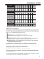
MAINTENANCE
OPERATION
Maintenance is an ongoing job. These intervals are maximum times between
maintenance operations. Perform more often under severe conditions.
FIRST 5
HOURS
BEFORE
EACH
USE
EVERY
25
HOURS
EVERY
50
HOURS
EVERY
100
HOURS
EVERY
200
HOURS
YEARLY
ENGINE
Consult the engine manual for additional information and instructions
Check/Top Up
Oil Level
X
Check For Leaks
X
Clean Air Intake
Screen
X
Clean Air Cleaner
Precleaner
X
Clean Air Cleaner
Element
X
Clean Cooling Fins
Change Oil
Change Oil Filter
X
X
*X
X
X
X
Check/Replace
Spark Plugs
X
X
TRANSAXLE
Check Oil Level
X
Check For Leaks
X
Change Oil And
Filter
X
MACHINE
Check Interlock
Operation
X
Check Tire
Pressures
X
Check Battery
X
Lubricate All Points
*see page 25
Check Hardware
X
X
X
*Change oil after first 5 to 8 hours of use, then every 50 hours. Change oil every 25 hours when
operating the engine under heavy load or in high temperatures.
22
MAINTENANCE RECORD
GENERAL
DATE
HRS
DATE
HRS
DATE
HRS
DATE
HRS
D ATE
HRS
DATE
HRS
C h ec k T i r e P r es s u r es
L u b r i c at e A l l P o i n t s
C h ec k N u t s & B o l t s
ENGINE
Ch ec k Oil L ev el
Ch an g e Oil
C l ean
A i r C l ean er E l em en t
C l ean C o o l i n g F i n s
R ep l ac e
A i r C l ean er E l em en t
Clean & Gap
S p ar k P l u g s
TR A N S A X L E
Ch an g e Oil An d Filt er
NOTE: Af t er f ir s t 5 h o u r s o f o p er at io n c h an g e en g in e o il an d f ilt er.
Repair Protection Agreements
Congratulations on making a smart purchase. Your new Craftsman® Professional product is designed
and manufactured for years of dependable operation. But like all products, it may require repair from
time to time. That's when having a Repair Protection Agreement can save you money and aggravation.
Here's what the Repair Protection Agreement* includes:
Expert Service by our 10,000 professional repair specialists
Unlimited service and no charge for parts and labor on all covered repairs
Product replacement up to $1500 if your covered product can't be fixed
Discount of 10% from regular price of service and related installed parts not covered by the
agreement; also, 10% off regular price of preventative maintenance check
Fast help by phone - we call it Rapid Resolution - phone support from a Sears representative.
Think of us as a "talking owner's manual."
Once you purchase the Repair Protection Agreement, a simple phone call is all that it takes for you to
schedule service. You can call anytime day or night, or schedule a service appointment online.
The Repair Protection Agreement is a risk-free purchase. If you cancel for any reason during the product
warranty period, we will provide a full refund. Or, a prorated refund anytime after the product warranty
period expires. Purchase your Repair Protection Agreement today!
Some limitations and exclusions apply.
For prices and additional information in the U.S.A. call 1-800-827-6655
*Coverage in Canada varies on some items. Full full details call Sears Canada 1-800-361-6665
Sears Installation Service
For Sears professional installation of home appliances, garage door openers, water heaters, and other
major home items, in the U.S.A. or Canada call 1-800-4-MY-HOME®.
23
MAINTENANCE
CHECK DAILY
Operator Presence Interlock System - Start Operation
For the engine to crank, the parking brake must be on, the PTO (blades) off and traction levers in the neutral
lock position. Sit in the seat and check, one by one, if the engine will crank with the parking brake off, the
blades on, and either traction lever out of neutral lock.
Operator Presence Interlock System - Run Operation
The operator must be in the seat for the engine to run with the parking brake off, the traction levers moved out
of the neutral lock position, or the blades on. To check:
1. Start the engine and run at 1/2 throttle with the operator on the machine but raised off the seat.
2. One by one: move the parking brake to the OFF position, traction levers out of the neutral lock position
(check each independently), and turn the blades on. Each check should kill the engine after 1/2 second.
(A 1/2 second delay is built into the system to prevent engine cutout when traversing rough terrain.)
Repair machine before using if the Operator Presence Interlock System does not operate correctly in start or
run.
Hardware
Tighten any nuts and bolts found loose. Replace any broken or missing cotter pins. Repair any other problems before operating.
Tire pressure
Tires should be kept inflated to 14 lbs/in2 (1.0 kg/cm2). Improper tire inflation can cause rapid tire wear and
poor traction. Uneven inflation can cause uneven cutting. Overinflation of caster tires can cause casters to
"wobble" on hard surfaces.
BATTERY
Battery acid is caustic and fumes
are explosive and can cause serious injury or death.
4. Check the electrolyte level every 100 hours of
operation or yearly, whichever comes first. Top
off with distilled water if necessary.
Use insulated tools, wear protective glasses or
goggles and protective clothing when working with
batteries. Read and obey the battery manufacturer’s
instructions.
NOTE: Sealed batteries cannot be checked or
topped off.
Be certain the ignition switch is OFF and the key has
been removed before servicing the battery.
1. Verify battery polarity before connecting or disconnecting the battery cables.
2. When installing the battery, always assemble
the RED, positive ( + ) battery cable first and the
BLACK ground, negative ( - ) cable last.
3. When removing the battery, always remove the
BLACK ground, negative ( - ) cable first and the
red, positive ( + ) cable last.
24
5. Clean the cable ends and battery posts with steel
wool. Use a solution of baking soda and water
to clean the battery. Do not allow the solution to
enter into the battery cells.
6. Tighten cables securely to battery terminals and
apply a light coat of silicone dielectric grease to
terminals and cable ends to prevent corrosion.
Keep terminal covers in place.
MAINTENANCE
LUBRICATION
Every 50 hours of operation, lubricate the following points (1-3) with grease:
1. Deck lift lever (1 point)
2. Deck lift pivots (4 points)
3. Pull arms (2 points located at the front of the cutterdeck)
4. Caster wheel pivots (2 points)
(Lubricate every 500 hours or once a year)
NOTE ON BLADE SPINDLES - The blade spindles on these machines use a
superior sealed bearing that does not require relubrication.
25
MAINTENANCE
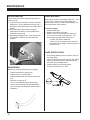
ENGINE OIL
Perform engine maintenance with the engine off,
spark plug wires disconnected and PTO disengaged.
AFTER FIRST FIVE (5) HOURS
While the engine is warm:
1. Remove drain cap at location D and drain the
crankcase. Dispose of used oil in accordance
with local requirements.
2. Clean and replace the cap.
3. Change oil filter.
4. Fill the crankcase with fresh oil to the full mark.
Do not overfill. See engine manual for oil
specifications.
OIL CAPACITY
DAILY
1. Check oil level with the dipstick.
2. If oil is needed, add fresh oil of proper
viscosity and grade. See engine manual for oil
specifications. Do not overfill.
3. Replace dipstick before starting engine.
PERIODIC OIL CHANGES
1. See Page 22 maintenance chart for oil and filter
change intervals after the break-in period.
2. Follow instructions for first oil change, above.
Engine without oil filter holds approximately 1-7/8
quarts (60 ounces; 1.8 liters).
Engine equipped with oil filter holds approximately 2
quarts (64 ounces; 1.9 liters).
Use a high quality detergent oil classifed "For Service
SF, SG, SH, SJ" or higher.
Use recommended SAE viscosity grade oil per starting temperature according to Figure 1.
Figure 1
Synthetic SW-30, 10W-30
Spark Plugs
Remove each plug and check condition.
-
Good operating conditions are indicated if the plug has a light coating of grey or tan deposit.
-
A white blistered coating indicates overheating. A black coating indicates an “over rich” fuel mixture.
Both may be caused by a clogged air cleaner or improper carburetor adjustment.
-
Do not sandblast, wire brush or otherwise attempt to repair a plug in poor condition. Best results are
obtained with a new plug.
-
Set plug gap as specified in engine manual..
26
MAINTENANCE
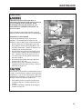
FUEL FILTER
An in-line fuel filter is located in the fuel supply line.
Inspect at every oil change to make sure it is clean
and unobstructed. Replace if dirty.
DUAL ELEMENT AIR CLEANER
Engines equipped with dual element air cleaners
have a paper air cleaner element with an oiled, foam
precleaner element on the dirty side of the paper
element. Both should be inspected regularly and
maintained.
Clean and re-oil precleaner element every 25 hours
(more often under dusty conditions).
1. Disassemble air cleaner cover.
2. Remove precleaner.
3. Wash precleaner in kerosene or liquid detergent
and water.
4. Wrap precleaner in cloth and squeeze to remove
cleaner.
5. Saturate precleaner in engine oil. Squeeze to
remove excess oil.
6. Re-install precleaner. Reassemble air cleaner
components and screw assembly down tight.
Every 100 hours (more often under very dusty or dirty
conditions), check the paper cartridge.
– Clean by tapping gently.
– Do not wash the cartridge or use compressed air
which can cause damage.
– Replace when cartridge is dirty, bent or
damaged.
27
MAINTENANCE
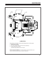
ENGINE COOLING
Continued operation with a clogged cooling system
will cause severe overheating and can result in engine damage.
-
Daily: Clean air intake screen V.
-
Every 100 hours: Clean cooling fins beneath
blower housing H with reference to information in
the engine manufacturer's manual.
SPECIFIC TORQUES
B LADE BOLTS
70 FT-LBS (95 Nm )
WHEEL HUB NUTS
150 FT-LBS (203 Nm)
ENGINE CRANKSHAFT BOLT
50 FT-LBS (68 Nm )
TRANSAXLE PULLEY NUT
28.3 - 41.6 FT-LBS (38 - 56 Nm)
TRANSAXLE DRAIN PLUG
15 - 20 FT-LBS (20 - 27 Nm)
TRANSAXLE FILTER
130 - 150 in-lbs (14.6 - 16.9 Nm)
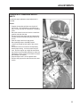
PURGING TRANSAXLES
Due to the effects air has on efficiency in hydrostatic
drive applications, it is critical that it be purged from
the system.
These purge procedures should be implemented any
time a hydrostatic system has been opened to facilitate maintenance or any additional fluid has been
added to the system.
Purging may be required if the unit shows any of the
following symptoms:
28
- Noisy operation.
- Lack of power or drive after short term use.
- High operation temperature, excessive oil expansion.
1. Check the transaxle fluid, fill to proper level, if
required.
2. Raise the drive wheels off the ground. Support
unit with jackstands or other suitable means.
3. With the bypass valves open, and the engine
running, slowly move the control levers in both
forward and reverse directions 5 to 6 times. As
air is purged from the unit, the oil level will drop.
4. With the bypass valve closed, and the engine
running, slowly move the control levers in both
forward and reverse directions 5 to 6 times.
5. Stop engine. Check the transaxle fluid level, add
fluid as required.
6. It may be necessary to repeat steps 3-5 until all
the air is completely purged from the system.
When the transaxle moves forward and reverse
at normal speed, purging is complete.
MAINTENANCE
TRANSAXLES
Inattention to proper safety, operation, or
maintenance procedures could result in personal
injury, or damage to the equipment. Sears
recommends returning the machine to your
authorized Sears Craftsman Professional for
service or repair.
Perform transaxle maintenance with the engine off,
spark plug wires disconnected and PTO disengaged.
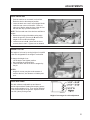
TRANSAXLE FLUID CHANGE
Change the transaxle fluid every 200 hours of
operation. It is essential that the exterior of the
transaxle be free of debris, prior to fluid maintenance.
1. Remove the three 1/4" filter guard screws and
filter guard A. Remove the oil filter B from the
transaxle and discard. Dispose of used oil in accordance with local requirements.
2. Wipe the filter base surface off and apply a film
of new oil to the gasket of the new replacement
filter. Install the new filter by hand, turn 3/4 to
one full turn after the filter gasket contacts the
filter base surface.
3. Re-install the filter guard and torque the three
screws to 65 in. lbs. each.
4. Remove cap C, fill the transaxles through the
expansion tank D with approximately 4 quarts of
SAE 20W-50 engine oil.
Do not overfill! If you overfill the transaxle while the unit
is "cold", it may overflow as it reaches normal operating
temperatures. The oil level should not be above the
manufacturer's suggestions. This will allow the space
needed for the oil to expand as it warms up.
5. After starting engine, check the fluid level and
continue to add oil to overflow tank D to fill line
on tank.
6. Purge the transaxles, following the purging procedures on Page 28.
29
MAINTENANCE
BLADE REMOVAL
BLADE Balance
Follow these instructions to prevent injury during
blade removal:
1. Loosen with a box wrench or a socket and long
breaker bar. To gain additional leverage, slip a
long pipe or thick-walled tube over breaker bar or
wrench.
2. Insert wood block A as shown, with grain
perpendicular to blade, to prevent blade from
turning when loosening.
3. Wear thickly padded gloves. Keep hands clear
of blade path. Blades may rotate when bolt
releases.
Blade balance must be maintained at 5/8 oz-in (19.4
g-cm) or less. Failure to keep blades balanced
causes excess vibration, wear, and shortened life of
most components of the machine.
To balance a blade:
1. Sharpen blade first.
2. Balance the blade at the center.
3. Attach a 1/8 oz (3.9 g) weight at a distance 5"
(127 mm) from center on the light end. This
should make the light end the heavy end:
- If it does, the blade is balanced.
- If does not, file or grind the heavy end until
the addition of the weight makes the light end
the heavy end.
Blade installation
1. Wear thickly padded gloves to prevent cuts from
the sharp blade.
2. Insert the blade bolt, in order, through the conical
washer (cup side toward the blade, as shown),
the blade, and the blade spacer.
3. Install assembly on the blade spindle.
4. Torque the blade bolt to 70 ft-lbs.
Sharpening
Blades may be sharpened by filing or grinding.
- Inspect blades before sharpening.
- Replace bent or cracked blades.
- Replace blades when the lift portion has worn
thin.
o
- Maintain cut angle at 30 .
- Do not overheat blades when sharpening.
- Always use Craftsman Professeional blades.
Use of another manufacturer’s blades may be
dangerous.
30
ADJUSTMENTS
DECK LEVELING
1. Park the machine on a smooth, level surface.
Raise the deck to the transport position.
2. Lower the deck onto a set of equal height blocks
under the rear corners of the deck. Place another set of blocks under the front of the deck so
that the deck top is pitched forward 1/8".
NOTE: The front and rear of the deck are at different
heights.
3. Measure the height of the blade cutting edge
above the ground. Remove pin B and set the
height of cut lever E to that height
4. Loosen nuts on bolts G. Move bolts in slot to
remove slack in chain. Tighten nuts on bolts G.
Height of cut
The height of cut is set by moving height of cut pin B
to the hole designated for the height of cut desired.
To change the height of cut:
1. Lift the deck to the highest position.
2. Move pin B to the selected hole.
3. Lower the deck until the lift lever is stopped by
the pin.
NOTES:
-
Height of cut may vary due to the amount of
tread on the tires, tire diameter or inflation pressure.
DECK RollerS
The deck rollers are adjustable up and down to
provide improved deck flotation and scalping protection at various heights of cut. They are not intended
to ride continuously on the ground. Adjust no closer
than 3/8" (10mm) to the ground.
Height of cut ranges for roller adjustment
31
ADJUSTMENTS
PARKING Brake
NOTE: There are 2 brakes, 1 on each transaxle.
The parking brake should keep the machine from
moving. To check the parking brake, park the machine on a level surface, open the bypass valves and
set the parking brake to ON. Attempt to move the
machine forward and backward by pushing it. If the
machine moves, adjust the parking brake linkage as
follows:
1. Move the machine to a flat horizontal surface.
2. Grip the flats on the brake rod A. Tighten nut
B on the brake rod until you run out of threads.
See Figure 1 for detailed view.
3. Move the parking brake handle to the OFF
position.
4. Loosen nut X.
FIGURE 1
5. Hold brake arm in the OFF position as shown in
Figure 2.
6. Adjust swivel U until swivel stud meets brake arm
hole in the OFF position.
7. Insert cotter pin into swivel U.
8. Tighten nut X.
9. Repeat Steps 1-8 on the opposite side.
FIGURE 2
32
ADJUSTMENTS
HydrostatIC TRANSAXLE adjustmentS
A turnbuckle style hydrostat neutral adjustment is
provided.
Neutral:
1. Support the machine with the rear wheels off
the ground. Use jackstands or equivalent support. Do not rely only on mechanical or hydraulic
jacks.
2. Move the traction levers out into the neutral lock
position and raise the seat.
3. Disconnect the seat switch wire and temporarily
connect the two terminals with jumper wire J as
shown.
4. Start the engine and run at low speed.
5. Move parking brake to the OFF position.
6. Loosen jam nuts K at both ends of the control
rod L.
7. Rotate the control rod until the corresponding
wheel stops turning. Lock the control rod jam
nuts. Run the engine up to high idle and stroke
the traction levers forward and back to check the
adjustment. Move traction levers back to neutral
and readjust if necessary.
8. Repeat steps 6 and 7 for the opposite side.
9. Remove the jumper wire and reconnect the seat
switch.
33
BELT REPLACEMENT
NOTE: Always use Craftsman Professional replacement belts, not general purpose belts.
Craftsman Professional belts are specially designed for use on this mower and will normally last longer.
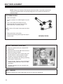
Cutterdeck belt
1. Remove floorplate.
2. Set the cutterdeck in a middle height-of-cut position.
3. Use a 3/8" ratchet and extension to back
tensioning idler off to remove belt from idler.
Remove belt from cutterdeck pulleys.
NOTE: Use the 3/8" ratchet in the square hole A on
the idler.
4. Remove belt from clutch pulley.
5. Install the new belt by performing these steps in
reverse order.
3 SPINDLE DECK
HYDRO TRANSAXLE DRIVE belt
1. Remove cutterdeck belt (see cutterdeck belt
replacement).
2. Disconnect wire I at clutch M. Remove bolts J
and remove torque restraint.
3. Using a ratchet with a 9/16" socket, place over
nut at location P. Use the ratchet to rotate it
enough to remove the transaxle drive belt.
4. Install a new transaxle drive belt by performing
these steps in reverse order.
5. Inspect the fans. Replace if worn or damaged.
Torque transaxle pulley nut to 28.3-41.6 ft-lbs
(38-56 Nm).
6. Reinstall cutterdeck belt (see cutterdeck belt
replacement).
BELT TENSION
All belts are tensioned by spring loaded idlers and do not require any adjustment.
34
Get it fixed, at your home or ours!
Your Home
For expert troubleshooting and home solutions advice:
www.managemyhome.com
For repair – in your home – of all major brand appliances,
lawn and garden equipment, or heating and cooling systems,
no matter who made it, no matter who sold it!
For the replacement parts, accessories and
owner’s manuals that you need to do-it-yourself.
For Sears professional installation of home appliances
and items like garage door openers and water heaters.
1-800-4-MY-HOME®
(1-800-469-4663)
Call anytime, day or night (U.S.A. and Canada)
www.sears.com
www.sears.ca
Our Home
For repair of carry-in items like vacuums, lawn equipment,
and electronics, call anytime for the location of your nearest
Sears Parts & Repair Service Center
1-800-488-1222 (U.S.A.)
www.sears.com
1-800-469-4663 (Canada)
www.sears.ca
To purchase a protection agreement on a product serviced by Sears:
1-800-827-6655 (U.S.A.)
1-800-361-6665 (Canada)
Para pedir servicio de reparación
a domicilio, y para ordenar piezas:
Au Canada pour service en français:
1-888-SU-HOGAR®
1-800-LE-FOYER MC
(1-888-784-6427)
® Registered Trademark / TM Trademark / SM Service Mark of Sears Brands, LLC
® Marca Registrada / TM Marca de Fábrica / SM Marca de Servicio de Sears Brands, LLC
MC
Marque de commerce / MD Marque déposée de Sears Brands, LLC
(1-800-533-6937)
www.sears.ca
© Sears Brands, LLC