1
Combined Conventional / Analogue Addressable
Fire Alarm Control Panel
Operating Manual
Approved Document
1.2May
May2009
2010
MFBU-02 Issue 1.0
NOTE
PLEASE READ THIS MANUAL BEFORE
HANDLING THE EQUIPMENT AND OBSERVE
ALL ADVICE GIVEN IN IT.
THIS PARTICULARLY APPLIES TO THE
PRECAUTIONS NECESSARY TO AVOID E.S.D.
E.S.D.
!
IMPORTANT SAFETY NOTES
The panel is safe to operate provided it has been installed in compliance with the manufacturer’s instructions and
used in accordance with this manual.
Hazardous voltages are present inside the panel—DO NOT open it unless you are qualified and authorised to do
so. There is no need to open the panel’s enclosure except to carry out commissioning, maintenance and remedial
work. This work must only be carried out by competent service personnel who are fully conversant with the contents of the panel’s separate installation manual and have the necessary skills for maintaining this equipment.
This fire alarm system requires periodic checks as specified in B.S.5839 Part 1:2002. It is the responsibility of the
system user to ensure it is regularly serviced and maintained in good working order.
Disclaimer
No responsibility can be accepted by the manufacturer or distributors of this fire alarm panel for any misinterpretation of an instruction or guidance note or for the compliance of the system as a whole. The manufacturer’s policy
is one of continuous improvement and we reserve the right to make changes to product specifications at our discretion and without prior notice. E & O E.
Fusion Operating Manual.
Approved Document No. MFBU-02 Issue 1.2
2
CONTENTS.
Important Safety Notes………...……………………………………………………………..2
Introduction………………………………………………………………………………………. 4
Product Overview……………………………………………………………………………….5
User Responsibilities……...…………………………………………………………………..5
Glossary……………………………………………………………………………………...……..7
Control Panel……...………..……………………………………………………..……………..9
Panel Indicators…………………………………...……………………………..…………….11
Keypad…………………………………….…...…………………….…………………………….12
LCD Display…………………………………………...……...…………………………………13
Menu and Control Functions………...…………………………………….….………...14
Function Buttons……………………………………………………………………...……..14
Access Levels…………………………………………………………………………...….15
Menu Flow Diagram...…………….……………………………………………………..….16
Key to Menu………………………….…………………………………………………..….17
System Operation……………………………...………..……………………………….......18
Fire Alarm………….……………………………………………………………………......18
Silencing the Alarm……………….…………………………………...……………….…..20
Resetting the System…………….…………………………………………………….…..20
Evacuate………………………….…………………………………………………….…...21
Panel Buzzer…………………….……………………………………………………….…21
Fault Conditions………………….…………………………………….…………………...22
Fault Messages………………….………...………………………….…………………....23
Action after a Fire……………….…………………………………….…...…………….…24
Action after a False alarm………….……………………………...……….…………...…25
Action following a Fault………………………………………...………….……………....25
Avoiding false Alarms…………....…….………………….………………..……………...26
Fusion Operating Manual.
Approved Document No. MFBU-02 Issue 1.2
3
INTRODUCTION
The Fusion combines a powerful multi-loop analogue addressable control panel with conventional
and TWIN WIRE technologies and has been designed in accordance with European standards
EN54-2 and EN54-4, Fire Detection and Alarm systems - Control and Indicating Equipment. It utilises
the latest surface mount technology with a flash programmable 32 bit micro-controller for easier
software updates.
The panel operates with Apollo Fire Detectors, XP95 & Discovery analogue addressable protocols
and also supports the Apollo and Hochiki ranges of conventional field devices. Four internal sounder
circuits are provided in the base unit, with an additional two circuits per loop card. Extra sounder
circuits can be provided with the use of modular PCBs.
The control panel is programmable via the keypad controls or via a PC or laptop, allowing the
configuration to be created off-site and uploaded.
In addition to the requirements of EN54-2 the control panel has the following facilities:Test Condition, to allow the automatic resetting of zones in alarm for testing purposes. EN54-2
Section 10, option with requirements.
Outputs to Fire Alarm Devices, to enable an audible warning to be sounded throughout a premises
upon the detection of a fire condition or the operation of a manual call point. EN54-2 section 7.8,
option with requirements.
Output to Fire Alarm Routing Equipment, monitored signal for use with remote, manned stations
etc. EN54-2, section 7.9.1, option with requirements.
Delays to Outputs, programmable delays to outputs can be configured. EN54-2 section 7.11, option
with requirements.
Note: If these delays are configured, a manual call point must be installed near the panel for the
purpose of overriding the delay.
Disablements of Addressable Devices, EN54-2 section 9.5, option with requirements
Fault signals from points, EN54-2 section 8.3, option with requirements
Also in addition to the requirements of EN54-2, all control panels have voltage free relay contacts for
faults and fire These are to be used for local control and signalling.
The Fusion has individually isolatable panel contacts via the menu with an auto enablement feature
and the option to remove all disablements. The menu is comprehensive, yet easy to use, allowing
electrical isolation of the loop via the keyboard. The menu also includes an enhanced test mode, with
or without sounders allowing all zones to be tested simultaneously if required. It has a real time
clock, with back up, utilising a smart cap rather than a battery, thus eliminating battery life issues.
The Fusion incorporates a very fast auto learn sequence, only learning selected parts of the loop,
and if required can unlearn devices from the system. It supports the Apollo ancillary base sounders
and relays, local, zonal or common operation. A device monitoring mode allows activation of the
device outputs and control of the loop polling direction. Also there is a selectable maintenance
scanning threshold.
The Fusion has genuine peer to peer panel networking, utilising reliable CAN bus technology, with
response settings to evacuate,1st alarm, 2nd alarm, precinct and fault signals, with programmable
responses for loop sounders, panel sounder circuits, remote relays and loop modules.
This User's manual explains the operation of the panel and incorporates a user's responsibilities
guide for testing and maintaining the system. It is intended that the user's manual with the log book
forms part of the documentation package passed to the customer on completion.
Fusion Operating Manual.
Approved Document No. MFBU-02 Issue 1.2
4
PRODUCT OVERVIEW
The control panel is combined multi loop, up to 64 zone, analogue addressable and / or conventional
unit with integral power supply and space for standby batteries. It has two additional sounder circuits
per loop card as well as, auxiliary volt free contacts and various remote inputs and outputs. Also 32
soft groups are provided for cause and effects configuration, per loop or conventional radial card.
The control panel comprises a sheet steel enclosure suitable for wall mounting with a hinged,
lockable front access door. It can be semi-recessed if required by using a suitable flushing bezel.
Cable entry is via the top or rear of the cabinet, where 20mm 'knockouts' are provided.
Different key types are used for the door lock and the ‘enable' key-switch, to control levels of access.
A 2 x 40 character, backlit LCD is fitted to display event information and function or configuration
menus. Alarm and status information is provided by LED indicators and there is a 12 button keypad
which controls the system and allows access to the function and configuration options.
The Fusion panel is provided with an internal power supply module. The smaller FBUS models have
a 3 Amp module and the FBUL versions have a 5 Amp module. These modules Comply with the requirements of EN54-4 :1988 and provide temperature compensated battery management, charging
and earth fault monitoring. The power supply modules consist of an assembly comprising AC mains
to 36vdc power pack and a control PCB with heat-sink which provides the control and monitoring
functions and 28vdc nominal power output. The power supply modules have two independent current
limited outputs for supplying power to the panel circuits.
Both power supply units are designed for use with VLRA sealed lead acid type batteries see Installation manual for details of battery models and sizes. These rechargeable batteries provide power in
the case of a loss of AC mains power.
It is possible to power the panel from a remote power supply if required and input terminals are
provided to facilitate the remote supply input and also to monitor the unit for mains and battery
failure.
Access to the panel functions and configuration options is at different levels enabling restricted
access to certain functions. At the user level it is possible to disable parts of the system, set the time
and date, put the system into walktest mode and view the system status. Advanced options include
configuration, maintenance checks and fault finding mode.
The control panel incorporates an 'auto-learn' feature which enables the system devices to be
recognised on initial power up. Configuration of the system operation can be achieved via the panel
controls or by downloading data created in a PC software program.
USER RESPONSIBILITIES
BS5839-1: 2002 is the British Standard code of practice for the design, installation, commissioning
and maintenance of fire detection and fire alarm systems for buildings. Section 7 of the standard
(User Responsibilities) states that a named responsible person should be appointed to supervise all
matters pertaining to the fire alarm system {clause 47.2a}.
Highlighted below is a summary of the main functions the responsible person is expected to carry out
with regard to BS5839-1: 2002 only. It does not highlight any other responsibilities that may be required of the user or responsible person that are listed in documentation such as the Employees
Guide to Fire Safety, the Fire Precautions (Workplace) regulations and/or any other legislation relevant to the premises. If in doubt, the fire authority can advise on the fire legislation that applies to any
given building. For countries outside the UK, different user responsibilities may apply.
Fusion Operating Manual.
Approved Document No. MFBU-02 Issue 1.2
5
USER RESPONSIBILITIES continued
BS5839-1: 2002 states the responsible person should:
(The bracketed numbers {xx} identify the BS5839-1: 2002 clauses to which the summary refers).
1.
Ensure the fire alarm panel is checked daily to confirm there are no faults on the system
{47.2b}
2.
Ensure arrangements are in place for the test, maintenance and regular servicing of the system with regard to Section 6 of the standard {47.2c}. Important: Clause 44 of BS5839-1: 2002
recommends weekly and monthly tests that should be carried out by the responsible person.
See below for details.
3.
Ensure the system log book is kept up to date by recording fire signals, fault signals, work on
the system, etc and make sure it is available for inspection at all times {47.2d / 48}
4.
Ensure all relevant occupants of the premises are instructed in the proper use of the system
{47.2e}
5.
Take steps to limit the number of false alarms on the system {47f}
6.
Ensure the effectiveness of the system is not impaired by ensuring there is a space of at least
500mm in all directions around and below every fire detector and that all manual call points are
unobstructed and easy to see {47g}
7.
Liaise with all relevant building engineers, decorators, etc, to ensure any changes to (or maintenance of), the buildings fabric does not compromise the protection given by the fire alarm
system, create faults or false alarms {47h}
8.
Ensure that any structural or occupancy changes planned for the building are done so with due
and early consideration given to any changes that may be required to the fire system {47h}
9.
Ensure that a selection of spare parts are held as appropriate within the premises {47j}
Routine weekly and monthly testing to be undertaken by the user / responsible person
To meet the requirements of Clause 44 of BS5839-1: 2002 we recommend the following tests are
carried out at approximately the same time each week, during normal working hours:Note: It is essential any alarm receiving centre is contacted before and after these tests to avoid unwanted alarms and to confirm the fire signal is correctly received.
•
Carry out an indicator lamp test to check all zone lights show and the buzzer sounds.
•
Operate a manual call point or smoke/heat detector to test the fire alarm.
•
Check that the alarm sounders operate
•
Reset the system by pressing the Silence/Activate Sounders button and Control Panel Reset
button.
•
Verify that no manual call points or smoke/heat detectors are obstructed in any way.
•
Test a different zone each week using a different call point or detector so all are tested in rotation.
Monthly attention: Ensure authorised service personnel verify the system’s standby power supply
(or supplies) are in good working order.
Quarterly and periodic inspection, testing, servicing and maintenance
It is the user’s responsibility to ensure that an ongoing periodic plan is in place that meets Clause 45
(Inspection and Maintenance) of BS5839-1: 2002. The work required to meet this Clause must be
carried out by a competent person with specialist knowledge of fire detection and alarm systems. The
standard recognises this will normally be an outside specialist fire alarm servicing organisation.
Please note: the above summaries do not replace Sections 6 and 7 of BS5839-1: 2002 but are intended to help the user gain a greater understanding of his or her
responsibilities. We strongly recommend the named responsible person familiarises themselves with the full standard, copies of which are available from your local
reference library or can be purchased from the British Standards Institute, Customer Services Dept., 389 Chiswick High Road, London, W4 4AL..
Fusion Operating Manual.
Approved Document No. MFBU-02 Issue 1.2
6
GLOSSARY
Address
An address is the unique identification applied to each field device in an addressable system
Addressable system
An addressable system is one where each field device has an address which can be identified and
displayed in an abnormal condition or for normal monitoring purposes. The address is normally
accompanied by a user-defined text message describing the device location, e.g. 'First floor corridor'.
Addressable devices are usually wired in a loop configuration.
Analogue/addressable system
In addition to device addressability, the detectors employed are analogue devices transmitting data
to the control panel which is then analysed and processed so that the appropriate condition can be
displayed. Analogue systems can provide greater immunity to false alarms and give advance
information about impending fire conditions.
Automatic system
An automatic system is one which includes detectors of some description, as opposed to one fitted
with manual call points only.
Conventional System
This is a system which uses ‘non addressable’ field devices. Up to 32 devices may be connected to a
single circuit. When an alarm occurs a search of this circuit has to be undertaken to identify the device in alarm
Device
A component of an addressable system connected to the loop circuit. It can be an input device such
as a detector or call point, or an output device such as a relay or sounder controller. Devices in an
addressable system are uniquely numbered and there is a maximum of 126 devices which can be
connected to a single loop.
Detector
A device which detects either flame, smoke or heat. Analogue detectors are often referred to as
sensors because of their ability to transmit variable data to the control panel.
Disabled
The condition of the system when part or parts of it have been isolated for any reason. It is possible
to disable individual addresses, complete zones and/or remote outputs. The normal condition is
'enabled'.
Field device
See Device
Fire procedure
A written procedure describing the actions to be taken in the event of a fire alarm. Procedures should
also include the actions required after a fire and in a fault condition. All staff should be conversant
with the fire procedures.
Input/output (I/O) device
A device which either monitors a remote function or provides a signal to control a remote function, or
both. Used with analogue/addressable systems to interface with other services. Each I/O unit has an
address.
Fusion Operating Manual.
Approved Document No. MFBU-02 Issue 1.2
7
GLOSSARY continued
Loop
The method of wiring an addressable or analogue/addressable system whereby the circuit
connecting the devices is wired from the panel and is returned to the panel to form a loop. With this
method a break in the loop circuit, although indicated as a fault, does not disable the operation of any
devices.
Manual call point (MCP)
Also known as a break glass unit, initiates a fire alarm condition when activated. MCPs comprise a
standard call point assembly fitted with an input module on analogue/addressable systems, and have
a unique address.
Radial
A term to describe a conventional detection or sounder circuit which is terminated with an end of line
resistor.
Sensor
See Detector
Short circuit isolator (SCI)
A device connected to the loop circuit which limits the loss of devices in a short circuit condition.
They are generally fitted between each zone to restrict the loss of detection to one zone in
accordance with BS 5839 Part 1. SCIs do not have an address and do not limit the number of
devices on a loop.
Sounder
A device which provides an audible warning of a fire alarm condition. Sounders may be bells but are
often electronic devices with a range of sound options and volume control. In most systems the
sounders must achieve a minimum level of audibility throughout the protected premises.
System type
Systems complying with BS 5839 Part 1 are classifed depending on the application. There are two
main categories, i.e. Life Protection (L type) and Property Protection (P type). Each category is subdivided depending on the level of protection required for the particular risk.
Zone
A zone is the sub-division of a building separated by fire resisting walls to form a compartment. When
applied to a fire alarm control panel it refers to the number of fire indicators available to identify the
location of a fire within a building. Each fire compartment generally comprises one or more zones.
Each floor of a multi-storey building is a separate zone, and each vertical structure (staircase,
liftshaft, etc.) is a separate zone. Smaller zones may be required in areas of high risk. In an
analogue/addressable system the zonal indicator denotes the general area of the fire whilst the LCD
indicates the actual activated device.
Fusion Operating Manual.
Approved Document No. MFBU-02 Issue 1.2
8
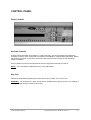
CONTROL PANEL
Panel Controls
Activate Controls
Controls maybe activated via keyswitch or 4 digit code entry. Use of the keyswitch precludes the
necessity to enter a code. Limited menu functions are available for viewing status information without
the need for keyswitch or code entry. See menu and control functions section of this manual for
further information.
If the keyswitch is turned to the ON position then the keypad becomes fully functional.
NOTE : It is not possible to withdraw the key in the ON position.
Key lock
This allows authorised engineering personnel access to the inside of the control unit.
WARNING : The power to the alarm unit should be isolated before gaining access. The voltages in
this unit are high enough to cause severe injury.
Fusion Operating Manual.
Approved Document No. MFBU-02 Issue 1.2
9
CONTROL PANEL continued
General description
The control panel comprises a sheet-steel wall mounted enclosure with a lockable hinged door. All
the user controls and indicators are mounted on the fascia of the unit - there are no user controls
within the panel.
Normal Operation
In the normal operating mode only the green Supply Healthy LED (light emitting diode) should be
illuminated. The LCD (liquid crystal display) should be showing the current time, date and company
name, if programmed. Other indications that may show in normal operation are:
1.
System normal – Controls are not active, limited menu available
2.
Controls Active- If key-switch is in the ‘on’ position
3.
Delayed – (LED) is displayed if any output delays are programmed
4.
General Disablement – (LED) also shows ‘disablements active’ (LCD) displayed if any zones
or devices have been disabled, details of disablements can be viewed in ; Menu item / View
active disablements
5.
Test mode – (LED) will show if engineer test mode has been set to areas on the system. Test
mode should only be used by authorised personnel
6.
Precinct Active - (LCD) remote input to activate alarm sounders is active (often referred to as
class change)
7.
Alert Active –(LCD) remote input to pulse alarm sounders is active
8.
Delays are Inactive – (LCD) – programmed delays have been set to ‘off’
Fire Alarm Event
A fire alarm event is caused by the activation of a field device. It may be generated automatically by
a smoke or heat detector sensing smoke or heat, or manually by the operation of a call point. In
either case it will cause an audible alarm to be given (usually throughout the building) and the event
details to be displayed and indicated on the control panel.
NOTE . Each system is individually configured for the required operation. Space is provided in the
manual to record the method of operation of this system, which should be completed by the installer.
The prescribed emergency fire alarm drill should commence immediately the alarm is heard (see
System Operation)
Fault Event
A fault event is generated when the control panel detects an internal malfunction or a fault on an
external circuit or device. A fault is indicated by the relevant LED/s and the buzzer sounding. A fault
description is shown on the LCD. Additional information about the fault may be obtained by pressing
button [ 1 ]
Control Event
A control event is caused by the operation of one or more of the keyboard pushbuttons. All controls
are inoperable until the 'Controls' keyswitch is set to the 'on' position, or alternatively a code number
entered to prevent unauthorised operation. A keypad is provided to silence and reset the system
following a fire or fault event, initiate an evacuation alarm, and to access the menu functions.
Fusion Operating Manual.
Approved Document No. MFBU-02 Issue 1.2
10
PANEL INDICATORS
Fire
Indicates the presence of a Fire Alarm signal or an Evacuate command. Flashes red when there is a
fire and goes steady when alarm is silenced. Subsequent alarms will re-start the flashing.
Test Mode
Indicates system is in the Engineers Test mode.
General Disablement
Indicates that part of the system is disabled (isolated)
Supply Present
Indicates that the Mains or Battery supply is present.
General Fault
Indicates that a fault is present on the system. The LCD will show the details.
Pre-Alarm
Indicates that a detector has recorded a higher than normal analogue value which could signal an
impending fire condition.
Delayed
Lit when one or more output delays have been programmed. Flashes when one or more output
delays are running.
Sndr Fault / Disabled
Indicates a fault on the alarm sounder circuit. Sounder devices / circuits may be faulty or disabled.
Fire alarm routing output active
Designated output to inform monitoring service is activated.
Fire alarm routing output disabled/ faulty
Designated output to inform monitoring service has been disabled or has a fault condition.
System Fault
Indicates that the processor has halted. This can only be reset by manual operation at access level
2. Will remain on even if the system has automatically re-started
More Events
Indicates that there are more events. Scroll to view them
Power Fault
Indicates power supply failures. The LCD will show the details.
Fire Detection Zones
Up to 64 indicators (Zones 1-64) to show which area (group of devices) has activated in a fire
condition. LED will flash for new zone in alarm and become steady when alarm is silenced.
Fusion Operating Manual.
Approved Document No. MFBU-02 Issue 1.2
11
KEYPAD
All the numbered keys are digits in their own right but also have the following additional functions:-
[ 1 ] Press for more information about an active device
[ 2 ] Scroll up
[ 3 ] Generate full alarm (evacuate)
Override active delay( if a delay is running)
[ 4 ] Scroll left
[ 5 ] Select to view option or Enter
[ 6 ] Scroll right
[ 7 ] Mute internal fire/fault buzzer
[ 8 ] Scroll down
[ 9 ] Toggle: silence/re-sound alarm.
Halt active delay / restart delay (if a delay is running)
[0]
[ MENU ] Access to menu
[ ] (Bottom right) Control panel reset
Fusion Operating Manual.
Approved Document No. MFBU-02 Issue 1.2
12
LCD DISPLAY
The LCD displays event information, status information, and the option menus. It has two lines of
text, each with 40 characters , and is backlit when there is an active event on the system or the
menu options are accessed. In the normal operating mode the backlight is dim and the top line
displays a default text message or user-defined text. The second line displays the current time
and date, e.g.
FUSION PANEL
SYSTEM NORMAL
9:36 15/03/04
When an event occurs, the backlight is activated and the LCD shows the event details, e.g.
FIRE
ZONE 01 OK 01 Z0NES
01 OF 01
PANEL 01
RECENT ZONE 01
The display shows the event type, i.e. Fire, the zone that the activated device is in, i.e. zone 3, the
number of events, i.e. 1. The bottom line alternates with the device location text (if programmed)
Pressing button [1] reveals the device information, Type, i.e manual call point, address number
and time and date of the event. This button will function regardless of status of keyswitch.
NOTE : Fault conditions on the system are suppressed when Fire events are present. The
SYSTEM FAULT LED is illuminated and faults can be viewed if required via the 'View Active
Faults' option - when button [1] is pressed.
The bottom line displays a text message describing the device location.
In the menu mode, menu options are displayed as follows:
SELECT MENU OPTION
5 — TEST LAMPS
The Keypad is used to navigate through the menu options and select functions as described in
the installation and commissioning manual.
Fusion Operating Manual.
Approved Document No. MFBU-02 Issue 1.2
13
MENU AND CONTROL FUNCTIONS
General
The control panel incorporates facilities to alter the status of the system, e.g:- it is possible to isolate
parts of the system if there is work in progress, or a particular device is faulty and causing unwanted
alarms. The system can be put into test mode to allow an engineer to activate devices without
causing a general alarm, and the time and date can be changed, e.g. for British Summer Time.
These functions are accessible to the user at access level 2 but care should be exercised when
utilising the functions as it is possible to disable some or all of the system. It is recommended that
before attempting to enter the options menu the features are fully understood, and the operator is
familiar with the controls used to navigate the menus and select options.
Function buttons
Four of the keypad buttons are used as function buttons when the options menu is invoked.
Most of the panel functions, including configuration, are controlled by these buttons which have the
following functions:[MENU]
The Menu button is used to initially invoke the options menu. Press once to enter the Menu , and
press again to Exit.
[2] and [8]
The 2 and 8 buttons are used to move to and then select the Menu options. Once an option has been
selected, the Menu button should be pushed again to exit.
[5]
The 5 button on the keypad is pressed when the option selected needs to be viewed, or to view the
text or an active event.
[4] and [6]
The 4 and 6 buttons are used to position the cursor along a full display line in order to adjust various
options available.
Fusion Operating Manual.
Approved Document No. MFBU-02 Issue 1.2
14
MENU AND CONTROL FUNCTIONS continued
Access levels
To prevent unauthorised operation of the panel controls and functions, access is restricted in
accordance with the requirements of EN54 -2.
The following access levels apply:Level 1
Accessible without keyswitch or code entry. Full restrictions.The internal buzzer MUTE
only is available at this level and Scroll and Select if ‘Fire’ is active.
Note: The large cabinet version of the panel has a door with a clear acrylic window
which must be opened to gain access to Level 1. If delays are used then a call point
must be fitted next to the panel to allow override of the delay.
Level 2
CONTROL keyswitch ON, or code entered. The control switches are operable and
menu level 2 fuctions available.
Level 3
An access code must be entered to gain access to the configuration and advanced
options. An additional switch operation is required at engineer level to access
configuration data.
Level 4
Configuration software. Download facilities are available for off-site programming.
NOTE :Amending the system configuration can have serious effects on the operation of the
equipment and should only be undertaken by a competent person who has information concerning
the devices installed and the specified operational requirements.
The system should be fully tested after any alterations to the configuration
program.
Menu Procedures
The following procedures are common to all of the menu options and should be understood before
attempting to alter the system status.
Press the [MENU] button on the KEYPAD to display the following :-
* SELECT MENU OPTION *
2. VIEW ACTIVE FAULTS
Use the [2] and [8] keypad buttons to toggle (scroll) to the required option, then press [5] to display
the required information.
At any time, pressing [MENU] again will return you to the menu options, or in some cases return you
to the last step.
Depending on the option selected, there will be sub-menu items which can be accessed by the [5]
key or scrolled across to, using the [4] and [6] keypad buttons.
When satisfied with the data obtained, press [MENU] to return to the initial screen.
Fusion Operating Manual.
Approved Document No. MFBU-02 Issue 1.2
15
MENU AND CONTROL FUNCTIONS continued
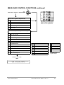
OFF
Press ‘Menu’ button on keypad
OR
ON
ACTIVATE
CONTROLS
Access Level 1 (open to all personnel)
1
Enter access level 2 (enter access code 5839)
2
View active faults
3
View active disablements
4
View event logs
5
Test lamps
Menu Button = Enter / Exit option
Button [5] select or toggle option
Buttons, 2,4,6,8, navigate menu
Access Level 2 (authorised personnel only)
2
View active faults
3
View active disablements
4
View event logs
5
Test lamps
6
Clear event logs
7
Set disablements
1
Set relays disablement
1 Relay #1
8
Set clock
2
Set sounders disablement
2 Relay #2
9
Activate test mode
3
Set loop isolate
3 Set remote isolate *
4
Set zones disablement
4 Common fault
5
Set radial/loop device disablements
5 Loop modules
6
Set auto enables
7
Remove all disablements
10 Print options
11 Set delays
12 Enter access level 3
* Dependant upon
program settings
Enter access code
xxxx
Access level 3 (for service personnel only)
Refer to Installation Manual
Fusion Operating Manual.
Approved Document No. MFBU-02 Issue 1.2
16
MENU AND CONTROL FUNCTIONS continued
Key to menu.
2.
View active faults.
This option provides a method of viewing faults on the system when there are active fire
events present.
3.
View active disablements.
This option allows the user to identify parts of the system that have been isolated.
4.
View event logs.
This option allows the Alarm log, Fault log and the User log to be inspected.
5.
Test lamps
6.
Clear event logs
7.
Set disablements.
This option allows remote outputs, sounders, loop and zones to be disabled and also enabled
manually or automatically at a preset time and date.
•
Remote Contacts can be disabled or enabled for test purposes. This applies to relay 1, relay 2,
common fault or the loop module relays.
•
Sounders can be disabled if required and enabled again.
•
The Loop can be isolated on this option.
•
Any selected zone can be disabled or enabled.
•
Any of up to 126 devices on the loop can be disabled or enabled.
•
Timers can be set for devices or outputs, to be re-enabled automatically at a specified time
and date with this option.
•
All disablements, on whatever device or line, can be cleared simultaneously
•
A programmable option is available to use a switch monitor or input module to isolate predetermined groups of devices. This is set up via the cause and effects parameters.
8.
Set clock.
Allows the time and date to be entered via the keypad.
9.
Activate test mode.
Allows zones to be tested individually or all together. With or without sounder. An optional
managers code can be used to allow access to this function.
10.
Print options (if printer is fitted)
11.
Set delays (if delays are programmed)
Switches delays ‘off’ or ‘on’
12.
Enter access level 3 (Engineering Options)
In order to access the Engineering options a security code is needed which is normally
restricted to engineering personnel only.
All the details of the Engineering Options and the options that allow the system to be reconfigured with the relevant flow charts can be found in the Installation and Commissioning
Manual.
Fusion Operating Manual.
Approved Document No. MFBU-02 Issue 1.2
17
SYSTEM OPERATION
Fire alarm.
During normal operation the only active indication on the control panel is the green Supply Healthy
LED. The LCD shows the system normal message and the time and date. The backlight may be
dimmed slightly.
The control keyswitch should be in the OFF position and the key should be removed and stored in a
secure place, readily available when required.
If a manual call point is activated, or an automatic detector senses smoke or heat, a fire alarm signal
is generated and the following occurs:
1
The alarm sounders operate in accordance with the programmed configuration. This is
normally a general evacuation (continuous) alarm throughout the building, but may be an alert
(intermittent) signal, or alarm in certain parts of the building only.
2
The common FIRE LED flashes on the front panel.
3
The relevant zone LED flashes (1-64).
4
The LCD illuminates and shows the event information.
5
The internal buzzer pulses rapidly.
6
The remote contacts operate and signal the fire brigade (if this has been
configured in the system.
7
Remote control functions are initiated in accordance with the program, e.g.
doors closed, ventilation shutdown, etc.
8
Event details are printed (if a printer is fitted).
9
SMS text messages are sent (if FIRETEXT module is fitted)
The actions to be taken in the event of a fire alarm should be fully documented and implemented
immediately upon hearing the alarm.
In the event of a fire condition on multiple zones:•
The panels general fire indicator will flash, it’s internal sounder (if enabled) will pulse and it’s
relevant fire zone indicators will flash.
•
The panel’s display will show the first and last zones that went into fire together with the total
number of zones that are in fire. For example, if a fire condition has occurred in zones 1,2 and
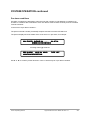
3 in that order, the display will show a message similar to the one below.
•
The system’s sounders, relays and other output devices will operate as programmed.
First zone in alarm
FIRE ZONE 01 OF 03 ZONES
01 OF 03
PANEL 01
RECENT ZONE 05
Fusion Operating Manual.
Sequence of total qty of alarms
Last zone in alarm
Approved Document No. MFBU-02 Issue 1.2
18
SYSTEM OPERATION continued
To view any additional zones that are in fire, press the ▲or ▼ buttons, as appropriate. The display
will continue to show the last zone that went into fire but all previous zones will now appear on a
step-by-step basis with details of which order they went into fire, i.e. 1st zone, 2nd zone, etc.
Pressing the more information button [1], at any time will give you details of the actual device(s)
that are in a fire condition on the zone that is on the top line of the display. These can be scrolled
through using the ▲ and ▼ buttons.
!
In the event of a fire condition, the building’s fire management plan should always be
executed.
Authorised users can silence or reset the system as appropriate by entering access level 2 and
pressing the buttons on the panels front. Details on how to do this can be found on page 23
After the event, note the event details, i.e. the activated zone and the device details if not already
determined.
Fire alarm with output delays
The system can be programmed with delays to outputs (fire alarm sounders). If a delay has been
programmed this is indicated by the DELAY LED which will be illuminated. Delays can be applied to
all zones or individual zones as required.
A programmed delay can be turned off if required in the menu option 11: Set delays.
If a delay is turned ‘OFF’ DELAYS INACTIVE will be displayed alternately on the normal display. If
the delay is set ‘ON’ the DELAY LED will be illuminated.
If the acknowledgement and investigation delay option is enabled. A fire alarm is registered at the
panel but does not immediately activate the sounders or remote output (dependant on program
settings). The display will show:[FIRE /DELAY 019 ZONE 01 OF 01 ZONES ACK TIME]
[40 CHARACTERS LOCATION TEXT]
The delay timer shows how much time is left for acknowledgement. If the alarm is not acknowledged
before the first timer expires the panel will enter full alarm
The alarm can be acknowledged by pressing button [5] on the keypad. If the sounders are active
they may be silenced by pressing SILENCE / RESOUND ALARMS button.
Once acknowledged the display will show:[FIRE /DELAY 120 ZONE 01 OF 01 ZONES INVEST]
[40 CHARACTERS LOCATION TEXT]
The delay timer shows how much time is left for investigation. If the alarm is not RESET before the
second timer expires the panel will enter full alarm..
Pressing EVACUATE or operating a manual call point will terminate the investigation delays and
activate all programmed sounders.
Fusion Operating Manual.
Approved Document No. MFBU-02 Issue 1.2
19
SYSTEM OPERATION continued
Pre alarm conditions
Pre-alarm conditions are designed to warn the user that a smoke or heat detector is registering an
increase in conditions that could lead to a fire. Pre-alarms must be taken seriously as a fire condition
could be imminent.
In the event of a pre-alarm condition:The panel’s internal sounder (if enabled) will pulse and the Pre Alarm LED will be lit
The panel’s display will show details of the zone which is in pre alarm, for example:
001 FAULTS IN ZONE 01
01 OF 01
PRESS [1] FOR DETAILS
Pressing button [1] will show
PRE ALARM LOOP 01 A018
LOCATION DESCRIPTION
TYPE OPT
Use ▲ or ▼ to scroll any further devices in zone 01 which may be in pre-alarm condition.
Fusion Operating Manual.
Approved Document No. MFBU-02 Issue 1.2
20
SYSTEM OPERATION continued
Silencing the alarm
Before the alarm sounders can be silenced, or any other control function activated, the ACTIVATE
CONTROLS keyswitch must be set to the ON position by inserting the key and turning it clockwise a
quarter of a turn. Alternatively if the option has been set, a code entry will activate the controls. The
access code for level 2 is +5839
With the controls enabled, press the SILENCE/RESOUND ALARMS keypad button once:1
2
3
4
5
The alarm sounders on the system are silenced.
The LCD will illuminate to indicate the current status.
The flashing common fire and zone LEDs change to steady.
The buzzer tone changes to an intermittent bleep.
The LCD continues to show the event information.
NOTE : If another device is activated, the sounders are re-energised and the new event information
is displayed.
If there are multiple events on the system, the information for each event may be viewed by using the
toggle function with keypad buttons [2] and [8].
The ‘MORE’ LED is illuminated if there are other events. The LCD shows the total number of events.
Resounding the alarm
If, having silenced the sounders, it is necessary to reactivate them, e.g.because there are still
personnel within the building, press the SILENCE/RESOUND ALARMS keypad button again.
Resetting the system
To restore the system to normal operation after a fire alarm it is necessary to
reset the control panel by pressing the RESET button.
All the LEDs illuminate for 3 -4 seconds (lamptest function) following which
the panel reverts to its normal mode.
NOTE :
1
It is not possible to reset the system until the alarms have been silenced.
2
The system will not reset if the cause of the alarm is still present, i.e. broken glass in call point
or smoke/heat in the vicinity of a detector.
Fusion Operating Manual.
Approved Document No. MFBU-02 Issue 1.2
21
SYSTEM OPERATION continued
Evacuate
The EVACUATE button, keypad [3], may be operated at any time to activate the alarm sounders.
The CONTROLS keyswitch must be in the ON position or code entered.
Press the EVACUATE button once:
The sounders are energised and the common FIRE LED will flash.
To turn the Evacuate signal off:
Press the SILENCE button, keypad [9] (This will be displayed on the LCD and the flashing ‘FIRE’
LED will change to steady).
Press RESET button (bottom right on keypad)
Panel buzzer
The internal panel buzzer operates whenever an abnormal event is on the system.
Iit operates in the following modes:
Fire / Evacuate
Fast Pulse
Fault
Slow Pulse
Disablement
Double Pulse
Silenced
Intermittent Bleep
This buzzer may be muted without affecting the alarm device status by pressing keypad button [7]
Monitoring
The control panel internal circuitry is fully supervised in accordance with the requirements of EN542-1998 and indicates a failure as a fault condition. Loop and sounder circuits are monitored for open
circuit and short circuit fault conditions. Essential fuses are monitored.
Fusion Operating Manual.
Approved Document No. MFBU-02 Issue 1.2
22
SYSTEM OPERATION continued
Fault conditions
When the control panel detects a fault condition one of the following occurs:
1.
The GENERAL FAULT LED will flash and the display will show the details.
2.
The PRE-ALARM led will flash. This indicates that a detector has recorded a higher than
normal analogue value which could signal a possible fault with that detector, or an impending
fire condition. The display will show the details.
3.
The SYSTEM FAULT led will flash, indicating that the processor has halted. This can only
be reset by an engineer.
4.
The SNDR FAULT led illuminates to indicate a fault on the alarm sounder circuit.
5.
The PSU led, when lit, indicates a power supply failure. The LCD will show the details
6.
For each of the above or combination of them, the internal buzzer pulses (slow pulse)
7.
The LCD will display the event information, e.g.
001 FAULTS
IN ZONE 03
PRESS [1] FOR DETAILS
01 OF 01
The fault message is normally self-explanatory, for instance, in the above example the message is
FAULT IN ZONE 03. The fault condition can be accepted by pressing the SILENCE key [9]. To
view the text description of the device press keypad button [5].
The flashing LEDs go steady and the buzzer tone changes to an intermittent bleep. The panel
automatically returns to normal operation when the fault condition clears; however, certain faults,
e.g. SYSTEM FAULT, require the CPU (central processing unit) to be reset.
Fusion Operating Manual.
Approved Document No. MFBU-02 Issue 1.2
23
SYSTEM OPERATION continued
The following list describes the typical fault messages. Any fault that does not have a logical
explanation should be immediately reported.
WARNING : High voltages are present within the panel which could cause fatal shock. The front
door should only be opened by a competent engineer. There are no user serviceable
parts inside the panel.
IF IN DOUBT - CALL AN ENGINEER
Fault messages.
The following events are detected and reported :Message
Fault Condition
Det. removed
Conventional detector removed
No response
Addressable device removed
Type error
Device fault / wrong device type installed
Loop open circuit
Loop circuit open
Loop short circuit
Loop circuit short
Power supply fault
PSU failed
Sounder short / open
Open / short circuit on sounder circuit
Radial short / open
Open / short circuit on conventional circuit
Mains fail
Mains failed
Battery fault
Battery disconnected (max 30s delay)
Supply calib.mode
Power supply set to calibration mode
Earth fault
Earth fault
Output limit 1/2
Power supply path output 1 or 2 shorted
Double response
Duplicate address
CPU fault
CPU failed
Network
Communications failure
Charger fault
PSU failure (external only)
Voltage fault
28 volts outside spec. (<22v, >30v)
Device fault
Analogue value low
Warning - Prog switch ‘on’
SW 6 on DIL switch set to ‘on’ or switch 1 on
additional loop / radial boards.
Bad response
Loop data corruption
Ancillary relay fault
Ancillary sounder fault
A device is unplugged from an ancillary unit
which relies on it for operation
GPRS fault (xxxx)
Message to SMS provider was not sent (if
FIRETEXT module is in use) (xxxx) refers to
unique fault code.
Fusion Operating Manual.
Approved Document No. MFBU-02 Issue 1.2
24
SYSTEM OPERATION continued
Action after a Fire
The following actions are in compliance with EN54-2
The responsible person should ensure that the following work is carried out as soon as possible after
any fire, and that normal use of the area is not resumed until the work is complete.
a)
If the system includes detectors containing radioactive material (ionisation type), then special
precautions may be required and the servicing company should be consulted.
b)
Each device which may have been affected by the fire should be tested.
c)
Each fire alarm sounder should be tested.
d)
A visual examination should be made of areas which might have been damaged by the fire,
including power supplies, control equipment and interconnections.
e)
Any defect found should be recorded in the log book and immediate action taken to rectify the
defect.
f)
The servicing company should be advised and instructed to carry out a check of the system.
The responsible person should also ensure that the following work is carried out, although this can
take place after normal working has resumed.
a)
A check should be made of the state of the battery (ies) and charger.
b)
The servicing company should be instructed to carry out a full inspection and test of the
system to verify its operation. This may include cables which are buried and areas that may be
hidden.
c)
If the fire was not detected by the system, or the response was unacceptably slow, then the
reasons for this should be investigated and a report obtained. Consideration should be given
to modifying or upgrading the system if necessary.
On completion of the work a certificate should be obtained.
Fusion Operating Manual.
Approved Document No. MFBU-02 Issue 1.2
25
SYSTEM OPERATION continued
Action after a false Alarm.
Any alarm from the system should be treated as an alarm of fire until it can be proved to be
false. False alarms can lead to a loss of confidence in the system and the responsible person should
take steps to minimise the risk of such occurrences.
There are prescribed levels for the rate of false alarms and if this level is exceeded the responsible
person must instigate special attention to resolve the problem.
The average number of false alarms from an installation should not exceed one false alarm per year
for each 25 detectors.
The following actions should be taken following a false alarm:a)
Where possible, identify the device which has initiated the alarm.
b)
Do not attempt to reset the system before establishing the cause.
c)
Record the event in the log book and inform the servicing company.
Action following a Fault.
If a fault is indicated on the system then the responsible person should ensure that the following
actions are taken:a)
Determine the area affected by the fault and decide whether special action (such as fire
patrols) are needed in that area.
b)
If possible, determine the reason for the fault, or note the activities in the area immediately
prior to the fault occurring.
c)
Record the fault in the log book and advise the servicing company.
Fusion Operating Manual.
Approved Document No. MFBU-02 Issue 1.2
26
SYSTEM OPERATION continued
Avoiding false Alarms
Generally, false alarms are avoided by good system design and a properly designed system should
provide troublefree service for many years. However; changes can occur in the layout of a building or
the uses to which it is put which can affect the reliability of the system.
An awareness of the type of situation which can cause false alarms to be generated may prevent the
effectiveness of the system being jeopardised.
Typical problem areas are as follows:-
Manual call points
MCPs do not normally cause problems unless they are sited where they can be inadvertently
damaged, e.g. by fork lift trucks or trolleys, etc. One cause of false alarms from call points is
malicious damage, i.e. vandalism which can occur if they are in an area accessible to the public.
Detectors
•
Probably the largest single cause of false alarms, smoke detectors can be susceptible to a
number of factors in addition to smoke. Careful siting eliminates most of the problems but
smoke detectors can be activated by any of the following:-
•
Insects - can affect systems at certain times of the year and are more of a problem in some
parts of the country. Detector manufacturers have long been aware of the problem and have
introduced more sophisticated measures to eliminate them.
•
Cooking - a common cause of false alarms is people cooking especially in bedrooms and
mess rooms where toasters and similar appliances are often used.
•
Air currents - draughts from open windows and air flows from ventilation systems or air
conditioning units can activate detectors.
•
Smoking - can activate detectors but is usually easily resolved by eliminating smoking in the
immediate area.
•
Steam/fumes - Steam from kitchens and laundries and fumes from vehicles, i n d u s t r i a l
processes, etc. can all cause unwanted alarms.
•
Heat detectors are obviously affected by any form of heat and care should be taken with the
siting of heating appliances in the vicinity of detectors.
Fusion Operating Manual.
Approved Document No. MFBU-02 Issue 1.2
27