1
Operator's Manual
CRA
P R 0 F E
S I 0 N A L
Zero Turn Ridinq Mower
26HP B&S Engine / Sid'_ Discharge
Model 127.28875
/ 52-inch Wide
22HP B&S Engine / Side Discharge
Model 127.28876
/ 42-inch Wide
22HP B&S Engine / Side Discharge
Model 127.28877
/ 36=inch Wide
• EspaSol, p. 37
CAUTION" Before using this product,
read the manual and follow all its Safety
Rules and Operating Instructions
For answers to your questions
about this product call:
1-800=659=5917
Sears Craftsman
Help Line
5am - 5pm, Mon- Sat
Sears, Roebuck and Co., Hoffman Estates, IL 60179 U.S.A
Visit the Craftsman
MAN 4163202
website:
www.sears.com/craftsman
Rev. B 11-2008
PARTSMANUAL
4163201
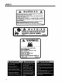
CALiFORNiA
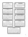
A WARNING
Proposition 65 Warning
Diesel engine exhaust and some
of its constituents are known to the
State of California to cause cancer,
birth defects and other reproductive
harm.
Californie
Proposition
Les 6chappements
de leurs compos6s
Califomie
The engine exhaust from this product
contains chemicals known to the State
of California to cause cancer, birth
defects or other reproductive harm.
65 Avertissemenl
A AVERTISSEMENT
des moteurs diesel et certains
sont reconnus
par l'Etat de
pour 6tre canc6rigbnes,
des d6fauts cong6nitaux
et d'autres
provoquer
dangers
en
matibre de reproduction.
California
Advertencia
de la Proposicion
L'6mission du moteur de ce mat6riel contient des produits chimiques que l'Etat de
Californie considbre 6tre canc6rigbnes,
provoquer des d6fauts cong6nitaux et
d'autres dangers en matibre de reproduction.
65
E1 estado de California hace saber que
los gases de escape de los motores diesel
y algunos de sus componentes producen
cfincer, defectos de nacimiento y otros
dafios en el proceso de reproducci6n
humana.
A ADVERTENCIA
E1estado de California hace saber que los
gases de escape de este producto contienen
productos qulmicos que producen cfincer,
defectos de nacimiento y otros dafios en
el proceso de reproducci6n humana.
CALIFORNIA
Proposition
65 Warning
Battery
posts,
terminals,
wiring
insulation,
and related accessories
contain lead and lead compounds,
chemicals
known to the State of
California to cause cancer and birth
defects or other reproductive
harm.
WASH HANDS AFTER HANDLING.
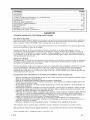
TABLE OF CONTENTS
SAFETY .........................................................................................................................................................
LABELS .......................................................................................................................................................
CONTROLS ...............................................................................................................................................
PRE-OPERATION CHECK LIST ....................................................................................................................
SET UP INSTRUCTIONS ..........................................................................................................................
OPERATION ..............................................................................................................................................
MAINTENANCE CHART ................................................................................................................................
MAINTENANCE RECORD ............................................................................................................................
MAINTENANCE ........................................................................................................................................
ADJUSTMENTS .......................................................................................................................................
BELT REPLACEMENT ...................................................................................................................................
SERVICE INFORMATION .............................................................................................................
BACK
PAGE
2-8
9-13
14-17
18
19-20
21-23
24
25
26-32
33-35
36
PAGE
WARRANTY
CRAFTSMAN
PROFESSIONAL
LIMITED WARRANTY
Two Years on Tractor
When operated and maintained according to all supplied instructions, if this tractor fails due to a defect in
material or workmanship within two years from the date of purchase, call 1-800-4-MY-HOME® to arrange for
free repair.
This warranty applies for only one year from the date of purchase if this tractor is ever used for commercial or
rental purposes.
During the first 30 days of purchase, there will be no charge to service the tractor in your home. For your convenience, in-home warranty service will still be available after the first 30 days of purchase, but a trip charge
will apply. This charge will be waived if you transport the tractor to an authorized Craftsman drop-off location.
For the nearest authorized location, call 1-800-MY-HOME®.
90-Days on Battery
For ninety (90) days from the date of purchase, if the battery included with this tractor is defective in material
or workmanship (our testing proves it will not hold a charge), it will be replaced free of charge.
During the first 30 days of purchase, there will be no charge to replace the defective battery in your home.
For your convenience, in-home warranty service will still be available after the first 30 days of purchase, but a
trip charge will apply. This charge will be waived if you transport the tractor to an authorized Craftsman dropofflocation. For the nearest authorized location, call 1-800-MY-HOME®.
This warranty
covers ONLY defects in material and workmanship.
Sears will NOT pay for:
• Expendable items that become worn during normal use, including but not limited to blades,
spark plugs, air cleaners, belts, and oil filters.
• Standard maintenance servicing, oil changes, or tune-ups.
• Tire replacement or repair caused by punctures from outside objects, such as nails, thorns,
stumps, or glass.
• Tire or wheel replacement or repair resulting from normal wear, accident, or improper operation
or maintenance.
• Repairs necessary because of operator abuse, including but not limited to damage caused by
towing objects beyond the capability of the tractor, impacting objects that bend the frame or
crankshaft, or over-speeding the engine.
• Repairs necessary because of operator negligence, including but not limited to, electrical and
mechanical damage caused by improper storage, failure to use the proper grade and amount
of engine oil, failure to keep the deck clear of flammable debris, or failure to maintain the
equipment according to the instructions contained in the operator's manual.
• Engine (fuel system) cleaning or repairs caused by fuel determined to be contaminated or
oxidized (stale). In general, fuel should be used within 30 days of its purchase date.
• Normal deterioration and wear of the exterior finishes, or product label replacement.
This warranty applies only while this product is within the United States.
This warranty gives you specific legal rights, and you may also have other rights, which vary, from state to
state.
Sears, Roebuck and Co., Hoffman Estates, IL 60179
11-2007
1
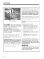
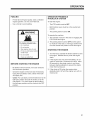
SAFETY
NOTICE
!!!
This symbol means:
ATTENTION!
BECOME ALERT!
Unauthorized modifications may present extreme
safety hazards to operators and bystanders and
could also result in product damage.
Your safety and the safety of others is involved.
Craftsman Professionalstrongly
warns against,
rejects and disclaims any modifications, add-on
accessories or product alterations that are not
designed, developed, tested and approved by
Craftsman Professional Engineering Department.
Any Craftsman Professional product that is altered,
modified or changed in any manner not specifically
authorized after original manufacture-including
the
addition of "aftermarket" accessories or component
parts not specifically
approved by Craftsman
Profesional-will result in the Craftsman Professional
Warranty being voided.
Any and all liability for personal injury and/or property
damage caused by any unauthorized modifications,
add-on accessories or products not approved
by Craftsman Professional will be considered
the responsibility of the individual(s) or company
designing and/or making such changes. Craftsman
Professional will vigorously pursue full indemnification
and costs from any party responsible for such
unauthorized post-manufacture modifications and/or
accessories should personal injury and/or property
damage result.
Signal
word definitions:
The signal words below are used to identify levels
of hazard seriousness. These words appear in
this manual and on the safety labels attached
to Craftsman Professional machines. For your
safety and the safety of others, read and follow the
information given with these signal words and/or
the symbol shown above.
DANGER indicates an imminently hazardous
situation which, if not avoided, WILL result in death
or serious injury.
WARNING
indicates a potentially
hazardous
situation which, if not avoided, COULD result in
death or serious injury.
A CAUTION
CAUTION indicates a potentially hazardous situation
which, if not avoided, MAY result in minor or moderate
injury. It may also be used to alert against unsafe
practices or property damage.
CAUTION
CAUTION used without the safety alert symbol
indicates a potentially hazardous situation which, if
not avoided, MAY result in property damage
MODEL NUMBER:
price lists.
This number appears on sales literature, technical manuals and
SERIAL NUMBER: This number appears only on your mower. It contains the model
number followed consecutively by the serial number. Use this number when ordering
parts or seeking warranty information.
Serial Number Tag is located under seat; on the far back wall of the frame; left of battery
from operators point of view.
2
SAFETY
PREPARING FOR SAFE OPERATION
Operator
preparation
and training
I G
Read the Operation & Safety
Manual
If an operator or mechanic
cannot read English, it is
the owner's responsibility
to explain this material to
them. If any portion of this
material is unclear, contact
your factory representative for
clarification.
Become familiar with the safe operation of the
equipment, operator controls and safety signs.
Know how to stop the engine and attachments
quickly in an emergency. Do not operate or allow
another person to operate this machine if there
are any questions about safety.
All operators and mechanics should be trained.
The owner is responsible for training the users.
Wear appropriate clothing, including long
trousers and safety goggles or safety glasses
with side shields when operating mower. Do not
operate barefoot or wearing open sandals. Long
hair, loose clothing or jewelry may get tangled in
moving parts.
All rotary lawnmowers
are potentially
dangerous. They can amputate hands and
feet and throw objects, Failure to follow
these safety and operating instructions
could result in serious injury or death.
Site preparation
and circumstances
Evaluate the terrain to determine what
accessories and attachments are needed to
properly and safely perform the job. Only use
accessories and attachments approved by the
manufacturer,
Wear hearing protection.
Clear the area to be mowed of objects such as
rocks, toys, wire or other debris that may be
picked up or thrown by the mower.
Never allow underage children, unskilled
or improperly trained people operate this
equipment. Local regulations can restrict the age
of the operator.
Be sure the area is clear of pets and people,
especially young children. Never assume they
will remain where you last saw them. Stop the
machine if any enter the area.
Data indicates that those operators age 60 years
and above are involved in a large percentage of
riding mower-related injuries. Those operators
should evaluate their ability to operate the riding
mower safely enough to protect themselves and
others from injury.
Mow only in daylight or in good artificial light.
Do not mow wet grass as tires may lose traction.
Do not carry passengers, especially small
children. They may fall off and be seriously
injured.
Keep warning labels and this operator's manual
legible and intact. Replacement labels and
manuals are available from the factory.
Do not operate machine while under the
influence of drugs or alcohol.
The owner/user can prevent and is responsible
for accidents or injuries occurring to themselves,
other people or property.
3
SAFETY
Machine
OPERATING
preparation
Check operator presence interlock system and
brake operation. Adjust or repair any problems
before using.
Do not tamper with or defeat safety devices.
Keep guards, shields and interlock safety devices
in place and in proper working condition. They
are for your protection.
Keep all fasteners such as nuts, bolts and pins
well secured.
Visually inspect blades, blade bolts and the cutter
assembly for wear or damage. Replace worn or
damaged blades and bolts to preserve balance.
Verify that machine and attachments,
in good operating condition.
if any, are
Do not engage blades until ready to mow.
SAFELY
in general
Use extra care when loading or unloading the
machine into a trailer or truck.
Slow down and use caution when making turns
and crossing roads and sidewalks. Stop blades if
not mowing.
Do not run the engine in an enclosed area where
dangerous carbon monoxide fumes can collect.
Do not place your foot on the ground while
operating the machine.
Before operating, lower the discharge chute,
install the mulcher or put the entire grass catcher
in place.
Keep clear of the discharge opening at all times.
Never direct the discharge toward a bystander.
Stop operation if someone approaches.
Keep washout ports and other mower housing
service openings closed when mowing.
Use care when pulling loads or using heavy
equipment.
Use only approved draw bar hitch points.
Limit loads to those you can safely control.
Do not turn sharply. Use care when reversing.
Use counter-weight(s) or wheel weights when
suggested in the operator's manual.
Never leave a machine unattended. Always turn
off blades, set parking brake, stop engine and
remove key before dismounting.
4
SAFETY
Starting
Start only according to instructions in this manual
or on the machine.
Before attempting to start the engine, make sure:
- the parking brake is on;
- the PTO is disengaged;
- the traction drive is in NEUTRAL.
When starting the engine, make sure hands and
feet are clear of the blades.
Do not start the machine while standing in front
of the discharge chute or with the chute directed
at someone.
Do not engage PTO at full throttle. Throttle to
idle or lowest possible engine speed.
Do not change engine governor settings or
over-speed the engine. Operating the engine
at excessive speed can increase the hazard of
personal injury.
interrupting
operation
Before leaving the operator's position:
- Park on level ground.
- Disengage the PTO.
- Set the parking brake.
- Shut off the engine and remove the key.
Disengage the PTO and wait until the blades quit
rotating:
- before raising cutterdeck;
- when not mowing;
- for transport;
- when crossing surfaces other than grass.
Stop the engine, disengage the PTO, set parking
brake and wait until the blades quit rotating and
lower cutting unit:
- before refueling;
- before removing grass catcher;
- before making height adjustment unless the
adjustment can be made from the operator's
position.
Stop the engine, disengage the PTO, set parking
brake and disconnect the spark plug wire(s) or
remove the key:
- before clearing blockages or unclogging chute;
- before checking, cleaning or working on the
machine;
- after striking a foreign object. Inspect the
machine for damage and make repairs before
restarting;
- if the machine begins to vibrate abnormally:
shut off machine immediately. Inspect and
make repairs as needed before restarting;
- except for repairs or adjustments as specifically
noted, such as for carburetor adjustment,
where the engine must be running. Keep
hands and feet clear of moving parts in these
circumstances.
Allow the blades to come to a complete stop
when stopping operation to clear blockages,
unclog, inspect the machine, do maintenance or
repair.
Reduce the throttle setting during engine shutdown and, if the engine is provided with a shutoff valve, turn the fuel off at the conclusion of
mowing.
5
SAFETY
MANEUVERING
SAFELY
in general
gradual. Do not make sudden changes in speed
or direction.
Slow down before turning•
Do not mow in reverse unless absolutely
necessary. Always look behind and down
for small children and pets before and during
backing.
Do not turn on slopes unless necessary, and then
turn slowly and downhill when possible.
Be aware when approaching blind corners,
shrubs, trees, tall grass or other objects that may
obscure vision.
Use lower speeds on a slope to avoid stopping or
shifting.
If tires lose traction, disengage the blades• If on
a slope, head downhill.
Use extra care with grass catchers or other
attachments. These can change the stability of
the machine.
Mowing
slopes
_lb WARNING
Slopes are a major factor in
loss-of-control and tip over
accidents that sometimes lead
to severe injury or death. All
slopes require extra caution.
Do not mow on slopes if uneasy or uncertain.
Ultimate responsibility for safe operation on
slopes rests with the operator.
Do not mow excessively steep slopes.
A slope is too steep if:
• The machine will not back up the slope.
• The machine must be crabbed (turned
partially sideways uphill) to drive across
the slope.
• The machine turns downhill going across slope.
• You are uneasy about being on the slope.
On zero turn machines, mow across slopes, not
up and down.
Avoid starting or stopping on a slope. If tires
lose traction, disengage the blades and proceed
slowly straight down the slope.
With a zero turn machine, if tires lose traction
going down a slope, steering control may be
regained by speeding up.
Mid-mount zero turns (belly mounted deck) have
much greater traction pointed up slope than
down slope. Be aware that traction may be lost
going down a slope. Do not operate a mid-mount
zero turn on slopes it cannot back up.
Keep all movement on the slopes slow and
6
Stay away from slopes if the ground is loose or if
caught in the rain during mowing.
Remove obstacles such as rocks, tree limbs etc.
Avoid driving over obstacles such as ruts, holes,
rocks and roots whenever possible. Be alert to
dips and rises. Uneven terrain can overturn a
mower or cause it to slide. Tall grasses can hide
obstacles.
Do not mow drop=offs, ditches or embankments.
The machine could suddenly turn over if a wheel
runs over the edge or an edge caves in•
Follow the manufacturer's recommendations
for wheel weights or counterweights to improve
stability.
Do not mow slopes when grass is wet• Reduced
traction could cause sliding.
SAFETY
MAINTENANCE
SAFETY
in general
Maintain machine according to manufacturer's
schedule and instructions for maximum safety
and best mowing results.
Park machine on level ground.
Never allow untrained personnel to service machine.
Adjust or repair only after the engine has been
stopped and the blades have quit rotating.
Inspect grass catcher components regularly. If
worn, damaged or deteriorated, they may expose
moving parts or allow objects to be thrown.
Replace parts if worn, damaged or faulty.
For best results, always replace with parts
recommended by the manufacturer.
Disconnect battery or remove spark plug wire(s)
before making any repairs. Disconnect the
negative terminal first and the positive last. Reconnect positive first and negative last.
Do not dismantle the machine without releasing
or restraining forces which may cause parts to
move suddenly.
Provide adequate support, e.g. jackstands for
lifted machine or parts if working beneath.
Do not put hands or feet near or under rotating
parts.
Clean up spilled oil or fuel thoroughly.
Replace faulty mufflers.
To reduce fire hazards, keep the engine, muffler,
battery compartment and fuel storage area free
of grass, leaves, debris buildup or grease.
Hydraulic fluid can penetrate skin, use paper
to check for leaks. Relieve hydraulic pressure
before disconnecting hoses. Make sure
connections are tight and hoses are in good
condition.
WARNING
Blades
Mower blades are sharp and
can cut. Use extra caution
when handling. Remove obstructions with care. Wrap the
blade(s) or wear gloves.
Be aware that rotating one
blade on multi-blade mowers can cause other
blades to rotate.
Only replace blades. Never straighten or weld
them.
Keep other persons away from blades.
WARNING
Fuel
Gasoline and diesel fuels are
flammable; gasoline vapors
are explosive. Use extra care
when handling.
Store only in containers specifically designed for fuel.
When refueling or checking fuel level:
-
Stop the engine
Do not smoke;
Refuel outdoors
Use a funnel;
Do not overfill;
If fuel is spilled,
engine until the
have cleared.
and allow to cool;
only;
do not attempt to start the
spill is cleaned up and vapors
Sparks from static electricity can start fires or cause
explosions. Flowing fuel can generate static
electricity. To prevent static electricity sparks:
Keep containers electrically grounded. Do not fill
containers in a vehicle or on a truck or trailer bed
with a plastic liner. Fill containers on the ground
away from the vehicle.
When practical, remove gas powered equipment from the truck or trailer and refuel it on the
ground. If equipment must be refueled on the
truck or trailer, refuel from a portable container
rather than a dispenser nozzle.
Keep the dispenser nozzle in contact with the rim
of the fuel tank or container opening until fueling
is complete. Do not use a nozzle lock-open
device.
Replace caps on fuel cans and tanks securely.
7
SAFETY
BATTERY
WARNING
Battery acid is caustic and fumes
are explosive and can cause
serious injury or death.
To reduce the risk of personal
injury when working near a battery:
When working with battery
-=
acid, use protective equipment
such as, but not limited to, goggles, face shield,
rubber gloves and apron.
,
2.
Position the machine with a good (charged) battery next to but not touching the machine with the
dead battery so jumper cables will reach.
3.
When making cable connections:
make sure the clamps do not touch anywhere
except to intended metal parts,
Never connect a positive ("+" or red) terminal
to a negative ("-" or black) terminal.
Make sure the cables won't get caught in any
parts after the engines are started.
Avoid leaning over a battery.
Do not expose a battery to open flames or
sparks.
Be sure batteries with filler caps are properly
filled with fluid.
Do not allow battery acid to contact eyes or skin.
Flush any contacted area with water immediately
and get medical help.
4.
Connect one end of the first jumper cable to the
positive terminal on one battery. Connect the
other end to the positive terminal on the other
battery.
5.
Connect one end of the other cable to the
negative terminal of the machine with a good
(charged) battery. Make the final connection on
the engine of the machine to be started, away
from the battery.
6.
Start the vehicle with the good battery, then the
machine with the discharged battery.
7.
Remove the cables in the exact reverse order of
installation. When removing each clamp, take
care it does not touch any other metal parts while
the other end remains attached.
Charge batteries in an open, well ventilated area,
away from sparks and flames. Unplug charger
before connecting or disconnecting from battery.
Stop the engine and allow to cool before storing.
Drain the fuel tank outdoors only.
Store fuel in an approved container in a cool, dry
place.
Keep the machine and fuel containers in a locked
storage place to prevent tampering and to keep
children from playing with them.
When the machine is to be parked, stored or left
unattended, lower the cutterdeck unless a positive mechanical lock is used.
Do not store the machine or fuel container near
heating appliances with an open flame such as a
water heater or an appliance with a pilot light.
Keep gasoline storage area free of grass, leaves
and excessive grease to reduce fire hazard.
Clean grass and debris from cutting units, drives,
mufflers and engine to help prevent fires.
8
Be sure the jumper cables are in good condition.
Turn off the ignition and all electrical accessories
on both machines.
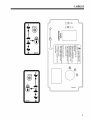
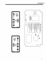
LABELS
©
T
rN
Z
6
!
R
tt3
f-I
I
0
•
I
I
:::r -0_
oo
P7
_- 5"8 _-= <>
2000700
O"__
C)
0 o
_
o-t1
-n
_
8
-
2000701
9
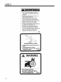
LABELS
1, L_r el manual del o_::_rador.No permitir
que personas no _pacitadas pa_ e_o usen
la m_quina,
2. Mantener los protectores en su lugar y sus
tomil{os debidamente _ados.
3. Antes de iimpiar, ajustar o reparar este
equipo, apagar todos los mandos, aplicar
e{ freno de es_cionamiento y apagar el motor.
4_ Mantener {as manos, los pies y la ropa
a{ejados de las piezas en movimiento,
5. No _nducir _mo pasajero ni liavar pasajeros
en m_quinas sin as_ento pan ello.
6 Mantener aias demos personas aiejadas
durante el funcionamiento de la m_quina.
7. Si no sabe I_r ing|_s, solici_de a otra _rsona
que le lea y expiique e! contenido de las
etiquetas y del manual de la m_quina.
340830
BLADE
iNSTALLATiON
=ROTATING PARTS.
=DO NOT OPERATE WiTH
COVER REMOVED.
2ooos77
10
LABELS
1
2720743
13
4126611
11
LABELS
,A
WARNING
,A
=REMOVE DEBRIS BUILDUP. DEBRIS UNDER BELT COVER OR
NEAR MUFFLER CAN CAUSE FIRES.
=BLADES CONTINUE TO ROTATE FOR A FEW SECONDS AFTER
BLADES ARE TURNED OFF.
=BLADES MUST BE AT LEAST 1/8" ABOVE BOTTOM OF HOUSING,
-ALL BLADES MUST BE iDENTICAL. CHECK BLADE BOLTS DAILY
FOR TIGHTNESS,
=iNSPECT FOR DAMAGE AFTER STRiKiNG A FOREIGN OBJECT,
MAKE REPAIRS BEFORE RESTARTING OPERATION.
=FIND AND REPAIR CAUSE OF ANY ABNORMAL ViBRATiON.
2000572
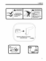
WARNING
SPARKS OR FLAME CAN START EXPLOSION,
DISCONNECT (=)NEGATIVE TERMINAL FIRST.
RECONNECT (=)NEGATIVE TERMINAL
LAST.
2000590
TO CHECK OR ADD FUEL:
=Do it outdoors.
-Stop engine. Allow to cool,
-Do not smoke.
-Clean up spilled fuel.
=Do not overfill.
-Fill to one inch below bottom of
filler neck.
12
2000570
LABELS
WARNING
DANGER
THROWN OBJECTS
= KEEP
ROTATING
= KEEP
HANDS
= STOP
ENGINE
STOP
GRASS
BLADES
AND
AND
BEFORE
FEET
AND
AWAY.
STRIKE
= STOP
OR
CLEAR
OF PEOPLE
PETS,
= REMOVE
LET BLADES
REMOVING
COLLECTOR
AREA
OBJECTS
AND
BLADES
BLADE
MAY
THROW.
TO CROSS
GRAVEL
AREAS
UNCLOGGING
•
DO NOT OPERATE
MULCHER
COLLECTOR
WITHOUT
OR ENTIRE
CHUTE,
GRASS
iN PLACE.
2000677
Operator's
Manual is located
14 |bs/in 2 (1 kglcm z)
•!2e80_
_i
13
CONTROLS
KEYSWITCH
(K) - The keyswitch has three
positions: OFF, RUN, and START. Insert the key
and turn it clockwise to move the switch from OFF to
RUN. Turn it further to START and hold to engage
the starter. Release the key and the switch will return
to RUN from START. Turn the key counterclockwise
to OFF to stop the engine.
THROTTLE
(T) - Move the throttle lever forward to
increase engine speed until the maximum governed
engine RPM is reached. Move the lever rearward to
decrease engine speed until the engine reaches its
idle speed,
CHOKE
(C)
For Kawasaki and Briggs and Stratton Engines, pull
the choke control out to set the choke ON. Push it in
to set the choke OFF.
POWER
TAKE OFF (PTO) SWITCH
(P)-
At operator's
right side
The operator must be in the seat when engaging the
PTO or the engine will kill. Pulling the PTO switch
out engages (turns on) the PTO and starts the blades
or other attachment. Pushing the PTO switch in
disengages (turns off) the PTO and stops the blades
or other attachment.
NOTE: The PTO switch does not control
attachments powered by a separate engine.
Disengage the PTO whenever you stop or leave
the operator's position
Shut off engine with the key and remove the
spark plug wires before making adjustments or
unplugging a clogged mower.
Do not engage the PTO until ready to start
mowing,
12 VOLT POWER
OUTLET
(X)
A 12 volt power outlet is provided to operate 12 volt
personal accessories.
14
Below seat
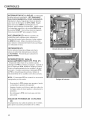
CONTROLS
FUEL SELECTOR
VALVE
(U)
The fuel tank selector valve is located behind the
seat,
The fuel tank selector valve has three positions:
Off: The tank selector is off when the lever points
down. The selector should be off whenever the
machine is transported or stands unused for any
length of time. Shutting off the fuel supply avoids the
possibility of flooding should any dirt get under the
carburetor float needle. Leaving the tank selector in
either tank position can allow severe flooding, which
may ruin the engine by diluting the oil.
Right Tank: Fuel flows from the right tank when the
selector is turned 1/4 turn toward the right.
Left Tank: Fuel flows from the left tank when the
selector is turned 1/4 turn toward the left.
15
CONTROLS
Reverse movement - To move the machine straight
back, pull both traction levers back equally from their
neutral position. Reverse speed increases as the
levers are moved back farther. Maximum reverse
speed is reached when the levers hit the rear of the
forward-reverse slot. When moving in reverse, pushing the levers forward slows the machine, and the
machine stops when the neutral position is reached.
NOTE: Reverse is spring loaded to return to neutral.
This spring resistance may be felt when moving the
traction levers into reverse. When the levers are
released in reverse, spring tension will slowly return
them to the neutral position.
Lift and traction
(operator's
levers
right side)
STEERING
- To steer, move one lever forward and
one back.
LIFT LEVER (F)
maximum height for
changing. To return
lever until it contacts
- Used to raise the cutterdeck to
transport, curb climbing or blade
to preset height of cut, lower lift
height of cut pin A.
TRACTION
LEVERS (L)- Each of the two
traction levers controls the drive wheel located on
the same side. They control the forward and reverse
movement of the machine, provide steering and also
provide dynamic braking.
The operator must be in the seat and the parking
brake must be OFF to engage the traction drive.
To engage traction drive, move the traction levers
toward the center of the machine until they are out of
neutral lock slot S.
Forward movement - To move the machine straight
ahead, push both traction levers forward equally from
their neutral position. Forward speed increases as
the levers are moved farther forward from the neutral
position. Maximum forward speed is reached when
the levers hit the front of the forward-reverse slot.
When traveling forward, pulling the traction levers
rearward slows the machine. The machine stops
when the neutral position is reached.
16
Turns during forward
movement:
Right turn - move the right traction lever back
toward neutral to slow the right drive wheel,
Left turn - move the left traction lever back toward neutral to slow the left drive wheel.
Turns during reverse movement:
Reverse right turn - move the right traction lever
forward toward neutral to slow the right drive
wheel.
Reverse left turn - move the left traction lever
forward toward neutral to slow the left drive
wheel.
Slow, sweeping turns are made with both traction
levers on the same side of neutral and slightly
apart. True zero radius turns about the center of the
machine are made by having one lever in reverse
while the other is in forward. By varying the relative
positions of the two levers, the rate of turn is varied to
suit the mowing situation.
Slow down before making sharp turns. The machine
is capable of turning very rapidly when the levers are
moved further apart from each other. Loss of control
and/or turf damage may result.
CONTROLS
PARKING
BRAKE (R) - Pull the parking brake
lever up and back to put the parking brake ON. Push
it forward and down to put the parking brake OFF.
The parking brake must be ON to start the engine.
It must also be ON to keep the engine running if the
operator leaves the seat. The parking brake must be
OFF to keep the engine running when a traction lever
is moved out of neutral lock.
Parking brake in ON position
(operator's left side)
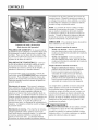
PUSHING
THE MACHINE
The machine may be pushed with the engine off, the
parking brake off, and the bypass valves open.
To open the bypass valves, move the parking brake
to the OFF position, then lift and pull bypass control
rod C through the large opening D, until the control
rod stop is past the opening. Drop rod C into the
small opening to lock in place. Repeat for the other
bypass control rod.
To close the bypass valves, lift bypass control rod C
allowing the control rod stop to retract through the
large opening D.
17
PRE-OPERATION
CHECK LiST
PRE-OPERATION CHECK LIST
(OPERATOR'S RESPONSIBILITY)
Review and follow all safety rules and safety
decal instructions.
Check that all safety decals are installed and in
good condition. Replace if damaged.
Check to make sure all shields and guards
are properly installed and in good condition.
Be sure that either the discharge shield or
complete vacuum attachment is installed.
Check that all hardware is properly installed.
and secured.
Check that equipment is properly and securely
attached to power unit.
Check to be sure engine is free of dirt and
debris. Pay particular attention to the cooling
fins, governor parts and muffler. Clean air
intake screen. Check air cleaner; service if
necessary.
18
Never allow riders.
Inspect area and remove stones, branches or
other hard objects that might be thrown,
causing injury or damage.
Clean area around oil fill dipstick. Remove
dipstick and check to be sure oil is in operating
range (between marks on dipstick). Add oil if
necessary but Do Not Overfill. Install dipstick
assembly firmly until cap bottoms out on tube.
Dipstick assembly must always be secured into
fill tube when engine is running.
Check all lubrication points and grease as
instructed in manual.
Check hydrostatic fluid level. Check to be sure
cooling fins on hydrostat are clean.
Perform a functional check of the safety
interlock system each time you operate the
unit.
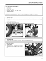
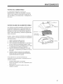
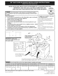
SET UP iNSTRUCTIONS
TOOLS REQUIRED FOR ASSEMBLY
Wrecking bar
Claw hammer
Sockets: 1/2", 15/16
Wrenches: 18mm, 1/2", 9/16", 3/4", 15/16"
Tire pressure gauge
NOTE: All references below to the "right" or "left" are with respect to an operator at the controls.
1. UNCRATE UNIT
a) Discard packing materials,
brackets.
Loosen the caster wheel axle bolts and bumper bolts to remove the shipping
Discard shipping brackets.
b) Re-install and tighten bumper bolts.
c)
Tighten caster wheel axle bolts against caster axle spanner bushings to 80 ft/Ibs.
2.
TIRE PRESSURE
a)
Set tire pressures to 14 Ibs/in 2 (1.0 kg/cm2). Tires are overinflated for shipping.
3, TRACTION
LEVERS
a)
Tighten bolt A.
b)
Sit on the machine. Levers C may be moved to
upper set of holes in bar B for a better operator
fit.
19
SETUP iNSTRUCTiONS
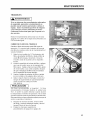
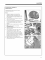
4. FINAL PREPARATIONS
Check the engine and hydraulic oil levels. Top offwith the correct oil if necessary.
for the engine. Use fresh, clean 20W50 motor oil for the hydraulic system.
Use 10W30 motor oil
Insure Battery cables are connected properly.
'--IAWARNING
Battery acid is caustic. Fumes are explosive and can cause serious injury or death.
Use insulated tools, wear protective glasses or goggles and protective clothing when working with batteries.
Read and obey the battery manufacturer's instructions.
Be certain the ignition switch is OFF and the key has been removed before servicing the battery.
a) Verify battery polarity before connecting or disconnecting the battery cables.
b) When installing the battery, always assemble the RED, positive ( + ) battery cable first and the
ground, BLACK, negative ( - ) cable last.
c)
Tighten cables securely to battery terminals and apply a light coat of silicone dielectric grease to
terminals and cable ends to prevent corrosion. Keep terminal covers in place.
Read Operation and Safety Manual before starting. Operator Manual is located under the seat. Tilt seat
forward to access manual.
--Ii,
OperatoCs Manual is located
If deck does not cut level, see deck leveling procedure in the Operator's Manual
Run engine at full RPM for 5 minutes before engaging blades to allow the engine to be fully lubricated
before load is applied.
Check the hydrostat neutral adjustment. Neutral is set at the factory but may require readjustment.
adjustments section in the operator's manual.
Do not use the machine without an approved grass collector, the grass discharge chute or mulching
plates correctly fitted.
20
See
OPERATION
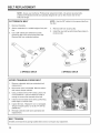
FUELING
Fill fuel tank with good quality, clean, unleaded
regular gasoline. Do not use hi-test fuel.
OPERATOR
iNTERLOCK
PRESENCE
SYSTEM
To start the engine:
Use a funnel to avoid spilling.
The PTO switch must be OFF.
Both traction levers must be in the neutral lock
position,
The parking brake must be ON.
WARNING
To operate the machine:
1. The operator must be in the seat or engaging the
PTO will kill the engine.
TO CHECK OR ADD FUEL:
- Do it outdoors
2. The parking brake must be OFF and the operator must be in the seat, or moving a traction lever
from the neutral lock position will kill the engine.
- Do not smoke
- Stop engine; allow to cool
- Fill to one inch below bottom
of filler neck
STARTING
,
- Do not overfill
- Clean up spilled fuel
BEFORE
STARTING
THE ENGINE
Be familiar with all controls, how each functions
and what each operates.
Check the engine oil level and add if necessary.
Using the fuel selector valve, select which tank
will supply fuel
THE ENGINE
Turn the key to operate the electric starter to start
the engine. Release the key when the engine
starts.
2. If the engine does not start immediately, do not
crank for more than 10 seconds at a time. Allow
60 seconds for the starter motor to cool down
between starting attempts to prevent the starter
motor from burning out.
3. If the choke is ON when the engine starts,
gradually back it off until the engine runs with no
choke at all.
Choke: For cold starts, set the throttle lever to the
half-open position and pull the choke out to the
ON position. For warm starts set the throttle to
the half-open position and the choke to the OFF
position.
21
OPERATION
OPERATING
NOTES
Practice at slow engine and travel speeds with the
PTO off until fully familiar with the controls.
For normal cutting the throttle should be set at the
full open position. By using the traction levers to
speed up or slow down the machine during use,
maximum control and cutting efficiency can be
maintained.
Using the machine at less than full throttle in
heavy conditions will cause the engine to labor
and result in excessive wear.
DRIVING
,
With the PTO disengaged, move the parking
brake to OFF.
2.
Move both traction levers out of neutral lock.
3.
Push both traction levers forward evenly to
drive forward in a straight line. Pull both traction
levers back evenly to drive backward in a straight
line.
4. Steering - Move one lever forward and one back.
Turns during forward
movement:
Right turn - move the right traction lever back
toward neutral to slow the right drive wheel,
Left turn - move the left traction lever back toward neutral to slow the left drive wheel,
Turns during
reverse
movement:
Reverse right turn - move the right traction lever
forward toward neutral to slow the right drive
wheel.
Reverse left turn - move the left traction lever
forward toward neutral to slow the left drive
wheel.
Use caution when making turns. Slow down before
making sharp turns to help maintain control and to
prevent torn turf from skidding or spinning tires. To
help prevent turf damage, keep both drive tires moving whenever a turn is made.
TIP: The best way to make a sharp "zero" turn is to
come to a stop, get the machine moving in reverse
with both drive wheels and then power the machine
around with the outside wheel. This technique keeps
the drive tires turning and results in less turf damage.
22
OPERATION
CUTTING
DANGER
1. Place the discharge chute in the down position or
correctly fit a grass collector or mulcher plate.
2.
Sit in the seat.
3.
Start the engine.
4. Turn the blades on by pulling up on the PTO
switch. Do not start the blades at full throttle.
Instead, use the slowest throttle setting that will allow the engine to pick up the blade load to reduce
the wear on the belts and electric clutch.
ROTATING
-
BLADES
KEEP HANDS AND FEET AWAY.
STOP ENGINE AND LET BLADES
BEFORE
TOR OR
REMOVING GRASS
UNCLOGGING.
STOP
COLLEC-
5. After the blades are rotating, set the throttle to
maximum. Use the traction levers to obtain the
WARNING
required cutting speed, to steer around obstacles
and to turn at the end of a cut.
THROWN
CUTTING
TiPS
When mowing large areas, start by turning to the
right so that clippings will be discharged away
from shrubs, fences, driveways, etc. After two or
three rounds, mow in the opposite direction, left
hand turns, until finished.
OBJECTS
-
KEEP AREA
-
AND PETS.
REMOVE OBJECTS
CLEAR
OF PEOPLE
-
STRIKE AND THROW.
STOP BLADES TO CROSS
BLADE
MAY
GRAVEL
AREAS
-
DO NOT OPERATE WITHOUT CHUTE,
MULCHER OR ENTIRE GRASS
CATCHER IN PLACE.
If grass is extremely tall, it should be mowed
twice, the first cut relatively high, the second cut to
the desired height.
Use the left side of the mower for trimming.
Choose cutting directions so that clippings are
thrown onto areas that already have been cut.
This method results in the most even distribution
of clippings and more uniform, better appearing
cuts.
Use a different mowing pattern each time where
possible. This helps prevent rutting and leads
to a more uniform cut by keeping the grass from
always laying the same way.
23
MAINTENANCE
CHART
X
X
X
X
X
X
X
*X
X
X
X
X
X
X
X
X
X
X
X
X
X
X
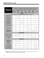
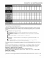
*Change oil after first 5 to 8 hours of use, then every 50 hours. Change oil every 25 hours when
operating the engine under heavy load or in high temperatures,
24
MAINTENANCE
RECORD
I
I
I
I
Repair
Protection
Agreements
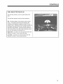
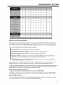
Congratulations on making a smart purchase. Your new Craftsman@ Professional product is designed
and manufactured for years of dependable operation. But like all products, it may require repair from
time to time. That's when having a Repair Protection Agreement can save you money and aggravation.
Here's what the Repair Protection
Agreement*
includes:
Expert Service by our 10,000 professional repair specialists
Unlimited
service and no charge for parts and labor on all covered repairs
_
Product replacement
up to $1500 if your covered product can't be fixed
_
Discount of 10% from regular price of service and related installed parts not covered by the
agreement; also, 10% off regular price of preventative maintenance check
_Fast
help by phone - we call it Rapid Resolution - phone support from a Sears representative.
Think of us as a "talking owner's manual."
Once you purchase the Repair Protection Agreement, a simple phone call is all that it takes for you to
schedule service. You can call anytime day or night, or schedule a service appointment online.
The Repair Protection Agreement is a risk-free purchase. If you cancel for any reason during the product
warranty period, we will provide a full refund. Or, a prorated refund anytime after the product warranty
period expires. Purchase your Repair Protection Agreement today!
Some limitations and exclusions apply.
For prices and additional information in the U.S.A. call 1=800=827-6655
*Coverage in Canada varies on some items. Full full details call Sears Canada 1=800=361=6665
Sears installation
Service
For Sears professional installation of home appliances, garage door openers, water heaters, and other
major home items, in the U.S.A. or Canada call 1-800-4-MY-HOME®.
25
MAINTENANCE
CHECK
DAILY
Operator
Presence interlock System =Start Operation
For the engine to crank, the parking brake must be on, the PTO (blades) off and traction levers in the neutral
lock position. Sit in the seat and check, one by one, if the engine will crank with the parking brake off, the
blades on, and either traction lever out of neutral lock.
Operator
Presence interlock System - Run Operation
The operator must be in the seat for the engine to run with the parking brake off, the traction levers moved out
of the neutral lock )osition, or the blades on. To check:
1.
2.
Start the engine and run at 1/2 throttle with the operator on the machine but raised off the seat.
One by one: move the parking brake to the OFF position, traction levers out of the neutral lock position
(check each independently), and turn the blades on. Each check should kill the engine after 1/2 second.
(A 1/2 second delay is built into the system to prevent engine cutout when traversing rough terrain.)
Repair machine before using if the Operator Presence Interlock System does not operate correctly in start or
run.
Hardware
Tighten any nuts and bolts found loose. Replace any broken or missing cotter pins. Repair any other problems before operating.
Tire pressure
Tires should be kept inflated to 14 Ibs/in2 (1.0 kg/cm2). Improper tire inflation can cause rapid tire wear and
poor traction. Uneven inflation can cause uneven cutting. Overinflation of caster tires can cause casters to
"wobble" on hard surfaces.
BATTERY
r L.,,.WARNING Battery acid is caustic and fumes
4.
are explosive and can cause serious injury or death.
Use insulated tools, wear protective glasses or
goggles and protective clothing when working with
batteries, Read and obey the battery manufacturer's
instructions.
NOTE: Sealed batteries cannot be checked or
topped off.
,
Be certain the ignition switch is OFF and the key has
been removed before servicing the battery.
1.
Verify battery polarity before connecting or disconnecting the battery cables.
2.
When installing the battery, always assemble
the RED, positive ( + ) battery cable first and the
BLACK ground, negative ( - ) cable last.
3.
When removing the battery, always remove the
BLACK ground, negative ( - ) cable first and the
red, positive ( + ) cable last.
26
Check the electrolyte level every 100 hours of
operation or yearly, whichever comes first. Top
off with distilled water if necessary.
,
Clean the cable ends and battery posts with steel
wool. Use a solution of baking soda and water
to clean the battery. Do not allow the solution to
enter into the battery cells.
Tighten cables securely to battery terminals and
apply a light coat of silicone dielectric grease to
terminals and cable ends to prevent corrosion.
Keep terminal covers in place.
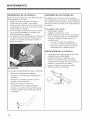
MAINTENANCE
4
$1
, r-i
II,
III
,j
L.............
2
, r .............
[-i
4
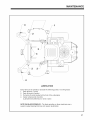
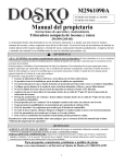
LUBRICATION
Every 50 hours of operation, lubricate the following points (1-3) with grease:
1. Deck lift lever (1 point)
2. Deck lift pivots (4 points)
3. Pull arms (2 points located at the front of the cutterdeck)
4. Caster wheel pivots (2 points)
(Lubricate every 500 hours or once a year)
NOTE ON BLADE SPINDLES =The blade spindles on these machines use a
superior sealed bearing that does not require relubrication.
27
MAINTENANCE
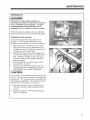
ENGINE
OIL
Perform engine maintenance with the engine off,
spark plug wires disconnected and PTO disengaged.
AFTER FIRST FIVE (5) HOURS
While the engine is warm:
1.
2.
3.
4.
Remove drain cap at location D and drain the
crankcase. Dispose of used oil in accordance
with local requirements.
Clean and replace the cap.
Change oil filter.
Fill the crankcase with fresh oil to the full mark.
Do not overfill. See engine manual for oil
specifications.
OIL CAPACITY
DAILY
1.
2.
Check oil level with the dipstick.
If oil is needed, add fresh oil of proper
viscosity and grade. See engine manual for oil
specifications. Do not overfill.
3. Replace dipstick before starting engine.
PERIODIC OIL CHANGES
1.
2.
See Page 22 maintenance chart for oil and filter
change intervals after the break-in period.
Follow instructions for first oil change, above.
Engine without oil filter holds approximately 1-7/8
quarts (60 ounces; 1.8 liters).
Engine equipped with oil filter holds approximately 2
quarts (64 ounces; 1.9 liters).
Use a high quality detergent oil classifed "For Service
SF, SG, SH, SJ" or higher.
Use recommended SAE viscosity grade oil per starting temperature according to Figure 1.
SAE Viscosity
Grades
Figure 1
F
SPARK
-20
0
20
32 40
60
80
100
PLUGS
Remove each plug and check condition.
-
Good operating conditions are indicated if the plug has a light coating of grey or tan deposit.
-
A white blistered coating indicates overheating. A black coating indicates an "over rich" fuel mixture.
Both may be caused by a clogged air cleaner or improper carburetor adjustment.
-
Do not sandblast, wire brush or otherwise attempt to repair a plug in poor condition.
obtained with a new plug.
-
Set plug gap as specified in engine manual..
28
Best results are
MAINTENANCE
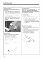
FUEL FILTER
An in-line fuel filter is located in the fuel supply line.
Inspect at every oil change to make sure it is clean
and unobstructed. Replace if dirty.
DUAL
ELEMENT
AIR CLEANER
KNOB
Engines equipped with dual element air cleaners
have a paper air cleaner element with an oiled, foam
precleaner element on the dirty side of the paper
element. Both should be inspected regularly and
maintained.
COVER
Clean and re-oil precleaner element every 25 hours
(more often under dusty conditions).
1.
Disassemble air cleaner cover.
2.
3.
Remove precleaner.
Wash precleaner in kerosene or liquid detergent
and water.
4.
Wrap precleaner in cloth and squeeze to remove
cleaner.
5.
Saturate precleaner in engine oil. Squeeze to
remove excess oil.
6.
Re-install precleaner. Reassemble air cleaner
components and screw assembly down tight.
BASE
Every 100 hours (more often under very dusty or dirty
conditions), check the paper cartridge.
-
Clean by tapping gently.
Do not wash the cartridge or use compressed air
which can cause damage.
Replace when cartridge is dirty, bent or
damaged.
29
MAINTENANCE
ENGINE
COOLING
Continued operation with a clogged cooling system
will cause severe overheating and can result in engine damage.
Daily:
Clean air intake screen V.
Every 100 hours: Clean cooling fins beneath
blower housing H with reference to information in
the engine manufacturer's manual.
SPECIFIC
TORQUES
BLADE
iWHEEL
ENGINE
PURGING
TRANSAXLES
Due to the effects air has on efficiency in hydrostatic
drive applications, it is critical that it be purged from
the system.
These
time a
cilitate
added
purge procedures should be implemented any
hydrostatic system has been opened to famaintenance or any additional fluid has been
to the system.
Purging may be required if the unit shows any of the
following symptoms:
- Noisy operation.
- Lack of power or drive after short term use.
- High operation temperature, excessive oil
expansion.
30
BOLTS
70 FT-LBS
HUB NUTS
CRANKSHAFT
150 FT-LBS
BOLT
50 FT-LBS
(203 Nm)
(68 Nrn)
TRANSAXLE
PULLEY
TRANSAXLE
DRAmN PLUG
15- 20 FT-LBS
TRANSAXLE
FILTER
130 - 150 in-robs(14.6 - 16.9 Nm)
1.
2.
3.
4.
5.
6.
NUT
(95 Nm)
28.3 - 41.6 FT-LBS
(20-
(38 - 56 Nrn)
27 Nrn)
Check the transaxle fluid, fill to proper level, if
required.
Raise the drive wheels off the ground. Support
unit with jackstands or other suitable means.
With the bypass valves open, and the engine
running, slowly move the control levers in both
forward and reverse directions 5 to 6 times. As
air is purged from the unit, the oil level will drop.
With the bypass valve closed, and the engine
running, slowly move the control levers in both
forward and reverse directions 5 to 6 times.
Stop engine. Check the transaxle fluid level, add
fluid as required.
It may be necessary to repeat steps 3-5 until all
the air is completely purged from the system.
When the transaxle moves forward and reverse
at normal speed, purging is complete.
MAINTENANCE
TRANSAXLES
Inattention to proper safety, operation, or
maintenance procedures could result in personal
injury, or damage to the equipment.
Jacobsen
recommends returning the machine to your
authorized CGC, Inc. dealer for service or repair.
Perform transaxle maintenance with the engine off,
spark plug wires disconnected and PTO disengaged.
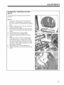
TRANSAXLE
FLUID CHANGE
Change the transaxle fluid every 200 hours of
operation. It is essential that the exterior of the
transaxle be free of debris, prior to fluid maintenance.
1.
2.
Remove the three 1/4" filter guard screws and
filter guard A. Remove the oil filter B from the
transaxle and discard. Dispose of used oil in accordance with local requirements.
Wipe the filter base surface off and apply a film
of new oil to the gasket of the new replacement
filter. Install the new filter by hand, turn 3/4 to
one full turn after the filter gasket contacts the
filter base surface.
3.
Re-install the filter guard and torque the three
screws to 65 in. Ibs. each.
4.
Remove cap C, fill the transaxles through the
expansion tank D with approximately 2 quarts of
SAE 20W-50 engine oil PER TRANSAXLE.
Do not overfill!
is "cold", it may
temperatures.
manufacturer's
needed for the
5.
6.
If you overfill the transaxle while the unit
overflow as it reaches normal operating
The oil level should not be above the
suggestions. This will allow the space
oil to expand as it warms up.
After starting engine, check the fluid level and
continue to add oil to overflow tank D to fill line
on tank.
Purge the transaxles, following the purging procedures on Page 29.
31
MAINTENANCE
BLADE
REMOVAL
Follow these instructions to prevent injury during
blade removal:
1. Loosen with a box wrench or a socket and long
breaker bar. To gain additional leverage, slip a
long pipe or thick-walled tube over breaker bar or
wrench.
2. Insert wood block A as shown, with grain
perpendicular to blade, to prevent blade from
turning when loosening.
3. Wear thickly padded gloves. Keep hands clear
of blade path. Blades may rotate when bolt
releases.
BLADE
Blade balance must be maintained at 5/8 oz-in (19.4
g-cm) or less. Failure to keep blades balanced
causes excess vibration, wear, and shortened life of
most components of the machine.
To balance a blade:
1.
2.
3.
Sharpen blade first.
Balance the blade at the center.
Attach a 1/8 oz (3.9 g) weight at a distance 5"
(127 mm) from center on the light end. This
should make the light end the heavy end:
If it does, the blade is balanced.
If does not, file or grind the heavy end until
the addition of the weight makes the light end
the heavy end.
BLADE
1.
2.
SHARPENING
BALANCE
3.
4.
INSTALLATION
Wear thickly padded gloves to prevent cuts from
the sharp blade.
Insert the blade bolt, in order, through the conical
washer (cup side toward the blade, as shown),
the blade, and the blade spacer.
Install assembly on the blade spindle.
Torque the blade bolt to 70 ft-lbs.
Blades may be sharpened by filing or grinding.
Inspect blades before sharpening.
Replace bent or cracked blades.
Replace blades when the lift portion has worn
thin.
Maintain cut angle at 30 °.
Do not overheat blades when sharpening.
Always use Craftsman Professeional blades.
Use of another manufacturer's blades may be
dangerous.
32
@
ADJUSTMENTS
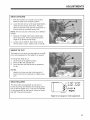
DECK
LEVELING
1.
Park the machine on a smooth, level surface.
Raise the deck to the transport position.
2.
Lower the deck onto a set of equal height blocks
under the rear corners of the deck. Place another set of blocks under the front of the deck so
that the deck top is pitched forward 1/8".
NOTE: The front and rear of the deck are at different
heights.
3.
Measure the height of the blade cutting edge
above the ground. Remove pin B and set the
height of cut lever E to that height
4.
Loosen nuts on bolts G. Move bolts in slot to
remove slack in chain. Tighten nuts on bolts G.
HEIGHT
OF CUT
The height of cut is set by moving height of cut pin B
to the hole designated for the height of cut desired.
To change the height of cut:
1.
2.
3.
Lift the deck to the highest position.
Move pin B to the selected hole.
Lower the deck until the lift lever is stopped by
the pin.
NOTES:
Height of cut may vary due to the amount of
tread on the tires, tire diameter or inflation pressure.
DECK
ROLLERS
The deck rollers are adjustable up and down to
provide improved deck flotation and scalping protection at various heights of cut. They are not intended
to ride continuously on the ground. Adjust no closer
than 3/8" (10mm) to the ground.
i
l
_:_
2-1/2"
-3-1/2"
3-1/2"
&
1-1/2" - 2-1/2"
Higher
Height of cut ranges for roller adjustment
33
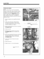
ADJUSTMENTS
PARKING
BRAKE
NOTE: There are 2 brakes, 1 on each transaxle.
The parking brake should keep the machine from
moving. To check the parking brake, park the machine on a level surface, open the bypass valves and
set the parking brake to ON. Attempt to move the
machine forward and backward by pushing it. If the
machine moves, adjust the parking brake linkage as
follows:
1.
Move the machine to a flat horizontal surface.
2.
Grip the flats on the brake rod A. Tighten nut
B on the brake rod until you run out of threads.
See Figure 1 for detailed view.
3.
Move the parking brake handle to the OFF
position.
4.
Loosen nut X.
5.
Hold brake arm in the OFF position as shown in
Figure 2.
6.
Adjust swivel U until swivel stud meets brake arm
hole in the OFF position.
7.
Insert cotter pin into swivel U.
8.
Tighten nut X.
9.
Repeat Steps 1-8 on the opposite side.
TIGHTEN UNTIL YOU
RUN OUT OF THREADS
FIGURE 1
FIGURE 2
34
ADJUSTMENTS
HYDROSTATIC
MENTS
TRANSA×LE
ADJUST=
A turnbuckle style hydrostat neutral adjustment is
provided,
Neutral:
1.
2.
3.
Support the machine with the rear wheels off
the ground. Use jackstands or equivalent sup=
port. Do not rely only on mechanical or hydraulic
jacks.
Move the traction levers out into the neutral lock
position and raise the seat.
Disconnect the seat switch wire and temporarily
connect the two terminals with jumper wire J as
shown.
4.
5.
6.
Start the engine and run at low speed.
Move parking brake to the OFF position.
Loosen jam nuts K at both ends of the control
rod L.
7.
Rotate the control rod until the corresponding
wheel stops turning. Lock the control rod jam
nuts. Run the engine up to high idle and stroke
the traction levers forward and back to check the
8.
9.
adjustment. Move traction levers back to neutral
and readjust if necessary.
Repeat steps 6 and 7 for the opposite side.
Remove the jumper wire and reconnect the seat
switch,
35
BELT REPLACEMENT
NOTE: Always use Craftsman Professional replacement belts, not general purpose belts.
Craftsman Professional belts are specially designed for use on this mower and will normally last longer.
CUTTERDECK
BELT
NOTE: Use the 3/8" ratchet in the square hole A on
the idler.
1.
Remove floorplate.
2.
Set the cutterdeck in a middle height-of-cut position.
.
Use a 3/8" ratchet and extension to back
tensioning idler off to remove belt from idler.
Remove belt from cutterdeck pulleys.
4.
Remove belt from clutch pulley.
5.
Install the new belt by performing these steps in
reverse order.
A
2 SPINDLE
HYDRO TRANSAXLE
DECK
3 SPINDLE
DRIVE BELT
1.
Remove cutterdeck belt (see cutterdeck belt
replacement).
2.
Disconnect wire I at clutch M. Remove bolts J
and remove torque restraint.
3.
Using a ratchet with a 9/16" socket, place over
nut at location P. Use the ratchet to rotate it
enough to remove the transaxle drive belt.
4.
Install a new transaxle drive belt by performing
these steps in reverse order.
5.
Inspect the fans. Replace if worn or damaged.
Torque transaxle pulley nut to 28.3-41.6 ft-lbs
(38-56 Nm).
6.
Reinstall cutterdeck belt (see cutterdeck belt
replacement).
BELT TENSION
All belts are tensioned by spring loaded idlers and do not require any adjustment.
36
DECK
Manual del operador
P R 0 F E
S
0 N A L
Podadora tipo tractor con radio de giro cero
Motor B&S de 26HP / descarga
Modelo 127.28875
lateral / 52 pulg. (132 cm) de ancho
Motor B&S de 22HP / descarga
Modelo 127.28876
lateral / 42 pulg. (132 cm) de ancho
Motor B&S de 22HP / descarga
Modelo 127.28877
lateral / 36 pulg. (132 cm) de ancho
PRECAUCION:
Antes de usar este
producto, lea el manual y siga todas las
instrucciones de seguridad y operacion
que contiene
Llame al siguiente numero para
obtener respuesta alas preguntas
que tenga sobre este producto:
1-800-659-5917
Linea de ayuda de Sears Craftsman
Lunes a sabado de 5 am a 5 pm
Sears, Roebuck and Co., Hoffman Estates, IL 60179 EE.UU.
Visite el sitio Web de Craftsman:
MAN 4163202
37
Rev. B 11-2008
www.sears.com/craftsman
MANUALDEPIEZAS4163201
WARNING
CALIFORNIA
Proposition
65 Warning
The engine exhaust from this product
contains chemicals known to the State of
California to cause cancer, birth defects
or other reproductive harm.
Diesel engine exhaust and some of its
constituents
are known to the State of
California to cause cancer, birth defects and
other reproductive harm.
Ca lifornie
Avertissement Proposition 65
A
AVERTISSEMENT
L'echappement du moteur de ce produit
contient des produits chimiques declares
par rEtat de la Californie responsables de
cancer, malformations congenitales ou
autres anomalies de la reproduction.
L'echappement
d'un moteur diesel et
certains de ses constituants sont declares
par I'Etat de la Californie responsables de
cancer, malformations congenitales et autres
anomalies de la reproduction,
California
Advertencia
ADVERTENClA
sobre la Proposicion 65
El escape del humo emanado pot este
producto es considerado en el estado
de California
como una mezcla de
sustancias qulmicas que causan cancer,
defectos congenitos y dahos en el sistema
reproductivo.de reproducci0n humana.
Los gases de escape de los motores diesel
y sus constituyentes son considerados en el
estado de California como sustancias que
causan cancer, defectos congenitos y danos
en el sistema reproductivo,
CALIFORNIA
Proposition
CALIFORNIE
65 Warning
Avertissement
Battery posts, terminals, wiring insulation, and
related accessories contain lead and lead
compounds, chemicals known to the State of
California to cause cancer and birth defects
or other reproductive harm. WASH HANDS
AFTER HANDLING.
Proposition
65
Les bornes de batterie, raccords, gaines de
ills et accessoires associ6s contiennent du
plomb et des composes de plomb declares
par rEtat de la Californie responsables de
cancer, malformations congenitales ou autres
anomalies de la reproduction.
SE LAVER
LES MAINS APRES MANIPULATION.
CALIFORNIA
Advertencia
sobre la Proposicion
65
Los bornes, terminales, material de aislamiento de los
cables de las baterias y los accesorios relacionados
contienen plomo y compuestos del plomo, que son
sustancias
quimicas que el estado de California
considera que causan cancer, defectos congenitos u
otros dahos en el sistema reproductivo. LAVESE LAS
MANOS DESPUES DE MANE JAR EL PRODUCTO.
38
CONTENIDO
PAGINA
SEGURIDAD .............................................................................................................................................
40-46
ETIQUETAS ..............................................................................................................................................
47-51
CONTROLES ............................................................................................................................................
52-55
LISTA DE VERIFICACION ANTES DE LA OPERACION ...............................................................................
56
ESTABLEZCA INSTRUCTIONES .............................................................................................................
57-58
OPERACION .............................................................................................................................................
59-61
TABLA DE MANTENIMIENTO .......................................................................................................................
62
REGISTRO DE MANTENIMIENTO ...............................................................................................................
63
MANTE NIMIE NTO ....................................................................................................................................
64-70
AJUSTES .................................................................................................................................................
71-73
REEMPLAZO DE LA CORREA ......................................................................................................................
74
INFORMACION SOBRE EL SERVICIO .........................................................................
PAGINA POSTERIOR
GARANTiA
GARANTiA
LIMITADA DE CRAFTSMAN
PROFESSIONAL
Dos anos en el tractor
Si este tractor falla debido a defectos en el material y la mano de obra en un lapso de dos ahos a partir de la
fecha de la compra, y se ha usadoy
mantenido de acuerdo con las instrucciones
del manual del operador,
Ilame al telefono 1-800-4-MY-HOME
para coordinar que se le repare sin costo.
Si este tractor alguna vez se usa con propositos comerciales o de arrendamientos,
pot un aho a partir de la fecha de la compra.
esta garantia aplica solo
Durante los primeros 30 dias de la compra el servicio al producto en su hogar ser_i gratuito. Para su
conveniencia, aun podr_i recibir el servicio de la garantia en su hogar despues de los primeros 30 dias de
la compra, pero se le aplicar_fi un cargo pot el viaje. Si Ileva el producto a un centro de entrega autorizado
por Craftsman, no se le har_i este cargo. Llame al 1-800-MY-HOME
para saber la ubicacion del centro de
entrega autorizado m_is cercano.
90 Dias erl la Bateria
Si la bateria que se incluye con este tractor presenta defectos en el material o la mano de obra (se determina
mediante nuestras pruebas que no almacena carga) en el periodo de noventa (90) dias a partir de la fecha
de compra, se reemplazar_i sm costo alguno.
Durante los primeros 30 dias de la compra no se le har_i cargo alguno por reemplazar la bateria en su hogar.
Para su conveniencia, aun podr_i recibir el servicio de la garantia en su hogar despues de los primeros
30 dfas de la compra, pero se le aplicar_i un cargo pot el viaje. Si Ileva la tractor a un centro de entrega
autorizado por Craftsman, no se le har_i este cargo. Llame al 1-800-MY-HOME
para saber la ubicacion del
centro autorizado m_is cercano.
Esta garantia
cubre
solo
defectos
en la materia
y la habilidad.
Sears
no pagar,i
por:
• Arficulos fungibles que se desgasten durante el uso normal, inclusive pero sin limitarse a cuchillas, bujias,
filtros de aire, correas y filtros de aceite.
• Servicio de mantenimiento est&ndar, cambios de aceite o afinaciones.
• Reemplazo o reparaci6n de los neum_ticos requerida por perforaciones con objetos extrados tales como
clavos, espinas, tocones o vidrio.
• El reemplazo de la Ilanta o la rueda o repara reulting de uso normal, del accidente, o de la operaci6n o la
conservacion impropias.
• Reparaciones necesarias causadas pot abuso del operador, inclusive pero sin limitarse a da_os causado
por remolcar objetos que excedan la capacidad del tractor, golpear objetos que doblen la armadura o el
cigQehal u operacion del motor a una velocidad excesiva.
• Reparaciones necesarias debido a negligencia del operador, inclusive pero sin limitarse a da_os elOctricos
ydmec_inicos causados pot almacenamiento inadecuado, uso de una cantidad y calidad inadecuadas
el aceite para motor, acumulaci6n de residuos inflamables en la coraza o negligencia para mantener el
equipo de acuerdo con las instrucciones del manual del operador.
• Limpieza o reparaci6n del motor (sistema de combustible) requerida debido a la contaminaci6n u
oxidacion (rancidez) del combustible. En general, el combustible se debe usar en un lapso de 30 dias a
partir de la fecha de su compra.
• Deterioro y desgaste norma/del acabado exterior, o reemplazo de las etiquetas del producto.
Toda cobertura bajo la garantia aplica solamente cuando el producto se encuentra en Estados Unidos.
Esta garanfia le otorga derechos legales especificos, y usted puede tener otros que vadan entreestados.
Sears, Roebuck and Co., Hoffman Estates, IL 60179 EE.UU.
11-2008
39
SEGURIDAD
iAVISO!
Este simbolo significa:
Las modificaciones no autorizadas pueden causar
riesgos extremos a la seguridad de operadores y
espectadores, y tambien podrian causar dahos al
producto.
Craftsman Professional se opone, rechaza y se libera
de toda responsabilidad por cualquier modificaci6n,
adicion de accesorios o alteraciones del producto
que no esten disehados, desarrollados, probados
y aprobados por el Departamento de Ingenieria
de Crafstman Professional.
Cualquier alteracion,
modificaci6n o cambio realizado a un producto
de Craftsman Professional de una manera que
no sea especificamente
autorizada despuOs de
la manufactura
original,inclusive
la adicion de
accesorios o piezas de posventa especiflcamente
aprobadas por Craftsman Profesional, dar_i como
resultado la anulacion de la garantia de Craftsman
Professional.
Cualquiera y toda responsabilidad
por lesiones
personales y/o dahos materiales causados por
cualquier modificaciOn, accesorio o producto adadido
que no sea aprobado por Craftsman Professional
se considerar_i responsabilidad de la persona o
personas o compahia que disehe y/o implemente
tales cambios. Craftsman Professional reclamar_i
vigorosamente la indemnificaciOn y los costos totales
resultantes a cualquier parte responsable de tales
modificaciones y/o accesorios postmanufactura no
autorizados si dan como resultado una lesion personal
o dahos materiales.
iATENCION!
iMANTENGASE
ALERTA!
Su seguridad y la seguridad de otras personas
est,1 involucrada.
Definici6n
de las palabras
de aviso:
Las siguientes palabras de aviso se usan para
identiflcar los niveles de riesgo. Estas palabras
aparecen en este manual y en las etiquetas de
seguridad adheridas alas m_fiquinas Craftsman
Professional. Por su seguridad y la seguridad de
otras personas, lea y observe la informacion que
se proporciona con estas palabras de aviso y/o el
simbolo que aparece arriba.
IAPEUGRO
l
PELIGRO indica una situacion de inminente peligro
que, si no se evita, DARA como resultado la muerte
o lesiones graves.
I ADVERTENCIA
i
ADVERTENCIA indica una situacion de peligro
potencial que, si no se evita, PUEDE DAR como
resultado la muerte o lesiones graves.
IA PRECAUCION
]
PRECAUCION indica una situacion de peligro
potencial que, si no se evita, PUDIESE BAR como
resultado lesiones graves o moderadas. Tambien se
puede usar para alertar contra pr_icticas inseguras
o dahos materiales.
[ PRECAUCION
i
PRECAUCION sin el simbolo de alerta de seguridad
indica una situacion potencialmente peligrosa que,
si no se evita, PUDIESE DARcomo resultado dahos
materiales
NUMERO DE MODELO:
de precios.
Este numero aparece en los folletos de venta, manuales tecnicos y listas
NOMERO DE SERIE: Este numero aparece s01o en su podadora. En ella aparece el numero de
modelo seguido consecutivamente por el numero de serie. Use este numero al pedir piezas o informacion sobre la garantia.
Numero de serie ubicado bajo el asiento, en la medida de nuevo muro, a la izquierda de la bateria
de los operadores oint de vista.
4O
SEGURIDAD
PREPARANDO
Preparaci6n
PARA LA OPERACION SEGURA
y capacitaci6n
ADVERTENCIA
del operador
Lea el iVianual de operaci6n y
seguridad
Si un operador o
mecanico no entiende
estas instrucciones, es
responsabilidad del
propietario explicarle
este material. Si
cualquier porci6n de este material no es clara,
comunfquese con su representante de fabrica
para que se la explique.
Familiarfcese con la operation segura del
equipo, los controles del operador y los avisos
de seguridad. Aprenda a apagar rapidamente el
motor y los accesorios en caso de emergencia.
No opere, ni permita que otra persona opere esta
maquina, si tiene preguntas sobre la seguridad.
Todos los operadores y mecanicos deben recibir
capacitacion. El propietario es responsable de la
capacitacion de los usuarios.
Cuando opere la podadora use un atuendo
apropiado, inclusive pantalones largos y galas o
anteojos de seguridad con protectores [aterales.
No opere la unidad mientras esta descalzo o usa
sandalias. El pelo largo, la ropa holgada o las
joyas o bisuteria pueden atorarse en las piezas
moviles.
Use protectores de la audicion.
Nunca permita que los nir_os o personas no
calificadas o inadecuadamente capacitadas
operen este equipo. Los reglamentos locales
pueden restringir la edad del operador.
Los datos indican que los operadores de 60
ahos de edad y mas estan involucrados en
un mayor porcentaje de lesiones relacionadas
con la operaci0n del tractor podadora. Estos
operadores deben evaluar su capacidad para
operar la unidad de manera segura a fin de
protegerse ellos mismos y a otros contra
lesiones.
Todas
las podadoras
rotatorias
son
potencialmente
peligrosas.
Pueden amputar
manosy piesy lanzar objetos. El incumplimiento
de estas instrucciones de seguridad y operacion
puede dar como resultado lesiones graves o
la muerte.
El propietario/usuario puede prevenir sufrir, o que
otras personas sultan, accidentes o lesiones y
dar_os a la propiedad, y es responsable de ellos
si suceden.
Preparacion
y circunstancias
del sitio
EvalOe el terreno a fin de determinar los
accesorios y dispositivos necesarios para
realizar el trabajo de manera apropiada y
segura. Use solamente accesorios y dispositivos
aprobados pot el fabdcante.
Quite del area que va a podar objetos tales
como rocas, juguetes, alambre y otros residuos
que pudiesen set captados y lanzados pot la
podadora.
Aseg0rese de que el _irea este libre de mascotas
y personas, especialmente de nirlos pequer_os.
Nunca suponga que se quedar_in en el lugar
donde los vio pot ultima vez. Detenga la
m_iquina si entran en el _irea de trabajo.
Pode solamente durante el dia o con una buena
iluminaci6n artificial.
No pode el cesped cuando este mojado porque
las ruedas pueden perder traccion.
No Ileve pasajeros, especialmente nirlos
pequer_os, ya que se pueden caer y sufrir
lesiones graves.
Mantenga las etiquetas de advertencia y este
manual del operador de manera legible e intacta.
La fabrica tiene disponibles etiquetas y manuales
de repuesto.
No opere la maquina mientras se encuentre bajo
la infiuencia del alcohol o las drogas.
41
SEGURIDAD
Preparacion
de la maquina
Revise el sistema de enclavamiento de presencia
del operador y la operacion de los frenos. Ajuste
o repare cualquier problema antes de usar la
unidad.
No altere ni anule ningun dispositivo de
seguridad. Mantenga los protectores, escudos
y dispositivos de enclavamiento de seguridad
en su lugar yen buenas condiciones de trabajo.
Estos articulos est_in disehados para su
proteccion.
OPERACION
En
SEGURA
general
Use extremo cuidado al cargar o descargar la
m_iquina de un trailer o camion.
Reduzca la velocidad y tenga cuidado al virar o
cruzar carreteras o aceras. Si no est,1 podando,
detenga las cuchillas.
No opere el motor en un _irea cerrada en la
que se puedan acumular vapores peligrosos de
monoxido de carbono.
Mantenga todos los sujetadores como tuercas,
tornillos y pernos bien apretados.
No coloque el pie en el piso mientras opera la
m_iquina.
Inspeccione visualmente las cuchillas, los
tornillos de las cuchillas y el conjunto de la
cortadora para asegurarse de que no esten
dahados ni desgastados. Cambie las cuchillas
y los tornillos desgastados o dahados para
conservar el equilibrio.
Antes de operar la unidad, baje el canal de
descarga, instale el triturador de mantillo o
coloque todo el captador de cesped en su lugar.
Verifique que la m_quina y sus accesorios, si los
tiene, esten en buenas condiciones.
No embrague las cuchillas sino hasta que este
listo para podar.
En todo momento mantengase alejado de la
abertura de descarga. Nunca dirija la descarga
hacia un observador. Interrumpa la operacion si
alguien se acerca.
Mantenga cerrados los puertos de enjuague y
otras aberturas de servicio ubicadas en la coraza
de la podadora cuando este podando.
Tenga cuidado la jalar cargas o usar equipo
pesado.
Use solo los puntos de enganche aprobados
de la barra de traccion
Limite las cargas a aquellas que puede
controlar con seguridad.
No vire en _ingulos cerrados. Tenga cuidado al
marchar en reversa.
Use uno o m_is contrapesos o pesos en las
ruedas cuando asi Io recomiende el manual del
operador.
Nunca deje una m_iquina desatendida. Siempre
desembrague las cuchillas, ponga el ffeno de
mano, apague el motor y saque la Ilave antes de
desmontar la unidad.
42
SEGURIDAD
Arranque
Arranque solamente de acuerdo con las
instrucciones de este manual o de la m_iquina.
Antes de intentar arrancar el motor, asegurese
que:
- el freno de mano este embragado;
la toma de potencia (PTO) este
desembragada;
- el mecanismo de traccion este en posicion
NEUTRA.
AI arrancar el motor, asegurese de tenet las
manos y los pies lejos de las cuchillas.
No arranque la m_iquina cuando se encuentre
frente al canal de descarga o cuando este este
orientado hacia alguna persona.
No acelere la PTO al m_iximo. Acelere hasta
marcha al vacio o a la velocidad m_is baja
posible del motor.
No altere los ajustes del regulador del motor ni
acelere excesivamente el motor. La operacion
del motor a una velocidad excesiva puede
aumentar el riesgo de lesiones personales.
Interrupci6n
de la operaci6n
Antes de abandonar la posicion del operador:
- Estaci6nese sobre superficies niveladas.
Desembrague la PTO.
Ponga el freno de mano.
Apague el motor y saque la Ilave.
Desembrague la PTO y espere hasta que las
cuchillas dejen de girar:
antes de elevar la plataforma de la cortadora;
cuando no este podando;
para transportar la unidad;
- al cruzar superficies que no est6n cubiertas de
cesped.
Detenga el motor, desembrague la PTO,
ponga el freno de mano y espere hasta que las
cuchillas dejen de girar para bajar la unidad de
core:
antes
antes
antes
hacer
de reabastecer de combustible;
de quitar el captador de cesped;
de ajustar la altura, a menos que pueda
el ajuste desde la posicion del operador.
Detenga el motor, desembrague la PTO, ponga
el freno de mano y desconecte el cable o cables
de las bujfas o quite la Ilave:
antes de eliminar obstrucciones o desatascar
el canal de descarga;
antes de revisar, limpiar o trabajar en la
m_iquina;
despues de golpear cualquier objeto extraho.
Antes de volver a arrancar la m_iquina,
inspecci6nela para verificar que no tenga
dahos y hacer las reparaciones en caso de que
los tenga.
SI la m_iquina comienza a vibrar de manera
anormal: ap_iguela inmediatamente. Antes de
volver a arrancarla inspeccionela y haga las
reparaciones necesarias;
excepto por las reparaciones o ajustes
especialmente indicados, como el ajuste
del carburador cuando el motor debe estar
funcionando. En estos casos mantenga las
manos y los pies alejados de las piezas en
movimiento.
Cuando apague la unidad para eliminar
obstrucciones, desatascar, inspeccionar, dar
mantenimiento o reparar la m_iquina, permita que
las cuchillas se detengan completamente.
Reduzca la aceleracion durante el apagado del
motor y, si este se suministra con una wilvula de
cierre, cierre la wilvula del combustible cuando
termine de podar.
43
SEGURIDAD
IVIAN[OBRAR
SiN
PELIGRO
En genera[
Reduzca la velocidad antes de virar.
No pode en reversa a menos que sea
absolutamente necesario. Siempre mire detr_is
de usted y hacia abajo para asegurarse de que
no haya nihos ni mascotas a su paso mientras
marcha en reversa.
Tenga cuidado al acercarse a esquinas degas,
matorrales, _irboles, cesped alto o a otros objetos
que puedan obstruir su vista.
Si las ruedas pierden traccion, desembrague las
cuchillas. Si se encuentra en una pendiente,
dirijase hacia abajo.
Podada
de pendient_
Las
pendientes
son
factor importante en los
accidentes de perdida de
control y volcaduras que
veces ocasionan lesiones
ADVERTENCIA
un
Las m_iquinas de montaje central y radio de giro
cero tienen una traccion mucho mayor pendiente
arriba que pendiente abajo. Note que puede
perder traccion cuando se dirige pendiente
abajo. No opere m_iquinas de montaje central y
radio de giro cero si no puede retroceder.
Mientras se encuentre en una pendiente
muevase lenta y gradualmente. No cambie
repentinamente la velocidad ni la direccion.
No vire en las pendientes a menos que sea
necesario, y cuando Io haga vire lentamente y
hacia abajo siempre que sea posible.
Mantengase alejado de pendientes que tengan la
superficie suelta o si Ilueve mientras poda.
j
a
graves o la muerte. Todas
las pendientes requieren precauciones adicionales.
No pode pendientes si se siente incomodo o no
est_ seguro. La responsabilidad definitiva de
la operacion segura en pendientes recae en el
operador.
No pode en pendientes excesivamente
empinadas.
Una pendiente es excesivamente empinada
cuando:
• La m_quina no marcha en reversa hacia arriba.
• Usted debe virar parcialmente de lado,
pendiente arriba, para conducir pot la misma.
• La m_quina se voltea hacia abajo al atravesar
la pendiente.
• No se siente seguro en la pendiente.
Si opera una m_iquina con radio de giro cero,
pode transversalmente a la pendiente, no
paralelamente.
Evite arrancar o detenerse en una pendiente.
Si las ruedas pierden traccion, desembrague
las cuchillas y avance con lentitud directamente
hacia abajo.
44
En las m_iquinas de radio de giro cero, cuando
las ruedas pierden traccion y va pendiente
abajo, puede recuperar el control de la direccion
acelerando.
Cuando se encuentre en una pendiente use las
velocidades m_is bajas para evitar detenerse o
cambiar de velocidad.
Tenga especial cuidado con los captadores de
cesped o con otros accesorios, ya que pueden
cambiar la estabilidad de la m_iquina.
Quite obst_iculos tales como rocas, ramas de
_irboles, etc.
Evite pasar sobre obst_iculos tales como baches,
hoyos y raices siempre que sea posible. Este
alerta alas depresiones y elevaciones del
terreno. Un terreno irregular puede causar el
volcamiento o el deslizamiento de una podadora.
El cesped alto puede ocultar obst_iculos.
No pode pendientes abruptas, zanjas ni
terraplenes. La podadora se puede volcar
repentinamente si una de sus ruedas sobrepasa
el borde o uno de los bordes se desploma.
Siga las recomendaciones del fabricante
referentes a pesos o contrapesos de las ruedas
para mejorar la estabilidad.
No pode las pendientes cuando el cesped este
humedo, ya que la traccion reducida puede
causar resbalamientos.
SEGURIDAD
SEGURIDAD
DE MANTENIMIENTO
En general
Proporcione mantenimiento a la m_iquina de
acuerdo con el programa y las instrucciones del
fabricante para obtener la mayor seguridad y los
mejores resultados.
Estaci6nese sobre superficies niveladas.
Nunca permita que personal no capacitado
proporcione servicio a la m_iquina.
Ajuste o repare la unidad solo hasta que el motor
se haya detenido y las cuchillas dejen de girar.
Inspeccione regularmente los componentes del
captador de cesped. Si est_in desgastados,
daflados o deteriorados, pueden exponer las
partes en movimiento o permitir el lanzamiento
de objetos.
Reemplace las piezas desgastadas, dafladas o
defectuosas. Siempre use piezas recomendadas
pot el fabricante para obtener los mejores
resultados.
Desconecte la bateria o quite el cable o
cables de las bujias antes de hacer cualquier
reparacion.
Desconecte primero el terminal
negativo y luego el positivo. Conecte pdmero el
terminal positivo y luego el negativo.
No desmonte la m_iquina sin pdmero liberar
o restringir las fuerzas que pueden causar el
movimiento repentino de las piezas.
Siva a trabajar debajo de la m_iquina use
soportes adecuados, como soportes para gatos,
para apoyar la m_iquina o sus partes elevadas.
No coloque las manos ni los pies cerca o debajo
de las partes en movimiento.
Limpie minuciosamente
combustible.
los derrames de aceite o
Reemplace los silenciadores defectuosos.
Para reducir el riesgo de incendio, mantenga
el motor, el silenciador, el compartimiento
de la bateria y el _irea de almacenamiento
de combustible sin cesped, hojas, residuos
acumulados y grasa.
El fluido hidr_ulico puede penetrar la piel,
use papel para detectar fugas. Libere la
presion hidr_iulica antes de desconectar las
mangueras. Asegurese de que las conexiones
esten apretadas y las mangueras en buenas
condiciones.
_
Cuchillas
Las cuchillas de la
podadora est_n filosas y
pueden cortar. Tenga cuidado
especial al manejarlas.
ADVERTENCIA
Elimine las obstrucciones con cuidado.
la(s) cuchilla(s) o use guantes.
Envuelva
Tenga en cuenta queen el caso de podadoras de
multiples cuchillas, el movimiento de una cuchilla
puede causar el movimiento de las otras.
Solamente reemplace las cuchillas, nunca las
enderece ni las repare con soldadura.
No permita que otras
personas se acerquen
alas cuchillas.
A
ADVERTENCIA
Combustible
La gasolina y el diesel son
inflamables; los vapores de
gasolina son explosivos.
Tenga cuidado especial al
manejarlos.
AlmacOnelos s61o en recipientes especificamente
diseflados para ellos.
AI reabastecer de combustible o revisar el nivel:
Pare el motor y permita que se enfrie;
No fume;
Reabastezca el combustible solo en exteriores;
Use un embudo;
No Ilene excesivamente el deposito.
Si el combustible se derrama, no intente
arrancar el motor sino hasta que limpie el
derrame y desaparezcan los vapores.
Las chispas de la electricidad constante pueden
comenzar explosiones de fuegos o causa. El
combustible corriente puede engendrar electricidad
constante. Para prevenir chispas constantes de
electricty:
Mantenga contenedores molieron electricamente.
No Ilene recipientes que se encuentren en
un vehiculo ni en un camion o trailer cuya
plataforma tenga un forro pl_istico. Llene los
recipientes en el suelo, lejos del vehiculo.
Cuando sea pr_ictico, baje todo equipo a gas del
camion o trailer y reabastezcalo de combustible
en el suelo. Si debe reabastecer el equipo
mientras se encuentra en el camion o trailer,
h_figalo usando un recipiente port_itil, no la
boquilla surtidora.
Mantenga la boquilla surtidora en contacto
con el borde del tanque del combustible o con
la abertura del recipiente hasta completar el
abastecimiento. No use un dispositivo para
mantener abierta la boquilla.
Vuelva a tapar seguramente las latas y los
tanques de combustible.
45
SEGURIDAD
BATER|A
_
El _dcidode la bateria es c_iustico
Quite el cesped y los residuos de las unidades
de corte, accionadores, silenciadores y el motor
para evitar incendios.
ADVERTENCIA
y los vapores son explosivos y
pueden causar lesiones graves o
la muerte.
1.
Asegurese de que los cables de arranque
auxiliar esten en buenas condiciones. Apague
la ignicion y todos los accesorios electricos en
ambas m_iquinas.
AI trabajar con el _icido de la
bateria, use equipo protector que incluya, pero
no se limite a gafas de seguridad, protector
facial, guantes de caucho y delantal.
2.
Coloque la m_iquina con la bateria buena
(cargada)junto, pero no tocando, la m_iquina con
la bateria agotada de manera que los cables de
arranque auxiliar alcancen ambas unidades.
Evite inclinarse sobre la bateria.
3.
AI conectar los cables:
Para reducir el riesgo de
lesiones personales al trabajar
cerca de una bateria:
asegurese de que pinzas no toquen nada,
excepto las piezas de metal adecuadas.
Nunca conecte un terminal positivo ("+" o rojo)
a un terminal negativo ("-" o negro).
Asegt_rese de que los cables no queden
atrapados en ninguna pieza al arrancar los
motores.
No exponga la bateria a llamas expuestas ni a
chispas.
Asegurese de que los tapones de Ilenado esten
adecuadamente Ilenos de fluido.
No permita que el _icido de la bateria entre en
contacto con sus ojos o piel. Si hay contacto,
inmediatamente enjuague el _irea afectada con
agua y busque atencion medica.
Cargue las baterias en un _irea abierta y bien
ventilada, lejos de chispas y llamas. Desconecte
el cargador antes de conectarlo a la bateria o
desconectarlo de ella.
Pare el motor y permita que se enffie antes de
almacenar la unidad.
Drene el tanque de combustible solo en
exteriores.
Almacene el combustible en un recipiente
aprobado y en un lugar fresco y seco.
Mantenga la m_iquina y los recipientes de
combustible en un lugar bajo Ilave, a fin de evitar
alteraciones y que los nihosjueguen con ellos.
Cuando sea necesario estacionar, almacenar o
dejar desatendida la m_iquina, baje la plataforma
de la cortadora, a menos que se use un
dispositivo mec_inico de bloqueo positivo.
No almacene la m_iquina ni el recipiente de
combustible cerca de electrodomesticos de
calentamiento con llama expuesta, como
calentadores de agua o electrodomesticos con
llama piloto.
Mantenga el _irea de almacenamiento de
gasolina libre de cesped, hojas y grasa excesiva
para reducir el riesgo de incendio.
46
4.
Conecte
arranque
bateria.
positivo
un extremo del primer cable de
auxiliar en el terminal positivo de una
Conecte el otto extremo al terminal
de la otra bateria.
5.
Conecte un extremo del otto cable de arranque
auxiliar en el terminal negativo de la m_iquina
que tiene la bateria buena (cargada). Haga la
conexi6n final en el motor de la m_quina que se
va a arrancar, lejos de la bateria.
6.
Arranque el vehiculo con la bateria buena y
luego la m_iquina con la bateria agotada.
7.
Quite los cables en el orden exactamente inverso
al de su instalacion. AI quitar cada pinza, tenga
cuidado de no tocar ninguna otra pieza de metal
mientras el otro extremo permanece conectado.
ETIQUETAS
)
©
T
m
Z
6
!
R
m
f_l
i
!
i
oo
.N ;-8_
_ _ o _'__<_
2000700
Zlr
_.
_
o-r1
,-n
0,_
0 o
.z_
_
_,
-
2000701
47
ETJQUETAS
1, Leer el manual de[ operador, No permitir
que personas no _paci_das pan e_lo usen
la m_quina,
2, Mantener |os protectores en su lugar y sus
tom|lies debidamente fijados,
3, Antes de iimpiar, _ustar o reparar este
equipo, apagar todos raGS
mandos, apiicar
el freno de estacionamiento y apagar el motor.
4. Mantener las manos, mospies y la ropa
alejados de las piezas en movimiento.
5, No _nducir _mo pasajere ni Ilavar pasajeros
en m_quinas sin asiento para clio,
6_ Mantener a ias demgs personas alejadas
durante el funcionamiento de la m_quina.
7. Si no _be leer ingI_s, solicitarle a otra persona
que le tea y expiique el contenido de las
etiquetas y del manual de la m_quina.
340830
INSTALACION
DE LA CUCHILLA
- La arandeJa Belleville
se debe instalar
se ilustra.
- Apriete el tornillo
de la cuchilla
a
70 pies-libras
- En el manual del operador
encontrara
procedimiento
detallado
para cambiar
cuchilla,
48
el
la
ADVERTENCIA
G_
-ROTATING PARTS.
-DO NOT OPERATE WITH
COVER REMOVED,
2ooo57;,
como
_A_
¸t
_L_IA
_
_li
_
PIEZAS EN MOVIMIENTO.
NO OPERE LA UNIDAD SIN
LA CUBIERTA.
S77
ETIQUETAS
4
3
4g
ETIQUETAS
A
_REMOVE
NEAR
DEBRIS
BLADES
ARE
BLADES
BE
MUST
DEBRIS
CAUSE
TO
TURNED
MUST
A
UNDER
BELT
COVER
ADVERTENCIA
OR
FIRES.
ROTATE
FOR
A
FEW
SECONDS
AFTER
OFF.
AT
LEA_
BE
_/_
ABOVE
IDENTICAL
BOISrOM
CHECK
BLADE
OF
HOU_NG,
BOLTS
DAILY
TIGRTNESS_
*INSPECT
FOR
MAKE
_FtND
CAN
CONTINUE
_EILADES
FOR
BUtLDUP_
MUFFLER
-BLADES
-ALL
WARNING
DAMAGE
REPAIRS
AND
REPAIR
BEFORE
CAUSE
A
AFTER
STRIKING
RESTAR_IFiNG
OF
ANY
A
FOREIGN
OBJECT.
OPERATION_
ABNORMAL
ViBRATiON;,
RETIRE
LOS RESIDUOS
ACUMULADOS.
LOS RESIDUOS
ACUMULADOS
DEBAJO
DE LA CUBiERTA
DE LA CORREA
O CERCA
DEL SILENCIADOR
PUEDEN
CAUSAR
iNCENDIOS,
LAS CUCHILLAS
CONTINOAN
GIRAI'IDO
UNOS SEGUNDOS
DESPU!_S
DE QUE SE APAGAN,
LAS CUCHILLAS
DEBEN
ESTAR COLOCADAS
A UNA DISTANCIA
MJINIMA
DE 118 DE PULGADA
SOEIRE LA PARTE
iNFERiOR
DE LA CAJA,
TODAS
LAS CUCI-IILLAS
DEBEN
SER IDENTICAS,
REVISE
DIARIAMENTE
QUE LOS TORNiLLOS
DE LAS CUCHILLAS
ESTEN APRETADOS,
DESPUES
DE GOLPEAR
UN OIEUETO VERIFIQUE
QUE NO SE HAYAN
CAUSADO
DAI_IOS A LA UNIDAD,
HAGA
LAS REPARACIONES
PERTINENTES
ANTES
DE VOLVER
A OPERAR
LA UNIDAD
ENCUENTRE
Y REPARE
LA CAUSA
DE CUALQUiER
VIBRACION
ANORMAL,
WARNING
ADVERTENC|A
PARA REVISAR
O ABASTECER
DE
COMBUSTIBLE:
H,_galoen elexterior.
Apague elmotor y permita que se enfr[e.
No
fume.
Limpie
No
5O
IIene
todo
el combustible
e×cesivamente
LIenelo
hasta
la parte
inferior
una
del
derramado.
el dep6sito.
pulgada
cuello
pot
del
debajo
depOsito.
de
ETIQUETAS
DANGER
WARNING
PELIGRO
ADVERTENCIA
MOVIMIENTO
- MANTENGAALEJADOS
LOS
PiES Y LAS MANOS.
- APAGUE EL MOTOR
Y PERMITA QUE LAS
CUCHILLAS SE DETENGAN
ANTES DE QUITAR O
DESTAPAR EL CAPTADOR
DE CE_SPED.
LANZAMIENTO
DE OBJETOS
MANTENGA EL AREA SiN PERSONAS
NI MASCOTAS.
RETIRE LOS OBJETOS QUE LA
CUCHILLA PUEDA GOLPEAR Y
ARROJAR.
DETENGA LAS CUCHILLAS
CUANDO
ATRAVIESE AREAS CON GRAVA.
NO OPERE LA UNIDAD SI LA
DESCARGA,
EL TRITURADOR
PARA
ABONO ORGANICO O TODO EL
CAPTADOR DE CESPED NO ESTAN EN
SU LUGAR
El Manual del propietario
se encuentra debajo del
asiento,
Operator's Manual is located
under the seat,
4146936
14 Ibs/in 2 (t kgtcm 2)
41_802
FRENO DE ESTACIONAMIENTO
Presion de los neumaticos
51
CONTROLES
INTERRUPTOR
DE LLAVE
(K) - El interruptor
de Ilave tiene tres posiciones: OFF (APAGADO),
RUN (FUNClONAMIENTO)w START (ARRANQUE}.
Introduzca la Ilave y h_igala girar hacia la derecha
para mover el interruptor de OFF a RUN. Hagalo
girar m_is hasta START y mantengalo en esa
posici0n para embragar el arrancador. Libere la Ilave
y el interruptor regresar_i a la posici0n RUN desde
la posici0n START. Gire la Ilave hacia la izquierda
hasta la posici0n OFF para apagar el motor.
ACELERADOR
(T) - Mueva la palanca de
aceleracion hada adelante para aumentar la
veloddad del motor hasta alcanzar el valor m_iximo
de RPM del motor. Mueva la palanca hada atr_is
para redudr la velocidad del motor hasta que Ilegue
a la velocidad al vacfo.
OBTURADOR
(C)
En los motores Kawasaki y Bnggs, jale hada
afuera el control del obturador para colocado
en ACTIVADO. Presi0nelo para colocado en
DESACTIVADO.
INTERRUPTOR
potencia(POWER
DE
toma
AI lado derecho
del operador
de
TAKE OFF, PTO)
(P)
- El operador debe estar en su asiento cuando
embrague la PTO o el motor se apagar& Cuando se
jala en interruptor PTO, la PTO se embraga (activa)
e inicia el funcionamiento de las cuchillas o de otto
accesorio. Cuando se presiona el interruptor PTO,
la PTO se desembraga (desactiva) y detiene el
funcionamiento de las cuchillas o de otro accesorio.
NOTA: El interruptor PTO no controla los accesorios
energizados por otro motor.
Desconecte la PTO siempre que apague el motor
o abandone la posicion del operador
Apague el motor con la Ilave y quite los cables de
las bujfas antes de hacer ajustes, o desatascar la
podadora.
No embrague la PTO sino hasta que este listo
para podar.
SALIDA
DE POTENCIA
DE 12 VOLTIOS
(x}
Se proporciona una salida de potencia de 12 voltios
para operar accesorios personales de 12 voltios.
52
Deba]o
del asiento
CONTROLES
VALVULA SELECTORA
COMBUSTIBLE
(U)
DE
La wilvula selectora del tanque de combustible se
encuentra detr_is del asiento.
La wilvula selectora de combustible tiene tres
posiciones:
Cerrada: La wilvula selectora del tanque est,1
cerrada cuando la palanca apunta hacia abajo.
Esta wilvula debe estar cerrada cuando la m_iquina
sea transportada o no se vaya usar pot algun
tiempo. AI cerrar el suministro de combustible se
evita la posibilidad de inundacion en caso de que
entre suciedad debajo de la aguja de flotaci6n
del carburador. Si se deja la wilvula selectora del
tanque en la posicion de cualquiera de los tanques
se corre el riesgo de inundacion grave, y esto puede
arruinar el motor al diluir el aceite.
Tanque derecho: El combustible fluye desde el
tanque derecho cuando la wilvula selectora se gira
un cuarto de vuelta hacia la derecha.
Tanque izquierdo:
El combustible fluye desde el
tanque izquierdo cuando la wilvula selectora se gira
un cuarto de vuelta hacia la izquierda.
53
CONTROLES
en contacto con la parte posterior de la ranura de
avance-reversa. Uurante la marcha en reversa, si
se empujan las palancas hacia adelante, se reduce
la velocidad de la m_iquina 2/la unidad se detiene
cuando se Ilega a la posicion neutra.
NOTA: La posicion de reversa cambia a neutra
mediante un mecanismo de resorte. Es posible
que se sienta la resistencia del resorte cuando
se mueven las palancas de traccion a marcha en
reversa. Cuando se liberan las palancas durante
la marcha en reversa, la tension del resorte las
regresar_i lentamente a la posicion neutra.
Palallcas de izado 2/de traccion
(lado derecho del operador)
PALANCA
DE IZADO (F) - Se usa para elevar
la plataforma de la cortadora a la m_xima altura a fin
de transportar la unidad, subir aceras o cambiar las
cuchillas. Para usar la altura de corte anterior, bale
la palanca de izado hasta que entre en contacto con
el perno de la altura de corte A,
PALANCAS
DE TRACCION
(L)- Cada una
de las dos palancas de traccion controla la rueda
de traccion el mismo lado. Ambas controlan el
movimiento de avance 2/reversa de la m_iquina, 2/
permiten la direccion 2/el frenado din_imico.
El operador debe estar en el asiento 2/el freno de
mano debe estar DESEMBRAGADO para embragar
la traccion. Para embragar la traccion, mueva las
palancas de traccion hacia el centro de la m_iquina
hasta que queden fuera de la ranura de fijaci6n en
posicion neutra S.
DIRECClON - Para conducir, mueva una palanca
hacia adelante 2/la otra hacia atr_is.
Virajes durante
la marcha de avarice:
Vuelta a la derecha - mueva la palanca de
traccion derecha hacia atr_is, hacia la posicion
neutra para disminuir la velocidad de la rueda de
traccion derecha.
Vuelta a la izquierda - mueva la palanca de
traccion izquierda hacia atRis, hacia la posicion
neutra para disminuir la velocidad de la rueda de
traccion izquierda.
Virajes durante
la marcha ell reversa:
Viraje a la derecha ell reversa - mueva la
palanca de traccion derecha hacia adelante,
hacia la posicion neutra para disminuir la
velocidad de la rueda de traccion derecha.
Viraje a la izquierda ell reversa - mueva la
palanca de traccion izquierda hacia adelante,
hacia la posicion neutra para disminuir la
velocidad de la rueda de traccion izquierda.
Los virajes lentos 2/abiertos se hacen colocando
Movimiento de avarice - Para mover la m_iquina
ambas palancas de traccion en el mismo lado
hacia adelante, empuje igualmente ambas palancas
de la posicion neutra 2/ligeramente aparte. Los
de traccion hacia adelante desde su posicion neutra.
La velocidad de avance aumenta conforme las
verdaderos virajes de radio cero m_is o menos en
palancas se mueven m_is hacia adelante desde su
el centro de la m_iquina se hacen colocando una
posicion neutra. La velocidad m_ixima de avance se
palanca en reversa 2/la otra en marcha de avance.
alcanza cuando las palancas entran en contacto con
El radio de viraje se modifica variando la posicidn
la parte del frente de la ranura de avance-reversa.
relativa de las dos palancas para ajustarse alas
Durante el avance, si sejalan las palancas de
condiciones de podada.
traccion hacia atr_is, se disminuiRi la velocidad de la
m_iquina. La m_iquina se detiene cuando se Ilega a F
la posicion neutra.
_s
de dar vueltas cerradas.
Movimiento en reversa - Para marchar en reversa,
empuje igualmente ambas palancas de traccion
hacia atr_is desde su posicion neutra. La velocidad
en reversa aumenta conforme se mueven las
palancas m_is hacia atRis. La velocidad maxima
de reversa se alcanza cuando las palancas entran
54
La m_iquina es capaz de virar muy r_ipidamente
cuando las palancas se mueven estando a ma2!or
distancia entre si. En estas condiciones es posible
perder el control 2//o dahar el cesped.
CONTROLES
FRENO
DE MANO (R) - Jale la palanca del
freno de mano hacia arriba y hacia atr_is para
EMBRAGAR el freno de mano. Col6quela hacia
adelante y hacia aba]o para DESEMBRAGAR el
freno de mano.
Cuando se arranca el motor, el freno de mano
debe estar EMBRAGADO. Tambien debe estar
EMBRAGADO para mantener el motor funcionando
cuando el operador abandona el asiento. El freno de
mano debe estar DESEMBRAGADO para mantener
el motor funcionando cuando la palanca de traccion
no se encuentra en posicion neutra.
Coloque
el freno de mano
EMBRAGADA
(lado
EMPUJE
derecho
en la posici6n
del operador)
DE LA MAQUINA
La maquina se puede empujar con el motor apagado,
el freno de mano desembragado y las valvulas de
derivacion abiertas.
Para abrir las valvulas de derivacion, mueva el
freno de mano a la posicion CERRADO, luego
levante yjale la varilla de control de derivacion C a
traves de la abertura grande D, hasta que la varilla
sobrepase la abertura. Deje caer la varilla C en la
peque_a abertura para fijarla en su lugar. Repita
el procedimiento con la otra varilla de control de
derivacion.
Para cerrar las valvulas de derivacion, levante la
varilla de control de derivacion C permitiendo que el
tope de la variNa se retraiga a traves de la abertura
grande D.
55
LISTA DE VERIFICACION
ANTES
DE LA OPERACION
LISTA DE VERIFICAClON ANTES DE LA
OPERAClON
(RESPONSABILIDAD
DEL OPERADOR)
Repase y siga todas las reglas de seguridad y
las instrucciones de las etiquetas de seguridad.
Verifique que todas las calcomanias de
seguridad esten instaladas yen buenas
condiciones. Reempl_icelas si est_in dafladas.
Verifique que todos los escudos y protectores
esten adecuadamente instalados y en buenas
condiciones. Asegurese de tener instalado ya
sea el escudo de descarga o el accesorio de
vacio completo.
Verifique que todo el herraje est6
adecuadamente instalado y asegurado.
Verifique que el equipo est6 adecuada y
seguramente conectado en la unidad de
potencia.
Asegurese de que el motor este libre de
suciedad y residuos. Preste atencion especial
alas aletas de enfriamiento, las piezas
reguladoras y el silenciador. Limpie las mallas
de entrada de aire. Revise el filtro de aire; d61e
servicio si es necesario.
56
Nunca Ileve pasajeros.
Inspeccione el _irea y quite piedras, ramas
u otros objetos rigido que pudieran ser
golpeados y arrojados por la unidad causando
lesiones o daflos.
Limpie el _irea que circunda a la varilla
medidora del nivel de aceite. Saque la
varilla y asegurese de que el nivel de aceite
se encuentre en un intervalo aceptable
para la operacion (entre las marcas de la
varilla) Aflada aceite si es necesario pero
no sobrepase el nivel. Instale el conjunto
de la varilla de nivel de aceite hasta que la
tapa toque el tubo. Cuando el motor est,1
funcionando, el conjunto de la varilla de nivel
de aceite siempre debe estar fija en el tubo de
Ilenado.
Revise todos los puntos de lubricacion y
engrase de acuerdo con las instrucciones del
manual.
Revise el nivel del fluido hidrostatico. Verifique
que las aletas de enfriamiento del sistema
hidrost_itico esten limpias.
Realice una verificaci6n funcional del sistema
de enclavamiento de seguridad cada vez que
opere la unidad.
ESTABLEZCA
INSTRUCTIONES
LOS INSTRUMENTOS
REQUIRIERON
PARA LA ASAIViBLEA
Destruyendo barra
Martillo de Garra
Enchufes: 1/2", 15/16
Arranca: 18mm, 1/2", 9/16", 3/4", 15/16"
Calibrador de presion de los neum_iticos
La NOTA: Todas referencias
troles.
abajo a la derecha o "dejo"
estarl cob respecto
a un operario
erl los con-
1. La UNIDAD de UNCRATE
a) Desecha materias que empacan. Afloje los cerrojos de eje de ruedecilla y cerrojos de parachoques para
quitar los corchetes de env{o.
Deseche corchetes de env{o.
b) Vuelve a instalar y aprieta cerrojos abundantes.
c)
Aprieta cerrojos de eje de ruedecilla contra bujes de Ilave grande de eje de ruedecilla a 80 p/Ibs.
2,
PRESION DE LOS NEUMATICOS
a)
presiones de neum_tico de Conjunto a 14 Ibs/in2 (1,0 kg/cm2).
enviar,
3, Las PALANCAS
Los neum_ticos son overinflated para
de TRACClON
a) Aprieta cerrojo A.
b)
Se Sienta en la m_iquina. Las palancas C
pueden ser movidas al conjunto superior de
hoyos en la barra B para un mejor ataque de
operario.
57
ESTABLEZCA
4. PREPARATIVOS
INSTRUCTIONES
FINALES
Verifica el motor y niveles del aceite hidr_ulicos. Sobrepase lejos con el petr61eo correcto si necesario.
Utilice aceite para motores 10W30 para el motor. Utilice fresco, limpia aceite para motores 20W50 para el
sistema hidr_iulico.
Asegura cables de Bateria son conectados apropiadamente.
IAWARN!NG
L--
El acido de la bateria es c_iustico. Los vapores son explosivos y pueden causar herida
o muerte graves.
El uso aislo instrumentos, el uso gafas o gafas que protectoras y ropa protectora al trabajar con baterias.
y obedezca las instrucciones del fabricante de bateria.
Lea
Sea cierto el interruptor de encendido est,1 apagado y la Ilave ha sido quitada antes de atender a la bateria.
a)
Verifica bateda polaridad antes de conectar o desconectar los cables de bateda.
b)
AI instalar la bateria, siempre reune el ROJO, positivo (+) cable de bateria primero y el suelo,
NEGRO, negativo (-) cable dura.
c)
Aprieta cables firmemente a terminales de bateria y aplica un abrigo ligero de silicona grasa
diel6ctrica a fines de terminales y cable para prevenir corrosi6n. Mantenga coberturas terminales en
el hgar. -
Leyo Manual de Operacion y Seguridad antes de comenzar. El Manual del operario es situado bajo el
asiento. Incline asiento para conseguir acceso a hacia adelante manual.
Operator's Manual is located
Si plataforma no corta nivel, ve plataforma nivelar procedimiento
en el Manual del Operario
Corre motor en RPM Ilena durante 5 minutos antes comprometer hojas para permitir el motor para set
hbricado completamente antes carga es aplicada.
Verifica el hydrostat ajuste neutral. Neutral es puesto en la f_brica pero puede requerir reajuste. Vea
ajustes seccion en el manual del operario.
No utiliza la m_iquina sin un recaudador aprobado de cesped, el tobog_in de descarga de cesped ni cubrir
con pajote chapan correctamente hecho a medida.
58
OPERACION
ABASTECIMIENTO
DE COMBUSTIBLE
Llene el tanque de combustible con gasolina
regular sin plomo, limpia y de buena calidad.
use supercarburante.
PRESENCIA
DEL OPERADOR
SISTEMA
DE ENCLAVAMIENTO
No
Para arrancar el motor.
El interruptor PTO debe estar APAGADO.
- Use un embudo para evitar derramamientos.
Ambas palancas de traccion deben estar en
posicion neutra.
ADVERTENCIA
El freno de mano debe estar EMBRAGADO.
Para operar la m_fiquina:
1. El operador debe estar en el asiento, de Io contrario el embrague de la PTO apagar_fi el motor.
2. El freno de mano debe estar DESEMBRAGADO
PARA REVISAR O ABASTECER
DE COMBUSTIBLE:
- Hagalo en el exterior
- No fume
- Pare el motor y permita que se
enfrie
- Llenelo hasta una pulgada por
debajo de la parte inferior del
cuello del deposito
- No Ilene excesivamente el
deposito
- Limpie todo el combustible
derramado
ANTES
DE ARRANOAR
EL MOTOR
Familiar{cese con la funcion y la operacion de
todos los controles.
Mida el nivel de aceite del motor y ahada aceite
si es necesario. Con la wilvula selectora de
y el operador debe estar en el asiento, de otra
manera cuando se saque la palanca de traccion
de la posicion neutra el motor se apagar_fi.
ARRANQUE
DEL
MOTOR
1. Gire la Ilave para operar el arrancador electrico y
arrancar el motor. Libere la Ilave cuando el motor
arranque.
2. Si el motor no arranca inmediatamente, no intente
arrancarlo durante m_fisde diez segundos cada
vez. Antes de volver intentarlo permita que
transcurran 60 segundos para que el motor del
arrancador se enfrie y evitar que se queme.
3. Si el estrangulador est,1 EMBRAGADO cuando
arranque el motor, desembr_iguelo gradualmente
hasta que el motor funcione con el estrangulador
completamente desembragado.
combustible seleccione el tanque al que va a
ahadir combustible.
Estrangulador:
Para arranques en frio, coloque
la palanca del acelerador en posicion medio
abierta yjale el estrangulador a la posicion
ABIERTA. Para arranques en caliente, coloque
el acelerador en posicion medio abierta y el
estrangulador a la posicion CERRADA.
59
OPERACION
NOTAS
CONDUCCION
DE OPERACION
1. Con la PTO desembragada, mueva el freno de
mano a la posicion DESEMBRAGADO.
Practique con velocidades bajas del motor y de
recorrido y con la PTO desembragada hasta que
se familiarice completamente con los controles.
2. Saque las dos palancas de traccion de la posicion
neutra.
Para podar de manera regular, el acelerador
debe estar en la posicion totalmente abierta. Si
se usan las palancas de traccion para acelerar o
reducir la velocidad de la m_iquina durante su uso,
se podr_ mantener un control m_ximo y eficiencia
en el corte.
3. Empuje uniformemente las dos palancas de
traccion hacia adelante para avanzar en linea
recta. Jale uniformemente ambas palancas de
traccion hacia atr_is para marchar en reversa en
Ifnea directa.
Si usa la m_iquina sin aceleracion total en
condiciones severas, pondr_i una carga adicional
en el motor que dar_i como resultado un desgaste
excesivo.
.
Direcci6n - Mueva una palanca hacia adelante y
una hacia atr_is.
Virajes
durante
la marcha
de avance:
Vuelta a la derecha - mueva la palanca de
traccion derecha hacia atr_is, hacia la posicion
neutra para disminuir la velocidad de la rueda de
traccion derecha.
Vuelta a la izquierda - mueva la palanca de
traccion izquierda hacia atr_is, hacia la posicion
neutra para disminuir la velocidad de la rueda de
traccion izquierda.
Virajes durante
la marcha en reversa:
Viraje a la derecha en reversa - mueva la
palanca de traccion derecha hacia adelante,
hacia la posicion neutra para disminuir la
velocidad de la rueda de traccion derecha.
Viraje a la izquierda en reversa - mueva la
palanca de traccion izquierda hacia adelante,
hacia la posicion neutra para disminuir la
velocidad de la rueda de traccion izquierda.
G
_:_(!:___:!,_i_l
4eduzca la velocidad antes
de hacer virajes cerrados para ayudar a mantener el
control y evitar desprender el cesped por derrape o
patinaje de las ruedas. Para ayudar a evitar el daho
del cesped, mantenga ambas ruedas de traccion en
movimiento siempre que haga virajes.
SUGERENCIA:
La mejor manera de hacer un viraje
"cero" cerrado es detenerse, activar la m_iquina en
reversa con ambas ruedas de traccion y luego girar
la m_iquina con la rueda exterior. Esta tecnica evita
que las ruedas de traccion giren y da como resultado
menos dahos al cesped.
6O
OPERACION
CORTE
PELIGRO
1. Coloque el canal de descarga en la posicion baja
o coloque de manera correcta un captador de
cesped o placa del triturador de mantillo.
2.
3.
Ocupe su lugar en el asiento.
CUCHILLAS
Arranque el motor.
SUGERENCIAS
DE CORTE
AI podar grandes _fireas, comience virando
hacia la derecha para que los recortes sean
descargados lejos de arbustos, cercas, caminos
de acceso, etc. Despues de dos o tres rondas,
pode en direccion contraria, con virajes hacia la
derecha, hasta que termine.
LOS PIES Y
APAGUE EL MOTOR Y PERMITA QUE
LAS CUCHiLLAS
SE DETENGAN
4. Embrague las cuchillasjalando hacia arriba el
interruptor PTO. No use las cuchillas sino hasta
que alcance una aceleracion total. Utilice el ajuste
menor de aceleracion, Io que permitir_fi que el
motor capture la carga de la cuchillas y reduzca el
desgaste de las correas y del embrague electrico.
5. Una vez que las cuchillas esten girando, ajuste
el acelerador al m_iximo. Use ambas palancas
de traccion para obtener la velocidad de corte
requerida, conducir alrededor de obst_ficulos y
virar la final de un corte.
EN MOVIMiENTO
MANTENGA
ALEJADOS
LAS MANOS.
ANTES DE QUITAR O DESTAPAR
CAPTADOR DE CESPED.
EL
ADVE
LANZAMIENTO
-
-
DE OBJETOS
MANTENGA
EL AREA LIBRE DE
PERSONAS
Y MASCOTAS.
QUITE LOS OBJETOS QUE LAS
CUCHILLAS
PUEDAN GOLPEAR Y
LANZAR.
DETENGA LAS CUCHILLAS
ANTES DE
CRUZAR AREAS CON GRAVA
NO OPERE LA UNIDAD SIN EL CANAL
DE DESCARGA,
EL TRITURADOR
DE MANTILLO
O EN CAPTADOR
COMPLETO
DE CESPED EN SU
LUGAR.
Si el cesped es excesivamente alto, debe podar
dos veces, con el primer corte relativamente alto y
el segundo a la altura deseada.
Use el lado izquierdo de la podadora para
recortar.
Seleccione la direccion del corte de manera que
los recortes sean dirigidos hacia las _fireasya
podadas. Este metodo da como resultado una
distribucion m_is regular de los recortes y cortes
uniformes de mejor apariencia.
Siempre que sea posible, cada vez que pode use
patrones diferentes de corte. Esto ayuda a evitar
la formacion de baches y produce un corte m_fis
uniforme al mantener el cesped tendido siempre
de la misma manera.
61
TABLA
DE MANTENIMIENTO
X
X
X
X
X
X
X
_X
X
X
X
X
X
X
X
X
X
X
X
X
X
X
*Cambie el aceite despues de 5 a 8 horas de uso, luego cada 50 horas, C_imbielo cada 25 horas
cuando opere el motor con cargas pesadas o a altas temperaturas.
62
REG[STRO
DE MANTEN[M[ENTO
iiEcB_ iii!iiiiBiiRsi!ii'iiii
__
m
iiii !i litititititi!
itititititititititil
Acuerdo
de proteccion
y reparacion.
Felicitaciones por su compra inteligente.
Su nuevo producto Craftsman® Professional esta diser_ado y fabricado
para que le proporcione muchos afios de operaciOn liable. Pero, al igual que todos los productos, es posible que
ocasionalmente
necesite reparaciones.
Por ello, un acuerdo de proteccion y reparacion puede ahorrarle dinero y
molestias.
El acuerdo
de proteccion
_rvicio
experto
_rvicio
ilimitado
cubiertas
_embolso
y reparacion*
proporcionado
y suministro
incluye:
por nuestros
10,000 especialistas
profesionales
en reparaciones
de piezas y mano de obra sin costo alguno en todas las reparaciones
de hasta $1500 si su producto cubierto no se puede reparar
_scuento
del 10 % en el precio regular del servicio y las piezas instaladas relacionadas que no esten
cubiertas pot el acuerdo; ademas, descuento del 10 % del precio regular de la revision regular de
mantenlmlento
_uda
rapida por telefono,
que Ilamamos Resolucion rapida, por parte de un representante
Sears. Piense en nosotros como un "manual parlante del propietario".
de
Una vez que compra el acuerdo de proteccion y reparacion, solo necesita hacer una Ilamada para programar el
servicio. Para programar una cita de servicio puede Ilamar en cualquier momento del dia o de la noche, o hacerlo
en I[nea.
El acuerdo de proteccion y reparacion es una compra sin riesgos. Si Io cancela pot cualquier razon durante el
periodo de garantia del producto, recibira un reembolso completo.
Despues de que termina el periodo de la
garantia, recibira un reembolso prorrateado,
iCompre hoy mismo su acuerdo de proteccion y reparacion!
Pueden aplicar
Si desea saber
algunas limitaciones
precios e informacion
*La cobertura
en Canad_i es diferente
pregunte todos los detalles
Servicio
de instalacidn
o exclusiones.
adicional,
Ilame al 1-800-827-6655
para algunos
art[culos.
Llame
en EE.UU.
a Sears
Canada
al 1-800-361-6665
y
de Sears
Para solicitar a Sears la instalacion profesional de electrodomesticos,
abridores de cocheras,
y otros articulos domesticos grandes, Ilame al 1-800-4-MY-HOME®
en EE.UU o en Canada.
calentadores
de agua
63
MANTENIMIENTO
REVISION
DIARIA
Sistema de enclavamiento
de presencia
del operador
=Operacion
de arranque
Para que el motor arranque, el freno de mano debe estar embragado, la PTO (cuchillas) debe estar
desembragada y laspalancasde traccion
en posicionneutra.Tome su lugaren elasientoy revise,
realizando
una acciona lavez,sielmotor arrancacon elfrenode mano desembragado, lascuchillas
embragadas y cualquiera
de laspalancasde tracci0n
fuerade laposici0nneutra.
Sistema de enclavamiento
de presencia
del operador =Operacion
de funcionamiento
El operador debe ocupar su asiento para que el motor funcione con el freno de mano desembragado, las
palancas de tracciOn fuera de la posiciOn neutra o las cuchillas embragadas. Para verificar esto:
1. Arranque el motor y h_igalo funcionar a aceleracion media ocupando su lugar como operador en la
m_iquina pero sin sentarse en el asiento.
2. Una accion a la vez: mueva el freno de mano a la posicion DESEMBRAGADO, saque las palancas de
traccion de la posicion neutra (revise cada una de manera independiente) y embrague las cuchillas.
Cada prueba debe apagar el motor despues de medio segundo. (El sistema tiene integrada una demora
de medio segundo para evitar que el motor se apague al atravesar terreno irregular.)
Repare la m_iquina antes de usarla si el sistema de enclavamiento de presencia del operador no funciona
correctamente al arranque o durante el funcionamiento.
Herraje
Apriete todas las tuercas y tornillos flojos. Reemplace los pasadores de chaveta rotos o los que falten.
Repare cualquier otto problema antes de operar la unidad.
Presion
de los neum,iticos
Los neum_ticos se deben mantener inflados a 14 Ibs/pulg 2 (1.0 kg/cm2). La presion incorrecta de los
neum_ticos puede causar su desgaste r_pido y una tracci6n deficiente. Si los neum_ticos no tienen la misma
presiOn, causar_n un corte irregular. La inflaciOn excesiva de los neum_ticos de las ruedecillas puede causar
que se "bamboleen" sobre superficies dgidas.
BATER|A
y luego el cable rojo positivo ( + ).
I ADVERTENCIA
IEI acidode la
bateda es causticoy losvaporesson explosivos
y
pueden causarlesionesgraveso lamuerte.
Cuando trabaje con la bateda, use herramientas
con aislamiento, anteojos protectores o gafas
de seguridad y ropa protectora. Lea y siga las
instrucciones del fabricante de la bateria.
.
NOTA: Las baterias selladas no se pueden revisar
ni reconstituir.
.
Antes de dar servicio a la bateria asegurese de que
el interruptor de ignicion este APAGADO y de quitar
la Ilave.
1. Verifique la polaridad de la bateda antes de
conectar o desconectar los cables de la bateria.
2.
AI instalar la bateria, siempre instale primero el
cable ROJO, positivo ( + ) de la bateria y luego el
cable NEGRO negativo (-) de conexion a tierra.
3.
AI quitar la bateda, siempre quite primero el
cable NEGRO negativo (-) de conexion a tierra,
64
Revise el nivel de electrolito cada 100 horas de
operacion o cada aho, Io que ocurra primero.
Reconstituya con agua destilada si es necesario.
Limpie los extremos del cable y los bornes de
la bateda con lana de acero. Use una solucion
de bicarbonato de sodio y agua para limpiar la
bateria. No permita que la solucion entre en las
celdas de la bateria.
.
Sujete firmemente los cables en los terminales
de la bateda y aplique una capa ligera de grasa
dielectrica de silicona en los terminales y los
extremos de los cables para evitar la corrosion.
Mantenga las cubiertas de los terminales en su
lugar.
MANTENIMIENTO
4
r-i
II
I L.............
2
2
4
LUBRICAClON
Cada 50 horas de operacion lubrique con grasa los siguientes puntos (1-3):
1. Palanca de elevacion de la plataforma (un punto)
2. Pivotes de elevacion de la plataforma (4 puntos)
3. Brazos tiradores (2 puntos ubicados en la parte anterior de la plataforma de
la cortadora)
4. Pivotes de las ruedecillas (2 puntos)
(Lubrique cada 500 horas o una vez al aho)
NOTA SOBRE LOS EJES DE LAS CUCHILLAS - Los ejes de las cuchillas de
estas m_fiquinas tienen un cojinete sellado de calidad superior que no requiere
lubricacion.
65
MANTENIMIENTO
ACEITE
DEL MOTOR
Realice el mantenimiento del motor con el motor
apagado, los cables de las buj{as desconectados y la
PTO desembragada.
DESPUES DE ClNCO (5) HORAS
Mientras el motor est,1 caliente:
1.
2.
3.
4.
Quite el tapon de drenaje D y drene el carter.
Deseche el aceite usado de acuerdo con los
requisitos locales.
Limpie la tapa y vuelva a colocarla.
Cambie el filtro de aceite.
Llene el carter con aceite nuevo hasta la marca
de Ilenado. No Ilene excesivamente el deposito.
Consulte las especificaciones del aceite en el
manual del motor.
CAPACIDAD
DEL DEPOSITO DE ACEITE
DIARIAMENTE
1.
Revise el nivel de aceite con la varilla indicadora.
2.
Si necesita agregar aceite, use un aceite nuevo
de la viscosidad y grado adecuados. Consulte
las especificaciones del aceite en el manual del
motor. No Ilene excesivamente el deposito.
Coloque la varilla de nivel en su lugar antes de
arrancar el motor.
3.
CAMBIOS PERIODICOS
.
DE ACEITE
Consulte la tabla de mantenimiento
de la
p_igina 22 para ver los intervalos de cambio
del aceite y del filtro despu6s del periodo de
acondicionamiento.
.
Para el primer cambio
de aceite siga las
instrucciones que
aparecen arriba.
El motor sin filtro tiene una capacidad aproximada de
1-7/8 cuartos (60 onzas; 1.8 litros).
El motor equipado con un filtro de aceite tiene una
capacidad aproximada de 2 cuartos (64 onzas; 1.9
litros).
Use un aceite detergente de alta calidad clasificado
"Para servicio SF, SG, SH, SJ"o mejor.
Use el aceite de grado y viscosidad SAE
recomendados para la temperatura de arranque, de
acuerdo con la Figura 1.
Grados de viscosidad
SAE
Figura 1
+3O
BUJ|AS
Desmonte cada bujia y compruebe su estado.
-
Puede verificar su buena condici6n por la presencia de una capa ligera de color gris o crema en la
buj{a.
Una capa de color blanco con burbujas indica sobrecalentamiento.
Un recubrimiento negro indica
una mezcla de combustible "excesivamente rica". Ambas condiciones pueden set el resultado de un
filtro de aire obstruido o del ajuste inapropiado del carburador.
No limpie con chorro de arena ni con cepillo de alambre, ni intente reparar, una buj{a en malas
condiciones. Obtendr_i los mejores resultados con una bujia nueva.
-
66
Calibre las bujias de la manera que se especifica en el manual del motor.
MANTENIMIENTO
FILTRO
DEL
COMBUSTIBLE
La unidad tiene integrado en la linea de
abastecimiento un filtro de combustible. Reviselo
cada vez que cambie el aceite para asegurarse de
que este limpio y sin obstrucciones. Reempl_icelo si
esta sucio.
FILTRO
DE AIRE
DE ELEMENTO
DOBLE
CUBIERTA
Los motores que est_n equipados con filtros de aire
de elemento doble tienen un elemento filtrador de
papel con un elemento de prefiltraci6n de espuma
hbricado en el lado sucio del elemento filtrador de
papel. Debe inspeccionar y mantener regularmente
ambos elementos.
Limpie y vuelva a hbricar el elemento de prefiltraci6n
cada 25 horas (o con m_is frecuencia en condiciones
con mucho polvo).
1.
Quite la cubierta del filtro de aire.
2.
3.
Quite el elemento de prefiltraci6n.
Lave el elemento de preflltraci6n en queroseno o
en una solucion de detergente liquido y agua.
Envuelva el elemento de prefiltraci6n en un pado
y comprimalo para eliminar el limpiador.
Sature el elemento de preflltraci6n con aceite
para motor. Comprimalo para eliminar el exceso
de aceite.
4.
5.
6.
BASE
Vuelva a instalar el elemento de preflltraci6n.
Monte otra vez los componentes de filtraci6n y
atornille firmemente el conjunto.
Cada 100 horas (o con m_is frecuencia en
condiciones con mucho polvo o suciedad) revise el
cartucho de papel.
-
Limpielo golpeandolo suavemente.
No lave el cartucho ni use aire comprimido, pues
podria daharlo.
Reemplace el cartucho cuando este sucio,
doblado o dahado.
67
MANTENIMIENTO
ENFRIAMIENTO
DEL MOTOR
La operacion continua de un sistema de enfriamiento
tapado causar_i sobrecalentamiento severo y puede
dahar el motor.
Diariamente:
aire.V
Limpie las mallas de entrada de
Cada 100 horas: Limpie las aletas de
enfriamiento que se encuentran debajo de la
cubierta del soplador H usando como referencia
la informacion del manual del fabricante del
motor.
ESPECIFICACIONES
DE LOS
PARES
DE APRIETE
TORNILLOS DE LA CUCHILLA
70 PIES-LIBRAS (95 Nm)
TUERCAS DEL EJE DE LAS RUEDAS
TUECA DEL CIGUEKIAL DEL MOTOR
TUERCA DE LA POLEA DEL TRANSEJE
TAPON DE DRENAJE DEL TRANSEJE
FILTRO DEL TRANSEJE
150 PIES-LIBRAS (203 Nm)
50 PIES-LIBRAS (68 Nm)
28,3 - 41,6 PIES-LIBRAS (38 - 56 Nm)
15 - 20 PIES-LIBRAS (20- 27 Nm)
130-150 PULG,-LIBRAS (14,6- 16,9 Nm)
PURGA
DE LOS TRANSEJES
Debido a los efectos del aire en la eficiencia de las
1.
2.
aplicaciones de impulsion hidrost_itica, es cr{tico que
se purgue del sistema.
Estos procedimientos de purga se deben realizar
cada vez que se abra el sistema hidrost_itico para
facilitar el mantenimiento o cuando se ahada
cualquier fluido al sistema.
Es posible que se requiera la purga si la unidad
presenta cualquiera de los siguientes s{ntomas:
- Operacion ruidosa.
- Falta de potencia o impulso despues de usarla
pot corto tiempo.
- Alta temperatura de operacion, excesiva
expansion del aceite.
3.
4.
5.
6.
68
Revise el nivel de fluido del transeje y agregue
fluido hasta el nivel adecuado, si se requiere.
Eleve las ruedas de traccion sobre el piso.
Apoye la unidad sobre soportes para gatos u
otros medios adecuados.
Con las wilvulas de derivacion abiertas y el
motor funcionando, lentamente mueva las
palancas de control en la direccion de avance
yen la direccion de reversa cinco a seis veces.
Conforme el aire salga de la unidad el nivel de
aceite bajar_i.
Con la wilvula de derivacion cerrada y el motor
funcionando, lentamente mueva las palancas
de control en la direccion de avance yen la
direccion de reversa cinco a seis veces.
Pare el motor. Revise el nivel de fluido del
transeje y a_ada fluido si es necesario.
Es posible que sea necesario repetir los pasos
3 a 5 hasta que todo el aire salga completamente
del sistema. Cuando el transeje se mueva hacia
adelante yen reversa a la velocidad normal, se
habr_i completado la purga.
MANTENIMIENTO
TRANSEJES
[ ADVERTENCIA
]
Si no se observan los procedimientos
adecuados
de seguridad, operacion o mantenimiento
se
pueden causar lesiones personales o danos al
equipo. Sears recomienda que Ileve la m_iquina
a un centro de servicio autorizado por Sears
Craftsman Professional para que la reparen o le
den servicio.
Realice el mantenimiento del transeje con el motor
apagado, los cables de las bujfas desconectados y la
PTO desembragada.
CAMBIO DE FLUIDO DEL TRANSEJE
Cambie el fluido del transeje cada 200 horas de
operacion. Es esencial que el exterior del transeje
este libre de residuos antes de dar mantenimiento al
sistema hidr_iulico.
1.
Quite los tres tornillos de 1/4" del protector del
filtro y el protector del filtro A. Quite el filtro de
aceite B del transeje y desechelo. Deseche
el aceite usado de acuerdo con los requisitos
locales.
2.
Limpie la superficie de la base del filtro y aplique
una capa de aceite nuevo en el empaque del
filtro nuevo. Instale a mano el nuevo flltro, girelo
de 3/4 de vuelta a una vuelta completa despues
de que el empaque del filtro entre en contacto
con la superficie de la base del filtro.
Vuelva a instalar el protector del flltro y apriete
los tres tornillos a 65 pulgadas libra cada uno.
Quite la tapa C, Ilene los transejes a traves del
tanque de expansion D con aproximadamente
cuatro cuartos de aceite para motor
SAE 20W-50.
3.
4.
l PRECAUCION
1
iNo Ilene excesivamente
el deposito!
Si Ilena
excesivamente el transeje mientras la unidad est,1
"fria", el aceite se puede derramar cuando alcance
las temperaturas normales de operacion. No se debe
exceder el nivel de aceite recomendado por el fabricante.
Esto permitir_ que haya suflciente espacio para que el
aceite se expanda al calentarse.
5.
6.
Despues de arrancar el motor, revise el nivel
de fluido y continOe a_adiendo aceite y Ilene el
tanque D hasta la Ifnea de Ilenado.
Purgue los transejes siguiendo los
procedimientos de purga de la p_igina 28.
69
MANTENIMIENTO
DESMONTAJE
DE LA CUCHILLA
Siga estas instrucciones para evitar lesiones durante
el desmontaje de la cuchilla:
1. Afloje con una Ilave de estda o una barra
de extension con casquillo. Para obtener
apalancamiento adicional, deslice un tubo largo o
de pared gruesa sobre la Ilave de estria o la barra
de extension con casquillo.
2. Inserte un bloque de madera A como se muestra,
con el grano perpendicular a la cuchilla, para
evitar que 6sta gire al aflojarse.
3. Use guantes de acolchamiento grueso. Mantenga
las manos alejadas del _irea de recorrido de la
cuchilla. Las cuchillas pueden girar cuando se
liberan los tornillos.
EQUILIBRIO
El equilibrio de las cuchillas se debe mantener a
5/8 oz-pulg (19.4 g-cm) o menos. El desequilibrio de
las cuchillas producir_i vibracion excesiva, desgaste y
menor vida util de la mayoria de los componentes de
la m_iquina.
Para equilibrar una cuchilla:
1. Primero afile la cuchilla.
2.
3.
Equilibre la cuchilla en el centro.
Instale un peso de 1/8 oz (3.9 g) a una distancia
de 5" (127 ram) del centro en el extremo ligero.
Esto debe convertir el extremo ligero en el
extremo pesado:
Si es asi, la cuchilla est,1 equilibrada.
Si no, lime o esmerile el extremo pesado
hasta que la adicion del peso convierta el
extremo ligero en el extremo pesado.
INSTALACION
1.
2.
AFILACION
DE LAS CUCHILLAS
3.
4.
DE LA CUCHILLA
Use guantes con acolchado grueso para evitar
cortaduras con la cuchilla afilada.
Inserte el tornillo de la cuchilla, en orden,
a traves de la arandela conica (con el lado
ahusado hacia la cuchilla, como se muestra), la
cuchilla y el separador de la cuchilla.
Instale el conjunto en el eje de la cuchilla.
Apriete la cuchilla a 70 pies-libra.
Las cuchillas se pueden afilar por lijado o esmerilado.
Revise las cuchillas antes de afilarlas.
Reemplace las cuchillas que esten dobladas o
agrietadas.
Reemplace las cuchillas cuando su porcion
elevada se haya desgastado.
Mantenga el _ingulo de corte a 30 °.
No sobrecaliente las cuchillas al afilarlas.
Siempre use cuchillas Craftsman Professional.
El uso de cuchillas de otros fabricantes puede
set peligroso.
70
@
AJUSTES
NIVELACION
.
.
DE LA PLATAFORMA
Estacione la m_quina sobre una superflcie
regular y nivelada. Eleve la plataforma hasta la
posicion de transporte.
Baje la plataforma apoy_indola sobre un conjunto
de bloques de igual altura, colocados debajo
de las esquinas posteriores de la plataforma.
Coloque otro conjunto de bloques debajo de la
parte anterior de la plataforma de manera que la
superficie de la plataforma quede inclinada 1/8"
hacia el frente.
NOTA: La parte anterior y la parte posterior de la
plataforma tienen una altura diferente.
3.
Mida la altura del borde de corte de la cuchilla
sobre el piso. Quite el perno B y fije la altura de
la palanca de corte E a esa altura
4.
Afloje las tuercas de los tornillos G. Mueva los
tornillos en la ranura para tensar la cadena.
A riete las tuercas en los tornillos G.
ALTURA
DE CORTE
La altura de corte se ajusta colocando el perno de
altura de corte B al oriflcio correspondiente a la
altura de corte deseada.
Para cambiar la altura de corte:
1.
2.
3.
Levante la plataforma hasta la posici6n m_is alta.
Mueva el perno B hasta el orificio seleccionado.
Baje la plataforma hasta que la palanca de izado
sea detenida pot el perno.
NOTAS:
La altura de corte puede variar debido a la
rodadura de las Ilantas, su di_imetro o la presion
de aire de los neum_iticos.
RODILLOS
DE LA PLATAFORMA
Los rodillos de la plataforma se pueden ajustar hacia
arriba y hacia abajo para mejorar la flotaci6n de la
plataforma y la proteccion contra el arranque del
cesped varias alturas de corte. No est_in disehados
para estar en contacto continuo con el suelo.
Ajustelos a una distancia del suelo no menor que
3/8" (10 ram).
Intervalos
de altura del corte para el ajuste del
rodillo
71
AJUSTES
FRENO
NOTA:
DE MANO
Hay dos frenos, uno en cada transeje.
El freno de mano debe evitar el movimiento de la
m_iquina. Para revisar el freno de mano, estacione
la m_quina en una superficie nivelada, abra las
wilvulas de derivacion y EMBRAGUEel freno de
mano. Intente mover la m_iquina empuj_indola
hacia adelante y hacia atr_is. Si la m_iquina se
mueve, ajuste la articulacion del freno de mano de la
siguiente manera:
,
,
,
,
5.
Mueva la m_quina a una superficie horizontal
plana.
Sujete el _irea plana de la varilla del freno
A. Apriete la tuerca B de la varilla del freno
hasta que desaparezcan las roscas. Vea una
ilustracion detallada en la Figura 1.
Mueva el mango del freno de mano a la posicion
DESEMBRAGADO.
APRIETE
ROSCAS
FIGURA 1
Afloje la tuerca X.
Mantenga el brazo del freno en la posicion
DESEMBRAGADO como se muestra en la
Figura 2.
,
Ajuste la pieza giratoria U hasta que el esparrago
de la pieza giratoria entre en contacto con
el orificio del brazo del freno en la posici6n
DESEMBRAGADO.
7.
Inserte el pasador de chaveta en la pieza
giratoria U.
8.
Apriete la tuerca X.
9.
Repita los pasos 1 a 8 en el lado opuesto.
Hacia la parte
maquina
posterior
de la
FIGURA 2
72
HASTA
QUE YA NO VEA
AJUSTES
AJUSTES DEL TRANSEJE
HIDROSTATICO
Se proporciona un ajuste neutro del sistema
hidrost_itico estilo tensor.
Neutro:
1.
Coloque la m_iquina con los neum_iticos
posteriores elevados sobre el piso. Use
soportes para gatos o soportes similares. No
conffe solamente en los gatos hidr_iulicos ni en
los mec_inicos.
2.
Saque las palancas de traccion de la posicion
neutra y eleve el asiento.
Desconecte el alambre del interruptor del asiento
y conecte temporalmente los dos terminales
con un cable de arranque auxiliar J como se
muestra.
3.
4.
5.
6.
7.
8.
9.
Arranque el motor y h_igalo funcionar a velocidad
baja.
Mueva el freno de mano a la posicion
DESEMBRAGADO.
Afloje las contratuercas K de ambos lados de la
varilla de control L.
Gire la varilla de control hasta que la rueda
correspondiente deje de girar. Fije las
contratuercas de la varilla de control. Haga
funcionar el motor hasta marcha al vacfo alta y
mueva las palancas de traccion hacia adelante
y hacia atr_is para revisar el ajuste, Coloque las
palancas de traccion otra vez en posicion neutra
y vuelva a ajustar si es necesario.
Repita los pasos 6 y 9 en el lado opuesto.
Quite los cables de arranque auxiliar y reconecte
el interruptor del asiento.
73
REEMPLAZO
DE CORREAS
NOTA: Siempre use correas Craftsman Professional, no correas de uso general. Las
correas Craftsman Professional est_in especialmente disehadas para usarse con esta
podadora y normalmente durar_in m_is.
CORREA
DE LA PLATAFORMA
DE LA
CORTADORA
NOTA: Use el trinquete de 3/8" en el orificio
cuadrado A de la rueda guia.
1.
Quite la placa de piso.
4.
Quite la correa de la polea del embrague.
2.
Ajuste la plataforma de la cortadora en una
posicion de altura media de corte.
5.
Instale la correa nueva siguiendo los pasos en
orden inverso.
3.
Use un trinquete y una extension de 3/8" para
hacer retroceder la rueda guia de tension y sacar
la correa de esta rueda. Retire la correa de las
poleas de la plataforma de la cortadora.
A
2 PLATAFORMA
CORREA DE IMPULSION
HIDROSTATICO
DE EJE
DE EJE
DEL TRANSEJE
1,
Quite la correa de la plataforma de la cortadora
(consulte la seccion de reemplazo de la correa
de la plataforma de la cortadora)
2.
Desconecte el cable I en el embrague M. Quite
los tornillos J y quite el limitador de apriete.
3.
Con un trinquete de casquillo 9/16" coloque la
tuerca en el punto P. Use el trinquete y girela
Io suficiente como para sacar la correa de
impulsion del transeje.
4.
Instale la nueva correa de impulsion del transeje
siguiendo los pasos en orden inverso.
5.
Revise los ventiladores. Reempl_icelos si est_in
desgastados o dahados. Apriete la tuerca de la
polea del transeje a 28.3-41.6 pies-lbs
(38-56 Nm).
TENSION
3 PLATAFORMA
6.
Vuelva a instalar la correa de la plataforma de la
cortadora (consulte la seccion de reemplazo de
la correa de la plataforma de la cortadora)
DE LA CORREA
Todas las correas est_in tensionadas con ruedas guia cargadas a resorte y no requieren ajustes.
74
Your Home
For expert troubleshooting
and home solutions advice:
www.managemyhome.com
For repair - in your home - of all major brand appliances,
lawn and garden equipment, or heating and cooling systems,
no matter who made it, no matter who sold it!
For the replacement parts, accessories and
owner's manuals that you need to do-it-yourself.
For Sears professional installation of home appliances
and items like garage door openers and water heaters.
1-800-4-MY-HOME
Call anytime,
®
(1-800-469-4663)
day or night (U.S.A. and Canada)
www.sears.com
www.sears.ca
Our Home
For repair of carry-in items like vacuums, lawn equipment,
and electronics, call anytime for the location of your nearest
Sears Parts & Repair Service
1-800-488-1222
(U.S.A.)
1-800-469-4663
To purchase a protection agreement
on a product serviced by Sears:
(U.S.A.)
Para pedir servicio de reparaci6n
a domicilio, y para ordenar piezas:
1-888-SU-HOGAR
1-800-361-6665
(Canada)
Au Canada pour service
en fran£ais:
1-800-LE-FOYER
®
Trademark
/ TMTrademark
/ SMService
M°
(1-800-533-6937)
www.sears.ca
(1-888-784-6427)
® Registered
(Canada)
www.sears.ca
www.sears.com
1-800-827-6655
Center
Mark of Sears Brands,
® Marca Registrada / TM Marca de Fabrica / SM Marca de Servicio
MC Marque de commerce / MD Marque depos6e de Sears Brands,
LLC
de Sears Brands,
LLC
LLC
© Sears
Brands,
LLC