1
CLARION PRODUCT REGISTRATION INFORMATION
For USA and Canada only
Dear Customer:
Congratulations on your purchase of a Clarion mobile electronic products. We are confident that
you'll enjoy your Clarion experience.
There are many benefits to registering your product. We invite you to visit our website at
www.clarion.com to register your Clarion product.
We have made product registration simple with our easy to use website. The registration form
is short and easy to complete. Once you're registered, we can keep you informed of important
product information.
Register at www.clarlon.com - it's easy to keep your Clarion product up to date.
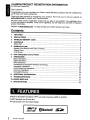
Contents
1.
2.
3.
4.
5.
6.
7.
8.
9.
10.
11.
FEATURES
PRECAUTIONS
HANDLING MEMORY CARD
CONTROLS
MAIN UNIT
NOMENCLATURE
Names of the Buttons and Their Functions
Display Items
LCD Screen
DCP (Detachable Control Panel)
OPERATIONS
Basic Operations
Radio Operations
MP3 Operations
Introduction to Bluetoothqj> Wireless Technology
Handsfree Operations
Audio Streaming Operations
Common Operations
Compatible Devices
ADDITIONAL INFORMATION
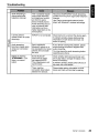
TROUBLESHOOTING
ERROR DISPLAYS
SPECIFICATIONS
2
3
4
5
5
6
6
7
7
8
9
9
10
12
18
20
23
24
29
30
32
35
36
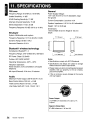
1. FEATURES
• Built in Bluetooth® Handsfree (HFP) and audio streaming (A2DP & AVRCP).
• MP3 playback via SO card slot.
• 728-variable color illuminated design.
RlP3
ID3TAG
2
FB275BT I FB275BTB
oBluetooth
e
S~
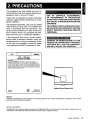
2. PRECAUTIONS
This equipment has been tested and found to
comply with the limits for a Class B digital device,
pursuant to Part 15 of the FCC Rules.
These limits are designed to provide reasonable
protection against harmful interference in a residential installation.
This equipment generates, uses, and can radiate
radio frequency energy and, if not installed and
used in accordance with the instructions, may
cause harmful interference to radio communications. However, there is no guarantee that interference will not occur in a particular installation.
If this equipment does cause harmful interference to radio or television reception, which can
be determined by turning the equipment off and
on, the user is encouraged to consult the dealer
or an experienced radiofTV technician for help.
USE OF CONTROLS, ADJUSTMENTS,
OR PERFORMANCE OF PROCEDURES
OTHER THAN THOSE SPECIFIED HEREIN,
MAY RESULT IN HAZARDOUS RADIATION
EXPOSURE.
THECOMPACTDISCPLAYERSHOULDNOT
BE ADJUSTED OR REPAIRED BY ANYONE
EXCEPT PROPERLY QUALIFIED SERVICE
PERSONNEL.
INFORMATION FOR USERS:
CHANGES OR MODIFICATIONS TO THIS
PRODUCT NOT APPROVED BY THE MANUFACTURER WILL VOID THE WARRANTY
AND WILL VIOLATE FCC APPROVAL.
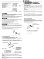
clarion
MODEL
12V= 15Amax
FM 87.5-107.9MHz
FCC ID: Q2Z c::==:::J
THIS DEVICE COMPLIES WITH PART 15 OF THE FCC RULES.
OPERATION IS SUBJECT TO THE FOLLOWING TWO CONDITIONS:
(1) THIS DEVICE MAY NOT CAUSE HARMFUL INTERFERENCE, AND
(2)THIS DEVICE MUST ACCEPT ANY INTERFERENCE RECEIVED,
INCLUDING INTERFERENCE THAT MAY CAUSE UNDESIRED OPERATION.
MANUFACTURED: CLARION MALAYSIA
SERIAL No.
PE-85OOB
276- c::=:::J
Clarion Co. ,Ltd.
MADE IN MALAYSIA
Bottom View of Source Unit
Warning:
Changes or modifications to this equipment not expressly approved by the party responsible for compliance could void the
user's authority to operate the equipment.
SD Logo is a trademark.
The BI'!etoothO word mark and logos are owned by the BluetoothO SIG, Inc. and any use of such marks by Clarion Co. ,Ltd. is
under license. Other trademarks and trade names are those of their respective owners.
FB275BT I FB275BTB
3
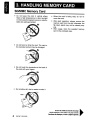
3. HANDLING MEMORY CARD
SD/MMC Memory Card
• Do not leave the card in vehicle where
there is high temperature or direct sunlight
or where electromagnetic waves or electrostatic are easily generated.
• When the card is being read, do not remove the card.
• After eject operation, always remove the
memory card from the slot; otherwise, the
flip down panel may not be closed properly.
• After usage, store the supplied memory
card in the enclosed case.
• Do not bend or drop the card. The card or
the recorded content may be damaged.
--...IIIIfJII'....... No
• Do not touch the terminals on the back of
the card with your fingers.
• Do not allow dirt, dust or water to enter it.
Be sure to unfold and read the nextpage.
VeuilJez deployer et vous referer /a page suivante.
&erci6rese de desplegar y de leer la pagina siguiente.
a
4
FB275BT I FB275BTB
~
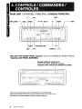
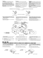
MAIN UNIT / APPAREIL PRINCIPAL / UNlOAD PRINCIPAL
[I]
[RPT]
With the FLIP DOWN PANEL opened I Ouvrez Ie PANNEAU RABATTABLE
I Apertura del PANEL ABATIBLE
SDIMMC MEMORY CARD SLOT
FENTE DE CARTE MEMOIRE SD/MMC
RANURA PARA TARJETA DE MEMORIA SDIMMC
Note: Be sure to unfold this page and refer to the front diagrams as you read each chapter.
Remarque: Veuillez deplier cette page et veils referer aux schlimas Quand veus lisez chaque chapitre.
Nota: Cuando lea los capitulos, despliegue esta pagina y consulte los diagramas.
5
FB275BT I FB275BTB
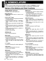
5. N()MENCLATLJRE
Notes:
• Be sure to read this chapter referring to the front diagrams of chapter "4. CONTROLS" on page 5.
• SO is the abbreviation of Secure Digital Card while MMC is the abbreviation of Multimedia card.
Names of the Buttons and Their Functions
SD/MMC MEMORY CARD SLOT
• SO/MMC memory card insertion slot.
[RELEASE] button
• Deeply push in the button to unlock the flip
down panel.
[~/II • ENT] knob
• Adjust the volume by turning the knob clockwise
or counterclockwise.
• Press and hold the knob for 1.5 seconds or
longer to perform auto store in the Radio
mode.
• Play or pause a track while in the SO/BT Audio
mode.
• Press and hold the knob for 1.5 seconds or
longer to perform manual navigation in the SO
mode.
• Perform next level adjustment or selection in
the Adjustment mode.
• Perform various settings.
INTERNAL MIC
• Built-in internal microphone.
[DISP] button
• During SO mode, switch the display indication
in the following order:
Track Name -+ Folder Name -+ Title Tag-+
Album Tag -+ Artist Tag -+ Track Name...
• Press and hold the button for 1.5 seconds or
longer to enter the Adjustment mode.
[~,~] buttons
• Seek a station while in the Radio mode or
select a track when listening to a SO/BT Audio
mode.
• These buttons are also being used to make
various settings.
[1] button
• Restart current track in the SO mode.
[RPT] button
• Perform track repeat play while in the SO
mode.
• Press and hold the button for 1.5 seconds or
longer to perform folder repeat play while in the
SO mode.
[SRC] button
• Press the button to turn on the power.
• Press and hold the button for 1.5 seconds or
longer to turn off the power.
• Switch the Operation mode among the Radio
mode, SO mode, BT Audio mode and AUX
mode.
[ROM] button
• Perform track random play while in the SO
mode.
• Press the button to toggle track random/folder
random/card random/random off while in the
SO mode.
• Press and hold the button for 1.5 seconds or
longer to perform quick random folder play.
[ , ] button
• Accept an incoming call or make outgoing call.
[V], [A] buttons
• Select the folder in the SO mode.
[~] button
• Reject an incoming call or end a call.
• Cancel cu rrent operation.
[DIRECT] buttons
• Store a station into memory or recall it directly
while in the Radio mode.
• Store a telephone number into memory or
recall it directly while in the Telephone mode.
[BND] button
• Switch the band while in the Radio mode.
• Press and hold the button for 1.5 seconds or
longer to toggle seek/manual tuning.
• Play the first track in current folder while in the
SO mode.
• Press and hold the button for 1.5 seconds or
longer to play the first track in the memory
card.
6
FB275BT I FB275BTB
[ISR] button
• Recall ISR radio station in memory.
• Press and hold for 1.5 seconds or longer: Store
current station into ISR memory (Radio mode
only).
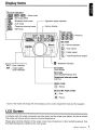
Display Items
Source indication
IEI!I,(iil§,(iilEI : Radio mode
(il[~) : SD mode (MP3)
1m :
Bluetooth Audio mode
r----
Operation status indication
III:!m : AUX mode
".1 :
Telephone Interrupt mode
~-I
Various display
*
: ISR mode
Radio mode
~~
IID,I];I§I,(~),: Preset no.
(~),I];0,I~
SO mode
: Normal playback
: Track repeat
o:
Bluetooth indication
ENT: Enter indication
lSI"
: Instant station
recall indication
1...-
All modes
Clock display
SO mode
Clock display/Playback time
Telephone Interrupt mode
Call time
' - - - - - - - - - - Radio mode
: Stereo
SO and BT Audio mode
f 1&-1 : Play
:0."............,.............<"
~
t~j: Pause
* Some of the modes will change the whole display such as volume, Adjustment mode and file navigation.
LCD Screen
In extreme cold, the screen movement may slow down and the screen may darken, but this is normal.
The screen will recover when it returns to normal temperature.
Please take note that reflection of the screen cover may increase due to direct sunlight exposure, thus
this might decrease the visibility of the LCD screen.
FB275BT I FB275BTB
7
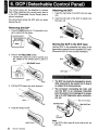
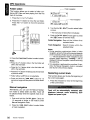
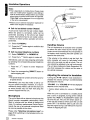
6. DCP (Detachable Control Panel)
The control panel can be detached to prevent
theft. When detaching the control panel, store it
in the DCP (Detachable Control Panel) case to
prevent scratches.
We recommend taking the DCP with you when
leaving the car.
Attaching the DCP
1. Insert the right side of the DCP into the main
unit.
2. Insert the left side of the DCP to attach into
the main unit.
Removing the DCP
1. Press the [SRC] button for 1.5 seconds or longer to switch off the power.
Storing the DCP in the DCP case
Hold the DCP, in the orientation as shown in the
figure below, and put it into the supplied DCP case.
(Ensure the DCP is in the correct orientation.)
2. Press in the [RELEASE] button.
* The flip down panel can only be opened up to
65°, please do not forcibly push to open further.
[RELEASE] button
3. Pull the DCP toward you and remove it.
4. Close the HOLD FLAP.
Note:
• If the DCP is dirty, wipe off the dirt with a soft, dry
cloth only.
8
FB275BT I FB275BTB
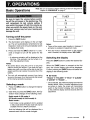
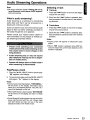
7. OPERATIONS
Basic Operations
Note: Be sure to read this chapter referring to the front diagrams of
chapter "4. CONTROLS" on page 5.
Be sure to lower the volume before switching off the unit power or the ignition key. The
unit remembers its last volume setting. If
you switch the power off with the volume up,
when you switch the power back on, the sudden loud volume may hurt your hearing and
damage the unit.
[
l
SD
Turning on/off the power
1. Press the [SRC] button.
2. The illumination and display on the unit light
up. The unit automatically remembers its last
Operation mode and will automatically switch
to display that mode.
3. Press and hold the [SRC] button for 1.5 seconds or longer to turn off the power for the
unit.
* A welcome animation will be displayed at the
first time. This animation can be turned on or
off in the Adjustment mode.
Notes:
• Be careful about using this unit for a long time
without running the engine. If you drain the car's
battery too much, you may not be able to start the
engine and this can reduce the service life of the
battery.
• The unit will automatically prevent from being
turned on the power for a few seconds after power
off for internal protection purposes.
Selecting a mode
1. Press the [SRC] button to change the Operation mode.
2. Each time you press the [SRC] button, the Operation mode changes in the following order:
Notes:
• There will be screen wipe transition in between if
animation is enabled in Adjustment mode.
• If the SO mode is selected when no SO memory
card is inserted, the display shows "NO CARD".
Switching the display
Press the [DISP] button to select the desired display.
When the [DISP] button is pressed at the first
time, the current display type will be displayed.
Further pressing the [DISP] button will switch the
display in the following order:
•
SO mode
"TRACK" ~ "FOLDER" ~ "TITLE" ~ "ALBUM"
~"ARTIST"~ "TRACK" ...
* Once selected, the preferred display becomes the
display default. When a function adjustment such
as volume is made, the screen will momentarily
switch to that function's display, then revert back
to the preferred display several seconds after the
adjustment.
Radio mode ~ SD mode ~
(BT Audio mode) ~ (AUX mode) ~
Radio mode...
* AUX mode is only available if AUX is enabled
in AOJ mode while BT Audio mode will only be
available if there is A20P connection.
And the following title will be displayed for a
moment each time the mode changes.
FB275BT / FB275BTB
9
Basic Operations
Radio Operations
Adjusting the volume
Listening to the radio
Turning the [ ~/II • ENT ] knob clockwise increases the volume; turning it counterclockwise
decreases the volume.
1. Press the [SRC] button and select the Radio
mode, then the radio will be on.
"VOLUME 0" to "VOLUME 33" will be displayed
depends on the volume level.
*
Factory default setting for volume is "VOLUME
13",
AUX function
This system has AUX RCA input in the rear panel
where you can listen to sounds and music from
external devices connected to this unit.
1. Connect the external music player to the AUX
RCA input.
2. Enable the AUX function in Adjustment mode.
Please refer "Setting AUX function" on page
25 for more details.
3. Press the [SRC] button to select the AUX mode
to activate the AUX function.
Note:
• Volume can be adjusted through the unit.
2. To select a preset band, press the [BND] button, then select one of the preset bands such
as FM1, FM2 or FM3. Every time the [BND]
button is pressed, the display will change as:
FM1 -7 FM2 -7 FM3 -7 FM1...
3. Press the [ ..... , ~] button to tune in the
desired station.
* Initial frequency display is "87.50MHz".
Seek tuning
There are 2 types of seek tuning: OX SEEK and
LOCAL SEEK.
OX SEEK can automatically tune in to receivable
broadcast stations; LOCAL SEEK can tune in to
only broadcast stations with a good reception
sensitivity.
1. Press the [BND] button and select the desired
FM band.
*
Please refer chapter "Common Operations" on
page 24 for more operation controls.
Press and hold the [BNO] button for 1.5 seconds
or longer to switch to Auto Seek mode. Make
sure "SEEK TUNE" is displayed briefly.
2. Press the [ ..... ,~] button to start automatic
station tuning.
When the [~] button is pressed, search
will be performing in the direction of higher frequencies. When the [ ..... ] button is pressed,
search will be performed in the direction of
lower frequencies.
•
OX SEEK
When the [~] button is pressed, search will be
performing in the direction of higher frequencies.
When the [ ..... ] button is pressed, search will be
performed in the direction of lower frequencies.
*
•
When seek tuning starts, "OX" appears in the
display.
LOCAL SEEK
If the button is pressed and held in position for
1.5 seconds or longer, local seek tuning will be
enabled. Broadcast stations with good reception
sensitivity are selected.
* When local seeking starts, "LO" appears in the
display.
10
FB275BT I FB275BTB
Radio Operations
Manual tuning
There are 2 ways available: Quick tuning and
step tuning.
When you are in the step Tuning mode, the frequency changes one step at a time. In the Quick
Tuning mode, you can quickly tune the desired
frequency.
1. Press the [BND] button and select the desired
FM band.
* Press and hold the [BND] button for 1.5 seconds
or longer to switch to Manual Seek mode. Make
sure "MANUAL TUNE" is displayed briefly.
Notes:
• The stations are stored in FM3 even if FM1 or FM2
was chosen for storing stations.
• The auto store procedure may take up to 40 seconds to complete.
Recalling a preset station
A total of 18 preset positions (6-FM1, 6-FM2, 6FM3) exists to store individual radio stations in
memory. Pressing the corresponding [DIRECT]
button recalls the stored radio frequency automatically.
2. Tune into a station.
1. Press the [BND] button and select the desired
FM band.
•
2. Press the corresponding [DIRECT] button to
recall the stored station.
Quick tuning
Press and hold the [ ..... , ~ ] button for 1.5 seconds or longer to begin station tuning.
•
* Press and hold one of the [DIRECT] buttons for
1.5 seconds or longer to store that station into
preset memory.
Step tuning
Press the [ ..... , ~] button to perform manual
tuning.
Preset memory function
Preset memory function can store up to 18 stations:
Six stations for each of FM1, FM2, and FM3.
* Factory default setting is empty for all channels.
Manual memory function
1. Press the [BND] button, to select a band you
want to store in the memory.
2. Press the [ ..... , ~] button to tune into a
desired station.
3. Press and hold one of the [DIRECT] buttons
for 1.5 seconds or longer to store the current
station into preset memory and "SAVED" will
be displayed briefly.
Auto store
Auto store is a function for storing up to 6 strongest stations that are automatically tuned in
sequentially. If 6 receivable stations cannot be
received, a previously stored station remains unoverwritten at the memory position.
1. Push and hold the [~/II • ENT] knob for
1.5 seconds or longer. The stations with good
reception are stored automatically to the preset
channels.
Note:
• If there is no preset channel stored, ". -EMPTY- -" is
displayed briefly and reverts to previous frequency
display.
Instant station recall (lSR)
Instant station recall is a special radio preset that
instantly accesses a favorite radio station at a
touch of a button. The ISR function even operates with the unit in other modes.
•
ISR memory
1. Select the station that you wish to store in ISR
memory during Tuner mode.
2. Press and hold the [ISR] button for 1.5 seconds or longer to store the current station
into memory and "SAVED" will be displayed
briefly.
•
Recalling a station with ISR
In any mode, press the [ISR] button to turn on the
radio function and tune the selected radio station.
"(EIli " appears in the display and the " ISR "
indicator lit on. Press the USR] button again to
return to the previous mode.
Notes:
• ISR mode cannot be accessed during Adjustment!
Manual NavigationlTelephone mode.
• If there is no station stored in ISR, ". -EMPTY· ."
is displayed briefly and reverts to previous mode
display. "ISR" indicator will not be lit on.
FB275BT I FB275BTB
11
MP3 Operations
What is SD/MMC card?
The MultiMediaCard (MMC) and Secure Digital
(SD) are flash memory (non-volatile) card format
that are used to store large capacity of data in
a compact and slim size of media. SD memory
cards are based on the older MultiMediaCard
(MMC) format with additional features such as
write protection switch.
•
Precautions when creating MP3 in SOl
MMC card
• Usable sampling rates and bit rates:
Decode Format
Sampling Rate
(kHz)
• Memory card that can be played are limited to
those recognized as SD or MMC; operation
is not guaranteed with all SD memory card
from all manufacturers. For SD/MMC memory
card compatibility, please consult your nearest
Clarion dealer for more information.
Bit-rate (kbps)
SD/MMC
Format
MPEG 1 and 2 - Layer 3
MPEG-1 : 32, 44.1 , 48
MPEG-2 : 16, 22.05, 24
MPEG-1 : 32 - 320
MPEG-2 : 8 - 160
VBR
FAT12 or FAT16
• To prevent the accidental loss of data, always
back up important data to your computer.
Folder Level limit
• Audio files playable on this unit are limited to
MP3 files. AAC, WMA or other audio formats
are not supported.
Max. Files Support
: 255
Folder Name
: Max. 30 Characters
File Name
: Max. 30 Characters
• This unit doesn't support SDHC (Secure
Digital High Capacity) and SDIO (input/output)
cards.
: 8 Level
Max. Folder Support : 255
•
File extensions
• This unit supports SD memory card up to 2GB
based on SD Association standard.
• Always add a file extension ".MP3" to MP3 file
by using single byte letters. If you add a file
extension other than specified or forget to add
the file extension, the file cannot be played.
What is MP3?
•
Never simply change any file extension to
".MP3" as this will cause unexpected result
and may damage the unit as well. Please use
appropriate audio converter to change to valid
mp3 files.
•
Logical format (File system)
MP3 is an audio compression method and classified into audio layer 3 of MPEG standards. This
audio compression method has penetrated into
PC users and become a standard format. This
MP3 features the original audio data compression to about 12 percent of its initial size with a
high quality sound. This means that several music CDs can be recorded on a SD card to allow a
long listening time*.
* Depends on the SO card storage capacity.
1. When writing MP3 file on a SD/MMC card,
please select "FAT12" or "FAT16" as the
system file format. Please be aware that the
Windows XP will format any volume of 512MB
or larger with FAT32 by default. Thus, if the disk
is using "FAT32" system file format, please
format the disk with "FAT' system file format
which is "FAT16". All the data will be erased
during formatting. Thus, please backup your
data accordingly.
2. The folder name and file name can be displayed as the title during MP3 play but the
title must be within 30 single byte alphabetical
letters and numerals (not including a file extension). Longer name will not be displayed.
12
FB275BT I FB275BTB
MP3 Operations
• Folder structure
1. SO card with a folder having more than 8 hierarchicallevels will be impossible. However,
the following hierarchical structure is recommended.
•
Do not insert memory card other than
specify. It may be impossible to extract
these cards from the unit and such damage
will not be covered by the warranty on this
product. If the memory card is not inserted
easily, there may be another memory card
in the slot or the unit may require service.
•
This unit is designed for playing SOIMMC
card only.
•
Do not forcibly insert the memory card to
the slot with incorrect direction (label side
facing down or reverse direction) as this
will damage the memory card as well as
the SOIMMC MEMORY CARD SLOT.
•
Do not leave a memory card unattended in
an automobile. Exposure to direct sunlight
or high temperatures may cause deformation or other malfunction of the memory
card.
•
When the memory card is subjected to
electrostatic or electric noise, this may
result in the loss of data.
Levell
Level 2
Level 3
[_.oot
(JAlbum
~Fol. ]
Notes:
• "G)" is a number of folders that are limited to
"Number of files or folders" conditions.
• Please use subdirectory/subfolder as recommended and avoid placing all the audio files in the
root directory.
• Number of files or folders
1. Up to at least 255* files can be recognized
per folder.
Up to at least 255* files can be played.
* Entries includes sub-folders and MP3 files.
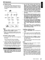
Loading a memory card
1. Press the [RELEASE] button to flip down the
panel.
2. Insert a memory card into the SD/MMC MEMORY CARD SLOT with the label side facing
up.
3. Close the flip down panel. "Loading..." appears
in the display, the memory card plays automatically after loading.
Playback will begin from the first file recorded
on the memory card.
2. Tracks are always sorted alphabetically and
played in that order. (Tracks might not always
be played in the order displayed on the PC.)
Notes:
• Sound will be muted when panel is flipped.
"FLIPPED" will be displayed.
3. Some noise may occur depending on the type
of encoder software used while recording.
• Always insert the memory card fully by pushing it
into the slot. Incomplete insertion may cause the
memory card not be recognized and flip down panel
will not be able to close.
•
Never insert foreign objects into the SOl
MMC memory card slot as it may cause the
unit to break down.
• Depending on the number of tracks and folder
structure recorded, some amount of time may be
required until all tracks are read into the unit. Thus,
please refer chapter "Folder structure" on page
13 for recommended folder hierarchy and optimal
performance. It is best to avoid folders without MP3
files in memory card as this will increase loading
time.
FB275BT I FB275BTB
13
MP3 Operations
-
~~--
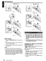
[RELEASE] button
[RELEASE] button
Push to insert
•
Do not remove the memory card when
the panel is not fully flipped as this may
damage the memory card as well as the
unit. Remove the card only when it is fully
flipped.
•
Do not drop the memory card into the space
of the flipped down panel.
Eject function
1. Press the [RELEASE] button to flip down the
panel.
2. Push the memory card slowly to eject and
remove it when ejected.
3. Close the flip down panel after removing the
memory card.
Notes:
• SO memory card may pop out during removal.
• If you remove a memory card such as Micro/Mini SO
and leaving the SD memory card adapter attached
to the unit, it may be hard to remove the adapter
alone from the unit later. Thus, always remove both
the memory card and adapter together if you are
using a memory card adapter.
Listening to a memory card already
loaded in the unit
Press the [SRC] button to select the SD mode.
"1:i:ffiE1" indicater will light on.
When the unit enters the SD mode, play starts
automatically.
*
If there is no memory card loaded, the indication
"NO CARD" appears in the display.
*
If there is no MP3 file is detected, the indication
"NO MP3" appears in the display.
* The mode changes each time the [sRcl button is
presssed.
14
FB275BT I FB275BTB
MP3 Operations
Pausing play
1. Push the [~/II • ENT] knob to pause play.
" .. " appears in the display.
2. To resume track play, push the [~/II • ENT]
knob again. " IB-- " appears in the display.
Display titles
This unit can display title data for the memory
card.
1. Press the [DISP] button to display current title
type.
2. To select the next type, press the [DISP] button
again.
The arrangement is shown below.
Tf;,~ACK
FOLDEf;,~
TITLE
• Supports ID3 Tags v2.3 and v2.4. Earlier ID3 tags
version is ignored but the track is playable.
• Only ASCII characters can be displayed in Tags.
UNICODE ID3 (Chinese, Japanese and etc) is not
supported.
• If ID3 TAG has Japanese, Chinese or other nonsupported characters, "*" will be displayed as
substitution.
• The folder name will be displayed as "(Root)" which
the file allocates in the root directory.
MP3 playing order
When selected for playing folder/track up down
functions, files and folders are always accessed
in alphabetical order. Due to this, the order in
which they are expected to be played may not
match the order in which they are actually played.
If you do not want the tracks to play in alphabetical order, then you can prefix them with 00, 01,
02 etc. to force them to play in a certain order.
Please refer chapter "Folder structure" on page
13 for recommended folder/file hierarchy.
Selecting a track
•
ALBUt'1
Track-up
1. Press the [ ~ ] button to move ahead to the
beginning of the next track.
2. Each time the [ ~ ] button is pressed, the
track advances ahead to the beginning of the
next track.
•
3. Relevant information will be displayed after
showing the title type.
Notes:
• If no Artist information, "NO ARTIST' will be displayed.
Track-down
1. Press the [ ..... ] button to move to the beginning of the previous track.
2. Each time the [ ..... ] button is pressed, playback proceeds to previous track in the reverse
direction.
• If a MP3 file encode with ID3 TAG header but not
consist of any TAG information, "unknown" will be
displayed and change according to the following
display:
Notes:
• Previous track across multiple sub-folders may not
be always return to the previous song you listen as
it will return to the last valid MP3 files of the parent
folder.
- If no Album information, the folder name will be
displayed.
• Fast forward/fast backward is not supported in this
unit.
- If no Title information, the filename will be displayed.
FB275BT I FB275BTB
15
MP3 Operations
. --.--L- FOI~er
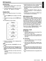
Folder select
This function allows you to select a folder containing MP3 files and start playing from the first
track in the folder.
1. Press the [.A.] or [ ......... ] button.
2. Press the [.A.] button to move the next folder.
Press the [ ......... ] button to move the previous
folder.
~ ( F.~OCI t )
navigation
~l
I Fl'::lin'3Pi ck I
r-:::~'''--~--''--f-_.''- Track navigation
I
I•.
F.~oo t ...
.J l
I.- F 1':::1 i rr3P i c k ~
3. Turn the [ ~/II • ENT] knob to select folder
or track.
* The track play will take effect immediately.
4. Push the [~/II • ENT] knob again or press
the [ ~ ] button to exit the mode.
Folder Navigation: Search the folders that
contains tracks.
Track Navigation : Search tracks within the
selected folder.
'0
3. Press the [ ..... , ~ ] button to select a track.
Notes:
• Press the [.A.] button while in the final folder will
shift to the first folder.
• Press the [ ......... ] button while in the first folder will
shift to the last folder.
Notes:
• During searching next/previous folder in folder
navigation, amount of time will be required depends
on the complexity of folder structure. Animated dots
"....." may be appeared in folder navigation during
complex folder searching. "Loading..." will be
displayed if Manual Navigation mode is exit during
this searching.
• If no operation is performed for more than 10 seconds, the Manual Navigation mode is cancelled
and returns to the previous display.
• Press the [......... ] button will always play the last track
of previous folder.
Restarting current track
• Folder without a MP3 file is not selectable.
This function allows user to play the beginning of
the current song again.
• Press and hold the [ ..... , ~ ] button for 1.5
seconds or longer will also perform as folder down/
up.
1. Press the [1] button to move to the beginning
of the current track.
Manual navigation
Alternatively, you can use the Manual Navigation mode to select folder and files. Track will
be played directly when the specific track is selected.
1. Push and hold the [ ~/II • ENT] knob for
1.5 seconds or longer in SO mode to enter
Manual Navigation mode.
2. Press the [ ..... , ~] button to select folder
or track navigation.
16
FB275BT I FB275BTB
Track will be automatically restarted after
telephone interrupt, audio streaming, DCP
flipped and power cycle.
MP3 Operations
Top function
Return to the first track of the memory card or
the folder currently being played back, and start
playing.
1. Press the [BNO] button to play from the first
track of the current folder.
2. Press and hold [BNO] button for 1.5 seconds
or longer to play the first track of the memory
card.
Note:
• These operations will cancel Track Repeat play and
all Random modes.
Note:
• This function will cancel other previous special playback functions such as track repeat and Random
mode.
Random mode
There are 3 types of Random mode. When the
[ROM] button is pressed at the first time, the current Random mode will be displayed. Further
pressing the [ROM] button will switch the Random mode in the following order:
"ROM TRACK"
~
Special playback functions
"ROM FOLDER"
By default, all special playback functions are
turned off and" ...... " will be displayed.
"ROM CARD"
All the special playback functions will be memorized once activated (except Track repeat play)
even after power off.
"ROM OFF"
~
~
The " ~.i " indicator lights in the display.
Repeat mode
• Track repeat play
This function allows you to play the current track
repeatedly.
1. Press the [RPT] button to perform track repeat
play.
2. Press the [RPT] button again to cancel track
repeat play.
The " ~ " indicator lights in the display when
track repeat play is enabled.
• Track random play
This function allows you to play the tracks of current folder randomly.
1. Press the [ROM] button to select "ROM
TRACK".
Notes:
• It will go to next folder after all the tracks in that
folder have been played. However, this will depend
on folder repeat setting.
• Any track/folder selection will always perform as
next random track/folder.
Note:
• Any track/folder selection, card changing and power
cycle will cancel track repeat play.
•
•
This function allows you to play all the tracks alphabetically in a random folder.
Folder repeat play
Folder random play
This function allows you to play all tracks in the
current folder repeatedly.
1. Press the [ROM] button to select "ROM
FOLDER".
1. Press and hold the [RPT] button for 1.5 seconds or longer to perform folder repeat play.
"RPT FLOR ON" will be displayed briefly.
Note:
• This function will require some amount of time
depends on the complexity of folder hierarchy.
Always use the folder hierarchy as recommened in
chapter "Folder structure" on page 13 for optimal
performance.
2. Press and hold the [RPT] button for 1.5 seconds or longer to cancel folder repeat play.
"RPT FLOR OFF" will be displayed briefly.
G:.I "
The"
indicator lights in the display when
folder repeat play is enabled.
FB275BT I FB275BTB
17
Introduction to Bluetooth®
Wireless Technology
MP3 Operations
• Card random play
This function allows you to play all the tracks of
all the folders in a random order.
1. Press the [ROM] button to select "ROM
CARD".
Notes:
• This function will require some amount of time
depends on the complexity of folder hierarchy.
Always use the folder hierarchy as recommened in
chapter "Folder structure" on page 13 for optimal
performance.
• Any track/folder selection will always perform as
next random track/folder.
• To cancel random play
1. Press the [ROM] button to select "ROM
OFF".
•
Quick random folder play
This function will perform a single jump to a random folder but do not affect current Random or
Folder Repeat settings.
1. Press and hold the [ROM] button for 1.5
seconds or longer to perform quick random
folder play.
Special playback priority
The icon will be displayed according to the selected special playback with the following priorities. It will return to previous special playback
setting after the current special playback function
is turned off.
~
~
~
......
18
FB275BT / FB275BTB
Track Repeat
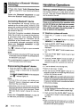
What is Bluetooth® wireless
technology?
Bluetooth@ wireless technology is a radio technology that connects devices, such as mobile
phones and headsets, without wires or cords
over a short distance of approximately 10 meters
(approx. 33 feet). Get more information at www.
bluetooth.com.
What is Bluetooth® wireless
profiles?
Bluetooth@ wireless profiles are the different ways
that Bluetoot~ devices communicate with other
devices. Bluetoot~ phones normally support the
hands-free profile (HFP). In order to support a
certain profiles, a phone manufacturer must
implement certain mandatory features within the
phone's software. The followings are the currently supported profiles for the main unit:
• Hands-Free Profile (HFP)
This is commonly used to allow car hands-free
kits to communicate with mobile phones in the
car. The Bluetoottr car kits allow users with Bluetooth-equipped mobile phones to make use of
some of the phone's features.
• Advanced Audio Distribution Profile
(A2DP)
This allows you to send CD quality stereo music
from external audio player to car stereo without
wires. A2DP is able to provide crystal clear music
without the hassle of plugging cables. Bluetoottr
Wireless Technology with A2DP makes mobile
phones, pda's and computers capable of streaming music.
Random Mode
Folder Repeat
Normal Play
• Audio Video Remote Control Profile
(AVRCP)
This enables music from Bluetooth® audio player
to be controlled remotely. AVRCP allows some
basic playback control functions such as play/
pause, volume up/down and next/previous track
to a Bluetoot~ audio player.
Introduction to Bluetooth® Wireless Technology
What is pairing?
With a mobile phone featuring Bluetooth® technology, you must 'pair' the main unit with the
phonelBluetooth® audio device before you use it
for the first time.
Notes:
• Please make sure your mobile phone supports the
HFP profile.
• Always make sure the Bluetooth® Operation mode
in the phone is on when using this car handsfree.
Pairing creates a unique and encrypted link between two Bluetooth® devices and lets them communicate with each other eliminating the need
to repeat the pairing process during future use.
Bluetooth® devices will not work if the devices
have not been paired. This car stereo is able to
hold up to 8 devices of pairing information.
• Any further connection attempts by other devices
to connect as HFP partner are rejected until the
current device is disconnected. Please refer your
mobile phone owner's manual for disconnecting
device.
What is passkey?
• Please refer chapter "Handsfree Operations" on
page 20 for telephone function.
Passkey or PIN is a code that you enter on your
mobile phone to pair it with the main unit. This
makes your phonelBluetooth® audio device and
the main unit recognizes each other and automatically works together. The default passkey for
this unit is '0000'.
Pairing with a mobile phone
1. Enable pairing mode in the car stereo. Please
refer "Adding a new device (Pairing mode)"
on page 27 for more details.
• Up to the first 8 characters of device name can
be supported. If device name is not obtained,
Bluetooth® address of the device will be used as
default.
Pairing with an external Bluetooth®
audio player (A2DP support)
1. Enable pairing mode in the car stereo. Please
refer "Adding a new device (Pairing mode)"
on page 27 for more details.
2. Set the Bluetooth® audio player in Pairing
mode. Please check your audio player owner's
manual for further details.
2. Activate Bluetooth® on your mobile phone.
Please check your mobile phone owner's
manual for further details.
3. The display automatically switches to BT Audio
mode and start playing music upon successfully pairing and connection. Connection can
be established in any source mode.
3. Search for new Bluetooth® device on the mobile
phone. The car stereo's name is "CLARION_
FB275".
Notes:
• Please make sure your Bluetooth® audio player
supports the A2DP and AVRCP profiles.
4. When attempting to connect to the car stereo,
the mobile phone will prompt for a passkey,
enter the PIN: "0000".
5. Device name will be displayed for editing after
successful pairing. Please refer "Editing a
device name" step 3 onwards on page 27 for
more details.
6. The display returns to previous mode after a
few seconds.
7. Any incoming call will be automatically diverted
to the car stereo once connection is established.
• Any further connection attempts by other devices
to connect as A2DP/AVRCP partner are rejected
until the current device is disconnected.
• You do not have to enter a dedicated pin code
for pairing these two devices (Only applicable to
Clarion products such as Aux Bluetooth® Transmitter), as you do with a mobile phone. However, for
other A2DP devices, you may need to enter "0000"
for the pin code in those devices.
• The same device may connect as both A2DPI
AVRCP and HFP partner. This normally happens
to mobile phone with wireless music streaming
capability. However, using the same device will
cause the A2DP/AVRCP to be disconnected when
there is an incoming call or making a call. User may
need to manually resume playback via audio player
in phone depends on the type of phones. However,
some phones will automatically resume to BT Audio
mode after telephone interrupt.
FB275BT I FB275BTB
19
Introduction to Bluetooth® Wireless
Technology
• Please refer chapter "Audio Streaming Operations" on page 23 for music streaming functionality.
Please refer "Bluetooth@ adjustment" on page
26 for other Bluetooth® related adjustment.
Connecting Bluetooth® device
Your device/phone will normally connect automatically to the unit after pairing. However, some
phones will not allow automatic connection to the
unit after pairing; please use the phone to manually connect to the unit.
If Automatic Connection is enabled in Adjustment
mode, the unit will try to connect to the previously connected phone when entering Telephone
mode or during power up. Connection can be
established at any Source mode. If connection
is unsuccessful, automatic connection will stop.
Please refer "Automatic connection" on page
27 to enable this feature.
The" 8) " indicator will light on upon successful
connection.
Notes:
• Auto connection only works for HFP. User may need
to manually connect for A2DP. This will depends on
the Bluetooth® audio player.
Handsfree Operations
Storing a preset telephone numbers
This function allows you to make direct call from
the unit. There are 6 preset telephone numbers
can be stored in the unit.
Please avoid performing this operation while
you are driving as you may lose your concentration on the road. Always be sure to park
your vehicle and apply the parking brake in
order to perform this operation.
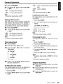
• Telephone numbers edit mode
1. Press the [ r ] button to enter Telephone
mode.
2. Press the [ ..... , ~ ] button to select
"MEMORY 1" to "MEMORY 6".
3. Push the [~/II· ENT] knob to edit the numbers. A blinking cursor on current digit will be
displayed.
4. Turn the [~/II . ENT] knob to select a number.
5. Push the [ ~/II • ENT] knob to go to next
number input.
• It is recommended to connect to mobile phone
(HFP) first before other A2DP device.
6. Push the [ ~/II· ENT ] knob at a blank or
the last 16th digit (" ..... " indicator will be displayed) will store the numbers into memory.
Disconnecting Bluetooth® device
Notes:
• "+" can be allowed in the first digit only.
1. Press and hold the [ ~] button for 1.5 seconds or longer to disconnect all Bluetooth@
devices.
"CLO§lNG CONNECTIONS" will be displayed
and" U " indicator lights off.
Notes:
• Turning off the unit power and deleting any
Bluetooth@ device in Adjustment mode will also
disconnect the current device.
• Alternatively, user can use the phone to manually
disconnect the device. However some devices will
automatically reconnect once disconnect. Please
refer your device owner's manual for more details.
Please refer "Compatible Devices" on page 29
to make sure your device is compatible.
• Maximum digit range: 16 digits.
• Push and hold the [~/II . ENT] knob for 1.5
seconds or longer at a non-blank digit will store the
numbers into memory as well.
• Press the [ ~ ] button at anytime will cancel current
operation and exit the Edit mode without saving the
numbers. If no operation is performed for more than
10 seconds, the Edit mode is cancelled and returns
to the previous display.
• Clearing all digits
1. During Telephone Numbers Edit mode, turn the
[~/II· ENT] knob to select a blank digit.
2. Push and hold the [~/II • ENT] knob for
1.5 seconds or longer to clear all digits on the
right side.
Note:
• Digits on the left side will remain as it is. In order to
clear all the digits, always select the first character
and perform the above operation.
20
FB275BT / FB275BTB
Handsfree Operations
•
Deleting a digit
•
Ending a call
1. During Telephone Numbers Edit mode, turn the
[./11· ENT] knob to select a blank digit.
This function allows you to end a call conversation directly from the car stereo.
2. Push the [ ./11 . ENT] knob to delete current digit.
1. Press the [ ~ ] button to end the call.
2. The display returns to previous mode.
Note:
• Digits on the right side (if there is any) will be shifted
to the left.
Note:
• "CALL END" will be displayed when ending a
conversation.
Incoming call
Whenever your car stereo is operating, the car
stereo is in standby mode awaiting the next call,
when an incoming call arrives the car stereo will
mute automatically and the ring tone is reproduced through your car's speaker.
The Car stereo will temporarily switch to Telephone Interrupt mode and caller ID will be displayed in the car stereo.
Notes:
• Car stereo will be automatically set as default
speaker output everytime when there is an incoming call.
• Some phones choose to present the audio despite
being told to route it to the car stereo. This duplication of audio is a device problem/feature but does
not impair functionality.
• During incoming call, caller ID and "Calling..." will
be displayed. Caller ID and CLIP (Calling Line
Identification Presentation) is dependent on mobile
phone and service provider. However, incoming call
with private telephone numbers (CLlR- Calling Line
Identification Restriction) will not be displayed.
• Answering a call
Alternatively, you may also answer/reject/end the
call by using your phone's keypad. However, it
is recommended to always perform those operations from the main unit.
Making a call
There are few ways to make outgoing call.
If no phone is connected, the car stereo will not
be able to make an outgoing call. The car stereo
will try to reconnect to the last connected device if
Auto Connection is enabled in Adjustment mode.
This is dependent on mobile phones.
Please make sure your phone is connected with
the"
indicator light is on.
0"
There are 2 display icons at the top row of display when entering Telephone mode.
Ir." : Call can be activated.
•
1. Press the [ r ] button to enter Telephone
mode.
2. Press the [ ..... , ~] to select the following
"VOICEDIAL" ~ "LN REDIAL" ~
"MEMORY 1" ~ "MEMORY 2" ~
"MEMORY 3" ~"MEMORY 4" ~
"MEMORY 5" ~ "MEMORY 6"
User can answer an incoming call directly from
the car stereo.
1. Press the [ r ] button to pick up an incoming
call.
2. The display switch to Telephone Interrupt mode.
Notes:
• During conversation, ",,".'11" and call time elapsed
will be displayed.
• During an incoming call, some phones may automatically pick up the call when it connects to this
unit.
: Call cannot be activated. Please connect
your phone.
3. Press the [ r ] button again to perform outgoing call.
Note:
• "Dialing" will be displayed when making a call.
Telephone numbers will be displayed if using the
preset telephone numbers dialing.
•
Call via voice dialing
2-1. Select "VOICEDIAL"
•
Rejecting a call
This function allows you to reject an incoming
call directly from the car stereo.
1. Press the [ ~] button to reject an incoming
call.
2. The display returns to previous mode.
r ]button again to activate
3-1. Press the [
voice dialing.
3-2. Speak the contact name clearly towards the
internal/external microphone to perform voice
dialing.
FB275BT/FB275BTB
21
Handsfree Operations
I
Notes:
• This is dependent on mobile phone. Please make
sure your mobile phone supports voice dialing in
order to use this feature. Please refer to your mobile
phone owner's manual if this function is supported.
"CALL FAIL" will be displayed if it is not supported
or the call is unsuccessful.
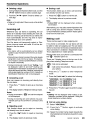
Microphone
/
External Microphone
(Included)
• Please use an external microphone (optional) for
better voice reception if necessary.
~-1
L-.... Fix the Microphone
to the car visor
•
Call via last dialed number (Redial)
A call can be made with the last number dialed.
When the phone is connected, redial can be
performed according to the phone last dialed
number. Each phone has its own redial number.
If there's no redial number, operation will not be
performed.
2-1. Select "LN REDIAL"
3-1. Press the [r] button again to redial the last
dialed number.
•
Call via preset telephone numbers
2-1. Select "MEMORY 1" to "MEMORY 6".
3-1. Press the [ r ] button again to make call.
Alternatively, user can make outgoing call directly
by pressing the corresponding preset telephone
numbers.
1. Press the [
mode.
r ] button to enter Telephone
2. Press the corresponding [DIRECT] button to
make outgoing call.
Note:
• The preset telephone numbers will be the same for
all paired devices.
Alternatively, you may also make a call by using your phone's keypad. However, it is recommended to always make a call from the main unit
as some phones may not work well using the
phone's keypad with this unit.
Microphone
The unit is fitted with an internal microphone that
should provide acceptable performance when
fitted to vehicles with low levels of background
noise. For optimum performance Clarion recommends the use of an external microphone fitted
as near as possible to the driver.
Please refer "Selecting microphone input" on
page 28 for switching to internal/external the microphone.
22
FB275BT I FB275BTB
Handfree Volume
The unit implements an acoustic echo canceller
to reduce the echo heard by the remote caller.
Under normal circumstances the unit operates in
full-duplex mode meaning that both parties can
speak at the same time.
If the volume in the vehicle is set too high, the
echo canceller will revert to half-duplex mode
when only one party can talk at a time. The volume should be adjusted to be just loud enough.
The unit also implements Noise Dependent Volume that increases the volume as the noise in
the vehicle increases.
Adjusting the volume for handsfree
Turning the [ ~/II • ENT ] knob clockwise increases the volume; turning it counterclockwise
decreases the volume.
"VOLUME 1" to "VOLUME 16" will be displayed
depends on the volume level.
*
Factory default setting for volume is "VOLUME
8".
When the unit is connected to a mobile phone
and a call is in progress, turning off the vehicle
ignition key ("ACC" or ACCESSORY) switch will
not end the call. The unit will remain active until the call has ended at which point the unit will
power OFF. It is therefore safe to pull over and
stop the engine during a call without the inconvenience of dropping the call.
Audio Streaming Operations
Note:
• Be sure to read the chapter "Pairing with an external Bluetooth® audio player (A2DP support)"
before proceeding.
What is audio streaming?
Audio streaming is a technique for transferring
audio data such that it can be processed as a
steady and continuous stream.
Users can stream music from their external audio
player to their car stereo wirelessly and listen to
the tracks through the car's speakers.
Please consult your nearest Clarion dealer for
more information on the product of wireless audio streaming transmitter offered.
•
Please avoid operating your connected
mobile phone while audio streaming as this
may cause noise or sound choppy on the
song playback.
•
Audio streaming mayor may not resume
after telephone interrupt as this is dependent on mobile phone.
Selecting a track
• Track-up
1. Press the [ ~] button to move to the beginning of the next track.
2. Each time the [ ~] button is pressed, playback proceeds to another track in the advancing direction.
• Track-down
1. Press the [ ..... ] button to move the to beginning of the previous track.
2. Each time the [ ..... ] button is pressed, playback proceeds to previous track in the reverse
direction.
Notes:
• Playing order will depend on Bluetooth® audio
player.
• When [ ..... ] button is pressed, some A2DP devices will restart the current track depends on the
duration of playback.
• System will always return to Radio mode if
audio streaming is disconnected.
Play/Pause a track
1. Push the [~/II • ENT] knob to pause play.
" II " appears in the display.
2. To resume track play, push the [~/II • ENT]
knob again. " I&-- " appears in the display.
Notes:
• During music streaming playback, "STREAMING..."
will be shown on the display. Information about
tracks (e.g. the elapsed playtime, song title, etc.)
cannot be displayed on this unit.
• When A2DP device is disconnected, "NO STREAM"
will be shown on the display and return to Radio
mode.
• Some Bluetooth® audio players may not have play/
pause synchronized with this unit. Please make
sure both device and main unit are in the same
play/pause status in BT AUDIO mode.
FB275BT/FB275BTB
~:J
Common Operations
Adjustment mode
•
There are 5 categories of Adjusment mode:
.-G). Select "TREBLE".
•
Audio mode
(Bass, Treble, Balance, Fader and Loudness)
o-G). Turn
•
Additional Source mode (AU X Input)
•
Clock* Adjustment mode
•
Display* Adjustment mode
Adjusting the treble
[~/II· ENT] knobclockwiseemphasizes the treble; turning it counterclockwise
attenuates the treble.
Notes:
• The factory default setting is "0".
• The value range is -7 to +7.
• Bluetooth®* Adjustment mode
* Item that has 2nd level adjustment
During Telephone Interrupt mode, only Balance
and Fader can be adjusted. Adjustment mode is
unaccessible during Telephone mode and vice
versa.
•
8-G). Select "BALANCE".
.-G). Turn the [ ~/II • ENT ] knob clockwise
emphasizes the sound from the right speaker; turning it counterclockwise emphasizes
the sound from the left speaker.
O. Press and
hold the [DISP] button for 1.5 seconds or longer to enter the adjustment selection
display.
The display changes as follows:
"RIGHT XX" will be displayed where "XX" is
the value from 1 to 12.
8. Press the [..... ,~] button to select the "item
name".
"BASS" ~ "TREBLE" ~ "BALANCE" ~
"FADER" ~ "LOUDNESS" ~
"AUX INPUT" ~ "CLOCK" ~
"DISPLAY" ~ "BLUETOOTH"
CD. Push the [ ~/II • ENT ] knob to enter 2nd
level adjustment or turn the [~/II • ENT]
knob to select the "desired setting value"
depends on the selected item.
Notes:
• A" ...... " will be displayed and" eNT" will light on
when an item has 2nd level adjustment.
"LEFT XX" will be displayed where "XX" is
the value from 1 to 12.
Notes:
• When Balance is 0, "CENTER" will be displayed
instead.
• The factory default setting is "CENTER".
•
[~/II • ENT] knob clockwise emphasizes the sound from the front speakers;
turning it counterclockwise emphasizes the
sound from the rear speakers.
o-<D Turn the
The display changes as follows:
"FRONT XX" will be displayed where "XX" is
the value from 1 to 12.
• If no operation is performed for more than 10
seconds, the Adjustment mode is cancelled and
returns to the previous display.
•
Adjusting the bass
8-G)· Select "BASS".
o-G). Turn the
"REAR XX" will be displayed where "XX" is
the value from 1 to 12.
Notes:
• When Fader is 0, "CENTER" will be displayed
instead.
• The factory default setting is "CENTER".
[~/II· ENT ] knob clockwise
emphasizes the bass; turning it counterclockwise attenuates the bass.
Notes:
• The factory default setting is "0".
• The value range is -7 to +7.
24
Adjusting the fader
8-G). Select "FADER".
• After completing settings, press and hold the [~l
button for 1.5 seconds or longer to return to the
previous mode.
Audio mode
Adjusting the balance
FB275BT I FB275BTB
•
Adjusting the loudness
The loudness effect does not adjust the low
sound area like the normal sound adjustment
function, but emphasizes the deep bass sound
area to provide you with a dynamic sound.
Common Operations
o-<!> Select "lOUDNESS".
• -<!> Turn the [~/II • ENT] knob to select "ON"
or "OFF".
• ON
• ON
: Clock is enabled and manually set by
user.
• OFF : Clock is disabled.
: Loudness effect enabled.
• OFF : Loudness effect disabled.
Note:
• The factory default setting is "OFF".
Note:
• The factory default setting is "OFF".
•
Setting AUX function
1. Select "ClK MODE".
This option allows user to enable or disable the
AUX function. AUX function will be available in
source mode selection if turned on. Otherwise, it
will be hidden from the source mode selection .
2. Turn the [ ~/II • ENT] knob to select the
options.
• -G). Select
This setting allows user to select either 12 or 24
hour system.
r
"12 HR"
e
"24 HR"
J
"AUX INPUT".
8-G)· Turn the [~/II
• ENT] knob to select "ON"
.12 HR : 12 hour mode.
• 24 HR : 24 hour mode.
or "OFF".
• ON
Setting the clock mode
: Aux function is turned on.
• OFF : Aux function is turned off.
Note:
• The factory default setting is "12 HR".
Note:
• The factory default setting is "OFF".
•
Clock adjustment
1. Select "ClK SET".
@)-<D. Select "CLOCK".
2. Push the [~/II • ENT] knob.
8-<D. Push the [~/II • ENT] knob.
3. Press the [ ..... , ~ ] button to select the
hour or the minute.
8-(2). Press the [ ..... , ~] button to select the
"item name".
"ClK EN"
Adjusting the clock
This adjustment allows the clock to be set by
user.
4. Turn the [ ~/II • ENT ] knob to set the correct time.
t
5. Press the [~] button to exit the setting.
t
Notes:
• The factory default setting is "00:00" for 24 hour
mode.
"ClKMODE"
"ClK SET"
• The clock is updated in realtime.
8-®. Push or turn the [~/II· ENT] knob depends on selected item.
Display adjustment
•
@)-<D. Press the [ ..... , ~] button and select
"DISPLAY".
Setting the clock enable
This setting allows the clock to be displayed at
the bottom of display in all source modes.
8-<D. Push the [~/II • ENT] knob to enter next
level adjustment.
1. Select "ClK EN".
.-(g). Press the [ ..... ,~] button to select the
2. Turn the [ ~/II • ENT] knob to select "ON"
or "OFF".
"item name".
FB275BT I FB275BTB
25
Common Operations
•
"SCROLL"
t
1. Select "COLOR".
"CONTRAST"
2. Turn the [ .-/11 • ENT] knob to select the
color, the type changes in the following orders:
t
"ILLUM"
t
COL. SCAN ~ OFF ~ BLUE ~
SURF BLUE ~WHITE ~ AQUA ~
GREEN ~ LIME ~ ORANGE ~ RED
~ PINK ~ PALE PINK ~ VIOLET ~
PURPLE~USER COL.~COL. SCAN ...
"COLOR"
t
"USER COL."
t
"ANIMATION"
e-@· Push or turn the [ .-/11 • ENT] knob de-
pends on selected item.
•
Setting the method for title scroll
Set how to scroll in MP3 title.
* The factory default setting is "ON".
1. Select "SCROLL".
2. Turn the ['-111 . ENT] knob to select "ON"
or "OFF".
• ON : To scroll continunously.
• OFF : Scroll function is disabled. It will only
scroll for once.
•
Adjusting the display contrast
You can adjust the display contrast to match the
angle of installation of the unit.
* The factory default setting is "9".
(Adjustment level: 0 to 14)
2. Turn the ['-111 • ENT] knob to adjust the
contrast.
Adjusting the display and line illumination
You can adjust the display illuminations (Display
backlight intensity) at night (key illumination on).
The adjustment level is from 1 to 9.
* The factory default setting
for key illumination on
is "3".
1. Select "ILLUM".
2. Turn the [ .-/11 • ENT ] knob to adjust the
illumination.
Notes:
• The new settings will be stored in memory.
• Display illumination is fixed at "9" for key illumination
off (Daytime). "N/A" will be displayed.
26
FB275BT I FB275BTB
• Setting user color mode
1. Select "USER COL".
2. Turn the [ .-/11 • ENT ] knob to enter the
setting.
3. Press the [ ..... , ~] button to move the
cursor for adjusting the R, G or B value. The
value of R is adjustable by default.
4. Turn the ['-/11 • ENT] knob to select from 0
to 8. Adjustment will be updated in realtime.
Note:
• The factory default setting for user color R, G and
B (R: red, G: green, B: blue) are "S".
•
Setting the animation effect
You can turn on or off the animation effect in this
unit.
1. Select "ANIMATION".
2. Turn the [ .-/11 • ENT] knob to select "ON"
or "OFF".
• ON
1. Select "CONTRAST".
•
Setting the color line illumination
: Welcome animation and screen wipe
transition at Source mode are enabled.
• OFF : Animation effect is disabled.
Bluetooth adjustment
fl
8-<D· Press the [ ..... , ~] button and select
"BLUETOOTH".
6)-(1). Push the ['-/11 . ENT] knob.
e-®. Press the [ ..... , ~ ] button to select the
"item name".
Common Operations
•
"ADD DEV."
t
1. Select "DEL. DEV.".
"EDIT DEV."
2. Push the [~/II • ENT] knob.
t
"DEL. DEV."
t
"AUTO CONN"
3. Turn the [~/II • ENT] knob to select a device
to be deleted.
4. Push the [~/II • ENT] knob. A delete confirmation is prompted.
t
"MIC"
O-®· Push or turn the
5. Turn the [~/II • ENT] knob to select "YES"
or "NO".
[~/II • ENT] knob de-
pends on selected item.
•
Adding a new device (Pairing mode)
1. Select "ADD DEV.".
2. Push the [~/II • ENT] knob.
* The" 0 "indicator will be blinking. The display
shows "Pairing..." and the car stereo is currently
in Pairing mode.
Note:
• The pairing timeout is 3 minutes.
•
Deleting a device
Editing a device name
1. Select "EDIT DEV.".
2. Push the [~/II • ENT] knob.
* The display shows the device name.
[DEI..r::-T~AtI1E
"~~l
PHONE-\
Device name
3. Turn the [ ~/II • ENT] knob to edit a character.
4. Press the [~] button or push [~/II • ENT]
knob to go to next character. Press the [~]
button to return to previous character.
6. Push the [~/II • ENT] knob to confirm the
selection.
Notes:
• If there is no device connected, "(no devices)" will
be shown in the display.
• "All" option will be available if there is more than
one device connected.
• Deleting pairing information in the main unit only
stops the unit from being connect to the other device. It does not stop the other device from trying
to connect to main unit. Please delete the pairing
information of the main unit from the phone/device
as well. Always make sure pairing information on
both device and main unit have been deleted before
starting a new pairing activity.
• Deleting a device will disconnect any current
Bluetooth® connection. User will need to manually
re-connect if necessary.
•
Automatic connection
This function allows the unit to be connected automatically with previously connected device during power up or entering Telephone mode. The
Bluetooth® wireless function in your phone has to
be turned on to establish automatic connection.
1. Select "AUTO CONN".
2. Turn the [ ~/II • ENT ] knob to select "ON"
or "OFF".
5. Push the [~/II . ENT] knob at the last blank
character to store the name.
• ON
Notes:
• Push and hold the [ ~/II • ENT ] knob for 1.5
seconds or longer at any position will store the
name as well.
Notes:
• The factory default setting is "OFF".
• If there is no device connected, "(no devices)" will
be shown in the display.
: Auto connection enabled.
• OFF : Auto connection disabled.
• Please enable this feature only if your phone is
supported.
FB275BT I FB275BTB
27
Common Operations
• Selecting microphone input
The clock time reset is done with the following
steps.
1. Select "MIC".
2. Turn the [~/II· ENT] knob to select one of
the following:
-INTERNAL: Built-in microphone will be used.
- EXTERNAL: An external microphone will be
used.
1. Turn off the power.
2. Press the [RELEASE] button and remove the
DCP.
3. Press the reset button with a thin rod.
~Reset button
Note:
- The factory default setting is "INTERNAL".
)
System Menu
1. Press and hold [~] and [ ..... ] buttons simultaneously for 1.5 seconds or longer.
2. Press the [ ..... , ~ ] button to select an item.
["VERSION"
e
"FACT. RST"
J
3. Press the [~] button to exit the menu.
• Checking the unit version
2-1. Select "VERSION".
• Restoring to factory default setting
This function allows user to restore the unit to the
factory default setting.
2-1. Select "FACT. RST".
2-2. Push the [~/II • ENT] knob. A reset confirmation is prompted.
2-3. Turnthe[~/II· ENT] knob to select "YES"
or "NO".
2-4. Push the [~/II • ENT] knob to confirm the
selection.
Notes:
- All pairing information and preset memories will be
cleared. User will have to manually perform those
setting again.
- Once reset, system will automatically turn off and
re-power on.
- Clock time will not be reset with this operation.
28
FB275BT I FB275BTB
Compatible Devices
Supported phones with Bluetooth®
wireless technology
Make sure your mobile phone supports the following Bluetooth® profile:
- HFP (Handsfree for mobile phone)
Optional profiles for audio streaming in mobile
phone:
- A2DP (Stereo music streaming)
- AVRCP (Remote control function)
Please check your phone's specification for supported profiles. Features supported for each profile vary from product to product. To ensure your
device will work correctly with this unit, please
consult your nearest Clarion dealer for your
phone compatibilities.
Supported external audio player
with Bluetooth® wireless technology
This car stereo is compatible with Clarion
Bluetooth® Audio Transmitter (DGL370/373) and
Cradle for iPod (BC001 N/BC002M/BC003V).
Please consult your nearest Clarion dealer for
the product offer.
Operation is not guaranteed with all the Bluetooth®
audio players that supports A2DP/AVRCP from
other manufacturers.
FB275BT I FB275BTB
29
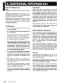
8. ADDITIONAL INFORMATION
Safe and efficient use
Installation
Note:
Please note that only authorized personnel
should install the car stereo. Please check with
your car dealer for recommendations on professional installation engineers. Check with your car
manufacturer's representative to be sure that all
equipment for the car stereo, including additional
accessories, is placed in a safe location. If your
car is equipped with an air bag, check that the
handsfree equipment does not interfere with its
function.
• Read this information before using your car stereo.
Changes or modifications to this product not expressly approved by Clarion may void the user's
authority to operate the equipment.
Please check for any exceptions, due to national
requirements or limitations, in usage of equipment with Bluetooth® wirelesss technology before using this product.
Product care
•
Do not expose your product to liquid or moisture or to humidity.
•
Do not expose your product to extreme high or
low temperatures.
•
Do not expose your product to lit candles,
cigarettes, or cigars, or to open flames etc.
•
Do not drop, throw or try to bend the product
as rough treatment could damage it.
•
Do not use any other accessories than Clarion
originals intended for use with this product. Use
of non-original accessories may result in loss
of performance, damage to the product, fire,
electric shock or injury. The warranty does not
cover product failures which have been caused
by use of non-original accessories.
•
The car stereo is made for use in cars with a 12
volt electrical system. Other supply voltages may
cause damage to the equipment.
Radio frequency exposure
Your car stereo is a radio transmitter and receiver. When in operation, it communicates with
a mobile device featuring Bluetooth® wireless
technology by receiving and transmitting radio
frequency (RF) electromagnetic fields (microwaves) in the frequency range 2400 to 2500
MHz. The output power of the radio transmitter
is low, 0.001 watt.
Your car stereo is designed to operate in compliance with the RF exposure guidelines and limits
set by national authorities and international health
agencies when used with any compatible mobile
phone with Bluetooth® wireless technology.
Do not attempt to disassemble your product.
The product does not contain consumer serviceable or replaceable components. Only
Clarion service partners should perform service.
Check the laws and regulations on the use of
mobile phones and handsfree equipment in the
areas where you drive.
•
Do not keep the product in an area prone to
dust and dirt. Only use a soft damp cloth to
clean your product.
Always give full attention to driving and pull off
the road and park before making or answering a
call if driving conditions so require.
•
If you will not be using the product for a while,
store it in a place that is dry, free from damp,
dust and extreme temperatures.
•
To reduce risk of electric shock, unplug the
unit from any power source before attempting
to clean it.
RF energy may affect some electronic systems in
motor vehicles such as car stereo, safety equipment etc. Check with your vehicle manufacturer's
representative to be sure that your mobile phone
or car handsfree receiver will not affect the electronic systems in your vehicle.
30
FB275BT I FB275BTB
Driving
Additional Information
Electronic equipment
Most modern electronic equipment is shielded
from RF energy. However, certain electronic
equipment is not, therefore:
Do not use your car stereo near medical equipment without requesting permission. If you are
using any personal medical devices, e.g. a
pacemaker or a hearing aid, please read in your
mobile phone's User's Guide for further information.
Blasting areas
Turn off all your electronic devices when in a
blasting area or in areas posted turn off two-way
radio to avoid interfering with blasting operations.
Construction crews often use remote control RF
devices to set off explosives.
Potentially explosive atmospheres
Turn off your electronic device when in any area
with a potentially explosive atmosphere. It is rare,
but your electronic device could generate sparks.
Sparks in such areas could cause an explosion
or fire resulting in bodily injury or even death.
Areas with a potentially explosive atmosphere
are often, but not always, clearly marked.
Emergency calls
IMPORTANT!
This car stereo, and the electronic device connected
to the handsfree operate using radio signals, cellular,
bluetooth wireless technology and landline networks
as well as user-programmed functions, which cannot
guarantee connection under all conditions. Therefore
you should never rely solely upon any electronic
device for essential communications (e.g. medical
emergencies).
Remember, in order to make or receive calls, the
car stereo and the electronic device connected to
the handsfree must be switched on and in a service
area with adequate cellular signal strength. Emergency calls may not be possible on all cellular phone
networks or when certain network services and/or
phone features are in use. Check with your local
service provider.
FB275BT I FB275BTB
31
9. TROUBLESHOOTING
Power does not turn on.
(No sound is produced)
Replace with a fuse of the same amperage.
If the fuse blows again, consult your store of
purchase.
Incorrect wiring.
Consult your store of purchase.
No sound output when
operating the unit with
amplifiers or power
antenna attached.
Power antenna lead is
shorted to ground or
excessive current is
required for remote-on
the amplifiers or power
antenna.
1. Turn the unit off.
2. Remove all wires attached to the power
antenna lead. Check each wire for a
possible short to ground using an ohm
meter.
3. Turn the unit back on.
4. Reconnect each amplifier remote wire to
the power antenna lead one by one. If
the amplifiers turn off before all wires are
attached, use an external relay to provide
remote-on voltage (excessive current
required).
Nothing happens when
button are pressed.
Display is not accurate.
The microprocessor has
malfunctioned due to
noise, etc.
Perform factory restore. Please refer "Restoring
to factory default setting" on page 28 for
more details.
No sound heard.
The speaker protection
circuit is operating.
1. Turn down sound volume. Function can
also be restored by turning the power off
and on again. (Speaker volume is reduced
automatically when the speaker protection
circuit operates).
2. If the sound is muted again, consult our
service department.
No sound heard.
MP3 files are absent in a
SO memory card.
Write MP3 files onto the SO memory card
properly.
Files are not recognized
as an MP3 file.
Use MP3 files encoded properly.
Sound is cut or skipped.
Noise is generated or
noise is mixed with
sound.
MP3 files are not
encoded properly.
Use MP3 files encoded properly.
SO/MMC memory card
is not readable.
File system format is not
correct.
Format SO memory card as FAT12 or FAT16.
Incompatible SO/MMC.
Please make sure your SO/MMC is supported
or consult your nearest Clarion dealer for SO/
MMC compatibility.
..
ii
Q)
cQ)
CJ
'Et-------------/----------t---------------------\
fj
~
~
Q)
El----------f-------------1I-------------------I
c(J)
32
FB275BT I FB275BTB
Troubleshooting
o
:s
Audio streaming is
disconnected after
telephone interrupt.
This is probably happen
when audio streaming
and telephone function
are from the same
device (mobile phone).
Audio streaming mayor
may not resume after
interruption as this is
highly dependent on the
device/phone.
Reconnect A2DP/AVRCP (Audio streaming
profiles) from the phone again after telephone
interrupt.
Use Clarion recommends external audio
player with Bluetoottf wireless technology.
I cannot perform
remote control for audio
streaming.
AVRCP is not connected.
Disconnect and re-connect the device again.
If problem persists, please delete pairing
information on both device and main unit
before re-pairing.
cit-----------t-----------t-------------------f
~
m
Audio streaming
becomes choppy when
using your connected
phone.
Due to excessive
Bluetoottf activity on a
low bandwidth link. Some
phones will not handle
this well.
If your phone is facing this problem, please
avoid touching the phone's keypad while
audio streaming.
You may pause the audio streaming before
operating your phone.
Display is showing
Some Bluetoottf
audio devices might
not support AVRCP.
Thus, play/pause is not
synchronized.
Check whether both device and main unit
are in play status. Change the status in the
device if necessary.
If problem persists, please power off and on
the main unit or the device.
There might be
connection links broken
between the devices.
Please delete pairing information on both
device and main unit and start re-pairing.
"STREAMING..." but
there is no sound
output.
FB275BT I FB275BTB
33
Troubleshooting
After pairing, car stereo
is not able to receive
and make calls.
Bluetootf1® connection
is not established yet.
Normally it will take
several seconds to
establish the connection
after pairing.
Some phones will not
automatic connect after
pairing.
Use your phone to manually connect or enter
Telephone mode with Auto connection ON
(Car stereo will try to reconnect).
Power off and on the car stereo and perform
pairing again. Always make sure pairing
information on both device and main unit
have been deleted before starting a new
pairing activity.
If the problem persists, please consult you
nearest Clarion dealer for your phone
compatibility.
II)
t:
0
.c::
Car stereo is connected
to other device.
Disconnect the previous device and reconnect
current device.
Unable to reconnect to
car stereo using phone.
The device pairing
information may have
been deleted from the
unit.
Please make sure the device is still in the
device list of the unit and perform the above
measure.
Callers voice sounds
distorted or is
intermittent.
Volume is too loud
(depends on the car
environment, speakers
and microphone) and
half-duplex mode is
automatically triggered.
Try reducing the telephone volume level.
Q.
Q)
;!
34
Caller reports poor
voice quality at remote
end.
Use external rather than internal microphone.
Move external microphone closer to mouth.
Try reducing the telephone volume level.
Difficulties of pairing
and connecting with
phone during another
Bluetooth® operation
such as audio
streaming.
Due to excessive
Bluetootf1® activity on
a low bandwidth link, it
may result hard to get
paired and connected.
Disconnect all devices. Try pairing with phone
first and connect A2DP device later.
There is no sound
output when incoming
call is answered.
Incoming call was
answered too quickly
before you hear the
ringing tone. This can
cause the audio not
properly transferred to
the main unit by some
phones.
Please use your phone to transfer the audio
back to the phone for the current ongoing call.
Kindly answer the call only when you hear a
ringing tone next time.
If the problem persists, please reconnect the
phone or create new pairing before the next
incoming call.
There is no sound
output during
conversation.
B/uetooth®
communication link is
lost.
Please disconnect the phone and reconnect.
If the problem persists, please create new
pairing for both phone and main unit.
FB275BT I FB275BTB
10. ERROR DISPLAYS
If an error occurs, one of the following displays is displayed.
Take the measures described below to eliminate the problem.
NOMP3
SO ERROR
CALL FAIL
ERROR
STREAM ERR
No audio file (MP3) is detected
in the media.
SO memory card format is not
supported.
Replace with audio contents loaded SO/
MMC card.
If the error message persists, please check
the SO memory card compatibility or format
the memory card as FAT12 or FAT16.
SO/MMC cannot be read,
SO memory card format is
corrupted or not supported.
Open the flip down panel, eject and reinsert
the card. Close the panel and try again.
If the error message persists, please check
the SO memory card compatibility or format
the memory card as FAT12 or FAT16.
Call is not made successfully.
Please try a few times or dial from phone if
necessary.
Voice dial feature is not
supported by the phone.
Voice dial cannot be activated.
This is dependent on phone.
Please make sure your phone supports
this feature or consult your nearest Clarion
dealer for voice dial compatibility.
Low level exception in
Bluetooth® communications.
The user may need to re-connect the phone
(if auto connect is off) and he will need to
reconnect any A20P stream/ HFP.
Low level exception when
handling A20P streams. It is
due interoperability issues
between the unit and the
streaming source.
The user may need to re-connect the phone
(if auto connect is off) and he will need to
reconnect any A20P stream/ HFP.
If problem persists, the user will need to
switch off or use an alternative A20P source.
FB275BT I FB275BTB
35
11. SPECIFICATIONS
FM tuner
General
Frequency Range: 87.5 MHz to 107.9 MHz
Power Supply Voltage:
14.4 V DC (10.8 V to 15.6 V allowable), negative ground
Usable Sensitivity: 11 dBf
50 dB Quieting Sensitivity: 17 dBf
Alternate Channel Selectivity: 75 dB
Stereo Separation (1 kHz): 35 dB
Frequency Response (±3 dB): 30 Hz to 15 kHz
SO player
Current Consumption: Less than 15 A
Speaker Impedance: 4 Q (4 Q to 8 Q allowable)
Weight: 1.87 lb. (0.85 kg)
Dimensions:
178 mm Width X 50 mm Height X 154 mm
Depth
System: Multimedia audio system
Frequency Response: 10 Hz to 20 kHz (±3 dB)
Dynamic Range: 80 dB (1 kHz)
Harmonic Distortion: 0.01 %
I'
7" (178 mm)
'I
2" (50 mm)
~
E
E
vIt)
....
~
Bluetooth® wireless technology
•
Compliance: Bluetooth® 1.2
Frequency Range: 2.40-2.4835 GHz, ISM band
I,
......
7.4" (188 mm)
RF Power: Class 2 (2.5mW)
Profiles: HFP, A2DP, AVRCP
Operating Temperature: -20°C - 60°C
Telephone Operation:
Noise reduction, echo cancellation, full duplex
telephony
Mic Input (External): 2.2k ohm, 2Velectret
Audio
Notes:
• Specifications comply with JEITA Standards.
• Specifications and design are subject to change
without notice for further improvement.
• Please make sure when connecting external power
amplifier, that you properly, to the car chassis,
ground the amplifier.
• If this is not done, severe damage to the source
unit may happen.
Maximum Power Output: 200 W (50 W X 4 ch)
Bass Control Action (100 Hz): ±14 dB
Treble Control Action (10 kHz): ±14 dB
Line Output (with AlC 1 kHz, 10 kQ): 1.8 V
Power Output:
17 W RMS x 4 Channels at 40 and:s 1%
THD+N
Signal to Noise Ratio:
87 dBA (reference: 1 W into 40)
36
FB275BT I FB275BTB
Clarion Co., Ltd.
All Rights Reserved. Copyright © 2007: Clarion Co., Ltd.
Printed in Malaysia I lmprime en Malaisie Ilmpreso en Malasia
PE-8500B
280-8556-00
Printed in Malaysia /Imprime en Malaisie /Impreso en Malasia
_. /8 • • ~
•
• .,
II
284-1096-00
Installation/Wire Connection Guide
Manual d'installation et de connexion
Guia de instalaci6n/conexi6n de cables
---1.
2007/07 (eM)
BEFORE STARTING J PREPARATIFS J ANTES DE COMENZAR
1. This set is exclusively for use in cars with a
negative ground, 12 V power supply.
1. Cet appareil est exclusivement destine a etre
utilise dans les voitures avec una
alimentation 12 V
2. Read these instructions carefully.
a masse negative.
2. Lire cas instructions attentivement.
3. Be sure to disconnect the battery -8·
terminal before starting. This is to prevent
3. S'assurer de debrancher la borne·
2. Lea cuidadosamente estas instrucciones.
e "de la
batterie avant de commencer. Cela evilera
short circuits during installation. (Figure 1)
1. Esla unidad ha side disenada para utilizarse
exclusivamente en autom6viles can fuente
de alimentaci6n de 12 V, Y negativo amasa.
les court-circuits pendant I'installation.
(Figure 1)
3. Antes de comenzar cerci6rese de
I
e·
desconectar el terminal·
de la bateria.
Esto es para evitar cortocircuitos durante la
instalaci6n. (Figura 1)
Car battery
Banerie de voiture
Bateria del aut0m6vil
---
1. Avant de commencer, preparer toutes les pieces necessaires
pour installer I'appareil pilote.
1. Antes de comenzar, prepare tad os los elementos necesarios
2. Install the unit within 30° of the horizontal plane. (Figure 2)
2. Installer I'appareil avec un angle inferieur
a 30° par rapport a
2. Instale la unidad con un angulo de 30° sobre el plano horizontal.
(Figura 2)
3. S'il est necessaire d'effectuer certains travaux sur la carrosserie
3. Si liene que realizar cualquier trabajo en la carrocerla, como
com me percer des trous, consulter d'abord votre
concessionnaire automobile.
taladrado de orificios, etc., consulte al proveedor de su
autom6vil.
4. Utiliser les vis fournies pour I'installation. l'utilisation d'autres viS
peut causer des dommages. (Figure 3)
4. Utilice los tornillos suministrados para la instalaci6n. La
Figure 1/ Figure 1 / Agura 1
-2. CAUTIONS ON INSTALLATION I PRECAUTIONS AU SUJET DE L'INSTALLATION I PRECAUCIONES PARA LA INSTALACION
1. Prepare all articles necessary for installing the source unit before
starting.
I'horizontal. (Figure 2)
para instalar la unidad fuente.
3. If you have to do any work on the car body, such as drilling
holes, consult your car dealer beforehand.
4. Use the enclosed screws for installation. Using other screws can
cause damage. (Figure 3)
---
--€
Chassis / Chassis / Chasis
~
~@@
Max.30· [
Max. 30°
Max. 30·
utilizaci6n de otros tornillas podria resultar en danos. (Figura 3)
@
Chassis / Chassis / Chasis
,
,
•
Max. 5116- (8 mm)
------ ~~: ~~~: ~g ~~~
--'----------=""'figure 2/ Figure 2/ Agura 2
Damage
Endommage
Dai'iado
figure 3/ Figure 3/ figura 3
-3. INSTALLING THE SOURCE UNIT J INSTALLATION DE L'APPAREIL PILOTE J INSTALACION DE LA UNIDAD FUENTE
• Universal Mount
1. Place the universal mounting bracket into the instrument panel,
use a screwdriver to bend each stopper of the universal mounting
brackel inward, then secure the stopper as shown in Figure 4.
• Montage unlversel
1. Placer Ie support de montage universel dans Ie tableau de bard,
• Mon18/e universal
1. Goloque el soporte de montaje universal en el tablero de
utiliser un tournevis pour replier vars l'exll~rieur chaque languette
du support de montage universel, puis fixer les languettes
commemontre sur la Figure 4.
instrumentos, utilice un destornillador para doblar cada reten del
soporte de montaje universal hacia adentro, y despues asegure
el reten como sa muestra en la Figura 4.
2. Wire as shown in Section 5.
2. Gabler comme mantra dans la Section 5.
2. Gonaete los cables como se muestra en la Secci6n 5.
3. Inserer I'appareil pilote dans Ie support de montage universel
3. lnserte la unidad fuente en el soporte de montaje universal
3. Insert the source unit into the universal mounting bracket until it
locks.
jusqu'a ce qu'il soit bloque.
4. Mount the outer escutcheon so that all the hooks are locked.
hasta que quede enganchado.
4. Monter I'ecusson exterieur de maniere que tous les crochets
soient verrouilles.
Notes:
1)
~~t~I~8~~. ~~Se~,~ :g~u6~:ri~~ed~i~~~grudn~~~iPs.kitS
for proper
2) Fasten the front stopper securely to prevent the source unit from
coming loose.
• Console opening dlmenllonl
• Dimensions d'ouverture de 18 console
• Dlmenakmes de la abertura de la console
4. Inserte la pieza ornamental exterior en el soporte de montaje
universal hasta que quade enganchado.
Remarques:
1) Certains modeles de voiture necessitent un kit de montage
special pour une installation correcte. Consulter Ie revendeur
Clarion pour les details.
Notas:
1) Algunos modelos de autom6viles requieren juegos de montaje
especiales para realizar la instalaci6n apropiada. Solicite los
detalles a su proveedor Clarion.
2) Serrer fermement la languette avant pour eviter que I'appareil
2) Apriete con seguridad el reten frontal para evitar que se afloje la
pilote ne se desserre.
unidad fuente.
Hole
Trou
Orificio
r
lnstrument panel
Tableau de bord
Tablero de instrumentos
/./~
Hexagonal bolt
Ecrou hexagonal
Perno hexagonal
Strap
Armature
Banda
• This part is not provided in some models.
• Gette ptece n'existe pas sur tOllS les modeles
• Esta piaza no se suministra oon algunos modelos.
Top
HaUl
Parte superior
t
~•
Note:
Before attaching the universal mounting bracket, slightly bend the
spring toward the inside with your fingers and anach it to Ihe side of
,.....J'--.... Installation direction
.............. Sans d'installation
DirecciOn de instalaci6n
Bottom
Sas
Parte inferior
Outer escutcheon side view
Vue laterale de I'ecusson exterieur
Vista lateral de 18 pleza ornamental exterior
Stoppers
Languettes
Retenes
ca'.
Remarque:
~evs~~r~~~~~~~i~~t:::~~ ~~~I~~a9~~t~j~~lrxe~~~~e:ulrel~e~O~edn~ ::
voiture
Outer escutcheon
Ecusson exterieur
Pieza ornamental exterior
Nota:
Antes de fljar el soporte de montaje universal, doble ligeramente el
resorte hacia el interior con los dedos y ffjelo en la parte lateral del
autom6vi1.
Agure 4/ Figure 4/ Figura 4
•
Fixed Mount
(TOYOTA, NISSAN and other ISOIDIN equipped vehicles)
This unit is designed for fixed installation in the dashboard.
If the vehicle is equipped with a factory-installed radio, install the
source unit with the parts and screws marked (.). (Figure 7)
If the vehicle is not equipped with a factory-installed radio, obtain an
installation kit to install the source unit in the following procedure.
~oeu~c~v~n~~~f~~r~,:~ft~I~~=i;O~~~~~O~s~~~Sa~~I~t~e~rSO/g'li~
equipped vehicles.
t. Remove the stopper from the source unit. (Figure 5, 6)
• Montage fixe
•
(TOYOTA, NISSAN et aulres vehlcules equipSs ISOIDIN)
Cet appareil est con~u pour une installation fixe dans Ie tableau
de bordo Si Ie vehicule est equipe d'un auto-radio instal Ie a l'usine,
installer I'appareil pilote avec les pieces at les ecrous marquees de
('). (Figure 7)
.
a
Monlale fila
(Autom6viles TOYOTA, NISSAN, Y olros provistos de normas
ISOIDIN)
Esta unidad ha sido diseliada para instalarse de forma fiia en el
tablero de instrumentos. Si el autom6vil dispone de una radio instal
ada en fabrica, instale la unidad fuente can las piezas y los tornillos
marcados con (.) en la Figura 7.
Si Ie vehicule n'est pas equipe d'un auto· radio installe I'usine se
procurer un kit d'installation pur installer I'appareil pilote avec la
procedure suivante.
Si el autom6vil no dispone de una radio instalada en fabric a,
adquiera un juego de instalaci6n para instalar la unidad fuente de
acuerdo con el procedimiento siguiente.
Aetirez la butee apres les operations ci-dessous lorsque I'appareil
pilote est installe sur un vehicule TOYOTA, NISSAN et autres
vehicules equipes ISOIOIN.
Quite el tap6n siguiendo los procedimientos de abajo, cuando la unidad
fuente es instalada a un TOYOTA, NISSAN u otras vehiculos equipados
con ISOIDIN.
1. Aetirez la butee de I'appareil pilote. (Figures 5, 6)
1. Quite eltap6n de la unidad fuente. (Figura 5. 6)
AFTER REMOVE / APRES RETRAIT / DESPUES DE QUITAR
BEFORE REMOVE / AVANT RETRAIT / ANTES DE QUITAR
Source Unit f Appareil Pilote f Unidad Fuente
Figure 5 f Figure 5/ Figura 5
2. Secure the mounting brackets to the chassis as shown in Figure 7.
Holes are pre·tapped for TOYOTA and NI5SAN vehicles;
modification, such as driling new holes, of the mounting brackets
may be required for other models.
2.
Figure 6/ Figure 6/ Figura 6
~:~~~~e7 ~~~~~;~~: s~~tn~~~~;~~~~6~~b~irsl~~~~;c~~~¥6~~'!~
et NISSAN; des modification du support de montage, comme Ie
per<;age de nouveaux trous, peuvent etre necessaire pour les
autres modeles.
2. AS8QUS8 los soportes de montaje al chasis como se muestra en
la FIgure 7. Los orificios ya han sido taladrados en los
~~~~~~~~:~~~a~~~:~li~~~S:oNciiFi~~~j~~r:s~~~~~~~~~~~uoe~:
nuevos orificios en los soportes de montaje.
3. Wire as shown in Section 5.
4. Secure the unit in the dashboard, and then reassemble the
dashboard and the center panel.
3. Cabler comme montre dans la Section 5.
3. Coneete los cables como se muestra en la Secci6n 5.
4. Fixer I'appareil dans Ie tableau de bord puis remonter Ie tableau
de bord et Ie panneau central.
4. Asegure la unidad al tablero de instrumentos, y despues vuelva a
montar el tablero de instrumentos y et panel central.
Mounting bracket·
(1 pair for the lett and right sides)
Support de montage *
(1 paire, pour les faces gauche et droite)
ff~~~: ::?~~~s~ZqUierdo y derecho)
center Panel (Note 1)
Panneau central (Remarqure 1)
Panel central (Nota 1)
.
*
Figure 7/ Figure 7/ Figura 7
* : The screws with this mark are originally attached to the vehicle.
• : The parts and screws with this mark are used to install radio or
included in the installation kit.
*
'" : Les pieces et les vis portant cette marque sont utilisees pour
I'autoradio installe au fournies dans Ie kit d'installation.
~ Les vis portant cette marque sont fournies d'origine avec Ie vehicule.
*:
Note1: In some cases, the center panel may require some modification
(trimming, filling, etc.).
Remarque 1 : Dans certains cas, Ie panneau central peut necessite
certaines modifications (ebarbage, remplissage, elc.).
etc.).
Nota 1 : En algunos casos, el panel central puede requerir ciertas
modificaciones (recorte, limado, etc.).
Note 2 : If a hook on the installation bracket interleres with the unit, bend
and flanen it with a nipper or a similar tooL
Remarque 2 : 5i un crochet du support d'installation interfere avec
l'appareil, Ie tordre et I'aplatir avec une pince au un outil
similaire.
Nota 2 : Si algLin gancho del $Operte de montaje interliere con la unidad,
d6blelo y aplAnelo con unos alicates u otra herramienta similar.
---4.
• : las piezas y tornillos can esta marea sa utilizan para instalar la
radio 0 sa suministran can al juago de instalaci6n.
los tornillos can esta marca estan original mente fijados a los
autom6viles.
REMOVAL OF THE SOURCE UNIT I DEPOSE DE L'APPAREIL PILOTE I DESMONTAJE DE LA UNlOAD FUENTE
1. When removing the source unit, disassemble it in the reverse of
the order in 5eclion "3. INSTALUNG THE SOURCE UNIT".
1. Lars de la depose de I'appareil pilote, demonter dans I'ordre
inverse de la Section "3. INSTALLATION DE L'APPAREIL
PILOTE".
2. Press the outer escutcheon upward and remove it. (Figure 8)
2. Presser I'ecusson exterieur vers Ie haut et Ie retirer. (Figure 8)
3. Insert and lock the hook plates. (Figure 9)
3. Inserer et verrouiller les plaques
4. Pull the hook plates to remove the source unit.
4. Tirer sur les plaques
a crochet. (Figure 9)
a crochet pour retirer I'appareil pilote.
2. Presione la pieza ornamental exterior haeia afuera y extraigala.
(Figura 8)
3. Inserte y bloquee las placas de enganche. (Figura 9)
4. Tire de las placas de enganche para extraer la unidad fuente.
2- Hook plates
2- Plaques a crochet
2· Placas de enganche
Figure 8/ Figure 8/ Figura 8
Figure 9/ Figure 9/ Figura 9
........
-5.
WIRE CONNECTIONS I CONNECTIQUE I CONEIION DE CABLES
• Rear Layout
• Disposition Arriere
• Disposlcl6n Trsse,a
Red I Rouge I Raja
Red
Rouge
Raja
AUX INPUT Right
ENTREE AUX Drolle
.:J
ENTRADA AUXILIAR (AUX INPUT) del Canal Derecho
White f Blanc I Blanco
AUX INPUT Left
\!::====:tJII(J!i!~ ENTREE AUX Gauche
ENTRADA AUXILIAR (AUX INPUT) del Canallzqule,do
To external amplifier
... To eliminate audio shorl circuits, do nol remove the caps of unused RCA cables.
Red I Rouge / Raja
Black
Nair
Negro
rr=====:lIII(E-!!JI:J
CAUTION: Please make sure the external power amplifier and ground amplifier are connected to car chassis
properly.
Rear Right
Arriere Droit
Tr8sero Derecho
Vers I'ampliflcateur externe
'" Pour eli miner les courts-circuits audio, ne retirez pas les capuchons des cables RCA in utilises
ATTENTION:
White / Blanc I Blanco
\!::====:tJII(E-3:J
Rear Left
Arriere Gauche
Trasero Izquierdo
Assurez~vous, lorsque
vous connectez I'amplificateur de puissance externe, de bien mettre
I'ampllficateur it 18 terre au niveau du chassis de la voiture. 51 vous omettez de Ie taire,
I'appareilpilote pourrait subir d'importants degats.
A ampllflcador externo
• Para eliminar cortacircuitos de audio, no quite las tapas de los cables de RCA no usados.
PRECAUCI6N: Cuando conecte un ampllflcador externo, asegurese de conectarlo correctamente a la masa
del vehiculo. En caso contrarlo, la unldad fuente podria sufrlr danos Importantes.
.----mJdb ~~ EX©'C
III
Antenna
~@~==~~
~
Antenne
Antena
16-Pln connector extension lead (Attached to the source unit)
--- Fit pralon9ateur~connecteur 16 broches (Attache sur l'appareil pilote)
Cable prolongador de 16 contactos (Fijado a la unidad fuente)
----------------1
<t> Gray / Gns I Gris
Front Right
Avant Droit
: Delantero Derecho
e
Grayl8lack I Gris/Noir I GrislNegro
~lIow Wire (Memory back-up lead)
Fil Jaune (Fil de soutlen memolre)
Conductor Amarillo (Conductor de proteccl6n de la memoria)
Connect directly to battery
' - - - - - - - - - - - - - - - - - - - - - - Brancher directement a la batlerie
Conectelo directamente a la baterla
<t> White I Blanc I Blanco
:
Front Left
Avant Gauche
IDelanlero Izqulardo
e WhitelBtack I Blanc/Nair / BlancolNegro
<t> Purple / Pourpre / Purpura
Rear Right
Arriere Droit
Trasero Derecho
I
e
Red Wire (Power lead)
Fil Rouge (Fil d'Alimentation)
Accessory<t> 12 V
Conductor Rojo (Conductor de Allmentacl6n)
' - - - - - - - - - - - - - - - - - - - - - - Accessoire@12V
Accesorio<t> 12 V
Purplel8lack / PourprefNoir / PurpuraINegro
<t> Green I Vert / Verde
Rear Left
Arriere Gauche
Trasero Izquierdo
e
I
GreenlBlack / vertINoir I VerdefNegro
.
,'~-------y--~
4-Speaker system
Systeme II 4 haut-parleurs
Sistema con 4 altavoces
I
...
ou
o
I
I
I
,
I
Black Wire (Ground lead)
Fil Noir (Fil de Terre)
Conductor Negro (Conductor de Puesta a Mau)
2-Speaker system
Systeme a 2 haut-parleurs
Sistema con 2 altavoces
I
I
Connect to remote turn-on lead of Amplifier
Connexion au fil de mise en marche a distance de
I'amplificateur
Conecte al cable de acceso remoto del amplificador
0'
I
I
BluelWhite Wire (Amplifier turn-on lead)
Fil BleuIBlanc (Fil de Mise en Marehe de l'Ampllfieateur)
Cable AzuVBlanco (Cable de Acceso del Ampllflcador)
<t> Gray / Gris / Gris
Righi
Droit
Derecho
e
Gray/Black / GrislNoir / GrislNegra
OrangeIWhite Wire (Illumination lead)
Fil OrangeIBlanc (FII d'Eclairage)
Conductor AnaranjadolBlanco (Conductor de Allmentaci6n)
X
e
Con6ctelo a la terminal de alimentaci6n del cache para
la i1uminaci6n.
Whitel8lack / BlancfNoir / Blanco/Negro
<t> Purple / Pourpre / Purpura
Connect it to the car power supply terminal for
illumination
1'----------------------- g~~rnl~e~~~;~~:la borne d'allmentation de la voiture
<t> White I Blanc I Blanco
Left
Gauche
Izquierdo
.
:::::::'-'~.e
Not used.
GreenlBlack / vert/Nair I verdefNegro
Insulate each wire.
Inutilise.
Isole' chaque fll.
No se utlllzs.
Aisle todos los conductores.
I- - - - - - - - - - - - - - - - - - - - - - - - - - - - - - - -
Blue Wire (Auto Antenna lead)
Fil Bleu (Fil d'Antenne Automatique)
Cable Azul (Cable de Antena Autom6tlca)
J
I
I
Brown Wire (Phone Mute lead)
Fil Marron (Fil de Silence Telephone)
Cable Marr6n (Cable del Silencio del Tel_fono)
Connect it to the car power supply terminal for the
antenna
Connectez·le a la borne d'alimentation de la voiture
pour I'antenne
Con6ctelo a la terminal de alimentaci6n del coche para
la antena
. . . CDm . .
-6.
• For VW and Audl Vehicles
For other vehicles (Initial position)
Pour d'autres vehicules (Position iniliale)
Para alms vehfculos (Posici6n inicial)
For VW and Audi vehicles, change the position of fuse
installation. (Figure 10)
o
• Pour Les vehicules VW et Audi
•
1:Q,1=i=='=='=='=~lgHo-----FU~'~~~ :~~~l
Pour Les vehicules VW et Audi, modifier la position de
l'installation. (Figure 10)
CAUTIONS ON WIRING I
PRECAUTIONS AU SUJET DES CONNEXIONS I
PRECAUCIONES PARA LA CONEXION DE CABLES
1. Be sure to turn the power off when wiring.
2. Be particularly careful where you route the wires. Keep them well away from the engine, exhaust pipe,
etc. Heat may damage the wires.
FUSIBLE (15A)
• Para vehlculos VW y Audl
3. If the fuse should blow, check that the wiring is correct. If it is, replace the fuse with a new one with
D
Para vehfculos VW y Audi, cambie la posici6n de la
the same amperage rating as the original one. (Figure 13)
instalaci6n. (Figura 10)
4. When the main power supply fuse in the car is 15 A or less, purchase an automotive cable that can
For VW and Audi vehicles
Pour les vehicules VW et Audi
Para vehiculos VW y Audi
withstand 15 A and supply this unit with power directly from the battery to ensure that the unit will operate
normally.
Note that a fuse must be installed at a distance no longer than 30 cm
em from the cable battery terminal
to prevent accidents.
•
A
d'echappement, etc. La chaleur risque d'endommager ces fils.
3. Si Ie fusible saute, verifier si Ie cablage est correct. Si Ie fusible est grille, Ie remplacer par un
CAUTION
fusible neuf de me me amperage que Ie fusible d'origine. (Figure 13)
1. When the car stereo is installed in 1996 and later Volkswagen models, make sure to cut the car lead wire connected
the A-5 terminal. (A breakdown could occur if the lead wire is not cut.) After cutting the lead wire, isulate the front end
of the lead wire with insulation tape to prevent the risk of short-circuits. (Figure 11)
Note:
Before cutting the lead wire, disconnect the car battery
e
4. Si Ie fusible d'alimentation principale de la voiture est de 15 A ou moins, achetez un cable automobile
qui peut supporter 15 A et alimenter cet appareil directement
I'appareil fonctionnera normalement.
Notez qu'un fusible doit etre installs
tout accident.
(negative) cable.
2. When the main unit is also connected to an extemal amplifier, connect REMOTE on the external amplifier to the previously
cut lead wire on the side of the connector.
3. Volkswagen models have already changed position of the fuse for installation in such vehicles.
rI'Qjl#d,1Iiit.,~.
rI'QiJ#d,1Iiit.,~.
1. Si vous inslallez Ie combine autoradio sur un modele Volkswagen 1998 et ulterieur, coupez bien Ie fil de la voiture pour
~:~~~~:; Il~e~~~~i~-;~i~~d~f\f~~:~ ~~ f~g~~~~~~~;~~~~~:~~~u~o~~;_~~fc~~t.(~i~U~i~)1~)resavoir coupe Ie fil,
Remarque:
Avant de couper Ie fil, debranchez Ie cable
2.
1. S'assurer de meUre I'appareil hors circuit avant de faire Ie ca blage.
2. Faire particulierement attention lors de I'acheminement des fils. Les eloigner du moteur, des tuyaux
Figure 10/Figure 10/Flgura 10
e (negatit) de la batterie de voiture.
Si
5i vous raccordez egalement I'appareil principal a un amplificateur externe, raccordez REMOTE de I'amplificateur
externe au fil prealablement coupe sur Ie c6te du connecleur coupe.
•
a partir de la batterie et assurer que
a une distance de moins 30 cm de borne de la batterie pour eviter
1. Antes de hacer las conexiones, asegurese de desconectar la alimentaci6n de la unidad.
2. Sea especialmente cuidadoso al dirigir y fijar los cables. Mantengalos alejados del motor, tubo de
escape, etc. EI calor puede daiiar
daflar los cables.
3. Si el fusible se quema, revise las conexiones. Si esta quemado, reemplace el fusible por otro nuevo
con el mismo valor de amperaje que el original. (Figura 13)
4. Cuando el fusible de alimentaci6n principal del autom6vil sea de 15 A 0 menos, adquiera un
cable para autom6vil que pueda resistir 15 A y alimente esta unidad directamente desde la baterfa para
cerciorarse de que pueda funcionar normalmente.
Tenga en cuenta que para evitar accidentes, debera instalar un fusible en al cable que va a terminales
de la bateria a una distancia no superior a 30 cm.
3. Les modeles Volkswagen ant deja change la position du fusible pour I'installation sur ces vehicules.
Main unit side ISO connector
Connecteur 1$0 cOte appareil principal
Conector lateral ISO de la unidad principal
IjQjl#d !iIHUB.
rrIjQiJ#dl!iIHUB.
l
1. Antes de Instaiar su equipo esteeo para autom6il en vehiuios Volkswagen fabricados de 1998 en adelante, asegurese
de cortar el cable existente on el tennlnal A-S del conector ISO del mazo de cables que probienen del vehicuio. De no
hacerlo asi, podria averlarse el equlpo esilHeo. Une vez cortado el cable, eisle au extrema con ointa aislante para evitar
cortacircuitos. (Figura 11)
Nota:
AI cortar el cable, asegurese de que no hace contaclo can la masa dei vehicuio, pues podria produolrse un cortoolrouito.
Fuse (15A)
Fusible (15A)
Fusible (15A)
2. Cuando la unidad principal este 1ambilm conectada a un amplificador externo, conecte REMOTE del amplificador
externo al conductor previamente cortado del lado del conector.
3. Los modelos Volkswagen ya han cambiado la posici6n del fusible para instalaci6n en tales vehiculos.
• The position of the fuse differs from vehicle to vehicle. (Refer to Section 5)
• La position du fusible varie selon les vehicules, (Se r9ferer a /a section 5)
• La posici6n del fusible varia segun el vehfculo. (Consulte la secci6n 5)
Figure 13/ Figure 13/ Figura 13
• Connecting the PHONE MUTE terminal
The lead included with the unit must be connected to the specified position of the vehicle's ISO connector in
order to use the "triggered audio mute for cellular telephones" function. (Figure 12)
• Connexion de la borne de sourdine de telephone (PHONE MUTE)
a
Le fil conducteur fourni avec I'appareil doit etre connecte la position specifiee du connecteur ISO du vehicule
afin d'utiliser la fonction de "sourdlne audio declenchee pour des telephones mobiles". (Figure 12)
• Conexl6n del tarmlnal PHONE MUTE
EI cable incluido con la unidad debe ser conectado en la posici6n especificada del conector ISO del vehiculo
para usar la funci6n "tlrador de sllenclamlento de audio para telefono celular". (Figura 12)
r
Vehicle side ISO connector
Connecteur ISO cote vehicule
Conector lateral ISO del vehiculo
Connect the included brown lead to the
connector's "<&D" position.
Figure 12/ Figure 12/ Figura 12
""'~--
Connecter Ie conducleur marron fourni
a la position "<K1)" du connecteur.
Conecte el cable marr6n incluido a la
posici6n "<&D" del conector.
• Fasten using insulating tape, etc., to prevent
short-circuits at the connection.
~ Attacher en utilisant un ruban isolant, etc., afin
d'eviter des court-circuits lars du
raccordemenl.
• Ate utilizando
utilizanclo cinta aislante, etc., para prevenir
cortocircuitos en la conexiOn.
Connect to cellular phone mute lead.
. . ~ft;;g~~r~~~fe~duCleurde sourdine de
Conecte al cable de silenciamiento del tehflfono
celular.
Note:
In certain VW and OpelNauxhalt cars, the connector (E) is used as a speed-dependent volume control (GALA). Ask
your authorized Clarion dealer to modify this connection if you want to use the telephone mute feature.
Remarque:
Dans certains vehicules VW es OpelNauxhatl, Ie connecteur <E) est utilise comme une commande de volume dependant
de la vitesse (GALA). Consulter Ie concessionnaire agree Clarion pour modifier cette conneXlon si on veut utiliser la fonction
de sourdine de telephone.
Nota:
En algunos caches VW y OpelNauxhall, el conector <&D se usa como un control de volumen dependiente de la
velocidad (GALA). Pida a su distribuidor autorizado de Clarion la modificaci6n de esta conexi6n si quiere utilizar la prestaci6n
de sitenciamiento
silenciamiento deltelefono.
_.....
Printed in Malaysia Ilmprime en Malaisie Ilmpreso en Malasia
-7.
2007107 (eM)
GENERAL CAUTIONS I PRECAUTIONS GENERALES I PRECAUCIONES GENERALES
1. Do not open the case. There are no user serviceable parts inside.
If you drop anything into the unit during installation, consult your
dealer or an authorized CLARION service center.
2. Use a soft, dry cloth to clean the case. Never use hard cloth, thinner,
benzen, a1co~, etc. For tough dirt, apply a little cold or warm water
to a soft cloth and wipe off the dirt gentry.
IMPORTANT:
Improper installation may cause damage to your unit or car. If you do
not have the appropriate experience, consult a qualified installer.
Cutting chassis wire leads voids the warranty.
_
-S.
284·1205-00
1. Ne pas ouvrir Ie coffret. II n'y a pas de pieces reparables par
I'utilisateur a I'interieur de I'apparei!. 5i un objet est tombe dans
I'appareil pendant I'installation, consulter votre revendeur au un
service apres-vente agree CLARION.
2. Utiliser un chiffon doux at sec pour nettoyer Ie coffret, ne jamais
utiliser un chiffon rigide, un diluant, du benzene, de I'alcool, etc.
Pour enlever la saleM! tenace, appliquer un peu d'eau fraide ou
tiede sur un chiffon doux et essuyer doucement la salate.
IMPORTANT:
Una installation incorrecte peut endommager l'appareil ou Ie vehicule.
Si I'on ne possede pas les connaissances requises, consulter un
installateur qualifie. Couper Ie fil du chassis annule la garantie.
2. Para Iimpiar la caja, utilice un pano suave y seco. no use nunca
un pano duro, diluidor de pintura, benceno, alcohol, etc. Para la
suciedad resistente, aplique un poco de agua fria 0 caliente a un
pano suave y frote suavemente la parte sucia.
IMPORTANTE:
La instalaci6n inapropiada puede causar dafios en su unidad
0
su
~Us\~~:~' ~cit~~d~ ~=~ad:xl:ri~;~~~~~~~i~~ap=~u~e;a~
(carroceria) anulars la garantia.
cmr.m . . .
SAMPLE SYSTEMS I EXEMPLES DE SYSTEMES I EJEMPLOS DE SISTEMAS
• Example of lhe syslem using an exlernal amplifier (Audio visual)
• Exemple de systeme utilisant un amplificateur exterleur (Audio-visuel)
• Ejemplo de sistema utlllzando un amplllicador exlerno (Audiovisual)
SID
Line Out
AUX
Source unit
RCA extension cables (Sold separately
2-ehannel Dower amplifier
1
2
3
4
Sub-woofers
5
External unit
1
ADoareil Dilate
Cables prolongateur
pro(ongateur RCA (Vendu separement)
AmpJificateur de puissance 2 canaux
Sub-woofers
Aooareil externe
..
2
3
4
5
1
Unldad fuente
2
Cables Drolonoadores RCA (Vendldos aDsrte)
AmDlificador de DOtencla de 2 canales
Altavoces de subaraves
Unldod exlemD
3
4
5
4
Clarion Co., Ltd.
.-
• CLARION PRODUCT REGISTRATION INFORMATION
For USA and Canada only
www.clarion.com
Dear Customer:
Congratulations on your purchase of a Clarion mobile electronic products. We are confident
that you'll enjoy your Clarion experience.
There are many benefits to registering your product. We invite you to visit our website at
www.clarion.com to register your Clarion product.
We have made product registration simple with our easy to use website. The registration form
is short and easy to complete. Once you're registered, we can keep you informed of important
product information.
Register at www.clarion.com - it's easy to keep your Clarion product up to date.
..
• INFORMATIONS DE L'ENREGISTREMENT DE PRODUITS CLARION
Pour les Etas Unis et Ie Canada seulement
www.clarion.com
Cher client:
Nous vous remercions d'avoir achete ce produit electronique mobile Clarion. Nous sommes
confiants que vous apprecierez votre experience Clarion.
II y a beaucoup d'avantage enregistrer votre produits. Nous vous invitons visiter notre site
Web www.clarion.com pour enregistrer votre produit Clarion.
Nous avons facilite la tache d'enregistrement de produit simple et facile grace a notre site
Web. Le formulaire d'enregistrement est court et facile a completer. Lorsque vous ates
enregistrer, nous pouvons vous tenir informe des informations important de produits.
Enregistrer www.clarion.com - c'est facile de mettre jour votre produit Clarion
a
a
a
a
--
• INFORMACION DEL REGISTRO DE PRODUCTO DE CLARION
Para USA y Canada nomas
www.clarion.com
Querido Cliente:
Felicitaciones por su compra de producto electronico movil de Clarion. Estamos seguros que
usted gozara de su experiencia con el producto de Clarion.
Hay muchas ventajas al registrar su producto. Le invitamos a que visite nuestro sitio en
internet www.clarion.com para registrar su producto de Clarion.
Hemos hecho el registro de producto facil en nuestro sitio. La forma de registro es corta y facil
de completar. Una vez que 10 registre, podremos proporcionarle la informacion de su
producto.
Registrese en www.clarion.com - es facil mantener su producto de Clarion actualizado.
285-2017-00
ADDITIONAL REQUEST
DEMANDE SUPPLEMENTAIRE
PI:DIPO ADICIQNAL
9. TROUBLESHOOTING
Refer to the MSD memory card" on page 32 of original manual. The following words were added.
'2
rI
~
o
MP3 files are unable to .
playback, display remains
pause or loading.
Those MP3 files may be
corrupted or do not encoded
properly.
Use MP3 files encoded properly.
IiE
Q
o
Refer to the MBT Audio" on page 33 of original manual. The following words were added.
.2
'g
~
ID
When I use 2 different
devices at the same time,
sometimes audio streaming
or handsfree operations are
not operating correctly.
Due to excessive Bluetootff'
activity on a low bandwidth
link. Some devices may
affect other devices' normal
operation if both are used at
the same time.
Please disconnect the devices and
connect either one of the devices
only.
,
9. DEPANNAGE
Referez-vous
ete ajoute.
a la section Mearte memolre SD" a la page 66 du manual d'origine. Le paragraphe suivant a
II est impossible de lire les
fichiers MP3, I'afficheur
reste sur Ie mode pause ou
chargement.
II se peut que ces fichiers
MP3 soient corrompus OU
ne soient pas correctement
codes.
Utilisez des fichiers MP3
correctement codes.
!
•
u
Referez-vous
o
;;
~
ID
a la section MBT Audio" a la page 67 du manual d'origine. Le paragraphe suivant a ete ajoute.
Lorsque j'utilise 2 dispositifs
differents en m~me temps, la
lecture audio en continu ou
les operations en kit mains
Iibres ne fonctionnent pas
correctement.
Activite Bluetoottf excessive
sur un lien de bande
passante faible. Certains
dispositifs peuvent affecter
Ie fonctionnement normal
d'autres dispositifs en cas
d'utilisation simultanee.
Deconnectez les dispositifs et
connectez seulement I'un ou
I'autre.
9. LOCALIZACION DE AVERIAS
Consulte "TarJeta de memoria SD" en la pagina 100 del manual original. Las siguientes palabras fueron
ariadidas.
Q
UJ
CG
'C
o
No puede reproducir archivos
MP3. la pantalla permanece
en pausa 0 cargando.
E
Esos archivos MP3 pueden
estar falsificados 0 no
codificados correctamente.
Utilice archivos MP3 codificados
correctamente.
~
Consulte "BT Audio" en la pagina 101 del manual original. Las siguientes palabras fueron aJiadidas.
o
is
::::s
c(
t-
ID
Si usa 2 dispositivos
diferentes al mismo tiempo,
puede ocurrir que el audio 0
el'manos Iibres' no funcionen
correctamente.
Debido a un exceso de
actividad del Bluetoottf' en un
enlace de amplitud de banda
bajo. Algunos dispositivos
pueden afectar el normal
funcionamiento de otros
dispositivos si ambos son
utilizados al mismo tiempo.
Por favor desconecte los
dispositivos y conecte cada uno
de los dispositivos de manera
separada.
GARANTIE LIMITEE DE CLARION 2007
clarion
Pour Ie Canada et les Etats-Unis seulement
A moins d'une contre-indication, les produits Clarion achetes chez un revendeur Clarion autorise sont garantis contre
tous les defauts de materiaux et de mise en oeuvre pour une periode d'un (1) an compter de la date d'achat originelle.
Les produits Clarion notes ci-dessous (**) sont garantis contre tous les defauts de materiaux et de mise en oeuvre pour
une periode de deux (2) ans compter de la date d'achat originelle, lorsqu'achetes chez un revendeur Clarion autorise
ET lorsque I'installation du produit est effectuee par Ie revendeur.
a
a
** DRZ9255 DXZ775USB DXZ675USB DXZ575USB DFZ675MC DPX11500 DPX1800 DPX2250
Tous les cables, fils et autres accessoires Clarion achetes chez un revendeur autorise Clarion sont garantis contre
tous les defauts de materiaux et de mise en oeuvre pour une periode de 90 jours.
TOUS LES PRODUITS CLARION ACHETES CHEZ UN REVENDEUR NON AUTORISE PAR CLARION SONT
SOUMIS AUX RESTRICTIONS DE GARANTIE SUPPLEMENTAIRES DECRITES CI-DESSOUS.
Les conditions de cette garantie limitee et I'etendue de la responsabilite de Clarion Corporation of America
(( Clarion») d'apres cette garantie limitee sont les suivantes :
1. UNE PREUVE DE LA DATE 0'ACHAT EST REQUISE POUR TOUTE REPARATION SOUS GARANTIE DE CE PRODUIT.
DANS LE CAS D'UN PRODUIT L1STE CI-DESSUS, BENEFICIANT DE LA GA~A.NTIE L1MIT~E DE DEUX (2) ANS, UNE
PREUVE DE LA DATE 0'ACHAT ET UNE PREUVE QUE L'INSTALLATION A ETE EFFECTUEE PAR UN REVENDEUR
AUTORISE SONT REQUISES. TOUTE L'INFORMATION A PROPOS DES CENTRES DE SERVICES SOUS GARANTIE
AUTORISES DE CLARION PEUT ETRE OBTENUE EN COMMUNIQUANT AUX ADRESSES LISTEES CI-DESSOUS.
2. Cette garantie limitee sera annulee pour tout dommage encouru lors d'une reparation effectuee par du personnel
non autorise par un centre de services sous garantie Clarion.
3. Cette garantie limitee ne s'applique pas aux produits negliges, accidentes ou ayant subi un usage incorrect, ou
dont Ie numero de serie a ete moditie, obstrue ou efface, ou qui ont ete raccordes, installes, ajustes ou repares
autrement qu'en suivant les instructions fournies par Clarion.
4. Cette garantie limitee ne couvre pas I'interference electrostatique produite ou non par Ie vehicule, ni Ie nettoyage ou
Ie reglage de la tete de lecture ou des elements laser, ni les coOts de manutention pour Ie retrait ou la reinstallation
du lecteur pour reparation.
a la reparation du produit ou au
a la discretion absolue de Clarion.
6. Le produit doit etre envoye a Clarion dans son emballage original ou dans un emballage equivalent. Le colis doit
5. La seule responsabilite de Clarion, d'apres cette garantie limitee, est restreinte
remplacement du produit,
etre entierement assure et tous les frais de transport doivent etre prepayes.
Clarion n'assumera aucune responsabilite en cas de perte ou de dommages encourus lors du transport.
7. LES PRODUITS CLARION ACHETES CHEZ UN REVENDEUR AUTRE QU'UN REVENDEUR CLARION AUTORISE,
INCLUANT TOUS LES ACHATS EFFECTUES SUR INTERNET CHEZ UN REVENDEUR NON AUTORISE PAR
CLARION, NE SONT PAS COUVERTS LES GARANTIES LIMITEES DE CLARION ET CE, EN ACCORD AVEC LES
L1MITES PRESCRITES PAR LA LOI. DANS LE CAS OU LES LOIS APPLICABLES NE PERMETTENT PAS
L'ELIMINATION DES GARANTIES SOUS CES CONDITIONS, LA PERIODE DE GARANTIE LIMITEE QUI
S'APPLIQUE AU PRODUIT SERA DE QUINZE (15) JOURS A PARTIR DE LA DATE 0'ACHAT ORIGINELLE.
8. AUCUNE GARANTIE IMPLICITE NE POURRA S'ETENDRE AU-DELA DE LA PERIODE DE GARANTIE
DECRITE CI-DESSUS ET CE, EN ACCORD AVEC LES L1MITES PRESCRITES PAR LA LOI. CLARION NE
POURRA EN AUCUN CAS ETRE TENUE RESPONSABLE DES PERTES OU DOMMAGES DIRECTS OU
INDIRECTS ENCOURUS PAR L'USAGE DU PRODUIT OU L'IMPOSSIBILITE D'UTILISER LE PRODUIT.
PUISQUE CERTAINS ETATS NE PERMETTENT PAS DE LIMITER LA DUREE DES GARANTIES IMPLICITES,
OU DE LIMITER LA RESPONSABILITE EN CAS DE DOMMAGES DIRECTS OU INDIRECTS, CES LIMITATIONS
OU EXCLUSIONS PEUVENT NE PAS S'APPLIQUER A VOUS.
9. CETTE GARANTIE LIMITEE VOUS OCTROIE DES OROITS LEGAUX PRECIS.
VOUS POUVEZ POSSEDER DES DROITS SUPPLEMENTAIRES SELON VOTRE LIEU DE RESIDENCE.
10. Les lois de l'Etat de la Californie controlent totalement cette garantie limitee, son interpretation et sa mise en execution.
11. Si vous eprouvez des problemes de performance du produit pendant la periode garantie, veuillez communiquer
a
avec Clarion ou visitez notre site Web I'adresse ci-dessous afin d'obtenir une liste des centres de service
autorises Clarion de votre region. N'hesitez pas communiquer avec les Centres de service Clarion,
aux adresses ci-dessous, afin d'obtenir une resolution de tout probleme relie aux produits Clarion.
Aux Etats-Unis:
Clarion Corporation of America
Attn:Customer Service Manager
6200 Gateway Drive
Cypress, CA. 90630
1-800-GO-CLARION
www.c1arion.com
a
Au Canada:
Clarion Canada Inc.
Centre de services sous garantie
2239 Winston Park Drive
Oakville, Ontario L6H 5R1
(905) 829-4600
www.clarioncanada.com
I:mnMD
281-0632-02 2006/9
clarion
CLARION 2007 LIMITED WARRANTY
For USA and Canada only
Except as noted, Clarion products purchased from an authorized Clarion dealer are warranted against all defects in
materials and workmanship for a period of one (1) year from the date of original purchase.
The following Clarion products noted below ** are warranted against all defects in materials and workmanship for a two
(2) year period from the date of original purchase when purchased from AND installed by an authorized Clarion dealer.
** DRZ9255 DXZ775USB DXZ675USB DXZ575USB DFZ675MC DPX11500 DPX1800 DPX2250
All Clarion cables, wires and other accessories if purchased from an authorized Clarion dealer are warranted against
all defects in materials and workmanship for ninety (90) days from the date of original purchase.
ALL PURCHASES OF CLARION PRODUCTS FROM NON-AUTHORIZED CLARION DEALERS ARE SUBJECT
TO FURTHER WARRANTY RESTRICTIONS AS DESCRIBED BELOW.
The conditions of this Limited Warranty and the extent of responsibility of Clarion Corporation of America ("Clarion")
under this Limited Warranty are as follows:
1. PROOF OF DATE OF PURCHASE FROM AN AUTHORIZED CLARION DEALER WILL BE REQUIRED FOR
WARRANTY SERVICE OF THIS PRODUCT. IN THE CASE OF THE TWO (2) YEAR LIMITED WARRANTY FOR THE
CLARION PRODUCTS NOTED ABOVE, PROOF OF DATE OF PURCHASE AND PROOF OF INSTALLATION BY AN
AUTHORIZED CLARION DEALER IS REQUIRED. INFORMATION ABOUT CLARION AUTHORIZED WARRANTY
SERVICE CENTERS MAY BE OBTAINED BY CONTACTING CLARION AT THE ADDRESS LISTED BELOW.
2. This Limited Warranty will become void if service performed by anyone other than an approved Clarion Warranty
Service Center results in damage to the products.
3. This Limited Warranty does not apply to any product which has been subject to misuse, neglect or accident,
or which has had the serial number altered, defaced or removed, or which has been connected, installed,
adjusted or repaired, other than in accordance with the instructions furnished by Clarion.
4. This Limited Warranty does not cover car static or other electrical interferences, tape head or laser pick-up
cleaning or adjustments, or labor costs for the removal or reinstallation of the unit for repair.
5. The sole responsibility of Clarion under this Limited Warranty shall be limited to the repair of the products or
replacement of the product, at the sole discretion of Clarion.
6. Product must be shipped in its original carton or equivalent carton, fully insured, with shipping charges prepaid.
Clarion will not assume any responsibility for any loss or damage incurred in shipping.
7. CLARION PRODUCTS PURCHASED FROM A SOURCE OTHER THAN AN AUTHORIZED CLARION DEALER,
INCLUDING ANY AND ALL PURCHASES VIA THE INTERNET FROM A NON INTERNET AUTHORIZED
CLARION DEALER, SHALL NOT BE COVERED BY ANY CLARION LIMITED WARRANTY TO THE EXTENT
ALLOWED BY APPLICABLE LAW. IN THE EVENT AND TO THE EXTENT APPLICABLE LAW PROHIBITS
ELIMINATION OF WARRANTIES UNDER THESE CIRCUMSTANCES, THE APPLICABLE LIMITED WARRANTY
PERIOD SHALL BE DEEMED TO BE FIFTEEN (15) DAYS FROM THE DATE OF ORIGINAL PURCHASE.
8. ALL IMPLIED WARRANTIES EXCEPT TO THE EXTENT PROHIBITED BY APPLICABLE LAW SHALL HAVE NO
GREATER DURATION THAN THE WARRANTY PERIOD SET FORTH ABOVE. UNDER NO CIRCUMSTANCES
SHALL CLARION BE LIABLE FOR ANY LOSS OR DAMAGE, DIRECT OR CONSEQUENTIAL, ARISING OUT
OF THE USE OR INABILITY TO USE THE PRODUCT. BECAUSE SOME STATES DO NOT ALLOW LIMITATIONS
ON HOW LONG AN IMPLIED WARRANTY LASTS OR EXCLUSIONS OR LIMITATIONS OF INCIDENTAL OR
CONSEQUENTIAL DAMAGES, THE ABOVE LIMITATIONS OR EXCLUSIONS MAY NOT APPLY TO YOU.
9. THIS LIMITED WARRANTY GIVES YOU SPECIFIC LEGAL RIGHTS, AND YOU MAY ALSO HAVE OTHER RIGHTS
WHICH VARY FROM STATE TO STATE.
10. The laws of the State of California shall govern and control this limited warranty, its interpretation and enforcement.
11. Should you have any difficulties with the performance of this product during the warranty period, please call Clarion
or visit our web site for a listing of Authorized Warranty Service Centers in your area. You may also contact the
Clarion Customer Service at the address listed below for any service help you may need with Clarion products.
In USA:
Clarion Corporation of America
Attn:Customer Service Manager
6200 Gateway Drive
Cypress, CA. 90630
1-800-GO-CLARION
www.clarion.com
In Canada:
Clarion Canada Inc.
Warranty Service Center
2239 Winston Park Drive
Oakville, Ontario L6H 5R1
(905) 829-4600
www.clarioncanada.com