1
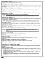
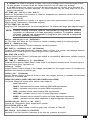
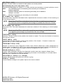
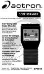
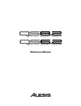
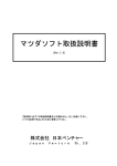
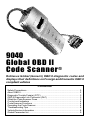
9040 Global OBD II Code Scanner ® Retrieves Global (Generic) OBD II diagnostic codes and displays their definitions on Foreign and Domestic OBD II compliant vehicles Contents Safety Precautions ................................................................................... 2 About OBD II ............................................................................................ 2 Diagnostic Trouble Code(s) (DTC) ............................................................ 3 OBD II Diagnostic Link Connector (DLC) .................................................. 3 What the Code Scanner Does .................................................................. 3 Control and Indicators .............................................................................. 4 Code Scanner Functions .......................................................................... 4 Operating the Code Scanner .................................................................... 4 Troubleshooting Tips ................................................................................ 6 Vehicle Service Information ....................................................................... 8 Global Parameter list ............................................................................... 9 Safety P r e c a u tio ns To prevent accidents that could possibly result in serious injury and/or damage to vehicles and/or test equipment, carefully follow all safety rules and test procedures: Always wear approved eye protection. Never leave vehicle unattended while Always operate the vehicle in a well- testing. ventilated area. Do not breath exhaust Always keep a fire extinguisher suitable gases they are very hazardous. for gasoline/electrical/chemical fires Always keep yourself, tools and test readily available. equipment away from moving or hot Use caution when working around the engine parts. ignition coils, ignition wires, and spark Make sure the vehicle is in Park (auto- plugs. These components produce High matic transmission) or neutral (manual Voltage when the engine is running. transmission). Set parking brake and When performing road tests, never block the drive wheels. operate the tool while driving the vehicle. Never lay tools on vehicle battery. Always have one person drive the Terminals may short together causing vehicle and the other operate the tool. harm to yourself, the tools or the battery. Always turn ignition key OFF when Never use the Code Scanner if it has connecting or disconnecting electrical components, unless otherwise been exposed to any moisture. Never smoke or have open flames near instructed. vehicle. Vapors from gasoline and Always follow vehicle manufacturers charging battery are highly flammable warnings, cautions and service procedures. and explosive. All information, illustrations and specifications contained in this manual are based on the latest information available from industry sources at the time of publication. No warranty (expressed or implied) can be made for its accuracy or completeness, nor is any responsibility assumed by the manufacturer or anyone connected with it for loss or damages suffered through reliance on any information contained in this manual or misuse of accompanying product. The manufacturer reserves the right to make changes at any time to this manual or accompanying product without obligation to notify any person or organization of such changes. About OBD II OBD II stands for On-Board Diagnostics version II. OBD II is a system that the Society of Automotive Engineers (SAE) developed to standardize automotive electronic diagnosis to minimize vehicle pollution and to allow you to use the same tool to test any make and model without special adapters. The SAE established guidelines that provide: a universal diagnostic test connector, called the data link connector (DLC), with dedicated pin assignments. a standardized location for the DLC, visible under the dash on the drivers side. a standardized list of Generic diagnostic trouble codes (DTCs) used by all manufacturers. Certain DTCs are reserved for the manufacturer. SAE publishes recommendations, not laws, but the Environmental Protection Agency (EPA) and California Air Resources Board (CARB) made many of SAEs recommendations legal requirements that car makers were required to phase in over a three-year period. Beginning in 1994, vehicles with a new engine management computer about 10% of each manufacturers fleet were supposed to comply with OBD II standards. For 1995, OBD II systems were to appear on about 40% of the new vehicles sold in the USA. Some of the 1994-1995 OBD II systems were not fully compliant, so the Government granted waivers to give manufacturers time to fine-tune their systems. Beginning in 1996, most of the new vehicles sold in the USA were fully OBD II compliant. 2 Diagnostic Trouble Code(s) (DTC) Diagnostic Trouble Codes (DTCs) consist of a five-digit alphanumeric code in the format shown below. When the On-Board Computer recognizes and identifies a problem in the computer-monitored systems, a DTC for that fault is stored in memory. These codes are intended to help you determine the root cause of a problem. As new DTCs are approved and added by the SAE, periodic updates to the software become available. Consult the store where the tool was purchased. Bx - Body Cx - Chassis Px - Powertrain Ux - Network Comm. x = 0, 1, 2 or 3 P0 1 0 1 Specific Fault Designation Vehicle Specific System Powertrain Codes P0xxx - Generic (SAE) P1xxx - Manufacturer Specific P2xxx - Generic (SAE) P30xx-P33xx - Manufacturer Specific P34xx-P39xx - Generic (SAE) Chassis Codes C0xxx - Generic (SAE) C1xxx - Manufacturer Specific C2xxx - Manufacturer Specific C3xxx - Generic (SAE) Example: P0101 - Mass or Volume Air Flow Circuit Range/Performance Problem Body Codes B0xxx - Generic (SAE) B1xxx - Manufacturer Specific B2xxx - Manufacturer Specific B3xxx - Generic (SAE) Network Communication Codes U0xxx - Generic (SAE) U1xxx - Manufacturer Specific U2xxx - Manufacturer Specific U3xxx - Generic (SAE) OBD II Diagnostic Link Connector (DLC) The Data Link Connector (DLC) allows the scan tool to communicate with the vehicle computer. OBD II defines the physical and electrical specification for the DLC. Certain pins in the connector are reserved. The DLC is also referred to as a J1962 connector, the term taken from a physical and electrical specification number assigned by SAE (Society of Automotive Engineers). The J1962 specification defines the location of the DLC in the vehicle. The DLC should be located under the dashboard on the driver side of the vehicle. If the DLC is not located under the dashboard as stated, a decal describing its location should be attached to the dashboard in the area the DLC should have been located. 1- Manufacturer Reserved 2- J1850 Bus+ 3- Manufacturer Reserved 4- Chassis Ground 5- Signal Ground 6- CAN High, J-2284 7- K Line, ISO 9141-2 & ISO/DIS14230-4 8- Manufacturer Reserved 9- Manufacturer Reserved 10- J1850 Bus 11- Manufacturer Reserved 8 9 1 16 12- Manufacturer Reserved 13- Manufacturer Reserved 14- CAN Low, J-2284 15- L Line, ISO 9141-2 & ISO/DIS14230-4 16- Battery Power What the Code Scanner Does The Code Scanner connects to the vehicle and powers-up through the DLC. Once the scanner establishes a communication link, you can then retrieve DTCs and erase data stored in the vehicle. Code Lookup provides definitions of Global (Generic) OBD II DTCs. 3 Operating the Code Scanner Control and Indicators The scan tool is designed to be as intuitive as possible. All menu and lists operate the same way. ENTER Key - selects displayed items and moves cursor in the Code Lookup function. YES/UP Arrow Key - responds yes to prompts, scrolls up and changes numbers in Code Lookup. NO/DOWN Arrow Key - responds no to prompts, scrolls down and changes numbers in Code Lookup. BACK Key - return to the previous screen or exit a function. LCD DISPLAY - A 2-line x 16-character display with contrast adjust. OBD II (J1962) Adapter Cable - provides power to the scanner and a link to the vehicle. Code Scanner Functions 1. Connect the Code Scanner to the vehicle DLC, it will not harm the vehicle. 2. The name and software ID displays momentarily. 3. Press ENTER to go to the Main Menu. 4. The display contrast can be adjusted for different viewing angles. Select Display Contrast and use the UP / DOWN arrow keys to increase and decrease the contrast. The setting will remain even when the power is disconnected. CAUTION! Avoid Cooling Fan! It May Turn On During Test. NOTE: If an Operating Error message is displayed, make sure the OBD II J1962 adapter cable is securely attached, and the ignition key is ON. Cycle the ignition key to OFF for 10 seconds, then ON. This may be required to reset the PCM. Press the BACK key to test again. If the problem still exists, refer to Troubleshooting Tips. NOTE: Do not disconnect the Code Scanner until codes have been recorded. When power is removed, Code Scanner memory is cleared. Read Codes The Read Codes function retrieves Diagnostic Trouble Codes (DTCs) from the vehicles computer modules. This function can be performed with the Key On-Engine Off (KOEO) or Key On-Engine Running (KOER). Because DTCs indicate a circuit or system failure (not component failures) they are very useful in isolating vehicle system malfunctions. There are two types of codes, Malfunction Indicator Lamp (MIL) codes and Pending codes. An icon (;) will be displayed next to DTCs that are Pending codes. MIL Codes: These codes cause the computer to illuminate the MIL when an emission related or driveability fault occurs. The MIL is also known as the service engine soon or check engine lamp. The computer illuminates the MIL when the engine is running and the DTC remains in memory until the fault is repaired. Pending Codes: These codes are also referred as continuous monitor and maturing codes. An intermittent fault causes the computer to store a code in memory. If the fault does not occur within 40 warm-up cycles, the code will be cleared from memory. If the fault occurs a specific number of times, the code matures into a DTC and the MIL turns on. 4 Turn the ignition key to the KOEO or KOER. Select Read Using the Codes and press ENTER. ® Code Scanner If there are no codes stored in vehicle memory, a System Pass message displays. If codes have been stored in vehicle memory, then the number of codes and type display (i.e. = 1 of 3 ;). Press the DOWN arrow to view the codes. The definitions for Global (Generic) DTCs display with the code number. Manufacturer-specific DTCs display the code number, and a message identifying the system and to refer to a service manual. Press the BACK key when done. NOTE: Changing any part without first isolating the circuit or system may result in the replacement of good components. Erase Codes The Erase Codes function deletes the DTCs from the vehicles memory. Perform this function only after the systems have been checked completely and DTCs have been documented. This function should be performed with KOEO - Do not START engine. An error message will usually display when performing this function with KOER. After servicing the vehicle, delete the stored DTCs and verify no codes have been reset. If DTCs return, the problem has not been corrected or other faults are present. The Erase function also erases freeze frame data, O2 sensor test data, system monitors, and on-board monitoring test results, which may be accessed by other Scan Tool type equipment. Select Erase Codes and press ENTER. Press YES to erase the codes or NO to retain the codes. If NO is chosen, a Erase Command Cancelled message appears. Once YES is selected, the function cannot be interrupted. Make sure to choose YES only if codes are to be erased permanently. A message displays stating that No Codes Remain or the number of DTCs that remain in memory. If DTCs still exist, the number will be displayed. The faults must be repaired to remove these DTCs. Press ENTER to return to the Main Menu. Press the BACK key when done. MIL Status The MIL (Malfunction Indicator Lamp) Status function displays the state of the computer module that commanded the MIL to turn on. A request is sent to the computer module(s) to state whether they are commanding the MIL to turn ON. If the MIL Status is ON and the MIL is not illuminated with the engine running, then a problem exists in the MIL circuit. Refer to Diagnostic Circuit Check in the service repair manual. NOTE: Some manufacturers will turn the MIL Off if a certain number of drive cycles occur without the same fault being detected. The DTCs related to a MIL are erased from the computers memory after 40 warm-up cycles if the same fault is not detected. Select the MIL Status function and press the ENTER key. The MIL Status displays on the top line and a scrolling message on the bottom indicating if the MIL lamp should be ON or OFF. When done, press the BACK key. I/M Monitors The I/M (Inspection and Maintenance) Monitors function displays the state of the vehicles OBD II Monitors. Monitors test the operation of emission related systems or components and detect out-of-range values. The vehicle may have to be operated under certain driving conditions to initiate a monitor. Currently, there are eleven OBD II Monitors defined and required by the U.S. Environmental Protection Agency (EPA), but not all monitors are supported by all vehicles. 5 Select I/M Monitors and press the ENTER key. Each I/M monitor and its status display Using the Code Scanner® per screen. Use the arrow keys to view them. When done, press the BACK key. A status of Ready means that the required driving conditions for that monitor have been meet and it passed. A status of Not Ready means that the required driving conditions for that monitor have not been met. A status of Not Applicable (N/A) means the vehicle does not support that monitor. View Freeze Data When an emission-related fault occurs, certain vehicle conditions are recorded by the on-board computer. This information is referred to as a Freeze Frame data. The information is a snapshot of the operating conditions at the time of a fault. This data can be overwritten by faults with a higher priority. If codes were erased, then freeze frame data may not be stored in vehicle memory. Select View Freeze Data and press ENTER. If freeze-frame data exists, then use the arrow keys to view the DTCs and parameter identification data (PIDs). If more than one computer module responds with freeze frame data, then the frame number and module display on the first line. Press the ENTER key to change modules. When done, press the BACK key. Code Lookup Code Lookup is a built-in OBD II Global (Generic) DTC database. It can be used to look up the definitions of DTCs. The DTC database does not include manufacturer specific DTC definitions. Select Code Lookup and press ENTER. All characters must be entered one character can be changed at a time. The carat (^) symbol automatically displays under the first digit. Pressing the UP/DOWN arrow keys scrolls through the digits. Once the desired digit is displayed, press the ENTER key and the ^ symbol moves under the next digit. Repeat for the remaining digits in the code. After entering the last digit, the ENTER key displays the definition. Once in the definition screen, press the UP/DOWN arrow keys to view the previous or next code definition. Press the ENTER or BACK key to return to the Code Lookup screen. Press BACK again if done. Troubleshooting Tips Perform A Visual Inspection Performing a thorough visual and hands-on underthe -hood inspection before starting any diagnostic procedure is essential. Many problems can be found this way. Visually inspect for the following: Has the vehicle been serviced recently? Sometimes things are reconnected in the wrong place, or not at all. Do not take shortcuts. Inspect hoses and wiring which may be difficult to see because of location (under air cleaner housing, alternators and similar components). Inspect the air cleaner and ductwork for defects. Check sensors and actuators for damage. 6 Inspect all vacuum hoses for: * Correct routing. Refer to vehicle service manual, or Vehicle Emission Control Information (VECI) decal located in the engine compartment. * Pinches and kinks. * Splits, cuts or breaks Inspect wiring for: * Contact with sharp edges (a common problem). * Contact with hot surfaces, such as exhaust Inspect Electrical Connectors for: * Corrosion on pins * Bent or damaged pins. * Contacts not properly seated in housing. * Bad wire crimps to terminals. * Problems with connectors are common in the engine control system. Inspect carefully. T ER P HVAC CRUISE EGR VAC REG A. M BRAKE BOOSTER FUEL PRESS REG EGR VAC REG TO TRANS MODE FRONT OF CAR 9RAC2LAB NOTE: Some connectors use a special grease on the contacts to prevent corrosion. Do not remove. If required, apply more grease to the connector (available from vehicle dealer). Code Scanner Does Not Power Up Make sure the DLC is properly connected to the vehicle connector. Verify pins are clean and fully seated in connector. The Code Scanner requires a minimum of 8 volts between pin 16 (12V) and pin 4 (Gnd) to power up. Use the flowchart to troubleshoot. 4 Scan Tool does not power up 16 Measure voltage between pins 16 and 4 Is Battery fully charged? NO Charge Battery YES Above 8V? NO Measure resistance between pin 4 and chassis ground YES Contact Technical Support Less than 5Ω? NO Repair ground circuit. Refer to Service Manual YES Open exists in power circuit. Check for a blown fuse or an open wire. Refer to Service Manual 7 Link Errors or Erroneous Data If the Code Scanner displays link errors when attempting to read, erase, or look up codes, check the following: Make sure the cable is securely connected to the DLC. Verify ignition key is ON and not in the ACCESSORIES position. Examine the DLC closely and check for cracked or recessed pins, or for any substance that could prevent a good electrical connection. Verify that the vehicle you are testing is an OBD II compliant vehicle. Just because it has the OBD II J1962 DLC does not mean the vehicle is OBD II compliant. Test for continuity between the DLC wiring and the PCM. In an extreme case there may be a broken wire. Check the vehicle for blown fuses. If the PCM fuse is blown, it cannot transmit data. NOTE: The PCM fuse may be located on the fuse block in the passenger compartment. Make sure the PCM has a good ground. If the PCM has a ground directly to the case, clean the connection and apply a conductive grease to the mating surfaces. As a last resort, the PCM may be defective. Refer to the vehicle service manual for correct procedures for testing the PCM. If the Code Scanner is not working correctly after the checks and corrections above, contact the technical support line at 1-800-228-7667 (8:00 - 6:00 EST Monday - Friday), or visit our web site at www.actron.com. Vehicle Service Information Vehicle service manuals containing additional diagnostic information are available at most auto parts stores or the local library. If unable to locate them at those locations, write the below listed publishers for availability and pricing. Please be sure to specify the make, model and year of vehicle. Vehicle Service Manuals Chilton Book Company Chilton Way Radnor, PA 19089 Haynes Publications 861 Lawrence Drive Newbury Park, CA 91320 Cordura Publications Mitchell Manuals, Inc. Post Office Box 26260 San Diego, CA 92126 Motors Auto Repair Manual Hearst Company 250 W. 55th Street New York, NY 10019 Saturn: Adistra Corporation c/o Saturn Publications 101 Union St. Post Office Box 1000 Plymouth, MI 48170 Ford Motor Company: Ford, Lincoln, & Mercury Ford Publication Department Helm Incorporated Post Office Box 07150 Detroit, MI 48207 Chrysler Corporation: Chrysler, Plymouth, & Dodge General Motors Corporation: Chrysler Motors Service Training 26001 Lawrence Avenue Center Line, MI 48015 Helm Incorporated Post Office Box 07130 Detroit, MI 48207 Suitable manuals titles are: Electronic Engine Controls Fuel Injection and Electronic Engine Controls Emissions Control Manual . . . or similar titles Buick, Cadillac, Chevrolet, GEO, GMC, Oldsmobile, & Pontiac 8 G lo b a l Pa r a m e t e r l is t All parameter identification data (PID) listed was verified on actual vehicles to guarantee accuracy. Definitions used to describe all PIDs were obtained from reliable sources and are accurate at time of printing. It is possible that some newer vehicles may contain data different from that listed in Appendix A. Always refer to vehicle service manual for manufacturer specific PIDs. Data Parameter List Format The PID list is organized in alphabetical order the same way the scan tool does. For each PID, the type of reading are provided. Remember to always refer to a vehicle service manual for detailed diagnostic procedures for troubleshooting incorrect PID readings. Types of Data Parameters INPUT: These data parameters are obtained from sensor circuit outputs. Sensor circuit outputs are inputs to vehicles PCM. For example, if Oxygen Sensor circuit was generating a 400mV signal, then scan tool would read O2S (v) 0.40. OUTPUT: These data parameters are outputs or commands that come directly from computer module(s). For example; the ignition spark advance is controlled by PCM, on most vehicles, monitoring this PID shows spark output from PCM. The scan tool would display IGN ADV(°) 10. CALCULATED: These data parameters are calculated after analyzing various inputs to the vehicles computer module(s). For example, the engine load. The PCM calculates this from sensor inputs and displays it in a percentage. PCM VALUE: Is information that is stored in the computer module(s)s memory and determined to be useful to service technician. An example of this is TROUBLE CODE value, the DTC that caused a freeze frame capture. NOTE: Several different causes can have the same parameter indication. For information on diagnostics consult vehicle service manuals. DATA PARAMETER LIST ABS FRP (0 - 655350kPA) or (0 - 95050.5PSI) Absolute Fuel Rail Pressure is the fuel pressure at the engine when reading in reference to atmosphere pressure. ABS LOAD (0 - 100%) Absolute Load Value is the normal value of air mass per intake stroke displayed as a percent. ABS LOAD (0 - 100%) Absolute Load Value is the normal value of air mass per intake stroke displayed as a percent. ABSLT TPS (0 - 100%) Absolute Throttle Position represents normal distance throttle is opened. ACC POS D,E or F (0 - 100%) Accelerator Pedal Position represents normal distance gas pedal is pressed. BARO PRESS (0 - 255kPA) or (0 - 36.9PSI) Barometric Pressure is normally received from a dedicated barometer, manifold absolute pressure sensor and other inputs during certain modes of driving. NOTE: The Baro Press may not be the same as some weather services Barometric Pressure due to being read at sea level. 9 CALC LOAD (0 - 100%) Calulated LOAD Value indicates load on engine. CAT TEMPxy (-40°C - 6513.5°C) or (-40 - 9999.9F) Catalyst Temperature Bank shall display catalyst substrate temperature for bank catalyst, if used by control module strategy for on board diagnostics monitoring, bank, sensor catalyst or temperature sensor. CLR DST (0km-65,535km) or (0- 40,722miles) Distance Since Cleared Diagnostic Codes is distance since diagnostic trouble codes were erased. CLR TIM (0 - 65535 min or 1092.25 hours) Time Since Cleared Diagnostic Code is time since diagnostic trouble codes were erased. CMD EQ RATxy (0 - 1.99) Commanded Equivalence Ratio is the ratio of the air/fuel mixture. NOTE: The CMD EQ RAT will read 1.0 while in a closed loop of fuel COOLANT (-40 - 215°C)or(°F) Engine Coolant Temperature displays engine coolant temperaturefrom engine coolant temperature or cylinder head temperature sensor. NOTE: The coolant on many diesels may use Engine Oil Temperature instead. EGR CMD (0 - 100%) Commanded Exhaust Gas Recirculation is the percentage of exhaust gas being recirculated. EGR ERR (-100 - 99.22%) Exhaust Gas Recirculation Error will show the error from changing from one condition to another. ENG RUN (0 - 65,535sec.) Time since Engine Strart is the time the engine is running. NOTE: ENG RUN stops when engine stalls or engine is turned off for any reason. ENGINE (0 - 16383.75 RPM) Engine Revolutions Per Minute is the speed engine is running. EQ RATxy O2 Sensor Equivalence Ratio is Bank x Sensor EVAP REQ (0-100%) Commanded Evaporative Purge is the positon evaporative purge control valve is open in percentage. EVAP VP (-8192PA - 8191PA) OR (-32.8878 - 32.8838 H20) Evaporative Emissions System Vapor Pressure is pressure in the fuel tank FUEL LVL (0 - 100%) Fuel Level Input is the percentage of fuel with 0% equaling tank is full and 100% when tank is empty. FUEL PRES (0 - 765kPa) or (0 - 110psi) Fuel Rail Pressure is the fuel pressure at the engine when reading in reference to atmosphere pressure. FUEL SYS (OPEN or CLSD) Fuel System Status show loop status of fuel system banks. States the fuel system can be running in: 1. OPEN: Module is operating in Open Loop control strategy. The vehicle has not yet satisfied conditions for Module to go to closed loop. 2. CLSD:PCM currently functioning in Closed loop control strategy, using O2 sensor(s) as feedback for fuel control 3. OPEN1:Open Loop control strategy is being used by the PCM due to driving conditions. Driving conditions that may cause this to happen are power enrichment and deceleration enrichment. 10 4. OPEN2:The PCM is operating in Open Loop control strategy due to detected system fault. Certain actuator or sensor faults will cause module to use an open loop strategy. 5. CLSD1:Closed Loop control is current storage being used by module, but a fault with at least one O2 sensor has been detected. The control system may be using single O2 for fuel control calculations. IAT TEMP (-40 - 215°C) or (-40 - 419°F) Intake Air Temperature is a measure of intake air temperature to determine correct air/fuel ratios and spark timing operations. IGN ADV (-64 - 63.5°) Ignition Timing Advance for cylinder is a signal of how much spark advance to add to base engine timing (expressed in crankshaft degrees). LT FL FTRM (-100 - 99.22%) Long Term Fuel Trim Bank is the fuel mixture adjustment. The mixture can range, with midpoint being 0. NOTE: Positive reading indicates module commanded a long-term rich mixture correction in response to a lean operating condition. A negative reading indicates module has commanded a long-term lean mixture in response to a rich operating condition. MAF (0 - 655.35 g/s) or (0 - 86.5lb/min) Air Flow Rate from Mass Air Flow Sensor to module indicating mass of air entering engine. MAP (0 - 255kPa) or (Hg) Intake Manifold Absolute Pressure displays manifold pressure. MIL DIST (0 - 65535km) or (0 - 40,722miles) Distance Traveled while Malfunction Indicator Lamp is Active is a counter that displays distance traveled since Check Engine or Service Engine Soon light came on. MIL STAT (ON or OFF) Monitor Status Data Trouble Code state that module is commanding Malfunction Indicator Lamp to be on if problem exists. MIL TIME (0 - 65535min) or (0 - 1092.25Hrs) Distance Since Monitor Status Data Trouble Code is the distance traveled since Check Engine or Service Engine Soon light came on. O2Sxy (0 - 1.275V) Oxygen Sensor Output Voltage is the voltage generated from the oxygen sensor to increase and decrease the amount of exhaust gas. O2Sxy (-128 - 127.996mA) Oxygen Sensor Output is used for linear or wide ratio oxygen sensors to increase and decrease the amount of exhaust gas OBD2 STAT (OBD II, OBDI, OBD, NOT OBD, EOBD and/or JOBD) On Board Diagnostic shows what vehicle was made for. Data Parameters: OBD II - Indicates vehicle meets California OBD ARB requirements OBD I - Indicates vehicle does not meet OBDII requirements. OBD - Indicates vehicle meets Federal EPA requirements. NOT OBD - Indicates vehicle is not on board diagnostic compliant. EOBD - Indicates vehicle meets European on board diagnostic requirement. JOBD - Indicates vehicle meets Japanese on board diagnostic requirment. OUTSID AIR (-40 - 215°C) or (-40 - 419°F) Outside Air Temperature gives temperature outside. PTO STATUS (OFF or ON) Power Take Off Status allows module to keep track of Power at Take-Off. REL FRP (0 - 5177.27kPa) or (750.9PSI) Realative Fuel Rail Pressure (Vacuum) is the fuel rail pressure at engine. 11 REL TPS (0 - 100%) Relative Throttle Position is relative throttle position at normal position. SECOND AIR (AIR_STAT: UPS, DNS or OFF) Commanded Secondary Air Status is on newer vehicles and actuators to control pollution control. UPS - UP STREAM module is demanding that secondary air be added at exhaust manifolds DNS- DOWN STREAM module is demanding secondary air be added at catalytic converter OFF - Module is demanding no secondary air to be added. ST FTRMxy (-100 - 99.22%) Short-term Fuel Trim Bank calculated value represents the short-term relation of fuel metering on a fuel-injected engine. NOTE: Short-term Fuel Trim calculated value that has a positive percentage is a rich fuel trim and if a negative percentage is present the fuel trim is lean. ST FLTRMx (-100 - 99.2%) Short-term Fuel Trim value represents the short-term relation of fuel metering on a fuel-injected engine. NOTE: Short-term Fuel Trim value with a positive percentage is a rich fuel trim and if a negative percentage is present the fuel trim is lean. THR POS (0 - 100%) Absolute Throttle Position is the position the throttle is located. The more the throttle is closed the less percent shown. THROT CMD (0 - 100%) Commanded Throttle Actuator Control is the position of the throttle. If throttle is closed the percent will be 0 and if wide open 100%. TRIPS SNC CLR (0 - 255) Number of warm-ups since diagnostic trouble codes cleared. Warm-up is when temperature of coolant rises to at least 22°C (40°F) from engine starting and reaching a minimum temperature of 70°C (160°F). If a disel engine the engine minimum temperature is 60°C (140°F.) TROUB CODE (00 00 - FF FF) Trouble Code Parameter will give the diagnostic trouble code that caused a freeze frame capture. This information is helpful in diagnosing the cause of a driveability. If no freeze frame data has been captured this PID will be zero. VEH SPEED (0 - 255K/h) or (0 - 158mph) Vehicle Speed shows the speed the vehicle is going. VPWR (0 - 65.535V) Control Module Voltage is the power input to the control module. ©2004 SPX Actron. All Rights Reserved. Printed in USA 0002-002-2356