1
Installation and Operation Manual
for
Speed Dome Camera
SP-607
VER:1.1
Please read the operation manual carefully
before installing and using this unit
1
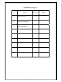
IN DOOR Packing List
No.
Name
QTY/ Unit
1
Speed Dome Camera
1
2
AC24V power supply adapter
1
3
English Operation Manual
1
2
Remark
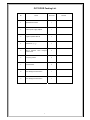
OUT DOOR Packing List
No.
Name
QTY/ Unit
1
Speed Dome Camera
1
2
AC24V power supply adapter
1
3
English Operation Manual
1
4
Wall Mount Bracket
1
5
M6×14 stainless
socket screw
6
Φ6 spring washer
4
7
Φ6 flat washer
4
8
5mm Hexagon socket wrench
1
9
3mm Hexagon socket wrench
1
steel
hexagon
3
4
Remark
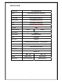
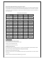
SPECIFICATION
1/4” Super HAD CCD
Image Sensor
Pixels
NTSC:768(H)x494(V)/PAL:752x582(V)
Horizontal resolution
480TVL
Video Output
1Vp-p Composite Video(75Ω)
SYNC System
Internal/External (V-Lock)
Lens
3.9mm(Wide)~85.8mm(Tele)
Zoom
230X (23X Optical,10X Digital)
48dB
S/N Ratio
Mini.Illumination
0.05Lux
0.03Lux
Picture Effect
Posi./Nega/Freeze/Cross Line/Mask Motion Detect/H/V
Reverse
White Balance
Auto(ATW Or AWB)
Auto(24dB)
Gain
Auto/Fix
AE Control
Pan
Pan Range 360 Degree,Speed
Tilt
Tilt Range 0~100 Degree, Speed 0.5~120 Degree/s
Preset
Auto Cruise
128 Preset Positions (Max)
1 Auto Cruising Tracks (Max)
Power Source
Operating Temp.
Weight
Dimensions
0.5~240 Degree/s
AC24V / 2A
0℃~+50℃
-30℃~+50℃
Approx 1.4Kg
Approx 4.5Kg
Φ133.2×178mm (H)
Φ200×336mm (H)
4
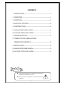
CONTENTS
1. PRECAUTIONS-------------------------------------------------------- 2
2. OPERATION------------------------------------------------------------ 4
3. ID SETTING------------------------------------------------------------- 8
4. PROTOCOL SETTING-----------------------------------------------10
5. CONSTRUCTION----------------------------------------------------- 10
5.1 INDOOR SPEED DOME CAMERA-------------------------------------------- 10
5.2OUTDOOR SPEED DOME CAMERA----------------------------------------- 11
6. TROUBLESHOTING------------------------------------------------- 12
7. CONNECTION OF RS485 BUS AND
TERMINATION RESISTER----------------------------------------- 13
8. INSTALLATION-------------------------------------------------------- 15
8.1 INDOOR SPEED DOME CAMERA-------------------------------------------- 15
8.2OUTDOOR SPEED DOME CAMERA----------------------------------------- 16
Warnings!
●
Lightning proof equipment must be installed when the speed
dome camera is installed in open area.
● Make sure the input voltage and normal rated power before
powered up.
5
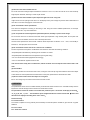
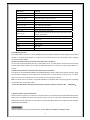
Relation Table of 24VAC Cable Diameter and Transmission distance
When the cable diameters equal, and voltage wastage rate of 24VAC is under 10%, the maximum transmission distance
is recommended. (As to AC equipments, the maximum allowed voltage wastage rate is 10%) For example: An equipment
with rating power of 80VA and installed at 10 meters away from transformer demands the maximum cable diameter of
0.8mm (square meter).
Cable Diameter (mm) Square Meter
VA(W)
Feet(m)
0.8000
1.000
1.250
2.000
10
283(86)
451(137)
716(218)
1811(511)
20
141(42)
225(68)
358(109)
905(275)
30
94(28)
150(45)
238(109)
905(275)
40
70(21)
112(34)
179(54)
452(137)
50
56(17)
90(27)
143(43)
362(110)
60
47(14)
75(22)
119(36)
301(91)
70
40(12)
64(19)
102(31)
258(78)
80
35(10)
56(17)
89(27)
226(68)
90
31(9)
50(15)
79(24)
201(61)
100
28(8)
45(13)
71(21)
181(55)
110
25(7)
41(12)
65(19)
164(49)
120
23(7)
37(11)
59(17)
150(45)
130
21(6)
34(10)
55(16)
139(42)
140
20(6)
32(9)
51(15)
129(39)
150
18(5)
30(9)
47(14)
120(36)
160
17(5)
28(8)
44(13)
113(34)
170
16(4)
26(7)
42(12)
106(32)
180
15(4)
25(7)
39(11)
100(30)
190
14(4)
23(7)
37(11)
95(28)
200
14(4)
22(6)
35(10)
90(27)
1. PRECAUTIONS
(1) Do not attempt to disassemble the camera.
To prevent electric shock, do not remove screws or covers.
There are no user-serviceable parts inside.
Ask qualified service personnel for servicing.
(2) Handle the camera with care.
Do not abuse the camera. Avoid striking, shaking, etc. The camera could be damaged by improper handling or storage.
(3) Do not use strong or abrasive detergents when cleaning the camera body.
Use a dry cloth to clean the camera when it is dirty.
When the dirt is hard to remove, use a mild detergent and wipe gently. Care should be taken not to scratch the dome
when wiping it.
Afterwards, wipe off the remained part of the detergent in it with a dry cloth.
6
(4) Never face the camera towards the sun.
Do not aim the camera at bright objects. Whether the camera is in use or not, never aim it at the sun or other extremely
bright objects. Otherwise, blooming or smear maybe caused.
(5) Never face the camera towards a place exposed to light sources for a long time.
If light sources such as spot light cause burn-in on the display screen, part of image may discolor due to deterioration of
color filter in CCD when changing aim of the camera etc.
(6) Do not install this camera upside down.
This camera is designed for mounting on the ceiling or wall. Using this camera installed upside down, for example,
mounted on the floor, may cause malfunction.
(7) Do not operate the camera beyond the specified temperature, humidity or power source ratings.
Do not use the camera in an extreme environment where high temperature or high humidity exists. Do not place near
heat sources such as radiators, stoves or other units that produce heat.
Use the Indoor Speed Dome camera under conditions where temperature is between -10°C - +40°C, and humidity is
below 90 %. The input power source is AC24V.
(8) Do not install the camera near the air out-let of an air conditioner.
The lens may become cloudy due to condensation if the camera is used under the following conditions.
• Rapid temperature fluctuations by switching the air conditioner on and off
• Rapid temperature fluctuations due to frequent door opening and closing
• Use in an environment where eyeglasses become foggy
• Use in a room filled with cigarette smoke or dust.
If the lens becomes cloudy due to condensation, remove the dome cover and wipe all moist surfaces with a soft
cloth.
(9) Consumables
Parts having contacts such as the lens-drive motors, cooling fan motor and slip-rings built inside the camera are subject
to wear with time. About replacement and maintenance of such parts, please ask the nearest service center.
(10) Do not aim the camera at the same object for a long time.
Burn-in of an image may be caused on the fluorescent screen of CRT.
2.OPERATION
The speed dome camera can be controlled remotely horizontal and vertical movement. It is controlled remotely from the
keyboard or controller through a serial connection to the RS-485 connector.
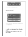
The speed dome camera will conduct a self-check after powered up and the monitor will display as following:
“P:P_D,ID:001,V:2a1”. The information will be disappeared after the self-check is finished.(Protocol and
ID code will be displayed according to the users’ choice)
Normal Function:
2.1 Pan/Tilt Function
The camera is capable of moving vertically and horizontally. The Pan/Tilt speed is variable for given amount of joystick
deflection.
2.2 Lens Function
2.2.1 Zoom Lens Function
7
Transform the view angle of the camera(zoom in / zoom out),press[TELE] or [WIDE]。
2.2.2 Focus Function
In some special circumstance, users need conduct focus manual, he can press [NEAR] or [FAR] to transform the focus
and press [CALL] + 59 + [ENTER] or operate the joystick to recover the auto mode.
2.2.3 Iris Function
In normal circumstance, iris is in auto mode. If users need to change the iris level, they can press [OPEN] or [CLOSE] to
adjust. Press [CALL] + 60 + [ENTER] or operate the joystick, iris will be auto.
2.3 Preset Function
The speed dome camera is capable of going to 128 preset positions. Each is with its own P/T/Z and focus. (Preset
positions 50-66 are reserved for auxiliary functions.) When preset a camera position, the P/T/Z and focus will be
memorized for that position.
2.3.1 To set a preset position
[PRESET] + nnn + [ENTER], the LCD displays: SET PRESET :nnn
nnn→the number of preset position: 1~128
2.3.2 To call a preset position
When camera positions have been preset, you can enter a memorized camera position number.
[CALL] + nnn + [ENTER], the LCD displays: CALL PRESET:nnn
nnn→the number of preset position: 1~128
2.3.3 To delete a preset position: (Only be effective to Protocol COP-2. Some special keyboards no function)
[DELPRESET] + nnn + [ENTER], the LCD displays:CLEAR
PRESET :nnn
nnn→the number of preset position which will be deleted
2.4 Auxiliary Functions List
Operation
Function
F1 + 0 + Off
Camera reset
F1 + 1 + On
Backlight compensation ON
F1 + 1 + Off
Backlight compensation OFF
F1 + 2 + On
LOW illumination ON
F1 + 2 + Off
Auto LOW illumination
F1 + 3 + On
Menu/Display ON
F1 + 3 + Off
Menu/Display OFF
F1 + 4 + On
Digital zoom ON
F1 + 4 + Off
Digital zoom OFF
F1 + 5 + On
Keyboard LCD display Back Light ON
F1 + 5 + Off
Keyboard LCD display Back Light OFF
F1 + 6 + On
Auto FOCUS
F1 + 6+ Off
Manual FOCUS
F1 + 7 + On
Auto IRIS
F1 + 7+ Off
Manual IRIS
F1 + 8 + On
Auto White balance (AWB)
F1 + 10 + On
White balance Auto follow model (ATW)
F1 + 11 + On
Color picture
F1 + 11+ Off
B/W picture
8
Operation
Call + 33 + Enter
Call + 51+ Enter
Preset + 51+ Enter
Call + 52+ Enter
Preset + 52+ Enter
Call + 53 + Enter
Preset + 53+ Enter
Preset + 54+ Enter
Call + 55+ Enter
Preset + 55+ Enter
Call + 58+ Enter
Preset + 58+ Enter
Call + 59+ Enter
Preset + 59+ Enter
Call + 60+ Enter
Preset + 60+ Enter
Pan 180°
Scan start
Set the start position of scan
Scan stop
Set the end position of scan
Auto cruise from No.1 preset position to NO.16 preset position
Do self-test
Camera reset
Backlight compensation ON
Backlight compensation OFF
Digital zoom ON
Digital zoom OFF
Auto FOCUS
Manual FOCUS
Auto IRIS
Manual IRIS
Call + 61+ Enter
Auto White balance (AWB)
Preset + 61+ Enter
White balance Auto follow model (ATW)
Image Mirror ON
Image Mirror OFF
Show of operation
No show of operation
Color video
B/W video
Running SEQ after five minutes OFF
Running SEQ after five minutes ON
Camera menu ON
Camera menu ON
Call + 63+ Enter
Preset + 63+ Enter
Call + 64+ Enter
Preset + 64+ Enter
Call + 67+ Enter
Preset + 67+ Enter
Call + 90+ Enter
Preset + 90+ Enter
Call + 95+ Enter
Preset + 95+ Enter
Function
9
Operation
Function
Call + n + Enter
To call the number N preset position
Preset + n + Enter
To set the number N preset position
Preset + n + Off
Delete the number N preset position
Cam + n + Enter
Set the dome address “n”
Shot + n + Enter
N=1:Auto the cruise track
Shot + n + Off
N=1:Stop the cruise tracks
Auto + On
Set the start position of auto pan
Auto + Off
Set the end position of auto pan
Auto + Enter
The camera will move from the auto pan start position to the
auto pan end position
Wide
ZOOM wide
Tele
ZOOM tele
Far
FOCUS far
Near
FOCUS near
Open
IRIS open
Close
IRIS close
(1) Title Display Function
No.64 preset position can turn on or turn off the display function (including self-check information display) of some certain
cameras. If the No.64 preset position is a normal one, the camera does not have the display function (including
self-check information display).
(2) When camera performs cruise function, the tolerant state is as follows:
To scan point by point automatically from No. 1 preset position to No. 16 preset position. The cruise will not scan those
positions where certain positions are un-preset or deleted after preset, and resort time for each preset position is 3
seconds;
(3) When camera performs scan function, the tolerant state is as follows:
The camera will scan automatically between two designated positions, namely “starting point” (left) and “end point” (right).
The resort time at “starting point” and “end point” is 3 seconds; states of dome camera are shown below. The dome
camera will stop scan and implement new action when receiving qualified command.
Note: The dome camera may result in accumulative deviation in parameters after serving a long period. The starting
point and end point of scan shall be reset.
(4) The item marked with * means the camera have this function, otherwise it will show “NO
FUNCTION”。
5. Special Function—Power-off Protection
When the camera is under scan or cruise track, and power off occurs, the camera will save the state before the power-off.
When power is resupplied, the camera will continue to perform the scan or cruise track automatically under the same
state before power-off. Should scan or cruise track are not performed before power-off, the camera will stop at the first
preset position automatically.
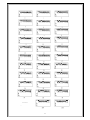
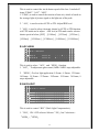
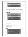
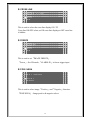
3.ID SETTING
ID of this speed dome can be set by the switch with 10 codes. Below is the detail of setting ID code:
10
¯¯¯¯¯¯¯¯¯¯¯¯
¯
11
Note:Control cables can connect multiple speed dome cameras in parallel provided that No. 10 ID code of the farthest
camera is set to “ON”. The operation is required when the control distance is quite far.
The No. 10 ID code should be set to “ON” for the last camera connected to the daisy chain.
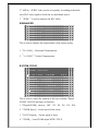
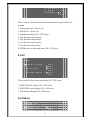
4.PROTOCOL SETTING
Protocol of this speed dome can be set by the switch with 3 protocol codes. Below is the detail of setting protocol
code:
Note:All setting must be operated after power off.
Power on until it is completed.!
Protocol
setting
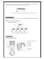
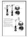
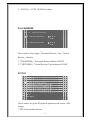
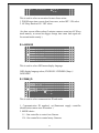
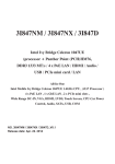
5. CONSTRUCTION
5.1 Indoor Speed Dome Camera
Dome Camera mounting base
AC24VInput
Video Output
RS485data
Dome Housing
Camera
12
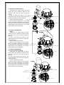
◆ CONNECTIONS
PRECAUTIONS
※
The following connections should be made by qualified service personnel or system installers in
accordance with all local codes.
Red L
Black N
AC24V
AC24V
Video Output
Orange RS485+
RS485 Signal
Yellow RS485-
Note: When powered up, the camera performs a self-check for about 2 minutes (including one panning, tilting, zooming
and focusing operation). During the period, control operations are not executed.
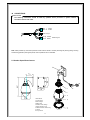
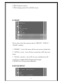
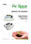
5.2 Outdoor Speed Dome Camera
1 Wall Mount
3 AC24V Input
4 Video Output
5 RS485 data
6 Outdoor Dome Flange
7 Safety Hanging-Lock
8 Aluminum Die Cast Housing
9 Camera
10 Acylic dome
13
◆ CONNECTIONS
PRECAUTIONS
※
The following connections should be made by qualified service personnel or system installers in
accordance with all local codes.
Red L
Black N
AC24V
AC24V
Video Output
Orange RS485+
RS485 Signal
Yellow RS485-
Note: When powered up, the camera performs a self-check for about 2 minutes (including one panning, tilting, zooming
and focusing operation). During the period, control operations are not executed.
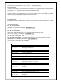
6. TROUBLESHOTING
Trouble
No action, no
powered up
video
after
Self-check isn’t normal, but
image is normal and obstacle
found in operation.
Self-check is normal but no
image
Self-check is normal but it is
uncontrollable
Possible Causes
Power supply is not well connected
Engineering cable failure
The power supply is not well connected
Machine failure
The camera is declining
Voltage is low
The contact of video cables is incorrect
The contact of video cables is loose
Camera is damaged
The connection of control signal is incorrect
Camera number is not set correctly.
Protocol setting is incorrect
RS485 cable A+&B- connection is not correct
RS485 cable is too long
RS485 signal network is star configuration
Instable image
The camera is uncontrollable
and running unceasingly
Abnormal video
The contact of video cables is loose
Voltage is low
Dropout occurs due to low voltage
Self-check is abnormal
The operation of mainframe is not correct
RS485 bus line isn’t equipped with matched
resistance, or the resistance is not matched.
Extremely bright video
14
Solution
Replace
Eliminate
Correct
Repair
Put straight
Change power and place it near the
camera
The distance between AC24V power
supply to dome camera must be less
50 meters
Correct
Eliminate
Replace
Correct
Reinstall
Correct
Correct
The maximum cable for RS485
communication is 1.2km
Star distributor is used at junction of
connection
Eliminate
Replace
Check ID address settings
Power up again
Power up again
Correct
No termination or high resistance
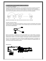
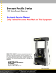
7. CONNECTION OF RS485 BUS AND TERMINATION RESISTOR
(1) Characteristics of RS485 Bus
As specified by RS485 standards. RS485 Bus is of half duplexed data transmission cables with characteristic
impedance as 12. The maximum load is 32 unit loads (including main controller and controlled equipment.)
(2) The RS485standarda require a daisy-chain connection between the equipment. There must be termination
resistor with 120 ohms impedance at both ends of the connection (refer to the following FIGURE)
When No. 10 bit of the Dip is set to “ON”, the 120 ohms termination resistor is connected.
(3) Problem in Practical Connection
In some circumstances user adopts a star configuration in practical connection. The termination resistors must be
connected to the two equipments (No. 6 and No. 10) that are farthest away from each other. But the connection
does not meet the RS485 standards.
120Ω
1#
Control
120Ω
120Ω
6#
12#
When the cable distance of equipments are far away, some problems, such as signal reflection, anti-jamming
ability decrease are easily occur and result in the reliability decline of control signal. The resulted phenomena
represent that the camera is out of control completely or interruptedly or operates automatically and fails to
stop, etc. In such circumstances the factory recommends the RS485 Signal Distributor. The distributor can
change the star configuration connection to the mode of connection stipulated in the RS485 standards. The
mew connection achieves reliable data transmission.
RS485 Distributor
RS485 Distributor
15
Each connection can connect 32 terminations, and practical connections must be considered.
8. INSTALLATION
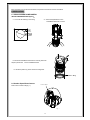
8.1 INDOOR SPEED DOME CAMERA
INDOOR EMBEDDED MOUNT(Option):
(2)Mount the Speed Dome on the
embedded bracket with 4 screws.
Max80
(1)Cut a hole as following in the ceiling.
(3)Mount the embedded bracket into the mounting holes and
adjust 3 presser feet. Fix the embedded bracket.
(4)Mount the plastic ring to the camera mounting base.
Pl ast i c Ri ng
8.2 Outdoor Speed Dome Camera
Note: Protocol and ID code( fig. 1)
Protocol and ID
Fig. 1
16
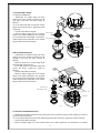
A. OUTDOOR WALL MOUNT
A1 WITHOUT POWER BOX
① Disassemble the outdoor flange and dome
housing with wrench. Decide the protocol and ID
code (fig.1), and mount the dome housing as
following.
2 Fix the wall bracket and connect it with outdoor
○
flange with screws and wrench. Tighten the screws
as following.
③ Connect all the cables as required.
④ Mount the Safety Hanging-Lock of the outdoor Outdoor Flange
flange on the outdoor speed dome. Aim the guide
pin of mounting base at the longest curved chute of Safety Hanging-Lock
outdoor flange. Fix the speed dome on the outdoor
flange. Tighten the screw as following.
Longest Curved Chute
Guide Pin
A2WITH POWER BOX(Option)
① Disassemble the Outdoor Flange and dome
housing with wrench. Decide the protocol and ID
code(fig.1) and mount the dome housing as
following.
② Mount the power box on a solid ceiling. Mount
the wall bracket on the power box.
③ Fix the wall bracket to the outdoor flange with
screws and wrench. Tighten the screws as
following.
④ Connect all the cables as required.
⑤ Mount the Safety Hanging-Lock of the outdoor
flange on the outdoor speed dome. Aim the guide
pin of mounting base at the longest curved chute of
outdoor flange. Fix the speed dome on the outdoor
flange. Tighten the screw as following.
Fig. 2
Outdoor Flange
Safety Hanging-Lock
Longest Curved Chute
Guide Pin
Fig. 2
B. OUTDOOR CEILING MOUNT(Option)
① Disassemble the Outdoor Flange and dome housing with wrench. Decide the protocol and ID code(fig.1), and mount
the dome housing as following.
2 Fix the ceiling bracket and connect it with outdoor flange with screws and wrench. Tighten the screws as following.
○
③ Connect all the cables as required.
④ Mount the Safety Hanging- Lock of the outdoor flange on the outdoor speed dome. Aim the guide pin of mounting
17
base at the longest curved chute of outdoor flange. Fix the speed dome on the outdoor flange. Tighten the screw as
following.
Outdoor Flange
Longest Curved Chute
Safety Hanging-Lock
Outdoor Flange
Guide Pin
Safety Hanging-Lock
Fig. 2
Fig. 2
C. OUTDOOR WALL MOUNT(Option)
① Disassemble the outdoor flange and dome
housing with wrench. Decide the protocol and ID
code (fig.1), and mount the dome housing as
following.
2 Fix the wall bracket and connect it with outdoor
○
flange with screws and wrench. Tighten the screws
as following.
③ Connect all the cables as required.
④ Mount the Safety Hanging-Lock of the outdoor
flange on the outdoor speed dome. Aim the guide
pin of mounting base at the longest curved chute of
outdoor flange. Fix the speed dome on the outdoor
Outdoor Flange
flange. Tighten the screw as following.
Longest Curved Chute
Safety Hanging-Lock
Guide Pin
Fig. 2
18
D. OUTDOOR POLE MOUNT(Option)
① Disassemble the outdoor flange and dome
housing with wrench. Decide the protocol and ID
code(fig.1), and mount the dome housing as
following.
② Fix the pole bracket and mount it to the wall
Outdoor Flange
bracket with screws. Mount the outdoor flange to the
wall bracket. Tighten the screws as following.
Safety Hanging-Lock
③ Connect all the cables as required.
④ Mount the Safety Hanging-Lock of the outdoor
flange on the outdoor speed dome. Aim the guide pin
of mounting base at the longest curved chute of the
outdoor flange. Fix the speed dome on the outdoor
flange. Tighten the screw as following.
Longest Curved Chute
Guide Pin
Fig. 2
E. OUTDOOR CORNER MOUNT
(Option)
① Disassemble the outdoor flange and dome
housing with wrench. Decide the protocol and ID
code (fig.1), and mount the dome housing as
following.
2 Fix the corner bracket and connect it with
○
outdoor flange with screws and wrench. Tighten the
screws as following.
③ Connect all the cables as required.
④ Mount the Safety Hanging-Lock of the outdoor
flange on the outdoor speed dome. Aim the guide
Outdoor Flange
pin of mounting base at the longest curved chute of
Safety Hanging-Lock
outdoor flange. Fix the speed dome on the outdoor
flange. Tighten the screw as following.
F. OUTDOOR CORNER MOUNT
D1WITHOUT POWER BOX (Option)
① Disassemble the outdoor flange and dome
housing with wrench. Decide the protocol and ID
code (fig.1), and mount the dome housing as
following.
2 Fix the corner bracket and connect it with
○
outdoor flange with screws and wrench. Tighten the
screws as following.
③ Connect all the cables as required.
④ Mount the Safety Hanging-Lock of the outdoor
flange on the outdoor speed dome. Aim the guide
pin of mounting base at the longest curved chute of
outdoor flange. Fix the speed dome on the outdoor
flange. Tighten the screw as following.
Longest Curved Chute
Guide Pin
Fig. 2
Longest Curved Chute
Outdoor Flange
Safety Hanging-Lock
Fig. 2
Guide Pin
19
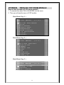
APPENDIX
: MENU OF COP ZOOM MODULE
How to enter the menu of COP zoom module?
1. To execute the order CALL+95+ENTER into the menu.
2. Then you will see the menu of COP module
Main Menu ( Page 1. )
S E T U P
Î W
I
A
B
E
Z
H
T
P
H
R
G
A
N
O
/
I
R
I
I
C
C
H
O
V
T
E
T
S
・
K
A
M
M E N U
E
( 1
/ 3 )
B A L A N C E
S
L
N
・
R
L E
S E
E
I
C
F
E
N
G
E
O
V
S
H T
R
C U S
E R S E
T
Main Menu ( Page 2. )
S E T U P
Î M
P
G
P
M
O
Z
L
C
O
O
A
O
A
S
O
A
O
T
S
M
W
S
D
O
N
M
I
I
M
E
K
M E N U
( 2
/ 3 )
O N
D E T E C T
T I O N
A
R
O N
M + A F
G U A G E
M ・ I D
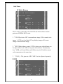
Main Menu ( Page 3. )
S E T U P
M E N U
(
ÎC R O S S
L I N E
F R E E Z E
P O S I / N E G A
20
3 /
3 )
Sub Menu
White Balance
W H I T E
B A L A N C E
Î C O L O R
O
O
Î A
E
F F
N
U T O
X T
W B
Î A T W
A W B
R R -
-
- ■ - ■ -
- B
- B
G A I N
Î R - Y
B - Y
-
-
- ■ - ■ -
-
-
-
This is used to control the color ON/OFF and white balance and the
gain rate of RED & BLUE color.
1.「COLOR」selector:OFF is monochrome image,ON is normal color
image,AUTO is at low light AGC up, display image will be auto
change to monochrome image.
2. 「WB」White balance control:ATW is Auto trace white balance,can
be adjust offset level. AWB is One push white balance. Push [menu]
key「AWB」will start flicker, until flicker stop it will lock the current
color temperature at the same time.
:The gain rate of R-Y & B-Y can be adjusted separately.
3. 「GAIN」
IRIS
I R I S
Î P E A K
Î O F F
O N
A ■ -
-
-
-
- P
A L C
Î A U T O
F I X
-
-
- ■ - ■ -
-
-
A E S
A U T O
Î F I X
-
- - ■ O F F
-
-
21
This is used to control the iris & shutter speed of the lens. It included 3
items “PEAK”, “ALC”, “AES”.
1.「PEAK」is used to control the reaction of auto iris, which is based on
the average light of picture signal or the light rate of the peak.
2.「ALC」is used to select AUTO or FIX. Adjust IRIS level.
3.「AES」is used to select electronic shutter be AUTO or FIX function,
at AUTO mode can be adjust AES level,at FIX mode can be selector
shutter speed at below, [OFF],[1/100sec],[1/120sec],[1/250sec],
[1/500sec],[1/1000sec],[1/2000sec],[1/4000sec],[1/10000sec]
AGC・SENS
A G C ▪ S E N S
Î A G C
S E N S
A U T O
A U T O
- ■ -
- ■ - - -
-
-
This is used to select「AGC」and「SENS」function.
:To adjust auto gain control, 0dBb~24dB 9 steps adjustable.
1.「AGC」
2. 「SENS」
:For low light application: 0 Frame,6 Frame,12 Frame,
16 Frame,18 Frame,22 Frame,24 Frame,30 Frame,36 Frame, 9
steps adjustable.
BACKLIGHT
B A C K L I G H T
Î O F F
O N
Î A R E A
S E N S
L O W -
-
-
- ■ -
-
- H I
This is used to control “BLC” (Back Light Compensation),
1.「BLC」ON / OFF selector. Selector「ON」has 2 sub-items:
「AREA」,
「SENS」.
22
2.「AREA」: 48 BLC zones can be set separatly. According to the mask
area (BLC zone) signal to decide the iris and shutter speed.
:Is used to enhance the BLC effect.
3.「SENS」
ENHANCER
E N H A N C E R
H ▪ G A I N
-
-
-
-
-
- ■ -
-
-
V ▪ G A I N
-
-
-
-
-
- ■ -
-
-
This is used to enhance the compensation of the picture quality.
1.「H • GAIN」:Horizontal Compensation
2.「V • GAIN」:Vertical Compensation
ZOOM・FOCUS
Z O O M ▪ F O C U S
Î D I G I T A L
Z O O M
F O C U S
Z O O M
S P E E D
S P E E D
Z O O M
F O C U S
Î M A N U A L
A U T O
O F F
-
-
- ■ - ■ -
W I D E
I N F
-
T E L E
N E A R
This is used to control the montion of the lens, included “Digital
ZOOM” ON/OFF and times set function.
1.「Digital ZOOM」selector:OFF、X2、X4、X6、X8、X10.
2.「ZOOM Speed」:Set the speed of the zoom.
:Set the speed of focus.
3.「FOCUS Speed」
:Lens ZOOM adjust WIDE / TELE
4.「ZOOM」
23
:AUTO / MANUAL setting
5.「FOCUS」
H/V REVERSE
H / V
R E V E R S E
Î H ▪ R E V E R S E
Î O F F
O N
V ▪ R E V E R S E
Î O F F
O N
This is used to select image「Horizontal Reverse」and「Vertical
Reverse」function.
1.「H.REVERSE」:Horizontal Reverse (Mirror) ON/OFF
2.「V.REVERSE」:Vertical Reverse (Up-side down) ON/OFF
TITLE
T I T L E
Î 0
A
N
a
n
□
U
D
1
B
O
b
o
:
P
O
2
C
P
c
p
;
3
D
Q
d
q
'
4
E
R
e
r
"
5
F
S
f
s
.
6
G
T
g
t
,
7
H
U
h
u
<
8
I
V
i
v
>
9
J
W
j
w
(
K
X
k
x
)
L
Y
l
y
[
M
Z
m
z
] {
} ┌ ┘ ─ *
/
W N
This is used to set up the ID figures & position on the screen. (Title
setting)
1.TITLE start position selector.
24
2.TITLE Character selector.
3.TITLE display position UP or DOWN selector.
PRESET
P R E S E T
Î O F F
O N
I N I
O F
Î O N
P H A
Î O F
O N
─
T I A L
F
S E
F
-
-
-
-
-
- ■ -
-
-
-
+
This is used to select the camera go back to “PRESET”, “INITIAL”,
“PHASE” condition
1.「PRESET」:Set to ON camera will be reset and set to default data.
2.「INITIAL」select:Set to ON lens is action,Set to OFF lens is not
action.
3.「PHASE」adj select:Set to OFF ext-sync is disable,Set to ON
ext-VD sync is enable,(EXT-VD signal must be input)
4. PHASE set to ON sync-phase adjustment.
MOTION DETECT
M O T I O N
D E T E C T
Î O F F
O N
T I M E
1 0 S E C
25
Î 3 0 S E C
6 0 S E C
S E N S
L O W
-
-
- ■ -
-
-
H I
This is used to select the montion detcet function.
1. Motion detect ON / OFF select.
2. Motion detects area select.
3. Motion detects output time select.
4. Motion detect sensitive adjust.
POSITION
P O S I T I O N
A L A R M
F R E E Z E
P O S I
( N O
Z O
F O
Z O
F O
T
=
O
C
O
C
N O = 0
( O F F
O N
I O N
1
M
S P E E D
U S
S P E E D
M
W I D E
U S
I N F
-
-
T
N
■
■
E
E
L
A
E
R
This is used to set「ALARM-IN」function,either「ALARM POSITION」
or「IMAGE FREEZE」.
:Set alarm position(1~64),if set to (0) alarm position
1.「ALARM NO.」
is not enable.
2.「Freeze」:Set ON mode,「ALARM-IN」is freeze trigger input.
3.「POSITION」:The alarm position have 64 steps (position) can be
programed.
By this program,the zoom & focus may go to the exactly position
where is programed.
26
GAMMA
G A M M A
ÎT Y P E 1
T Y P E 2
This is used to select the camera gamma correction.
「GAMMA」select:TYPE-A gamma is 0.45, TYPE-B gamma is 1.0
POWER ON
P O W E R
O N
Î B L U E
O F F
Î O N
B A C K
P O S I T I O N
Î O F F
O N
N O = 1
This is used to select the camera power on state.
1.「BLUE BACK」:Set to OFF camaer power on initial is normal
display, Set to ON camaer power on initial is display blue back.
2.「POSITION OFF」:Camera power on lens position is current
position.
3.「POSITION ON」:Camera power on lens position is go to the
designation position(1~64).
MASK
M A S K
Î P O S I T I
M A S K
N
Î O
O
O N
N O = 1
O = 1
F F
N
Î H - S T A R T = 2 0
H - E N D
= 2 0
27
V - S T A R T = 2
V - E N D
= 2
C O N N E C T Î O
O
0
0
F F
N
This is used to select mask area size and position for each setable lens
position.
1. Lens position no. select(1~64)
2. MASK NO. select(1~4)
3. MASK area display ON / OFF select.
4. Hor. direction start position.
5. Hor. direction end position.
6. Ver. direction start position.
7. Ver. direction end position.
8.ZOOM action to link mask area, ON / OFF select.
OSD
O S D
Î P O S I T I O N
O
Î O
Î O
O
Î O
O
M O T I O N
Z O O M ▪ M A G
F F
N
F F
N
F F
N
This is used to select on screen display ON / OFF select.
1. POSITION NO. display ON / OFF select.
2. MONTION action display ON / OFF select.
3. ZOOM times display ON / OFF select.
ZOOM+AF
Z O O M + A F
Î Z O O M + A F
Î O F F
O N
28
A F
S L E E P
Î O F F
O N
This is used to select an occasion for auto focus action.
1. ZOOM stops time execute lens focus once, action OFF / ON select.
2. AF Sleep function ON / OFF select.
(As show screen stillness about 5 minutes cameras come into AF Sleep
mode namely, as screen has bigger change time come back again act
for normal mode namely.)
LANGUGE
L A N G U A G E
Î E N G L I S H
C H I N E S E
J A P A N E S E
This is used to select OSD manu display language.
OSD display language select, ENGLISH / CHINESE (Simp.) /
JAPANESE
COMM・ID
C O M M ▪
I D
Î C O M M ▪
M O D E
I D = 1
Î 1 : 1
1 : N
This is used to select communcation ID and mode.
1. Communication ID number's set.(Enactment supply controller
identification camera uses ID number.)
2. MODE choice
1:1 : One controller to control one Camera.
1:N : One controller to control many Cameras.
29
CROSS LINE
C R O S S
L I N E
Î O F F
O N
This is used to select the cross line display ON / FF.
Cross line ON/OFF select,set ON cross line display,set OFF cross line
is hidden.
FREEZE
F R E E Z E
Î O F F
O N
This is used to set「IMAGE FREEZE」.
「Freeze」:Set ON mode,「ALARM-IN」is freeze trigger input.
POSI / NEGA
P O S I
/ N E G A
Î P O S I
N E G A
This is used to select image「Positive」and「Negative」function.
「POSI/NEGA」:Image positive & negative select.
30
31