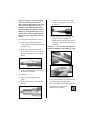
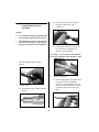
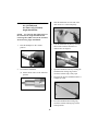
1
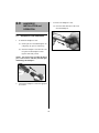
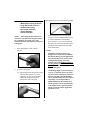
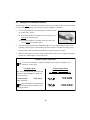
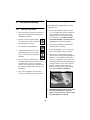
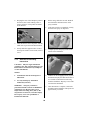
Hall® MicroPower™ High Speed Drill
Instruction Manual
(6020-026 / 6021-026)
Proprietary Information
This manual contains information deemed proprietary to Linvatec Corporation. The
information contained herein, including all of the designs and related materials, is the sole
property of ConMed Linvatec and/or its licensors. ConMed Linvatec and/or its licensors
reserve all patent, copyright and other proprietary rights to this document, including all
design, manufacturing methodology and reproduction.
This document, and any related materials, is confidential and is protected by copyright laws
and shall not be duplicated, transmitted, transcribed, stored in a retrieval system, or
translated into any human or computer language in any form or by any means, electronic,
mechanical, magnetic, manual or otherwise, or disclosed to third parties, in whole or in part,
without the prior express written consent of ConMed Linvatec.
ConMed Linvatec reserves the right to revise this publication and to make changes from time
to time in the contents hereof without obligation to notify any person of such revision or
changes, unless otherwise required by law.
Linvatec, Hall, Advantage, PowerPro, E9000, Surgairtome Two, Micro 100, Ultrapower,
MicroPower, and SmartGuard are trademarks or registered trademarks of Linvatec
Corporation.
© ConMed Linvatec Corporation 2006. All Rights Reserved. Printed in USA
Record the Model and Serial Numbers of the handpiece(s), and date received. Retain for
future reference.
Handpiece Model No.
Handpiece Model No.
Handpiece Model No.
Handpiece Model No.
Handpiece Model No.
Handpiece Model No.
Handpiece Model No.
Handpiece Model No.
Serial No
Serial No
Serial No
Serial No
Serial No
Serial No
Serial No
Serial No
Date
Date
Date
Date
Date
Date
Date
Date
Page
Table of Contents
1.0
2.0
INTRODUCTION
1.1
Intended Use . . . . . . . . . . . . . . . . . . . . . . . . . . . . . . . . . . . . . . . . . . . . . . . . . . . . . . . . . 1
1.2
Warnings and Cautions. . . . . . . . . . . . . . . . . . . . . . . . . . . . . . . . . . . . . . . . . . . . . . . . . 1
1.2.1
Warnings . . . . . . . . . . . . . . . . . . . . . . . . . . . . . . . . . . . . . . . . . . . . . . . . . . . . . 1
1.2.2
Cautions . . . . . . . . . . . . . . . . . . . . . . . . . . . . . . . . . . . . . . . . . . . . . . . . . . . . . . 2
1.3
Symbol Definitions . . . . . . . . . . . . . . . . . . . . . . . . . . . . . . . . . . . . . . . . . . . . . . . . . . . . 3
1.4
MicroPower High Speed Drill . . . . . . . . . . . . . . . . . . . . . . . . . . . . . . . . . . . . . . . . . . . 4
1.5
Irrigation Tubing Set (E9418) for use with the MicroPower High Speed Drill . . . . . . 5
HANDPIECE INSTALLATION and OPERATION
2.1
Handpiece Cord Installation . . . . . . . . . . . . . . . . . . . . . . . . . . . . . . . . . . . . . . . . . . . . . 6
2.2
Hall Bur Guard Assembly Instructions. . . . . . . . . . . . . . . . . . . . . . . . . . . . . . . . . . . . . 7
2.3
2.4
2.5
2.2.1
Assembly Instructions for the Medium Bur Guard (1375-012),
Long Bur Guard (1375-011), Cloward Extra-Long Bur Guard (1375-023),
Tissue Retractor Guard (1387-022) . . . . . . . . . . . . . . . . . . . . . . . . . . . . . . . . . 8
2.2.2
Assembly Instructions for the Laminectomy Bur Guard (1375-020) . . . . . . 10
2.2.3
Assembly Instructions for the 20° (1375-032) and 20° Extra Long
(1375-033) Angle Attachments . . . . . . . . . . . . . . . . . . . . . . . . . . . . . . . . . . . 11
2.2.4
Assembly Instructions for the 70° Contra-Angle with Surgical
Head (1375-034), 70° Contra-Angle with Dental Head (1375-035),
90° Angle (1375-036) Attachments. . . . . . . . . . . . . . . . . . . . . . . . . . . . . . . . 12
Handpiece Operation . . . . . . . . . . . . . . . . . . . . . . . . . . . . . . . . . . . . . . . . . . . . . . . . . 13
2.3.1
Tubing Set Attachment (E9418) for the MicroPower High Speed Drill . . . . 13
2.3.2
Preoperative Functional Test for the MicroPower High Speed Drill . . . . . . 14
2.3.3
High Speed Drill Attachments and Accessories . . . . . . . . . . . . . . . . . . . . . . 15
2.3.4
Removing the Detachable Handpiece Activation Lever . . . . . . . . . . . . . . . . 16
Footswitch Operation . . . . . . . . . . . . . . . . . . . . . . . . . . . . . . . . . . . . . . . . . . . . . . . . . 17
2.4.1
Operation of the 2-Pedal Footswitch (5020-053) . . . . . . . . . . . . . . . . . . . . . 17
2.4.2
Operation of the 3-Pedal Footswitch (C9863) . . . . . . . . . . . . . . . . . . . . . . . . 17
Handpiece Cord Button Operation . . . . . . . . . . . . . . . . . . . . . . . . . . . . . . . . . . . . . . . 18
i
Page
Table of Contents
3.0
MAINTENANCE
3.1
Cleaning and Sterilizing . . . . . . . . . . . . . . . . . . . . . . . . . . . . . . . . . . . . . . . . . . . . . . . 21
3.1.1
Cleaning Precautions . . . . . . . . . . . . . . . . . . . . . . . . . . . . . . . . . . . . . . . . . . . 21
3.1.2
Handpiece Cleaning Instructions. . . . . . . . . . . . . . . . . . . . . . . . . . . . . . . . . . 21
3.1.3
Attachment Lubricating Instructions. . . . . . . . . . . . . . . . . . . . . . . . . . . . . . . 22
3.1.4
Sterilization Information . . . . . . . . . . . . . . . . . . . . . . . . . . . . . . . . . . . . . . . . 23
3.1.4.1
4.0
Sterilization Warnings, Precautions and Notes . . . . . . . . . . . . . . . 23
3.2
Troubleshooting . . . . . . . . . . . . . . . . . . . . . . . . . . . . . . . . . . . . . . . . . . . . . . . . . . . . . 25
3.3
Bur Guard Testing Procedure. . . . . . . . . . . . . . . . . . . . . . . . . . . . . . . . . . . . . . . . . . . 26
3.3.1
Bur and Neuro Guard Testing . . . . . . . . . . . . . . . . . . . . . . . . . . . . . . . . . . . . 26
3.3.2
Medium Bur Guard (1375-012) Testing . . . . . . . . . . . . . . . . . . . . . . . . . . . . 26
TECHNICAL SPECIFICATIONS and ACCESSORIES
4.1
System Environmental Requirements . . . . . . . . . . . . . . . . . . . . . . . . . . . . . . . . . . . . 29
4.2
Handpiece Cord (MC5057) . . . . . . . . . . . . . . . . . . . . . . . . . . . . . . . . . . . . . . . . . . . . 29
4.3
Handpieces . . . . . . . . . . . . . . . . . . . . . . . . . . . . . . . . . . . . . . . . . . . . . . . . . . . . . . . . . 29
4.4
Handpieces, Attachments and Accessories . . . . . . . . . . . . . . . . . . . . . . . . . . . . . . . . 30
ii
1.0
INTRODUCTION
1.2
t is recommended that personnel study this
manual before attempting to operate, clean
or sterilize the MicroPower™ High Speed
Drill and accessories. The safe and effective use
of this equipment requires the understanding of
and compliance with all warnings, cautionary
notices, and instructions marked on the product,
and included in this manual.
This equipment is designed for use by medical
professionals completely familiar with the
required techniques and instructions for use of
the equipment. Read and follow all warning
and cautionary notices and instructions
marked on the product and included in this
manual.
I
1.1
Warnings and Cautions
Service intervals, as listed in “Table 2:
Maintenance Schedule” on page 20, are
required to keep the MicroPower High Speed
Drill and attachments at their optimum
operating performance.
Intended Use
he MicroPower High Speed Drill, which
operates in conjunction with assorted bur
guards, burs and drill bits, is designed to
perform bone cutting, drilling, and soft tissue
resection.
1.2.1
1.
This handpiece can be operated using the
PowerPro® (PRO2000/PRO2000I), the E9000®
(E9000, E9000G, E9000J) or Advantage®
(D3000, D3000I, D3000J) Controllers.
Eye protection is always
necessary when operating
equipment. Eye injury may result.
2.
Continually check all handpieces and
attachments for overheating. If overheating
is sensed, immediately discontinue use and
return equipment for service. Overheating
of the bur, bit or blade may cause damage to
the bur, bit or blade and may cause thermal
necrosis.
3.
Do not attach, insert or remove attachments
or accessories while the handpiece is operating. Serious injury may occur. Place the
handpiece safety mechanism to the safe
position prior to installation or removal
of items.
4.
Do not immerse handpieces in fluids.
T
The MicroPower High Speed Drill is intended
for small bone procedures such as:
Arthroscopic, Neurosurgical, Orthopedic
(hand, wrist, foot and ankle) and Plastic /
Reconstructive.
1
Warnings
5.
6.
Prior to each use, perform the following:
• Inspect all equipment for proper
operation.
• Ensure all attachments and accessories
are correctly and completely attached
to the handpiece.
• Perform the required Performance
Tests for each associated handpiece
prior to each use.
Do not use burs for
plunge cutting. Injury or
damage may occur.
1.2.2
1.
Handpieces are factory
sealed. Do not disassemble
or lubricate, as this may
void the warranty. There are no userserviceable parts inside.
Use only associated ConMed Linvatec
attachments and accessories (i.e. drill bits)
as defined within the descriptions of each
attachment.
3.
Handle all equipment carefully. If any
equipment is dropped or damaged in any
way, return it immediately for service.
4.
Never operate the MicroPower High Speed
Drill without a bur and appropriate bur
guard in place and the collet locked.
Damage will occur.
5.
Do not stall handpieces, damage can occur.
6.
Do not handle the handpieces by the cord.
Do not pull on the cord to remove it from
the handpiece or controller. Use the connector portion of the cord for disconnection.
Do not excessively bend or kink the handpiece cord. Always inspect cords for signs
of excessive wear or damage. If wear or
damage is found, discontinue use and
replace immediately.
8.
Always inspect for bent, dull or
damaged burs, blades or drill bits
before each use. Do not attempt to
straighten or sharpen. Do not use if
damaged. After use, dispose of properly.
9.
Always use a bur of the proper length for
the specific guard.
10. Bur and neuro guards should be checked
frequently. Overheating can occur if bur
guard bearings are worn or not kept clean.
Follow the recommended maintenance
schedule on page 20.
Cautions
2.
7.
11. Perform the following steps to verify guards
are in good operating condition.
NOTE: Bur and neuro guards are to be
returned to the factory or a ConMed
Linvatec authorized service facility for routine maintenance every six (6) months.
(a) Remove the guard from the handpiece
and insert a bur into the nose of the
guard.
(b) While holding the bur, spin the guard.
The guard should spin freely around
the bur shaft without resistance.
2
(c) Attach the guard and bur to the
handpiece.
1.3
Symbol Definitions
(d) Operate the handpiece for
approximately 30 seconds, then stop
the handpiece. Once the bur has
stopped moving, carefully feel the end
of the guard where the guard encases
the shaft of the bur for overheating. If
overheating is noticed, return guard for
service.
Attention, consult accompanying documents
Type B equipment
Single Use Only
12. After each use, thoroughly clean the controller, handpieces, attachments and accessories (See “3.1 Cleaning and Sterilizing”
on page 21).
Eye Protection Required
No user service recommended.
Refer servicing to qualified
ConMed Linvatec service personnel.
13. Do not use in the presence of flammable
anesthetics, gases, disinfecting agents,
cleaning solutions, or any material susceptible to ignition due to electrical sparking.
Indicates product component
should not be sterilized.
Indicates product component
should not be immersed in any
type of fluid.
Indicates handpiece should not
be immersed in any fluid.
Indicates product should not be
oiled or lubricated.
Not to be used for plunge cutting
Rx ONLY
Caution: Federal Law restricts
this device to sale by or on the
order of a physician.
WEEE (Waste Electronics
and Electrical Equipment)
Symbol. Regarding European Union end-of-life of
product.
3
1.4
MicroPower High Speed Drill
❹
❸
❷
❶
High Speed Drill
(6020-026 / 6021-026)
❶ Bur Lock Collar — Rotate to lock or
unlock a bur.
❷ Activation Lever — Depress to operate
the handpiece. The activation lever can be
removed for leverless operation on the
6020-026 handpiece (Reference “2.3.4
Removing the Detachable Handpiece
Activation Lever” on page 16).
❸ Safe/Run Slide — Place in the “SAFE”
position prior to inserting or removing
attachments and/or accessories (blades,
bits, burs) and when the handpiece is not in
use. Place in the “RUN” position to activate
the handpiece.
❹ Handpiece Cord Connector — The handpiece cord connects here to provide power
to the handpiece. Uses the MC5057 Handpiece Cord.
NOTE: Do not allow saline to enter into the
handpiece cord connector and cord. Damage
may occur to the handpiece.
4
❶
❷
❸
E9418 Irrigation Tubing Set
1.5
❹
❺
❺ Irrigator Tip — Accepts various irrigation
Irrigation Tubing Set (E9418) for
use with the MicroPower High
Speed Drill
tips (See “4.4 Handpieces, Attachments
and Accessories” on page 30) for the
MicroPower High Speed Drill for fluid
distribution to the surgical site.
The E9418 Tubing Set is used to provide
irrigation for blades, bits and burs while using
the MicroPower High Speed Drill.
❶ Spike Line — Connects to the fluid supply
for fluid distribution to the surgical site.
❷ Cassette - Attaches to the peristaltic pump
of the controller to aid in fluid delivery.
❸ Roller Clamp — Used to adjust the fluid
flow to the surgical site.
❹ Handpiece Cord Clips — Used to attach
the tubing to the handpiece cord.
5
2.0
2.1
1.
3.
HANDPIECE
INSTALLATION and
OPERATION
(a) Press the latch and remove the cord
from the handpiece.
Handpiece Cord Installation
To attach the handpiece cord:
(a) Ensure pins on cord and handpiece are
completely dry prior to connecting.
(b) Insert the handpiece cord into the cord
receptacle of the handpiece. Push
together until fully seated.
NOTE: Do not force the cord into the handpiece cord connector. This may bend the pins
and damage the handpiece.
2.
To remove the handpiece cord:
Connect the handpiece cord to the appropriate console.
6
2.2
Hall Bur Guard Assembly Instructions
WARNINGS:
1.
Do not operate the drill without the appropriate bur guard.
Always use a bur of the proper length. The tip of the bur
guard should cover the safe line on the bur, if applicable.
Without the stabilization that the proper guard provides,
the bur can break and be propelled with great force.
2.
To reduce the risk of injury, prior to surgery, spin the bur
guard on a bur. If the bur guard spins freely, the bearing is
still good. Otherwise, the bur guard must be sent for repair
immediately. DO NOT USE.
3.
When not in use and prior to connecting or removing attachments and accessories, always
place the handpiece in its safe, or off position, if applicable.
Table 1: Bur Guard and Attachment Guide
REF
Description
Instructions
1375-012 Medium Bur Guard - Use only 5091 series medium burs except
5091-080, 5091-081, 5091-082 and 5091-083
See page 8
1375-011 Long Bur Guard - Use only 5092 series long burs
See page 8
1375-023 Cloward Extra-Long Bur Guard - Use only 5093 series extra-long
burs
See page 8
1375-020 Laminectomy Bur Guard - Use only 5092-103 Long Carbide Bur
See page 10
1387-022 Tissue Retractor Guard - Use only with long burs (5092 series)
which have a diameter of 4.0mm or less. Recommended bur: 5092-136
See page 8
1375-032 20° Angle Attachment - Use only 5092 series long burs
See page 11
1375-033 20° XL Angle Attachment - Use only 5093 series extra-long burs
See page 11
1375-034 70° Contra-Angle Attachment with Dental Head
Use friction grip burs only - size 1/16” or 1.58mm in diameter
See page 12
1375-035 70° Contra-Angle Attachment with Surgical Head
Use only 5089 extra-short burs and 5090 series short burs
See page 12
1375-036 90° Angle Attachment
Use only 5089 extra-short burs and 5090 series short burs
See page 12
7
Photo below shows the Tissue Retractor Guard.
2.2.1
Assembly Instructions for the:
• Medium Bur Guard (1375-012)
• Long Bur Guard (1375-011)
• Cloward Extra-Long
Bur Guard (1375-023)
• Tissue Retractor
Guard (1387-022)
3.
NOTE: When using the Tissue Retractor
Guard, use only 5092 series long burs which
have a diameter of 4.0 mm or less. The
recommended bur is the 5092-136 Long Oval
Cutting Bur.
1.
2.
Place the handpiece in the “SAFE”
position.
Prior to installing a bur, but only while
using the 1375-012 Medium Bur Guard, it
is recommended that a SmartGuard®
Protector Sleeve (1375-112) be attached.
Reference the associated insert that comes
packaged with the SmartGuard for additional information.
NOTES:
To install a bur guard:
(a) Slide the appropriate bur guard over the
end of the drill. Ensure it is seated
completely. Do not operate the drill
without the bur guard completely
seated to the nose of the drill.
8
•
SmartGuard Protector Sleeves are
designed to be attached to the Medium
Bur Guard during surgical applications.
They are intended to be used as a heatsensing and insulating device that
changes color from PURPLE (SAFE to
use bur guard) to PINK (REPLACE bur
guard) to indicate over-heating of the
attached bur guard.
•
Overheating might occur if bearings are
worn or are not kept clean. If overheating occurs while a SmartGuard Protector
Sleeve is attached to the Medium Bur
Guard, the SmartGuard Protector Sleeve
will change color from PURPLE to
PINK. Immediately discontinue use of
the bur guard to prevent possible injury
to the patient and/or operator. Replace
the bur guard and return original bur
guard for service.
•
4.
Under prolonged use or intense cutting,
the tip of the SmartGuard Protector
Sleeve may turn pink while the rest of the
sleeve retains its purple color. If more
than 50% of the SmartGuard Protector
Sleeve turns pink, discontinue use immediately to prevent possible injury to the
patient and/or operator. Replace the bur
guard and return original bur guard for
service.
(c) Insert the bur to the safe line or until
the bur seats completely if no safe line
is observed.
(d) Lock the bur in place by twisting the
bur lock clockwise until the red
indicator dots are aligned. Always pull
on the bur to ensure bur is fully locked
in position.
To attach a SmartGuard Protector Sleeve:
(a) Remove the SmartGuard Protector
Sleeve from its sterile packaging within
the sterile field.
CAUTION: Never lock the collet without a
bur inserted. Damage to the collet may result.
(b) Press-fit the SmartGuard Protector
Sleeve onto the end of the associated
bur guard until fully seated (see figure
below).
(c) After the SmartGuard Protector Sleeve
is attached, install a bur.
5.
To install a bur:
(a) Select a proper length bur for the
guard.
6.
To remove the SmartGuard Protector
Sleeve, first remove the bur. Grasp the tabs
of the SmartGuard Protector Sleeve
between the thumb and forefinger and pull.
7.
Discard the used SmartGuard
Protector Sleeve properly.
(b) Ensure the bur lock is in the unlocked
position.
9
2.2.2
(b) Insert the laminectomy bur into the
handpiece until the bur seats
completely.
Assembly Instructions for the
Laminectomy Bur Guard
(1375-020)
NOTES:
1.
Use the 5092-103 Long Carbide Bur with
the 1375-020 Laminectomy Bur Guard.
2.
The Laminectomy burs are the only burs
that can be inserted prior to placing the
appropriate bur guard on the handpiece.
(c) Lock the bur in place by twisting the
bur lock clockwise until the red
indicator dots are aligned.
CAUTION: Never lock the collet without a
bur inserted. Damage to the collet may result.
1.
Place the handpiece in the “SAFE”
position.
3.
2.
To install a bur guard:
(a) Slide the appropriate bur guard over the
bur and the end of the handpiece.
Ensure it is seated completely. Do not
operate the drill without the bur guard
completely seated to the nose of the
drill.
To install a bur:
(a) Ensure the bur lock is in the unlocked
position.
10
2.2.3
3.
Slide the attachment over the end of the
drill. Ensure it is seated completely.
Assembly Instructions for the
20° (1375-032) and
20° Extra Long (1375-033)
Angle Attachments
NOTE: Use only long burs (5092 series) in
the 1375-032, 20° Angle Attachment and
extra long burs (5093 series) in the 1375-033,
20° Extra Long Angle Attachment.
1.
Place the handpiece in the “SAFE”
position.
4.
Lock the attachment in place by twisting
the bur lock clockwise until the red
indicator dots are aligned.
2.
To install the attachment:
5.
Open the attachment collet by twisting the
attachment bur locking ring counterclockwise until the ring is fully open.
6.
Insert the bur into the attachment until it is
completely seated.
7.
Twist the attachment bur locking ring
clockwise until the locking ring is in the
locked position.
(a) Ensure the bur lock is in the unlocked
position.
11
5.
2.2.4
Assembly Instructions for the
• 70° Contra-Angle with
Surgical Head (1375-034)
• 70° Contra-Angle with Dental
Head (1375-035)
• 90° Angle (1375-036)
Attachments
To insert a bur:
(a) Place the bur in the opening of the
attachment.
NOTE: Use only short burs (5090 series)
and extra short burs (5089 series) with these
attachments.
1.
Place the handpiece in the “SAFE”
position.
2.
To install the attachment:
(b) Use the grooved side (the side without
the pin) of the bur changer (1375-003)
to press the bur firmly in place.
(a) Ensure the bur lock is in the unlocked
position.
6.
To remove a bur:
(a) Place the side of the bur changer with
the pin into the opening at the rear of
the attachment.
3.
Place the attachment over the end of the
drill. Ensure it is seated completely.
4.
Lock the attachment in place by twisting
the bur lock clockwise until the red
indicator dots are aligned.
(b) Press firmly on the bur changer to push
the bur out.
12
2.3
Handpiece Operation
2.3.1
WARNING: When not in use and prior to
connecting or removing attachments and
accessories, always place the handpiece in its
safe, or off position, if applicable.
The E9418 Tubing Set is used to provide
irrigation for blades, bits and burs while using
the MicroPower High Speed Drill.
NOTES:
1.
2.
3.
4.
Tubing Set Attachment (E9418)
for the MicroPower High Speed
Drill
1.
If a handpiece is placed on a magnetic
drape, the controller may display
“MAGNETIC FIELD”. The handpiece
will be inoperable until the magnet and
handpiece are separated. Once separated, the controller will reset after three
(3) seconds.
To attach the E9418 irrigation tubing set to
the MicroPower High Speed Drill:
(a) Securely press the tubing into the
slot of the irrigation handpiece clip
(5040-130).
(b) Attach the clip to the back of the handpiece.
Operation of a high speed drill without a
bur locked in place is considered a failure
mode. If the handpiece is activated for
several seconds without a bur in place,
the controller will display “STALL,
CHECK BUR LOCK”. Operation cannot be initiated until a bur is locked in
place and at least five (5) seconds have
elapsed without the footswitch or handpiece activation lever being depressed.
Tubing
Handpiece Clip
Handpiece Cord Clip
(c) Snap the handpiece cord clips onto the
handpiece cable to secure the tubing.
The handpiece cord may be disconnected
from one handpiece and connected to
another handpiece, if applicable, without turning off the controller.
2.
Handpieces are inoperable if the activation lever or trigger is depressed while
connecting the handpiece cord.
13
Attach the appropriate irrigation tip to the
tubing and the handpiece. (See “4.4 Handpieces, Attachments and Accessories” on
page 30).
•
2.3.2
Preoperative Functional Test for
the MicroPower High Speed Drill
Prior to operating the MicroPower High Speed
Drill, perform the following preoperative tests to
verify proper functioning. Any operating difficulties should be reported to your local Sales
Representative or ConMed Linvatec Customer
Service.
1.
2.
Before operating the drill, check for:
•
any loose or missing parts
•
any physical damage
•
movable parts that do not move freely
Performance Testing:
(a) Assemble the appropriate guard and
bur according to the instructions on
pages 15 through 16. Warning:
Ensure that the guard and bur are
properly installed, otherwise injury
to the patient or medical personnel
can result.
(b) Operate the drill at 100,000 rpm for
one minute according to operating
instructions contained on pages 15
through 18. Monitor the drill for any of
the following:
•
excessive noise
•
excessive vibration
•
the drill or bur guard are hot to the
touch during the test procedure or during surgical use
14
the drill does not operate up to its maximum preset speed (verify the maximum preset operating speed by fully
depressing the drill activation lever or
appropriate footswitch pedal and verifying that the maximum speed is displayed on the controller).
2.3.3
Without any user input selections, the
handpiece will initially operate at its default
setting.
High Speed Drill Attachments
and Accessories
(b) Depress the handpiece Activation
Lever or the preferred footswitch
pedal.
CAUTION: Do not operate the MicroPower
High Speed Drill without the proper bur
guard attached and the collet locked. Damage
may result.
1.
Prior to connecting any attachment or
accessory, or while the handpiece is not in
use, place the “SAFE/RUN” Slide in the
“SAFE” position.
2.
To attach bur guards, attachments and burs
reference information on pages 7 to 12.
3.
To operate the handpiece after the guard
and bur are attached:
4.
(a) Place the “SAFE/RUN” Slide in the
“RUN” position.
15
To change operating speeds, reference “2.5
Handpiece Cord Button Operation” on
page 18.
2.3.4
(b) Depress the ribbed portion of the
detachable Activation Lever. Push
towards the “SAFE/RUN” Slide until it
disengages from the handpiece.
Removing the Detachable
Handpiece Activation Lever
CAUTIONS:
1.
Before attempting to remove the
detachable Handpiece Activation Lever,
ALWAYS place the “SAFE/RUN” Slide
in the “SAFE” position.
2.
Always remove the detachable Activation
Lever when operating the handpiece with
a footswitch.
3.
The handpiece and footswitch operate on
a first come, first served basis. If the
handpiece is activated with the footswitch, the handpiece activation lever is
inoperative until the footswitch pedal is
released, and vice versa.
1.
2.
To reattach the handpiece Activation Lever:
(a) Insert the Lever pins into the grooves
and reverse the above steps.
To remove the handpiece detachable
Activation Lever:
(a) Place the “SAFE/RUN” Slide in the
“SAFE” position.
16
2.4
NOTE: There is no oscillate mode with
these drills.
Footswitch Operation
WARNINGS:
1.
To avoid unintentional handpiece
activation, unplug the footswitch when
using a levered handpiece. When the
footswitch is attached to the controller it
will remain active.
2.
The handpiece and footswitch operate on
a first come, first served basis. If the
handpiece is activated with the footswitch, the handpiece activation lever is
inoperative until the footswitch pedal is
released, and vice versa.
3.
Always remove the detachable handpiece
activation lever when operating the
handpiece with a footswitch. Accidental
activation of the handpiece may occur.
2.4.1
1.
2.
2.4.2
Operation of the 3-Pedal
Footswitch (C9863)
1.
Depress the right pedal to activate the
handpiece in the forward direction.
2.
Depress the left pedal to activate the
handpiece in the reverse direction.
Operation of the 2-Pedal
Footswitch (5020-053)
Depress the right pedal to activate the
handpiece in the forward direction.
Depress the left pedal to activate the
handpiece in the reverse direction.
NOTE: The center pedal is inoperative
using these handpieces.
17
2.5
Handpiece Cord Button Operation
The Advantage, PowerPro and E9000 Controllers allow the user complete system control from within
the sterile field. Speed settings can be changed using the handpiece cord button.
1.
To enter the Speed menu, press the handpiece cord button either
two or three times, quickly.
(a) Pressing the handpiece cord button twice allows the user to
decrease the operating speed.
(b) Pressing the handpiece cord button three times allows the
user to increase the operating speed.
2.
After entering the Speed menu the attached handpiece I.D. will display along with the current
operating speed (the speed will be blinking). Press the handpiece cord button to change speed.
The Speed menu will scroll until the minimum or maximum speeds are reached.
3.
When the desired speed is reached, stop pressing the button. After a few seconds the speed menu
will time out. The handpiece is now ready for use.
Handpiece Speed Adjustment
To enter the menu options to adjust the handpiece speed, press the handpiece cord
button two or three times.
Text Display Mode
Graphics Display Mode
(PowerPro controller and
Advantage controller, Port 3 Only)
The menu will default to the speed menu and
display the attached handpiece and the current speed setting.
“HIGH SPEED”
“###K RPM”
70K RPM
“###” is blinking
Press the handpiece cord button until
the desired speed is displayed. Stop
pressing the button.
100K RPM
18
3.0
MAINTENANCE
This section explains the importance of keeping
your MicroPower handpieces and attachments
well maintained. It contains a maintenance
schedule to assist you in determining the maintenance interval requirements of your instruments.
Regular and proper maintenance of your
MicroPower handpieces and attachments are the
best way to protect your investment. It is essential that you have your powered surgical instruments serviced as scheduled so as to retain their
optimum performance and reliability, which will
reward you with safer, less problematic product
performance over time. The following maintenance schedule specifies which instruments
need attention and how often you should have
them serviced.
The service and time intervals shown in the
maintenance schedule assume you will use the
instruments as indicated in this manual, including proper day-to-day operation, cleaning, and
sterilization. Proper care and handling of the
instruments on a day-to-day basis are extremely
important to ensure safe and efficient operation.
Your authorized ConMed Linvatec service
department is the most knowledgeable about the
MicroPower System instruments and will provide competent and efficient service. Service at
ConMed Linvatec at the indicated service intervals is mandatory to keep your product warranties in effect. Any services and/or repairs done
by any unauthorized repair facility may result in
reduced performance of the instruments or
instrument failure.
19
Table 2: Maintenance Schedule
Catalog
(Months)
Number
Product Description
6
12
6020-026
MicroPower High Speed Drill (Removable Lever)
•
6021-026
MicroPower High Speed Drill (Permanent Lever)
•
1375-032
20° Angle Attachment
•
1375-033
Extra-Long 20° Angle Attachment
•
1375-034
70° Contra Angle Attachment w/ Dental Head
•
1375-035
70° Contra Angle Attachment w/ Surgical Head
•
1375-036
90° Angle Attachment
•
Guards
1375-012
MicroPower Medium Bur Guard
•
1375-011
MicroPower Long Bur Guard
•
1375-023
MicroPower Cloward Extra-Long Bur Guard
•
1375-020
MicroPower Laminectomy Guard
•
1387-022
MicroPower Tissue Retractor Guard
•
WARNING: Failure to follow the maintenance schedule above could result in reduced instrument performance or overheating of the handpiece or attachment. In addition, heavy use of the
handpiece exceeding the recommended duty cycle can cause the handpiece to overheat. Refer to
“4.0 TECHNICAL SPECIFICATIONS and ACCESSORIES” on page 29 for the associated
handpiece duty cycle. Overheating can lead to possible burn injury to the patient or medical
personnel. Rotation of handpiece usage per day will assist with proper performance.
20
3.1
Cleaning and Sterilizing
3.1.2
Handpiece Cleaning Instructions
Clean handpieces and attachments as soon as
possible after use.
3.1.1
Cleaning Precautions
1.
Follow universal precautions for protective
apparel when handling and cleaning contaminated instruments.
2.
Dispose of all non-reusable tubing
sets, irrigation tips, burs, saw blades
and bits properly after use.
3.
Do not lubricate any handpieces.
4.
ConMed Linvatec does not recommend immersing any of our handpieces, as this may affect long-term
reliability.
5.
The use of bleach, chlorine-based,
or sodium hydroxide based liquid or chemical disinfectants, detergents, enzymatic
cleaners, or soaps may cause degradation of
the aluminum coating on the outside of our
handpieces.
6.
Never clean equipment in an ultrasonic
cleaner or a combination washer/sterilizer.
21
1.
Remove all attachments and accessories
(i.e., saw blades, burs) from the handpiece
prior to cleaning. For handpieces with
detachable levers, remove the Activation
Lever (Reference “2.3.4 Removing the
Detachable Handpiece Activation Lever”
on page 16 for removal information).
2.
Disconnect the handpiece cord from the
controller prior to cleaning.
3.
Ensure the handpiece cord is securely fastened to the handpiece during cleaning.
4.
With the nose of the handpiece facing
downward, thoroughly scrub the handpiece,
handpiece cord, attachments, and activation lever, if applicable, with a clean, soft
brush dampened with a mild, pH-balanced
detergent cleaner of your choice. Remove
all traces of blood, debris and stains.
Remove cleaning solution under running
water. Do Not immerse handpiece.
5.
Manipulate all moving parts of the handpiece and attachments to ensure all
debris is removed. If not, continue cleaning until all debris is removed.
6.
Keeping the nose of the handpiece pointed
downward, rinse under running water to
remove all traces of soap. Rinse all attachments likewise.
7.
Flush all surfaces free of tap water with distilled water to prevent metal discoloration.
8.
Gently shake the equipment free of water
and wipe the surfaces with a clean, lint-free
towel.
3.1.3
1.
Before using, shake the can well. Read all
the information and instructions on the
spray can label.
2.
If the spray nozzle is not attached, securely
attach it to the spray can dispenser.
3.
Completely insert the spray nozzle in the
bottom of the attachment.
4.
With the can in an upright position, depress
the button and spray the lubricant for one to
two seconds or until lubricant is flowing
from the attachment. Wipe any excess lubricant from the attachment.
5.
After lubrication is complete, connect the
attachment to the handpiece and operate for
approximately 5 seconds.
Attachment Lubricating
Instructions
CAUTION: Only the angle attachments
(1375-032, -033, -034, -035 and -036) are to be
lubricated. Do not lubricate any handpieces
or other attachments.
NOTES:
1.
Attachments must be cleaned prior to
lubrication.
2.
Use only Pana Spray Attachment
Lubricant (1375-037).
WARNING: The spray container is
pressurized and the contents are flammable
(contains LP gas). Do not expose can to
temperatures exceeding 40°C (104° F). Do
not puncture or burn can, even when empty.
Do not spray on or near open flames or
incandescent material.
22
NOTES:
3.1.4
Sterilization Information
1.
The following guidelines do not
guarantee that the device is sterile after
the procedure. Your institution is still
responsible for the normal sterility
assurance validation.
2.
Additional drying time may be required
for complete heat and moisture dissipation. Operation of a handpiece that is not
completely cool or dry may decrease performance and/or reliability.
3.
Sterilization validation is based on AAMI
guidelines (Association for the Advancement of Medical Instrumentation).
team sterilization is safe and effective and
has no contraindications for its use in sterilizing powered surgical handpieces,
attachments and accessories.
S
3.1.4.1
Sterilization Warnings,
Precautions and Notes
WARNING: The use of disinfecting solutions for an exterior instrument wipe will
not sterilize the equipment.
1.
Do not sterilize equipment with Ethylene
Oxide (EtO).
2.
Never sterilize any handpiece in a Washer/
Sterilizer, STERIS System, STERRAD
System, Abtox Plazlyte™ or comparable
sterilization methods.
3.
Do not sterilize handpieces in cold sterilants like CIDEX.
4.
Do Not “Peel Pack” handpieces or attachments for sterilization. Sterilization in a
sealed pouch traps moisture which, over
time, can cause internal corrosion of the
handpiece.
5.
ALWAYS lubricate the appropriate attachments prior to sterilization. See “3.1.3
Attachment Lubricating Instructions”
on page 22.
6.
Do not run handpieces while warm. Allow
adequate time for cooling prior to surgery.
Do not immerse in liquid or cover with a
damp cloth to cool. Cool by exposure to
room temperature.
23
All handpieces and attachments may be processed in a pre-vacuum steam sterilizer (Steam
Pre-vacuum) or in a gravity (downward) displacement sterilizer (Steam Gravity). Place handpiece(s),
handpiece cord(s), and/or attachments/accessories in an appropriate instrument tray or a fully perforated, wrapped container, when applicable. Follow the recommended minimum sterilization exposure
times listed on the following pages.
Recommended minimum sterilization exposure times are as follows:
Table 3: Sterilization Parameters
Sterilization Type
Recommended
Minimum
Exposure Time
Recommended
Temperature
Dry Time
Sterilization parameters for sterilizing the MicroPower High Speed Drills
(6020-026 / 6021-026) in the PRO6000 Sterilization Tray
Steam Pre-vacuum
270-279°F
(132-137°C)
4 minutes
10 minutes minimum
Steam Gravity
270-279°F
(132-137°C)
35 minutes
10 minutes minimum
Sterilization parameters for sterilizing individual MicroPower High Speed Drills
(6020-026 / 6021-026), associated attachments, and handpiece cords, individually wrapped
without a sterilization tray
Steam Pre-vacuum
270-279°F
(132-137°C)
3 minutes
8 minutes minimum *
Steam Gravity
270-279°F
(132-137°C)
10 minutes
8 minutes minimum *
Steam Gravity
250-254°F
(121-123°C)
50 minutes
8 minutes minimum *
* CAUTION: An eight (8) minute minimum dry cycle must be run on all handpieces,
guards and attachments every time the product is sterilized. Failure to use a dry cycle on the
products may lead to reduced product performance or premature product failure. Operation
of a handpiece that is not completely cool or dry may decrease performance and/or
reliability.
24
3.2
Troubleshooting
Table 4: Troubleshooting
Symptom
Possible Cause
Handpiece does not
operate.
♦ Handpiece cord not connected
securely.
Corrective Action
♦ Securely connect handpiece cord
to handpiece and controller.
♦ Handpiece cord and/or button
♦ Replace handpiece cord.
faulty.
♦ Handpiece faulty.
♦ Return for service.
♦ If using a footswitch, cord not
♦ Securely connect footswitch cord
connected securely.
to controller receptacle.
♦ Footswitch cord or footswitch
♦ Return for service.
faulty.
♦ Handpiece safety is in the safe,
or off position.
operating position.
♦ Twist collet not in the fully
locked position.
Handpiece overheats
♦ Move safety to the appropriate
♦ Twist collet to the fully locked
position.
♦ Worn bearings in the bur
guard.
♦ Reference “3.3 Bur Guard Test-
ing Procedure” on page 26. If
resistance is noticed, return bur
guard for service. If no resistance
is noticed, return for service.
♦ Moisture in the handpiece.
♦ Resterilize the handpiece accord-
ing to sterilization parameters and
drying times, reference “3.1.4
Sterilization Information” on
page 23.
“Magnetic Field”
♦ The handpiece is in close
proximity to a magnetic drape.
N
S
is displayed on the
controller.
♦ Removable activation lever
♦ Remove the handpiece from the
magnetic drape area. Wait five
seconds before restarting.
♦ Completely connect the activation
partially connected.
lever (See “2.3.4 Removing the
Detachable Handpiece Activation Lever” on page 16).
♦ Return handpiece to ConMed
Linvatec for service.
♦ Faulty handpiece.
25
3.3
Bur Guard Testing Procedure
3.3.2
NOTE: Bur and neuro guards are to be
returned to the factory or a ConMed
Linvatec authorized service facility for
routine maintenance every six (6) months.
Medium Bur Guard (1375-012)
Testing
1.
Prior to testing, remove the guard from the
handpiece.
2.
Check for worn bearings:
(a) Insert a bur into the nose of the guard.
3.3.1
Bur and Neuro Guard Testing
(b) While holding the bur, spin the guard.
The guard should spin freely around
the bur shaft without resistance.
NOTE: This test excludes the Medium Bur
Guard, 1375-012.
1.
Prior to testing, remove the guard from the
handpiece.
2.
Check for worn bearings:
(a) Insert a bur into the nose of the guard.
(b) While holding the bur, spin the guard.
The guard should spin freely around
the bur shaft without resistance.
3.
Attach the bur guard to the drill.
4.
Prior to installing a bur, attach a
SmartGuard Protector Sleeve (1375-112).
Reference the associated insert that comes
packaged with the SmartGuard for
additional information.
NOTES:
•
(c) Attach the guard and bur to the drill.
(d) Operate the handpiece for at least 30
seconds. Stop the handpiece and carefully feel the end of the guard where
the guard encases the shaft of the bur
for overheating. If overheating is
noticed, return the guard for service.
26
SmartGuard Protector Sleeves are
designed to be attached to the Medium
Bur Guard during surgical applications.
They are intended to be used as a heatsensing and insulating device that
changes color from PURPLE (SAFE to
use bur guard) to PINK (REPLACE bur
guard) to indicate over-heating of the
attached bur guard.
•
•
5.
Overheating might occur if bearings are
worn or are not kept clean. If overheating occurs while a SmartGuard Protector
Sleeve is attached to the Medium Bur
Guard, the SmartGuard Protector Sleeve
will change color from PURPLE to
PINK. Immediately discontinue use of
the bur guard to prevent possible injury
to the patient and/or operator. Replace
the bur guard and return original bur
guard for service.
6.
To install a bur:
(a) Select a proper length bur for the
guard.
(b) Ensure the bur lock is in the unlocked
position.
Under prolonged use or intense cutting,
the tip of the SmartGuard Protector
Sleeve may turn pink while the rest of the
sleeve retains its purple color. If more
than 50% of the SmartGuard Protector
Sleeve turns pink, discontinue use immediately to prevent possible injury to the
patient and/or operator. Replace the bur
guard and return original bur guard for
service.
(c) Insert the bur to the safe line or until
the bur seats completely if no safe line
is observed.
(d) Lock the bur in place by twisting the
bur lock clockwise until the red
indicator dots are aligned. Always pull
on the bur to ensure bur is fully locked
in position.
To attach a SmartGuard Protector Sleeve:
(a) Remove the SmartGuard Protector
Sleeve from its sterile packaging within
the sterile field.
CAUTION: Never lock the collet without a
bur inserted. Damage to the collet may result.
(b) Press-fit the SmartGuard Protector
Sleeve onto the end of the associated
bur guard until fully seated (see figure
below).
(c) After the SmartGuard Protector Sleeve
is attached, install a bur.
27
7.
Operate the handpiece for at least 30 seconds. Stop the handpiece and carefully feel
the end of the guard where the guard
encases the shaft of the bur for overheating.
If overheating is noticed, return the guard
for service. Or, if the SmartGuard Protector
Sleeve changes color from PURPLE to
PINK, immediately discontinue use of the
bur guard. Replace the bur guard and return
original bur guard for service
8.
To remove the SmartGuard Protector
Sleeve, first remove the bur. Grasp the tabs
of the SmartGuard Protector Sleeve
between the thumb and forefinger and pull.
9.
Discard the used SmartGuard
Protector Sleeve properly.
28
4.0
4.1
TECHNICAL SPECIFICATIONS and ACCESSORIES
System Environmental Requirements
Operating:
Ambient Operating Temperature:
+ 50°F to 104°F (+ 10°C to + 40°C)
Relative Humidity:
30% to 75%
Atmospheric Pressure:
700 hPa to 1060 hPa
Transport and Storage:
Ambient Temperature:
- 40°F to 158°F (- 40°C to + 70°C)
Relative Humidity:
10% to 100% including condensation
Atmospheric Pressure:
500 hPa to 1060 hPa
4.2
Handpiece Cord (MC5057)
Cord Length:
Approx. 12 ft. (3.6 m)
Weight:
10.9 oz. (309 g)
4.3
Handpieces
MicroPower High Speed Drill (6020-026, 6021-026)
Speed Settings:
10,000 to 100,000 rpm (nominal) in 10,000 rpm
increments
Default Speed:
Torque:
Bur Pull Out Force:
Length:
Diameter:
Weight:
Material:
Duty Cycle at 25°C Ambient:
70,000 rpm
2 in. oz.
Exceeds 12.0 lbs. (5.4 kg)
5.85 in. (14.9 cm)
0.75 in. (1.9 cm)
7 oz. (196 g)
Stainless Steel
2 minutes ON, 8 minutes OFF
29
4.4
Handpieces, Attachments and Accessories
REF
Description
Handpieces and Footswitches
6020-026
6021-026
5020-053
C9863
MicroPower High Speed Drill, Detachable Lever
MicroPower High Speed Drill, Permanent Lever
Two Pedal Footswitch
Three Pedal Footswitch
MicroPower Guards & Attachments
1375-012
1375-011
1375-023
1375-032
1375-033
1375-035
1375-036
1375-020
1387-022
1375-034
Medium Bur Guard
Long Bur Guard
Cloward Extra Long Bur Guard
20° Angle Attachment
XL 20° Angle Attachment
70° Contra Angle Attachment w/Surgical Head
90° Angle Attachment
Laminectomy Guard
Tissue Retractor Guard
70° Contra Angle Attachment w/Dental Head
Consoles
E9000
D3000
PRO2000
MC5057
E9000 Console
Advantage Console
PowerPro Console
Handpiece Cord
30
REF
Description
MicroPower Miscellaneous
1375-037
5020-057
5020-058
5053-008
5053-124
Pana Spray
Replacement Safety Slide
Handpiece Replacement Lever
Bur Rack
Cleaning Brush
MicroPower Irrigation Accessories
5040-130
5040-200
5040-201
5040-202
5040-203
5040-208
Reusable Irrigation Handpiece Clip
Reusable Medium Bur Tip
Reusable External 70° & 90° Angle Tip
Reusable Long Bur Tip
Reusable Internal 70° & 90° Angle Tip
Reusable XL Bur Tip
MicroPower Irrigation Tubing
E9418
5040-128
5040-129
Disposable Irrigation Tubing Set
Reusable Y Tubing Set
Reusable Tubing Set
31
32
33
34
EC
REP
Linvatec Europe
B1070-Brussels, Belgium
0123
All rights reserved. Printed in USA
W41-116-004
Rev. A
03/2006