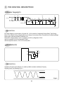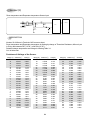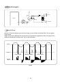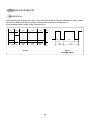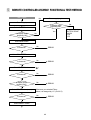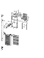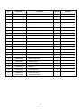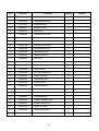
1
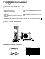
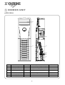
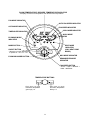
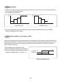
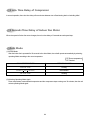
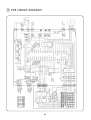
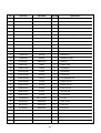
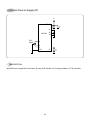
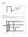
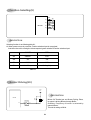
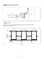
Service Manual
FLOOR STANDING AIR CONDITIONER
Model: DPB-280LH
DAEWOO ELECTRONICS CO., LTD.
OVERSEAS SERVICE DEFT.
Contents
CONTENTS
1. Installation Guide...........................................................................................2
2. Specification..................................................................................................5
3. Outline..........................................................................................................6
4. Operation .....................................................................................................8
5. Circuit Diagram...........................................................................................18
6. Refrigerant Cycle .........................................................................................35
7. Trouble Shooting..........................................................................................36
8. Exploded Diagram ......................................................................................43
1. INSTALLATION GUIDE
1 INSTALLATION PLACE
◆Indoor unit
◆Outdoor unit
• Flat and strong place in the room
• No obstacles in front of air in/out grille
• Easy place to connect drain hose to outside of room
• Easy place to connect copper tube with outdoor unit
• Secure enough distance from neighboring objects as
shown below.
• Secure enough distance from neighboring objects as
shown below.
• A place no reach of direct ray of sun (if necessary, shield the
light)
• No obstacles in front of air in/out grille
• A place having a drain out-let
• Easy place to connect copper tube with indoor unit
• Secure enough distance from neighboring objects as shown
below.
CAUTION : Do not hang the outdoor unit on the wall of building, in case of falling, it may cause a serious trouble and damage.
2 SPACE TO INSTALL
Secure enough space from the neighboring objects as shown below.
This is required to operate the unit efficiently.
10
cm
50
cm
10cm
100
cm
50cm
5cm
(Indoor unit)
(Outdoor unit)
◆ Specification and method of copper tube
• Connection method of copper tube is to make connection with flare nut at the end of the copper tube with a flare tool.
Flare specification
Nominal diameter
Lquid
3/8”
Gas
5/8”
B
Torque
Lquid
Gas
2
Unit: mm
A
12~12.4
18.6~19
B
9.52
15.88
Unit: mm
3/8”
5/8”
Torque
300Kg • cm
500Kg • cm
3 INSTALLATION OF INDOOR UNIT
1) Drain hose should maintain downward slope to outside of room.
2) Indoor unit should be fixed firmly with the bracket to avoid falling down.
The bracket has several holes to fix the unit any direction needed
(fore/back/right/left)
2
1
4 INSTALLATION OF OUTDOOR UNIT
1) Cushion rubbers absorb vibration of outdoor unit
2) The unit must be grounded for safety in accordance with local
electrical codes. (Grounding resistance should be under 100 ohms)
2
1
5 REFRIGERANT TUBE CONNECTION
IDU TERMINAL BLOCK
3
3
2
1
Y
N
L
220V/50Hz
CAUTION
• Use designated diameter and thickness of tube.
• Connect all tube as short as possible and fix firmly.
• Less than 3M of the difference of height between indoor
and outdoor unit is desirable.
• Fill up more refrigerant if the connection tube is longer
than 5M (50g/M).
(The refrigerant volume filled from the factory is suitable
for 5M connection)
• Be careful not to let in any dust or motes into the tube
when the tube passes the wall.
• When insulating the connection, use foam rubber or
equivalent.
3
2
1
Y
N
L
ODU TERMINAL BLOCK
(Connecting method)
3
2
1
Y
N
L
N
L
Spec
1.25mm2
1.25mm2
1.25mm2
1.25mm2
1.25mm2
1.25mm2
1.25mm2
2.0mm2
2.0mm2
2.0mm2
Color
BLUE
BLACK
RED
BROWN
BROWN
YEL/GRN
RED(or BLUE)
BLACK
YEL/GRN
WHITE
SIGNAL LINE
SIGNAL LINE
SIGNAL LINE
SIGNAL LINE
MAIN POWER (INDOOR)
MAIN POWER (INDOOR)
MAIN POWER (INDOOR)
MAIN POWER (OUTDOOR)
MAIN POWER (OUTDOOR)
MAIN POWER (OUTDOOR)
(Specification of harness)
6 ELECTRICAL WIRING
CAUTION
• Be sure to use designated wires and make it as short as possible
• Use an exclusive power supply for the air conditioner
• Use an electricity leakage interrupter having suitable capacity.
• Grounding resistance should be under 100 ohms and the grounding wire should be connected firmly to the
terminal of out door unit.
■ Wire connection of indoor and outdoor unit
• When connecting wires of indoor and outdoor unit, the numbers of terminal block and terminals of connecting wires should
match exactly as shown below.
• Terminals of connecting wires should be fixed firmly using wire fixing tool to the same direction of terminal board.
(Diagram of wire connection)
4
2. SPECIFICATIONS
◆DPB-280LH
MODEL
DPB-280LH
ITEM
Function
COOLING
HEATING
Class
T
Power
220~240V/ 50Hz
Capacity
W
8,200
8,200
Btu/h
28,000
28,000
l/h
-
-
Running Current
A
14
14
Power Input
W
2,800
2,800
Starting Current
A
Dehumidification
Electrical
Data
Compressor
-
Type
Scroll
Model
ZR36K3-PFJ-501
Capacitor
50µF/370V AC
Type
Indoor Unit
Outdoor Unit
Sirocco
Propeller fan
5µF/400V AC
8µF/370V AC
DE112
A2935BA010
Fan
Capacitor
Motor Model Number
Refrigerant
(R-22)
Control
Charge Q'ty
Capillary
g
2,000
Type
Flare
Connection
OD (Liquid/Suction)
Dimensions (W x H x D)
Net Weight
in(mm)
3/8” (9.52mm)
5/8” (15.88mm)
mm
500 x 1,830 x 350
872 x 675 x 325
kg
40
66
5
3. OUTLINE
1 INDOOR UNIT
◆DPB-280LH
4
5
3
2
7
6
1
No
1
2
3
4
5
6
7
Part Name
Connecting Hole
Evaporator
Suction Grille
Discharge Grille
Fan Blower
Joint (Gas)
Joint (Liquid)
Quantity
3
1
1
1
1
1
1
Description
ø60X100 (Left, Right, Back)
Heat Exchanger
Air Inlet
Air outlet
Sirocco Type
OD ø15.88mm
OD ø9.52mm
6
Remarks
2 OUTDOOR UNIT
◆DPB-280LH
No
1
2
3
4
5
6
7
8
9
10
Part Name
Service Valve (Liquid)
Service Valve (Gas)
Service Door
Fan Guard
Fan Blower
Condenser
Fan motor
Compressor
Earth Bolt
Connection Hole
Quantity
1
1
1
1
1
1
1
1
1
1
Description
OD ø9.52mm Flare Type
OD ø15.88mm Flare Type
Fan Protector
Propeller type
Heat Exchanger
Foor propeller fan
Depend on Models
Ground
Power & Control wire
7
Remarks
4. OPERATION
1 PARTS OF NAME AND FUNCTION
Indoor Unit
AIR OUT
- According to the operation mode, it
is opened/closed automatically.
MAIN CONTROLS/
REMOTE SENSOR
O
AUT
DE
MO
AIR IN
F
/OF
ON
D
EE
N SP
FA
ER
P
EE TIM
SL
N DIR
R/ EL
TE NC
EN CA
FA
- It is to suck warm air.
- There is an air filter inside this grille.
• The method to open the air suction
grille
Pull the upper side of grille with
both hands.
.
FA
N DIR
ILD
O/M
RB
TU
.
LCD REMOTE CONTROLLER
- Operative distance is within 7m from
the indoor unit.
- Use toward to the remote sensor
8
ROOM TEMPERATURE / DESIRED TEMPERATURE INDICATOR
- It displays current room temperature and desired room temperature.
FAN MODE INDICATOR
AUTO FAN SPEED INDICATOR
AUTO MODE INDICATOR
FAN SPEED INDICATOR
COOL MODE INDICATOR
TIMER/SLEEP INDICATOR
QUICK MODE
INDICATOR
ECONOMY MODE
INDICATOR
MODE BUTTON
HEAT MODE
INDICATOR
(ONLY HEAT PUMP
MODEL)
ON/OFF BUTTON
- Whenever you push this button.
It repeats on -> off -> on -> off.
MILD MODE INDICATOR
ECONOMY MODE BUTTON
DEHUMIDIFIER MODE
INDICATOR
FAN SPEED BUTTON
- AUTO -> LOW -> MIDDLE ->
HIGH -> NATURAL
TEMPERATURE BUTTONS
- Each time you push
this button, temperature
goes up by 1˚C.
- Each time you push
this button, temperature
falls by 1˚C.
9
Outdoor Unit
OUTDOOR UNIT AIR OUT
SERVICE VALVES(GAS TUBE)
SERVICE VALVES(LIQUID TUBE)
CAUTION
• Do not install the outdoor unit on
unstable place like outside wall of
building or outside of balcony. In case
of falling, it may cause serious trouble
and damage.
OUTDOOR UNIT AIR IN
- If there is any obstacle in front
of the grille, the efficiency of
the unit can be lowered.
10
2 REMOTE CONTROLLER
Name of Each Button
Display
Displays information
pertaining to unit.
AUTO
FAN SPEED Button
Press to select the fan speed
(Auto, High " ", Middle " ",
Low " ", Natural).
MODE Button
Press to cycle through the modes
(Auto/Quick/Cool/Fan/Dehumidifier/
Heat)
ON/OFF Button
Press to turn the unit
on or off.
TEMPERATURE Buttons
Press to raise or lower
the desired temperature.
MODE
FAN SPEED
SLEEP
FAN DIR.
FAN DIR.
Button
Press to select up/down
direction for fan.
FAN DIR.
TIMER
ON/OFF
ENTER/
CANCEL
TURBO/MILD
FAN DIR.
Button
Press to select left/right
direction for fan.
TURBO/MILD
Press to be more silent and
comfortable room condition
SLEEP Button
Press to set the unit for
the sleep mode.
TIMER ON/OFF Button
Press to set the unit off or on time.
(0.5, 1, 1.5, 2, 2.5, 3, 4, 5, 6, 8,
10, 12, 16, 20, 24hr)
TIMER ENTER/CANCEL Button
Press to enter a timer setting or
to cancel timer setting
COVER
Slide down to access most
of the remote buttons.
Slide down further to
access the battery
compartment.
11
3 REMOTE CONTROLLER DISPLAY
MODE Indicators (Auto/Quick/Cool/Fan/Dehumidifier/Heat)
Lights to indicate the mode selected.
AUTO
FAN Indicators
Lights to indicate
the fan speed.
FAN DIRECTION Indicators
Lights to indicate the
fan direction.
NATURAL Indicator
Lights to indicate the
speeds simulating a breeze.
TIMER Indicators
Lights to indicate the timer function mode.
TEMPERATURE & RESERVATION TIME lndicator
Lights to indicate the temperature or time.
Replacing Batteries
12
TIMER
ON/OFF
ENTER/
CANCEL
TURBO/MILD
+
2
Insert two “AAA” size
Alkaline batteries
following the polarity
diagram below.
–
1
Slide down the cover to
access most of the
remote buttons. Slide
down further to access
the battery compartment.
–
+
4 DESCRIPTION OF FUNCTIONS
OFF-Timer
If you set time in OFF-Timer Mode, the unit will stop at the set time.
ON
Unit ON
Unit OFF
OFF
SET Time
HOUR
ON-Timer
If you set time in ON-Timer Mode, the unit will run at the set time.
Unit ON
ON
OFF
Unit OFF
SET Time
HOUR
Control of Room Temperature
(1) Range of setting temperature: 18~32°C
(2) Setting temperature: Operating temperature of compressor
COMP (ON)
COMP (ON)
COMP (OFF)
COMP (OFF)
-1°C
0°C
+1˚C
-1°C
(RT-DT)
0°C
+1˚C
(DT-RT)
(HEATING)
(COOLING)
*RT: ROOM TEMPERATURE
DT: DESIRED TEMPERATURE
(3) During the time of test operating, Fan (Indoor, Outdoor) and Compressor is running regardless of room
temperature.
Buzzer
If the Indoor Unit Display receive the signal of Remote Controller, you can hear the signal "beep –" or "beep,
beep".
(1) In the case of receiving ON/OFF signal-“beep” “beep”
(2) And so on-“beep”
13
Fan Speed (Indoor Unit)
(1) Motor speed (high speed, middle speed, low speed).
(2) Remote controller setting fan speed. (Auto, L, M, H, Natural)
(3) Relation of operating mode between fan speed. (legned: X-no relation)
FAN ONLY
COOL
DEHUMI-
AUTO
QUICK
HEAT
DIFICATION
H
H
H
L
H
H
H
M
M
M
L
M
H
M
L
L
L
L
L
H
L
Auto
X
Auto
L
Auto
H
Auto
Natural
Natural
Natural
L
Natural
H
Natural
(4) Automatic Operation
If the unit is set in 'AUTO' mode, the unit operates automatically according to the room temperature to keep the
room temperature comfortable.
(COOLING)
H
M
L
0°C
1°C
2°C
(RT-DT)
3°C
(DT-RT)
(HEATING)
H
M
L
0°C
1°C
2°C
14
Sleep Mode
(1) When you are going to sleep, select sleep switch and the unit controls the room to the desired temperature.
(The unit will not operate after 4 hour)
(2) For changing the temperature.
DT
DT
+0.5°C
+0.5°C
–0.5°C
+0.5°C
–0.5°C
–0.5°C
0
0.5
1.0
HOUR
0
(COOLING CYCLE)
0.5
1.0
HOUR
(HEATING CYCLE)
(3) To cancel sleep mode, press the SLEEP button again or press the MODE button once.: the SLEEP
indicator will disappear in the display.
Frost Prevention of Indoor Unit
When the unit operates at low ambient temperature, frost may appear on the Evaporator. When the indoor coil
temperature is lower than -2°C at the end of 10 minutes of continuous compressor operation from the start, the
microcomputer of the unit stops the compressor to protect the unit from the frost. The control procedure for
indoor coil freeze protection.
1) The compressor and outdoor fan turn off.
2) Indoor fan operates according to user set speed.
3) The normal operation returns when the indoor coil
temperature is higher than 7°C or equal to 7°C.
ON
Compressor and
Outdoor Fan
OFF
-2°C
7°C
(Indoor coil temperature)
15
3 min. Time Delay of Compressor
In normal operation, there is a time delay of three minutes between turn off and turning back on including initial
3 Seconds Time Delay of Indoor Fan Motor
When the speed of indoor fan motor changes, there is a time delay of 3 seconds at each speed step.
Auto Mode
(1) In Auto Mode
After the indoor fan is operated for 20 seconds in the Auto Mode, the unit will operate automatically by selecting
operating Mode according to the room temperature
RT: Room temperature
DT: Desired
(
ROOM TEMPERATURE
OPERATING MODE
DT+3˚C < RT
Cooling
DT-2˚C < RT < DT+2˚C
Dehumidifier
DT -2°C > RT
Heating
)
(2) Selecting Operating Mode Again
Room temperature meets desired temperature and the compressor stops running over 30 minutes, then the unit
selects operating Mode again.
16
Dehumidification Mode
1 DT+1˚C < RT
Outdoor Fan, Compressor : ON
Indoor Fan : Low speed
2 DT-1˚C < RT < DT+1˚C
Outdoor Fan, Compressor : 3 min/ON, 5 min/OFF
Indoor Fan : Low speed
3 DT-1˚C > RT
Outdoor Fan, Compressor : OFF
Indoor Fan : Low speed
Air Discharge Direction
1. Press fan direction button to select fan direction
• Press desired fan direction button, "UP • DOWN" or "LEFT • RIGHT" control louver moves, press
again to stop
FAN DIR.
FAN DIR.
Quick Mode(Powerful Cooling & Heating)
(1) Cooling Mode
* When the room temperature is higher than 22˚C or
equal to 22˚C
1 Fan Speed: high speed (Fixed)
2 Air discharge direction: The control is available.
3 Set temperature: 18°C (Fixed)
(1) Heating Mode
* When the room temperature is lower than 22˚C
1 Fan Speed: high speed (Fixed)
2 Air discharge direction: The control is available.
3 Set temperature: 32°C (Fixed)
Self-Diagnostic Function
The control will contain diagnostic test to verify the integrity of the system.
(1) Error Code Display : RT (Room Temperature) LED
ERROR CODE
DISPLAY
ERROR CONTENTS
1
“E2”
Indoor unit sensor open or short
2
“E2”
Outdoor unit sensor open or short
3
“ E3 ”
Compressor, Electrical parts of
comp. Gas leak
17
5. CIRCUIT DIAGRAM
1 WIRE CONNECTION OF INDOOR AND OUTDOOR UNIT
◆ DPB-280LH
18
2 MAIN ELECTRIC PARTS
◆ DPB-280LH
Object/part No.
Manufacturer/trademark
Type/model
Technical data
Standard
Mark(s) of confirmity
Motor-compressor
Copeland
ZR36K3-PFJ
AC220-240V 50Hz R22
DEMKO
Outdoor fan motor
DMI
A2935BA010
AC 230V 50Hz
NONE
Indoor fan motor
O-YANG
DE112
AC 230V 50Hz
NONE
17AM035A5
AC 250V
Jaeil engineering
ST-16
AC 220-240V 50/60Hz
VDE
Namyang Precision
(Alter)
NYM-16H-1
AC 220-240V 50/60Hz
NONE
Stepping motor
Hyup jin precision
MSFCC20F02
DC 12V
NONE
Dual capacitor for
compressor and
outdoor fan motor
Samwha capacitor
37H08500B
8/50µF 370VAC
TUV, UL, CSA
Running capacitor
for indoor fan motor
Samwha capacitor
PEB-958
5µF 400VAC
TUV, UL, CSA
Terminal block
Donglim
DTB-8P
AC 300V 25A
NONE
Transformer
Namsung electronics DWA-5401FN
AC 220V/18VDC 50/60Hz
NEMKO
Reversing valve
Ranco japan
AC 220-240V 50Hz
NONE
Compressor heater
Young chang
AC 220V 40W
NONE
AC Control realy
Omron electronics
AC 220-240V 25A
VDE
Relay
Chung won electronics CS11-12H
AC 250V 5A
TUV, UL, CSA
Fuse
Triad electronics
50T
AC 250V 3.15A
VDE
X2 capacitor
Pilkor electronics
PCX2 335
AC 275V
VDE, N.S.
Photocoupler
Toshiba electronics
TLP560J
AC 250V
VDE
Varistor
Marcon electronics
TNR15G561K
504-616V 50A
UL
Triac
Toshiba electronics
SM3JZ47
600V 3A
UL
Thermal protector for Korea Taxas
fan motor
Instruments
Synchronous motor
V26110D
G7L-2A-TUB
19
3 PCB CIRCUIT DIAGRAM
20
NO
Part Code
Part Name
Quantity
1
3108803400
PIN
3
GP881206-2(187)
2
5FVLB3152L
FUSE
1
250V 50T 3.15A
3
3107000600
FUSE CLIP
2
AFC-520
4
3108802500
WAFER
1
YW396-03AVD
5
3108802600
WAFER
1
YW396-03AVD (RD)
6
3108802700
WAFER
1
YW396-03AVD (BK)
7
3108802900
WAFER
1
YW396-05AVD
8
3108803000
WAFER
1
YW500-02V
9
3108801900
WAFER
1
SMW250-04
10
3108801910
WAFER
1
SMW250-04(RD)
11
3108802000
WAFER
1
SMW250-06
12
3108804100
WAFER
1
SMW250-07
13
3108802200
WAFER
1
SMW250-10 (RD)
14
D15G561K--
VARISTOR
1
15G561K
15
DZN4004A--
DIODE
6
1N4004 TAPE
16
CCXE1H102Z
C-CERA
1
102Z,50VDC
17
CCXE1H103M
C-CERA
1
103Z,50VDC
18
CCXE1E104M
C-CERA
8
104Z,25VDC
19
CDXE1H104M
C-MULTI
1
104Z,CR0561B-Z5U
20
CEXE35338M
C-ELEC
1
3300uF 35V SD
21
CEXE1V108C
C-ELEC
1
1000uF 35V SD
22
CEXE1E477C
C-ELEC
1
470uF 25V SD
23
CEXE1C106C
C-ELEC
1
10uF 50V SS
24
CEXE1C475C
C-ELEC
1
4.7uF 50V SS
25
CN4XD104M
CAPA. ARRAY
1
F4 104Z
26
RN-4K1272F
RESISTOR
2
1/4W-12.7KF
27
RD-4K103J-
RESISTOR
10
1/4W-10KJ
28
RD-4K842F-
RESISTOR
2
1/4W-8.4KF
29
RD-4K562J-
RESISTOR
2
1/4W-5.6KJ
30
RD-4K102J-
RESISTOR
3
1/4W-1KJ
31
RD-4K301J-
RESISTOR
4
1/4W-300J
32
RD-4K101J-
RESISTOR
1
1/4W-100J
21
Specification
NO
Part Code
Part Name
Quantity
33
RD-2K200J-
RESISTOR
1
1/2W-20J
34
RD-2K390J-
RESISTOR
2
1/2W-39J
35
RD-2K121J-
RESISTOR
5
1/2W-150J
36
RD-2K102J-
RESISTOR
1
1/2W-1KJ
37
CLV-B3104M
C-LINE ACROSS
1
275V 104K
38
4EFR-37071
SNUBBER
1
0.1UF 120 300V
39
3105796100
HEAT SHINK
1
33(H)X23X17
40
3106002900
WASHER
1
HEAT SINKøÎ
41
3105698200
BUZZER
1
DP-2520BA
42
52C131J003
COIL
1
130uH 3A
43
3109400100
JUMPER
32
10mm
44
3109400100
JUMPER OPTION
1
10mm
45
3104398700
PCB MAIN
1
162X169
46
5SC0101128
RELAY
5
CS11-SH12
47
1KA7812AP-
IC REGULATOR
1
KIA7812P
48
1KA7805AP-
IC REGULATOR
1
KIA7805P
49
TKRC102M--
TR
2
KRC102M
50
1KA7042P--
IC RESET
1
KIA7042P
51
4850103610
RESONATOR
1
CST8.00MGW
52
TSM3JZ47--
TRIAC
1
SM3JZ47
53
1TLP560J--
PHOTO COUPLER
1
TLP560J
54
13GS87PH46
IC MICOM
1
TMP87C846AN
55
13GT4051B-
IC MUX
1
TC4051BP
56
13GT62004A
IC DRIVE
2
TD62004AP
57
13GT62783A
IC DRIVE
1
TD62783AP
22
Specification
4 PCB DRIVING DESCRIPTION
Power Supply(1)
AC 220V
FUSE1
12V
VAR
D1
275V
104K
D2
CC1
CE1
IC2
7812
CC2
5V
CE2
+
3.15A
D4
D3
104
G
VI VO
+
104
35V
1000µF
25V
470µF
IC3
7805
VI VO
CC3
G
CL1
CE3
+
104
16V
100µF
POWER TRANS
DESCRIPTION
DC Power Supply in circuit needs +12V and +5V. +12V is used for Compressor Driving Relay, Triac Driving
Photo Triac, Buzzer Driving, Stepping Motor. AC voltage of secondary Power Transformer is rectified by Bridge
Diode, and it is filtering by Main Condensor CE1.
Filtered DC voltage is about +18V, is regulated +12V DC by Regulator IC7812.
And it is regulated +5V DC by Regulator IC7805.
VAR is serge filter and CC1, CC2, CC3 is Noise filter.
Oscillator(2)
5V
19
OSC
20
CC13
104
8M
DESCRIPTION
Oscillatory Frequency drive Micom, it is made up 8MHz resonator oscillatory Freqency.
Ocillatory wave is as following Fig 2-1.
VDD-10%
VSS+10%
Fig 2-1
23
Sensor(3)
Room temperature and Evaporator temperature Sensor Input
CN10
EVA
PT-K43C
Room
1
2
3
4
5V
R32
5
R37
12.7K
23
MICOM
330
CA1
104
MUX
SMW250-04
R31
PT-K43C
1
330
R38
12.7K
CA1
104
DESCRIPTION
Number 23 of Micom is Terminal of A/D convertor Input.
Room temperature and Evaporator temperature is sensing by change of Thermister Resistance, Micom is put
in 5V by ratio between R37 (12.7KΩ) and R38 (12.7KΩ).
Relation between temperature and voltage is following Table 3-1.
CA1 is Noise filter.
Resistance & Voltage of the Sensor
temp(°C) resistance1(Ω)
–10
–9
–8
–7
–6
–5
–4
–3
–2
–1
0
1
2
3
4
5
6
7
8
9
10
11
12
13
14
15
16
54,769
52,070
49,579
47,272
44,116
42,190
40,390
37,902
36,368
34,235
32,279
31,064
29,358
27,781
26,794
25,400
24,101
22,888
21,752
20,687
19,685
19,050
18,143
17,286
16,476
15,708
14,979
Vout(V)
0.941
0.980
1.020
1.059
1.118
1.157
1.196
1.255
1.294
1.353
1.412
1.451
1.510
1.569
1.608
1.667
1.725
1.784
1.843
1.902
1.961
2.000
2.059
2.118
2.176
2.235
2.294
temp(°C) resistance1(Ω)
17
18
19
20
21
22
23
24
25
26
27
28
29
30
31
32
33
34
35
36
37
38
39
40
41
42
43
14,288
13,629
13,002
12,405
12,021
11,468
10,939
10,432
9,947
9,634
9,182
8,890
8,467
8,060
7,79,
7,415
7,168
6,809
6,577
6,239
6,020
5,806
5,597
5,392
5,094
4,901
4,711
24
Vout(V)
2.353
2.412
2.471
2.529
2.569
2.627
2.686
2.745
2.804
2.843
2.902
2.941
3.000
3.059
3.095
3.157
3.196
3.255
3.294
3.353
3.392
3.431
3.471
3.510
3.569
3.608
3.647
temp(°C) resistance1(Ω)
44
45
46
47
48
49
50
51
52
53
54
55
56
57
58
59
60
61
62
63
64
65
66
67
68
69
70
4,526
4,435
4,255
4,080
3,908
3,739
3,656
3,493
3,332
3,253
3,098
3,021
2,870
2,795
2,721
2,576
2,504
2,433
2,363
2,293
2,156
2,088
2,020
1,954
1,888
1,822
1,758
Vout(V)
3.686
3.706
3.745
3.784
3.824
3.863
3.882
3.922
3.961
3.980
4.020
4.039
4.078
4.098
4.118
4.157
4.176
4.196
4.216
4.235
4.275
4.294
4.314
4.333
4.353
4.373
4.392
Triac Driving(4)
12V
N
L1
1
TLP561
1
PT1
32
7
L
130µH
3A
MICOM
T1
SM3JZ47
IC4
KID 65004
AC 220V
2
SN1
0.1µF
120Ohm
2
10 R2
TO MOTOR
1K
1/2W
DESCRIPTION
Number 32 Terminal of Micom is put out Pulse Output, by way of Buffer it is driving Photo Triac is supplied
Trigger Signal.
Trigger Test of Triac is detected Zero Cross Part of AC input and it is triggered from Zero Cross part to Time
delay part according to Fan Speed. (Ref. Fig 4-1) SN1 is Snubber.
AC220V
TRIGGER
LOW SPEED
LOW
SPEED
MEDIUM SPEED
SPEED
MIDDLE
MOTOR
INPUT
Fig 4-1
25
HIGH SPEED
SPEED
HIGH
Remote Controller(5)
DESCRIPTION
Signal from Remote Controller put in only Control Data Signal at Micom Terminal of Number 33, which is gotten
fid of Carrier (38KHz) from Receive Module. Signal Wave repeat third as following Fig 5-1.
But in Secondary Wave Custom Code is Reversed Face.
9ms
4.5ms
16bit
24bit
8bit
16bit
0.56ms
LEADER CODE
CUSTOM
CODE
DATA
CODE
CHECK
SUM
TAILER
1.12ms
bit 0
1.69ms
2.25ms
bit 1
Fig 5-2
BIT STRUCTURE
Fig 5-1
26
0.56ms
Micom Power Supply(7)
5V
VDD 42
CE4
10µF
16V
+
CC5
104
41
MICOM
OSC
8MHz
40
39
19
20
21
VSS
22
CC7
104
DESCRIPTION
MICOM Power is supplied 5V at Number 42 using VDD, Number 19, 20 Using Oscillator, CC7 is noise filter.
27
Reset(8)
5V
R4
5.6K
IC6
7042P
+
CE5
4.7µF
50V
MICOM
18
DESCRIPTION
Voltage less than about 0.8V put in Micom Terminal of Number 18 and then Micom reset. Reset IC detect
Power ON and Voltage less than 4.25V, and then send Reset Signal.
Vcc (+5V)
4.25V
t
DELAY TIME
FOR POWER ON
H
RESET
L
t
POWER
ON
28
Function Selecting(9)
R22
27
26
MICOM
25
JS1
R23
JS2
R24
JS3
R25
JS4
24
DESCRIPTION
Selecting function is as following table 9-1.
✽ When power source is put at first, Funtion selection input is recognized.
And when the unit is running the microcomputer ignore variation of funtion selection input.
SHORT
OPEN
JS1
SIMPLE
LCD
JS2
132
180
JS3
MILD
HIGH
JS4
Heat Pump
Cooling Only
Table 9-1
Buzzer Driving(10)
VCC
12V
DESCRIPTION
MICOM
R7
1K
Micom 34 Terminal put out Buzzer Driving Pulse,
its output is driving Buzzer through Buffer.
Ocillatory Frequency of buzzer is selected by
internal Micom.
This unit is setting at 2KHz.
BZ
KID 65004
34
6
11
29
Zero Crossing Detect(11)
VCC
R5
10K
2
TR2
KRC102M
D5
2
1
R6
1K
MICOM
31
3
R3
5.6K
1
D6
2
TRANS
OUTPUT
1
CC8
103
2
1
DESCRIPTION
It detect Zero Cross part of Trans output voltage, Transistor TR2 is used to put in the Micom.
Detail Driving is as following Fig 11-1.
AC18V
The
Number
31 of H
Micom
terminal
L
DETECT POINT
Fig 11-1
30
Stepping Motor Driving(12)
12V
CN11
1
IC4
MICOM
B+
2
9
3
Ø1
10
4
Ø2
11
5
12
6
M1
FOR SWING
Ø3
Ø4
KID65004
DESCRIPTION
There are one Stepping Motor for Flap (up and down) and it is used 4 face Drive Method.
It is driving as following Fig 12-1. (Ring Count Method of 8 Status)
Ø4
Ø3
Ø2
Ø1
(Normal Rotating)
(Reversed Rotating)
Fig 12-1
31
MICOM
Display Output
1 P77(HSO)
VDD 42
2 P76(HSCK)
(XTOUT)P22 41
3 P75(SO)
Key Input
(XTIN)P21 40
4 P74(SI)
(INT5/STOP)P20 39
5 P73(SCK)
P17 38
6 P72(PDO/PWM)
P16 37
Compressor Heater Driving
7 P71(INT4)
(TC2)P15 36
8 P70(INT3/TC3)
(PPG)P14 35
Outdoor Unit Motor Driving
9 P07
(DVO)P13 34
Buzzer Driving
10 P06
(INT2/TC1)P12 33
Remocon Input
11 P05
(INT1)P11 32
Indoor Unit Motor Driving
12 P04
(INTO)P10 31
Zero Crossing Detect
13 P03
(AIN7)P67 30
Display Driving
14 P02
(AIN6)P66 29
Auto Swing Driving
15 P01
(AIN5)P65 28
4-way Valve Driving
16 P00
(AIN4)P64 27
17 TEST
(AIN3)P63 26
18 RESET
(AIN2)P62 25
19 XIN
(AIN1)P61 24
20 XOUT
(AIN0)P60 23
Stepping Motor
Compressor Relay Driving
Reset Circuit
Oscillation
21 (VASS)VSS
VAREF 22
32
Fuction Select
Temperature Sensor Input
DARLINGTON ARRAYS (KID65004)
16 OUT 1
15 OUT 2
14 OUT 3
13 OUT 4
12 OUT 5
11 OUT 6
10 OUT 7
9 COMMON FREE
WHEELING DIODES
COMMON
INPUT
OUTPUT
10.5K‰
7.2K‰
3K‰
IN1 1
IN2 2
IN 3 3
IN 4 4
IN5 5
IN6 6
IN7 7
GND 8
GND
VOLTAGE REGULATOR (KIA7805AP-5VDC)
SCHEMATIC DIAGRAM
INPUT
100K
100
100
500
10K
240
200
3.3
K
1
2
3
1.4
K
OUTPUT
2K
6K
2.7
K
0.3
0.19K
28K
30pF
5K
500
6K 1K
5K
Fin 2 is ground
for Cose 221A.
Case is ground
for Case 1.
GND
VOLTAGE REGULATOR (KIA7812AP-12VDC)
10K
INPUT
10K
210
16K
100
300
200
36K
64K
300
50K
520
60K
012
40
pF
50
200
OUTPUT
26K
Pin 1. INPUT
2. GROUND
3. OUTPUT
20K
29K
20K
GND
(Equivalent Ciircuit)
33
RESET IC (KIA 7042P)
1 VCC
KIA70
42P
3 OUT
2 GND
INPUT
GROUND
OUTPUT
OUTLINE
34
6. REFRIGERANT CYCLE
INDOOR UNIT
OUTDOOR UNIT
HIGH PRESSURE SWITCH
INDOOR
HEAT EXCHANGER
M
UNION
FAN
M
SERVICE VALVE
FILTER
OUTDOOR
HEAT EXCHANGER
DISTRIBUTER
COMPRESSOR
CAPILLARY TUBE
Note) If the pipe length exceeds the standard length, add 30g of refrigerant per extra meter.
Contents
Model Name
Capillary tube(내경×L×수량)
Cooling
Heating
IDØ1.4 x 1000mm(6.0l/min) x 5EA
ODØ2.0 x 250mm
Charge Quantity
2000 g
35
Trouble
Is the
unit display
normal?
Is the power
applied to the
unit
Outdoor unit does
not run?(note. 1)
Is the
power normal?
check the voltage between
L & N of terminal
block
Does
the compressor run
normally?
NO
YES
NO
YES
Check the failure
code according to
the self diagnostic
(note 2)
Check the wiring of indoor
YES
press the power ON/OFF
button on remote controller
YES
Is the unit
display
mormal?
NO
36
7. TROUBLE SHOOTING
YES
Indoor unit does
not run(note 1)
Check power supply mains
or interconnection wires
YES
YES
NO
NO
YES
NO
NO
Does the
beeper beep two
times?
Normal
check the
connecting
point of
magnetic
contactor
YES
NO
Is the display
all off?
NO
Does
control PCB
status LED repeat one
second "on and
off"?
• control PCB fault
• Micom or reset
IC fault
YES
YES
check the failure
code according to
the self-diagonostic
(note 2)
• Check the connector on display
PCB connected to control PCB
• Check the display PCB itself
• Check the remote signal receiver
• Check the connection between signal
receiver and control PCB
1 Neither Indoor Unit nor Outdoor Unit Runs
The power is applied to the unit
Rating voltage
under 90%
Check the voltage between L and
N of terminal block
Check the
Breaker or Fuse
Rating voltage more than 90%
No
Check the indoor unit display
is the display all off?
Yes
Press the ON/OFF switch of
Remote Control
No
Self Diagnostic
function is ON
Yes
No
Check according to
self Diagnostic function
Is the indoor unit display all off?
Control P.C.B defect
Pull out the power plug
and then insert the power plug
after 5 second
Control P.C.B is normal
Recheck from the beginning
37
2 Outdoor Unit Runs but Indoor Unit Do Not Run
Check rotation of indoor fan
NO
Check the Fan Motor
bearing and fan
Rating voltage
Check the power P.C.B.
Rotate indoor fan by hand
YES
Check input Voltage of Fan
Motor connector at power P.C.B
under 90%
The circuit for triac control
Rating Voltage more than 90%
Open or short
Check the winding resistance of
Indoor unit fan motor
Normal
Check the fan motor capacitor
Check the connecting wire of
indoor fan motor
Run again
38
Change of fan motor
3 Outdoor Fan Do Not Run
Check the voltage between L and
N of outdoor unit terminal
Rating voltage
Check the voltage between L and
N of indoor unit terminal
Rating voltage
Check the voltage between L and
2 of outdoor unit terminal
Rating voltage
under 90%
under 90%
under 90%
Check outdoor fan motor individually
39
Check the
connecting wire
Check the wiring
and voltage
within doors
Check the
connecting wire
4 Only Compressor Do not Run
- Check the following at cooling mode
Rating voltage
Check the voltage between N and
Y of outdoor unit terminal
less than 90%
Check the connecting
wire between indoor
and outdoor.
Rating voltage more than 90%
Rating voltage
Check the voltage between N and
Y of indoor unit terminal
less than 90%
Check the control P.C.B
the circuit for relay
driving.
Rating voltage more than 90%
Check the magnetic contactor
NG
Change the magnetic
contactor.
Open or Short
Change the
compressor.
Check the wiring of outdoor unit
Check the compressor
(Check the winding resistance)
OK
Check the compressor capacitor
40
5 REMOTE CONTROLLER ASSMBLY FUNCTIONAL TEST METHOD
TEST START
No
Power supply again
Power Supply
Is Display at the
beginning ON?
Select ON/OFF button
Yes
Is Display at the
beginning ON?
No
Select Mode button
Is it normal?
No
ERROR
Select FAN SPEED button
Is it normal?
Select FAN DIR. button
Is it normal?
Is display at the
begining ON?
Select TEMP. Button (▲,▼)
Is it normal?
No
ERROR
▲
(▼)
No
ERROR
No
ERROR
(Whenever you selectted Temp.
Button, it is changed by 1°C (18~32°C)
No
ERROR
Select ON/OFF button
41
No
Check the Following
BATTERY SPRING
MICOM
PCB
LCD
Is LCD display OFF?
No
ERROR
Select TIMER ON Button
Is it normal
No
ERROR
Select Timer Enter Button
TIMER display?
No
ERROR
Select CANCEL Button
Is all display OFF?
No
ERROR
Select ON/OFF Button
Select OFF (Timer) Button
Is it normal?
(0.5~24 HOUR)
No
ERROR
Select SLEEP Button
SLEEP MODE
Display ON?
No
ERROR
Select SLEEP Button
Is display at the
beginning ON?
No
ERROR
TEST OK!
42
8. EXPLODED DIAGRAM
1 INDOOR UNIT
NO
Part Code
Part Name
1
3100090100
ASSY CABNET BODY
1
2
3100042301
BASE MOTOR ASSY
1
3
3100602801
BRACKET PAN DRAIN
1
4
3108008600
MOTOR IDU
1
5
3101501900
CUSHION MOTOR
3
6
3106600210
SCROLL HOUSING
1
7
3106903100
CAPACITOR MOTOR IDU
1
8
3100025000
BLOWER ASSY
1
9
3105200300
WASHER STOPPER
1
10
3100301600
BASE
1
11
3101501100
CUSHION BASE
4
12
3100503901
BOX CONTROL
1
13
3104398800
ASSY MAIN PCB
1
14
5EPK560120
TRANS
1
15
3100042501
PAN DRAIN ASSY
1
16
3100042603
EVAPORATOR ASSY
1
17
3100042802
PIPE DISCHARGE ASSY
1
18
3100042903
PIPE SUCTION ASSY
1
19
3105100400
SPRING SENSOR
1
20
3102707930
HARNESS COIL SENSOR
1
21
3101402700
COVER EVAP. L
1
22
3100048310
ASSY COVER EVAP. R
1
23
3100043000
COVER EVAP. TOP ASSY
1
24
3107000400
CLIP THERMO
1
25
3100087200
COVER HOUSING ASSY
1
26
3104202700
PANEL CONTROL
1
27
3105501800
WINDOW
1
28
3104301010
ASSY CONTROL PCB
1
29
3103401510
KNOB SELECTION
1
30
3103401610
KNOB POWER
1
31
3100090620
ASSY PANEL FRONT
1
32
3100604700
BRACKET FRONT L
1
44
Quantity
Remarks
NO
Part Code
Part Name
33
3100604800
BRACKET FRONT R
1
34
3102201600
FRAME DISCHARGE
1
35
310P40086E
SWING MOTOR ASSY
1
36
3108005300
MOTOR STEPPING
1
37
3101101300
CASE MOTOR
1
38
3100702100
BUSHING MOTOR
1
39
3106501430
BLADE HORIZONTAL 1
5
40
3106501530
BLADE HORIZONTAL 2
1
41
3107801000
LINK GUIDE R
1
42
3107802200
LINK M
1
43
3106700100
CAM
1
44
3106301100
BAR VERTICAL
1
45
3106503000
BLADE VERTICAL
6
46
3101203400
PUSH MOUNT TIE
2
47
3101408000
COVER BOX CONTROL
1
48
3100090200
ASSY COVER TOP
1
49
3102403720
GRILLE SUCTION
1
50
3102500901
GUIDE FILTER L
1
51
3102501001
GUIDE FILTER R
1
52
3107900100
MAGNET
4
53
3104504700
PLATE MAGNET
8
54
3100056510
FILTER AIR ASSY
1
55
3108912340
TERMINAL BLOCK
1
45
Quantity
Remarks
2 OUTDOOR UNIT
NO
Part Code
Part Name
1
3100041704
BASE PAN PAINT ASSY
1
2
3107103000
COMPRESSOR ASSY
1
3
3107103200
CUSHION COMP
4
4
7400208411
WASHER PLAIN
4
5
7392801211
NUT LOCK
4
6
3102800300
CRANKCASE HEATER
1
7
3100031223
CONDENSER ASSY
1
8
3102402100
GRILLE COND
1
9
3100041100
GUIDE POST P/T ASSY
1
10
3100041201
BRK SERVICE P/TAS
1
11
3105401300
SERVICE VALVE G
1
12
3105401200
SERVICE VALVE L
1
13
3106002300
BOLT HEX
4
14
3100086810
PIPE REVERSING ASSY
1
15
3100079310
PIPE FILTER ASSY
1
16
3101407900
COMP COVER
1
17
3100031702
PLT PARTITION ASSY
1
18
3104201601
PANEL CONTROL
1
19
3108912340
TERMINAL BLOCK
1
20
5SC0202700
POWER RELAY
1
21
3109508000
CAPACITOR DUAL
1
22
3105300400
SUPPORT MOTOR
1
23
3108008500
MOTOR ODU
1
24
3101802001
FAN PROPELLER
1
25
3100031400
CABINET FRONT P/T AS
1
26
3100031500
CABINET SIDE P/T AS
1
27
3100041400
PANEL TOP ASS’Y
1
28
3102102000
GRILLE DISCHARGE
1
29
3101402500
COVER SERVICE
1
47
Quantity
Remarks
DAEWOO ELECTRONICS CO., LTD.
686, AHYEON-DONG MAPO-GU SEOUL, KOREA
C.P.O. BOX 8003 SEOUL, KOREA
TELEX: DWELEC K28177-8
CABLE: “DAEWOOELEC”
FAX: 02) 360-8184
TEL: 02) 360-8182/8178~9
http://www.dwe. daewoo.co.kr
PRINTED DATE: APR.1999