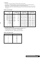
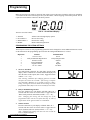
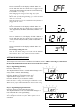
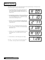
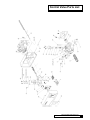
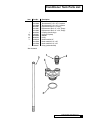
1
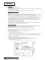
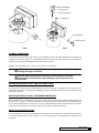
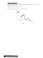
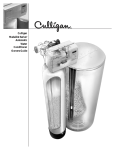
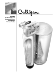
Cat. No. 01882292
Rev. E 09/17/02
DCO # 4625
Installation and
Operating
Instructions
with Parts List
CULLIGAN
MEDALLIST SERIES™
AUTOMATIC
WATER CONDITIONER
MODELS FROM 2002
©2002 Culligan International Company
Printed in USA
Attention Culligan Customer:
The installation, service and maintenance of this equipment should
be rendered by a qualified and trained service technician. Your local
independently operated Culligan dealer employs trained service and
maintenance personnel who are experienced in the installation, function and repair of Culligan equipment. This publication is written specifically for these individuals and is intended for their use.
We encourage Culligan users to learn about Culligan products, but
we believe that product knowledge is best obtained by consulting
with your Culligan dealer. Untrained individuals who use this manual
assume the risk of any resulting property damage or personal injury.
WARNING - PRIOR TO SERVICING EQUIPMENT, DISCONNECT POWER SUPPLY TO PREVENT ELECTRICAL SHOCK.
WARNING - IF INCORRECTLY INSTALLED, OPERATED OR
MAINTAINED, THIS PRODUCT CAN CAUSE SEVERE INJURY.
THOSE WHO INSTALL, OPERATE, OR MAINTAIN THIS PRODUCT SHOULD BE TRAINED IN ITS PROPER USE, WARNED OF
ITS DANGERS, AND SHOULD READ THE ENTIRE MANUAL
BEFORE ATTEMPTING TO INSTALL, OPERATE OR MAINTAIN
THIS PRODUCT.
IF THIS EQUIPMENT IS TO BE USED IN THE TREATMENT OF DRINKING WATER, THE WATER MUST BE
MICROBIOLOGICALLY SAFE.
CULLIGAN INTERNATIONAL COMPANY
One Culligan Parkway
Northbrook, Illinois 60062-6209
847.205.6000
Installation and
Operating
Instructions
with Parts List
CULLIGAN
MEDALLIST SERIES™
AUTOMATIC
WATER CONDITIONER
MODELS FROM 2002
Table of Contents
Page
Introduction ............................................................... 2
Specifications ........................................................... 3
Preparation ............................................................... 4
Installation ................................................................ 6
Settings .................................................................. 12
Programming .......................................................... 15
Manual Cycling ........................................................ 20
Service Check .......................................................... 21
Operation ................................................................. 22
Sanitizing Instructions .............................................. 24
Parts List ................................................................. 25
Introduction
The Culligan Medallist Series™ Water Softeners are tested and validated by
WQA and certified by UL against ANSI/NSF Standard 44 for the effective
reduction of calcium and magnesium along with Barium and Radium 226/228*.
Because the ability of the unit to remove barium and radium is based upon
reducing hardness to less than 1.0 grains per gallon, effective hardness
reduction should be periodically verified. Hardness sample kits are available
through your Culligan dealer.
ANSI/NSF 44
Water Softener
81WN
For installations in Massachusetts, Massachusetts Plumbing Code 248 CMR shall be adhered to. Consult your
licensed plumber for installation of this system.
SAFE PRACTICES
Throughout this manual there are paragraphs set off by special headings.
NOTICE: Notice is used to emphasize installation, operation or maintenance information which is important, but
does not present any hazard.
Example: NOTICE: The nipple must extend no more than 1 inch above the cover plate.
CAUTION: Caution is used when failure to follow directions could result in damage to equipment or
property. Example:
CAUTION: Disassembly while under water pressure can result in flooding.
WARNING: Warning is used to indicate a hazard which could cause injury or death if ignored. Example:
WARNING! ELECTRICAL SHOCK HAZARD! UNPLUG THE UNIT BEFORE
REMOVING THE COVER OR ACCESSING ANY INTERNAL CONTROL PARTS.
SERIAL NUMBERS
The control valve serial number is located on the back of the control.
The media tank serial number is located on the top surface of the tank.
NOTICE: Do not remove or destroy the serial number. It must be referenced on request for warranty repair or
replacement.
This publication is based on information available when approved for printing. Continuing design refinement
could cause changes that may not be included in this publication.
* Verified utilizing hardness surrogate per ANSI/NSF Standard 44.
2
CULLIGAN MEDALLIST SERIES
Specifications
CULLIGAN MEDALLIST SERIES™ WATER CONDITIONER WITH
TIMECLOCK OR SOFT-MINDER® METER
8" Model
5-cycle Reinforced
Thermoplastic
Overall Conditioner Height
51 in.
1,295 mm
Media Tank Dimensions
8 x 44 in.
(Dia. x Ht.)
203 x 1,118 mm
Salt Storage Tank Dimensions
16 x 43 in.
(Dia. x Ht.)
457 x 1,092 mm
18 x 43 in.
457 x 1,092 mm
Exchange Media, Type & Quantity Cullex® Media, 0.7 ft3
Underbedding, Type & Quantity
Cullsan® Underbedding,
6 lb.
Exchange Capacity @ Salt
18,300 gr @ 4 lb.
Dosage Per Recharge1
25,100 gr @ 9 lb.
Control Valve Type
27,500 gr @ 12 lb.
4 lb. salt dosage:
4570 gr./lb.
Freeboard to Media2
20.5 - 21.5 in.
Freeboard to Underbedding3
42.0 - 42.5 in.
Salt Storage Capacity
250 lb. or 375 lb.
Rated Service Flow @ Pressure Drop
5.9 gpm @ 12 psi
Total Hardness, Maximum
75 gpg
Total Iron, Maximum (dissolved) 5 ppm
Hardness to Iron Ratio, Minimum 8 gpg to 1 ppm
140 mg/L to 1 mg/L
Operating Pressure
20 - 125 psi
140 - 860 kPa
Operating Pressure (Canada)
20 - 90 psi
140 - 620 kPa
Operating Temperature
33 - 120°F
1 - 50°C
Electrical Requirements
24V/60 Hz
Electrical Power Consumption,
3 Watts/35 Watts
Min./Max.
Drain Flow, Maximum4
1.1 gpm
Recharge Time, Average
85 min.
Recharge Water Consumption
23.3 gal.
Efficiency at Rated Salt Dosage5
1
2
3
4
5
30 Model
5-cycle Reinforced
Thermoplastic
49 in.
1,245 mm
10 x 40 in.
254 x 1,016 mm
18 x 43 in.
457 x 1,092 mm
45 Model
5-cycle Reinforced
Thermoplastic
63 in.
1,600 mm
10 x 54 in.
254 x 1,372 mm
18 x 43 in.
457 x 1,092 mm
Cullex Media, 1.0 ft3
Cullsan Underbedding,
8 lb.
20,200 gr @ 5 lb.
Cullex Media, 1.5 ft3
Cullsan Underbedding,
8 lb.
24,900 gr @ 6 lb.
29,400 gr @ 11 lb.
39,200 gr @ 14 lb.
35,000 gr @ 17 lb.
5 lb. salt dosage
4050 gr./lb.
17 - 18 in.
39.6 - 40.1 in.
375 lb.
7.2 gpm @ 12 psi
99 gpg
5 ppm
8 gpg to 1 ppm
140 mg/L to 1 mg/L
20 - 125 psi
140 - 860 kPa
20 - 90 psi
140 - 620 kPa
33 - 120°F
1 - 50°C
24V/60 Hz
3 Watts/35 Watts
43,500 gr @ 20 lb.
6 lb. salt dosage
4150 gr./lb.
19.75 - 21.75 in.
53.8 - 54.3 in.
375 lb.
7.0 gpm @ 13 psi
99 gpg
5 ppm
8 gpg to 1 ppm
140 mg/L to 1 mg/L
20 - 125 psi
140 - 860 kPa
20 - 90 psi
140 - 620 kPa
33 - 120°F
1 - 50°C
24V/60 Hz
3 Watts/35 Watts
2.0 gpm
64 min.
61 gal.
2.1 gpm
64 min.
65 gal.
Capacities and corresponding salt dosages pertain to low hardness waters. Capacities given per recharge
Measured from top of media to top of inlet fitting (backwashed and drained)
Measured from top of underbedding to top of inlet fitting
Backwash at 120 psi (830 kPa)
Efficiency rating only valid at stated salt dosage on softminder models and is efficiency rated according to ANSI/NSF
SPECIFICATIONS
3
Preparation
COMPONENT DESCRIPTION
The water conditioner is shipped from the factory in a minimum of four cartons. Remove all components from their
cartons and inspect them before starting installation.
Control Valve Assembly - Includes the 5-cycle regeneration control valve and the Accusoft® Microprocessor. A
small parts pack will contain additional installation hardware. An Owner’s Guide is included.
Media Tank - Includes the media tank complete with Cullex® ion exchange resin, underbedding and outlet manifold.
Salt Storage Tank Assembly - Includes salt storage container with support plate and Dubl-Safe™ brine refill valve
and chamber.
Bypass Valve - Includes the Cul-Flo-Valv®, interconnecting couplings, and the screws necessary for assembly.
TOOLS AND MATERIALS
The following tools and supplies will be needed, depending on installation method. Observe all applicable codes.
All Installations
• Safety glasses
• Phillips screwdrivers, small and medium tip.
• Gauge assembly (PN 00304450 or equivalent)
• Silicone lubricant (PN 00471507 or equivalent) - DO NOT USE PETROLEUM-BASED LUBRICANTS
• A bucket, preferably light-colored
• Towels
Special Tools
• Torch, solder and flux for sweat copper connections
• Threading tools, pipe wrenches and thread sealer for threaded connections.
• Saw, solvent and cement for plastic pipe connections.
Materials
• Brine line, 5/16” (PN 00303128 or equivalent)
• Drain line, 1/2” (PN 00303082, gray, semi-flexible; or PN 00-3319-46, black, semi-rigid; or equivalent)
• Thread sealing tape
• Pressure reducing valve (if pressure exceeds 125 psi [860 kPa], PN 00490900 or equivalent)
• Pipe and fittings suited to the type of installation
• Water softener salt (rock, solar or pellet salt formulated specifically for water softeners)
APPLICATION
Water quality - Verify that raw water hardness and iron are within limits. Note the hardness for setting the salt
dosage and recharge frequency.
Iron - Iron is a common water problem. The chemical/physical nature of iron found in natural water supplies is
exhibited in four general types.
1. Dissolved Iron - Also called ferrous or "clear water" iron. Up to 5 ppm of this type of iron can be removed from the
water by the same ion exchange principle that removes the hardness elements, calcium and magnesium. Dissolved
iron is soluble in water and is detected by taking a sample of the water to be treated in a clear glass. The water in
the glass is initially clear, but on standing exposed to the air, it may gradually turn cloudy or colored as it oxidizes.
2. Particulate Iron - Also called ferric or colloidal iron. This type of iron is an undissolved particle of iron. A softener
4
CULLIGAN MEDALLIST SERIES™
will remove larger particles, but they may not be washed out in regeneration effectively and will eventually foul
the ion exchange resin. A filtering treatment will be required to remove this type of iron.
3. Organic Bound Iron - This type of iron is strongly attached to an organic compound in the water. The ion
exchange process alone cannot break this attachment and the softener will not remove this type of iron.
4. Bacterial Iron - This type of iron is protected inside a bacteria cell. Like the organic bound iron, it is not removed
by a water softener.
When using a softener to remove both hardness and up to 5 ppm of dissolved iron it is important that it regenerates
more frequently than ordinarily would be calculated for hardness removal alone. Although many factors and
formulas have been used to determine this frequency, it is recommended that the softener be regenerated when it
has reached 50 - 75% of the calculated hardness alone capacity. This will minimize the potential for bed fouling.
If you are operating a water softener on clear water iron, regular resin bed cleaning is needed to keep the bed from
coating with iron. Even when operating a softener on water with less than the maximum of dissolved iron, regular
cleanings should be performed. Clean every six months or more often if iron appears in your conditioned water
supply. Use resin bed cleaning compounds carefully following the directions on the container.
Pressure - If pressure exceeds 125 psi (860 kPa), install a pressure reducing valve (see materials checklist). On
private water systems, make sure the minimum pressure (the pressure at which the pump starts) is greater than 20
psi (140 kPa). Adjust the pressure switch if necessary.
CAUTION: The use of a pressure reducing valve may limit the flow of water
in the household.
Temperature - Do not install the unit where it might freeze, or next to a water heater or furnace or in direct sunlight.
LOCATION
Space requirements - Allow 6-12 inches (15-30 cm) behind the unit for plumbing and drain lines and 4 feet (1.3
meters) above for service access and filling the salt container.
Floor surface - Choose an area with solid, level floor free of bumps or irregularities. Bumps, cracks, stones and
other irregularities can cause the salt storage tank bottom to crack when filled with salt and water.
Drain facilities - Choose a nearby drain that can handle the rated drain flow (floor drain, sink or stand pipe). Refer
to the Drain Line Chart, Table 1 (page 10), for maximum drain line length.
NOTICE: Most codes require an anti-siphon device or airgap. Observe all local plumbing codes and drain
restrictions. The system and installation must comply with all state and local laws and regulations.
Electrical facilities - A 10-foot cord and wall mount plug-in transformer are provided. The customer should provide
a receptacle, preferably one not controlled by a switch that can be turned off accidentally. Observe local electrical
codes.
NOTICE: The plug-in transformer is rated for indoor installations only.
PREPARATION
5
Installation
PLACEMENT
Refer to Figure 1 for system placement.
• Set the media tank on a solid, level surface near water, drain and electrical facilities. Place the outlet (black
coupling) of the tank on the left.
• Set the brine system on a flat, smooth, solid surface as near the media tank as possible.
MOUNT THE CONTROL VALVE
See Figure 2.
1. Remove the two plastic caps from the tank couplings and lubricate the coupling O-rings with silicone lubricant.
NOTICE: Do not use a petroleum base lubricant, for this will cause swelling of the rubber parts.
2. NOTICE: The black molded tank adapter is marked with "IN" and "OUT", corresponding to the inlet and outlet
of the tank. Position the tank with the inlet coupling on the right and the outlet coupling on the left.
3. The control valve is marked also with "IN" and "OUT". Place the control onto the tank with the inlet and outlet of
the control corresponding with the inlet and outlet of the tank. Press firmly onto the couplings.
4. Remove the two u-clamps and screws from the parts pack. Install the clamps on both sides of the control as
indicated in Figure 2 and secure them with the screws.
5. Peel off the protective film off the circuit board label.
6. Attach the appropriate Culligan Medallist Series data plate that’s included in the small parts pack onto the
back of the control (over the holes used for the solenoid valve).
TEN INCH SOFTENERS
As shipped from the factory, each control is equipped as a 8-inch unit. A 10-inch eductor nozzle and backwash
flow control are included with each unit for conversion for use with the 10-inch tanks.
NOTICE: To prevent injury, convert unit to a ten-inch configuration prior to installation.
Refer to Figure 3 for a visual on changing the eductor nozzle and the backwash flow control.
Eductor Nozzle Replacement:
• Remove the three screws on the eductor cap and remove the cap.
• Remove the eductor assembly.
• Remove the eductor screen from the assembly
• Remove the blue nozzle and replace it with the beige nozzle. Make sure to put the o-ring on the beige nozzle.
• Reverse the procedure to reassemble. To prevent leaks, ensure that the gasket is in the proper position.
Backwash Flow Control Replacement:
• Remove the drain clip and pull the drain elbow straight off.
• Remove the backwash flow control located behind the elbow. Put the #2 restrictor in its place.
NOTICE: The number on the flow control should face into the valve body.
• Reverse the procedure to reassemble.
FIG. 1
6
CULLIGAN MEDALLIST SERIES™
FIG. 2
FIG. 3
PLUMBING CONNECTIONS
Two methods of connecting the water softener to the plumbing system are available. Shipped with each softener is
a Culligan® Cul-Flo-Valv® bypass valve, either PN 01012488 (3/4" sweat) or 01010238 (3/4" NPT). If local conditions
warrant, you may use the sweat adaptor kits, PN 00331444 or 00331445.
NOTICE: The Soft-Minder® meter cannot be used with the sweat adaptors.
CAUTION: Close the inlet supply line and relieve system pressure before cutting into
the plumbing! Flooding could result!
CAUTION: When making sweat connections, remove all plastic and rubber
components which contact brass or copper. Damage to these components may
result otherwise.
BYPASS VALVE INSTALLATION - TIME CLOCK UNITS ONLY
The bypass valve connects directly to the backplate of the valve with a pair of couplings and screws (Figure 4). To
facilitate this connection, remove the plate by pulling up on the u-clip on the back of the valve. Lubricate all o-rings
with silicone lubricant.
BYPASS VALVE INSTALLATION - SOFT-MINDER® METER ONLY
The Soft-Minder meter is placed between the bypass valve and the control in place of the couplings shipped with
the Cul-Flo-Valv® (Figure 5). Make sure the meter is on the outlet port of the control and that it is installed with the
arrow pointing in the direction of water flow. A pair of elongated bolts are packaged with the meter to hold the
bypass valve to the back plate of the control. Lubricate all o-rings with silicone lubricant.
SWEAT ADAPTOR INSTALLATION
The sweat adaptors use a snap ring to hold them to the backplate of the control valve. The back plate will need to
be removed from the valve for this connection. A pair of snap ring pliers, PN 00591609, are needed for this
connection.
INSTALLATION
7
FIG. 4
FIG. 5
CAUTION: When reinstalling back plate to control valve, make sure the u-clip
fully engages the two bottom holes of the bracket (Figure 6). Secure bracket from
the top with the two mounting screws provided.
CONNECT THE BRINE LINE
Refer to Figures 6 & 7.
• Measure a length of brine line sufficient to reach from the brine tank to the brine fitting, with no sharp bends. For
easier access to the float it is recommended to add an extra four feet (1.3 meters) of length to the brine line. Cut
both ends of the brine line squarely and cleanly.
• Remove the brine valve from the brine tank and then remove the white nut and insert from the float rod. Return
float rod to its original position.
• Slip the white nut over one end of the tubing and press the plastic insert into the end of the tubing (Figure 7).
Connect to the brine valve and tighten nut.
• Remove white nut and the plastic insert from the small parts pack.
• Slip the white nut over one end of the tubing and press the plastic insert into the end of the tubing (Figure 7).
Connect to the brine connection on the valve and tighten nut (Figure 6).
FIG. 7
FIG. 6
8
CULLIGAN MEDALLIST SERIES™
DRAIN LINE CONNECTION
Refer to Table 1, page 11 under the applicable tank size for drain line length and height limitations, and to Figure 3.
•
•
•
•
Remove 1/2” pipe clamp from the small parts pack included with the control.
Route a length of 1/2” drain line from the drain elbow to the drain.
Fasten the drain line to the elbow with the clamp.
Secure the drain line to prevent its movement during regeneration. When discharging into a sink, or open floor
drain, a loop in the end of the tube will keep it filled with water and will reduce splashing at the beginning of each
regeneration.
NOTICE: Waste connections or drain outlets shall be designed and constructed to provide for connection to the
sanitary waste system through an air gap of 2 pipe diameters or 1 inch, whichever is larger.
NOTICE: Observe all plumbing codes. Most codes require an anti-siphon device or air gap at the discharge
point. The system and installation must comply with state and local laws and regulations.
FILL THE SALT STORAGE CONTAINER
Fill the salt storage container with water until the level reaches about 1 inch above the salt support plate. Pour salt
into the container. Fill with salt to within a few inches of the top.
SOFT-MINDER® METER CONNECTION
To connect the meter leads refer to Figure 8 and proceed as follows:
•
•
•
•
•
Lift up the timer case from the back plate.
Remove the small plastic plug from the backplate.
Slip the meter harness through the hole and toward the circuit board.
Connect the harness to the circuit board. The Soft-Minder® meter terminal is labeled "FLOWMETER".
Pull any excess cable wire back out of the enclosure, and route the wiring inside the enclosure to avoid any
interference with moving parts.
• Locate the strain relief bushing in the parts pack. Place it on the cable at the point of entry to the rear of the timer
plate and push it into the hole.
NOTICE: The wire connectors must be connected to the circuit board properly. The wires must exit the plug-in
connector opposite of the raised white base of the circuit board connector. Failure to properly connect any of the
connectors will result in a malfunction of the circuit board operation.
FIG. 8
INSTALLATION
9
ELECTRICAL CONNECTIONS
The power cord needs to be connected to the plug-in transformer, wire orientation is not critical. Figure 9 shows the
cord attachment to the transformer.
NOTICE: Observe all state and local electrical codes.
NOTICE: The plug-in transformer is rated for indoor installations only.
FIG. 9
10 CULLIGAN MEDALLIST SERIES™
TABLE 1 - DRAIN LINE LENGTH AND HEIGHT LIMITATIONS
8-INCH MODELS
Average Water
Pressure
Height of Drain Discharge Above Floor Upon Which Softener Sets
psi
4 in
1 ft
2 ft
3 ft
4 ft
5 ft
6 ft
7 ft
8 ft
9 ft
10 ft
kPa
0.1 m
0.3 m
0.6 m
0.9 m
1.2 m
1.5 m
1.8 m
2.1 m
2.4 m
2.7 m
3.1 m
30
56
50
40
30
20
10
210
17.1
15.3
12.2
9.2
6.1
3.1
50
112
106
96
86
76
66
56
46
36
26
16
350
34.2
32.3
29.3
26.2
23.2
20.1
17.1
14.0
11.0
7.9
4.9
70
143
137
127
117
107
97
87
77
67
57
47
480
43.6
41.8
38.7
35.7
32.6
29.6
26.5
23.5
20.4
17.4
14.3
90
153
147
137
127
117
107
97
87
77
67
57
620
46.7
44.8
41.8
38.7
35.7
32.6
29.6
26.5
23.5
20.4
17.4
120
159
153
143
133
123
113
103
93
83
73
63
830
48.5
46.7
43.6
40.6
37.5
34.5
31.4
38.4
25.3
22.3
19.2
10-INCH MODELS
Average Water
Pressure
Height of Drain Discharge Above Floor Upon Which Softener Sets
psi
4 in
1 ft
2 ft
3 ft
4 ft
5 ft
6 ft
7 ft
8 ft
9 ft
10 ft
kPa
0.1 m
0.3 m
0.6 m
0.9 m
1.2 m
1.5 m
1.8 m
2.1 m
2.4 m
2.7 m
3.1 m
30
44
38
28
18
210
13.4
11.6
8.5
5.5
50
103
97
87
77
67
57
47
37
27
17
7
350
31.4
29.6
26.5
23.5
20.4
17.4
14.3
11.3
8.2
5.2
2.1
70
129
123
113
103
93
83
73
63
53
43
33
480
39.3
37.5
34.5
31.4
28.4
25.3
22.3
19.2
16.2
13.1
10.1
90
145
139
129
119
109
99
89
79
69
59
49
620
44.2
42.4
39.3
36.3
33.2
30.2
27.1
24.1
21.0
18.0
14.9
120
153
147
137
127
117
107
97
87
77
67
57
830
46.7
44.8
41.8
38.7
35.7
32.6
29.6
26.5
23.5
20.4
17.4
INSTALLATION 11
Settings
The mircoprocessor can be set in two distinct operation modes, Soft-Minder® meter or Timeclock. As shipped from
the factory, the control is set for 8" Timeclock operation.
SOFT-MINDER OPERATION
The Soft-Minder meter utilizes a turbine impeller to accurately monitor the customers water usage. After a predetermined amount of water has passed through the system, the microprocessor will signal a regeneration. The "REG"
enunciator will light at this point. The unit will perform a standard regeneration cycle at the preset time, unless the
programming option "dip2" is changed from "DEL" to "Id". When programming option "dip2" is changed from
"DEL" to "Id", a regeneration will begin immediately.
The programming of the Soft-Minder provides several settable variables, the Time-of-Day, Time-of-Regeneration,
Salt Dosage, Backwash Time, Brine/Rinse Time, Gallons to Signal and Timeclock Backup, if active. Refer to the
programming section for further information on programming the microprocessor.
TIME CLOCK OPERATION
When the mircoprocessor is set-up as a time clock unit, the Culligan Medallist Series™ control will regenerate at
fixed intervals. The regeneration interval can be set anywhere from 1 to 42 days.
The programming for the time clock models is limited to Time-of-Day, Time-of-Regeneration, Salt dosage, Backwash
Time, Brine/Rinse Time, and the Regeneration Interval. Refer to the programming section for further information on
programming the microprocessor.
CAPACITY AND SALT SETTINGS
As mentioned previously, the softener will regenerate once the amount of water equal to the treated water volume
set point has passed through the turbine for meter models or after a fixed time interval for timeclock models.
Regeneration is either delayed until the selected regeneration time or immediate depending on how the
microprocessor is programmed. Before completing the programming, the following information must be determined:
1. Compensated Water Hardness.
If your water supply contains iron, compensate for it by the following procedure:
1. Multiply the iron by 0.1 and add the result to the hardness.
Example: (3 ppm of iron x 0.1) + 25 gpg of hardness = 25.3 gpg of total hardness
2. Choose the % capacity you want and refer to the table below for the appropriate multiplier.
Example: 67% capacity gives a multiplier of 1.5.
TABLE 2
% Capacity
Multiplier
50%
67%
75%
2
1.5
1.33
3. Multiply the result from Step 1 by the multiplier chosen in Step 2. This is the compensated hardness.
Example: 25.3 gpg total hardness x 1.5 = 38 gpg compensated hardness.
4. Use the effective hardness for sizing and to determine salt dosage and regeneration frequency.
5. The forced regeneration feature should be used for Soft-Minder meter operation to ensure the resin bed
does not become iron fouled due to lack of water flow. See "Programming the Option Settings" for the
forced regeneration feature.
12 CULLIGAN MEDALLIST SERIES
2. Salt Dosage
From Table 3, select the salt dosage at which the softener will be operated.
• Low Setting — Maximum salt efficiency, more frequent regeneration, reduced overall softening capacity.
• Medium Setting — Good combination of efficiency and overall softening capacity.
• High Setting — Maximum softening capacity, less frequent regeneration, and reduced salt efficiency.
Recommended whenever iron is present and for hardness levels above 30 Grains Per Gallon, or high volume
water usage.
TABLE 3 - SALT DOSAGE
Capacity
Salt
Dosage
4
5
6
7
8
9
10
11
12
13
14
15
16
17
18
19
20
8"
18,300
20,000
22,000
23,200
24,100
25,100
26,100
26,800
27,500
X
X
X
X
X
X
X
X
Capacity
30
45
X
X
20,000 20,000
22,500 23,500
24,400 26,500
25,700 29,000
27,000 31,300
28,300 33,300
29,400 35,000
30,500 36,500
31,500 38,400
32,500 39,200
33,300 40,400
34,100 41,200
35,000 41,800
X
42,400
X
42,900
X
43,500
160 lb. Brine Tank
"A" Dimension
Secondary (Only)
in.
(cm)
7-3/4
19.7
9-1/2
24.1
11-1/4
28.6
13
33
14-3/4
37.5
16-1/2
42
18-1/4
46.3
20
51
21-3/4
55.2
21-1/2
59.7
25-1/4
64.1
—
—
—
—
—
—
—
—
—
—
—
—
250 lb. Brine Tank
"A" Dimension
Secondary Primary
in.
(cm)
in.
(cm)
6-5/8 16.8 4-5/8 11.7
8
20.3
6
15.2
9-3/8 23.8 7-3/8 18.7
10-7/8 27.6 8-7/8 22.5
12-1/4 31.1 10-1/4 26
13-5/8 34.6 11-5/8 29.5
15
38.1
13
33
16-3/8 41.6 14-3/8 36.5
17-3/4 45.1 15-3/4 40
19-1/8 48.6 17-1/8 43.5
20-1/2 52.1 18-1/2 47
21-7/8 55.5 19-7/8 50.5
23-1/4 59 21-1/4 54
24-5/8 62.5 22-5/8 57.5
26
66
24
61
27-3/8 69.5 25-3/8 64.5
28-3/4 73 26-3/4 68
375 lb. Brine Tank
"A" Dimension
Secondary Primary
in.
(cm)
in.
(cm)
5-1/2 14.0 3-1/2
8.9
6-1/2 16.5 4-1/2 11.4
7-1/2
19
5-1/2
14
8-1/2 21.6 6-1/2 16.5
9-1/2 24.1 7-1/2
19
10-1/2 26.7 8-1/2 21.6
11-1/2 29.2 9-1/2 24.1
12-1/2 31.7 10-1/2 26.7
13-1/2 34.3 11-1/2 29.2
14-1/2 36.8 12-1/2 31.7
15-1/2 39.4 13-1/2 34.3
16-1/2 42 14-1/2 36.8
17-1/2 44.5 15-1/2 39.4
18-1/2 47 16-1/2 42
19-1/2 49.5 17-1/2 44.5
20-1/2 52.1 18-1/2 47
21-1/2 54.6 19-1/2 49.5
3. Treated Water Volume Set Point
Calculate the treated water volume set point using the following information:
• Softening capacity — Grains (based upon salt dosage setting).
• Compensated hardness of water supply — Grains Per Gallon
• Estimated daily water usage — Gallons Per Day (refer to Table 4)
TABLE 4 - Daily Water Usage
Persons in Household
2
3
4
5
6
7
8
9
10
Gallons Per Day
150
225
300
375
450
525
600
675
750
SETTINGS 13
Example - Meter: Softener Model Medallist 2M
Capacity @ 9 lb. Salt Dosage: 25,100 Grains
Compensated Water Hardness: 19 Grains Per Gallon
Estimated Daily Water Usage: 300 Gallons Per Day
Softener Capacity
Treated Water Volume Set Point = Compensated Hardness — Water Usage
Softening Capacity
Divide by Compensated Hardness
Result is total number of gallons
of soft water per regeneration
Subtract daily Water Usage (needed
as a reserve to ensure continuous
soft water until regeneration occurs).
Round down to nearest ten for Treated
Water Volume Set Point
Set "CAPG" to 102
25,100 Grains
÷ 19 Grains per Gallon
1,321 Gallons
— 300 Daily Water Usage (One Day Supply)
1,021 Gallons
1,020 Gallon Setting
Example - Timeclock: Softener Model Medallist 2
Capacity @ 9 lb. Salt Dosage: 25,100 Grains
Compensated Water Hardness: 19 Grains Per Gallon
Estimated Daily Water Usage: 300 Gallons Per Day
Softener Capacity
Treated Water Volume Set Point = Compensated Hardness — Water Usage
Softening Capacity
Divide by Compensated Hardness
Result is total number of gallons
of soft water per regeneration
Subtract daily Water Usage (needed
as a reserve to ensure continuous
soft water until regeneration occurs).
Divide by daily water usage
Round down to nearest day
Set "CAP" to 3
25,100 Grains
÷ 19 Grains per Gallon
1,321 Gallons
— 300 Daily Water Usage (One Day Supply)
1,021 Gallons
÷ 300
3.4 Days
3.0 Days
Use the following worksheets to calculate and record the proper settings.
Treated Water Volume Set Point Work Sheet - Meter Models
1. Enter Softening Capacity
2. Divide by Compensation Hardness
Result is Total Gallons of Soft Water Per Regeneration
3. Subtract Daily Water Usage (Reserve
Result)
Round down to nearest ten for Treated Water Volume Set Point
14 CULLIGAN MEDALLIST SERIES™
÷
=
—
=
Gallons
Treated Water Volume Set Point Work Sheet - Timeclock Models
1. Enter Softening Capacity
2. Divide by Compensation Hardness
Result is Total Gallons of Soft Water Per Regeneration
÷
=
3. Subtract Daily Water Usage (Reserve)
—
4. Divide by Daily Water Usage
÷
Result
=
Round down to nearest ten for days between regeneration set point
Days
Note: All Softening capacity is based on new resin and using sodium chloride as the regenerant: If potassium
chloride is used reduce the rated softening capacity by 20%.
BRINE VALVE "A" DIMENSION
The brine valve contains a float-actuated safety shut-off device to prevent overflow of the brine tank in the unlikely
case of an electrical or mechanical failure during the brine tank refill cycle.
It is recommended that the brine valve float be used as intended, that is, as a secondary, safety shut-off. Remember,
the timer mechanism provides the primary refill shut-off. To use the float as a safety shut-off, refer to Table 4 for the
salt dosage and brine tank size being used. The "A" dimension is the distance between the filter screen and the
bottom of the float (Figure 11) when the float stem is in its fully raised position; adjust the float and rubber grommets
accordingly.
FIG. 11
SETTINGS 15
Programming
Make sure the inlet water supply is turned off, then supply power to the timer. The display will power up flashing
"12:00 PM" and the motor will energize and cycle the control, without stopping, to the home position. This is
required to ensure that the control is in the home position.
FIG. 13 - Circuit Board Display
The timer uses four buttons:
1.
2.
3.
4.
STATUS:
PLUS SIGN "+":
MINUS SIGN "-":
REGEN.:
Advance timer through display options.
Increase the setting.
Decrease the setting.
Initiate a manual regeneration.
PROGRAMMING THE OPTION SETTINGS
The microprocessor has several programming options that can be changed for various additional functions. Listed
are the functions for the programming options used on the Culligan Medallist Series™ control.
Dip Switch
1
2
3
4
5
6
Function
Service or Test
Delay or Immediate Regeneration
Softener or Filter
Time Clock Backup
English or Metric
3/4" or 1" Meter
Default Position
Service
Delayed Regeneration
Softener
OFF
English
3/4" Meter
1.
Service or Test Mode
Press and hold the “STATUS” key until “dIP1” appears in the
display. “dIP1” will blink for 3 seconds and then the display will
show the status of this option (SEr or tES). Toggle the feature
with the “+” or “-” key.
Note: Pressing “STATUS” after changing option to test mode
will place the control in test mode. After testing is complete
press and hold “STATUS” for 3 seconds to return to “dIP1”
setting. Placing the unit in test mode will not change any of the
programmed values (Refer to the service manual for test menu).
2.
Delay or Immediate Regeneration
Press the “STATUS” key. The display will blink “dIP2” for 3
seconds and then show the current status. Toggle between
“DEL” (Delay) and “Id” (Immediate) with the “+” or “-” key.
Note: Changing this setting will not change any of the
programmed value with the exception that Step #2, time of
regeneration will be ignored when set to immediate.
3.
Softener or Filter
Press the “STATUS” key. The display will blink “dIP3” for 3
seconds and then show the current status. Toggle between
“SOF” (Softener) and “FIL” (Filter) with the “+” or “-” key.
Note: Changing this setting will cause the unit to load the
Filter or Softener defaults.
16 CULLIGAN MEDALLIST SERIES
DEL
SOF
4.
Timeclock Backup
Press the “STATUS” key. The display will blink “dIP4” for 3
seconds and then show the current status. Toggle between
“OFF” (Timeclock backup is off) and “ON” (Timeclock backup
is on) with the “+” or “-” key.
Note: Changing this setting will not change any of the
programmed values and will load the default Timeclock
Backup value of 3 days. Programming step 7 will be activated
when this is set to On.
Note: This option will only be available when the flowmeter is
plugged into the control
5.
English or Metric
Press the “STATUS” key. The display will blink “dIP5” for 3
seconds and then show the current status. Toggle between
“En” (English units) and “MET” (Metric units) with the “+” or
“-” key.
6.
12 or 24 Hour Clock
Press the “STATUS” key. The display will blink “dIP6” for 3
seconds and then show the current status. Toggle between
“12 Hr” (12 hour clock) and “24 Hr” (24 hour clock) with the “+”
or “-” key.
7.
3/4" or 1" Meter
Press the “STATUS” key. The display will blink “dIP7” for 3
seconds.
Do not change setting from “3-4”
Note: The 3/4" meter setting is to be used with the Medallist
Series softener. The 1" meter setting is for future models.
OFF
3-4
SETTING THE MICROPROCESSOR
The microprocessor senses when it is installed as a Soft-Minder® control. Adding or removing any connection to
the board will automatically reset the microprocessor to the factory settings.
Step 1 – Programming Time of Day
Press the “STATUS” key.
The display will blink “tod” for 3 seconds and then change to time
of day with the “minutes” digits blinking.
Adjust the “minutes” digits with the “+” or “-” keys.
Press the “REGEN” key to blink the “hours” digits.
Adjust the “hours” digits with the “+” or “-” keys.
Press the “REGEN” key to cycle back to “minutes”
Note: The “hours” setting scrolls through 1-12 AM and 1-12 PM.
Make sure the proper AM or PM indicator is shown when setting
the time.
Step 2 – Programming Regeneration Time
Press the “Status” key after setting the time of day.
The display will blink “tor” for 3 seconds and then change to the
time setting with the “ones” digit blinking.
Adjust regeneration time as time of day above.
Note: This option will not show if the “dIP 2” option is set to
immediate.
PM
12:00
AM
2:00
PROGRAMMING 17
Step 3 – Programming Salt Dosage
Press the “Status” key after programming regeneration time.
The display will blink “SLtP” if set to English or “SLtG” if set to
Metric for 3 seconds and then display the salt dosage.
Adjust the setting with the “+” or “-” key (3-24 lbs.)(.5, 1, 1.5, 2-10 kgs.)
Note: This option will not show if the control is set to Filter mode.
Step 4 – Programming Backwash Time
Press the “Status” key after programming salt dosage.
The display will blink “bw” for 3 seconds and then display the
backwash time in minutes.
Adjust the setting with “+” or “-” key. (1-40 minutes)
Step 5 – Programming Brine Draw/Slow Rinse Time
Press the “Status” key after programming the backwash time.
The display will blink “br” for 3 seconds and then display the brine
draw/slow rinse time in minutes.
Adjust the setting with the “+” or “-” key. (35-99 minutes). See Table 5
for suggested brine draw/slow rinse times.
Note: This option will not show if the control is set to Filter mode.
Step 6 – Programming Gallons (Liters) or Days to Regeneration
Meter Mode —
Press the “Status” key after programming the brine draw/slow rinse
time.
The display will blink “CAPG” (“CAPL”) for 3 seconds and then
display the gallons or liters set point.
Adjust the setting with the “+” or “-” key. (10-9990 Gallons)
(10-9990 Liters)
Note: The programmed value must be multiplied by 10 to obtain the
actual setting. For example, if 87 is shown in the display, the control
will regenerate after 870 gallons have passed through the meter.
Timeclock Mode —
Press the “Status” key after programming the brine draw/slow rinse
time.
The display will blink “CAP” for 3 seconds and then display the
number of days between regenerations.
Adjust the setting with the “+” or “-” key. (1-42 days)
Step 7 – Programming Time Clock Backup
Press the “Status” key after programming the capacity.
The display will blink “tCb” for 3 seconds and then display the
backup number of days between regenerations.
Adjust the setting with the “+” or “-” key. (1-42 days)
Note: This option will only show if a meter is plugged into the
control and the timeclock backup option is turned on.
18 CULLIGAN MEDALLIST SERIES™
10
10
71
OR
87
28
Exiting Program Mode
From Step 6 (or step 7 if it is active) press the “Status” key.
The display will go blank.
Press the “Status” key again to exit programming.
Note: The control will exit the programming mode if no key press activity takes place within one minute.
Locking the Programmed Menu
Press and hold the “+” key for 3 seconds while in the service mode.
The display will show the status of the lock feature. (“LoC” or “unL”)
Adjust with the “+” or “-“ key.
Press the “STATUS” key to return to the service mode.
Note: While the programmed menu is locked (“LoC”) all of the
programming menu items will display, however only the time of day
can be changed.
Note: If programming times out, values will not be saved. The “Status” key must be pressed to save values.
TABLE 5 - Suggested Brine Draw/Slow Rinse Times
Salt Dosage
3
4
5
6
7
8
9
10
11
12
13
14
15
16
17
18
19
20
21
22
23
24
Brine Draw/Slow Rinse Time (Minutes)
8" Tank
10" Tank
53
55
57
59
62
65
68
71
74
76
78
80
82
—
—
—
—
—
—
—
—
—
—
—
40
42
44
46
48
50
52
53
55
56
58
59
61
62
64
65
67
68
70
71
Note: Values are for 50 psi pressure. Minutes should be adjusted for lower and higher pressures to
ensure that the brine is fully rinsed out.
PROGRAMMING 19
Manual Cycling
The Culligan® microprocessor can be indexed through the various regeneration stages. For all steps, the cycle
numbers do not appear, or change, until the motor stops.
1.
2.
3.
Press the status button to move past the programming steps
until the display is blank. From blank display press the “+”
key. An "H" will appear in the display. The control is in the
HOME position.
REG
Press and hold the regen button. The 'REG' icon will blink, and
the motor will advance the control. A '1' will appear. The unit is
now in the BACKWASH position. The numbers to the right
indicates the time remaining for the cycle.
REG
Press the “+” key. A '2' will appear in the display, along with
the cycle time remaining. The control is in the BRINE DRAW/
SLOW RINSE cycle.
H 00
I I0
2 7I
3 08
H 00
7:28
REG
4.
Press “+” key. A '3' will appear in the display, along with the
cycle time remaining. The control is now in the FAST RINSE/
BRINE REFILL cycle.
REG
5.
Press the “+” key. An 'H' will appear in the display. The unit is
in the HOME position. The 'REG' enunciator is no longer
blinking.
6.
Press the status key. Time-of-Day appears in the display.
Note: If the “+” key is pressed to cycle the value from position
“3” to “Home”, the # regen counters will not be updated.
20 CULLIGAN MEDALLIST SERIES™
PM
Service Check
The service mode allows one to view the instantaneous flow rate, the gallons remaining before the softener
signals for regeneration, the number of regenerations in the past 14 days, the total number of regenerations the
control has cycled through and the number of days since the last regeneration.
To enter the service check mode, follow these steps:
1.
From the Blank display:
2.
Press “-” key. The display will blink “FLO” for 3 seconds
and then display the gallons per minute flow rate. This
screen will update the current meter reading every 6
seconds.
Note: This display is only active if the flowmeter is
connected to the valve.
3.
Press “-” key. The display will blink “GAL” for 3 seconds
and then displays the gallons remaining before the unit
signals for regeneration (multiply the displayed number by
10).
Note: This display is only active if the flowmeter is
connected to the valve.
4.
Press the “-” key. The display will blink “14dY” for 3
seconds and then display the number of regenerations
that have occurred in the last 14 days.
5.
Press the “-” key. The display will blink “totL” for 3
seconds and then display the total number of
regenerations this control has cycled through.
6.
Press the “-” key. The display will blink “daYS” for 3
seconds and then display the number of days since last
regeneration.
Note: Pressing the “+” key at any time brings back to manual
cycling. Pressing “Status” will Exit the programming menu.
6.4
87
2
93
5
SERVICE CHECK 21
Operation
REGENERATION
There are several conditions that will cause the control to trip a regeneration. The “REG” enunciator will light when
the control has signaled for a regeneration. The “REG” enunciator will flash while the control is in regeneration. The
following are conditions that will call for regeneration:
1
2
3
4
5
6
When the Soft-Minder® meter has recorded the passage of a predetermined number of gallons.
When the time clock has counted past the set number of days.
At the preset time, when the number of days without a regeneration is equal to the Timeclock Backup setting.
At the preset time, when the “REGEN” button is depressed once. “REG” will light.
Immediately, when the “REGEN” button is depressed for three seconds. “REG” will light and blink.
Immediately, if power to the unit has been off for more than 3 hours and time of day has been restored.
If “dIP 2” is set to “Id”, the unit will begin a regeneration immediately for instances 1 and 2. With “dIP 2” set to “del”,
the regeneration will not begin until the preset regeneration time.
Note: If set to immediate mode as timeclock or timeclock backup, the unit will initiate regeneration at 12:00 AM.
In the delay mode, “REG” indicator will light at 12:00 AM and regeneration will occur at delayed time.
START-UP
NOTICE: A sanitizing agent is added to the softener at the factory. Flush the tank to drain with a minimum of 40
gallons of water, or initiate a full regeneration cycle, prior to putting the unit into service.
•
•
•
•
•
•
•
•
•
•
•
•
•
•
Close the main water supply valve.
Set the Cul-Flo-Valv® to the bypass position.
Ensure that all faucets at the installation site are closed.
Direct the drain line discharge into a bucket where flow can be observed.
Plug the transformer into a 120 Volt, 60 Hz, single-phase receptacle.
Wait for the control to energize the motor and home itself.
Set the timer to the correct time of day.
Open the main supply valve.
Initiate an immediate regeneration to move the control into the backwash position.
Refer to the section on manual cycling for information on cycling the control through its positions.
When in the backwash position, slowly shift the bypass to the soft water position until water flows.
Allow the tank to fill slowly until water flows from the drain line.
When flow to drain is established, open the bypass fully. Watch the drain line discharge for signs of resin. If
signs of resin particles appear, reduce the flow. Increase the flow again when resin no longer appears in the
discharge.
When the unit is filled with water, return the timer to the service position and proceed with setting the
microprocessor. Refer to the programming section.
Note: Unplugging the Culligan® Medallist Series water softener will not affect any of the control settings. Once
programmed in, the settings will be stored indefinitely. In the event of a power failure the time-of-day setting will
be stored for 1-2 days. If longer time storage is necessary, a battery backup is available. Refer to the Service
Manual for additional information.
22
CULLIGAN MEDALLIST SERIES™
BEFORE LEAVING THE INSTALLATION SITE
Flush the sanitizing solution from the unit by initiating a full recharge cycle (by pushing and holding the 'REGEN.'
button for three seconds).
Ensure that the brine tank has water to the level of the float. Add water to the tank with a hose or put the unit into
a full recharge so that the brine refill cycle will fill the tank with the proper amount of water.
The water heater will hold hard water for several days. Advise the customer that the existing water volume in the
tank will need to be used before the hot water is soft. If soft hot water is required immediately, refer to the water
heater owner's manual for the proper method of draining the water heater.
Explain the operation of the softener to the customer. Make sure the customer knows that there will be new sounds
associated with the recharging of the unit. Advise the customer to periodically check and replenish the salt supply.
Check the appropriate softener model box on page 1 of the Owner's Guide. Fill in the hardness and number of
people, and then sign and date the corresponding performance data sheet. Leave the Owner's Guide with the
customer.
Clean up the unit and installation site, removing any soldering, or pipe threading, residues from the equipment and
surrounding area with a damp towel.
OPERATION 23
Sanitizing Instructions
A water softener in daily use on a potable water supply generally requires no special attention other than keeping
the salt tank filled. Occasionally, however, a unit may require sanitation under one of the following conditions:
•
•
The unit has stood idle for a week or more (the premises vacant or the residents on vacation).
On private supplies, the appearance of off-tastes and odors, particularly a musty or "rotten egg" odor .
For occasional occurrences, the softener can be sanitized with household bleach as follows.
NOTICE: If the water supply contains iron, regenerate the softener before sanitizing to remove accumulated iron
from the Cullex® resin.
WARNING: HAZARD FROM TOXIC FUMES! CHLORINE BLEACH AND
COMMON IRON CONTROL CHEMICALS MAY GENERATE TOXIC FUMES
WHEN MIXED.
•
IF THE UNIT USES CULLIGAN® SOFNER-GARD™ CHEMICAL OR OTHER COMPOUNDS
CONTAINING SODIUM HYDROSULFITE OR SODIUM BISULFITE, OR ANY OTHER
REDUCING AGENT, DISCONNECT THE DEVISE AND MANUALLY REGENERATE THE UNIT
BEFORE SANITIZING.
•
DO NOT USE THIS PROCEDURE IF THE SOFTENER SALT CONTAINS IRON CONTROL
ADDITIVES.
1.
Remove the brine tank cover and the small cover on the brine valve chamber.
2.
Pour directly into the brine chamber 1 cup (8-inch units) or 2 cups (10-inch units) of common household
bleach (5-1/4% sodium hypochlorite).
NOTICE: Do not use lemon scented bleaches, or similar bleaches that contain perfumes.
3.
Manually start a recharge cycle. Allow the unit to complete the recharge cycle automatically.
If tastes and odors return frequently, even after sanitization, additional equipment may be required. Have a laboratory analysis performed to determine the possible cause of the odor. Contact Household Application Engineering
for assistance. Also, have the consumer send a sample to a qualified laboratory for bacterial analysis.
24
CULLIGAN MEDALLIST SERIES™
Control Valve Parts List
CONDITIONER TANK PARTS LIST
25
26 CULLIGAN MEDALLIST SERIES™
Control Valve Assembly - Medallist
Control Valve
Seal Pack Assembly
Eductor Sleeve and Eductor Piston Assembly
O-Ring, Eductor Sleeve, Small O-Ring (25/Kit)
O-Ring, Eductor Sleeve, Large O-Ring (25/Kit)
Screen, Eductor Sleeve (10/Kit)
O-Ring, Eductor Piston (10/Kit)
Connector Brine Line (25/Kit)
Insert, PP, 0.312" (25/Kit)
Nut, PP, 0.312" (25/Kit)
Drain Elbow Assembly w/O-Ring
Backwash Restrictor, #1, 8" Tanks (10/Kit)
Backwash Restrictor, #2, 10" Tanks (10/Kit)
Retainer, Drain Elbow (25/Kit)
O-Ring, Eductor Nozzle and Throat (10/Kit)
O-Ring, Eductor Throat (25/Kit)
Eductor Throat w/O-Rings
Eductor Nozzle - Blue, 8" Tanks
Eductor Nozzle - Beige, 10" Tanks
Eductor Screen (10/Kit)
Gasket
Eductor Port Cover
Screw (25/Kit)
Bracket
Retainer, Rear Body Plug
O-Ring, Rear Seal (10/Kit)
Rear Body Plug
Cul-Flo Bracket
Screw (10/Kit)
Back Plate
Timer Label
Description
‡ Recommended Spare Parts
* Not Illustrated
14
‡ 15
16
17
18
19
‡ 20
21
22
23
24
25
‡
‡
‡
‡
9
10
11
12
13
01014042
00449865
01013083
01013606
P0447986
P0308407
P0448750
P0447987
P0443291
P0303192
P0-3031-93
00446835
P0331634
P0331635
P0447387
P0308438
P0308437
00401248
00446038
00446039
P0445269
00445797
00401022
P0448687
01005130
00448128
P0444914
00448126
01004689
P0318383
01014036
01882288
—
1
2
3
*
*
*
*
4
5
6
7
8
‡
‡
‡
‡
‡
‡
Part No.
Item
52
53
59
60
61
*
*
*
*
*
*
*
26
‡ 29
30
31
32
33
34
35
36
37
38
39
40
41
42
43
44
51
Item
P0448686
01003244
00401040
P0318455
P1013043
01013031
P1001784
00443559
P0318452
01014179
00318354
00445221
00445246
01012649
01012648
01012647
01014037
01014083
01014734
01006498
P1000372
01014038
00441410
01014172
01012956
01012905
01014076
01014074
01014787
P0451701
01013839
Part No.
Screw (25/Kit)
Switch
Switch Bracket
Screw (25/Kit)
Retaining E-Ring (10/Kit)
Cam
Screw (25/Kit)
Roll Pin
Screw (25/Kit)
Drive Motor & Bracket Assembly 24V/60Hz
Nut
Bellcrank
Roll Pin
Follower
Yoke
Bracket
Cover
Power Cord (Quick Disconnect)
Power Cord (Direct to Circuit Board)
Plug, Snap-In
Strain Relief (25/Kit)
Hinge, Circuit Board Plate
Screw
Circuit Board
Wall Mount Transformer
Flow Meter Assembly
Wire Harness, Switches & Motor (Quick Disconnect)
Wire Harness, Circuit Board (Quick Disconnect)
Harness (Motor & Switches to Circuit Board)
Hose Clamp, Drain (25/Kit)
Back-up Battery
Description
Control Valve Parts List
Conditioner Tank Parts List
Item
1
‡2
3
‡4
5
*
Part No.
00440821
01014889
01014890
00441897
01014891
01014892
00443282
P0333957
00444808
00440052
01000819
01012828
01012829
P0308427
Description
Tank Assembly, 8", Complete
Tank Assembly, 10" x 40", Complete
Tank Assembly, 10" x 54", Complete
Replacement Tank, 8", Empty
Replacement Tank, 10" x 40", Empty
Replacement Tank, 10" x 54", Empty
Coupling (less O-rings)
O-ring (4 required)
Adapter
O-ring
Outlet manifold, 8"
Outlet manifold, 10" x 40"
Outlet manifold, 10" x 54"
O-ring (outlet manifold)
* Not Illustrated
CONDITIONER TANK PARTS LIST
27
Salt Storage Tank Parts List
Item
Part No.
Description
—
—
—
—
—
1
1
00441390
00441886
01014940
00441887
01014942
00303993
01014941
00401042
00303980
01014943
00304010
00441391
00303975
Brine System, 160 lb. Replacement
Brine System, 250 lb. Replacement
Brine System, 250 lb. Replacement Less Salt Plate
Brine System, 375 lb. Replacement
Brine System, 375 lb. Replacement Less Salt Plate
Cover 250 lb.
Cover 250 lb. Less Gold Band
Cover 160 lb.
Cover 375 lb.
Cover 375 lb. Less Gold Band
Tank Only, 250 lb.
Tank Only, 160 lb.
Tank Only, 375 lb.
2
28 CULLIGAN MEDALLIST SERIES™
Brine Valve Parts List
Item
Part No.
—
—
1
2
3
‡4
‡5
6
00441888
00401141
00303193
00303192
00440796
00308407
00401622
00340014
7
‡8
9
00440795
00332528
00223435
10
11
12
13
14
‡15
16
17
‡18
19
00304703
00304718
00444873
00332072
00444664
00444496
00447392
00447781
00304804
00541821
00541834
20
01004901
21
*
*
00-4413-92
00-3046-06
00-4463-88
00-4463-89
Description
Brine Valve Assembly
Brine Valve Assy., Brine Tank, 160 lb.
Plastic Nut, 5/16-inch
Plastic Insert
Refill Cap
O-ring
Flow Restrictor, No. 5, 0.45 gpm (170 lpm)
Stem Seat Assy., 250 lb. (114 kg) & 375 lb.
(170 kg)
Refill Body
Hat Screen
Plastic Pipe, 1/4-inch NPT x 35 inches long,
250 lb. (114 kg) & 375 lb. (170 kg)
Float Retainer (2 required)
Float Weight, Stainless Steel (2)
Float
Screen Top Seal
Filter Screen Cap
Stem Seat
Insert
Air Eliminator Ball
Ball Seat
Float Valve Body with Ball Seat
Float Valve Body with Ball Seat, 150 lb.
Brine Tank
Brine Valve Chamber, 250 lb. (114 kg) &
375 lb. (170 kg) Salt Storage Tank
Brine Valve Chamber, 160 lb.
Cap, Brine Valve Chamber
Screw, St. Steel, Brine Valve Chamber
Nut, St. Steel, Brine Valve Chamber
* Not Illustrated
‡ Recommended Spare Parts
BRINE VALVE PARTS LIST
29