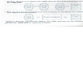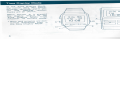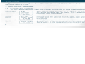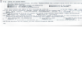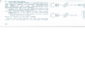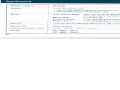
1
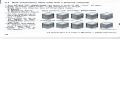
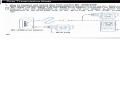
RC-4000/4400
HATTORI SEIKO CO., LTD.
TOKYO, JAPAN
INSTRUCTION MANUAL
© 1985 HATTORI SEIKO CO., LTD.
COS/87 Printed in Japan
Table of contents
Preface
Introduction to the RC-4000 Series .
Preface
3
3
. 6
Time Display Mode
. 7
1. How to set the time
. 7
2. How to set alarm on/off
Data Mode
8
1. Using the RC-4000/4400
8
1-1 Available data displayed
8
1-2 How to recall data
10
1-3 All clear function
11
1-4 How to input Memo Data
12
1-5 How to set Schedule Alarm . . . . 13
1 -6 How to set Weekly and
Daily Alarm
14
1-7 How to input Labels
15
1-8 How to change and add data. . . . 16
17
1-9 Alarm function
"^
2. Data input with a personal computer. . 17
2-1 Data construction
18
2-2
Character code table
19
Data Transmission Mode
20
1. How to transmit and receive data
from another RC-4000/4400
20
2. How to receive data from
a personal computer
22
3. How to transmit data to a personal
23
computer
4. Precautions for diita tr;msmiss,sion . . . 25
26
Trouble-shooting guide . .
Take proper care of your
RC-4000/4400
Accessories
1. Wrist plug
2. Connecting cable
3. Wrist adaptor
4. Bi-directional adaptor
Specifications
28
31
31
32
33
34
36
You have purchased one of the most advanced technological products available anywhere
today. This manual is designed so that you can derive maximum use and pleasure from the
SEIKO RC-4000 Series. Please follow the instructions carefully and enjoy this innovative
product for years to come.
Introduction to the RC-4000 Series
The SEIKO RC-4000 Series is a walking databank that stores a wide variety of your data and
also controls your schedule, in addition to the normal watch function. The data categories
are Memo Data, Schedule Alarm and Weekly Alarm. In the Memo Mode, you can input any
kind of data and they may be recalled individually. In the Schedule and Weekly Alarm Modes,
you will receive both a beep sound and a message — up to 12 characters — to remind you of
your schedule.
Features
"The SEIKO RC-4000 Series stores 80
separate pieces of information of 24
characters each (1920 characters at total).
* 2 types of unit model, the wrist type
RC-4000 and the pocket type RC-4400
are available.
*Data can be input on the RC-4000/4400
itself.
RC-4000
RC-4400
* Using an optional wrist adaptor RC-4300, data can be transferred between the two units of
RC-4000/4400.
i; 0,, MOK
,n
S9
ID'DB
1
Data can be input by means of a personal computer to the SEIKO RC-4000/4400 using a
wrist plug and connecting cable.
System Configuration
RC-4000/
4400
Bi-directional
adaptor
Wrist adaptor
Connecting cable
12-lid HON I
IQ'DB j
Personal computer
RC-4000/
4400
' Using an optional bi-directional adaptor RC-4200, data also can be transferred from the
SEIKO RC-4000/4400 to a personal computer.
Personal
computer
Time Display Mode
1. How to set the time
You can set the time by the following procedures:
In the Time Display Mode,
the month, date, day, hours,
minutes, seconds, alarm on/
off
and AM/PM symbol
marks are all shown.
When button A is pressed
the display reverts to the
Time Display Mode from
whatever its current mode.
* Hour and minutes are constantly displayed, even in
the Data Display Mode.
(1) Press button B while in the Time Display Mode to switch to the Time Setting Mode. At
first, seconds will start flashing.
(2) Press button C until the time element (e.g. seconds, minutes, hours, etc.) you wish to set
starts flashing. The time element changes in the following sequence.
1. Seconds —
- 6. Day of the Week
-— 2. Minutes
-
3. Hour (AM/PM)
4. Month -
5. Day -«-
(3) Press button E to advance the time element. Continuous pressing of button E rapidly
advances the time element. When the time element is set as desired, press C to advance to
next time element.
(4) When setting is complete, press button A to revert to the Time Display Mode.
2. How to set alarm on/off
When buttons D and E are pressed simultaneously, the
alarm on/off status alternates, as shown in the diagram.
To hear alarm beep sound, keep pressing buttons D and
E for 2 ~ 3 seconds.
"When the alarm on mark is not displayed in the Time
Display Mode, both the Schedule and Weekly Alarms
will not operate.
f^
f^
Display
4 —< No symbol
Alarm
ON
OFF
Data Mode
Data categories are Memo Data, Schedule Alarm and Weekly Alarm. Each category has an
individual label as a title.
1. Using the RC-4000/4400
1-1
Available data displayed
The RC-4000/4400 can input and display three kinds of Data types as shown below.
Memo Data
Schedule
Alarm
Weekly
Alarm
With the RC-4000/4400, you can input the
data of the following construction.
Memo Data: 3
(Memo 1, Memo
Schedule Alarm:
Weekly Alarm:
sets of 15 pages of data
2 and Memo 3)
1 set of 15 pages of data
1 set of 15 pages of data
Data Mode
Label
Number of Pages
Displayed that can be input
M1
15
Memo Mode
M2
15
M3
15
S.A Mode
S.A
15
W.A Mode
W.A
15
SEIKO
123-4567
ID.'DB
Each Memo Data consists of 2 rows of 12 characters each.
All kinds of data can be input (e.g., telephone numbers,
customer lists, timetables).
For easy sorting of data, you can put the
label for each data file group. For the method,
please refer to "How to input labels" on page
15.
MEETING
10-09p 2:03
ID.-DB
Your Schedule Alarm can be input with up to a 12 character
message and the desired month, date, hour and minute. At
designated time, the message will be displayed and the alarm
will sound.
The following diagram shows the data construction when the data is input on RC-4000/
4400 itself.
SUimiNB
•'ISflTfl 10:00
Your Weekly Alarm can be input with up to a 12 character
message and the desired day of the week, hour and minute.
Every week, at the designated time, the alarm will sound and
the message will be displayed.
ID'DB
1-2
How to recall data
1-3 All clear function
As mentioned in previous section, at the time of purchase, sample data has been input.
If buttons A, B and C are pressed simultaneously for more than 3 seconds the watch will be
set as follows:
At the time of purchase, the RC-4000/4400 has sample data with the following labels.
Sample data items
• M e m o l : TELEPHONE NUMBERS
• Memo 2: CLIENT LIST
• Memo 3: FLIGHT SCHEDULE
• SCHEDULE ALARM
I W E E K L Y ALARM
Time Display Mode: 1 2:00 AM, 0 seconds, Jan. 1, SUN., Alarm - off
uata ivioae. All aata labels and data items are all-cleared e
f
You can recall.the data in the following manner:
12-06 MDN 1 ©
TELEPHONE
59 I ^ NUMBERS
the •i| mi
( 1 ) In the Time Display Mode, press button C to recall1 the
first data label, "TELEPHONE NUMBERS" which
:h is
ID'DB \B
Memo 1.
ave bf»en input previously.
(2) Press buttons D and E to check the data fi
• Button D: reverse order
"Button E: forward
d
(3) Each time you press button C, a differen
splay ed in the following order. Continuous pressing of button C advances the labels automatically.
•natic ally.
— TELEPHONE NUMBERS
(Memo 1)
—- CLIENT LIST
(Memo 2)
WEEKLY ALARM — (4) Press button A to revert to the Time Display Mode.
10
12-06 non
Him
59
ID-'OB
A-q
fc^
C'
(.1
12-06 MON
•H Hti
59
1-01
' ^
ID'.DB
TELEPHONE
NUMBER
\
[
(3®O
t=>
nn
SUN
00
IE:DD
CLIENT
LIST
fFLIGHT
SCHEDULE
i?-06 non
^ r LIG 1 IT °CI ICDU LC
(Memo 3)
SCHEDULE ALARM
~\s in display
•Ira 59
ID:OB
1
0
A^
D-
M1
ezzic~3
0
M?
0
fnj
-E
11
When all data is cleared, the label will be displayed in the top left corner in the following
order: M1, M2, M3, S.A and W.A. For changing to your own title, refer to "How to Input
Labels."
You can input any desired data on your RC-4000/4400, by following the procedures
below. Be sure that all the data is cleared because the following procedures are for the allcleared status. When all the data is cleared, time setting must be done.
1-4 How to input Memo Data
Each data item is made up of 2 lines of 12 characters — 24 characters in all.
(1) Press button C to display the label Ml.
(2) Display the first blank page by pressing button E.
(3) The Data Input Mode is achieved by pressing button B. The first position in the upper
left corner will start flashing.
(4) Pressing button D or E will change character in the sequence shown below. When the
character you wish to set appears, press button C. To advance one space, simply press
button C.
C0-9
A~Z »
# $ % &
(
+
)
*
12
-
/
¥
=
-
7
3
(5) Continue inputting of data by repeating operation (4).
(6) When your data is input, press button B to lock the data.
(7) Scroll to the next blank page by pressing button E. Then repeat operations (3) and (4)
(8) Press button A to revert to the Time Display Mode.
1-5 How to set Schedule Alarm
(1) Press button C until "S.A" appears
S.H
on the display.
©
(2) Press button E to display the first
blank page.
ID:DB
(3) Press button B for setting mode —
the alarm symbol will start flashing.
Press button E to select alarm on/off.
(4) Press button C to start the first time element flashing.
* Even if the alarm symbol in the individual S.A Mode is
on, alarm will not operate if the alarm symbol in the
Time Display Mode is off.
* The setting location changes in the following sequence. A
r--Month
"-Day
"Hour (AM/PM)
•• Minute'
12 characters for the upper row message
13
* Month, day, hour and minute are set in exactly the same may as setting the time in
the Time Setting Mode with button E only.
* The 12 character message is set in the identical manner to the Memo Mode — button E
to advance and button D to return.
(5) When your desired character or digit appears, press button C to set.
(6) When your data is input, press button B to lock the data.
(7) Press button E to scroll to the next blank page. Repeat operations (3) to (7) to input data.
(8) Press button A to revert to the Time Display Mode.
1-6 How to set Weekly Alarm and Daily Alarm
(1) Press button C until "W.A" appears
on the display.
(2) Press button E to display the first
blank page.
(3) Press button B to switch to Data
Input Mode — alarm symbol will start
flashing. Press button E to select
alarm on/off.
* Even if the alarm symbol in the individual W.A Mode is
on, alarm will not operate if the alarm symbol in the
Time Display Mode is off. For details, refer to "Alarm
function".
14
' The setting location changes in the following sequence.
—— Day of the week —
—-— Hour (AM/PM)
- Minute
- - 1 2 characters for the upper row message
* Day, hour and minute are set in exactly the same way as for the Time Display Mode.
Selecting the blank location of the day of the week switches the Weekly Alarm to the
Daily Alarm Mode, meaning it will sound at the same time every day.
* The 1 2 character message is input in the identical manner to the Memo Mode — button
E to advance and button D to return.
* Pressing button D or E continuously speeds up the setting operation.
(4) Press button B to lock your data.
(5) Press button A to revert to the Time Display Mode.
1-7 How to input labels
As explained in "1-1 Available data displayed" on page 7, labels "M1, M2, M3, S.A,
W.A" can be changed to your desired title. The procedures are shown below.
(1) Press button C to display "M1".
(2) Then press button B to change to the Input Mode.
(3) With buttons D and E, you can write your own title over "M1", for example, "TELEPHONE NUMBERS". The manner is the same to the Memo Setting Mode.
(4) Press button B to lock.
(5) Press button A to revert to the Time Display Mode.
' ' " '•
15
1-8
1-9 Alarm function
How to change and add data
Data can be changed and added using character input and line delete functions.
(1) Display the data, you wish to edit by pressing buttons C, D and E.
(2) Press button B to change to the Data Input Mode.
(3) Data edit can be carried out in the following manner.
* To change data, press button C to select the character input location and choose the character
by pressing buttons D and E. When your desired
character appears, press button C to set.
* To add data, press button C to select the blank
location. Then press buttons D and E to choose the
character. When your desired character appears,
press button C to set.
* To delete data, repeat (1), (2) and press buttons
D and E at the same time. The entire row will
disappear.
(4) Press button B to lock.
Note: Line delete can be used only when Memo Mode
is displayed. In the Alarm Mode, characters can be
deleted but numerals cannot. Also the Labels cannot
be deleted.
16
12-06 tlOM
ilm S9
IDBB j
3-B
,C
g^g -E
123-4567
How to stop the alarm sounding
* The alarm will sound when the screen is in either the Time Display Mode or Data Mode.
You can stop the alarm sounding by pressing any button.
* When the alarm sounds the complementary data message will be displayed and will remain
after the alarm has stopped.
•When Schedule and Weekly Alarms are set for the same time the Schedule Alarm will
sound.
* If either the Schedule Alarm or Weekly Alarm have two settings for the same time, the
alarm to be set first will sound first.
Alarm symbol on/off
* Alarm symbols will appear in the
Time Display Mode and the
Schedule/Weekly Alarm Mode.
Alarms are operable only when
both of them are set to on.
Time Display
Mode: on
Time Display
Mode: off
Alarm Mode; on
Operates
Will not operate
Alarm Mode: off
Will not operate
Will not operate
2. Data input with a personal computer
When used with a personal computer, data can be transferred from the computer to the
RC-4000/4400. You can also change and add to the data on your RC-4000/4400. (Refer to
the previous sections for the operational procedure). In addition, you can set the data construction and the number of data labels as you desire.
17
2-1
Data construction when used with a personal computer
*The SEIKO RC-4000/4400 can store a total of 80 "lines" of data.
* Each of these "data lines" is 24 characters in length.
* Each data line may be one of three data types:
A Memo
A Schedule Alarm
Data construction with RC-4000/4400
A Weekly/Daily Alarm
* At the beginning of
each data type, there
is a "Label".
* There may be up to
12 labels in RC4000/4400 information file.
* Schedule and Weekly Alarms may have
only 1 label each.
•There may be as
many as 12 labels
for Memos.
7
0
sS
P S
P
1
1
A
Q A
2
2
B
R
B
Refer to your software's Instruction Manual
for specifications of data transfer.
0
D
E
F
P
8
P
A
a
A
Q
B
R
B
R
C
s
C
S
B
Q
0
~
Q
1
R
2
3
A
3
f
3
C
S
C
S
#
4
S
4
D
T
D
T
S 4
D T D T
%
&
E U E U
5
/o
5
E
U E U
6
&
6
F
V
F
V
7
7
G
w
G
w
8
( 8
H
X
H
X
9
)
I
Y
I
Y
A
B
12 characters x 2 rows x 80 data = 1920 characters.
18
Character code table
This table shows the characters which
can be input from a personal computer.
If the upper 4 bit codes — 0, 1, 8, 9 (not
shown on this table) are input, they will
be displayed as a space.
Upper 4-bit
2 3 4 5 6
2-2
9
*
+
J
Z
J
Z
K
• i[ K
•I
a
F V
F
V
7
G W G
w
(
8
H
X
H
X
)
9
I
Y
1
Y
*
+
J
Z
J
Z
K
•i
K
•i|
a
V
L
a
L
=
M
P
M P
N m N m
-
N
m N m
O
?
0
C
V
L
a
L
D
M
P
M P
E
- =
-
F
/
7
5
6
•
0
•
-
•
0
•
Data Transmission Mode
1. How to transmit and receive data from another RC-4000/4400
Data can be transmitted and received between different units of the RC-4000 and between
the RC-4000 and RC-4400. The RC-4300 wrist adaptor is necessary for data transmission.
(1) Connect your RC-4000/4400 to another via the wrist adaptor as shown below. (For
attachment of the wrist plug, refer to the "Wrist Plug" and "RC-4300" on pages 31 and
33).
* The arrow mark on the adaptor shows the direction
of transmission (see illustration). The data in A is to
be transferred to B. Make sure to connect correctly
to avoid mistransmission which may cause the data
to disappear.
(2) Switch both the receiving and transmitting RC4000s to "DATA IN (H)" mode by pressing
button A.
(3) Switch the transmitting RC-4000/4400 to "DATA
OUT (H)" mode by pressing button B, and transmission will start automatically after a beep sound*
has been heard from both units.
* At the end of transmission, there will be another beep and the display will automatically
revert to Time Display Mode. Simultaneously there will be a beep from the receiving
RC-4000/4400 which will then display the first data label transmitted.
-HiDl
RC-4300 wrist adaptor
20
* Be sure that transfer is carried out correctly. If not, previous data in the reception RC4000/4400 may be erased or the reception RC-4000/4400 may be all cleared.
* After transmission, the data in both RC-4000/4400s will be identical.
21
2. How to receive data from a personal computer
(1) Connect the RC-4000/4400 to a personal computer using a wrist
plug and connecting cable as shown below (for attachment of the
wrist plug, refer to "Wrist Plug" and "Connecting Cable" on pages
31 and 32).
(4) When data transfer is carried out, another beep sound is heard and RC-4000/4400 display
shows the first label transferred.
Refer to your software's Instruction Manual for details.
3. How to transmit data to a personal computer
(1) Connect your personal computer to the bi-directional
adaptor and the RC-4000/4400 to the adaptor, as
shown in the illustration below. (For attachment refer
to "Bi-directional Adaptor" on page 34.) Press button A
to change the display to "DATA IN (H)" or "DATA IN
(L)".
Connecting cable
(2) Switch the RC-4000/4400 to "DATA IN (H)" or
"DATA IN (L)" by pressing button A. (H and L show
transfer speed. Refer to "Precautions for Data Transmission Mode".)
(3) When signal is input from your personal computer, a
beep sound is heard and the data transfer automatically starts.
22
12-06 MDN
•< m
59
IQ:DB
DRTR IN (H)
Bi-directional adaptor
23
(2) Switch over to "DATA OUT (H)" or "DATA OUT
(L)" to start transmission by pressing button B. Refer
to "Precautions for Data Transmission Mode".
(3) A beep sound is heard as soon as the transmission
starts.
(4) When the transmission is completed, another beep
sound is heard and the display reverts to the Time
Display Mode.
Notes on Data Transfer with a personal computer
* Be sure that transfer is carried out correctly. If not, previous data in the reception RC4000/4400 may be erased or the reception RC-4000/4400 may be all cleared.
* The procedures shown herein are different according to the personal computer and the
software used. For details, refer to your software's Instruction Manual.
4. Precautions for Data Transmission Mode
(1) Before starting data transmission, make sure that all the connections are correctly made.
(21 During data transmission, avoid touching the buttons or cables which may cause a mistransmission or. erase data.
(3) There are two transfer speeds — High (H), which transfers the information in 10 seconds,
and Low (L) with a transfer speed of 80 seconds. One push of button A in the Time
Display Mode will change the display to "DATA IN (H)"; one more push changes it to
"DATA IN (L)". Both the reception and transmission should be set at the same speed.
DflTfl IN (L)
©,
Data input erases previous data
As soon as data transfer starts, the previous data is erased as the new data is input. Also, if
data transfer fails, previous data is erased. If display reverts to the Time Display Mode while
in "DATA IN (H)" mode, data will not be erased.
* Before switching to "DATA OUT (H)" mode, make sure that all the necessary connections
have been completed.
* All the data will be erased when the battery is exhausted.
24
25
Trouble-shooting guide
Problem
Possible Cause
Solution
There is a starting
beep but the RC4000/4400 is still
1. The personal computer stopped in the
middle of transfer due to power cut-off or
other reasons.
If you find the error.
try the data transfer
again.
after 10 sec or
in"l"mort"«
af er 80 sec.
^'
*Th s should be done
DRTR IN
(H)
The Connectin 9
cable was disconnected
dunng transfer.
3. The RC-4000/4400 was ready to receive
data but the personal computer was not
fully ready to transmit. Therefore any
input is in error.
4. Errors in software that you have written
or rewritten yourself.
DflTfl IN
(L)
5. Transmitting and receiving speed not the
same: e.g. when the RC-4000/4400 is
set to "L" and the computer transmission
speed is 2,400 BPS.
only after pressing
button A to reve rt
to the Time Disc lay
Mode. Before re
turning to the T me
Display Mode, tr e
display will be as in
the
for 4 ~ 5 sec.
Possible Cause
Problem
The connecting cable is not properly attached.
(If the RC-4000/4400 is worn often, care
should be taken to keep the connection on it
free from dirt.)
Check cable connections and try
the transfer again.
A : ter receiving
diita, there is the
fc Mowing display.
1. There was an error in the data prepared on
the personal computer: e.g. a symbol is
entered where a numeral is obligatory.
Check data in personal computer.
2. Transmission was carried out with no data
input to the personal computer.
*Be careful when
writing new software yourself.
'
"|
IZ:DD
'
IE:DD \6
Solution
T nere is no
st arting beep
or d no data
is transferred.
All the displays
become dark.
3. Transmitting and receiving speed not the
same — The RC-4000 is set to "H" but
the computer transmission speed is 300
BPS.
This is not an error.
Press button A or
B to revert to the
normal condition.
27
Take Proper Care of Your RC-4000/4400
1) Water/Perspiration
Your RC-4400 is not water resistant; care should be taken not to expose it to water or
heavy perspiration. If it becomes wet wipe it completely with a dry cloth.
Do not operate any of the buttons when the watch is wet.
The crystal may become fogged if the outside temperature is lower than that inside the
RC-4000/4400. A temporary fogging will not cause a malfunction, but if it does not
clear, consult your dealer.
2) Temperature
Your RC-4000/4400 is preadjusted to function accurately when worn on the wrist at a
normal temperature range (14°F to 140°F or -10°C to +60°C).
* A small amount of time loss/gain may occur.
" The display may change more slowly.
The watch will, however, return to normal when the temperature rises.
3) Shocks
Be careful not to drop the RC-4000/4400 or slam it against a hard surface.
4) Battery
Your RC-4000/4400 uses one SB-T12 (BR2325) lithium battery. A new battery will
serve for about two years. This two-year battery lifetime is calculated on the basis of the
following conditions.
* Button operations — maximum of 20 times a day
* Use of alarm — maximum of 3 times a day, beeping for 20 seconds
Extremely high temperatures
Care should be taken not to expose your watch to high temperatures (over 140°F or
60° C).
Keep it away from direct sunlight or hot locations. If left in excessive heat:
•The digital display may become black, but this condition will disappear without aftereffects when the temperature returns to normal.
* The battery life may be shortened, and the battery may suffer electrolyte leakage.
Note: Letting the battery run down or replacing the battery will destroy all data
stored in the RC-4000/4400. The RC-4000/4400 is not equipped with a run-down
battery warning (BLD) capability.
For replacing battery, consult your dealer.
Extremely low temperatures
The watch will work accurately down to 14° F (-10°C), but do not leave it in a cold place.
If exposed to excessive cold for a long time:
28
29
5) For your convenience
* To adjust the wrist band, ask your dealer.
* RC-4400 can have a plaque on its back for an engraving (e.g., your initials).
Accessories
1. Wrist plug (TP-400)
When connecting the RC-4000 to connecting cable, RC-4200, RC-4300 or a personal
computer, a special wrist plug is attached (it is not required for the RC-4400).
How to attach and detach from RC-4000
First, the signal pin on the wrist plug is matched up with the signal terminal on the left
side of the RC-4000 which is then pushed into position from the right side.
For attaching the wrist plug:
1) Fix left side.
For detaching:
1) Press on the right side.
^2=-
2) Finish attachment by pushing from
the right side.
30
2) and remove the RC-4000
Be careful not to exert too much force on the wrist plug. Never remove from the left side
or damage may result.
31
2. Connecting cable
The RC-4000/4400 is connected to a
personal computer using a special connecting cable. There are cables available for
the Apple II, II+, lie. Me, Commodore
64, IBM-PC, and most compatibles. For
details, please ask your dealer.
(1) Insert the jack on connecting cable into
socket in wrist plug. When connecting
hold the wrist plug firmly.
(2) To disconnect, again hold the wrist
plug firmly. Take hold of jack plug and
remove.
* Do not pull on the cable as this could
break the wire inside.
How to attach to the RC-4400
Insert the jack plug on the connecting
cable into the socket in the pocket model.
32
3. Wrist adaptor (RC-4300)
The wrist adaptor is used when data is transmitted to other RC-4000/4400. For the
method of data transmission refer to "How to transmit and receive data from another RC4000/4400" on page 20.
RC-4300
How to connect to RC-4000
(1) Insert the jack plug on the wrist adaptor into the socket on the wrist plug. (The wrist plug
is unnecessary for the RC-4400.)
(2) To disconnect, grip the jack plug firmly on the receiving RC-4000 side and the adaptor
on the transmission RC-4000 side. Do not disconnect by pulling on the cable as this could
break the wire inside.
To disconnect the RC-4000 from the wrist plug, refer to "Wrist plug" on page 31.
Note: Take care to avoid contact of the 2 jack plugs on the wrist adaptor as this will cause
shorting of the battery.
33
4. Bi-directional adaptor (RC-4200)
This adaptor is used when data is transmitted from the RC-4000/4400 to a personal
computer. For the method of data transmission — refer to "How to transmit data to
personal computer" on page 23.
1. PC 1 jack: connecting cable is inserted
when used with a personal computer
with RS232C signal.
2. PC 2 j a c k : connecting cable plug is
inserted when used with a personal computer with other than RS232C signal.
3. LED: lights up when the power switch
is set to ON.
4. RC IN/OUT selector switch: set to RC OUT when data is transmitted from the RC4000/4400 to a personal computer, and RC IN, when data is transmitted to the
RC-4000/4400 from a personal computer.
(1) Connection of the bi-directional adaptor to personal computer.
Insert the connecting cable plug into the PC1 or PC2 jack.
(2) Connection of the bi-directional adaptor to the RC-4000.
Insert the jack plug on the bi-directional adaptor into the socket on the wrist plug.
Battery replacement
1. RC-4300 wrist adaptor
(1) Remove the 2 screws on the bottom cover with a Phillips
head screwdriver.
(2) Take off bottom cover and detach bactery. Care should
be taken not to pull too strongly on the snap connector
lead as the jack plug and cable will become detached.
(3) Attach snap connector to new battery.
(4) Replace bottom cover and use screwdriver to replace
2 screws.
2. RC-4200 bi-directional adaptor
(1) Remove battery cover.
(2) Detach batteries.
(3) Insert new batteries. (Manganese dry battery S-006P 9V)
Note: If the bi-directional adaptor is not going to be used
for some time we recommend removing the batteries as
there may be leakage.
35
34
Specifications
Memory capacity:
2K RAM
Display:
3-line dot matrix LCD
— time of day always displayed on bottom line
— data displayed on 2 12-character lines
Modes:
Time Display Mode:
Memo Mode:
Schedule Alarm:
Weekly Alarm:
36
Year, month, date, AM/PM, day of
the week, hours, minutes, seconds
2-line message
1-line message/alarm time & date
1-line message/alarm time & day
Battery:
1 lithium battery BR2325 (Matsushita, SB-T12)
Battery life:
About 2 years
Operational temp, range:
14°F ~ 140°F (-10°C ~ +60°C)
Casing:
RC-4000 - Metal
RC-4400 - Plastic
Water resistance:
RC-4000 — Water Resistant
RC-4400 — Non-Water Resistant
Data transmission:
RS-232C Serial (2400/300 Baud)
External dimensions:
RC-4000 - 39.8 x 33.5 x 9.9mm
Weight: 38.09 approx. (excluding strap)
RC-4400 - 67.0 x 28.4 x 1 1.2mm
Weight: 60. Og approx. (excluding leather case)
Designs and specifications are subject to change without notice.
37
MEMO