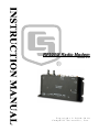
1
RF500M Radio Modem
Revision: 8/10
C o p y r i g h t © 2 0 0 8 - 2 0 1 0
C a m p b e l l S c i e n t i f i c , I n c .
Warranty and Assistance
The RF500M RADIO MODEM is warranted by Campbell Scientific, Inc. to
be free from defects in materials and workmanship under normal use and
service for twelve (12) months from date of shipment unless specified
otherwise. Batteries have no warranty. Campbell Scientific, Inc.'s obligation
under this warranty is limited to repairing or replacing (at Campbell Scientific,
Inc.'s option) defective products. The customer shall assume all costs of
removing, reinstalling, and shipping defective products to Campbell Scientific,
Inc. Campbell Scientific, Inc. will return such products by surface carrier
prepaid. This warranty shall not apply to any Campbell Scientific, Inc.
products which have been subjected to modification, misuse, neglect, accidents
of nature, or shipping damage. This warranty is in lieu of all other warranties,
expressed or implied, including warranties of merchantability or fitness for a
particular purpose. Campbell Scientific, Inc. is not liable for special, indirect,
incidental, or consequential damages.
Products may not be returned without prior authorization. The following
contact information is for US and International customers residing in countries
served by Campbell Scientific, Inc. directly. Affiliate companies handle
repairs for customers within their territories. Please visit
www.campbellsci.com to determine which Campbell Scientific company
serves your country.
To obtain a Returned Materials Authorization (RMA), contact Campbell
Scientific, Inc., phone (435) 753-2342. After an applications engineer
determines the nature of the problem, an RMA number will be issued. Please
write this number clearly on the outside of the shipping container. Campbell
Scientific's shipping address is:
CAMPBELL SCIENTIFIC, INC.
RMA#_____
815 West 1800 North
Logan, Utah 84321-1784
For all returns, the customer must fill out a “Declaration of Hazardous Material
and Decontamination” form and comply with the requirements specified in it.
The form is available from our website at www.campbellsci.com/repair. A
completed form must be either emailed to [email protected] or faxed to
435-750-9579. Campbell Scientific will not process any returns until we
receive this form. If the form is not received within three days of product
receipt or is incomplete, the product will be returned to the customer at the
customer’s expense. Campbell Scientific reserves the right to refuse service on
products that were exposed to contaminants that may cause health or safety
concerns for our employees.
RF500M Table of Contents
PDF viewers note: These page numbers refer to the printed version of this document. Use
the Adobe Acrobat® bookmarks tab for links to specific sections.
1. General Radiotelemetry Network ...............................1
1.1
1.2
1.3
1.4
Introduction ..............................................................................................1
Field Station..............................................................................................1
Base Station ..............................................................................................2
Repeater ....................................................................................................2
2. Radiotelemetry Network Components....................2-1
2.1 RF500M Modem ......................................................................................1
2.1.1 Physical Description .......................................................................1
2.1.1.1 Specifications ........................................................................2
2.1.2 RF500M States................................................................................2
2.1.3 Setting the RF Address ...................................................................2
2.1.4 RF500M Modem Lights .................................................................2
2.1.5 RF500M Connections .....................................................................3
2.2 RF500M Compatible Radios ....................................................................3
2.2.1 Analog Radio Description...............................................................3
2.2.3 Digital Radio Description ...............................................................5
2.3 Antennas and Cables ................................................................................5
2.3.1 Antenna Mounts..............................................................................5
2.3.2 Antenna Orientation........................................................................5
2.3.3 Antenna Cables and Connectors .....................................................6
2.4 Tripods, Towers, Enclosures, and Power Supplies...................................8
2.4.1 Tripods and Towers for Mounting..................................................8
2.4.2 Enclosures.......................................................................................8
2.4.3 Power Supply..................................................................................8
2.4.3.1 Lead Acid Batteries ...............................................................8
3. Assembling the Radiotelemetry Network ...............3-1
3.1 Final Layout..............................................................................................1
3.2 Configure the RF500M.............................................................................1
3.2.1 Device Configuration Utility ..........................................................1
3.2.2 Install Base Station .........................................................................3
3.2.3 Install Nearest Repeater/Field Station.............................................3
3.3 LoggerNet Setup.......................................................................................4
3.4 Test the Radiotelemetry Link ...................................................................4
3.4.1 A Successful Test............................................................................5
3.4.2 An Unsuccessful Test .....................................................................5
3.5 Troubleshooting Unsuccessful Communication Attempts .......................5
3.5.1 Troubleshooting the Physical Link Between Base and Field Station
..................................................................................................................5
i
RF500M Table of Contents
4. Operation of the Radiotelemetry Network ............. 4-1
4.1 Monitoring and Collecting Data with LoggerNet .................................... 1
4.1.1 Basic Concepts ............................................................................... 1
4.1.2 Using the LoggerNet Setup Screen ................................................ 1
4.1.3 Automated Data Collection with LoggerNet.................................. 2
4.1.4 General Communication – LoggerNet Connect Screen ................. 3
4.2 Datalogger Initiated Communications ..................................................... 4
4.2.1 – One Way Data – RF500M network.............................................. 4
Appendices
A. Fundamentals of Radiotelemetry........................... A-1
A.1
A.2
A.3
A.4
Radio Waves ........................................................................................... 1
Antennas ................................................................................................. 2
RF500M Modem..................................................................................... 2
Transceiver.............................................................................................. 3
Appendix B. Power Calculations ................................ B-1
Glossary
Figures
2-1. RF500M Modem ................................................................................. 2-1
2-2. RF500M Radio Jumper Location ......................................................... 2-4
2-3. RF500M Radio Jumper Expanded View ............................................. 2-5
2-4. The PD237 Crossover Plate Antenna Mount....................................... 2-6
2-5. The PD46 Clamp Mount...................................................................... 2-7
2-6. Type-NM (male), BNC, and Type-NF (female) Connectors............... 2-7
4-1. LoggerNet Main Tool Bar ................................................................... 4-1
4-2. LoggerNet Setup Screen - Schedule Tab............................................. 4-3
4-3. LoggerNet Connect Screen.................................................................. 4-4
Tables
2-1. RF500M CS I/O to Datalogger Connector Description....................... 2-3
2-2. Common Antennas and Characteristics ............................................... 2-7
ii
Section 1. General Radiotelemetry
Network
1.1 Introduction
Data retrieval from a remote site can be difficult. One method to accomplish
data collection from isolated sites is through a radio telemetry (RF telemetry)
network. Dataloggers can be accessed by RF telemetry, which requires no
physical connection from the computer to the datalogger. The RF telemetry
link reduces the number of visits to a remote site for data collection.
The RF telemetry network is designed for complete computer control.
LoggerNet software allows data collection from the datalogger, transmitting
datalogger programs, and displaying current readings from the datalogger.
The requirements specific to a RF telemetry network include:
•
The distance between radio stations should not be greater than
approximately 25 miles.
•
The stations should not have major obstacles between them; therefore,
they should be within line-of-sight of each other.
Telemetry network’s three basic components are:
•
Field Station
•
Base Station
•
Repeater Station
This manual covers the use of the RF500M Modem. Some LoggerNet
software topics are also addressed.
1.2 Field Station
Purpose:
The field station is where the measurements are made. The
Campbell Scientific datalogger resides at this station taking the
desired measurements. Any field station can also operate as a
repeater. The only requirement is that the station’s antenna must
be able to communicate in all desired directions. This may require
an omnidirectional antenna.
Equipment Required:
•
Radio
•
RF Modem
•
Antenna and antenna cable
•
Datalogger
•
Power supply, enclosure, sensors, and mounting needs
1-1
Section 1. General Radiotelemetry Network
1.3 Base Station
Purpose:
A base station utilizes a computer to collect data from the field
station(s). Normally, all communication to the field stations
originate at the base station. Data retrieval, remote programming,
and system analysis can all be done from the base station.
Equipment Required:
•
Radio
•
RF Base Station
•
Computer with LoggerNet software
•
Antenna and antenna cable
•
AC power
1.4 Repeater
Purpose:
To act as relay between two communicating stations separated by
too long of a distance or an obstacle which impedes direct
communication. A repeater is not always required in an RF
telemetry network. A field station can also function as a repeater.
Equipment Required:
1-2
•
Radio
•
RF Modem
•
Antenna and antenna cable
•
Power supply, enclosure and other mounting needs
Section 2. Radiotelemetry Network
Components
2.1 RF500M Modem
The RF500M is an interface between the computer and the radio when used at
a base station, and an interface between the radio and the datalogger at a field
station. In a repeater station, the RF500M is an interface between two other
communication stations. The RF500M is an RF modem. LoggerNet will refer
to the RF500M as an RFBase-TD or RFRemote-PB.
2.1.1 Physical Description
There are three ports for interfacing external devices on the front of the
RF500M. The port labeled Transceiver connects to the radio (RF310 series,
RF300 series, or DataRadio DL-3400), the port labeled CS I/O connects to
either the datalogger or to the PC as an RF Base, and the port labeled RS-232
connects to an RS-232 radio or the PC as an RF Base.
FIGURE 2-1. RF500M Modem
2-1
Section 2. Radiotelemetry Network Components
The light located between the Transceiver port and the RS-232 port is used
primarily to indicate when the radio is transmitting and receiving by blinking
red and green. The light located between the RS-232 and CS I/O ports is used
primarily to indicate when data is transmitted between the datalogger and
RF500M modem by blinking red and green.
2.1.1.1 Specifications
Power
Voltage:
Current:
7 to 20 Vdc
Active:
<15 mA
Quiescent: <350 μA
Physical
Dimensions: 6 5/16” x 3 11/16” x 7/8”
160 x 95 x 22 mm
Weight:
.4 lb
.18 kg
2.1.2 RF500M States
The RF500M modem can operate in several different states depending on the
configuration applied using Device Configuration Utility. The RF500M CS
I/O port can be utilized in either the datalogger communication SDC
(Synchronous Device Communication) state with SDC address 7, 8, 10, or 11
or in the PC to RF base state. The RS-232 port can be used in either the PC to
RF base state, the RS-232 digital radio connection state, or the RF500M to
datalogger state. The proper state must be determined and configured before
deploying the RF500M in the field. Device Configuration Utility is used to
change and apply the settings for the RF500M.
2.1.3 Setting the RF Address
Each RF500M, including the one used as the RF base, must have a unique RF
Address or RF ID. The RF ID is similar to a phone number. This unique
identifier allows the base station to communicate with a specific field station.
The RF ID can be any number from 1 to 255 and is set using Device
Configuration Utility. The RF500M is shipped with a default RF ID of 1.
NOTE
When using a phone to RF configuration, the RF500M RF ID
must be set to 255.
2.1.4 RF500M Modem Lights
The two lights on the front panel of the RF500M have several purposes. The
primary function of the lights is to indicate when data is being received or
transmitted from both the radio and the datalogger.
2-2
Section 2. Radiotelemetry Network Components
The lights can also be used to verify the appropriate power up sequence of the
RF500M. View the indicator lights while applying power with the power
adapter or connecting the datalogger to the RF500M CS I/O Port with an SC12
cable. The sequence of the lights flashing after connection indicates the power
up self-test status. Both lights should cycle through a combination of colors
and then turn off to indicate the RF500M has powered up correctly and is
ready for operation.
2.1.5 RF500M Connections
The CS I/O port is normally used to connect the RF500M to the datalogger
with an SC12 cable. Table 2-1 describes the 9-pin connections. A null modem
cable with female end connectors (CSI Part Number: 13657) is used to connect
the RS-232 port of the RF500M to the PC. The 10-pin rectangular connector
is for connection to the transceiver interface.
TABLE 2-1. RF500M CS I/O to Datalogger Connector
Description
Pin
Description
1
+5 V: Not Used
2
GND: Ground
3
Ring: Ring to Datalogger
4
RXD: Transmit from RF500M
5
ME: Modem Enable from Datalogger
6
SDE: Synchronous Device Enable
7
CLK/HS: Clock/Handshake from Datalogger
8
+12V: Supply from External Source
9
TXD: Received by RF500M
2.2 RF500M Compatible Radios
2.2.1 Analog Radio Description
The RF500M is compatible with the following analog radios: RF310 series,
RF300 series, and unmodified DataRadio DL-3400 radios.
The radios are connected to the RF modem by a special radio cable. The 9-pin
connector has a red and black wire coming out of the connector. The 9-pin
connector should be connected to the radio. The red and black power wires
should be connected to 12V and Ground respectfully. The 10-pin connector
should be connected to the RF modem.
2-3
Section 2. Radiotelemetry Network Components
Depending on the radio being used, the appropriate internal jumper must be
selected on the RF500M circuit board. There is a set of six jumpers in series
located just under the Campbell Scientific, Inc. name and circuit board version
number etched on the board. When looking at the front panel with the three
ports, the jumpers that need to be set are located in the back, right corner of the
circuit board. The two jumpers next to the edge of the circuit board should be
selected if using the RF310 series radios. The two jumpers in the center
should be selected if using the RF300 series radios. The two jumpers on the
inside of the board should be selected if using an unmodified DataRadio DL3400 radio.
FIGURE 2-2. RF500M Radio Jumper Location
2-4
Section 2. Radiotelemetry Network Components
FIGURE 2-3. RF500M Radio Jumper Expanded View
2.2.3 Digital Radio Description
The RF500M is compatible with digital RS-232 radios such as the DataRadio
Integra radio.
The digital radios are connected to the RF500M modem with a serial cable
between RS-232 ports. Use Device Configuration Utility to configure the
RS-232 connection options in the RF500M to work with the digital radio.
2.3 Antennas and Cables
Antennas radiate and receive the radio signals. Each radio in an RF telemetry
system must have an antenna. Coaxial cable is used to connect the antenna to
the radio.
2.3.1 Antenna Mounts
Antennas must be mounted above any surrounding buildings or obstacles.
Antennas must be properly oriented in relationship to the other antennas for RF
communications to work. Antennas have various mounting options. Specific
questions regarding antennas can be directed to Campbell Scientific, Inc.
2.3.2 Antenna Orientation
Antennas must be oriented correctly to allow communication between RF sites.
First determine if your antenna is omnidirectional or unidirectional.
2-5
Section 2. Radiotelemetry Network Components
An omnidirectional antenna will transmit/ receive in a full 360 degree circle.
Generally, an omnidirectional antenna will be a straight cylindrical rod which
is to be mounted vertically at the top of a tripod.
A unidirectional antenna is designed to transmit/receive in a particular
direction, or in a specified sector. There are various shapes of unidirectional
antennas. The most common is the Yagi antenna. The elements of a Yagi
antenna can be mounted either vertically or horizontally, corresponding to
either vertical or horizontal polarization.
FIGURE 2-4. The PD237 Crossover Plate Antenna Mount
Normally, all antennas will be mounted with vertical polarization. Whichever
polarization is used, be sure to keep antennas at all sites identically polarized.
2.3.3 Antenna Cables and Connectors
The most common cable type to connect a radio to the antenna is a coaxial RG8A/U cable. Two connectors are required for each length of cable. The
connector for the radio is a BNC type connector. The connector for the
antenna is usually either a Type-NM or Type-NF. The BNC, Type-NM, and
Type-NF connectors are shown in Figure 2-6. The Type-NM (male) connector
is for antennas with a female receptacle, and Type-NF (female) for antennas
with male receptacles.
A Campbell Scientific antenna cable complete with connectors is specified as
either COAX NM-L or COAX NF-L. COAX NF-L is a coaxial RG-8A/U
cable with a BNC connector on one end and a Type-NF connector on the other.
See Table 2-2 for cable requirements for common antennas.
Due to power loss through the cable, the length of coax cable cannot be
extended to any desired length. The amount of power loss is dependent on the
radio frequency. RG-8A/U will lose approximately 3.1 dB/100 ft. at 200 MHz
and 5.0 dB/100 ft. at 400 MHz. Power loss calculations are reviewed in
Appendix B.
2-6
Section 2. Radiotelemetry Network Components
FIGURE 2-5. The PD46 Clamp Mount
FIGURE 2-6. Type-NM (male), BNC, and Type-NF (female)
Connectors
TABLE 2-2. Common Antennas and Characteristics
Antenna
BA1010
BA1012
BA1312
BA6012
BA6110
BA6312
PD200
PD201
PD220
PD344
PD390S
PD400
PD688S
PD1107
PD1121
Type
Omni
Omni
Omni
Omni
Omni
Omni
Omni
Omni
Omni
Dipole
Yagi
Omni
Yagi
Omni
Dipole
VHF or
UHF
VHF
VHF
VHF
UHF
UHF
UHF
VHF
UHF
VHF
VHF
VHF
VHF
UHF
VHF
VHF
Cable
Coax NM-L
Coax NM-L
Coax NM-L
Coax NM-L
Coax NM-L
Coax NM-L
Coax NF-L
Coax NF-L
Coax NF-L
Coax NF-L
Coax NF-L
Coax NM-L
Coax NF-L
Coax NF-L
Coax NF-L
Gain(dB)
Unity
Unity
3.0
Unity
Unity
3.0
5.8
5.0
5.25
4.5
8.0
7.5
10.0
3.0
3.0
Pipe O.D.
3/4" - 2 1/8"
1" - 2 1/4"
1" - 2 1/4"
1" - 2 1/4"
3/4" - 2 1/8"
1" - 2 1/4"
1" - 2 3/4"
1" - 2 3/4"
1" - 2 3/4"
2 1/2"
1 5/16, 2 1/4, or 2 3/8
1" - 2 3/4"
1 5/16" - 2 1/4"
1" - 2 3/4"
2 1/2"
Mounting
Type
U-Bolts
U-Bolts
U-Bolts
U-Bolts
U-Bolts
U-Bolts
PD46 (Fig 2-5)
PD46 (Fig 2-5)
PD46 (Fig 2-5)
Clamps
PD37 (Fig 2-4)
PD46 (Fig 2-5)
U-Bolts
PD46 (Fig 2-5)
Clamps
2-7
Section 2. Radiotelemetry Network Components
2.4 Tripods, Towers, Enclosures, and Power
Supplies
There are several methods of mounting and housing sensors and other
equipment for a station.
2.4.1 Tripods and Towers for Mounting
For the different mounting requirements, Campbell Scientific offers many
styles and sizes of tripods and towers. All mounting options available from
Campbell Scientific are rugged instrument mounts that provide sturdy support
for Campbell Scientific sensors, enclosures, and measurement electronics.
2.4.2 Enclosures
Enclosures are needed to keep water and debris from damaging the data
acquisition equipment. Campbell Scientific, Inc. enclosures are designated as
“rain-tight,” and are designed to mount to a tripod or tower.
The fiberglass enclosures are classified as NEMA 4X (water-tight, dust-tight,
corrosion-resistant, indoor and outdoor use). A 1.25” diameter entry/exit port
is located at the bottom of the enclosure for routing cables and wires. The
enclosure door can be fastened with the clasp for easy access. The enclosure’s
clasp door can be secured with a basic lock. Both enclosures are white for
reflecting solar radiation, reducing the internal temperature.
The model ENC12/14 fiberglass enclosure has inside dimensions of 14" x 12"
x 5.5”, the model ENC14/16 fiberglass enclosure has inside dimensions of 14"
x 16" x 5.5" and the model ENC16/18 fiberglass enclosure has inside
dimensions of 16" x 18” x 8.5".
2.4.3 Power Supply
A radiotelemetry network requires a reliable power supply at each station. A
solar panel or 110/220 VAC charging source is normally required due to the
large current drain of the radio.
2.4.3.1 Lead Acid Batteries
Lead acid batteries are designed to be float charged by a solar panel or AC
power source. The role of the lead acid battery is to supply power when the
charging source is absent, e.g., in case of power failures (AC charging), or
during times of zero charge with a solar panel. Generally, we recommend a
minimum of 7 Amp-hour batteries for RF applications.
2-8
Section 3. Assembling the
Radiotelemetry Network
This section provides a logical order for RF network assembly and deployment. Details of
specific components in the system are described in Section 2 “Radiotelemetry Network
Components.” Section 2 is cross-referenced throughout this assembly section.
3.1 Final Layout
The initial locations of the base, field, and repeater stations have likely been
determined already. Locate RF stations on an area map, preferably a
topographic map. Draw a line along every communication path. Each field
station must have a path connecting it back to the base station. No path can be
going through a mountain or large obstacle; this would negate the line-of-sight
requirement. A station may need to be moved or a repeater station may need to
be added if this requirement is not met.
At each station there is an RF modem. Each modem requires a unique ID
number (RF ID). A valid RF ID is a number with the range of 1 to 255. On
the map, label the base station and the remaining stations with different ID
numbers. Later, each modem will be set with the corresponding ID number.
The RF ID, similar to a phone number, allows the base station to call many
different field stations.
3.2 Configure the RF500M
3.2.1 Device Configuration Utility
Device Configuration Utility software is used to configure the RF500M
modem. Device Configuration Utility is included with LoggerNet or it can be
downloaded for free from the Campbell Scientific web site
(http://www.campbellsci.com). The configuration options can be seen in the
following figure:
3-1
Section 3. Assembling the Radiotelemetry Network
To configure the RF500M, apply power to the modem, wait for the power-up
sequence lights to cycle and then turn off, connect the PC to the RF500M RS232 port with a null modem cable, open Device Configuration Utility,
highlight the RF500M option in the Device Type list, and click Connect. Press
the green configuration button on the RF500M either before or while
connected to enable the settings in Device Configuration Utility.
There are five configuration options for the RF500M
3-2
1.
RF ID – Set the modem address with a value from 1-255. Each RF500M
in the network must have a unique RF ID.
2.
CS I/O Settings – Set the CS I/O interface options. Choose the SDC
address that will be used to communicate with the datalogger or if a digital
radio is attached and this RF500M is used as an RF Base, select the
Connected to PC via SC532 option (requires an SC532(A) between the CS
I/O interface and the serial port of the PC). If using the Connected to PC
via SC532 option, make sure the RS-232 interface is not set as Connected
to PC. If using the CS I/O interface to connect a datalogger, make sure the
RS-232 interface is not set as a PakBus datalogger.
3.
RS-232 Settings – Set the RS-232 interface options. Choose whether the
RF500M will be connected to the PC with a null modem cable, if a digital
radio will be connected to the RS-232 interface, or it will be connected to
a datalogger. If using the Connected to PC option, make sure the CS I/O
is not set as Connected to PC via SC532.
Section 3. Assembling the Radiotelemetry Network
4.
Baud Rate – Set the baud rate for the RS-232 interface.
5.
Sleep-Mode Enabled – Determine if sleep mode functionality will be
enabled for RF300 series radios. In all other cases, this setting will be
ignored.
Once the RF500M has been configured, it is ready to be deployed.
3.2.2 Install Base Station
When the RF500M is used in a base station configuration, the PC is attached to
the RS-232 port with a null modem cable. If a digital radio is being used on
the RS-232 port, the CS I/O port can be configured to communicate with the
PC but an SC532(A) and serial cable must be used between the PC and the CS
I/O port of the RF500M.
1.
CAUTION
Connect the RF500M to 12 V and ground. Connect the radio to 12 V,
ground, and the RF Modem (RF500M).
Radio transmission without an antenna connected can
damage the radio.
2.
Mount the base station antenna in a location that is higher than any
surrounding buildings or obstacles. Refer to Section 2.3 for more
information on mounting the antenna.
3.
After the antenna is mounted, connect the coax cable between the antenna
and radio.
4.
Connect a large gauge (approximately 8 AWG) copper wire from the
antenna to a good earth ground. This is for lightning protection. This is
required for any antenna, especially if the coax cable from the antenna
goes inside a building.
5.
Connect a null modem cable from the computer serial port to the RS-232
port of the RF500M. If a digital radio is being used on the RS-232 port,
an SC532 and serial cable can be used between the PC and the CS I/O port
of the RF500M. Set the appropriate configuration options in the RF500M
with Device Configuration Utility depending on the port connected to the
PC.
3.2.3 Install Nearest Repeater/Field Station
Now install the nearest field station. If it communicates with the base station
via a repeater, the repeater station must also be installed. Make sure the correct
RF ID has been configured in the RF500M that is being deployed in the remote
field station or repeater location.
3-3
Section 3. Assembling the Radiotelemetry Network
Following is the order in which a general RF field station should be installed.
A repeater station is installed in the same order.
1.
Tripod or tower
2.
Enclosure and datalogger
3.
Antenna - Orient correctly; remember direction and polarization
4.
Solar Panel
5.
Power Supply
6.
Sensors
7.
RF Modem - Configure the RF ID according to the site map
8.
Radio - Make sure to connect to RF Modem, to power supply, and turn on
power supply
3.3 LoggerNet Setup
LoggerNet refers to the RF500M as either “RFBase-TD” or “RFRemote-PB”
depending on whether the RF500M is used in an RF base configuration or as
an RF remote or repeater site.
The Setup screen in LoggerNet is used to create a device map, which contains
the RF path information. This information includes the RF ID, communication
path and conditions for calling a particular field station.
Basic steps required to setup an RF link in LoggerNet using the Setup screen
include:
1) Select appropriate communications port (COM Port)
2) Attach an RFBase-TD to COM Port
3) Attach an RFRemote-PB to the RFBase-TD
4) Attach the PakBus datalogger to the RFRemote-PB.
The default COM port settings should not be changed. The RF Base default
settings do not need to be changed. The RF Remote default settings do not need to
be changed other than specifying the appropriate RF ID. The default datalogger
settings do not need changing except for specifying the appropriate PakBus
address.
3.4 Test the Radiotelemetry Link
With the field station installed, return to the base station for initial testing of
the communication link. An RF link can also be tested at the field site with a
portable base station; hardware requirements for the portable base station are
described in Appendix B.
Testing begins with turning on the RF base. A quick check of connections is
in order. Start LoggerNet and open the TroubleShooter Client. Access the
TD-RF Test client from the TroubleShooter to begin testing the RF link. Make
sure to pick the “Selection Type” of “Test Selected RFRemote-TD/PB
3-4
Section 3. Assembling the Radiotelemetry Network
Remote” then highlight the RF remote to test. Click “Start Test” and wait for
the test results.
After a successful RF link test, the next step is to attempt communication with
the datalogger over the RF link. From the TroubleShooter client choose the
“Comm Test” client. Highlight the datalogger to test and click on the “Test”
button.
3.4.1 A Successful Test
The test is considered successful if the RF link test succeeds and subsequently
the communication test between the PC and the datalogger succeeds.
3.4.2 An Unsuccessful Test
When an RF test is unsuccessful, some basic ways to troubleshoot the system
are included in the next Section of this document.
3.5 Troubleshooting Unsuccessful Communication
Attempts
3.5.1 Troubleshooting the Physical Link Between Base and
Field Station
When communication fails, troubleshooting begins with the simplest RF link
in the system, which is usually communication with the nearest field station.
There is NO substitute for first checking the hardware connections, RF IDs,
and everything listed in the previous section. Below are a few additional items
to check:
1.
Antenna is used in proximity of metal.
2.
Transmitting inside a building.
3.
Damaged or shorted cables.
4.
Bad or improper connections.
5.
Antenna frequency does not match the radio frequency.
6.
Base and field station radios aren't using same frequency.
7.
Datalogger power drops below 9.6 Volts during RF transmission.
8.
If the field station modem's receive light goes on, then at least a signal is
reaching the site. If this occurs, check the following:
a.
RF modem's ID matches ID in the RF Path.
b.
Field station's radio and datalogger have sufficient power.
c.
Radio is connected to RF modem.
d.
RF modem configuration is correct.
3-5
Section 3. Assembling the Radiotelemetry Network
3-6
Section 4. Operation of the
Radiotelemetry Network
All field stations can be accessed and monitored from the central base site. Regular visits
to the field sites are required to ensure that all sensors are in place, enclosures are dry,
solar panel is clean, and that the tripod and antenna are secure. Frequency of visits to the
field sites are variable depending on environmental conditions and the sensors utilized.
This section of the manual includes a description of the LoggerNet Datalogger Support
Software as it applies to RF applications, as well as a description of some special RF
applications.
FIGURE 4-1. LoggerNet Main Tool Bar
4.1 Monitoring and Collecting Data with LoggerNet
LoggerNet software is the key to communicating with the field stations on an
RF500M network. Complete information on the LoggerNet software is
included in the LoggerNet Manual. This section gives a brief description of
software setup, specific RF application notes, and data collection methods.
4.1.1 Basic Concepts
LoggerNet is designed to use a unique communication path for each datalogger
field site. The Setup screen of LoggerNet allows the setup and shows the
communication path used to communicate to each field station. A typical RF
communication path will start with the COM port, usually listed as ComPort.
The next item in the typical communication path is the RFBase-TD to
represent the RF500M acting as the RF base station. After the RFBase-TD,
each field station RF500M is represented with an RFRemote-PB device in
network map. Finally, the PakBus datalogger is connected to the RFRemotePB device. The RF address of each RF remote must be changed to match the
unique address used in each RF500M.
4.1.2 Using the LoggerNet Setup Screen
To create an RF communication path, open the Setup screen of LoggerNet.
Next add a COM port by clicking the “Add Root” button or right clicking in
the white space where the network map is displayed and selecting the ComPort
option. Add the RF base by highlighting the ComPort and clicking on the Add
button or right-clicking on the ComPort and selecting RFBase-TD. Add RF
4-1
Section 4. Operation of the Radiotelemetry Network
remotes by using the same method but highlight the RFBase-TD and select
RFRemote-PB. The last device to add is a datalogger. Use the Add button or
right click on the RFRemote-PB and add the appropriate datalogger. If a
mistake is made, highlight the mistaken device and use the Delete button.
There are several fields requiring unique settings. The LoggerNet Setup screen
shows different options based on which device is selected in the network map.
Select a device by left clicking your mouse on the device. Change the name of
devices or settings as needed. The RFRemote-PB must have a unique RF
Address. The RF Address for the RFRemote-PB must match the address that
is entered in the configuration of the RF500M modem.
4.1.3 Automated Data Collection with LoggerNet
One feature of LoggerNet is automated data collection. LoggerNet can be
setup to call each station based on time. In the Setup screen of LoggerNet,
highlight the datalogger of interest in the network map. If the device map does
not have the datalogger listed, you must setup the datalogger including the
correct RF path. Using the Schedule tab, check the Scheduled Collection
Enabled checkbox, set the base time of collection, set your Collection Interval,
Primary Retry Interval, Number of Primary Retries, and Secondary Retry
Interval If you have questions concerning a field, press F1 while your cursor is
in the field.
The Primary Retry Interval is the time between calls when the first call attempt
failed. The Number of Primary Retries is how many times the software will
continue to call when the call fails. The time between each call is the Primary
Retry Interval. After the Number of Primary Retries are used up, LoggerNet
will go into the Secondary Retry Interval if secondary retries are enabled. The
Secondary Retry Interval will continue until the call is successful or the
schedule is tuned off. The Secondary Retry Interval is usually set to a longer
period, such as a day.
4-2
Section 4. Operation of the Radiotelemetry Network
FIGURE 4-2. LoggerNet Setup Screen - Schedule Tab
4.1.4 General Communication – LoggerNet Connect Screen
General communications include: collect data, send and retrieve programs,
monitor measurements in real time, graph real time data, etc. The LoggerNet
Connect screen supports these general communication tasks. Communication
can only be done after the RF communication path has been setup in the Setup
screen. To communicate with the datalogger, open the Connect screen and
click on the button that corresponds with the type of communication needed.
The Collect Now or Custom buttons will collect data from the datalogger. The
Send and Receive buttons will send a program to the datalogger or receive a
program from the datalogger respectively. The Check Clocks and Set Station
Clock buttons will check and set the datalogger clock to match the computer
clock. The Graphs section has three buttons used to launch graphs of real time
data. The Numeric section has three buttons used to open displays of numeric
real time data.
4-3
Section 4. Operation of the Radiotelemetry Network
FIGURE 4-3. LoggerNet Connect Screen
4.2 Datalogger Initiated Communications
The datalogger can send collected data to LoggerNet using the SendData
instruction in the datalogger. This method of data collection is referred to as
One Way Data. With scheduled data collection disabled and LoggerNet
running, the RF polling process of the RF500M retrieves data sent from the
datalogger to LoggerNet. Over an RF500M network, One Way Data is the
most efficient method of data collection.
4.2.1 – One Way Data – RF500M network
The One Way Data method of data collection uses the SendData instruction in
a PakBus Datalogger such as the CR800, CR1000, or CR3000 to send data
records to LoggerNet. With standard scheduled data collection, the
LoggerNet server requests specific records from each datalogger on a given
interval. Although this collection process works well over an RF telemetry
network, dialing each RF Remote to request records and collect data from each
datalogger can take a considerable amount of time.
With One Way Data, the datalogger executes an instruction that will check a
specified data table for a new record and send it to LoggerNet without a
request from LoggerNet. Combining One Way Data with the RF500M polling
process can increase the speed and efficiency of data collection on an RF
telemetry network. The time division polling process of the RF500M is used to
get One Way Data records back to LoggerNet.
4-4
Section 4. Operation of the Radiotelemetry Network
When programming a PakBus datalogger, the SendData instruction must be
included in the datalogger to enable One Way Data. When the datalogger
executes this instruction and a new record exists in the specified table, the
datalogger sends the record out the interface declared in the instruction. In an
RF500M network, the record is sent directly to a buffer in the RF remote and
the record is collected during the next RF polling procedure. When
LoggerNet receives a One Way Data record, the record is validated and
processed.
When using the SendData instruction in an RF telemetry network, specify the
LoggerNet PakBus address as the direct neighbor address in the instruction
rather than allowing the datalogger to auto-discover the link. Specifying the
neighbor address is more effective since the RF polling process introduces
latency that may cause the messages required for auto-discovery to time out. If
my LoggerNet server PakBus address were 4094 and I wanted to send data
from a table called “Test” through the SDC7 interface, my SendData
instruction should look like this:
SendData (ComSDC7,4094,4094,Test)
The RF500M network collects and transmits One Way Data packets from the
datalogger to LoggerNet through the use of a Time Division Polling process.
On a specified RF polling interval, the RF base broadcasts a message to each
RF repeater and RF remote indicating that a polling event has started. This
message also assigns a specific time window within the polling event for each
RF remote to respond with data packets. The datalogger has already sent
records to the RF Remote using the SendData instruction and these records are
waiting in the buffer of the RF Remote when the polling process begins.
During the polling process, records in the RF Remote buffer are sent from the
RF Remote to the RF base. Since each RF Remote has an assigned polling
event time window in which the data is sent, collisions and RF interference
during data collection are avoided. The RF base stores all collected data
packets in a buffer and sends the collected packets to LoggerNet when
contacted by LoggerNet.
If, for example, an RF base has three RF remotes from which it needs to collect
data, the RF base will send a broadcast packet to all three remotes on the RF
polling interval. The broadcast packet assigns the Time Division Polling
transmission window for each RF remote to send collected data packets to the
RF Base. The default Time Division Polling transmission window allows one
second for each RF Remote to send the data to the RF Base. In this example,
the RF Remotes all hear the RF polling broadcast simultaneously. Each RF
remote takes control of the RF network during its specified transmission
window to send back any complete data packets that exist in its buffer. The
Time Division Polling process eliminates collisions and interference while
quickly transmitting data over the network.
RF remote number one uses the first second after the polling interval to send
any packets in its buffer to the RF base, RF remote number two uses the next
one second window to send any packets in its buffer to the RF base, and RF
remote number three uses the final one second window to send any packets in
its buffer to the RF base. The RF base stores the packets being sent by the RF
remotes in a buffer and waits for contact from the LoggerNet server before
transferring the collected data to LoggerNet.
4-5
Section 4. Operation of the Radiotelemetry Network
If the RF remote is storing more data in its buffer than can be sent in the
defined time window of the polling event, the RF Remote requests more time
to send the remaining data. After all RF remotes have had a chance to respond
during their defined time windows within the polling event, the RF remote that
requested additional time to send more data takes control of the RF medium
and takes any additional time necessary to transmit data.
The SendData instruction in the datalogger drives data collection. LoggerNet
merely waits to receive, validate and accept these records. The datalogger
assumes that all records sent to LoggerNet are received and processed. There
is not an acknowledgement for One Way Data packets between the datalogger
and LoggerNet.
Since data could theoretically be lost during transmission when using the One
Way Data method of collection, LoggerNet can be setup to automatically
collect any missing records. A “hole” in the data occurs when data is missing
from the LoggerNet data cache. LoggerNet detects a hole in the data when it
receives a record with a record number larger than the next expected record
number. For example, if the last record number collected by LoggerNet were
100, LoggerNet would expect the next record number to be 101. However, if
the next record collected by LoggerNet were 105, LoggerNet would detect a
hole in the collected data for the missing records 101 through 104. To
automatically collect missing records and maintain a complete historical data
collection in LoggerNet, check the box to “Enable Automatic Hole Collection”
on the datalogger tab of the Setup screen in LoggerNet.
Each time the SendData instruction is called, it looks for a new record in a
specified table and sends that record to LoggerNet. The datalogger remembers
the last record sent and will not send the same record again but will wait until a
new record is written to the table before creating a new data packet for
LoggerNet. One exception is when the datalogger is first powered. If records
already exist in the table, the SendData instruction will send the newest record
in the specified table even if it had previously been sent to LoggerNet.
However, LoggerNet will recognize the duplicate record and it will be
discarded.
If more records or data exist than can fit in the RF remote buffer, the buffer
will act as a ring memory and older records will be overwritten with the newest
records sent by the datalogger. Any missing records must be collected using
Hole Collection where LoggerNet contacts the datalogger directly and
specifies the records to collect.
4-6
Appendix A. Fundamentals of
Radiotelemetry
A.1 Radio Waves
Radiotelemetry is the process of transferring information (data) in the form of
radio waves. The data is transferred on a carrier wave, which normally has a
sinusoidal form. Therefore, the carrier wave can be described entirely by the
frequency, amplitude, and phase with respect to a reference.
The commonly used term for radiotelemetry, RF, refers to radio frequency,
which in actuality is the frequency of the carrier wave.
Radio waves can be divided into three categories: 1) ground waves, 2) direct
waves, and 3) sky waves. All communication with Campbell Scientific's RF
networks is done via direct waves. Direct waves travel "line-of-sight" at a
maximum distance of approximately 25 miles.
Low frequency radio waves (5-10 mHz) can travel for thousands of miles
using the ground wave portion of the radio wave. The ground wave is that
portion of the radio wave that travels just above the surface of the ground.
Conversely, the sky wave radiates to the ionosphere where a certain percentage
of the energy is reflected back to earth. At the higher frequencies used for data
transmission the ionosphere is penetrated by the radio wave and too small of a
percentage is reflected back to earth. However, neither the ground wave nor
sky wave is used in Campbell Scientific's RF networks.
Energy is lost from radio waves as they travel away from the transmitting
antenna. One reason for this is the loss due to dispersion of energy over a
larger area; analogous to water waves reducing in size (energy) as they get
farther from the source. Second, is that energy is absorbed by the earth over
the distance of travel. Eddy currents cut down signal power, and intervening
terrain and buildings can prevent a signal from being strongly received.
The higher the frequency, the stronger the radiation field. However, at higher
frequencies more energy is absorbed by the surface. The VHF and UHF
frequencies can travel only a short distance between radio stations. The direct
wave, where there are no obstacles between stations, will transmit farther than
any indirect waves that have been transmitted through or reflected from
obstacles.
The carrier wave can be thought of as the radio wave which "carries" the data
from one radio to the next. The "data" consists of an electrical signal that rides
with the carrier wave. The process of placing the signal on the carrier wave is
called modulation. The signal is also in the form of a wave, but usually the
signal has a much lower frequency. The carrier with the modulating signal is
called the modulated carrier.
The signal wave isn't used as a carrier wave because radio transmission must
be of a high frequency to keep radio components small, antennas small,
A-1
Appendix A. Fundamentals of Radiotelemetry
filtering efficient, and to isolate the radio waves from the common low
frequency man-made noise.
The main forms of modulation are amplitude, frequency, and pulse
modulation. Frequency modulation (FM) is used by Campbell Scientific.
A.2 Antennas
An antenna is a device that captures and radiates radio waves. The antenna at
the transmitting station is excited by the transmitting radio. The antenna
converts energy from the radio to radiated energy. Electrons within the
antenna oscillate at the frequency of the radio thereby producing radio waves.
These radio waves radiate out from the antenna at the speed of light (299,800
km/s).
The transmitted radio wave will cause electrons in the receiving antenna to
oscillate at the carrier frequency. The AC current thereby produced in the
antenna is transferred to the radio for demodulation.
The antenna is constructed for a particular frequency, operating radius, and
gain. Length, diameter, number of elements, and element spacing are among
the items that can be changed to alter antenna performance at the design stage.
Every antenna has a known horizontal and vertical pattern of radiation. The
horizontal radiation pattern consists of any segment of a 360 degree circle
surrounding the antenna. The horizontal pattern is important to consider when
a RF station is to communicate with more than one other RF station. The
vertical pattern is the radiating pattern in the upward and downward directions.
Any two communicating RF stations must have a minimum level of signal
power. Power is normally expressed in decibels (dB), or decibel milliwatts
(dBm). Power is lost through transmission cables (transmitting and receiving)
and over the communicating distance. Power is gained through the
transmitting radio, and the two antennas. Antenna gain is specified in decibels
in reference to a dipole, and can vary from 0 to 10 dB in common antennas. A
unity gain antenna has a 0 dB gain, therefore no additional power is added by
using these antennas.
Antenna gain is accomplished by either concentrating the radiating power in a
small sector, or using multiple radiating elements with additive patterns.
A.3 RF500M Modem
The RF500M Modem is the main communication control device in a
radiotelemetry network. The RF Modem enables a central base site to
communicate with up to 254 different RF stations.
The RF Modem is a microprocessor controlled device which codes all
transmissions for a specific communication path. Each has a hardware ID
switch for identifying different stations.
The purpose of the RF Modem is to control operation of the radio and provide
protection for data integrity. The RF Modem controls the communication
A-2
Appendix A. Fundamentals of Radiotelemetry
sequences, sets data to be transferred into data blocks, creates signatures of
data blocks, modulates the radio's carrier wave, and stores information on
communication quality.
The user at the computer is responsible for naming the desired communication
path with a setup string. This setup string contains any repeater (MOL)
modem IDs and the destination (EOL) modem ID in sequence. After sending
this information out through the RF system, all of the RF Modems in the
specified link will set themselves in the proper mode. The RF Modem has
different modes to distinguish responsibilities at various localities within a
link.
Establishment of an RF link consists of getting all of the RF Modems in the
proper mode and receiving a verification block from the EOL modem.
A.4 Transceiver
The purpose of a transceiver (radio) is to transmit and receive the modulated
carrier wave.
A radio is both a transmitter and receiver. The main component in the
transmitter is the oscillator of which the frequency of oscillation is provided
electronically or by a crystal. The electronics or crystal oscillates at a desired
frequency, which is specific for the carrier frequency. The oscillator converts
DC power to an AC signal. This signal is then amplified, modulated with the
signal, and transmitted to the antenna system. The receiver consists of an
amplifier, frequency converter to slow signal, limiter to give constant
amplitude but same frequency, and discriminator or demodulator.
The radio has a known impedance, or resistance. Maximum power is
transferred if the impedance of the radio matches the impedance of the antenna
and cable. This impedance is generally 50 ohms. Mismatching of impedance
will cause a lesser transmit power and result in a higher VSWR (Voltage
Standing Wave Ratio).
When the transmission cable and antenna does not match the impedance of the
output circuit of the radio, not all of the energy fed down the cable will flow
into the antenna. A percentage of the energy will be reflected back forming
standing waves on the cable. The ratio of voltage across the line at the high
voltage points to that at the low voltage points is known as the VSWR. When
the VSWR is 3.0:1 or greater, the percentage of errors per data value is greater
than 50%. The VSWR should be kept below 1.5:1 for error free
radiotelemetry.
A-3
Appendix A. Fundamentals of Radiotelemetry
A-4
Appendix B. Power Calculations
There must be enough transmission power in any RF link to complete
communication. The sources of power are the radio and the antennas.
Conversely, power is lost both through the cables (coax loss) and over the
distance of communication (path loss). The power of the signal received
(Signal Power) can be calculated as stated below.
The signal power must be greater than -95 dBm (-80 dBm @ 2.4K baud) to
have a good radiotelemetry link. Decibel milliwatts (dBm) is a scale of power,
0 dBm represents one milliwatt of power. The lower limit of power for good
data transmission is approximately 0.0000000000003 Watts (3X10-13), which
represents -95 dBm.
Signal Power
SP
=
TP + AG - PL - CL
where, SP
TP
=
=
PL
=
AG
=
and, CL
=
Signal Power (dBm) Power of the signal received,
Transmit Power (dBm) Rated output power of
transmitting radio,
Path Loss (dB) Power lost over the distance of
communication (calculated below),
Antenna Gain (dB) Total power gained by both the
transmit and receive antennas,
Coax Loss (dB) Total power lost through both lengths
of cable connecting the transmit and receive radios to
the antennas.
Path Loss
PL
=
36.6 + 20*Log(F) + 20*Log(D)
where, PL
F
and, D
=
=
=
Path Loss,
Frequency (MHz),
Distance (miles).
Coaxial Cable Loss
Typical coaxial cable losses are listed below.
400 MHz
200 MHz
Cable Type
RG-8A/U
RG-58A/U
Loss/100 ft.
3.1 dB
6.2 dB
5.0 dB
9.5 dB
Transmit Power
5 Watt Radio
4 Watt Radio
36.99 dBm
36.02 dBm
B-1
Appendix B. Power Calculations
Power Conversion
Conversion of Watts to dBm can be done with the following formula.
dBm = 10 * Log((Watts)/0.001)
B-2
Glossary
Antenna - Device for radiating and receiving radio signals.
Attenuation - The reduction of an electrical signal without appreciable
distortion.
Base Station - The destination for accumulated data; where data is received
via radio from one or more field stations.
Baud Rate - A unit of data transmission speed, normally equal to one bit per
second.
Block - Group of ones and zeroes which represent data or commands.
BNC Connector - A commonly used "twist type" connector on radios.
Carrier Wave - A radio wave upon which the signal is transmitted.
Coaxial Cable - An insulated RF transmission line consisting of two
conductors separated by a dielectric.
COM Port (Communication Port) - The serial port of the computer where
communication is intended.
Decibel - A unit of power equal to 10 times the common logarithm of the ratio
of two amounts of signal power.
End of Link Modem - An RF modem which is at the field station.
Field Station - The place of origin of the data, from which the data is then
transmitted by radiotelemetry.
Forward Power - Energy that is transmitted from a radio, through coaxial
cable, and through the antenna without being reflected back to the radio.
Line of sight - Straight path between the transmitting and receiving antenna
when unobstructed by the horizon.
Megahertz - Cycles per second multiplied by 1,000,000.
Middle of Link Modem - Any modem in an RF link which is not at the base
station or the designated field station.
Modulation - Process by which one waveform (carrier) is caused to vary
according to another waveform (signal).
Omnidirectional - Capable of operating in all directions.
Radio - Device which transmits and receives electrical signals by means of
radio waves.
a
Glossary
Radio Frequency - The number of cycles per second with which the carrier
wave travels, usually specified in Megahertz.
Radiotelemetry - Process of transmitting data by radio communication.
Radiotelemetry Link - A temporary communication path within a network.
Radiotelemetry Network - A group of stations which communicate by radio
and are used to indicate or record data.
Reflected Power - Energy that is transferred back into the radio after it has
been transmitted by the same radio.
Remote Site - See Field Station.
Repeater - An intermediate station in an RF link used for the sole purpose of
relaying data.
RF - An abbreviation for radio frequency, commonly used in place of
radiotelemetry.
RF ID - A communication identification number for an RF Modem, also an
aid in specifying the RF path.
RF Modem - Device which modulates an electrical signal on the carrier wave,
and codes all transmissions for a specific path.
RF Path - The designation of an RF link with modem ID Numbers and
modem commands.
Signal Power - Power of a signal at the receiving radio, after power is lost
through transmission.
Start of Link Modem - The modem located at the base station.
Squelch - Setting on the radio which specifies the minimum power level which
signals must be received.
Sub Link - Any segment of an RF link which begins and ends with an RF
station.
UHF (Ultra High Frequency) - Carrier frequencies commonly in the range of
406 to 512 MHz.
VHF (Very High Frequency) - Carrier frequencies commonly in the range of
130 to 174 MHz.
VSWR (Voltage Standing Wave Ratio) - The ratio of the standing wave
voltage across the RF transmission cable at the high voltage points to that at
the low voltage points.
Unidirectional - Capable of operating only in a single direction.
b
Campbell Scientific Companies
Campbell Scientific, Inc. (CSI)
815 West 1800 North
Logan, Utah 84321
UNITED STATES
www.campbellsci.com • [email protected]
Campbell Scientific Africa Pty. Ltd. (CSAf)
PO Box 2450
Somerset West 7129
SOUTH AFRICA
www.csafrica.co.za • [email protected]
Campbell Scientific Australia Pty. Ltd. (CSA)
PO Box 444
Thuringowa Central
QLD 4812 AUSTRALIA
www.campbellsci.com.au • [email protected]
Campbell Scientific do Brazil Ltda. (CSB)
Rua Luisa Crapsi Orsi, 15 Butantã
CEP: 005543-000 São Paulo SP BRAZIL
www.campbellsci.com.br • [email protected]
Campbell Scientific Canada Corp. (CSC)
11564 - 149th Street NW
Edmonton, Alberta T5M 1W7
CANADA
www.campbellsci.ca • [email protected]
Campbell Scientific Centro Caribe S.A. (CSCC)
300 N Cementerio, Edificio Breller
Santo Domingo, Heredia 40305
COSTA RICA
www.campbellsci.cc • [email protected]
Campbell Scientific Ltd. (CSL)
Campbell Park
80 Hathern Road
Shepshed, Loughborough LE12 9GX
UNITED KINGDOM
www.campbellsci.co.uk • [email protected]
Campbell Scientific Ltd. (France)
Miniparc du Verger - Bat. H
1, rue de Terre Neuve - Les Ulis
91967 COURTABOEUF CEDEX
FRANCE
www.campbellsci.fr • [email protected]
Campbell Scientific Spain, S. L.
Avda. Pompeu Fabra 7-9, local 1
08024 Barcelona
SPAIN
www.campbellsci.es • [email protected]
Please visit www.campbellsci.com to obtain contact information for your local US or International representative.