1
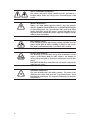
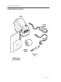
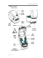
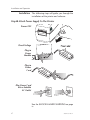
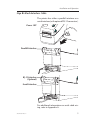
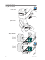
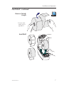
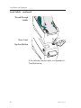
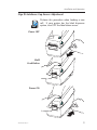
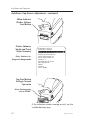
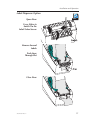
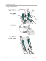
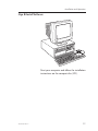
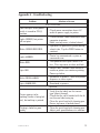
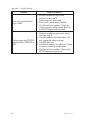
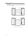
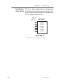
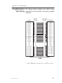
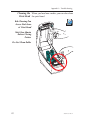
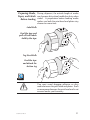
Thermal Printer User’s Manual 2824 User’s Manual No. 980346-001 Rev. A ©2001 Zebra Technologies Corporation ii 980346-001 Rev. A FOREWORD This manual provides installation and operation information for the LP 2824 series printers, manufactured by Zebra Technologies Corporation, Camarillo, California. COPYRIGHT NOTICE This document contains information proprietary to Zebra Technologies Corporation. This document and the information contained within is copyrighted by Zebra Technologies Corporation and may not be duplicated in full or in part by any person without written approval from Zebra Technologies Corporation. While every effort has been made to keep the information contained within current and accurate as of the date of publication, no guarantee is given or implied that the document is error-free or that it is accurate with regard to any specification. Zebra Technologies Corporation reserves the right to make changes, for the purpose of product improvement, at any time. TRADEMARKS LP 2824 is a service mark of Zebra Technologies Corporation. Windows and MS-DOS are registered trademarks of Microsoft Corp. All other marks are trademarks or registered trademarks of their respective holders. LP 2824 Thermal Printers European Council Directive 89/336/EEC 92/31/EE EMC Directive CB Schema Compliance to Standards EN 55022-B 1995 RF Emissions control EN 50082-1 1997 Immunity to Electromagnetic Disturbances IEC 1000-3-2 Harmonic Emmissions IEC 1000-3-3 Voltage Variation EN 60950 Safety FCC - DECLARATION OF CONFORMITY: Model: LP 2824 conforms to the following specification: FCC Part 15, Subpart B, Section 15.107(a) and Section 15.109(a) Class B digital device Supplemental Information: This device complies with Part 15 of the FCC Rules. Operation is subject to the following Two Conditions: (1) This device may not cause harmful interference , and (2) this device must accept any interference received, including interference that may cause undesired operation. INDUSTRY CANADA NOTICE: This device complies with Industry Canada ICS-003 class B requirements. Cet equipement est conforme a l’ICS-003 classe B de la norm Industrielle Canadian 980346-001 Rev. A iii SHOCK HAZARD WARNING: The printer and power supply should never be operated in a location where either one can get wet. Personal injury could result. MEDIA WARNING: Always use high quality approved labels, tags and transfer ribbons. If adhesive backed labels are used that DO NOT lay flat on the backing liner, the exposed edges may stick to the label guides and rollers inside the printer, causing the label to peel off from the liner and jam the printer. Approved supplies can be ordered from your dealer. RELOADING HINT: If you should run out of labels while printing, DO NOT turn the power switch OFF (0) while reloading or data loss may result. The printer will automatically a new label roll is loaded. STATIC DISCHARGE: The discharge of electrostatic energy that accumulates on the surface of the human body or other surfaces can damage or destroy the print head or electronic components used in this device. DO NOT TOUCH the print head or the electronic components under the top cover. THERMAL PRINTING: The print head becomes hot while printing. To protect from damaging the print head and risk of personal injury, avoid touching the print head. Use only the cleaning pen to perform maintenance. iv 980346-001 Rev. A TABLE OF CONTENTS Installation and Operation . . . . . Unpacking Your Printer . . . . . . Getting To Know Your Printer . . . Installation . . . . . . . . . . . . . AutoSense Gap Sensor Adjustment Label Dispenser Option . . . . . . Using Fan-Fold Media . . . . . . . . . . . . . . . . . . . . . . . . . . . . . . . . . . . . . . . . . . . . . . . . 1 2 3 4 8 10 11 Appendix A - Troubleshooting . . . . . . . . . . . . . . Serial Interface Cable Wiring. . . . . . . . . . . . . . . . Cash Drawer Cable Wiring . . . . . . . . . . . . . . . . Parallel Interface Cable Wiring . . . . . . . . . . . . . . . Cleaning the Print Head . . . . . . . . . . . . . . . . . . Preparing Media, Paper, and Labels Before Loading . . . . . . . . . . . . . . . 13 17 18 19 20 21 980346-001 Rev. A . . . . . . . . . . . . . . . . . . . . . . . . . . . . . . . . . . . . . . . . . . . . . . . . . . . . . . . v vi 980346-001 Rev. A 1 Installation and Operation This section provides information on the installation and operation of the printer. The printer is a low cost, desktop direct thermal printer. The printer is specifically designed for printing labels, tags or continuous receipts (with or without bar codes) from any DOS™, Windows™or ASCII-based compatible host. 980346-001 Rev. A 1 Installation and Operation Unpacking Your Printer 2 980346-001 Rev. A Installation and Operation Getting To Know Your Printer 980346-001 Rev. A 3 Installation and Operation Installation The following steps will guide you through the installation of the printer and software. Step ➊ Attach Power Supply To The Printer Power OFF Check Voltage Plug in Power Module Plug in Power Cord Plug Power Cord into a Suitable AC Outlet See the SHOCK HAZARD WARNING on page iv. 4 980346-001 Rev. A Installation and Operation Step ➋ Attach Interface Cable The printer has either a parallel interface or a serial interface (with optional RJ-11 connector). Power OFF Parallel Interface RJ-11 Interface (Optional) Serial Interface For additional information on serial cable wiring, refer to Appendix A. 980346-001 Rev. A 5 Installation and Operation Step ➌ Load Labels Power ON MOVIE Open Cover Adjust Holders 1.0 inch 2.5 cm MOVIE 1.5 inch 3.8 cm 6 980346-001 Rev. A Installation and Operation Load Labels - continued Remove Outside Length MOVIE For more information refer to appendix A Install Roll 980346-001 Rev. A 7 Installation and Operation Load Labels - continued Thread Through Guides Close Cover Tap Feed Button If the indicator remains dark, see Appendix A Troubleshooting. 8 980346-001 Rev. A Installation and Operation Step AutoSense Gap Sensor Adjustment MOVIE Perform this procedure when loading a new roll. If your printer has the label dispenser option, turn OFF the label taken sensor. Power OFF Hold Feed Button Power ON 980346-001 Rev. A 9 Installation and Operation AutoSense Gap Sensor Adjustment - continued When Indicator Flashes, Release Feed Button Printer Advances Media and Prints Status Summary Note: Printer is in diagnostic dump mode 4 MO3351F 16 V3.21 Serial port : 96,N,8,1 Image buffer size:245K Fmem:000,0K,019.9K avl Gmem:000K,0241K avl Emem:000K,0241K avl I8,0,001 rY S2 D8 R016,000 ZT UN q800 Q1029,025 Option: 04 08 13 now in DUMP Tap Feed Button To Begin Normal Operation Note: Printer prints “out of DUMP” If the indicator remains orange or red, see the troubleshooting steps. 10 980346-001 Rev. A Installation and Operation Label Dispenser Option Open Door MOVIE Use a Stylus to Switch On the Label Taken Sensor Remove Several Labels Push Liner Through Slot Close Door 980346-001 Rev. A 11 Installation and Operation Using Fan-Fold Media Open Guides to Width of Media Lock Guides in Place Insert Media Thread Media Through Guides 12 980346-001 Rev. A Installation and Operation Step ➎ Install Software Start your computer and follow the installation instructions on the compact disc (CD). 980346-001 Rev. A 13 Installation and Operation 14 980346-001 Rev. A Appendix A - Troubleshooting Problem Solution or Reason STATUS Indicator Does not light when power switch is turned to ON (I) position. 1. Check power connections from A.C. outlet to power supply to printer. Lights GREEN, but printer will not print. 1. Check interface cable connections from computer to printer. 2. Make sure top cover is locked closed. Blinks GREEN-RED-RED. 1. Operator has paused the printer during a batch job. Tap the FEED button to continue. Lights AMBER. 1. Printer has encountered a syntax or command error. Blinks RED. 1. The optional cover open sensor is active. Press top cover to close and lock. Lights RED. 1. Media is out. Reload a new source of media so printer can continue printing. 2. Power-up failure. Blinks GREEN-AMBER. 1. AutoSense in process. Wait until printer dispenses a status report. Lights AMBER-RED. 1. Download in process. Operation Printer appears to be working (media is being fed out), but nothing is printed. 1. Verify that the labels are the correct type (direct thermal). 2. Check that the roll is loaded with the direct thermal side facing up. 3. Clean the print head with cleaning pen. 4. Ensure top cover is locked closed. Printing is faded or poor quality. 1. Clean the print head with cleaning pen. 2. Adjust print speed/darkness in software. 980346-001 Rev. A 15 Appendix A - Troubleshooting Problem Solution or Reason Prints only partial label or skips a label. 1. Perform AutoSense gap sensor adjustment on page 8. 2. Label caught on print head. 3. Print head is not properly latched. 4. Possible software problem. Check the printer memory configuration. Refer to the EPL2 Programming manual. Printing stops and STATUS indicator lights ORANGE or RED. 1. Perform AutoSense gap sensor adjustment on page 8. 2. Possible problem with label stock. Use only approved labels and tags. 3. Possible label jam. 4. Insufficient memory for label size. Check the printer memory configuration. 5. Possible software problem. Refer to the EPL2 Programming manual. 16 980346-001 Rev. A Appendix A - Troubleshooting Serial Interface The figure below displays the cable wiring Cable Wiring required to use the printer's RS-232 serial interface. Host N/C RxD TxD DTR GND DSR RTS CTS RI DB-9 Pin # 1 2 3 4 5 6 7 8 9 DB-9 Pin # 1 2 3 4 5 6 7 8 9 Printer +5 Volts* TxD RxD N/C GND RDY N/C RDY N/C Female DB-9 to Male DB-9 Cable P/N 300017-006 (6') or 300017-010 (10') Host N/C RxD TxD DTR GND DSR RTS CTS RI DB-25 Pin # 8 3 2 20 7 6 4 5 22 DB-9 Pin # 1 2 3 4 5 6 7 8 9 Printer +5 Volts* TxD RxD N/C GND RDY N/C RDY N/C Female DB-25 to Male DB-9 Cable P/N 300018-006 (6') *+5 volts at 150 mA for external device (e.g. KDU or scanner) 980346-001 Rev. A 17 Appendix A - Troubleshooting Cash Drawer The figure below displays the pin assignments Cable Wiring for the printer's retail cash drawer interface. Refer to the cash draw manufacturer's documentation for proper drawer wiring. RJ-11 Pin No. PRINTER 1 2 3 4 5 6 SGND /SDRV1 /Sense +24V* /SDRV2 LGND Male RJ-11 *+24 volts D.C. at no greater than 1.5 amps. 18 980346-001 Rev. A Appendix A - Troubleshooting Parallel Interface The figure below displays the cable wiring Cable Wiring required to use the printer's Centronics parallel interface. HOST DB-25 Pin No. STROBE DATA 0 DATA 1 DATA 2 DATA 3 DATA 4 DATA 5 DATA 6 DATA 7 ACK/ BUSY PAPER ERR. READY INIT ERROR/ N/A N/A N/A SIG. GND SIG. GND SIG. GND SIG. GND SIG. GND SIG. GND SIG. GND 1 2 3 4 5 6 7 8 9 10 11 12 13 14 15 16 17 18 19 20 21 22 23 24 25 Centronics Pin No. PRINTER 1 2 3 4 5 6 7 8 9 10 11 12 13 14 15 16 17 18 19 20 21 22 23 24 25 STROBE DATA 0 DATA 1 DATA 2 DATA 3 DATA 4 DATA 5 DATA 6 DATA 7 ACK/ BUSY PAPER ERR. READY INIT ERROR/ N/A N/A +5V SIG. GND SIG. GND SIG. GND SIG. GND SIG. GND SIG. GND Female DB-25 to Male Centronics (Cable) +5 volts at 300 mA for external device (e.g. KDU or scanner) 980346-001 Rev. A 19 Appendix A - Troubleshooting Cleaning the When you load new media, you can also clean Print Head the print head. Rub Cleaning Pen Across Dark Area of Print Head MOVIE Wait One Minute Before Closing Printer Do Not Clean Roller 20 980346-001 Rev. A Preparing Media, During shipment, the outside length of media Paper, and Labels may become dirty when handled or dusty when Before Loading stored. A preparation before loading media makes sure both the print head and platen stay cleaner for more time. Label Rolls Find the tape and pull off both labels held by the tape Tag Stock Rolls Find the tape and detach the bottom tag MOVIE You must avoid dragging adhesive or dirty media between the print head and platen. Such an occurance damages the print head and is not covered under your warranty. 980346-001 Rev. A 21 980346- 001A