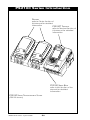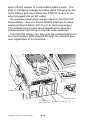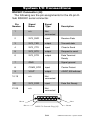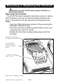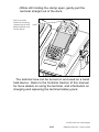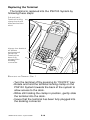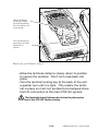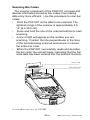
1
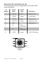
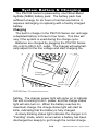
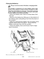
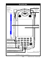
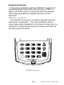
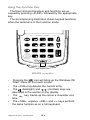
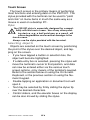
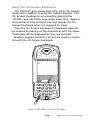
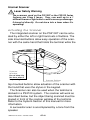
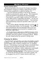
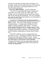
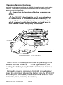
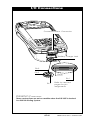
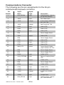
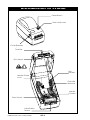
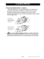
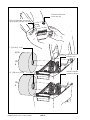
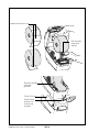
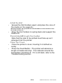
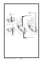
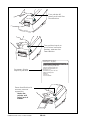
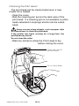
User's Manual
Part No. UMAN-PS21xx
Rev. 1.4 August, 2002
User's Manual
Proprietary Statement
This manual contains proprietary information of Zebra Technologies Corporation. It
is intended solely for the information and use of parties operating and maintaining
the equipment described herein. Such proprietary information may not be used,
reproduced, or disclosed to any other parties for any other purpose without the
expressed written permission of Zebra Technologies Corporation.
Product Improvements
Since continuous product improvement is a policy of Zebra Technologies
Corporation, all specifications and signs are subject to change without notice.
FCC Compliance Statement
NOTE: This equipment has been tested and found to comply with the limits for a
Class A digital device, pursuant to Part 15 of FCC Rules. These limits are designed
to provided reasonable protection against harmful interference when the equipment
is operated in a commercial environment. This equipment generates, uses, and can
radiate radio frequency energy and, if not installed and used in accordance with the
user’s manual, may cause harmful interference to radio communications. Operation
of this equipment in a residential area is likely to cause harmful interference in which
case the user will be required to correct the interference at his own expense.
Addtional RF safety information is contained in later sections of the manual devoted
to specific radio options.
NOTE: This unit was tested with shielded cables on the peripheral devices.
Shielded cables must be used with the unit to insure compliance with the rules.
Changes or modifications to this unit not expressly approved by Zebra Technologies
Corporation could void the user’s authority to operate this equipment.
Canadian Compliance Statement
“IC:” before the equipment certification number signifies that the INDUSTRY
CANADA technical specifications were met. IT DOES NOT GUARANTEE that the
certified product will operate to the user’s satisfaction.
Liability Disclaimer
Inasmuch as every effort has been made to supply accurate information in this
manual, Zebra Technologies Corporation is not liable for any erroneous information
or omissions. Zebra Technologies Corporation reserves the right to correct any such
errors and disclaims liability resulting therefrom.
No Liability for Consequential Damage
In no event shall Zebra Technologies Corporation or anyone else involved in the
creation, production, or delivery of the accompanying product (including hardware
and software) be liable for any damages whatsoever (including, without limitation,
damages for loss of business profits, business interruption, loss of business
information, or other pecuniary loss) arising out of the use of or the results of use of
or inability to use such product, even if Zebra Technologies Corporation has been
advised of the possibility of such damages. Because some states do not allow the
exclusion of liability for consequential or incidental damages, the above limitation
may not apply to you.
Copyrights
The copyrights in this manual and the system described therein are owned by Zebra
Technologies Corporation. All rights are reserved. Unauthorized reproduction of
this manual or the software in any of the system modules may result in
imprisonment of up to one year and fines of up to $10,000 (17 U.S.C.506).
Copyright violators may be subject to civil liability.
All products and brand names are trademarks of their respective companies. All
rights reserved.
©
2002 Zebra Technologies Corporation
Contents
PS2100 Series Introduction .......................OS-8
Terminal ...............................................................OS-9
Printer ..................................................................OS-9
Base .....................................................................OS-9
PS2100 Series Rear View .........................OS-10
System I/O Connections .......................... OS-11
RS232C Connector (J9) .................................... OS-11
Serial 8 Pin Din Connectors (J1-J5) .................. OS-12
System Battery & Charging .....................OS-13
Charging ............................................................OS-13
Run and Charge Mode ...................................... OS-14
Changing Batteries ............................................OS-15
Removing or Replacing the Terminal .....OS-16
Removing the Terminal ...................................... OS-16
Replacing the Terminal ...................................... OS-18
System Specifications .............................OS-20
Size/Weight ........................................................OS-20
Power .................................................................OS-20
Interfaces ...........................................................OS-20
Communications Protocol ..................................OS-20
Terminal Section: ...............................................OS-20
Printer Section ...................................................OS-21
System Environmental Characteristics .............. OS-21
PS2100T Introduction ................................ OT-1
Warning For Units Equipped With The WLAN Radio
Option .................................................................. OT-2
Controls....................................................... OT-3
Display ................................................................. OT-4
Keyboard Interface .............................................. OT-5
Touch Screen ....................................................... OT-8
Internal Scanner ................................................ OT-10
Scanning Bar Codes .......................................... OT-11
continued on next page
Battery Power ........................................... OT-12
Power Conservation .......................................... OT-12
Charging the Battery .......................................... OT-12
Changing Terminal Batteries .............................. OT-14
I/O Connections ........................................ OT-15
Communications Connector .............................. OT-16
Battery ............................................................... OT-17
Charger Jack ..................................................... OT-17
Terminal Specifications ........................... OT-18
Size/Weight ........................................................ OT-18
Display/ Touch Screen ....................................... OT-18
Keypad ............................................................... OT-18
Interfaces ........................................................... OT-18
Optional Radio Systems .................................... OT-19
Optional Built-in Scanner ................................... OT-19
Memory .............................................................. OT-19
Operating System .............................................. OT-19
Environmental Characteristics ........................... OT-19
Additional Features ............................................ OT-19
Printer Installation and Operation.............OP-1
Introduction to Printer ...............................OP-4
Loading Media ............................................OP-5
Preparing Media Before Loading ......................... OP-5
Loading Media .....................................................OP-7
Label Dispenser Option ........................... OP-11
Maintenance..............................................OP-13
Printer Troubleshooting ...........................OP-15
Status Indicator ..................................................OP-15
Operation ...........................................................OP-15
Patent Information ............... Inside Back Cover
PS2100 Series Introduction
PRINTERS
refer to Printer Section of
this Manual for detailed
information
PS2100T TERMINAL
refer to Terminal Section of
this Manual for detailed
information
PS2100 SERIES BASE
refer to this Section of the
Manual for detailed
information
PS2100 SERIES TRANSPORTABLE SYSTEM
(PS2122 shown)
UMAN-PS2100 Series • System Section
S-8
The PS2100 Series of transportable printing systems,
consist of a terminal and configurable combinations of
printer modules integrated into a base which provides
power, charging and interface capabilities.
Terminal
The terminal section of the PS2100 Series is a
PS2100T terminal/scanner with a touch-screen display
and a alpha numeric keypad for data entry. It utilizes the
Microsoft Windows® CE operating system.
The terminal of the PS2100 Series is a docking terminal, which can be removed from the PS2100 Series
Transportable System and used independently as a
hand-held terminal/scanner.
Complete information regarding the features and use of
the terminal can be found in the Terminal Section of this
manual.
Printer
There are two printers which can be specified in a
PS2100 Series system: a unit which prints on 2” wide
media, and a larger one using 4” media. Both printers
use direct thermal media and are specifically designed for
printing labels, tags or continuous receipts (with or without bar codes) from the PS2100T terminal.
Following is a table describing the printer configurations
available on PS2100 series printing systems.
Model
PS2102
Printers
1
PS2122
2
Complete information regarding the features and use of
the printer module can be found in the Printer section of
this manual.
Base
The Base of the PS2100 Series Transportable System
acts as the infrastructure linking the terminal and the
printer(s). It provides power to run all modules for a full
S-9
UMAN-PS2100 Series • System Section
work shift by means of a removable battery pack. The
built in intelligent charger provides rapid charging for the
main battery and also allows the PS2100 Series to run
when plugged into an AC outlet.
Six external serial ports are provided on the PS2100
Series Base. One is a 25 pin RS232 interface to allow
serial communications to P.C.s or in-store processors.
The remaining five ports are multiplexed to allow the
simultaneous input of up to five bar code scanners.
The PS2100 Series can also provide communication to
the host facility’s data network through the optional wireless capabilities of the terminal.
Scanner Window
J1 J2
J3
J4
J5
RS232 I/O Port (J9)
Battery Door
Charger A.C.
Receptacle Serial I/O Ports (J1-J5)
PS2100 Series Rear View
UMAN-PS2100 Series • System Section
S-10
System I/O Connections
RS232C Connector (J9)
The following are the pin assignments for the 25-pin DSub RS232C serial connector.
Pin
Number
Signal
Name
Signal
Type
1
n/c
Not
connected
2
SYS_RXD
input
Receive Data
3
SYS_TXD
output
Transmit data
4
SYS_CTS
input
Clear to Send
5
SYS_RTS
output
Request to send
6
SYS_DTR
output
Data Terminal
Ready
7
GND
8
COM2_DCD
input
Carrier Detect
9
VOUT
output
+5VDC, 500 mA max.
n/c
Not
connected
SYS_DSR
input
n/c
Not
connected
10-19
20
21-25
Description
Signal ground
Data Set Ready
Pin 13
Pin 1
Pin 25
Pin 14
DB-25 Pin Female Plug (J9)
S-11
UMAN-PS2100 Series • System Section
Serial 8 Pin Din Connectors (J1-J5)
The following are the pin assignments for the 8-pin DIN
serial connectors
Pin
Number
Signal
Name
Signal
Type
Description
1
RXD IN
input
Receive Data
2
TXD IN
output
Transmit data
3
CTS IN
input
Clear to Send
4
RTS OUT
output
Request to send
5
GND
6
n/c
Not
connected
7
n/c
Not
connected
8
+5VDC
output
Signal ground
+5VDC, 250 mA max.
8
7
6
3
1
5
4
8 Pin
Serial Port
J1-J5
UMAN-PS2100 Series • System Section
S-12
2
System Battery & Charging
The PS2100 Series is powered by one Nickel-Metal
Hydride (NiMH) battery pack. The battery pack has
sufficient energy for six hours of normal use before it
requires recharging or replacing with a freshly charged
battery.
Charging
The built in charger in the PS2100 Series can recharge
a depleted battery in three to four hours. This time will
vary if the system is used during the charge cycle.
Batteries are charged by plugging the PS2100 Series
into a 90 to 230 V.A.C. outlet. The charger will automatically adjust for the line voltage and start charging the
Charger
Status Light
System
Power Light
PS2100 SERIES CHARGER INDICATORS
battery. The charger power light will come on to indicate
the unit is running on A.C. power, and the charge status
light will also turn on. When the battery reaches its
maximum charge, the charge status light will start to
blink, indicating that the battery is fully charged.
A slowly blinking status light indicates the charger is in
“Pending” mode, which occurs when a battery has been
discharged too deeply to go through the normal charge
S-13
UMAN-PS2100 Series • System Section
cycle (e.g. a battery that has been stored too long and
allowed to discharge). When in the “Pending” mode the
PS2100 Series charger will slowly bring this battery’s
charge state up to a level where it can safely withstand a
fast charge, and then charge it normally. When the
charger is in the “Pending” mode, run and charge operations are not available.
Run and Charge Mode
The PS2100 Series system can be used normally while
its battery is being charged. The charger indicator lights
will operate as usual, however, charge time will be longer.
Under severe system usage, the charge status indicator
may turn on steadily, as the charger switches to its “Fast
Charge” mode. This is a normal occurrence, and once
the battery’s charge level has been restored, the charge
status indicator will return to its blinking state.
If the charger is in the “Pending” mode, the Run and
Charge mode is disabled.
UMAN-PS2100 Series • System Section
S-14
Changing Batteries
Always turn the terminal off before changing batteries!
The terminal is powered by its own battery when main
power to the system is turned off and will retain its data
when the main battery is removed. Insure that you have
a fully charged replacement battery on hand, and install
the new battery as quickly as possible.
• Open the battery door and let it drop away from
the unit.
• Remove the battery by lifting up on the bottom of
the battery pack and pulling it out from the back of
the system.
• Slide the replacement battery into the back of the
system until it clicks into place. Insure that the
battery terminals face into the system.
• Close the battery door and insure that it snaps
back into place.
Battery Pack
A.C. Outlet
Battery Pack Door
REPLACING BATTERIES IN THE PS2100 SERIES
S-15
UMAN-PS2100 Series • System Section
Removing or Replacing the Terminal
Always turn the PS2100 Series system off before removing the terminal.
Removing the Terminal
The PS2100 Series System’s terminal section is removable to allow its use as a hand held data collection device. The terminal can be removed by following these
steps:
• Turn the PS2100 Series system off by pressing the
terminal’s “ON/OFF” key.
• Turn the terminal locking key at the back of the unit
a quarter turn until it is loose.
• Rotate the Terminal locking clamp away from the
terminal.
Always turn terminal
off before removal!
2. Pull Terminal
Locking Clamp
open and hold in
place
1. Rotate Terminal
Lock 1/4 turn
REMOVING THE TERMINAL: STEP 1
UMAN-PS2100 Series • System Section
S-16
• While still holding the clamp open, gently pull the
terminal straight out of the dock.
Pull and hold
Terminal Locking
clamp back and
slide terminal out
of the dock.
The terminal now can be turned on and used as a hand
held device. Refer to the Terminal Section of this manual
for more details on using the terminal, and information on
charging and replacing the terminal battery pack.
continued on next page
S-17
UMAN-PS2100 Series • System Section
Replacing the Terminal
The terminal is replaced into the PS2100 System by
following these steps:
Pull and hold
Terminal Locking
clamp back and
slide terminal into
dock.
Always turn terminal
off before
replacement!
Insure that
Terminal has
been fully
plugged into
docking
connector
REPLACING THE TERMINAL: STEP 1
• Turn the terminal off by pressing its “ON/OFF” key.
• Rotate and hold the terminal locking clamp on the
PS2100 System towards the back of the system to
allow access to the dock.
• While still holding the clamp in position, gently slide
the terminal into the dock.
• Insure that the terminal has been fully plugged into
the docking connector
UMAN-PS2100 Series • System Section
S-18
Allow Terminal
Locking Clamp
to set into place.
Do not allow it to
snap back.
Turn Locking Key
as shown to lock
Terminal in
place.
REPLACING THE TERMINAL: STEP 2
• Allow the terminal clamp to slowly return to position
to secure the terminal. Don’t let it snap back into
place.
• Turn the terminal locking key at the back of the unit
a quarter turn until it is tight. This retains the terminal in place so it will not accidently be bumped loose
from its connection to the main PS2100 system.
The terminal should always be locked in place prior
to its use in the PS2100 Series system.
S-19
UMAN-PS2100 Series • System Section
System Specifications
Size/Weight
Model
PS2102
PS2122
width
depth
height
13.5”
343 mm
19.5”
494 mm
11”
279mm
11”
279mm
8.5”
216 mm
8.5”
216 mm
weight
12 lb.
5.44 Kg
16#
7.26 Kg
Weights are with battery, less printing media)
Power
• 7.2VDC, 7000 mAHr Nickel Metal Hydride (NiMH)
Battery Pack
• Built in intelligent battery charger, 110-230 V.A.C.
input.
Interfaces
• One (1) DB25F Connector RS-232 port for one-way or
two-way communications up to 38.4K BPS. (J9)
• Five (5) multiplexed 8 pin circular DIN Connectors, for
one-way or two-way communications. (J1-5)
Communications Protocol
Supports RTS/CTS (hardware) and XON/XOFF handshaking protocols to synchronize with the host terminal.
The handshaking protocol and the baud rate is programmable. The default communications parameters are:
Handshaking = RTS/CTS
Parity = None
Baud Rate = 19,200
Data Bits = 8
Terminal Section:
Windows CE based docking (removable) terminal.
• LCD Display/ Touch Screen
• 19 Key Keypad
• Optional built-in Laser Scanner
• Optional RF LAN module
See the Terminal Section of this manual for complete
terminal specifications
UMAN-PS2100 Series • System Section
S-20
Printer Section
Configurable with one or two printers, depending on
model:
• 2” wide media, 200 d.p.i
• 5” diameter media roll capacity (approx. 450’ [137 m]
@.0035” thick stock)
• Self-centering stock adjustment with position locking
capability.
• Optional label dispenser with label taken detection
circuitry
System Environmental Characteristics
• Operating temperature: 4˚ to 110˚F (-16˚ to 43˚C)
• Storage temperature: -4˚ to 122˚F (-20˚ to 50˚C)
• Relative humidity:
45%-95% non-condensing @
77°F (25°C)
• Water Resistance: NEMA2
• Drop Test: One (1) 3’ (.9 m) drop to concrete on each
side, per UL 1950 sec. 4.2.5.
S-21
UMAN-PS2100 Series • System Section
Terminal Section
PS2100T Introduction
The PS2100T is a highly integrated, light weight scanner/terminal. Its compact one-piece design minimizes
operator fatigue and promotes more efficient and accurate operation. The PS2100T’s innovative design also
provides for “either hand” scanning to promote operator
comfort.
The PS2100T utilizes the Microsoft Windows® CE
operating system and a touch-screen display. Operators
already familiar with Windows will quickly become productive with the PS2100T due to its familiar user interface.
The PS2100T's powerful CPU, combined with sophisticated RF communications, an IR communications port
and an accurate and reliable laser scanner combine to
make the PS2100T a highly versatile terminal that can be
easily integrated into virtually any data processing network.
The PS2100T serves as a fully integrated component of
the PS2100 Series printing systems. The various models
of the PS2100 Series are complete mobile printing package consisting of the PS2100T terminal, a configurable
combination of 2” and 4” thermal printers, inputs for
multiple scanners, connections to facility-wide data networks, and a high capacity battery and charger.
The PS2100T as used in a PS2100 Series Printing
System is a docking terminal. It can be removed from a
PS2100 Series System and used as an independent
hand held terminal.
Some PS2100T features described in this manual may
work differently when the unit is docked in a PS2100
Printing System. This section will cover these exceptions
when they arise.
continued
OT-1
UMAN-PS2100 Series • Terminal Section
Warning for units equipped with the WLAN radio
option:
The following section only applies when the PS2100T terminal has FCC ID:
I28PS21224121 on the the serial number label. (This label is on the underside of
the terminal.)
Warning: Use of the PS2100T as a handheld ter minal with FCC ID: I28PS21224121 meets the FCC requirements for radio frequency (RF) radiation exposure. To
minimize exposure the user should avoid holding the
terminal, especially the scanner end, up to his/her head
or torso. The terminal with this radio option has been
SAR tested. The maximum SAR value measured was 0.18
W/kg averaged over 1 gram.
Warning: Use of the PS2122 printer with the above
PS2100T terminal docked in the cradle meets the FCC
requirements for radio frequency (RF) radiation exposure. To minimize exposure the user should avoid leaning over the docked terminal, especially the scanner
end. The PS2122 with this terminal/radio option has been
SAR tested. The maximum SAR value was 0.17 W/kg averaged over 1 gram.
UMAN-PS2100 Series • Terminal Section
OT-2
Controls
Speaker
Reset Button
Scanner
Buttons
refer to pg.
OT-10
Scanner
Buttons
refer to pg.
OT-10
Stylus
Touch Screen
refer to pg.0T-7
Alpha Key
refer to pg. O-6
Function Key
refer to pg.O-5
On/Off Switch
Alternate action
Power switch
Charging Indicator
Alpha Indicator
Microphone (optional)
PS2100T CONTROLS
OT-3
AND DISPLA Y
UMAN-PS2100 Series • Terminal Section
Display
The display for the PS2100T is an 240 by 320 pixel
liquid crystal graphics display with backlighting and four
shades of gray. It is equivalent to 1/4 of a standard VGA
display. The display is integrated with a touch screen
which enables the user to enter data by means of a
stylus. Use of the touch screen is detailed later in the
Controls Section.
Backlight:
The PS2100T allows the user to enable and disable the
LCD backlight by pressing <FTN>
(4). The backlight
remains on until the <FTN>
(4) sequence is pressed
again. For example, with the backlight off, pressing
<FTN>
(4) will turn the backlight on.
There is an additional power drain on the battery with
the display backlight enabled. The application in the unit
may turn the backlight on or off with no input from the
user to extend battery life.
Contrast:
Pressing <FTN>
(<) will cause the contrast to become lighter with each successive keystroke.
Pressing <FTN> (>) will cause the contrast to become darker with each successive keystroke.
UMAN-PS2100 Series • Terminal Section
OT-4
Keyboard Interface
Data entry capabilities with the PS2100T keypad can
be expanded by using either the Function <FTN> or
Alpha <ALPHA> keys in conjunction with the keypad.
The following details the keypad functions of the
PS2100T.
Default functions
The terminal is set up as a numeric keypad as its default mode of operation. The horizontal and vertical
cursor keys allow navigation on the touch screen as on a
normal P.C. keyboard and only the numeric functions of
the main keys are active.
PS2100T DEF AULT KEYS
OT-5
UMAN-PS2100 Series • Terminal Section
Using the Function Key
The blue colored characters and functions are accessed by pressing <FUNC> followed by the appropriate
key.
The accompanying illustration shows keypad functions
when the terminal is in the Function mode.
PS2100T F
•
•
•
•
•
UNCTION K EYS
icon will bring up the Windows CE
Pressing the
“Start” menu on the touch screen.
The <CLR> key deletes the current entry.
The
(backlight) and
(contrast) keys are
described in the section on the display.
The
key backs up the cursor a character at a
time.
The <TAB>, <space> <DEL> and <.> keys perform
the same function as on a full keyboard.
UMAN-PS2100 Series • Terminal Section
OT-6
Using the Alpha Keys
Alpha characters on the keypad are accessed by
pressing the <ALPHA> key followed by pressing the key
with the desired character the appropriate number of
times. For example, the letter “C” is accessed by
pressing the <ALPHA> key followed by pressing the
key three times. If the next character that is needed is on
a different key then pressing that key will advance the
cursor ton the next character. If, however, as in the
example above we wanted “C” to be followed by “A” we
would need to advance the cursor to the next character
by using the right cursor key (>) and then press
once to enter “A”.
Alpha Indicator
PS2100T A
LPHA
K EYS
Notes:
• The “S” and the “Z” characters are produced by
pressing the appropriate character key four times.
• Alpha keys produce only upper case alpha characters.
• The cursor keys stay active in the Alpha mode.
• The Alpha function stays active until the <ALPHA>
key is pressed again. An indicator at the bottom of
the keypad indicates the terminal is in Alpha mode.
OT-7
UMAN-PS2100 Series • Terminal Section
Touch Screen
The touch screen is the primary means of performing
most functions and entering data on the PS2100T. The
stylus provided with the terminal can be used to “point
and click” on menu items in much the same way as a
mouse is used on a desktop PC .
Stylus
The PS2100T stylus is especially designed for compatibility with the touch screen. Use of any other pointing device, e.g. a ball point pen or a pencil, will
cause degradation and eventual damage to the
touch screen.
Always use the stylus provided with the ter minal.
Selecting objects
Objects are selected on the touch screen by positioning
the point of the stylus over the desired object, and tapping on the screen.
• If you have tapped a button or selection box, the
object will become highlighted.
• If a data entry box is selected, pressing the stylus will
move the terminal’s cursor to that position, and data
can now be entered either via the various touch
screen options, or by means of the terminal’s keypad.
Refer to the section below on using the On-Screen
Keyboard, or the previous section on using the Numeric Keypad.
• Double-tapping an application or document icon will
open it.
• Text may be selected by firmly sliding the stylus tip
over the desired characters.
• Control sliders, and the elevator boxes on the display
can be also moved by sliding the stylus.
UMAN-PS2100 Series • Terminal Section
OT-8
Using the On-Screen Keyboard
The PS2100T also allows data entry via its On-Screen
Keyboard in addition to using the numeric keypad. The
On-Screen Keyboard is accessed by pressing the
<FUNC> and <ALPHA> keys at the same time. Applications written for the terminal may also display the OnScreen Keyboard when it is required for input.
Once the On-Screen Keyboard is displayed, data can
be entered by tapping on the desired key with the stylus.
Characters will be displayed as they are touched.
Numeric keypad functions can also be used in conjunction with the On-Screen keyboard.
U SING THE PS2100T O N-S CREEN K EYBOARD
OT-9
UMAN-PS2100 Series • Terminal Section
Internal Scanner
Laser Safety Warning
The scanners used on the PS2100T or the PS2100 Series
Systems are Class II lasers. They can emit up to a 1
milliwatt beam of light which could cause eye damage
if stared at directly. Do not stare into a laser when it is
operating!
Actuating the Scanner
The integrated scanner on the PS2100T can be actuated by either the left or right hand sets of buttons. The
side mounted buttons allow easy operation of the scanner with the same hand that holds the terminal while the
Scanner
Window
Do not stare into
the laser when it
is operating!
Scanner Buttons
top mounted buttons allow actuation of the scanner with
the hand that uses the stylus or the keypad.
The Scanner can also be used when the terminal is
docked in a PS2100 system. The scanner will work as
described below, but the object being scanned must be
placed in front of the scanner window of the terminal.
Refer to the System Section of this manual for more
information.
A successful scan is accompanied by a tone from the
speaker.
UMAN-PS2100 Series • Terminal Section
OT-10
Scanning Bar Codes
The scanner component of the PS2100T can read and
decode information stored as bar codes, thus making
data entry more efficient. Use this procedure to scan bar
codes:
• Point the PS2100T at the label to be scanned. The
optimum range of the scanner is approximately 2.514” [6.4-35.5 cm]
• Press and hold the one of the scanner buttons to start
scanning.
• A line of light will appear on the surface you are
scanning. Position the line perpendicular to the lines
of the barcode being scanned and ensure it crosses
the entire bar code.
• When the PS2100T successfully reads and decodes
the bar code, the unit will beep, indicating that the bar
code data has been entered into the terminal memory.
Scan Line
Scan Buttons
S CANNINGB ARCODES WITH
THE
PS2100T
OT-11
UMAN-PS2100 Series • Terminal Section
Battery Power
Power Conservation
Maximizing battery life insures the longest operating
time between charging or battery replacement cycles.
Follow these guidelines to optimize battery life:
• Turn the terminal off when it will not be used for
key. This suspends
awhile by pressing the green
terminal operation and allows it conserve power.
Pressing the
switch again restores the PS2100T
to its state prior to suspending operation. You do not
have to wait for the terminal to restart. The terminal
will automatically suspend operation after a pre-set
interval.
(4)
• Turn off the display backlight with the <FTN>
key combination when it is not needed. The terminal
will automatically dim the backlight after a pre-set
period of inactivity if that function is enabled in the
terminal’s application.
• If the terminal is docked in a PS2100 Series Printing System connect the unit to A.C. power whenever
possible using the system’s charging system. Batteries will charge while the system is being used.
Charging the Battery
The PS2100T will alert the user when the battery needs
charging. The user then has the option of either replacing the battery with a freshly charged one, or charging
the unit. If the battery is run down below a minimum limit,
the terminal will suspend operations and cannot be
restarted until the battery is either replaced or recharged.
There are two options for charging the PS2100T:
• PS2100 Printing System. If the terminal is docked
in a PS2100 Printing System, the entire system can
be plugged into an A.C. power source and it will
UMAN-PS2100 Series • Terminal Section
OT-12
continue to operate normally while its battery is recharged. Refer to the System Section of this manual
for more information on charging batteries in the
PS2100 Printing System.
• The LI72 Wall Charger (p/n AT15759-tab)
The LI72 is a wall mounted single charger with
universal 110 to 230, 50-60 Hz. VAC input. The
charger can be configured with plugs which comply
with most international standards. The LI72 Charger
can only be used when the terminal is not docked in a
PS2100 Series system.
Plug the LI72 Charger into the appropriate A.C.
power source, and the charger plug into the PS2100T
Battery Pack. The LED on the charger will report
charging status. A steady light indicates that the
battery is being charged (“fast mode”). A slowly
blinking light indicates that the charge cycle is complete and the charger is now in “trickle charge” mode.
A rapidly blinking light indicates a charging problem
and the battery undergoing a charge may be defective.
PS2100T batteries can be charged while the
terminal is in use. Charging the battery with the Wall
Charger will take approximately 4 hours. Actual
charging time will depend on the battery pack’s condition and usage of the terminal while charging.
Charger part numbers will vary depending on specific
country of use. Consult Zebra for the corr ect part number for your application.
OT-13
UMAN-PS2100 Series • Terminal Section
Changing Terminal Batteries
Terminals must be removed from the PS2100 Printing System to replace their
batteries. Refer to the System section for instructions on removing and
replacing docking terminals.
Always turn the ter minal off before changing batter ies!
The PS2100T will retain data and its curr ent settings
for a maximum of five minutes when its battery is removed. Before changing batteries, insure that you have
a fully charged replacement battery on hand, and install the new battery as quickly as possible.
Release Latch
Charger Jack
CHANGINGBATTERIES
IN THE
PS2100T
The PS2100T’s battery is removed by pressing on the
release latch as shown at “1” in the figure below, and
pivoting the battery away from the terminal as shown at
“2”.
Follow the reverse procedure to install a new battery:
Insert the alignment tabs on the battery into the PS2100T
and then pivot the battery into the terminal until the latch
clicks into place, retaining the battery.
UMAN-PS2100 Series • Terminal Section
OT-14
I/O Connections
Communications Connector
Battery Charge Jack
Pin 2
Pin 3
Pin 26
Pin 1
Pin 1
Refer to next two
pages for pin
assignments
PS2100T I/O C ONNECTIONS
These connections are not accessible when the PS2100T is docked
in a PS2100 Printing System.
OT-15
UMAN-PS2100 Series • Terminal Section
Communications Connector
The following are the pin assignments for the 26-pin
communications/power connector.
Pin
Number
Signal
Signal
Name
Type
Description
1
AUX_SELB#
input
Docking signal- short to
pin 26 when docked
2
+AUX
input
Aux Power input
3
+AUX
voltage
6.9-9.0 VDC/1.25AFused
3A./ 10V TVS
4
+AUX
voltage
Not Fused/10V TVS
5
DCD1
input
COM1 (DTE)
6
DSR1
input
COM1 (DTE)
7
RXD1
input
COM1 (DTE)
8
RTN
9
TXD1
10
RTN
11
RTS1
output
COM1 (DTE)
12
CTS1
input
COM1 (DTE)
13
DTR1
output
COM1 (DTE)
14
PWR_CTL
output
Printer Power Enable
(Open Collector 10V TVS)
15
RTN
Power Supply Return
16
RTN
Power Supply Return
17
RXD2
input
COM2 (DTE)
18
CHG_STATUS#
input
Battery Charging Status
LED
19
TXD2
output
COM2 (DTE)
20
RTN
21
RTS2
output
COM2 (DTE)
22
CTS2
input
COM2 (DTE)
23
+CHG
input
Charger input
24
+CHG
voltage
9.0VDC max/2.225A.
max.
25
+CHG
input
Charger input
26
AUX_SELA#
input
Docking signal- short to
pin 1 when docked
UMAN-PS2100 Series • Terminal Section
Power Supply Return
output
COM1 (DTE)
Power Supply Return
Power Supply Return
OT-16
Battery
The PS2100T utilizes a removable 7.2 VDC LiION
battery pack with an integral charger jack. If not in use,
the terminal will automatically power off to conserve
battery life. The inactivity time-out value can be programmed; the default time-out is one minute. Other
power features:
• Full charge lasts approximately_ when terminal is
not docked.
• Low battery indicated by audible beeps and low
battery message on display
• Battery includes overcharge protection circuitry.
Charger Jack
Pin
Number
Signal
Name
1
+V
2
PWR
3
-V
Description
Charge voltage
Provides power when docked in
a PS2100 Printing System
Ground
OT-17
UMAN-PS2100 Series • Terminal Section
Terminal Specifications
Size/Weight
7.53”1
[191.3 mm]
1.71”1
[43.4 mm]
3.27”1
[83.1mm]
Weight: 1 lb. (with Battery)1
Display/ Touch Screen
• 240 x 320 pixels (1/4 VGA), transflective backlit, FSTN
liquid crystal display (LCD)
• Three shades of gray plus white
• Integrated resistive non-glare touch screen
Keypad
• 19 Key alphanumeric elastomer
Interfaces
• Two RS-232 ports for one-way or two-way
communication to terminal or printer at up to 115K
BPS.
UMAN-PS2100 Series • Terminal Section
OT-18
Optional Radio Systems
• Short Range (SRRF) System: 916MHz or 2.4 GHz
Compatible with SRRF equipped Zebra printers.
• Long Range System: per 802.11b, supports qualified
radio cards via internal PCMCIA port. Allows
integration with facility-wide LANs.2
Optional Built-in Scanner
• Visible laser diode
• Scan rate = 36 +/- 3 scans per second
• CDRH Class II
• Range (10 mil) = 2.5-14 inches
Memory
• Flash Memory: 4MB std. 8MB optional
• DRAM Standard configuration: 16MB
Operating System
• Microsoft Windows CE® v3.00 or higher
Environmental Characteristics
• Operating temperature: 32˚ to 122˚F (0˚ to 50˚C)
• Storage temperature: 5˚ to 150˚F (-15˚ to 65˚C)
• Relative humidity:
45%-95% non-condensing
• Water Resistance: NEMA3R for water and dust
resistance1
• Drop Test: Three (3) consecutive 4’ (1.2 m) drops to
concrete.1
Additional Features
• 80 MHz processor speed
• Integrated real time clock and date
• Special touch screen stylus included
• Dockable with PS2100 Series Printing Systems
1. Specs do not apply to unit docked in a PS2100 series system.
2. Refer to warnings regarding RF frequency radiation in the Introduction of
this section.
OT-19
UMAN-PS2100 Series • Terminal Section
Printer Section
Printer Installation and Operation
This section provides information on the operation
and maintenance of the PS2100 series printers.
Printers used in PS2100 series system print on 2”
wide media, and use direct thermal media. They are
specifically designed for printing labels, tags or continuous receipts (with or without bar codes) with the
PS2100T terminal.
OP-1
UMAN-PS2100 Series • Printer Section
Warnings
SHOCK HAZARD WARNING:
The printer and power supply should never
be operated in a location where either one
can get wet. Personal injury could result.
MEDIA WARNING:
Always use high quality approved labels, tags
and transfer ribbons. If adhesive backed labels
are used that DO NOT lay flat on the backing
liner, the exposed edges may stick to the label
guides and rollers inside the printer, causing the
label to peel off from the liner and jam the printer. Approved supplies can be ordered from your
dealer.
RELOADING HINT:
If you should run out of labels while printing,
DO NOT turn the printer OFF while reloading or
data loss may result. The printer will automatically resume printning when a new label roll is
loaded.
STATIC DISCHARGE:
The discharge of electrostatic energy that accumulates on the surface of the human body or
other surfaces can damage or destroy the print
head or electronic components used in this
device. DO NOT TOUCH the print head or the
electronic components under the top cover.
THERMAL PRINTING:
The print head becomes hot while printing. To
protect from damaging the print head and risk of
personal injury, avoid touching the print head.
Use only the cleaning pen to perform maintenance.
UMAN-PS2100 Series • Printer Section
OP-2
Thermal Printers Compliance
EC Compliance
European
Council
Directive
89/336/EEC
Compliance to Standards
EN 55022-B 1995
92/31/EE
EN 50082-1 1997
EMC Directive
CB Schema
RF Emissions control
Immunity to Electromagnetic Disturbances
IEC 1000-3-2
Harmonic Emmissions
IEC 1000-3-3
Voltage Variation
EN 60950
Safety
FCC - Declaration of Conformity:
Model: LP _ conforms to the following specification:
FCC Part 15, SubpartB, Section15.107(a)
and Section15.109(a) Class B digital device
Supplemental Information:
This device complies with Part 15 of the FCC Rules. Operation is
subject to the following Two Conditions: (1) This device may not cause
harmful interference, and (2) this device must accept any interference
received, including interference that may cause undesired operation.
Industry Canada Notice:
This device complies with Industry Canada ICS-003 class B requirements.
Cet equipementestconforme a l’ICS-003 classe B de la norm
IndustrielleCanadian
OP-3
UMAN-PS2100 Series • Printer Section
Introduction to Printer
Feed Button
Status Indicator
Cover Release
Tear Bar
Print Head
Roll
Holders
Media Guide
Lock
Core size
Selectors
Media
Guides
Gap Sensor
LabelTaken
Sensor
UMAN-PS2100 Series • Printer Section
OP-4
Loading Media
Preparing Media Before Loading
During shipment, the outside length of media may
become dirty when handled or dusty when stored.
Preparing media before loading it into the printer
makes sure both the print head and platen stay cleaner
for a longer time.
Label Rolls
Find the tape
and pull off both
labels held by
the tape
Tag Stock Rolls
Find the tape
and detach the
bottom tag
You must avoid dragging adhesive or dirty media between the print head and platen. Such an occurrence damages the print head and is not covered under your warranty.
OP-5
UMAN-PS2100 Series • Printer Section
Power Indicator
must be on.
Pull on Release Levers,
and open printer cover
r
1” [25 mm] core
ers
Adjust media
holders up
ch
m
Adjust media
holders down
1.5” [38 mm] core
ch
m
UMAN-PS2100 Series • Printer Section
OP-6
Loading Media
T urn the power “On”
Press the “On/Off” button on the terminal. The indicator surrounding the printer’s feed button should light
up.
Open the Printer Cover
Pull on the Cover Release levers as shown, and
rotate the cover up.
Adjust the Core Size Selectors
• If the roll of media has a small (1” [25 mm]) core,
push the selectors up as shown.
• If the roll of media has a large (1.5” [38 mm]) core,
push the selectors down as shown.
continued on next page
OP-7
UMAN-PS2100 Series • Printer Section
Labels must face up
Pull media
supports
apart.
Thread media
through
guides
Close Cover
Press feed
button to
advance
media
UMAN-PS2100 Series • Printer Section
OP-8
Install the Roll
• Spread the Roll Holders apart, and place the core of
the media on the supports.
Note that media can spool off the roll with labels on the outside or from
the inside of the roll.
•
Allow the Roll holders to spring back and support the
media roll.
Thread MediaThrough the Guides
Note that the side to be printed must face up as it
emerges from the printer.
Close the Cover
• Close the printer’s cover, insuring it is latched securely.
• Press the Feed Button. The printer will advance a
length of media and stop. The indicator around the
feed button should be lit. If it is still dark, refer to the
Troubleshooting section.
OP-9
UMAN-PS2100 Series • Printer Section
Close
Dispenser
Door
Open
Dispenser
Door
Remove several
Labels
Switch
Push Liner Through
Slot
UMAN-PS2100 Series • Printer Section
OP-10
Label Dispenser Option
Printers can be equipped with a label dispenser
which when utilized will print a label and automatically
separate it from its backing and present ti for the user
to apply. A ‘label taken” sensor will prevent printing any
further labels until the one presented is removed.
The Dispenser works as detailed below:
Set the LabelTaken Sensor
• Pull open the label dispenser door.
• Use a stylus to set the Label Taken Sensor to the
“1” position.
Load Media
• Remove several labels from the roll of media.
• Slide the backing through the slot under the dispenser door as shown.
Close Door
Close the label dispenser door as shown. The printer
is new ready to print, separate and dispense labels.
OP-11
UMAN-PS2100 Series • Printer Section
T urn printer off,
press and hold the
Feed Button
T urn printer back on
and when indicator
flashes, release the
Feed Button
4 MO3351F 16 V3.21
Serial port : 96,N,8,1
Summary Status
report is printed
Image buffer size:245K
Fmem:000,0K,019.9K avl
Gmem:000K,0241K avl
Emem:000K,0241K avl
I8,0,001 rY
S2 D8 R016,000 ZT UN
q800 Q1029,025
Option:
04 08 13
now in DUMP
Press feed Button to
resume normal
operation.
Note: the
printer will
print “out of
DUMP”
UMAN-PS2100 Series • Printer Section
OP-12
Maintenance
AutoSense Gap SensorAdjustment
This procedure is also known as a “two-key reset”. It
forces the printer to print out a summary of its current
status and places the printer into a diagnostic mode. In
this mode it will only print the raw code sent to it by the
PS2100 terminal, and will not create any labels.
If you have turned on the Label Taken Sensor, you must turn it off prior
to performing this step.
• Turn the printer off by pressing the “ON/Off” key on
the PS2100 terminal.
• Press and hold down the Feed Button on the printer
under test.
• Turn the printer back on by pressing the “ON/Off”
key on the PS2100 terminal again.
• When the indicator around the Feed Button flashes,
release the Feed Button.
The printer will advance media and then print out a
status report as shown. It is now in its diagnostic
“DUMP” mode.
• Tap the feed button again. The printer will print “out
of DUMP” and can resume normal operation. Remember to turn the Label Take Sensor switch back
to “1” if you are using this feature.
OP-13
UMAN-PS2100 Series • Printer Section
Cleaning the Print Head
The print head can be cleaned whenever a new
media roll is loaded.
• Open the cover.
• Rub the cleaning pen across the dark area of the
print head. If a cleaning pen is not available a cotton
swab saturated in isopropyl alcohol can be substituted.
Never use any sharp objects, such as paper clips
or screwdrivers to clean the printhead.
If the printer has been running for a long time, the
printhead may be hot.
Do not clean the roller.
• Wait one minute to allow the Print Head to dry
before closing the cover.
Clean dark area of
the Print Head
Do not Clean Roller
UMAN-PS2100 Series • Printer Section
OP-14
Printer Troubleshooting
Status Indicator
Does not light when power is turned to ON .
• Check power connection from system to printer.
Lights GREEN, but printer will not print.
• Check interface cable connections from system to printer.
• Make sure top cover is locked closed.
Blinks GREEN-RED-RED.
• Operator has paused the printer during a batch job. Tap the
FEED button to continue.
Lights AMBER.
• Printer has encountered a syntax or command error.
Blinks RED
• The optional cover open sensor is active. Press top cover to
close and lock.
Lights RED
• Media is out. Reload a new source of media so printer can
continue printing.
• Power-up failure.
Blinks GREEN-AMBER.
• AutoSense in process. Wait until printer dispenses a status
report.
Lights AMBER-RED.
• Download in process.
Operation
Printer appears to be
working (media is being fed
out),
but nothing is printed.
• Verify that the labels are the correct type (direct thermal).
• Check that the roll is loaded properly: with the direct thermal
side facing up.
• Clean the print head with cleaning pen.
• Ensure top cover is locked closed.
• Check interface cable connections from system to printer.
continued on next page
OP-15
UMAN-PS2100 Series • Printer Section
Printing is faded or poor
quality.
• Clean the print head with cleaning pen.
• Adjust print speed/darkness in software.
• Check that the roll is loaded properly: with the direct thermal
side facing up.
Prints only partial label orskips a label.
• Label caught on print head.
• Print head is not properly latched.
Printing stops and statusindicator lights ORANGE or
RED.
• Possible problem with label stock. Use only approved labels
and tags.
• Possible label jam.
Optional Label Dispenser Operation
Printing continues between labels.
• Make sure label-taken sensor is on.
• The label-taken sensor is blocked or dirty. Remove any
scraps or dust.
Prints one label and stops.
• Verify the quantity has been correctly set.
UMAN-PS2100 Series • Printer Section
OP-16
Patent Information
This product and/or its use may be covered by one or more of the
following US patents and corresponding international patents
worldwide
D275,286
D347,021
D389,178
D430,199
D433,702
3,964,673
4,019,676
4,044,946
4,360,798
4,369,361
4,387,297
4,460,120
4,496,831
4,593,186
4,607,156
4,673,805
4,736,095
4,758,717
4,816,660
4,845,350
4,896,026
4,897,532
4,923,281
4,933,538
4,992,717
5,015,833
5,017,765
5,021,641
5,029,183
5,047,617
5,103,461
5,113,445
5,140,144
5,132,709
5,142,550
5,149,950
5,157,687
5,168,148
5,168,149
5,364,133
5,367,151
5,372,439
5,373,148
5,378,882
5,396,053
5,396,055
5,399,846
5,408,081
5,410,139
5,410,140
5,543,610
5,545,889
5,552,592
5,570,123
5,578,810
5,589,680
5,612,531
5,642,666
5,657,066
5,768,991
5,790,162
6,034,708
6,036,383
6,057,870
6,068,415
6,070,805
6,095,704
6,109,801
6,123,471
6,147,767
6,151,037
6,201,255 B1
5,180,904
5,229,591
5,230,088
5,235,167
5,243,655
5,247,162
5,250,791
5,250,792
5,262,627
5,267,800
5,280,163
5,280,164
5,280,498
5,304,786
5,304,788
5,321,246
5,335,170
5,412,198
5,415,482
5,418,812
5,420,411
5,436,440
5,444,231
5,449,891
5,449,893
5,468,949
5,479,000
5,479,002
5,479,441
5,486,057
5,503,483
5,504,322
5,528,621
5,532,469
5,791,796
5,806,993
5,813,343
5,816,718
5,820,279
5,848,848
5,860,753
5,872,585
5,874,980
5,909,233
5,976,720
5,978,004
5,995,128
5,997,193
6,004,053
6,010,257
6,020,906
6,231,253 B1
6,261,009
6,261,013
6,267,521
6,270,072 B1
6,285,845 B1
6,292,595
6,296,032
6,364,550
6,379,058 B1
6,409,401 B1
6,411,397 B1
6,428,227 B2
VisitourWebsiteatwww.zebra.com