1
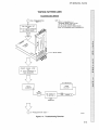
HP 16515A/16516A
1 GHz TIMING ANALYZER MODULE
Service Manual
rliDW
HEWLETT
~~ PACKARD
m
HEWLETT
PACKARD
SERVICE MANUAL
HP 16515A 1 GHz
Timing Analyzer Master Card
And
HP 16516A 1 GHz
Timing Analyzer Expansion Card
© COPYRIGHT HEWLETT·PACKARD COMPANY/COLORADO DMSION 1988
1900 GARDEN OF THE GODS ROAD, COLORADO SPRINGS, COLORADO U.S.A
ALL RIGHTS RESERVED
Manual Part No. 16515-90901
Microfiche Part No. 16515-90801
PRINTED: SEPTEMBER 1988
CERTIFICATION
Hewlett-Packard Company certifies that this product met its published specifications at the time of shipment from the factory. Hewlett-Packard further certifies that its calibration measurements are traceable to
the United States National Bureau of Standards, to the extent allowed by the Bureau's calibration faCility,
and to the calibration facilities of other International Standards Organization members.
WARRANTY
This Hewlett-Packard product is warranted against defects in material and workmanship for a period of
one year from date of shipment. During the warranty period, Hewlett-Packard Company will, at its option,
either repair or replace products which prove to be defective.
For warranty service or repair, this product must be returned to a service facility designated by HP. Buyer
shall prepay shipping charges to HP and HP shall pay shipping charges to return the product to Buyer.
However, Buyer shall pay all shipping- charges, duties, and taxes for products returned to HP from another
country.
HP warrants that its software and firmware designated by HP for use with an instrument will execute its
programming instructions when properly installed on that instrument. HP does not warrant that the operation of the instrument or software, or firmware will be uninterrupted or error free.
LIMITATION OF WARRANTY
The foregoing warranty shall not apply to defects resulting from improper or inadequate maintenance by
Buyer, buyer-supplied software or interfacing, unauthorized modification or misuse, operation outside the
environmental specifications for the product, or improper site preparation or maintenance.
NO OTHER WARRANTY IS EXPRESSED OR IMPUED. HP SPECIFICALLY DISCLAIMS THE IMPUED WARRANTIES OF MERCHANTABIUTY AND FITNESS FOR A PARTICULAR PURPOSE.
EXCLUSIVE REMEDIES
THE REMEDIES PROVIDED HEREIN ARE BUYER'S SOLE AND EXCLUSIVE REMEDIES. HP SHALL NOT
BE UABLE FOR ANY DIRECT, INDIRECT, SPECIAL, INCIDENTAL, OR CONSEQUENTIAL DAMAGES,
WHETHER BASED ON CONTRACT, TORT, OR ANY OTHER LEGAL THEORY.
ASSISTANCE
Product maintenance agreements and other customer assistance agreements are available for HewlettPackard products.
For any assistance, contact your nearest Hewlett-Packard Sales and Service Office. Addresses are
provided at the back of this manual.
CWA388
SAFETY CONSIDERATIONS
GENERAL - This is a Safety Class I instrument (provided with
terminal for protective earthing).
•
Do not install substitute parts or perform any unauthorized
modification to the instrument.
OPERATION - BEFORE APPLYING POWER verify that the
power transformer primary is matched to the available line
voltage, the correct fuse is installed, and Safety Precautions
are taken (see the following warnings). In addition, note the
instrument's external markings which are described under
"Safety Symbols.·
•
Adjustments described in the manual are performed with
power supplied to the instrument while protective covers
are removed. Energy available at many points may, if contacted, result in personal injury.
•
Any adjustment, maintenance, and repair of the opened instrument under voltage should be avoided as much as
pOSSible, and when inevitable, should be carried out only
by a skilled person who is aware of the hazard involved.
WARNING
I
•
Servicing instructions are for use by service-trained personnel. To avoid dangerous electric shock, do not perform
any servicing unless qualified to do so.
•
BEFORE SWITCHING ON THE INSTRUMENT, the protective earth terminal of the instrument must be connected to
the protective conductor of the (mains) powercord. The
mains plug shall only be inserted in a socket outlet
provided with a protective earth contact. The protective action must not be negated by the use of an extension cord
(power cable) without a protective conductor (grounding).
Grounding one conductor of a two-conductor outlet is not
sufficient protection.
=
CapaCitors inside the instrument may still be charged
even if the instrument has been disconnected from its
source of supply.
SAFETY SYMBOLS
Instruction manual symbol. The product will be
marked with this symbol when it is necessary for
the user to refer to the instruction manual in order
to protect against damage to the product.
&
!
Indicates hazardous voltages
•
•
If this instrument is to be energized via an auto-transformer (for voltage reduction) make sure the common terminal is connected to the earth terminal of the power
source.
Any interruption of the protective (grounding) conductor
(inside or outside the instrument) or disconnecting the
protective earth terminal will caus~ a potential shock
hazard that could result in personal injury.
Earth terminal (sometimes used in manual to indicate circuit common connected to grounded
chassis).
•
Whenever it is likely that the protection h~s been impaired, the instrument must be made inoperative and be
secured against any unintended operation.
•
Only fuses with the required rated current, voltage, and
specified type (normal blow, time delay, etc.) should be
used. Do not use repaired fuses or short circuited
fuseholders. To do so could cause a shock or fire hazard.
•
Do not operate the instrument in the presence of flammable gasses or fumes. Operation of any electrical instrument in such an environment constitutes a definite safety
hazard.
I
The WARNING sign denotes a hazard. It
calls attention to a procedure, practice,
or the like, which, if not correctly performed or adhered to, could result in personal injury. Do not
proceed beyond a WARNING sign until the indicated conditions are fully understood and met.
WARNING
I ?~~7T~~N,}
• ::' ~: : ~ ;; '}
The CAUTION sign denotes a hazard. It
calls
an
procedure,
practice, or the like, WhiCh, If not correctly performed or adhered to, could result in damage to or
destruction of part or all of the product. Do not proceed
beyond a CAUTION sign until the indicated conditions are
fully understood or met.
~ttention t~ op~rati~g
SC1D984
HP 16515N16A - Table of Contents
Table of Contents
SECTION I
GENERAL INFORMATION
1-1.
1-2.
1-3.
1-4.
1-5.
1-6.
1-7.
INTRODUCTION .......................................................................................................................
MODULES COVERED BY THIS MANUAL ...............................................................................
SAFETY REQUIREMENTS .......................................................................................................
PRODUCT DESCRIPTION .......................................................................................................
ACCESSORIES SUPPLIED ......................................................................................................
SPECIFICATIONS AND OPERATING CHARACTERISTICS ...................................................
RECOMMENDED TEST EQUIPMENT .....................................................................................
1-1
1-1
1-1
1-2
1-2
1-2
1-2
SECTION II
INSTALLATION
2-1.
2-2.
2-3.
2-4.
2-5.
2-6.
2-7.
2-8.
2-9.
2-10.
2-11.
2-12.
INTRODUCTION ......................................................................................................................
INITIAL INSPECTION ..............................................................................................................
PREPARATION FOR USE .......................................................................................................
POWER REqUIREMENTS ......................................................................................................
SAFETY REQUIREMENTS .. ~ ............... ~ ...................................................................................
PROBE ASSEMBLY INSTALLATION ......................................................................................
MODULE INSTALLATION .......................................................................................................
ADDING AN EXPANSION CARD ............................................................................................
OPERATING ENVIRONMENT .................................................................................................
STORAGE ................................................................................................................................
PACKAGING ............................................................................................................................
TAGGING FOR SERVICE ........................................................................................................
2-1
2-1
2-1
2-1
2-1
2-1
2-2
2-5
2-8
2-8
2-8
2-8
SECTION III
PERFORMANCE TESTS
3-1.
3-2.
3-3.
3-4.
3-5.
3-6.
3-7.
3-8.
3-9.
INTRODUCTION .......................................................................................................................
RECOMMENDED TEST EQUIPMENT .............. ~......................................................................
TEST RECORD .............................................. ...........................................................................
PERFORMANCE TEST INTERVAL ...........................................................................................
PERFORMANCE TEST PROCEDURES ...................................................................................
TEST CONNECTOR ................. ................................................................................................
MINIMUM SWING VOLTAGE TEST .........................................................................................
THRESHOLD ACCURACY TEST .............................................................................................
DYNAMIC RANGE TEST ..........................................................................................................
3-1
3-1
3-1
3-1
3-1
3-1
3-2
3-8
3-12
SECTION IV
ADJUSTMENTS
4-1. ADJUSTMENT AND CALIBRATION ......................................................................................... 4-1
iv
HP 16515A/16A - Table of Contents
SECTION V
REPLACEABLE PARTS
5-1.
5-2.
5-3.
5-4.
5-5.
5-6.
INTRODUCTION ......................•......•............•.....•.....•..............................................................•.
ABBREVIATIONS .............................•.•.....•...•..........•..•..........................•........................••...•.....
REPLACEABLE PARTS UST .......•......•....•...•...........•........••...................•..........•.......................
ORDERING INFORMATION ........................•.•....................................................................•.....
EXCHANGE ASSEMBUES ......•.........•.•.......•...........•........•.......................................................
DIRECT MAIL ORDER SYSTEM .....•..•..•......•....•..................••....•.............................•••.•............
5-1
5-1
5-1
5-1
5-1
5-2
SECTION VI
SERVICE
6-1.
6-2.
6-3.
6-4.
6-5.
6-6.
6-7.
6-8.
6-9.
v
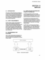
INTRODUCTION ..................................•...•.•.•.................••....•...................................•...........•....
SAFETY REQUIREMENTS ......•......•........................•....•..........................•...............•..•.............
RECOMMENDED TEST EQUIPMENT .....................................................................................
MODULE BLOCK DIAGRAM AND THEORY OF OPERATION ...............................................
SELF TESTS .............................................................................................................................
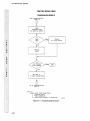
TROUBLESHOOTING ..............................................................................................................
MODULE REPLACEMENT .......................................................................................................
PROBE ASSEMBLY REPLACEMENT ....................................~.................................................
EXTENDER BOARD INSTALLATION .......................................................................................
6-1
6-1
6-1
6-1
6-4
6-9
6-28
6-31
6-35
HP 16515A/16A - Table Of Contents
LIST OF TABLES
TABLE
TITLE
1-1. HP 16515A/16A SPECIFICATIONS AND OPERATING CHARACTERISTICS ........................ 1-3
1-2. RECOMMENDED TEST EQUIPMENT ...................................................................................... 1-9
3-1. PERFORMANCE TEST RECORD ............................................................................................. 3-17
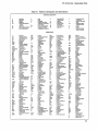
5-1. REFERENCE DESIGNATORS AND ABBREVIATIONS ............................................................ 5-3
5-2. REPLACEABLE PARTS ................................. ............................................................................ 5-5
LIST OF ILLUSTRATIONS
FIGURE TITLE
2-1.
2-2.
2-3.
2-4.
2-5.
2-6.
2-7.
2-8.
ENDPLATE OVERLAP .............................................................................................................
TIGHTENING OR LOOSENING SEQUENCE .........................................................................
ENDPLATE OVERHANG .........................................................................................................
TIGHTENING OR LOOSENING SEQUENCE .........................................................................
ENDPLATE OVERHANG .........................................................................................................
CARD ON MAT ........................................................................................................................
CABLE END .............................................................................................................................
CARDS FASTENED TOGETHER ............................................................................................
2-3
2-4
2-4
2-5
2-6
2-6
2-6
2-7
3-1.
3-2.
3-3.
3-4.
3-5.
3-6.
3-7.
3-8.
3-9.
3-10.
3-11.
3-12.
3-13.
3-14.
3-15.
3-16.
3-17.
3-18.
3-19.
3-20.
3-21.
3-22.
3-23.
3-24.
TEST CONNECTOR ................................................................................................................
EQUIPMENT SETUP TO VERIFY DC LEVELS .......................................................................
PULSE GENERATOR OUTPUT ...............................................................................................
EQUIPMENT SETUP FOR TEST .............................................................................................
STARTUP SCREEN .................................................................................................................
POD THRESHOLD FIELD IN FORMAT SCREEN ...................................................................
TRACE SCREEN ......................................................................................................................
WAVEFORMS SCREEN ..........................................................................................................
RUN-SINGLE FIELD ................................................................................................................
TEST WAVEFORMS ................................................................................................................
INPUT LABEL FIELD ...............................................................................................................
TEST EQUIPMENT SETUP .....................................................................................................
POD THRESHOLD FIELD .......................................................................................................
TRACE SCREEN ......................................................................................................................
WAVEFORM DATA ..................................................................................................................
WAVEFORM DATA ..................................................................................................................
LABEL FIELD ...........................................................................................................................
TEST EQUIPMENT SETUP .....................................................................................................
SQUARE WAVE PULSE ..........................................................................................................
POD THRESHOLD FIELD .......................................................................................................
TRACE SCREEN ......................................................................................................................
RUN-SINGLE SCREEN ...........................................................................................................
WAVEFORM DATA ..................................................................................................................
LABEL FIELD ...........................................................................................................................
3-1
3-2
3-3
3-3
3-4
3-4
3-5
3-5
3-5
3-6
3-6
3-8
3-9
3-9
3-10
3-10
3-11
3-12
3-13
3-14
3-14
3-15
3-15
3-16
vi
HP 16515A/16A - Table Of Contents
LIST OF ILLUSTRATIONS
FIGURE TITLE
vii
5-1.
PARTS IDENTIFICATION ........................................................................................................ 5-4
6-1.
6-2.
6-3.
6-4.
6-5.
6-6.
6-7.
6-8.
6-9.
6.10.
6-11.
6-12.
6-13.
6-14.
6-15.
6-16.
6-17.
6-18.
6-19.
6-20.
6-21.
6-22.
6-23.
6-24.
6-25.
6-26.
6-27.
MODULE BLOCK DIAGRAM ....................................................................................................
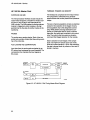
HP 16515A 1 GHZ TIMING MASTER BLOCK DIAGRAM .......................................................
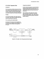
HP 16516A 1 GHZTIMING EXPANSION BLOCK DIAGRAM ................................................
STARTUP SCREEN .................................................................................................................
LOAD TEST SYSTEM ..............................................................................................................
TEST SYSTEM SCREEN .........................................................................................................
MAIN TEST MENU ...................................................................................................................
FANOUT TEST RUN SCREEN ................................................................................................
STOP FIELD .............................................................................................................................
EXIT TEST SYSTEM ................................................................................................................
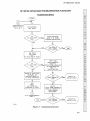
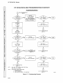
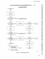
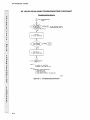
TROUBLESHOOTING FLOWCHART ....................................................................................
TIGHTENING OR LOOSENING SEQUENCE ........................................................................
ENDPLATE OVERHANG ........................................................................................................
SCREW REMOVAL .................................................................................................................
CABLE POSITION ..................................................................................................................
TIGHTENING OR LOOSENING SEQUENCE ........................................................................
ENDPLATE OVERHANG .........................................................................................................
TIGHTENING OR LOOSENING SEQUENCE ........................................................................
ENDPLATE OVERHANG ........................................................................................................
CABLE POSITION ..................................................................................................................
SCREW REMOVAL .................................................................................................................
CABLE AND RETAINER REMOVAL .......................................................................................
TIGHTENING OR LOOSENING SEQUENCE ........................................................................
ENDPLATE OVERHANG ........................................................................................................
CABLE POSITION ..................................................................................................................
SCREW REMOVAL .................................................................................................................
INSTALLATION SUMMARY ....................................................................................................
6-1
6-2
6-3
6-4
6-5
6-5
6-6
6-6
6-7
6-7
6-10
6-28
6-29
6-29
6-30
6-30
6-30
6-31
6-32
6-32
6-33
6-34
6-35
6-36
6-36
6-37
6-37
TABLE OF CONTENTS
GENERAL INFORMATION
1-1.
1-2.
1-3.
1-4.
1-5.
1-6.
1-7.
Introduction ......................................................................................................................... 1-1
Modules Covered By Manual .............................................................................................. 1-1
Safety Requirements ............... ........................ ..................................................................... 1-1
Product Description ............................................................................................................. 1-2
Accessories Supplied ................................................~......................................................... 1-2
Specifications And Operating characteristics .................................................................... 1-2
Recommended Test Equipment ......................................................................................... 1-2
HP 16515A/16A - General Information
SECTION I
GENERAL INFORMATION
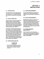
1·1. INTRODUCTION
This service manual contains information for testing and servicing the HP 16515A/16A 1 GHz
Timing Analyzer Module. Also included are installation procedures and a list of recommended test
equipment.
.
This manual Is divided into six sections as follows:
I - General Information
II - Installation
III - Performance Tests
IV - Adjustments
V - Replaceable Parts
VI - Service
Information for operating, programming, and interfacing the HP 16515A/16A 1 GHz Timing Analyzer
Module is contained in the HP 16515A/16A 1 GHz
Timing Analyzer Operating and Programming
Manual supplied with each module.
The General Information Section includes safety requirements, a product description, and a list of accessories supplied. Also included are tables listing
specifications and operating characteristics, and a
list of recommended test equipment.
Usted on the title page of this manual is a
Microfiche part number. This number can be used
to order 4 X 6 inch microfilm transparencies of the
manual. Each microfiche contains up to 96 photoduplicates of the manual pages. The microfiche
package also includes the latest Manual Changes
supplement as well as pertinent Service Notes.
To complete the service documentation for your
system, place this service manual in the 3-ring
binder with your Logic Analysis System Service
Manual.
1·2. MODULES COVERED BY THIS
MANUAL
The information covered in this manual is for the
HP 16515A/16A 1 GHz Timing Analyzer Module. If
either card has changed, a new card number will
be assigned and the manual will be accompanied
by a Manual Changes Supplement. This supplement explains the changes and how to adapt the
manual to the newer card.
In addition to the change information, the supplement may contain information for correcting errors
in the manual. To keep this manual as current and
accurate as possible, Hewlett-Packard recommends that you periodically request the latest
Manual Changes Supplement.
1·3. SAFETY REQUIREMENTS
Specific warnings, cautions, and instructions are
placed wherever applicable throughout the
manual. These must be observed during all phases
of operation, service, and repair of the module.
Failure to comply with them violates safety standards of design, manufacture, and intended use of
this module. Hewlett-Packard assumes no liability
for the failure of the customer to comply with these
safety requirements.
1-1
HP 16515A/16A - General Information
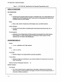
1-4. PRODUCT DESCRIPTION
The HP 16515A/16A 1 GHz Timing Analyzer
Module is a high speed timing analyzer with a minimum configuration of 16 channels and is expandable to 32 channels when a HP 16516A Expansion Card is added. The module has passive probIng, intermodule triggering and arming capabilities.
Some of the main features are:
• 1 GHz timing, providing up to 1 ns single shot
resolution.
HP 16516A:
• Probe Lead Set Kit (HP 16515-69502) Qty 2
• Probe Assembly (HP 16515-61604) Qty 16
• Grabbers, Set of 20 (HP 5959-0288) Qty 2
• Intercard Connect Cable (HP 16516-61601)
• Screws M3 X 0.5 (HP 0515-1246) Qty 6
• Label Set (HP 16500-94303)
• 16 channels per HP 16515A Master Card, 16
channels per HP 16516A Expansion Card,
and a maximum of 80 channels per HP
16500A.
• 8 Kbits memory per channel.
• Pattern, pattern duration, edge, arm trigger
between modules via Intermodule Bus.
• Small lightweight .probing.
1-6. SPECIFICATIONS AND
OPERATING CHARACTERISTICS
Module specifications and operating characteristics are listed in Table 1-1. Specifications are the
performance standards against which the module
is tested.
The operating characteristics are not specifications, but are typical operating characteristics included as additional information for the user.
1-5. ACCESSORIES SUPPLIED
The following accessories are supplied with the HP
16515A/16A 1 GHz Timing Analyzer Module. Quantity one unless shown otherwise.
HP 16515A:
• Operating manual set
• Service manual
• Probe Lead Set Kit (HP 16515-69502) Qty 2
• Probe Assembly (HP 16515-61604) Qty 16
• Grabbers, Set of 20 (HP 5959-0288) Qty 2
• Label Set (HP 16500-94303)
1-2
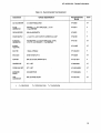
1·7. RECOMMENDED TEST
EQUIPMENT
Equipment required to test and maintain the HP
16515A/16A 1 GHz Timing Analyzer Module is
listed in table 1-2. Other equipment may be substituted if it meets or exceeds the critical specifications listed in the table.
HP 1651SA/16A - General Information
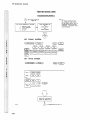
Table 1-1. HP 16515A/16A Specifications And Operating Characteristics
HP 16515A/16A SPECIFICATIONS
PROBES
Minimum Swing:
• SOD mV peak-to-peak.
Threshold Accuracy:
.•
± 1S0 mV ± 3.0% over the range 0 volts to + 5 volts.
± 1S0 mV ± 2.0% over the range -3.S volts to 0 volts.
Dynamic Range:
•
± 7.0 volts
HP 16515A/16A OPERATING CHARACTERISTICS
PROBES
Input RC:
• 10 kn ± 2% shunted by approximately 3 pF at the probe tip.
Minimum Input Overdrive:
• 250 mV or 30% of the input amplitude, whichever is greater, above the pod threshold.
Maximum Input Voltage:
•
± 40 volts.
Threshold setting:
• Threshold levels may be defined for each pod individually.
Threshold Range:
• - 3.5 to + 5.0 volts in 0.1 volt increments.
TIL Threshold Preset:
• + 1.S volts.
Eel Threshold Preset:
• -1.3 volts.
1-3
HP 16515A/16A - General Information
Table 1-1. HP 16515A/16A Specifications And Operating Characteristics (cont.).
ACQUISITION MEMORY
Memory Depth:
• 8192 samples/channel.
Data Channels:
• 2 eight channel pods (16515A).
4 eight channel pods (16515A/16516A).
Sample Period:
• 1 ns to 1.6 ms dependent on s/Div and delay settings.
TIME INTERVAL ACCURACY •
Timebase Accuracy:
•
± 0.01 % of the time interval reading plus:
± 500 ps at 250 MHz to 1 GHz sample rate.
± 2 ns s 125 MHz sample rate.
Time Interval Accuracy:
•
± Sample Period ± Timebase Accuracy ± (2 ns within pod or 2.5 ns between pods)
TRIGGER
Asynchronous Pattern:
•
• Trigger on an asynchronous pattern less than or greater than specified duration, or trigger
on a not-equal-to pattern greater than the specified duration. Pattern is the logical AND of
specified Low, High, or Don't Care for each assigned channel. If pattern is valid but duration is
invalid, there is a 2.6 ns reset time before the instrument is ready to look for the pattern again.
Greater Than Duration:
• Trigger occurs at pattern valid followed by duration expired.
1-4
HP 16515A/16A - General Information
Table 1-1. HP 16515A/16A Specifications And Operating Characteristics (cant.)
Range:
• 2 ns to 507 sample periods for patterns specified within a pod.
7 ns to 507 sample periods for patterns specified across pods on the same board.
10 ns to 507 sample periods for patterns specified across boards (16515A and 16516A) within
a module.
Resolution:
• 4 sample periods.
Accuracy:
• *
± 2 ns (2 ns setting)
± 1 sample period ± :
2 ns for patterns specified within a pod.
6 ns specified across pods on the same board.
8 ns specified across boards within a module.
(for all other settings)
Less Than Duration:
• * Trigger occurs at the end of the pattern. Patterns specified within a pod must be valid for at
least 1.5 ns. Patterns specified across pods on same board must be valid for at least 11 ns.
Patterns may not be specified across boards (16515A116516A).
Range:
• 16 ns to 507 sample periods for patterns specified within a pod.
20 ns to 507 sample periods for patterns specified across pods on same board.
Resolution:
• 4 sample periods.
Accuracy:
• *
± 1 sample period ± :
3 ns for patterns specified within a pod and 7 ns for patterns specified across pods on same
board.
Edge Trigger:
• Trigger on edge following valid duration of asynchronous pattern. Trigger is the OR of specified
rising or falling edges. Less than duration forces edge triggering off.
• * Minimum pulse width:
1.5 ns.
Delay From Trigger To BNC Output Port:
• * Less than 50 ns from the probe tip.
1,.5
HP 16515A!16A - General Information
Table 1-1. HP 16515A/16A Specifications And Operating Characteristics (cant.).
DISPLAY FUNCTIONS
Data Display/Entry.
Labels
• Channels may be grouped together and given a 6 character name. Up to twenty labels may be
assigned with up to 32 channels per label. Primary use is for naming groups of channels such
as address, data, and control busses.
Bases:
• Binary, Octal, Decimal, Hexadecimal, ASCII (display only), user-defined symbols.
Activity Indicators:
• Provided in the Format Menu for identifying the current state of input lines as high, low, or
changing.
Timing Waveform:
• Interleaved, time-correlated listing of timing waveforms and waveforms from other measurement modules (I.e., another timing analyzer or oscilloscope). Pattern readout of timing
waveform at X or 0 marker in the selected base. .
WAVEFORM DISPLAY
Sec/div:
• 1 ns to 1 s adjustable, with 3 digit resolution.
Delay:
e
-12.5 s to+53.5 ks.
Accumulate:
• Waveform display is not erased between successive acquisitions.
Overlay Mode:
• Multiple channels can be displayed on one waveform display line. Primary use is to view summary of bus activity.
Maximum Number Of Displayed Waveforms:
24
Marker Functions
Time Interval:
• The X and 0 markers,shown as dashed lines on the display, measures the time interval between one point on a timing waveform and trigger, two points on the same timing waveform, or
two points on different waveforms.
1-6
HP 16515A/16A - General Information
Table 1-1. HP 16515A/16A Specifications And Operating Characteristics (cont.)
Patterns:
• The X and 0 markers can be used to locate the a to 8192 occurrence of a specified pattern
before or after trigger. The 0 marker can also be used to locate the a to 8192 occurrences of a
pattern before or after the X marker.
Statistics:
• X to 0 marker statistics are calculated for repetitive acquisitions. Patterns must be specified for
both markers, and statistics are updated only when both patterns can be found in an acquisition. Statistics are minimum X to 0 time, maximum X to 0 time, average X to 0 time, and count
of valid runs and total runs.
Trigger:
• Displayed as a vertical dashed line in the timing waveform display. Actual location of trigger in
memory may vary from marker by ± 4 samples (16515A) and ± 6 samples (16515A/16516A).
ACQUISITION FUNCTIONS
Run:
• Starts acquisition of data in specified trace mode. Single mode acquires data once while repetitive mode repeats single mode acquisitions until STOP is touched or until time interval between
two specified patterns is less than or greater than a specified value, or within or outside a
specified range.
Stop:
• In single trace mode, or the first run of a repetitive acquisition, STOP halts acquisition and displays the current acquisition data. ·For subsequent runs in repetitive mode, STOP halts acquisition of data and does not change current display.
Arming:
• By the Run Field or from any other module or the external port-in via the Intermodule Bus.
*
These characteristics are true for input signal, VH
volts, slew rate = 1 V/ns.
= -0.90 volts, VL = -1.70 volts, threshold = -1.3
1-7
HP 16515A/16A - General Information
Table 1-1. HP 16515A/16A Specifications And Operating Characteristics (cont.)
OPERATING ENVIRON"MENT
Temperature:
• Instrument, 00 to 550 C (+320 to 131 0 F).
Probe lead sets and cables, 00 to 65 0 C (+3~ to 14go F).
Humidity:
• Instrument, up to 95% relative humidity at +400 C (+ 1040 F).
Altitude:
• To 4600 m (15,000 ft).
Vibration
Operating:
• Random vibration 5-500 Hz, 10 minutes per axis,
'V
0.3 g (rms).
Non-operating:
• Random vibration 5-500 Hz, 10 minutes per axis, 2.41 g (rms); and swept sine resonant
search, 5-500 Hz, 0.75 g (O-peak), 5 minute resonant dwell @ 4 resonances per axis.
'V
1-8
HP 16515A/16A - General Information
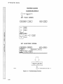
Table 1-2. Recommended Test Equipment
Critical Specification
Instrument
Recommended
Model
Use*
DC VOLTMENTER
3 1/2 DIGIT RESOLUTION
HP3468A
P,T
PULSE
GENERATOR
RINGING S ± 10 % AMPUTUDE ± 10 mV
1.3 J.LS RISETIME
HP 8161A
P
OSCIU.OSCOPE
300 MHz BANDWIDTH
HP 54201
T
POWER SUPPLY
+ 5.30 V TO • 3.72 V OUTPUT; CURRENT 0-0.4 AMP
HP 6216B
P
FUNCTION
GENERATOR
SCUARE WAVE ± 7 VOLTS AMPUTUDE; 10 MHz
+ 5 V TO • 3.5 V OFFSET; < 7 ns RISETIME
HP 8116A
P,T
HP 10100C
P,T
50 OHM
FEEDTHRU
BNCTEE
1 MALE, 2 FEMALE
HP 1250-0781
P
BNCCable
(M-M) 48 INCH CTY 2
HP 10503A
P,T
ADAPTER
BNC (F) TO DUAL BANANA CTY 2
HP 1251·2277
P
GRABBER SET
CTY 1 SET
HP 5959-0288
P,T
PROBE LEAD SET
CTY 1 SET
HP 16515-69502
P,T
EXTENDER
BOARD
NO SUBSTITUTE
HP 16500-69004
T
TEST
CONNECTOR
BNC (F) PANEL MOUNT
HP 1250-1032
P,T
*
A
= Adjustments
P
= Performance Tests
T
= Troubleshooting
1-9
TABLE OF CONTENTS
INSTALLATION
2-1.
2-2.
2-3.
2-4.
2-5.
2-6.
2-7.
2-8.
2-9.
2-10.
2-11.
2-12.
Introduction ......................................................................................................................... 2-1
Initial Inspection ................................................................................................................... 2-1
Preparation For Use ............................................................................................................ 2-1
Power Requirements .......................................................................................................... 2-1
Safety Requirements ............................................................................................................ 2-1
Probe Assembly Installation ............................................................................................... 2-1
Module Installation .............................................................................................................. 2-2
Adding An Expansion Card ................................................................................................ 2-5
Operating Environment ...................................................................................................... 2-8
Storage ................................................................................................................................ 2-8
Packaging ........................................................................................................................... 2-8
Tagging For Service ........................................................................................................... 2-8
HP 16515A/16A -Installation
SECTION II
INSTALLATION
2-1. INTRODUCTION
2-4. POWER REQUIREMENTS
This section explains, how to initially inspect the
HP 16515A/16A 1 GHz Timing Analyzer Module,
how to prepare it for use, storage and shipment.
Also included are procedures for module installation.
All power supplies required for operating the HP
16515A/16A 1 GHz Timing Analyzer Module are
supplied to the module through the backplane connector.
2-5. SAFETY REQUIREMENTS
2-2. INITIAL INSPECTION
Inspect the shipping container for damage. If the
'shipping container or cushioning material is
damaged, it should be kept until the contents of
the shipment have been checked for completeness and the module has been checked mechanically and electrically. The'contents of the. shipment
should be as listed in the "ACCESSORIES SUPPLlED" paragraph located in Section I.
Procedures for checking electrical performance
are in Section III. If the contents of the container
are incomplete, there is mechanical damage or
defect, or the instrument does not pass the performance tests, notify the nearest Hewlett-Packard office. If the shipping container is damaged, or the
cushioning material shows signs of stress, notify
the carrier as well as the Hewlett-Packard office.
Keep the shipping material so the carrier can inspect it. The Hewlett-Packard office will arrange for
repair or replacement at Hewlett-Packard's option
without waiting for claim settlement.
Specific warnings, cautions, and instructions are
placed wherever applicable throughout the
manual. These must be observed during all phases
of operation, service, and repair of the module.
Failure to comply with them violates safety standards of design, manufacture, and intended use of
this module. Hewlett-Packard assumes no liability
for the failure of the customer to comply with these
safety requirements.
2-6. PROBE ASSEMBLV
INSTALLATION
The HP 16515A/16A 1 GHz Timing Analyzer
Module comes with probe assemblies installed by
the factory. If a probe assembly is to be replaced,
refer to "PROBE ASSEMBLY REPLACEMENT" in
Section VI of this manual.
2-3. PREPARATION FOR USE
I WARNING
I
Read the Safety Considerations in the front
of this manual and the Safety Requirements
in Section I before installing or operating
this module.
2-1
HP 16515A/16A -Installation
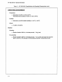
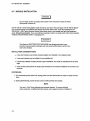
2-7. MODULE INSTALLATION
WARNING
I
Do not install, remove or replace the module in the instrument unless the instrument power is turned off.
The HP 16515A 1 GHz Timing Master Card will take up one slot in the card cage. The HP 16516A Expansion Card will require one additional slot directly above the master card. If you are installing the HP
16515A/16A 1 GHz Timing Analyzer Module (one master card or one master card and one expansion
card), follow this procedure. If you are adding an expansion card to a master card, follow the procedure
IIADDING AN EXPANSION CARDII in paragraph 2-8.
The effects of ELECTROSTATIC DISCHARGE can damage electronic components. Use grounded wriststraps and mats when performing any kind of service to this module.
INSTALLATION CONSIDERATIONS:
• A two card module must remain screwed together and installed in two adjacent slots.
• A one card module may be installed in any available slot.
• If previously installed modules prevent proper installation, they must be repositioned in the card
cage.
• Cards or filler panels below the empty slots intended for the module installation do not have to be
removed.
PROCEDURE:
1. Turn instrument power switch off, unplug power cord and disconnect any input or output connections.
2. Starting from the top, loosen thumb screws on filler panel(s) and card(s).
Note
Two card 1 GHz Timing Modules are screwed together. To prevent binding
when loosening or tightening thumb screws, use sequence shown in figure 2-2.
2-2
HP 16515N16A -Installation
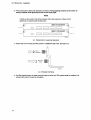
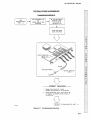
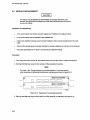
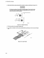
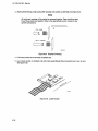
3. Starting from the top, begin pulling card(s) and filler panel(s) out half way. See figure 2-1.
All multi-card modules will be cabled or screwed together. Care should be taken
to pull these cards out together. Refer to the appropriate service books for any
specific precautions during installation.
TOP CARD
¢=J1
NEXT LOWEST
<
12
16530/EX13
2-1. Endplate Overhang
4. If the module consists of one master card, this card can be installed in any available slot. If the
module consists of two cards, pick two adjacent slots. Remove the filler panel(s).
5. Slide card (5) approximately half way into the slot(s) that you are using for this installation.
2-3
HP 16515A/16A -Installation
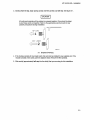
6. Firmly seat bottom card(s) into backplane connector. Keep applying pressure to the center of
card(~) end plate while tightening thumb screws finger tight.
Note
If there are two cards in the timing module, follow the sequence in figure 2-2 for
tightening or loosening the thumbscrews.
I~ 15516"
4
o
I
~~I ~I__~I ~I__~I ~I__~
I~HI515A
o
lCHz nlo4INC EXP"NSION
3
lGHz TIMING WASTER
I
2
L-..-----JI ''-__---II IL-..-----JI ,-I__---I
15515/EX3'1
2-2. Tightening Or Loosening Sequence
7. Repeat step 6 for all cards and filler panels in a bottom to top order. See figure 2-3.
NEXT
HIGHEST
BOTTOM
CARD
'8530/EXI5
2-3. Endplate Overhang
8. Any filler panels that are not used should be kept for future use. Filler panels must be installed in all
unused card slots for correct air circulation.
2-4
HP 16515N16A -Installation
2-8. ADDING AN EXPANSION CARD
This procedure should be used if you are adding an HP 16516A 1 GHz Timing Analyzer Expansion Card to
a previously installed HP 16515A 1 GHz Timing Analyzer Master Card.
The effects of ELECTROSTA TIC DISCHARGE can damage electronic components. Use grounded wrists traps and mats when performing any kind of service to this module.
INSTALLATION CONSIDERATIONS:
• Cards must be screwed together and installed in two adjacent slots.
• If previously installed modules prevent proper installation, they must be repositioned in the card
cage.
• Cards or filler panels below the empty slots intended for the module installation do not have to be
removed.
PROCEDURE:
1. Turn instrument power switch off, unplug power cord and disconnect any input or output connections.
2. Starting from the top, loosen thumb screws on filler panel(s) and card(s).
Note
Two card 1 GHz Timing Modules are screwed together. To prevent binding
when loosening or tightening thumb screws, use sequence shown in figure
1~ 165'S"
4
D
~~II~
~~I ~I
I
__~I ~I__~I ~I__~
1@eJ15515"
D
lCHz TIMING EXPANSION
2-4.
3
10Hz TIIoIING WASTER
I
__~I ~I__~I ~I__~
2
16515/EX3~
2-4. Tightening Or Loosening Sequence
3. Starting from the top, begin pulling card(s) and filler panel(s) out half way. See figure 2-5.
2-5
HP 16515A/16A -Installation
All multi-card modules will be cabled or screwed together. Care should be taken
to pull these cards out together. Refer to the appropriate service books for any
specific precautions during installation.
TOP CARD
¢Jl
NEXT LOWEST
16530/£XI3
2-5. Endplate Overhang
4. Pull the timing analyzer master card completely out.
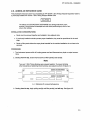
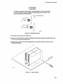
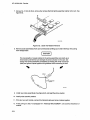
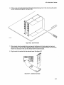
5. Lay timing analyzer master card on an antistatic mat. See figure 2-6.
6. Connect intercard cable to the timing analyzer master card making sure to use the correct cable
end. See figure 2-7.
& KEY
ON SAME SIDE
CABLE
16515/£XZ9
2-6. Card On Mat
2-6
2-7. Cable End
HP 16515N16A -Installation
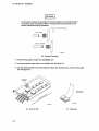
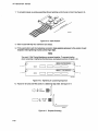
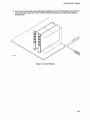
7. Fasten the timing analyzer expansion card to the timing analyzer master card using a No.1 0 torx ®
driver and the six (6) screws furnished with the timing analyzer expansion card. See figure 2-8.
2-8. Cards Fastened Together
8. Connect other end of intercard cable to expansion card.
9. Go to step 4 of paragraph 2-7, "MODULE INSTALLATION", and continue from that point.
2-7
HP 16515N16A -Installation
2·9. OPERATING ENVIRONMENT
The operating environment is listed in table 1-1.
. Note the non-condensing humidity limitation. Condensation within the instrument can cause poor
operation or malfunction. Protection should be
provided against internal condensation. The HP
16515N16A will operate at all specifications within
the temperature and humidity range given in table
1-1. However, reliability is enhanced by operating
the instrument within the following ranges.
2-11. PACKAGING
Follow these general instructions for repacking the
module with commercially available materials .
• Wrap module in anti-static plastic.
•
Use a strong shipping container. A doublewall carton made of 350 lb. test material is
adequate.
•
Use a layer of shock-absorbing material 70-to100 mm (3-to- 4 inch) thick around all sides of
the module to provide firm cushioning and
prevent movement inside the container.
•
Seal shipping container securely.
•
Mark shipping container FRAGILE to ensure
careful handling.
•
In any correspondence, refer to module by
model number and board number.
• Temperature: +200 to +35 0 C (+68° to
+95 0 F)
•
Humidity: 20% to 80% non-condensing
2·10. STORAGE
The module may be stored or shipped in environments within the following limits:
• Temperature: -40 0 C to + 75 0 C
•
Humidity: Up to 90% at 65 0 C
2·12. TAGGING FOR SERVICE
•
Altitude: Up to 15,300 meters (50,000 Feet)
If the module is to be shipped to a Hewlett-Packard office for service or repair, attach a tag with
your name and address, the complete board number, and a description of the service required.
The module should also be protected from
temperature extremes, which cause condensation
on the module.
2-8
TABLE OF CONTENTS
PERFORMANCE TESTS
3-1.
3-2.
3-3.
3-4.
3-5.
3-6.
3-7.
3-8.
3-9.
Introduction .......................................................................................................................... 3-1
Recommended Test Equipment ......................................................................................... 3-1
Test Record .......................................................................................................................... 3-1
Performance Test Interval .......... ~ ........................................................................................ 3-1
Performance Test Procedures ............................................................................................ 3-1
Test Connector .................................................................................................................... 3-1
Minimum Swing Voltage Test .............................................................................................. 3-2
Threshold Accuracy Test ..................................................................................................... 3-8
Dynamic Range Test .................................
3-12
0 .........................................................................
HP 16515A/16A - Performance Tests
SECTION III
PERFORMANCE TESTS
3-1. INTRODUCTION
The procedures in this section test the HP
16515A/16A 1 GHz Timing Analyser's electrical performance using the specifications listed in Section
I as the performance standards. All tests can be
performed without access to the interior of the instrument. At the end of this section is a form that
can be used as a record of performance test
results.
3-2. RECOMMENDED TEST
EQUIPMENT
Equipment recommended for performance tests is
listed in table 1-2. Any equipment that satisfies the
critical specifications given in the table may be substituted for the recommended models.
3-3. TEST RECORD
Results of performance tests may be tabulated on
. the Performance Test Record (table 3-1) at the end
of the procedures. The test record lists all of the
tested specifications and their acceptable limits.
The results recorded on the test record may be
used for comparison in periodic maintenance and
troubleshooting or after repairs have been made.
3-5. PERFORMANCE TEST
PROCEDURES
All performance tests should be performed at the
instruments environmental operating temperature
and after a 15-minute warm up period.
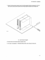
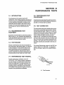
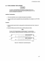
3-6. TEST CONNECTOR
The performance tests and troubleshooting procedures require connecting pulse generator outputs
to probe assembly inputs. Figure 3-1 is a test connector that may be built to allow testing of multiple
channels (up to eight at one time). The test connector consists of a BNC connector and two
lengths of wire. Connecting more than eight channels to the test connector at a time will induce loading of the circuit and true signal representation will
degrade. Test results may not be accurate if more
than eight channels are connected to the test connector.
The Hewlett-Packard part number for the BNC connector in figure 3-1 is 1250-1032. An equivalent
part may be used in place of the Hewlett-Packard
part.
3-4. PERFORMANCE TEST INTERVAL
Periodic performance verification of the HP
16515A/16A 1 GHz Timing Analyzer is required at
two year intervals. The instrument's performance
should be verified after it has been serviced, or if
improper operation is suspected. Further checks
requiring access to the interior of the instrument
are included in the adjustment section, but are not
required for the performance verification.
16510/EX07
3-1. Test Connector
3-1
HP 16515A/16A - Performance Tests
3·7. Minimum Swing Voltage Test
Description:
This test verifies the minimum swing voltage specification of the input probes and probe hybrid of the HP
16515A and HP 16516A. A square wave input will swing about an ECL level with a precise amplitude of
500 mY. A visual account of approximately one pulse per division with no missing pulses indicates a
passed test. One probe (8 channels) is tested at a time.
Specification:
Minimum Swing: 500 mV peak to peak.
Equipment:
Pulse Generator................................................................................................................................... HP 8161A
DC Voltmeter ....................................................................................................................................... HP 3468A
50 Ohm Feedthru ................................................................................................................................ HP 101 OOC
BNC Tee ............................................................................................................................................... HP 1250-0781
BNC Cable (2) ...................................................................................................................................... HP 10503A
Adapter ................................................................................................................................................ HP 1251-2277
Test Connector see figure 3-1
Procedure:
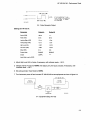
1. Connect the HP 16515A/16A to test eqUipment as shown in figure 3-2.
Note
In this setup, eight channels are connected. All ground leads must be grounded
to ensure accurate test results.
HP 16515A/16A
DC
VOLTMETER
PULSE
GENERATOR
TIMING
ANALYZER
A
,1
1
500
FEEDTHRU
.~
8NC
TEE
SEE
FIG 3-1
8
8
TEST
CONNECTOR
3-2. Equipment Setup To Verify DC Levels
2. Turn instrument power on.
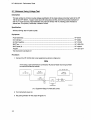
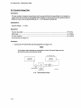
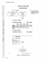
3. Set pulse generator for the output in figure 3-3.
3-2
-...,
GND
DATA
16515/BL 11
HP 16515N16A - Performance Tests
OY-----------------------------~ 50NS ~
-1.05Y-----------} NOTE:
-1.55Y-----------~100NS~
IT IS IMPORTANT THAT
THIS PULSE IS ADJUSTED
TO AS CLOSE TO 500MY
AS POSSIBLE.
3-3. Pulse Generator Output
Settings for HP 8161A:
Parameter
Output A
Output B
Period (PER)
100 ns
Width (WID)
SOns
SOns
Leading Edge (LEE)
1.3 ns
1.3 ns
Trailing Edge (TRE)
1.3 ns
1.3 ns
High Level (HIL)
-1.05 V
-1.05 V
Low Level (LOL)
-1.55 V
-1.55 V
Delay (DEL)
Ons
Ons
Output Mode
ENABLE
DISABLE
Output
COMPL
Input Mode is set to GATE.
4. Adjust High Level (HIL) of pulse, if necessary, until voltmeter reads - 1.05
v.
5. Change channel A output to NORM, then adjust Low Level (LOL) of pulse, if necessary, until
voltmeter reads - 1.55 v.
6. Set pulse generator Input Mode to NORM.
7. Turn instrument power off and connect HP 16515N16A to test equipment as shown in figure 3-4.
HP 16?15A/16A
PULSE
GENERATOR
TIMING
ANALYZER
A
500
FEEDTHRU
SEE
FIG 3-1
8
8
TEST
CONNECTOR
GND
DATA
16515/BL09
3-4. Equipment Setup For Test
3-3
HP 16515N16A - Performance Tests
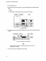
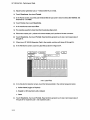
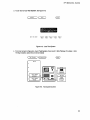
8. Turn instrument power on.
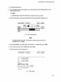
9. From the startup screen shown in figure 3-5, touch the following fields in the ordered sequence
below:
a. System
b. 1 GHz Timing (If multiple timing modules, select the one to be tested.)
System
) (Conf 19uratton)
Cards
A
-
---
B
Iiiiiii:I
C
•
I
GHz TIMING
EXPANDER
I
GHz TIMING
MASTER
D
Iiiiiii:I
RS-232C
U
Pr1nter
3-5. Startup Screen
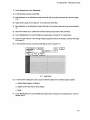
10. In the Format screen, touch pod threshold field as shown in figure 3-6, then touch EeL. Repeat for
all pods.
(
I
GHz Tlm1ng E) (
~ (
Format
Run
3-6. Pod Threshold Field In Format Screen
Note
The labels default to A and B. For illustration purposes, these were set to A =
MASTER and B = EXPNDR.
11. From the Format screen touch Format, then touch Trace.
3-4
HP 16515N16A - Performance Tests
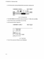
12. Set Trace screen as shown In figure 3-7.
I GHz Timing E)
Trace
Lobel >
( MASTER) ( EXPNDR )
Bose >
~~
Find
Pattern
Equal
Then find
Edge
Run
e§]e§]
present for ~
(
3 ns )
c=Jc=J
3-7. Trace Screen
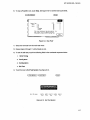
13. From the Trace screen, touch Trace, then touch Waveforms.
14. In the Waveforms screen, shown in figure 3-8, set the s/Div to 100 ns.
I GHz Timing E )
Hoyeforms
EJ (
Run
3-8. Waveforms Screen
15. Touch Run, then drag finger to Single. See figure 3-9.
I GHz Timi ng E)
Hoyef arms
~~
3-9. Run-Single Field
3-5
HP 16515A/16A - Performance Tests
16. The resulting waveforms should look like figure 3-10. Adjust the delay to line up pulse edge with center screen graticule. There should be approximately 1 pulse per division with no missing pulses.
(
1 GHz Timing E) (
( Accumu Ie te
Off
(
s/Dlv
100 ns
Heveforms
J
~
)
J{
De ley
o
s
J(
Merleers
Of f
Run
I
I ns
IsemPle perlod •
{
J
MASTER 0
MASTER 1
MASTER 2
MASTER 3
MASTER ~
MASTER 5
MASTER e
MASTER 7
MASTER e
MASTER 9
MASTER 10
MASTER I I
MASTERI2
MASTER 13
:
:
:
:
MASTERI~
MASTER 15
:
3-10. Test Waveforms
17. Disconnect probe assemblies from master pod 1 and connect master pod 2.
18. Repeat steps 15 and 16 for pod 2 probe assemblies.
19. If there is an H~ 16516A 1 GHz Timing Analyzer Expansion Card in the module, continue with steps
20 through 23.
20. In the Waveforms screen touch the input Label field as shown in figure 3-11.
(
I GHz Timi ng E) (
Accumu Ie te
Off
s/Dlv ]
100 ns
1
f
~
)
I ns
IsemPle perlod •
Deley
o
r--
1-
Heve10rms
s
1
r--
'--
Merleers
011
r--
---
J
r--
'--
r-
r--
'--
~
r--
'--
:
:
:
:
:
3-11. Input Label Field
3-6
(
I
r--
'--
Run
r--
'--
r--
'--
HP 16515A/16A - Performance Tests
21. In the Waveforms screen touch the following fields in the ordered sequence below:
a. Action Insert (toggles to Replace)
b. EXPNDR (or 8 if labels are left at default)
c. Done
Note
The labels default to A and B. For illustration purposes, these were set to A
MASTER and B = EXPNDR.
=
22. Connect expander pod 1 probe assemblies and repeat steps 15 and 16.
23. Connect expander pod 2 probe assemblies and repeat steps 15 and 16.
3-7
HP 16515A/16A - Performance Tests
3-8. Threshold Accuracy Test
Description:
This test verifies the threshold accuracy within the two ranges stated in the specification. Threshold
levels set at specified limits are applied. A passed test will show the correct logic state for the dc level
input with respect to the programmed threshold. One pod (8 channels) is tested at a time.
Specification:
± 150 mV ± 3.0% over the range of 0 V to + 5 V.
± 150 mV ± 2.0% over the range - 3.5 V to 0 V.
Equipment:
Power Supply ...................................................................................................................................... HP 62168
DC Voltmeter ....................................................................................................................................... HP 3468A
8NC Tee ............................................................................................................................................... HP 1250-0781
Adapter (2) ........................................................................................................................................... HP 1251-2277
BNC Cable (2) ...................................................................................................................................... HP 10503A
Test Connector see figure 3-1
Procedure:
1. Connect the HP 16515A/16A and test equipment as in figure 3- ~ 2.
Note
In this setup, eight channels are connected at a time. All ground leads must be
grounded to ensure accurate test results.
HP 16515A/16A
DC
VOLTMETER
POWER
SUPPLY
TIMING
ANALYZER
...JL
-BNC
TEE
SEE
FIG 3-1
TEST
CONNECTOR
3-12. Test Equipment Setup
3-8
8
8
~
GND
DATA
16515/BL 10
HP 16515N16A - Performance Tests
2. Turn instrument power on.
3. From the startup screen shown in figure 3-5 of previous test, touch the following fields in the ordered sequence below:
a. System
b. 1 GHz Timing (If multiple HP 16515N16A modules, pick the one to test.)
4. In the Format screen, touch pod threshold field for the pod under test. See figure 3-13.
1 GHz Timing E) (
~
Formot
(
Run
3-13. Pod Threshold Field
Note
The labels default to A and B. For illustration purposes, these were set to A =
MASTER and B = EXPNDR.
5. Touch User Defined and using keypad, set threshold to
+ 5 Volts, then touch DONE.
6. From the Format screen, touch Format, then touch Trace.
7. Set Trace screen as shown in figure 3-14.
(
1 GHz Timl ng E) (
~
Troce
Lobe I )
( MASTER) ( EXPNDR )
60se )
~~
(
Run
Find
Po ttern
I(
Equo I
~~
present for
Then find
Edge
0
(
3 ns )
c:Jc:J
3-14. Trace Screen
3-9
HP 16515N16A - Performance Tests
8. From the Trace screen touch Trace, then touch Waveforms.
9. In the Waveforms screen set the s/Div to 50 ns.
10. Set power supply to output
+ 5.30 Volts.
11. Touch Run then drag finger to Single.
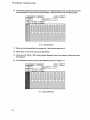
12. Data displayed on Waveforms screen will be all high for probes under test. See fjgure 3-15.
(
I GHz Tlmlng E
Accumu Ie te
Off
s/Dly
50 ns
J(
Heyeforms
J
J(
~
)
IsemPle period·
Deley
o
I ns
(
Run
I
) ( Merkers )
s
Off
MA::ilc!< Ii
MASTER I
MASTER,
MASTER oj
MASTER ~
MASTER .;;J
MASTER c
MASTER (
MASTER e
MASTER 9
MASTER I 0
MASTER I I
MASTERI2
MASTERI"
MASTERI ..
:
:
:
:
:
:
:
MASTERI~
3-15. Waveform Data
13. Adjust power supply for an output of
+
4.70 Volts, then touch Run.
14. Data displayed on Waveforms screen will be all low for probes under test. See fjgure 3-16.
(
1 GHz Tlmlng E) (
Accumu Ie te
Off
s/Dly
) (
50 ns
InA::ilcl<
J
Heyeforms
~
)
IsemPle period·
De ley
o
1 ns
(
Run
I
) { Merkers ]
s
Off
:
:
Q
MASTER 1
MASTER
MASTER 3
MASTER ..
MASTER 5
MASTER 6
MASTER 7
MASTER e
MASTER 9
MASTER I 0
MASTERI!
MASTER I 2
MASTER I 3
MASTERI4
MASTERIS
:
:
:
:
:
:
:
:
:
:
3-16. Waveform Data
15. Touch Waveforms, then touch Format. In the Format screen, select pod threshold field for the pod
under test, then touch User Defined threshold and set to - 3.5 Volts.
~6 ..
3-10
Adjust power supply for an output of - 3.28 Volts.
HP 16515A/16A - Performance Tests
17. Touch Format then touch Waveforms.
18. In the Waveforms screen, touch
Run.
19. Data displayed on the Waveforms screen will be all high for probes under test as in previous figure
3-15.
20. Adjust power supply for an output of - 3.72 Volts, then touch
Run.
21. Data displayed on the Waveforms screen will be all low for probes under test as in previous figure 316.
22. Disconnect master pod 1 probes and connect master pod 2 probes to test connector.
23. Touch Waveforms, then touch Format and repeat steps 4 through 21 for master pod 2.
24. If there is an HP 16516A 1 GHz Timing Analyzer Expansion Card in the module, continue with steps
25 through 27.
25. In the Waveforms screen, touch the Label field as shown in figure 3-17.
(
1 GHz Tim! ng E) (
Hilyer arms)
~ (
Run
1 ns
3-17. Label Field.
26. In the Waveforms Selection screen, touch the following fields in the ordered sequence below:
a. Action Insert (toggles to Replace)
b. Expndr (or B if label field is left at default)
c. Done
27. Touch Waveforms, then touch Format and repeat steps 4 through 21 for expansion pod 1 and expansion pod 2.
3-11
HP 16515A/16A - Performance Tests
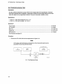
3·9. Dynamic Range Test
Description:
This test verifies the dynamic range of each pod by ensuring that:probe assemblies do not saturate. A
square wave with dc levels set at specified limits is applied. A visual account of one positive pulse per
division at a duty cycle of approximately 50 ns ± 4 ns indicates a passed test.
Specification:
Dynamic Range: ± 7 Volts.
Equipment:
Function Generator ............................................................................................................................. HP 8116A
BNC Cable ........................................................................................................................................... HP 10503A
50 Ohm Feedthru ................................................................................................................................ HP 10100C
Test Connector see figure 3-1
Procedure:
1. Connect the HP 16515A!16A and test equipment as in figure 3-18.
Note
In ·this setup, eight channels are connected at a time. All ground leads must be
grounded to ensure accurate test results.
HP 16515A/16A
TIMING
ANALYZER
FUNCTION
GENERATOR
-D-
SEE
FIG 3-1
8
8
-....
GNO
DATA
500
FEEOTHROUGH
TEST
CONNECTOR
3-18. Test Equipment Setup
3-12
16~1~/BLe8
HP 16515N16A - Performance Tests
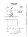
2. Set function generator output for a 10 MHz square wave as shown in figure 3-19.
-..j
7V------------ I
3V------------
50NS
f.-
~
L-J
I
I--t- 100NS-.j
ov-----------------------------115~1~lWfel
3-19. Square Wave Pulse
Setting for HP 8116A:
Parameter
Setting
Mode
NORM
Waveform
Square Wave
Frequency
10 MHz
Duty Cycle
50%
High Level (HIL)
+ 7 Volts
Low Level (LOL)
+ 3 Volts
Output Mode
ENABLE
3. Turn instrument power on.
4. From the startup screen shown in figure 3-5 in previous test, touch the following fields in the ordered sequence below:
a. System
b. 1 GHz Timing (If multiple timing modules, pick the one to test)
3-13
HP 16515A/16A - Performance Tests
5. In the Format screen. touch pod threshold field for pod under test. See figure 3-20.
1 GHz Timing E) (
~
F'ormet
(
Run
3-20. Pod Threshold Field
6. Touch User Defined and set threshold. using pop-up keypad. to
+ 5 Volts. then touch DONE.
7. From the Format screen. touch Format. then touch Trace.
8. Set Trace screen as shown in figure 3-21.
(
1 GHz Timing E) (
~
Troce
Lobe I >
( MASTER) ( EXPNDR )
Bose>
~~
F'1 nd
r
Pottern
Equol
~~
present for
Then find
Edge
0
(
:5 ns )
c:::Jc:::J
3-21. Trace Screen
9. From the Trace screen touch Trace. then touch Waveforms.
3-14
(
Run
HP 16515N16A - Performance Tests
10. In the Waveforms screen set the s/Div to 100 ns.
11. Touch Run then drag finger to Single. See figure 3-22.
3-22. Run-Single Field
12. The resulting waveforms should look like figure 3-23. Adjust the delay to line up pulse edge with center screen graticule. There should be 1 pulse per division at a duty cycle of approximately 50 %.
(
I GHz Tlm1 ng E) (
( Accumulate
Off
(
1
f Delay
1
-28 ns
s/Dlv )
100 ns
r-r-IMASTER C
MASTER I
MASTER 2
MASTER "
MASTER . :
MASTER !5
MASTER 6
MASTER 7
'MASTER 8 ' MASTER S
MASTERIC
MASTER 11
MASTER 12
MASTER 1
MASTER I..:
MASTER 1
~ (
Haver orms )
1 ns
IsamPle period·
Marlcers
Off
r--
1
r--
r--
r--
: r--
Run
I
r--
r--
r--
:
:
:
-
'--
10-
!...f-
lo-
'-
'-
10-
:
:
:
:
3-23. Waveform Data
Note
Nonsaturated input channels will display a positive pulse width of 50 ns ± 4 ns.
3-15
HP 16515N16A - P~rformance Tests
13. Adjust function generator LOL to -7 volts and the HIL to 0 volts.
14. Touch Waveforms, then touch Format.
15. In the Format screen, touch the pod threshold field for pod under ~est and select User Defined. Set
threshold for· 3.5 Volts.
16. Touch Format, then touch Waveforms.
17. In the waveforms screen touch Run.
18. The resulting waveform should look like the previous figure 3-23.
19. Disconnect master pod 1 probes and connect master pod 2 probes to the test connector.
20. Touch Waveforms, then touch Format. Reset function generator as in step 2 and repeat steps 5
through 18.
21. If there is an HP 16516A Expansion Card in the module, continue with steps 22 through 24.
22. In the Waveforms screen, touch the Label field as shown in figure 3-24.
(
1 GHz Timl ng E) (
Accumulete)
J
10..-
-
1 ns
IsemPle per10d •
orr
s/D1y
100 ns
~
Heyer orms
Deley
-26 ns
r-
i.-
J
Merlcer s
-
-
Off
Run
I
J
r-
'--
(
r-
-
-
r-
....
-
-
r-
"'"--
-
-
"'"--
3-24. Label Field
23. In the Waveforms Selection screen, touch the following fields in the ordered sequence below:
a. Action Insert (toggles to Replace)
b. Expndr (or B if label field is left at default)
c. Done
24. Touch Waveforms, then touch Format. Reset function generator as in step 2 and repeat steps 5
through 20 for expansion pod 1 and expansion pod 2.
3-16
HP 16515A/16A - Performance Tests
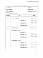
Table 3-1. Performance Test Record
Hewlett-Packard
Tested By
Model 16515A/16A
Work Order No.
1 GHz Timing Analyzer
Date Tested
Board No.
Paragraph
3-7
Test
Results
Minimum Swing Voltage
Passed
Failed
Passed
Failed
Master Pod 1 (0-7)
Master Pod 2 (8-15)
Expndr Pod 1 (0-7)
Expndr Pod 2 (8-15)
3-8
Threshold Accuracy
Threshold setting: + 5 Volts
Master Pod 1 (0-7)
Master Pod 2 (8-15)
Expndr Pod 1 (0-7)
Expndr Pod 2 (8-15)
Threshold setting: - 3.5 Volts
Master Pod 1 (0-7)
Master Pod 2 (8-15)
Expndr Pod 1 (0-7)
Expndr Pod 2 (8-15)
3-17
HP 16515A/16A - Performance Tests
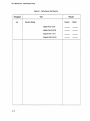
Table 3-1. Performance Test Record
3-9
Results
Test
Paragraph
Dynamic Range
Passed
Master Pod 1 (0-7)
Master Pod 2 (8-15)
Expndr Pod 1 (0-7)
Expndr Pod 2 (8-15)
3-18
Failed
HP 16515A/16A - Adjustments
SECTION IV
ADJUSTMENTS
4-1. ADJUSTMENT AND CALIBRATION
This section normally provides information ,on
when to calibrate, how to calibrate, and how to adjust the module. The HP 16515A/16A Timing
Analyzer Module has no adjustments and requires
no calibration.
4-1
TABLE OF CONTENTS
REPLACEABLE PARTS
5-1.
5-2.
5-3.
5-4.
5-5.
5-6.
Introd uction ...........................................................................................................................5-1
Abbreviations ........................................................................................................................5-1
Replaceable Parts List ...........................................................................................................5-1
Ordering Information ............................................................................................................5-1
Exchange Assemblies ..........................................................................................................5-1
Direct Mail order System ......................................................................................................5-2
HP 16515A/16A - Replaceable Parts
SECTION V
REPLACEABLE PARTS
5-1. INTRODUCTION
• Description of part.
This section contains parts and ordering information for the HP 16515A/16A 1 GHz Timing Analyzer
Module. Table 5-1 lists the reference designators
and abbreviations used throughout this manual.
Table 5-2 lists all replaceable parts by reference
designator.
• Check digit.
5-2. ABBREVIATIONS
Table 5-1 lists abbreviations used throughout the.
manual. In some cases two forms of the abbreviations are used, one in all capital letters, the other
partially or not capitalized. This was done because
the abbreviations in the parts list are always all
capitals. However, in other parts of the manual
other abbreviation forms are used with both lower
and uppercase letters.
5-3. REPLACEABLE PARTS .LIST
Table 5-2 lists replaceable parts and is organized
as follows:
• Electrical assemblies in alphanumerical order
by reference designation.
• Chassis-mounted parts in alphanumerical
order by reference designation.
• Electrical assemblies and their components in
alphanumerical order by reference designation.
The information given for each part consists of the
following:
The total quantity for each part is only given once
at the first appearance of the part number in the list.
5-4. ORDERING INFORMATION
To order a part listed in the replaceable parts table,
quote the Hewlett-Packard part number, check
digit, indicate the quantity required, and address
the order to the nearest Hewlett-Packard office.
To order a part that is not listed in the replaceable
parts table, include the instrument model number,
instrument serial number, the description and function of the part, and number of parts required. Address the order to the nearest Hewlett-Packard office.
5-5. EXCHANGE ASSEMBLIES
Exchange assemblies are available when a
repairable assembly is returned to Hewlett-Packard. These assemblies have been set up on an Exchange program. This allows the customer to exchange the faulty assembly with one that has been
repaired, calibrated, and performance verified by
the factory. The cost is significantly less than that
of a new assembly.
Exchange assemblies are listed in a separate section in the replaceable parts table. They have a
part number in the form XXXXX-695XX (where the
new parts would be XXXXX-665XX). Before ordering an exchange assembly, check with your local
parts or repair organization for procedures.
• Complete reference designation.
• Hewlett-Packard part number.
• Total quantity (Qty) per instrument.
5-1
HP 16515A/16A - Replaceable Parts
5-6. DIRECT MAIL ORDER SYSTEM
Within the USA, Hewlett Packard can supply parts
through direct mail order. The advantages are as
follows:
• Direct ordering and shipment from HewlettPackard Parts Center in Mountain View,
California.
• No maximum or minimum on any mail order
(there Is a minimum order for parts ordered
through local Hewlett-Packard offices when
orders require billing and invoicing).
5-2
• Prepaid transportation (there is a small handling charge for each order).
• No invoices - to provide these advantages,
check or money order must accompany each
order. Mail order forms and specific ordering
information are available through your local
Hewlett-Packard offices.
HP 16515N16A - Replaceable Parts
Table 5-1. Reference' Designator and Abbreviations
REFERENCE DESIGNATOR
A
B
8T
C
CR
DL.
DS
E
-assembly
-fan;motor
-battery
-capacitor
- diode;dlode thyristor;
varactor
-delay line
- annunciator;lamp;L.ED
- misc. electrical part
F
FL
H
J
L.
MP
P
-fuse
-filter
-hardware
- electrical connector
(stationary portion);jack
-coil;lnductor
-mise. mechanical part
- electrical connector
(moveable portlon);plug
Q
R
RT
S
T
TB
TP
-lransistor;SCR;
trlode thyristor
-resistor
- thermistor
- switch;jumper
- transformer
-Iermlnal board
-lest point
U
V
VR
W
X
Y
-Integrated circuit;
microcircuit
- electron tube; glow
lamp
-voltage regulator;
breakdown diode
-cable
-socket
- crystal unlt(piezoelectric or quartz)
ABBREVIATIONS
-amperes
- analog-to-digital
AC
- alternating current
ADJ
- adjust(ment)
AL.
-aluminum
-amplifier
AMPL
-analog
ANLG
ANSI
- American National
Standards Institute
-assembly
ASSY
ASTIG
- astigmatism
ASYNCHRO - asynchronous
AnEN
- attenuator
AWG
- American wire gauge
-balance
BAL
BCD
- binary-code decimal
-board
BD
BFR
-buffer
-binary
BIN
BRDG
-bridge
-bushing
BSHG
-bandwidth
BW
C
- ceramlc;cermet
(reSistor)
.. calibrate;calibration
CAL.
.. carbon composition
CC
.. counterclockwise
CCW
-ceramic
CER
.. cubic feeVminute
CFM
-choke
CH
.. chamfered
CHAM
-channel
CHAN
-character
CHAR
-centimeter
CM
CMOS
- complementary metaloxide-semiconductor
CMR
- common mode rejection
CNDeT
-conductor
-counter
CNTA
-connector
CON
CONT
-contact
CRT
. - calhode-ray tube
-clockwise
CW
a diameter
D
.. digital-te-analog
D/A
DAC
- digital-te-analog
converter
DARL
- darlington
-data
DAT
-double
DBL
DBM
- decibel referenced
t01mW
DC
- direct current
DCDR
-decoder
-degree
DEG
DEMUX
- demultiplexer
-detector
DET
DIA
-diameter
,. dual in-line package
DIP
-division
DIV
DMA
- direct memory aeeess
DPDT
- double-pole,
double-throw
DRC
'" DAC refresh controller
-driver
DRVR
A
NO
DWL
ECL.
ELAS
EXT
F
FC
FD
FEM
FF
FL.
FM
FR
FT
FW
FXD
GEN
GND
GP
GRAT
GRV
H
HD
HDND
HG
HGT
HL.CL
HORIZ
HP
HP-IB
HR
HV
HZ
VO
IC
ID
IN
INCL
INCAND
INP
INTEN
INn.
INV
JFET
JKT
K
L.
L8
L.CH
LCL
L.ED
LG
U
LK
LKWR
LS
LV
M
MACH
MAX
-dowel
- emitter coupled logic
-elastomeric
-external
.. farads;metal film
(resistOr)
- carbon film!
composition
-feed
-female
-flip-flop
-flat
-foam;from
-front
-gain bandwidth
product
-full wave
-fixed
-generator
-ground(ed)
- general purpose
-graticule
-groove
.. henrles;hlgh
-hardware
-hardened
-mercury
-height
-helical
-horizontal
- Hewlett-Packard
- Hewlett-Packard
Interface Bus
-hourIs)
- high voltage
-Hertz
- inpuVoutput
-Integrated circuit
- inside diameter
-inch
- include(s)
- incandescent
-input
-Intensity
-internal
-inverter
- junction fieldeffect transistor
-jacket
"kilo(103)
-low
.. pound
-latch
-local
-light-emittlng
diode
=-Iong
-lithium
-lock
-Iockwasher
-low power Schottky
-low voltage
- mega(1 06);megohms;
meter(distance)
-machine
-maximum
MFR
MICPROC
MINTA
MISC
MLD
MM
MO
MTG
Mn.C
MUX
MW
N
NC
NMOS
NPN
NPRN
NRFR
NSR
NUM
OBD
ocn.
OD
OPAMP
OSC
P
PIO
PC
PCB
PD
PF
PI
PL.
PLA
PLST
PNP
POLYE
POS
POT
POZI
PP
PPM
PRCN
PREAMP
PRGMBL
PRL
PROG
PSTN
PT
PW
PWR
R-S
RAM
RECT
RET
RF
RGLTR
RGTR
RK
RMS
- manufacturer
- microprocessor
-miniature
- miscellaneous
-molded
-millimeter
.. metal oxide
-mounting
-metallic
- multiplexer
-milliwatt
-nano(1Q-e)
- no connection
- n-channel metaloxide-semlconductor
- negative-positivenegative
-neoprene
- not recommended for
field replacement
- not separately
replaceable
-numeric
- order by description
-octal
-outside diameter
- operational amplifier
-oscillator
.. plastic
-part of
- printed circuit
.. printed circuit board
.. power dissipation
- picofarads
-plug in
"'plate(d)
.. programmable logic
array
-plastic
- positive-negativepositive
-polyester
- positlve;positlon
- potentiometer
-pozidrlve
- peak-te-peak
- parts per million
-precision
- preamplifier
- programmable
"'parallel
- programmable
-position
-point
- potted wir8lNOund
-power
-reset-set
- random-access
memory
- rectifier
-retainer
- radio frequency
-regulator
-register
-rack
.. root-mean-square
RND
ROM
RPG
AX
S
SCR
SEC
SEG
SEL
SGL
SHF
Sf
SIP
SKT
SL.
SLDR
SLT
SOLD
SPCL
sa
SREG
SRQ
STAT
STD
SYNCHRO
TA
TBAX
TC
TO
THD
THK
THRU
TP
TPG
TPL.
TRANS
TRIG
TRMR
TRN
Tn.
TX
U
UL
UNREG
VA
VAC
VAR
vee
vee
VERT
VF
VS
W
WI
WIO
WW
XSTR
ZNR
oC
of
oK
-Round
- read-only memory
- rotary pulse generator
-receiver
- Schottky-clamped;
seconds(time)
- screw,sillcon
controlled rectifier
- second (time);seeon
dary
-segment
-selector
-single
-shift
-silicon
-single in-line
package
-skirt
-slide
-solder
-slot(ted)
-solenoid
-special
-square
-shift register
- service request
-static
-standard
-synchronous
-tantalum
-tubeaxial
- temperature coefficient
.. time delay
-thread(ed)
-thick
-through
-test point
-tapping
-triple
- transformer
- trigger(ed)
-trimmmer
-tum(s)
- transistor-transistor
-transmitter
.. micro(1 Q-6)
.. Underwriters
Laboratory
- unregulated
-voltampere
-volt,ac
-varlable
- voltage-controlled
oscillator
-volt,dc
-vertical
- voltage,filtered
-versus
-watts
-with
-without
- wir8lNOund
'" transistor
-zener
- degree Celsius
(Centigrade)
- degree Fahrenheit
.. degree Kelvin
5-3
HP 165 15A/16A - Replaceable Parts
W1
H3 & H6", A
1.fl2 & MPl1
l'
a.
H2
MPB
& HS
& MP17
H7
M?14
5-1. Pa rtS I''dentification
5-4
1!!515/[X31
HP 16515A/16A - Replaceable Parts
Table 5-2. Replaceable Parts List
Reference
Designator
HP Part
Number
C Qty
16515-13510
16515-69501
16516-69501
4
1
2
Description
0
1
1
1
Mfr
Code
Mfr Part
Number
HP 16515N16A Oper System Disc
HP 16515A Exchange Pssy.
HP 16516A Exchange Assy.
HP 16515A
E1
H1
16515-66501
16515-61604
5959-0288
16515-69502
16500-2240 1
5
9
4
2
5
1
16
2
2
2
Board Assembly
Probe Assembly
Grabber Assembly Set Oty 20
Probe Lead Set Kit
Endplate Thumbscrew
H2
H3
MP1
MP2
MP3
0515-0430
0515-0665
16515-40503
16515-01201
0510-0684
3
6
3
6
9
3
4
1
1
2
M3 X 6 PH T10 Endplate Screw
M3 X 14 PH T10 Retainer Screw
Card Endplate
Probe Assembly Retainer
Thumbscrew Retaining Ring
MP4
MP5
MP6
MP7
MP8
MP9
16500-29101
16515-94302
16515-43102
16500-94303
5959-0291
16515-94303
6
3
4
7
9
4
1
1
2
1
1
1
Ground Spring
Timing Master Label
Probe ID Clip
Probe 10 Clip Label Set
Serial Tag
Probe Assembly Label Set
A1
A2.
f.:3
HP 16516A
H4
16516-6650 1
16515-61604
5959-0288
16515-69502
16500-22401
6
9
4
2
5
1
16
2
2
2
BoardAssembly
Probe Assembly
Grabber Assembly Set Oty 20
Probe Lead Set Kit
Endplate Thumbscrew
H5
H6
H7
MP10
MP11
0515-0430
0515-0665
0515-1246
16515-40503
16515-01201
3
6
1
3
6
3
4
6
1
1
M3 X 6 PH T10 Endplate Screw
M3 X 14 PH T10 Retainer Screw
M3 X 0.5 Mach. Card Screw
Card Endplate
Probe Assembly Retainer
MP12
MP13
MP14
MP15
MP16
0510-0684
16500-29101
16516-94301
16515-43102
16500-94303
9
6
4
4
7
2
1
1
2
1
Thumbscrew Retaining Ring
Ground Spring
Timing Expansion Label
Probe 10 Clip
Probe ID Clip Label Set
MP17
MP18
W1
5959-0291
16515-94303
16516-61601
9
4
7
1
1
1
Serial Tag
Probe Assembly Label Set
Ribbon Cable Pssembly
A4
AS
A6
E2
5-5
TABLE OF CONTENTS
SERVICE
6-1.
6-2.
6-3.
6-4.
6-5.
6-6.
6-7.
6-8.
6-9.
Introduction .......................................................................................................................... 6-1
Safety Requirements............................................................................................................. 6-1
Recommended Test Equipment .......................................................................................... 6-1
Module Block Diagram and Theory Of Operation ............................................................... 6-1
Self Tests .............................................................................................................................. 6-4
Troubleshooting ................................................................................................................... 6-9
Module Replacement ........................................................................................................... 6-28
Probe Assembly Replacement ............................................................................................. 6-31
Extender Board Installation ................................................................................................. 6-35
HP 16515A/16A - Service
SECTION VI
SERVICE
6-4. MODULE BLOCK DIAGRAM AND
THEORY OF OPERATION
6-1. INTRODUCTION
This section contains Information for servicing the
HP 16515A/16A 1 GHz Timing Analyzer Module.lncluded is a block level theory and procedures for
module level self diagnostics and troubleshooting.
If the module or a probe assembly is determined
faulty, procedures are provided for module and
probe assembly replacement.
6-2. SAFETY REQUIREMENTS
Specific warnings, cautions, and instructions are
placed wherever applicable throughout the
manual. These must be observed during all phases
of operation, service, and repair of the module.
Failure to comply with them violates safety standards of design, manufacture, and intended use of
this module. Hewlett-Packard assumes no liability
for the failure of the customer to comply with these
safety requirements.
The following paragraphs contain block level
theory of operation. This theory is not intended for
component level troubleshooting, rather it is to be
used to help isolate a module failure to card level.
For component level troubleshooting, the HP
16515A/16A Service Data Supplement is required.
This supplement contains schematics, component
level theory .of operation, component locaters and
a parts Iistforthe HP 16515A/16A 1 GHz Timing
Analyzer Module.
The HP 16515A 1 GHz Timing Analyzer Master
Card is a one board, 16 channel timing analyzer. It
can sample data at up to a 1 GHz rate and be expanded by 16 channels to a total of 32 channels
when a HP 16516A 1 GHz Timing Expansion Card
is added. See figure 6-1.
6-3. RECOMMENDED TEST
EQUIPMENT
Table 1-2 lists recommended test equipment. Any
equipment that satisfies the critical specification
given in the table may be substituted for the recommended models.
BACKPLANE CONNECTOR
HP 16515A
1 GHZ TIMING
MASTER
INTERCARD CONNECT
HP 16516A
EXPANSION
11l515/BLIl-4
Figure 6-1. Module Block Diagram
6-1
HP 16515A/16A - Service
HP 16515A Master Card
TIMEBASE, TRIGGER AND MEMORY
INTERFACE AND 1MB
The timebase is comprised of three major interactive components. Collectively they generate
sample clocks and control prestore and poststore
delays.
The microprocessor interface circuits include the
system data transceiver, decoders for module controllines, a card 10 latch, and intermodule bus
(1MB) circuits. The 1MB enables the timing analyzer
module to trigger/arm other modules or be triggered/armed by the state of another module in the
mainframe.
PROBES
The probes are a passive design. Each of the two
probe pods contains 8 data input lines with grounding at the probe tips.
POD LOADING AND COMPARATORS
Input data from the probe pods are loaded by an
RC network and compared to a pod threshold. The
comparators then translate the Input signals to
ECLlevels.
8 CHANNELS
PER POD
r
INPUT DATA
)
v
The two 8 channel acquisition circuits are identical
except for the operation of the trigger circuitry.
One acquisition chip is the designated control
chip. While pattern and edge detection is performed on unsampled data for each 8 channel
data slice, the results are combined in the control
chip. The control chip then performs duration
count and final trigger detection for the module.
Data is sampled on both edges of the sample
clock. The maximum sample clock rate of 500
MHz will in effect sample at 1 GHz. After sampling,
the data is slowed down by a factor of four and is
stored in memory.
..
...
DATA
PODS
DATA
1-2
)
COMPARATORS
v
0/" CONVERTOR
/~
CPU. ADDRESS
DATA
A
A
BUS
v
"
A
1MB BUS
'I
)
")
-v
BUS
INTERFACE
1MB
K
ANAL YZER BUS
"
DATA
"
-v/
TIMEBASE
INTERCARD
CONNECT
MEMORY
TRICGER
i}
I
1MB CONTROl.
lt5lSlIl...
Figure 6-2. HP 16515A 1 GHz Timing Master Block Diagram
6-2
.HP 16515A/16A - Service
HP 16516A Expansion Card
TRIGGER AND MEMORY
INTERFACE
The two 8 channel acquisition circuits are Identical.
Pattern and edge detection are performed on unsampled data for each 8 channel data slice and the
results are transmitted to the control chip on the
master card.
The microprocessor interface circuits are minimal.
They include a system data transceiver and a card
10 latch. The clock and control lines are brought
onto the expansion card through the intercard connect cable or decoded from the system backplane.
PROBES
The probes are identical to the master card probing scheme. Each probe pod contains 8 data input
lines with grounding at the probe tip.
Data is sampled on both edges of the sample
clock. The maximum sample clock rate of 500
MHz will in effect sample at 1 GHz. After sampling.
the data is slowed down by a factor of four and is
stored in memory.
POD LOADING AND COMPARATORS
Input data from the probe pods are loaded by an
RC network and compared to a pod threshold. The
comparators then translate the input signals to
ECLlevels.
8 CHANNELS
PER POD
"
INPUT DATA)
v
I
DATA
PODS
1-2
DATA
")
"-
COMPARATORS
v
D/A
BUS
.....
~
/
BUS
INTERFACE
~
"
MEMORY
CONVERTOR
TRIGGER
/">.
il
CPU ,ADDRESS
DATA
/I
DATA)
ANALYZER BUS
INTERCARD
. CONNECT
'&~'~/BLt~
Figure 6-3. HP 16516A 1 GHz Timing Expansion Block Diagram
6-3
HP 16515A/16A - Service
6-5. SELF TESTS
Self tests for the HP 16515A/16A 1 GHz Timing Analyzer Module will identify the improper operation of
major functional areas in the module. They are not intended for component level diagnostics. If there are
multiple timing modules, each must be selected for testing at the main Test System menu.
All self tests can be run without access to the interior of the instrument. If a failure is found, the
troubleshooting flowchart in paragraph 6-6 will instruct you to change one ·or both cards in the module, a
probe assembly, or the intercard cable.
The following procedure outlines how to access, run, and exit the self tests utilities. One test is used as an
example in the procedure. Individual test definitions appear at the end of the test procedure.
The effects of ELECTROSTATIC DISCHARGE can damage electronic components. Use grounded wriststraps and mats when performing any kind of service to this instrument or the cards in it.
Self Test Access Procedure:
1. Disconnect all inputs and turn power switch on.
2. From the startup screen shown in figure 6-4, touch Configuration field, then touch Test.
",-_s...y_st_em_ _J
(conf IguretiOnJ
Cords
A
B
HP-IB
~
C
Controller
1 GHz TIMING
EXPANDER
RS-232C
1 GHz TIMING
MASTER
~
Printer
Figure 6-4. Startup Screen
6-4
HP 16515N16A - Service
3. Touch box to load Test System. See figure 6-5.
~__
sy~s_te_m__~) (~___
T_es_t__~
;<~{\~~ ,;;\~';.f .J,"'" .~~:) ~;.t·~~..t \>~~ ~: <~
•
.'to Loud Tes t Sys tem
:~~ \r~~:~;::t$l~;~~~" • ~~;
Cord ID codes
I
SLOT A SLOT B SLOT C SLOT 0 SLOT E
none
none
none
002
001
Figure 6-5. Load Test System
4. From test screen in figure 6-6, touch Test System, then touch 1 GHz Timing. (If multiple 1 GHz
Timing modules, select the one to be tested)
Test System
(conr 19urOtiOn)
Cords
A
B
C
1 GHz TIMING
EXPANDER
1 GHz TIMING
MASTER
RS-232C
~
Printer
Figure 6-6. Test System Screen
6-5
HP 16515N16A - Service
5. Figure 6-7 is the main self test menu. Self tests can be run individually by touching a specific test
field, or altogether by touching IIAlI16515/16 Testsll. When IIAII16515/16 Testsll is run, the test status
will change to "TESTEDII. When individual tests are run, the status will change to either IIPASSED or
FAILEDII.
1 GHz Timing E)
Fenout Test
stetus
UNTESTED
Intermodule Bus
s te tus
UNTESTED
Memory Test
stetus
UNTESTED
Pettern end Edge
stetus
UNTESTED
Pettern Tr1gger
stetus
UNTESTED
Pettern Edge Duretton
stetus
UNTESTED
Edge Trtgger
stetus
UNTESTED
Timebese/CloCK Test
UNTESTED
s te tus
Duretion Trigger
stetus
UNTESTED
All 16515/16 Tests
s t e t us
UNTESTED
Figure 6-7. Main Test Menu
6. Touch Fanout Test
7. An individual test run screen, see figure 6-8, will give the test name, a brief description of the test,
number of test runs, and test failures for each slot/pod .
1 GHz Timing E )
(
Fenout Test
16516
.. Dl
16515
.. D2
.. EI
.. E2
Timebese
Pheser
runs
Run
fe1lures
o
o
o
o
o
o
o
o
o
o
o
o
This test exercises the dete peth et Ins,
Bns, 160ns, & 3.2 us semple periOdS.
Disconnect probes before running test
Done
Figure 6-8. Fanout Test Run Screen
8. Touch Run, then drag finger to Single or Repetitive.
9. During the time a Single run or a Repetitive run is executing, the Run field will change to Stop.
6-6
HP 16515A/16A - Service
10. To stop a Repetitive run, touch Stop. See figure 6-9. To exit the test touch Done.
1 GHz Timing E)
Fonout Test
..
16516
..
16515
..
..
01
02
El
E2
Timebese
Pheser
runs
25
25
25
25
25
25
feilures
0
0
0
0
0
0
This test e~ercises the dete peth et Ins,
8ns, 160ns, & 3.2 us semple periods.
Disconnect probes before running test
Done
Figure 6-9. Stop Field
11. Select the next test from the main test menu.
12. Repeat steps 8 through 11 until all tests are run.
13. To exit the self tests, touch the following fields In the numbered sequence below:
1. 1 GHz Timing
2. Test System
3. Configuration
4. Exit Test
14. Touch the box to Exit Test System. See figure 6-10.
Test System
) (
Cord 10 codes'
E~it Test
SLOT A SLOT B SLOT C SLOT D SLOT E
none
none
none
002
001
Figure 6-10. Exit Test System
6-7
HP 16515N16A - Service
Test Descriptions:
Some individual self test screens show run/failure information for the mainframe slot followed by the pod
number. An example of this is, mainframe slot D and pod 1 will show up on test screen as D 1. Self test
failures for circuits or components common to all probe pods will be registered under their own description as well as a slot/pod failure.
Fanout Test:
This is a functional test of the acquisition chips, memory chips, comparators and timebase system. At
sample periods of 1 G, 125 M, 6.25 M, and 312.5 k samples/sec, the threshold is set to minimum and a full
memory is acquired and read back. Then the threshold is set to maximum and the procedure is repeated.
Memory chip failures are shown by physical location with the lower case letters a through d. Test information on memory chip location, timebase, and phaser is used by the HP service center for more detailed
failure analysis.
Memory Test:
This test checks the memory chips ( eight on 16515A and eight on 16516A) by clocking a checkerboard
pattern into memory at a 1GHz rate. The CPU then reads the memory to verify the appropriate pattern
stored. Memory chip failures are shown by physical location with the lower case letters a through d. Test
information on memory chip location and the phase generator is used by the HP service center for more
detailed failure analysis.
Pattern Trigger Test:
This test checks the pattern trigger capabilities and consists of three parts.
1. Each data channel in succession is programmed to detect a "1" while the other channels are "don't
care".
2. Each data channel in succession is programmed to detect a "0" while the other channels are "don't
care".
3. Data channel 0 of pod 1 is programmed to detect a "not equal 1" while the other channels are "don't
care".
Failing channels are designated by a "#" (pound) while those passing will be indicated by a "." (dot).
Status bit information and the trigger numbers next to the 16515 label are is used by the HP service center
for more detailed failure analysis.
Edge Trigger Test:
This test checks the edge trigger capabilities and consists of two parts.
1. Each data channel in succession is programmed to detect a rising edge, while the other channels
are "'don't care".
2. Each data channel in succession is programmed to detect a falling edge, while the other channels
are "don't carel!.
Failing channels are designated by a "#" (pound) while those passing will be indicated by a "." (dot).
Status bit information and the trigger numbers next to the 16515 label are used by the HP service center
for more detailed failure analysis.
6-8
HP 16515A/16A - Service
Duration Trigger Test:
This test checks the greater than and less than pattern duration circuitry and consists of two parts.
1. Data channel 0 of pod 1 Is programmed to detect a "1" pattern of greater than 20 J.1.s duration.
2. Data channel 0 of pod 1 is programmed to detect a "1" pattern of less than 20 J.1.s duration
Pvd (prestore valid) bit and Imc Oow measurement complete) bit information is used by the HP service
center for more detailed failure analysis.
Intermodule Bus Test:
This test exercises the intermodule bus interface. The timing analyzer is programmed to trigger on "don't
care", armed by the 1MB. The 1MB is then triggered by the CPU. Pvd (prestore valid) bit and Imc Oow
measurement complete) bit information is used by the HP service center for more detailed failure analysis.
Pattern And Edge Test:
This test ensures that the pattern and edge detectors interact properly. Data channel 0 on pod 2 is
programmed to detect a "1" pattern. Data channel 0 on pod 1 is programmed to detect a rising edge. The
sample rate is set to 1 Gsamples/sec and duration is set to minimum. A trigger should occur on the
second rising edge of channel 0 on pod 1. Lmc Oow measurement complete) bit information is used by
the HP service center for more detailed failure analysis.
Pattern Edge Duration Test:
This test ensures the pattern, edge, and duration interact properly. The triggers are programmed the same ~
as in the pattern and edge test, with the greater than duration set to 20 J.1.s and a sample rate of 80 ns. Pvd
(prestore valid) bit and Imc Oow measurement complete) bit information is used by the HP service center
for more detailed failure analysis.
Timebase/Clock Test:
This test exercises the operation of the oscillator, timebase, and sync/mux chips. The test consists of two
parts.
1. At a clock rate of 625 Hz, the high time and low time of the sample clock is recorded and the delta is
compared to nominal.
2. The prestore counter is loaded with 30000 and the sample clock is set for 16 ns period. The time
until the pvd (prestore valid) bit comes true is measured and compared to nominal.
All 16515/16 Tests:
When this test is selected, all tests are run automatically one time.
6-6. TROUBLESHOOTING
If self tests indicate a fail ure, begin at the START of the troubleshooting flow chart shown in figure 6-11. If
you are troubleshooting a one card module (HP 16515A master), start on troubleshooting sheet 1. If you
are troubleshooring a two card module (HP 16515A and HP 16516A), start on troubleshooting sheet 2.The
flowchart will instruct you to replace a faulty card, probe assembly or cable, or refer you to other flow
charts for a further isolation process.
6-9
HP 16515N16A - Service
HP 16515A STANDALONE MAIN TROUBLESHOOTING FLOWCHART
>.H:·
:p"
Troubleshooting Sheet 1
':1<
(~i
.:1:'.
>5):
RUN MAINFRAME
SELF TESTS
:'O:s\
···'. T/·
"A:
··,N.<
NO
0.':
A
. . L>
REPAIR MAINFRAME.
REFER TO HP 16500A
MAINFRAME SERVICE BOOK
:0.·•
. ·.·.N .
>E}
YES
··,·rvf:.
.A.
. ' 1:(
RUN MODULE
SELF TESTS WITH
STANDALONE HP 16515A
N
T{
YES
R··
REPLACE
HP 16515A MASTER
0··
If
e>
VERIFY GOOD
PROBE ASSEMBLIES
REFER TO
"TESTING PROBE ASSEMBLIES"
TROUBLESHOOTING SHEET 18
.C·
.• ·e:::
>s\
fr:
0':
0'
REPLACE FAULTY
PROBE ASSEMBLIES.
~N=O~ REFER TO PARAGRAPH 6-8
"PROBE ASSEMBLY
REPLACEMENT"
"'T:
]
... :.
N'::
"G':
YES
:-":-:-:':-:.,;
/Ft
YES
bY
NO
0.:
"w·:
CONTACT HP
SERVICE CENTER
c:
.~••.•
'Ft
Figure 6-11. Troubleshooting Flowchart
.T
6-10
T1651501
HP 16515N16A - Service
HP 16515A/16516A MAIN TROUBLESHOOTING FLOWCHART
.:- ... ;.;. ........ .
Troubleshooting Sheet 2
'f-i>'
::::¥1::i
'6:'"
:::5:>
A ~----------~~
FROM
TROUBLESHOOTING
SHEETS 3-5.8.9,
12.13.16,17
>:;1:
RUN MAINFRAME
SELF TESTS
i~'
::>1:.:
NO
\s:<
»5.
\:1'<
6/
REPAIR MAINFRAME.
REFER TO HP 16500A
MAINFRAME SERVICE BOOK
>·M::
iA.
:/.1:>
YES
·:N
RUN MODULE
SELF TESTS
WITH
HP 16515A AND HP 16516A
·r:·
••.••
YES
~ .....
:U'
::B
VERIFY GOOD
PROBE ASSEMBLIES
REFER TO
"TESTING PROBE ASSEMBLIES"
ON TROUBLESHOOTING
SHEET 18
THEN RETURN HERE
:"'C>'
:E:
>:S:
. . I-I
:0::
REMOVE HP 16516A FROM
INSTRUMENT AND
CONFIGURE MODULE AS
HP 16515A STANDALONE
::::0:
::T· .
tl::
:"N>
CONTACT HP
SERVICE CENTER
"GO
RUN
MODULE
SELF TESTS WITH
STANDALONE HP 16515A
REPLACE
FAULTY PROBE ASSEMBLIES.
REFER TO PARAGRAPH 6-8
"PROBE ASSEMBLY
REPLACEMENT"
:F. .
::>L
::0
'W:'
·C.
.:liO:
GO TO TROUBLESHOOTING
SHEET 3
(:A>
CONTACT HP
SERVICE CENTER
'. Fl
<:T'
T1551502
Figure 6-11. Troubleshooting Flowchart
6-11
HP 16515N16A - Service
HP 16515A/16516A MAIN TROUBLESHOOTING FLOWCHART
Troubleshooting Sheet 3
FROM TROUBLESHOOTING
SHEET 2
NO
REPLACE
HP 16515A MASTER
AND REATTACH
HP 16516A EXPANSION
REFER TO PARAGRAPH 6-7.
"MODULE REPLACEMENT"
RECONNECT
HP 16515A
AND
HP 16516A
CARDS
SEE NOTE 2.
TO CHECK CONNECTIONS
RUN
MODULE
SELF TESTS
INDIVIDUALL Y
GO TO TROUBLESHOOTING
SHEET 2
\:t~)<
"I"
::Ii}:
:}:I"'
:Nt
<:;.-:--
YES
:Sf-.::;
REPLACE
HP 16516A EXPANSION
:ooR:
>0>
·U<::
--.sy
RUN
EDGE TRIGGER
SELF TEST
L:
'E:
SEE NOTE 2.
TO CHECK CONNECTIONS
<:s:
.0:H::-
\0:
GO TO
"TESTING EDGE LINE"
ON TROUBLESHOOTING
SHEET 10
:0:-
--f:
GO TO TROUBLESHOOTING
SHEET 2
<In:
oN::>
-:-G:>
REPLACE
16516A EXPANSION
0-15
:::{1':
-0<-
Vi
c:
-:ft:
_>A
--f{-
GO TO TROUBLESHOOTING
SHEET 4
NOTE 1: EACH SELF TEST SCREEN SHOWS INDIVIDUAL
CARD AND POD FAILURES.
NOTE 2:
T:<
DOUBLECHECK THESE CONNECTIONS
1. INTERCARD CABLE
2. PROBE ASSEMBLIES
3. CARDS SEATED PROPERLY IN BACKPLANE
SEE NOTE 2.
TO CHECK CONNECTIONS
GO TO TROUBLESHOOTING
SHEET 2
Figure 6-11. Troubleshooting Flowchart
6-12
T1651503
HP 16515A/16516A MAIN TROUBLESHOOTING FLO'l:'::: ;,~.RT
Troubleshooting Sheet 4
FROM TROUBLESHOOTING
SHEET 3
RUN
PATTERN TRIGGER
SELF TEST
GO TO "TESTING PATTERN LINES"
ON TROUBLESHOOTING SHEET 6
;·M·
::·A::
.'j:<f::.
··.:N:
NO
REPLACE
16516A EXPANSION
>T·:
RUN
MEMORY
SELF TEST
/: R
SEE NOTE 3.
TO CHECK CONNECTI: :~S
:0 .
·u
·>8··
L
GO TO "TESTING CLOCKS"
TROUBLESHOOTING SHEET 14
GO TO
E:
.$
TROUBLESHOOT:~G
SHEET 2
>H
·:0··
:~
:/:1
:>·:N:·
:>G:
REPLACE
16516A EXPANSION
NOTE 3:
DOUBLE
1.
2.
3.
·.·>:F>:
SEE NOTE 3.
TO CHECK CONNECT!0~~S
TO TROUBLESHOOTING
SHEET 5
.:t.:.
::·:0··
CHECK THESE CONNECTIONS
INTERCARD CABLE
PROBE ASSEMBLIES
CARDS SEATED PROPERLY IN BACKPLANE
;;;~.
:::H::.
GO TO TROUBLESHOOTING
SHEET 2
<~
NOTE 4: ALL MEMORY IC LOCATIONS
a THROUGH d MUST PASS OR FAIL.
T>·
Figure 6-1J. Troubleshooting Flowchart
6-13
HP 16515N16A - Service
HP 16515A/16516A MAIN TROUBLESHOOTING FLOWCHART
Troubleshooting Sheet 5
E
FROM TROUBLESHOOTING
SHEET 4
GO TO "TESTING CLOCKS"
TROUBLESHOOTING SHEET 14
REPLACE
HP 16516A EXPANSION
:~:I;;
::I?\
:>N>::
SEE NOTE 6.
TO CHECK CONNECTIONS
<:T:::
R>:
:-0:>
:U.:(
/8/
GO TO TROUBLESHOOTING
SHEET 2
NOTE 5:
':L/:::::E::;:::
. s:;:
ALL MEMORY Ie LOCATIONS
o THROUGH d MUST PASS OR FAIL
NOTE 6:
DOUBLECHECK THESE CONNECTIONS
1. INTERCARD CABLE
2. PROBE ASSEMBLIES
3. CARDS SEATED PROPERLY IN BACKPLANE
H<
>'<0::
::':0,
:T::
>:r."!
>N/:
Figure 6-11. Troubleshooting Flowchart
"··G:."·
.F·.·
1(·
:0<'
'w,:
:>c:::
::~<;:
:R:<
,'.'J::
6-14
HP 16515N16A - Service
TESTING PATTERN LINES
Troubleshooting Sheet 6
NOTE 7:
REFER TO PARAGRAPH 6-9
"EXTENDER BOARD INSTALLATION"
THE HP 16515A MASTER MUST
BE INSTALLED BELOW EXTENDER BOARD
WITH THE INTERCARD CABLE DISCONNECTED.
FROM TROUBLESHOOTING
SHEET 4
TURN INSTRUMENT OFF
AND
PUT HP 16516A EXPANSION
ON EXTENDER BOARD
HP 16515A MASTER
CONNECT CHANNEL e POD 1
OF
HP 16516A EXPANSION TO
PULSE GENERATOR
HP 16515A116A
PULSE
GENERATOR
TIMING
ANALYZER
A
SEE FIGURE 3-1
IN SECTION 3
GND
POD 1 CHANNEL
(3
TEST
CONNECTOR
~
TO TROUBLESHOOTING SHEET 7
T165150S
Figure 6-11. Troubleshooting Flowchart
6-15
HP 16515A/16A - Service
TESTING PATTERN LINES
Troubleshooting Sheet 7
NOTE 8:
HP 16516A EXPANSION PODS
CAN INDICATE FALSE LEVELS
ON THE PROBE INPUTS, DUE TO
INTERCARD CABLE NOT BEING
CONNECTED. D!SREGARD THESE
FALSE READINGS.
FROM TROUBLESHOOTING
SHEET 6
TURN INSTRUMENT ON
AND
SETUP FORMAT
AND
TRACE SCREENS
SET PULSE GENERATOR AS FOLLOWS:
1. 50~ DUTY CYCLE
2. 2 MHZ FREOUENCY
3. +5V HIGH
4.
0V LOW
SET FORMAT
SCREE~
1 GHz Timi ng E) (
181
Pol
~
Forme t
Pod E2
(
~
TIL
Pod E1
)(
7 ...... 0
TIL
7 .•.... 0
Pod 02
)(
TIL
7 ...... 0
(
Run
Pod 01
)(
TIL
7 ...... 0
(Symbols)
::::: tB I~~~~~~~~ II ~~~~~~~~ IE:3 E:3
orr
SET TRACE
(
SCREE~
GHz Timing E) (
~
Trece
Lebe I )
( MASTER) ( EXPNOR )
Bese >
~~
(
Run
Find
Pettern
Equel
~CQ
present for
)
(
10 ns )
Then find
Edge
T1651513
c=Jc=:J
TO TROUBLESHOOTING SHEET 8
Figure 6-11. Troubleshooting Flowchart
6-16
HP 16515N16A - Service
TESTING PATTERN LINES
Troubleshooting Sheet 8
NOTE 9:
DOUBLE CHECK THESE CONNECTIONS
1.
INTERCARD CABLE
2. PROBE ASSEMBLIES
3. CARDS SEATED PROPERLY
IN BACKPLANE
FROM TROUBLESHOOTING
SHEET 7
r
GND \
O@l
o
0
0
0
0
0
0
0
0
:N:
0
y
PIN 17
'0 6 0 0
~ PIN
18
J17 PINS 17,18
"-- PROBE HERE---/
------------------~,
/
Freq
Period
Graph UIDIU
1:
D·
0
s
2.886 MHz
499 ns
125 mV/div
V max
V min
-3513 mV
D·
0.
25.8 mV
-652 mV
188 ns/div
8.81313 s
'u'M'••'
I.'
U"
REPLACE
HP 16516A EXPANSION
TO TROUBLESHOOTING
SHEET 9
A
GO TO TROUBLESHOOTING
SHEET 2
SEE NOTE 9.
TO CHECK CONNECTIONS
rI551~1'
Figure 6-11. Troubleshooting Flowchart
6-17
HP 16515A/16A - Service
TESTING PATTERN LINES
Troubleshooting Sheet 9
FROM TROUBLESHOOTING
SHEET 8
CHECK
INTERCARD CABLE
FOR OPENS OR SHORTS
YES
REPLACE
HP 16515A MASTER
REPLACE
CABLE
SEE NOTE 10.
TO CHECK CONNECTIONS
GO TO TROUBLESHOOTING
SHEET 2
NOTE 10:
DOUBLE
1.
2.
3.
CHECK THESE CONNECTIONS
INTERCARD CABLE
PROBE ASSEMBLIES
CARDS SEATED PROPERLY IN BACKPLANE
Figure 6-11. Troubleshooting Flowchart
6-18
T16515117
HP 16515A/16A - Service
TESTING EDGE LINES
Troubleshooting Sheet 10
NOTE 11:
REFER TO PARAGRAPH 6-9
"EXTENDER BOARD INSTALLATION"
THE HP 16S15A MASTER MUST
BE INSTALLED BELOW EXTENDER BOARD
WITH THE INTERCARD CABLE DISCONNECTED.
FROM TROUBLESHOOTING
SHEET 3
TURN INSTRUMENT OFF
AND
PUT HP 16516A EXPANSION
ON EXTENDER BOARD
HP 1651SA MASTER
CONNECT CHANNEL 0 POD 1
OF
HP 16S16A EXPANSION TO
PULSE GENERATOR
HP 16515A/16A
PULSE
GENERATOR
TIMING
ANALYZER
A
500
FEEDTHRU
SEE FIGURE 3-1
IN SECTION 3
1 GND
1 POD 1 CHANNEL 0
TEST
CONNECTOR
~
TO TROUBLESHOOTING SHEET l'
T16S1S1S
6-19
HP 1651SA/16A - Service
TESTING EDGE LINES
Troubleshooting Sheet 11
NOTE 12:
HP 16516A EXPANSION PODS
CAN INDICATE FALSE LEVELS
ON THE PROBE INPUTS, DUE TO
INTERCARD CABLE NOT BEING
CONNECTED. DISREGARD THESE
FALSE READINGS.
FROM TROUBLESHOOTING
SHEET 10
TURN INSTRUMENT ON
AND
SETUP FORMAT
SET PULSE GENERATOR AS FOLLOWS:
1.
50~ DUTY CYCLE
2. 2 MHZ FREOUENCY
3. +5V HIGH
4.
AND
TRACE SCREENS
0V LON
SET FORMAT SCREEN:
GHz
Timing E) (
Pod E2
~
181
Pol
~
Formet
Pod E1
)(
7 ...... 0
~
7 ...... 0
Pod 02
~
)(
7 ...... 0
::::: tB I:::::::: II :::::::: I§
Off
(
Run
Pod 01
)(
~
7 ...... 0
E2B
( Symbol s )
SET TRACE SCREEN:
1
GHz
Timing E) (
~
Trece
Lebe 1 >
( MASTER) ( EXPNDR )
Bose >
~~
(
Run
Find
Pottern
Equol
§JCQ
present for.
Then find
Edge
T16S1S16
6-20
0
(
10 ns )
c::==JC2:)
TO TROUBLESHOOTING SHEET 12
HP 16515N16A - Service
TESTING EDGE LINES
Troubleshooting Sheet 12
~ FRO~
Y
NOTE 13:
DOUBLE CHECK THESE CONNECTIONS
1. INTERCARD CABLE
2. PROBE ASSEMBLIES
3. CARDS SEATED PROPERLY
IN BACKPLANE
TROUBLESHOOTING
SHEET 11
GND
O@l
0
0
0
0
0
~
0
'b
;-- PIN 19
0
rf0
oooooo0.90~-
GND ~
~ PIN 20
J17 PINS 19.20
' - PROBE HERE--/'
/~-------------------------CORRECT SIGNALS--------------------------~,
- Width 0 •
1. 8 ns
125 mV/div
PIN 20
V max
V min
-350 mV
D·
0.
16.9 mV
-483 mV
5.00 ns/dlv
+ Width
-25.00 ns
0.
PIN 19
v max 0 •
V min 0 .
1.8 ns
125 mV/div
-350 mV
-144 mV
-636 mV
5.00 ns/dlv
-25.00 ns
REPLACE
HP 16516A EXPANSION
TO TROUBLESHOOTING
SHEET 13
A
GO TO TROUBLESHOOTING
SHEET 2
SEE NOTE 13.
TO CHECK CONNECTIONS
T16S1S17
Figure 6-11. Troubleshooting Flowchart
6-21
HP 16515N16A - Servic"e
TESTING EDGE LINES
Troubleshooting Sheet 13
FROM TROUBLESHOOTING
SHEET 12
CHECK
INTERCARD CABLE
FOR OPENS OR SHORTS
YES
REPLACE
HP 16515A MASTER
REPLACE
CABLE
SEE NOTE 14.
TO CHECK CONNECTIONS
GO TO TROUBLESHOOTING
SHEET 2
NOTE 14:
DOUBLE
1.
2.
3.
CHECK THESE CONNECTIONS
INTERCARD CABLE
PROBE ASSEMBLIES
CARDS SEATED PROPERLY IN BACKPLANE
Figure 6-11. Troubleshooting Flowchart
6-22
T 16~1518
HP 16515A/16A - Service
TESTING CLOCKS
Troubleshooting Sheet 14
FROM TROUBLESHOOTING
SHEET 4,5
NOTE 15:
REFER TO PARAGRAPH 6-9
"EXTENDER BOARD INSTALLATION"
TURN INSTRUMENT OFF,
REMOVE HP 16516A AND
PUT HP 1651SA MASTER
ON EXTENDER BOARD
TURN INSTRUMENT ON
AND SETUP FORMAT,TRACE,
AND WAVEFORMS SCREENS
AS FOLLOWS
SET FORMAT SCREEN:
(
1 GHz Timing E )
Pod E2
181
I
MASTER
Off
(
TTL
Formel
~ (
Run
Pod EI
) (....-..;.TTL;.;....",
( Symbol s )
Pol
7 ...... 0
7 ...... 0
I ~ I..•..·.. I I· ...... • I
~
TO TROUBLESHOOTING SHEET 15
T1651519
6-23
HP 16515A/16A - Service
TESTING CLOCKS
Troubleshooting Sheet 15
~
l
FROM TROUBLESHOOTING
SHEET 14
SET TRACE
SCREE~
( 1 GHz Tlming E)
Lobe I
)
( MASTER)
Bese )
~
Find
Pottern
~ Equel
Then find
Edge
~ (
Trece
~
present for
0
(
10
Run
ns )
c::J
SET WAVEFORMS SCREEN:
1 GHz Timing E )
Hoveforms
Run
IsomPle period·
Delay
o
1.60
us
J ( Markers
s _.
Off
TOUCH RUN, THEN DRAG
FINGER TO REPETITIVE
T1651520
TO TROUBLESHOOTING SHEET 16
Figure 6-11. Troubleshooting Flowchart
6-24
HP 16515N16A - Service
TESTING CLOCKS
Troubleshooting Sheet 16
NOTE 16:
DOUBLE CHECK THESE CONNECTIONS
1. INTERCARO CABLE
2. PROBE ASSEMBLIES
3. CARDS SEATED PROPERLY
IN BACKPLANE
FROM TROUBLESHOOTING
SHEET 15
PROBE CLOCK SIGNALS
ON J17, PINS 1-4
o
0
0
000
0
J17 PINS 1-4
' - - PROBE HERE---./
{ ) CORRECT SIGNALS
/,-------PINS 1,2,3,4
------------..,
Freq
Period
Graph
1:
UlOID
D·
D·
312.5 kHz
3.200 ~s
125 mV/div
V max
V min
-350 mV
0 • -55.6 mV
0·
500 ns/d1v
-648 mV
-2.500
~s
,nftgj,W.'
REPLACE
HP 16515A MASTER
TO TROUBLESHOOTING
SHEET 17
A
GO TO TROUBLESHOOTING
SHEET 2
SEE NOTE 16.
TO CHECK CONNECTIONS
rI6~1~21
Figure 6-11. Troubleshooting Flowchart
6-25
HP 16515A/16A - Service
TESTING CLOCKS
Troubleshooting Sheet 17
FROM TROUBLESHOOTING
SHEET 16
CHECK
INTERCARD CABLE
FOR OPENS OR SHORTS
YES
REPLACE
HP 1651SA EXPANSION
REPLACE
CABLE
SEE NOTE 17.
TO CHECK CONNECTIONS
GO TO TROUBLESHOOTING
SHEET 2
NOTE 17:
DOUBLE
1.
2.
3.
CHECK THESE CONNECTIONS
INTERCARD CABLE
PROBE ASSEMBLIES
CARDS SEATED PROPERLY IN BACKPLANE
Figure 6-11. Troubleshooting Flowchart
6-26
T16~I~Z2
HP 16515N16A - Service
TESTING PROBE ASSEMBLIES
Troubleshooting Sheet 18
FROM
TROUBLESHOOTING
SHEET 1.2
IF TWO CARD MODULE.
SEPARATE CARDS.
THEN PLACE ON
ANTISTATIC MAT
TURN INSTRUMENT OFF
AND
REMOVE MODULE FROM
MAINFRAME
USING OHM METER
CHECK FOR OPENS
GROUND
<:::2
OHM METER PROBE
(DATA)
/r---
TI651523
CORRECT READINGS
~
1.
GROUND PATH SHOULD BE 0 OHMS
BETWEEN POINTS SHOWN IN ILLUSTRATION
2.
CENTER CONDUCTOR (DATA) PATH SHOULD BE
10K OHMS ± 1~ BETWEEN POINTS SHOWN IN
I LLUSTRA nON
¥
TO TROUBLESHOOTING SHEET 1.2
Figure 6-11. Troubleshooting Flowchart
6-27
HP 16515A/16A - Service
6-7. MODULE REPLACEMENT
The effects of ELECTROSTATIC DISCHARGE can damage electronic components. Use grounded wriststraps and mats when performing any kind of service to this module.
Installation Considerations:
•
A two card module must remain screwed together and installed in two adjacent slots.
•
A one card module may be installed in any available slot
•
If previously installed modules prevent proper installation, they must be repositioned in the card
cage.
•
Cards or filler panels below the slot(s) intended for module installation do not have to be removed.
•
The probe assemblies do not have to be removed to install the module.
Procedure:
1. Turn instrument power switch off, disconnect power cord and any Input or output connections.
2. Starting from the top, loosen thumb screws on filler panel(s) and card(s).
Note
Two card 1 GHz Timing Modules are screwed together. To prevent binding
when loosening or tightening thumbscrews, use sequence shown in figure 6-12.
1f$1I1~16A
4
o
,--------,I L-I_--JI 1
I
3
. I ,-I_---'
1~16515A
o
lc:Hz TlimlC EXPANSION
lc:Hz TIIoIINC MASTER
I
1----111L-_--,I ,-I_---'I L-I_--'
2
16515/EX3-4
Figure 6-12. Tightening Or Loosening Sequence
3. Starting from the top, begin pulling card(s) and filler panel(s) out half way. See figure 6-13.
6-28
HP 16515N16A - Service
All multi-card modules will be cabled or screwed together. Care should be taken
to pull these cards out together. Refer to the appropriate service manual for any
specific precautions during installation.
TOP CARD
<:
NEXT LOWEST
12
18S30/EXI3
Figure 6-13. Endplate Overhang
4. Pull the faulty timing module completely out.
5. If this is a two card module, lay cards on antistatic mat, disconnect intercard cable and using a No.
10 torx ®, remove screws. See figure 6-14.
6. Replace faulty card with known good replacement card, reconnect intercard cable and screw
module back together.
Figure 6-14. Screw Removal
6-29
HP 16515A/16A - Service
7. To reinstall module, lay probe assemblies flat and pointing out to the rear of card. See figure 6-15.
Figure 6-15. Cable Position
8. Slide module half way into mainframe card slot(s).
9. Firmly seat bottom card into backplane connector. Keep applying pressure to the center of card
end plate while tightening thumb screws finger tight.
Note
Two card 1 GHz Timing Modules are screwed together. To prevent binding
when loosening or tightening thumbscrews, use sequence shown in figure 6-16.
4
D
~~I ~I
__~II~__~I ~I__~
1~15515A
D
~~I I~__~I ~I
3
1GHz TIllING .....STER
I
__~I ~I__~
2
16515/EX3<C
Figure 6-16. Tightening Or Loosening Sequence
10. Repeat for all cards and filler panels in a bottom to top order. See figure 6-17.
NEXT
HIGHEST
BOTTOM
CARD
11530/OC15
Figure 6-17. Endplate Overhang
6-30
HP 16515A/16A - Service
6-8. PROBE ASSEMBLY REPLACEMENT
The effects of ELECTROSTATIC DISCHARGE can damage electronic components. Use grounded wriststraps and mats when performing any kind of service to this instrument or the cards in it.
Installation Considerations:
•
New probe assemblies must be completely discharged during installation.
•
Two card modules must be separated before probe assemblies can be changed on the HP 16515A
master.
Procedure:
1. Turn the instrument power switch off, unplug power cord and disconnect any input or output connections.
2. Starting from the top, loosen thumb screws on all filler panel(s) and card{s).
Note
Two card 1 GHz Timing Modules are screwed together. To prevent binding
when loosening or tightening thumbscrews, use sequence shown in figure 6-18.
@;PS:l16"
4
lCHz TIl/INC EXPANSION
I
o
3
o
2
1&515/EX3~
Figure 6-18. Tightening Or Loosening Sequence
6-31
HP 16S1SA/16A - Service
3. Starting from the top, begin pulling all filler panel(s) and card(s) out half way. See figure 6-19.
All multi-card modules will be cabled or screwed together. Care should be taken
to pull these cards out together. Refer to the appropriate seNice manual for any
specific precautions during installation.
¢J1
<:
NEXT LOWEST
12
165301EX13
Figure 6-19. Endplate Overhang
4. Pull timing module to be serviced completely out.
5. Lay card(s) on antistatic mat with probe assemblies flat and pointing out to rear of card. See figure
6-20.
Figure 6-20. Cable Position
6-32
HP 16515N16A - Service
6. If this is a two card module, and the bad probe assembly is on the HP 16515A Master, disconnect intercard cable and using a No.1 0 torx ® driver, remove the six (6) screws holding cards together.
See figure 6-21.
Figure 6-21. Screw Removal
6-33
HP 16515A/16A - Service
7. Using a No. 10 torx ® driver, remove four screws that hold probe assembly retainer onto card. See
figure 6-22.
Figure 6-22. Cable And Retainer Removal
8. Remove probe assembly(s) from card connector(s) by lifting up on strain relief tab, then pulling
them straight back.
The long lengths of coaxial cabling in the probe assemblies can build up an
electrostatic potential that can damage the probe circuitry on the card. Discharge new probe assemblies completely by shorting the center conductor
(data) and ground inputs together with grabbers while connecting to card.
,eS1s/£X••
9. Install new probe assembly(s). See figure 6-22, and read the above caution.
10. Install probe assembly retainer.
11. If this is a two card module, connect the intercard cable and screw module together.
12. At this point go to step 7 of paragraph 6-7, "MODULE REPLACEMENT'., and continue installation of
module.
6-34
HP 16515N16A - Service
6-9. EXTENDER BOARD INSTALLATION
The effects of ELECTROSTATIC DISCHARGE can damage electronic components. Use grounded wriststraps and mats when performing any kind of service to this instrument or the cards in it.
Installation Considerations:
•
Any empty slot may be used in the card slot.
•
When the HP 16516A Expansion Card is placed on the extender board, the HP 16515A Master
must be installed directly below extender board.
•
Cards or filler panels below the slot(s) intended for extender board installation do not hava to be
removed.
Procedure:
1. Turn instrument power switch off, unplug power cord and disconnect any input connections.
2. Starting from the top, loosen thumb screws on filler panel(s) and card(s).
Note
Two card 1 GHz Timing Modules are screwed together. To prevent binding
when loosening or tightening thumbscrews, use sequence shown in figure 6-23.
4
D
L..------II L..-I_--JI 1_--JI L..-I_--J
3
D
~---JI ~I
2
L...-
11 __--J1 1
~_
_--J
L..-
__J
Figure 6-23. Tightening Or Loosening Sequence
6-35
HP 1651SA/16A - Service
3. Starting from the top, begin pulling filler panel(s) and card(s) out half way. See figure 6-24.
Note
All multi-card modules will be cabled or screwed together. Care should be taken
to pull these cards out together. Refer to the appropriate service manual for any
specific precautions.
TOP CARD
~1
NEXT LOWEST
<
12
18S30/£XI3
Figure 6-24. Endplate Overhang
4. Pull timing module to be serviced completely out.
5. Lay module card(s) on antistatic mat with probe assembJies(s) flat and pointing out to rear of card.
See figure 6-25.
Figure 6-25. Cable Position
6-36
HP 16515N16A - Service
6. If this is a two card module disconnect intercard cable and using a No.1 0 torx ®, remove the six (6)
screws holding cards together. See figure 6-26.
Figure 6-26. Screw Removal
7. Slide extender board completely into card cage slot making sure it is firmly seated into the backplane connector. If the HP 16516A Expansion Card is placed on the extender board, the HP 16515A
Master must be placed in the card slot directly below the extender board.
8. Plug the card to be seviced into the extender board. See figure 6-27.
Figure 6-27. Installation Summary
6-37
Flin-
HEWLETT
~e. PACKARD
PRINTED IN U.S.A.