1
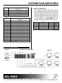
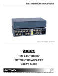
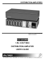
DISTRIBUTION AMPLIFIERS
MANUAL PART NUMBER: 400-0018-003
PRODUCT REVISION: 0
DA1406WM
1-IN, 6-OUT MAC
DISTRIBUTION AMPLIFIER
USER’S GUIDE
DISTRIBUTION AMPLIFIERS
INTRODUCTION
TABLE OF CONTENTS
Page
Thank you for purchasing the DA1406WM
Distribution Amplifier. We are sure you will find it a
reliable and useful product.
PRECAUTIONS / SAFETY WARNINGS ...............2
GENERAL ................................ .......................... 2
Superior performance for the right price backed by
solid technical and customer support is what we
have to offer.
INSTALLATION................................ ..................2
CLEANING................................ ......................... 2
FCC / CE NOTICE ................................ .............2
The product you are holding in your hands is
designed using state-of-the-art technology and is
superior to anything available on the market. You
will find this and our other products reliable, long
lasting, and simple to operate.
ABOUT YOUR DISTRIBUTION AMPLIFIER .........3
TECHNICAL SPECIFICATION .............................. 3
DESCRIPTION OF DA1406WM ............................ 4
We are committed to providing our customers with
solutions to the most demanding audio-visual
installations at very competitive pricing.
INPUT AND OUTPUTS ................................ ......4
BOOT UP SWITCHES ................................ .......5
APPLICATION DIAGRAM ................................ .....5
We appreciate your selection of our products and
are confident that you will join the ranks of our
many satisfied customers throughout the world.
INSTALLING YOUR DISTRIBUTION
AMPLIFIER................................ ............................ 6
OPERATION ................................ ......................... 6
ACCESSORIES................................ ..................... 7
This manual covers:
FREQUENTLY ASKED QUESTIONS.................... 7
DA1406WM - 1-in, 6-out MAC Distribution
Amplifier
TROUBLESHOOTING GUIDE .............................. 8
ALTINEX POLICY ................................ .................8
LIMITED WARRANTY................................ ........8
RETURN POLICY ................................ ..............8
CONTACT INFORMATION ................................ 8
1
DISTRIBUTION AMPLIFIERS
PRECAUTIONS / SAFETY WARNINGS
•
1
Please read this manual carefully before using your
DA1406WM Distribution Amplifier. Keep this
manual handy for future reference. These safety
instructions are to ensure the long life of your
DA1406WM and to prevent fire and shock hazard.
Please read them carefully and heed all warnings.
•
1.1 GENERAL
•
Unauthorized personnel shall not open the unit
since there are high-voltage components inside.
•
•
Qualified Altinex service personnel, or their
authorized representatives must perform all
service.
•
1.2 SAFETY GUIDELINES FOR THE RACKMOUNTING OF THE DA1406WM
• Maximum operating ambient temperature is 35
(degrees C).
•
1.4 CLEANING
• Unplug the DA1406WM power cord before
cleaning. Clean surfaces with a dry cloth. Never
use strong detergents or solvents such as
alcohol or thinner. Do not use a wet cloth or
water to clean the unit.
Never restrict the air flow through the devices’
fan or vents.
• When installing equipment into a rack, distribute
the units evenly. Otherwise, hazardous
conditions may be created by an uneven
weight distribution.
•
Connect the unit to a properly rated supply
circuit.
•
Reliable Earthing (Grounding) of RackMounted Equipment should be maintained.
Do not place heavy objects on top of the
DA1406WM. If the DA1406WM is to be mounted
to a table or wall, use only Altinex made
mounting accessories like brackets ( DA1293FC
and DA1294FC) and cables for optimum setup.
To turn off the main power, be sure to remove
the cord from the power outlet. The power outlet
socket should be installed as near to the
equipment as possible, and should be easily
accessible.
Do not pull the power cord or any cable that is
attached to the DA1406WM Distribution
Amplifier.
If the DA1406WM Distribution Amplifier is not
used for an extended period, disconnect the
power cord from the power outlet.
1.5 FCC / CE NOTICE
• This device complies with Part 15 of the FCC
Rules. Operation is subject to the following two
conditions: (1) This device may not cause
harmful interference, and (2) this device must
accept any interference received, including
interference that may cause undesired
operation.
1.3 INSTALLATION
• For best results, place the DA1406WM
Distribution Amplifier on a flat, level surface in a
dry area away from dust and moisture.
• To prevent fire or shock, do not expose this unit
to rain or moisture. Do not place the
DA1406WM Distribution Amplifier in direct
sunlight, near heaters or heat radiating
appliances, or near any liquid. Exposure to
direct sunlight, smoke, or steam can harm
internal components.
• Handle the DA1406WM Distribution Amplifier
carefully. Dropping or jarring can damage
internal components.
•
2
This equipment has been tested and found to
comply with the limits for a Class A digital
device, pursuant to Part 15 of the FCC Rules.
These limits are designed to provide reasonable
protection against harmful interference when the
equipment is operated in a commercial
environment. This equipment generates, uses,
and can radiate radio frequency energy and, if
not installed and used in accordance with the
instruction manual, may cause harmful
interference to radio communications. Operation
of this equipment in a residential area is likely to
cause harmful interference in which case the
user will be required to correct the interference
at his own expense.
DISTRIBUTION AMPLIFIERS
•
Any changes or modifications to the unit not
expressly approved by Altinex, Inc. could void
the user’s authority to operate the equipment.
ABOUT YOUR DISTRIBUTION AMPLIFIER
MECHANICAL
DA1406WM
Material
0.1” Al
Finish
Gray
Top Panel
Lexan
Height (inches)
1.75in (44mm)
Width (inches)
8.50in (216mm)
Depth (inches)
4.50in (114mm)
Weight (pounds)
2.0lbs (0.91kg)
Ship Weight (pounds)
3.2lbs (1.45kg)
T° Operating
10°C-35°C
T° Maximum
50°C
Humidity
90% non-condensing
MTBF (calculations)
40,000 hrs
Table 2. DA1406WM Mechanical
2
The DA1406WM is a 1-in 6-out MAC distribution
amplifier designed to connect a single computer
video source to as many as six scan rate
compatible displays. The DA1406WM will pass an
analog video signal up to 1.5 V p-p. Using AGC
sync circuitry, the DA1406WM converts incoming
TTL sync levels to a standard 4V p-p level.
All input and output connectors are 15-pin D
female. This provides superior durability, as the
pins on male connectors can be easily bent
disabling the entire unit. A male to male MAC cable
will typically be required for connection between the
computer and the input to the DA1406WM.
ELECTRICAL
DA1406WM
Input Video Signal
Analog Signal
1.5V p-p max
Impedance
75 Ohms
Input Sync Signal
Horizontal, Vertical, & C-Sync
TTL(+/-)
Sync on Green
-0.3V
Impedance
10 k Ohms
Output Video Signals
Analog Signal
Gain of 1.05 (+/-5%)
Fall/Rise Time (ns)
1.4
Impedance
75 Ohms
Output Sync Signal
Composite Sync
TTL(+/-)
Sync on Green
-0.3V
Impedance
22 Ohms
Frequency Compatibility
Typical Video Bandwidth
380 MHz
Minimum Video Bandwidth
350 MHz
Horizontal
15-200 kHz
Vertical
47-180 Hz
DC
Coupling
-40dB @ 10 MHz
Cross-talk
Power
Internal Power Adapter
90-140/200-240 V
10 watts max.
Power Consumption
Table 3. DA1406WM Electrical
Four ID bit switches allow a user to boot up a
computer at a variety of monitor settings. Though
primarily designed for use with displays using
15-pin D (MAC-type) connectors, the DA1406WM
can pass RGBHV, RGBS, and RGsB format
signals. Adapter cables may be necessary to
accomplish the appropriate connector change.
The DA1406WM is great for desktop use, but can
also be rack-mounted using optional hardware.
TECHNICAL SPECIFICATIONS
FEATURES/DESCRIPTION
GENERAL
Input
Input Connector
Output
Output Connectors
Compatibility
3
DA1406WM
1
15-pin D Female
6
Six 15-pin D Female
MAC, Power MAC,
MAC Quadra, high
resolution RGBHV,
RGBS, RGsB and
RsGsBs
Table 1. DA1406WM General
3
DISTRIBUTION AMPLIFIERS
DESCRIPTION OF DA1406WM
4
PIN No.
4.1 INPUT AND OUTPUTS
Using female 15-pin D (MAC-type) connectors
on all input and output connectors, the
DA1406WM can be used with readily available
MAC-type cables. If desired, the input and/or
outputs of the DA1406WM can be easily
adapted to 5-BNC connectors to allow it to be
used with RGsB, RGBS, or RGBHV signal types
as well. This requires the use of Altinex MS8100
series adapter cables (15 pin to 5 BNC).
1
2
3
4
5
6
7
8
9
10
11
4
Input signals on 15-pin D female
connector
Ground
Red
Composite Sync
Switch 1 (Grounded when switch is ON
Green
Ground
Switch 2 (Grounded when switch is ON
No connection
Blue
Switch 3 (Grounded when switch is ON
Ground
DISTRIBUTION AMPLIFIERS
PIN No.
Input signals on 15-pin D female
connector
12
Vertical Sync
13
Ground
14
Ground
15
Horizontal Sync
Table 4. The DA1406WM Input pin-out
4.2 BOOT UP SWITCHES
Some Video cards require the proper sense ID
pins to determine the boot up mode. Sense pins
are usually present on MAC video cards. When
distribution amplifiers are used, the local monitor
(monitor connecting directly to the computer) is
no longer available. To insure the proper boot up
of the computer, the DA1406WM has dipswitches located on the back panel of the unit.
PIN No.
Output signals on 15-pin D female
connector
1
Ground
2
Red
3
Composite Sync
4
No connection
5
Green
6
Ground
7
No connection
8
No connection
9
Blue
10
No connection
11
Ground
12
Vertical Sync
13
Ground
14
Ground
15
Horizontal Sync
Table 5. The DA1406WM Outputs pin-out
APPLICATION DIAGRAM
SWITCH
FUNCTION
ON
OFF
1
Pin 4
GND
OPEN
2
Pin 11
GND
OPEN
3
Pin 12
GND
OPEN
4
Not used
Table 6. Description dip-switches of the DA1406WM
5
5
DISTRIBUTION AMPLIFIERS
INSTALLING YOUR DISTRIBUTION
AMPLIFIER
OPERATION
6
Step 1.
Make sure that the power input is set to
the proper AC voltage in your country.
An incorrect setting can result in
equipment damage not covered by
warranty. If the power input voltage
needs to be changed, remove the fuse
portion of the power entry module and
change the location of the fuse. Note
that the correct voltage is visible through
the voltage designation window.
Step 2.
Connect the power cord to the unit and
plug it into the power outlet. The power
indicator LED on the front and back
panel will light. This indicates that the
unit is operational.
Step 3.
Connect a cable from the computer to
the input channel of the amplifier. Then
connect the output channels of the
amplifier to the display devices (i.e.
monitors or projector)
Step 4.
If the image is less than perfect check
all the connections. The unit is very
reliable and seldom will this be the
cause of malfunction. Poor quality
cables may often degrade the
performance of the product. Make sure
that the cables used are coaxial cables
and that all pins are in good condition.
7
The settings of the DA1406WM Distribution
Amplifier can be adjusted using Boot switches as
described in Section no. 4. There are no other
adjustments necessary to operate the unit. The
DA1406WM will operate successfully as long as
cables are attached properly and other
specifications are followed.
CONGRATULATIONS! YOU ARE DONE.
If you experience any problems, please call
1-800-258-4623 or 1-714-990-2300 for
international calls.
6
DISTRIBUTION AMPLIFIERS
ACCESSORIES
Model No.
TM1271
TM1272
TM1273
TM1274
DA1293RM
DA1294RM
CB3403MR
CB3406MR
CB3415MR
CB3425MR
CB3450MR
CB3475MR
CB34100MR
CB34150MR
CB3603MR
CB3606MR
CB3615MR
CB3625MR
CB3650MR
CB3675MR
CB36100MR
CB36150MR
MS8103CA
MS8111CA
PC5301US
PS5302UK
PS5303AU
PS5304GR
8
FREQUENTLY ASKED QUESTIONS
Description
TABLE MOUNT BRACKET
1 U High, ½ rack units
1 U High, ½ rack units w/Computer
Input
1 U High, ½ rack units w / Computer +
A / V Inputs
1 U High, ½ rack units w / Computer +
A / V + Power Inputs
RACK MOUNTING ACCESSORIES
19”-1U Rack Mount Shelf (2- Units)
19”-1U Rack Mount Ears for single unit.
MAC MALE TO MALE CABLES
(15-PIN D TO 15-PIN D)
3 ft
6 ft
15 ft
25 ft
50 ft
75 ft
100 ft
150 ft
MAC MALE TO FEMALE CABLES
(15-PIN D TO 15-PIN D)
3 ft
6 ft
15 ft
25 ft
50 ft
75 ft
100 ft
150 ft
MAC TO RGB ADAPTOR CABLES
15 pin D Male to 4 BNC Male, 6ft
15 pin D Male to 5 BNC Male, 15ft
POWER CABLES
Power cable for US
Power cable for England
Power cable for Australia
Power cable for Germany
No:
1
Question
What is a
Distribution
Amplifier?
2
May I have
on the
outputs of
the
DA1406WM
as high
resolution
RGBHV or
RGBS
format
signals if the
input is on
the MAC
format
signal?
What If I
don’t use all
6 outputs of
the
DA1406WM?
3
3
4
7
9
Answer
A Distribution Amplifier is a
device that allows you to
connect a single video
source to multiple display
devises, such as monitors or
projectors used in
presentation applications.
No. The Distribution
Amplifier doesn’t change a
signal resolution format – it
only passes it through. It is
critical to insure that the
display equipment used in a
system is compatible with
the source equipment in
terms of signal resolution.
It is not necessary to use all
six outputs and it is not
necessary to terminate
unused outputs, because
you have six individually
buffered outputs.
What is
Buffered output means that
meant by
the output signal is isolated
buffered
from the input signal. The
output?
loaded output does not
affect the input, or any other
output on the device. A
buffered output may vary in
terms of the gain or peaking
adjustments made to the
video signal.
Which type
The DA1406WM can pass
of format
MAC, Power MAC, and MAC
signal may I
Quadra. May also be used to
pass through pass high resolution
the
RGBHV, RGBS, RGsB, and
DA1406WM? RsGsBs format signals.
DISTRIBUTION AMPLIFIERS
TROUBLESHOOTING GUIDE
11.2 RETURN POLICY
It is very important that you receive products that
you have ordered and that this product fulfills
your need. In the unlikely event that an Altinex
product needs to be returned please follow the
policies below:
10
We have carefully tested and have found no
problems in the supplied DA1406WM unit;
however, we would like to offer the following
suggestions:
•
Check to insure the power input is set to proper
AC voltage. That the correct voltage is visible
through the voltage designation window.
•
Please make sure that the input amplitude
analog signal is less than 1.5V.
•
Please use Altinex supplied external adapter
(9V, 500mA).
•
Please make sure that proper qualities of cables
are used. We recommend Altinex made cables
for best results.
•
Altinex will accept product returns for a period of
30 days from authorized Altinex dealers.
Products should be returned in an unopened
package.
If a product has been opened, the restocking
fees will apply. For the restocking fee amount,
please contact an Altinex Sales Representative.
If the product is in your possession for more
than 30 days, the restocking fees will apply.
Altinex will not accept any returns on cables or
custom products.
If the problem shows up after continuous usage
at higher voltage, higher temperature, higher
humidity, or at other extreme environmental
conditions, please correct the problem.
ALTINEX POLICY
If your product is in warranty and needs service,
contact the Altinex Sales Department for an
RMA (Return Material Authorization). Products
returned without an RMA number may
experience a delay in service.
11
If your product is out of warranty and needs
service, contact the Altinex Sales Department
for an RMA (Return Material Authorization).
Products returned without an RMA number may
experience a delay in service. The service
charges will be quoted to you before the actual
repairs are done.
11.1 LIMITED WARRANTY
Altinex warrants that its products and cables are
free from defects in materials under normal use
and service. This warranty is limited to repairing
at company’s factory any part or parts of the
product, which upon company’s examination
shall disclose to be, thus defective. Products
considered defective shall be returned to
company with transportation charges pre-paid
within 2 years or (90 days for cables) from date
of shipment to the purchaser. The warranty is
expressly instead of all other warranties
expressed or implied. Altinex neither assumes
nor authorizes any other person to assume for it
any other liability in connection with the sale of
the products. This warranty shall not apply to
any product that shall have been repaired or
altered outside of company’s factory in any way
so as, in its judgment, to affect its stability or
reliability, or that has been subject to misuse,
negligence or accident.
11.3 CONTACT INFORMATION
Sales Department
Phone:
714-990-2300
Fax:
714-990-3303
Accounting Department
Phone:
714-990-6088
Fax:
714-990-5778
8