1
IFSI
CNR
MEX ASPERA-3
ASPERA-3 EGSE User Manual
Ref.:
Issue:
Date:
Page:
ME-ASP-MA-0002
Issue 1 Rev. 4
15/2/2002
Page 1 of 58
ASPERA-3 EGSE User Manual
Name and function
Prepared by:
Riccardo Cerulli-Irelli
Verified by:
Herman Andersson, EM
Approved by:
Stas Barabash, Co-PI
Date
Signature
MEX ASPERA-3
IFSI
CNR
ASPERA-3 EGSE User Manual
Ref.:
Issue:
Date:
Page:
ME-ASP-MA-0002
Issue 1 Rev. 4
15/2/2002
Page 2 of 58
Distribution List:
IRF
Stas Barabash
Herman Andersson
FMI
Tuukka Sales
IFSI
Stefano Orsini
Anna Milillo
Alessando Mura
Andrea Mattana
Change Record:
Version
Date
Issue 1, Rev 3
Issue 1, Rev 3
Issue 1, Rev 4
5/3/2001
5/3/2001
15/2/2002
Changed
Paragraphs
4, 5
3.2
2.2
Remarks
Removed (was empty)
Written (was empty)
Added powConvrc configuration file
Reference documents
Document
Reference
RD1
Name
External interfaces for the Rosetta CCS
Reference
RO-TER-IS-4001
Issue 1.5
IFSI
CNR
MEX ASPERA-3
ASPERA-3 EGSE User Manual
Acronyms
ADC
APID
CAT
CCS
CNR
CPU
DPU
Analog to Digital Converter
Application Process IDentification
Packet CATegory
Central Check-out System
Consiglio Nazionale delle Ricerche
Control Processing Unit
Digital Processing Unit
DSP
EGSE
ESA
ILT
HK
HW
Digital Signal Processor
Electrical Ground Support Equipment
European Space Agency
Instrument Level Test
HouseKeeping
HardWare
ID
I/F
IFSI
MOC
NA
OBDH
PID
RDx
S/C
SDM
SCOE
SLT
Identification
Interface
Istituto di Fisica dello Spazio Interplanetario
Mission Operation Center
Not Applicable
On Board Data Handling
Process ID
Reference Document x [RDx]
Spacecraft
Science Display Module
System Check-Out Equipment
System Level Test
TBC
TBD
TBW
TC
TM
To Be Confirmed
To Be Defined
To Be Written
Telecommand
Telemetry
Ref.:
Issue:
Date:
Page:
ME-ASP-MA-0002
Issue 1 Rev. 4
15/2/2002
Page 3 of 58
IFSI
CNR
1
MEX ASPERA-3
ASPERA-3 EGSE User Manual
Ref.:
Issue:
Date:
Page:
ME-ASP-MA-0002
Issue 1 Rev. 4
15/2/2002
Page 4 of 58
General Description ...........................................................................................................................................5
1.1 SCOE ...........................................................................................................................................................6
1.2 MEXILT ......................................................................................................................................................6
1.3 S/C simulator ...............................................................................................................................................6
1.4 SDM ............................................................................................................................................................7
1.5 Instrument Interface.....................................................................................................................................8
1.6 Stimulator Interface .....................................................................................................................................8
1.7 User Interface ..............................................................................................................................................8
1.8 Network Interface ........................................................................................................................................9
1.9 Software Description ...................................................................................................................................9
2
Egse Configuration ..........................................................................................................................................10
2.1 Directory tree .............................................................................................................................................10
2.2 Run Time Configuration............................................................................................................................12
2.3 Instrument/System Level Test ...................................................................................................................14
2.4 Instrument Level Test EGSE .....................................................................................................................14
2.4.1
Physical configuration......................................................................................................................15
2.4.2
Software ...........................................................................................................................................16
2.5 System Level Test EGSE...........................................................................................................................18
2.5.1
Physical configuration......................................................................................................................18
2.5.2
Software ...........................................................................................................................................19
3
Operations ........................................................................................................................................................21
3.1 Instrument Level Test Operations..............................................................................................................21
3.1.1
Program setup ..................................................................................................................................21
3.1.2
SCOE interface................................................................................................................................21
3.1.3
Command List..................................................................................................................................26
3.1.4
Archiving .........................................................................................................................................38
3.1.5
Playback ...........................................................................................................................................39
3.2 System Level Test Operations ...................................................................................................................40
3.2.1
Program Setup..................................................................................................................................40
3.2.2
SCOE Interface ..............................................................................................................................40
3.2.3
Command List..................................................................................................................................41
3.2.4
Commands sequence ........................................................................................................................45
4
APPENDIX......................................................................................................................................................46
4.1 External Electronic Schematics .................................................................................................................46
4.2 ASPERA High Level Command ILT ........................................................................................................51
4.3 ASPERA High Level Command SLT .......................................................................................................52
IFSI
CNR
MEX ASPERA-3
ASPERA-3 EGSE User Manual
Ref.:
Issue:
Date:
Page:
ME-ASP-MA-0002
Issue 1 Rev. 4
15/2/2002
Page 5 of 58
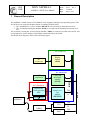
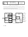
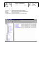
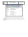
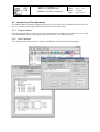
1 General Description
The ASPERA 3 EGSE consists of two IBM-PC class computers running Linux operating system. The
first PC hosts two programs modules linked via standard TCP/IP socket:
• The “Instrument Level Test” module (MEXILT) to be used only at instrument level test
• The “Command and Display Module (SCOE) to be used both at instrument and system level
test.
The second PC, hosting the “science Display Module” (SDM), is connected via NFS to the SCOE, and
is responsible for science display of the telemetry data archived by the SCOE.
The EGSE block diagram is shown in the following figure.
PC Linux OS
PC
peripherals
Science
Display
Module
(SDM)
PC Linux OS
PC
peripherals
S/C Simulator
Pwr & Relays
Instr.Level
Test
Module
(MEXILT)
TM
TC
ASPERA 3
TM
CCS
OBDH
TC
TM
MOC
TCP/IP
DSP Board
Clock generator
ADC
TCP/IP
Command
& Display
Module
(SCOE)
IFSI
CNR
1.1
MEX ASPERA-3
ASPERA-3 EGSE User Manual
Ref.:
Issue:
Date:
Page:
ME-ASP-MA-0002
Issue 1 Rev. 4
15/2/2002
Page 6 of 58
SCOE
The SCOE module is responsible for command sequence generation and housekeeping data display.
This module, during the instrument level tests, is connected to MEXILT using the same (Internet
domain stream socket) protocol used by CCS in order to be used with only minor modifications at
system level test. At system level test this module is connected to CCS.
1.2
MEXILT
The MEXILT module is connected to the ASPERA instrument through a S/C simulator board, which
provide the OBDH hardware interface. The MEXILT module provides the basic OBDH-CCS emulation
and is responsible for TLM/TLC serialization, verification and transmission, and is command controlled
by the SCOE module linked via TCP/IP connection. Due to this inter process communication scheme,
the two program modules may run on different computers connected to Internet.
1.3
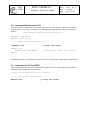
S/C simulator
The S/C simulator is designed around the TI 320C54x DSKplus board plus a simple external electronic
board for signal generation and OBDH compliant interfaces.
The main characteristics of the TI 320C54x board (shown in fig 5.1.2-2) are:
• One TMS320C542 ('C542) 40 MHz enhanced fixed-point DSP
• 40 MIPS (25-ns instruction cycle time)
• 10K words of dual-access RAM (DARAM)
• 2K words boot ROM
• One time-division-multiplexed (TDM) serial port
• One buffered serial port (BSP)
• One host port interface (HPI) for PC-to-DSP communications
• One on-chip timer
• Programmable, voice-quality TLC320AC01 (DAC, ADC interface circuit)
• I/O expansion bus and control signals for external designs
IFSI
CNR
MEX ASPERA-3
ASPERA-3 EGSE User Manual
Ref.:
Issue:
Date:
Page:
ME-ASP-MA-0002
Issue 1 Rev. 4
15/2/2002
Page 7 of 58
Figure 1 – The TI 320C54x DSKplus board
This board connect to the (MEXILT) module through the PC parallel port at a speed of ~ 100 Kbytes/s.
At start up the MEXILT module download the (C language) program to the DSK. The DSK receive the
TC packets and local instruction and send TM packets from/to ILT PC.
The figure 1 shows the overall S/C simulator concept, “external electronic” schematics are in Appendix.
DSK
14 bit
A/D
Extern Data
Extern Addr
To ILT
parallel port Commands
& TM
Circular
buffers
Pulse
generator
Serial
Port
16 bit In Port
External
Electronic
Memory Load
Data
16 bit Out Port
2 x 263
S-
Signal
generation
TM
TC
Interrupt
controller
Continuous
SL
Figure 5.1.2-3 – The S/C simulator concept
1.4
SDM
Serial
Telemetry Data
Serial Data
Transfer Clock
Memory Load
Sampling
Serial Telemetry
Sampling
IFSI
CNR
1.5
MEX ASPERA-3
ASPERA-3 EGSE User Manual
Ref.:
Issue:
Date:
Page:
ME-ASP-MA-0002
Issue 1 Rev. 4
15/2/2002
Page 8 of 58
Instrument Interface
The EGSE will be connected only to the ASPERA-3 Main Unit of the ASPERA-3 experiment, and this
connection is realised through the spacecraft simulator interface. This interface surface will be active in
all operation foreseen for the EGSE. The spacecraft interface will be simulated by the EGSE, and be
fully compliant with the spacecraft bus system (including the connectors). The spacecraft power
simulator, included in the S/C simulator unit, will provide power and switching functions to the
ASPERA-3 experiment. The power supply will overvoltage and current limiting capabilities. The power
will be interfaced to the ASPERA-3 through one connector.
The EGSE consists of an RTU simulator for controlling the RPC and for acquiring the housekeeping
and science TM information. The science data may contain also memory dumps, or other engineering
data. The EGSE will acquire through the spacecraft communication interface the telemetry packets, the
EGSE will simulate the rate at which the telemetry packets are acquired from ASPERA-3 instrument,
including multiple telemetry rates.
All command to the instrument will be via the spacecraft serial interface. The interface simulator is a
part of the EGSE. The EGSE will simulate the distribution of synchronisation and timing information.
For the ASPERA-3 experiment there will be two types of data that will be acquired by the EGSE:
housekeeping and science. The science data may contain memory dumps, or other engineering data. For
controlling the Spacecraft Powered Thermistor, a simulator of the Onboard Monitoring System (OMS)
is implemented in the S/C simulator (ADC etc.).
1.6
Stimulator Interface
The ASPERA-3 instrument will not use any external or internal stimuli and due to this there is no
stimuli interface of the EGSE.
1.7
User Interface
The user interface of the EGSE/S is the keyboard, mouse and the monitor’s display. One adequately
sized monitor will be available for tabular and graphical data display. Optionally other bus monitors
may be required, their operation will be supported, but the additional monitors are not part of the EGSE.
The EGSE is capable of displaying decommutated data products from the sensors as the data is being
acquired in real time mode of operation (when the EGSE is directly receiving data from the ASPERA3). The EGSE will be capable to analyse data recorded previously, the amount of historical data
available is limited to the amount of temporary data storage available and to the amount of data
accessible via the networks. It will be possible to display replayed plots in conjunction with the real
time data.
There will be capability to execute single commands and data loads from the EGSE. Hazardous
commands shall have an extra level of protection to allow the user extra opportunities to abort sending
them. There will be a capability to execute automatic test sequences by the EGSE, such as data
selection and limit verification, etc.
The EGSE will record in an ASCII file the history of events that occurred during its operation. Any
events that are pertinent to instrument operations shall be logged. Optionally other PCs for monitoring
the data exchange (bus monitors) may be required. Their operation will be supported, but they are not
part of the EGSE.
IFSI
CNR
1.8
MEX ASPERA-3
ASPERA-3 EGSE User Manual
Ref.:
Issue:
Date:
Page:
ME-ASP-MA-0002
Issue 1 Rev. 4
15/2/2002
Page 9 of 58
Network Interface
During its operation the EGSE will be connected both to LAN’s and WAN’s. It is foreseen that the
EGSE will analyse data obtained via a network during the flight operation phase, or that the data
storage will be organised via network. The EGSE will support these functions. During system level
tests the EGSE will be connected to the central checkout system, provided by the project. The Central
Checkout System (CCS) is not a part of the EGSE. It is assumed that the communication between the
EGSE and the CCS shall use the network interface.
1.9
Software Description
The two SW modules, written in C++, will run under the Linux operating system (Slakware
distribution). The SCOE module will use the KDE-Qt X Library and will communicate with MEXILT
module using BSD socket communication protocol. The user interface will be a graphical windows
interface.
The S/C simulator SW is written in C language and downloaded to the DSK board from MEXILT
module at start up.
IFSI
CNR
MEX ASPERA-3
ASPERA-3 EGSE User Manual
Ref.:
Issue:
Date:
Page:
ME-ASP-MA-0002
Issue 1 Rev. 4
15/2/2002
Page 10 of 58
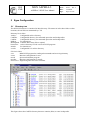
2 Egse Configuration
2.1
Directory tree
The full EGSE software is contained in /Mex directory. File names in italic shows links to other
locations, the real files are maintained by CVS.
Directory list in /Mex:
Archive
Configurable archive directory
CmdFiles
Configurable directory for commands procedure and lookup tables
CmdLut
Configurable directory for commands procedure and lookup tables
DSProg
For internal use
MemUpload Contains DPU binary files to upload
binArchive Archive directory for old version of EGSE programs
include
For internal use
scArch
Configurable S/C archive directory
File list in /Mex:
scoe
Main EGSE program for sending telecommands and receiving telemetry.
scoerc
Run time configuration for scoe.
mexilt
Spacecraft simulator program.
mexiltrc
Run time configuration for mexilt.
PowConvrc Engineering unit conversion constants
This figure shows the CmdFile directory that now contains (links) to some lookup table .
MEX ASPERA-3
IFSI
CNR
ASPERA-3 EGSE User Manual
File list in /Mex:/CmdLut
LocProc.txt
Macro.txt
Rpropkt.txt
Telecommand.txt
Pseudo programming language definitions.
Macro expansion file. See Macro command chapter.
CCS protocol commands.
High level command file. See relevant chapter.
Ref.:
Issue:
Date:
Page:
ME-ASP-MA-0002
Issue 1 Rev. 4
15/2/2002
Page 11 of 58
IFSI
CNR
2.2
MEX ASPERA-3
ASPERA-3 EGSE User Manual
Ref.:
Issue:
Date:
Page:
ME-ASP-MA-0002
Issue 1 Rev. 4
15/2/2002
Page 12 of 58
Run Time Configuration
The 3 files scoerc powConvrc and mexiltrc contains initial configuration read at run time
File location: /Mex/scoerc
Link to
/users/cerulli/cpp/scoe/scoe/scoerc
# SCOE Configuration file File. Roma 23.5.00
[Directory]
#-------- TM archive directory
TLMARCH=/Mex/Archive/
#-------- Command archive directory
CMDARCH =/Mex/Archive/
#-------- Command directory
CMDFILES =/Mex/CmdFiles/
#-------- Load memory binary files directory
BINFILES =/Mex/MemUpload/
#-------- TeleCommand acronym file at ILT
TLCFILE =/Mex/CmdLut/TeleCommand.txt
#-------- TeleCommand macro file at ILT
MACROFILE=/Mex/CmdLut/Macro.txt
#-------- TeleCommand acronym file at SLT
TLCFILESLT =/Mex/CmdLut/TeleCommandSLT.txt
#-------- TeleCommand macro file at SLT
MACROFILESLT=/Mex/CmdLut/MacroSLT.txt
#-------- RPRO macro file
RPROFILE=/Mex/CmdLut/Rpropkt.txt
#-------- Local procedure pseudo instruction file
LPROCTBL=/Mex/CmdLut/LocProc.txt
#-------- Command list include file
CMDTBL=/Mex/include/dspcmtbl.h
[IntConst]
#-------- S/C simulator model (0 .. 2)
SIMODEL=1
#-------- Socket port number
PORT=6010
#-------- Seconds to reopen TC archive
SEC_TO_NEW_ARCTC=3600
#-------- Seconds to reopen TM archive
SEC_TO_NEW_ARCTM=3600
MEX ASPERA-3
IFSI
CNR
ASPERA-3 EGSE User Manual
File location: /Mex/powConvrc
Ref.:
Issue:
Date:
Page:
Link to
/users/cerulli/cpp/scoe/scoe/ powConvrc
#####################################
# Power conversion configuration file
#####################################
#
# The conversion is X= AY + B with
# Y=byte/word value, X=value in engineering unit
# In this file are the A and B coefficients for the various
# tabbed panels in the Status/HK windows
# Power panel
[Power]
#-------AI30=0.1176
BI30=0.0
#-------AI5=0.0196
BI5=0.0
#-------AVM12=-0.047
BVM12=0.0
#-------AVM5=-0.0196
BVM5=0.0
#-------AV5=0.0196
BV5=0.0
#-------AV12=0.047
BV12=0.0
#-------AV30=0.1176
BV30=0.0
(astatus7)
I30
I5
VM12
VM5
V5
V12
V30
#------- Scanner panel
[ScanPos]
#------- pos to degree conversion
ADEG=0.772
BDEG=0.0
File location: /Mex/mexiltrc
(astatus6)
Link to
/users/cerulli/cpp/mexilt/mexilt/mexiltrc
# mexilt Configuration file File
[String]
#-------- TM archive directory
FILARCH=/Mex/scArch/
#-------- Socket server
SERVERHOST=127.0.0.1
[IntConst]
#-------- Socket port number
PORT=6010
#-------- timeout for requested ack
ACKATIMOUT=20
ME-ASP-MA-0002
Issue 1 Rev. 4
15/2/2002
Page 13 of 58
IFSI
CNR
2.3
MEX ASPERA-3
ASPERA-3 EGSE User Manual
Ref.:
Issue:
Date:
Page:
ME-ASP-MA-0002
Issue 1 Rev. 4
15/2/2002
Page 14 of 58
Instrument/System Level Test
The SCOE module is used both at instrument and system level test. The few differences in the two
configurations are resolved at compile time commenting/uncommenting the constant variable ILT
found in
/users/cerulli/cpp/scoe/scoe/configura.h
#ifndef __320c542_H__
#define __320c542_H__
/* --- Conditional compilation --- */
//#define ILT
#ifndef ILT
#define NET_BYTE_ORDER
#endif
.. ..
.. ..
// Using ILT client
// Use net byte order (big endian)
The MEXILT and S/C sim modules are used only at ILT, while SDM is used in both configurations.
2.4
Instrument Level Test EGSE
In this configuration both the SCOE and MEXILT modules are used. The SCOE program must be
compiled with (defining) the ILT constant in
/users/cerulli/cpp/scoe/scoe/configura.h
/* --- Conditional compilation --- */
#define ILT
// Using ILT client
IFSI
CNR
MEX ASPERA-3
ASPERA-3 EGSE User Manual
Ref.:
Issue:
Date:
Page:
ME-ASP-MA-0002
Issue 1 Rev. 4
15/2/2002
Page 15 of 58
2.4.1 Physical configuration
The SCOE and MEXILT programs runs both on a single PC, and the Science Display Module (SDM)
run on a separate PC sharing (via NFS) with SCOE/MEXILT PC the telemetry archive directory
structure
Linux OS PC
SCOE
S/C sim
MEXIL
Printer Port
connection
SDM
ASPERA
MEX ASPERA-3
IFSI
CNR
ASPERA-3 EGSE User Manual
Ref.:
Issue:
Date:
Page:
ME-ASP-MA-0002
Issue 1 Rev. 4
15/2/2002
Page 16 of 58
Software
2.4.2
SCOE communicates with MEXILT through TCP/IP connection, the last communicates with S/C SIM
through the parallel port. The S/C SIM is connected to ASPERA3 via standard TM/TC interfaces.
SCOE/MEXILT PC communicates with the Science Display Module (SDM) PC sharing (via NFS) the
telemetry archive directory structure.
Server
Client
SCOE
Packetizer
Command &
Display
ILT
ILT
4 Oct
SDM
Data
MEXILT
TCP/IP (BSD) socket
RPRO
NFS
Packet
10-16 Oct
PDU
(78+32 Oct)
Packet
10-16 Oct
Data
NOT USED
CCS
IFSI
CNR
MEX ASPERA-3
ASPERA-3 EGSE User Manual
Ref.:
Issue:
Date:
Page:
ME-ASP-MA-0002
Issue 1 Rev. 4
15/2/2002
Page 17 of 58
2.4.2.1 SCOE
The SCOE program is the main EGSE interface. The program consists of an editor-like window used
to type, edit and send commands to MEXILT. Commands (one line per command) can be sent one by
one, or as a sequence at a defined time interval.
Instructions can’t be used inside a command file transmitted directly as with TXFILE command.
ASPERA 3 telemetry packets received by MEXILT can be displayed in tabular mode, and the
housekeeping packets are displayed in appropriate windows.
All ASPERA 3 telemetry packets can be stored in the archive directory for the SDM elaboration.
2.4.2.2 MEXILT
MEXILT program simulate the MEX spacecraft and is responsible to deliver to ASPERA the
telecommands received by SCOE and to deliver to SCOE the telemetry received by ASPERA.
MEXILT program consists of 3 concurrent threads:
• A thread responsible of TCP/IP communications with SCOE
• A thread responsible of continuous telemetry monitoring
• An execution thread interpreting and executing the SCOE commands
Commands received from SCOE are coded as a "packet" with:
• Word 1 = ID identify the command
• Word 2 = N
number of words to follow
• Word 3 = Data parameters (if any)
• . . . . . . . . . . . . . . . . . .
• Word N+2= Last parameter
The commands received from SCOE are divided in 3 types, defining the execution priority from high to
low.
The commands are stored in 3 different circular buffers
• Immediate commands
• Program commands
• Normal commands
Generally each command can belong to each of the 3 types.
Immediate commands are executed at the end of the current command execution phase.
Program commands are commands executed as a sequence. The sequence (i.e. the program) is formed
by standard commands plus a few "pseudo instructions" special commands, defining elementary
programming language statements (i.e. for loop, if statements, setting of program variables etc).
Normal commands are executed when no other command type is present.
IFSI
CNR
MEX ASPERA-3
ASPERA-3 EGSE User Manual
Ref.:
Issue:
Date:
Page:
ME-ASP-MA-0002
Issue 1 Rev. 4
15/2/2002
Page 18 of 58
2.4.2.3 SDM
2.5
System Level Test EGSE
In this configuration only the SCOE module is used. The SCOE program must be compiled without
(commenting) the ILT constant in
/users/cerulli/cpp/scoe/scoe/configura.h
/* --- Conditional compilation --- */
//#define ILT
// Using ILT client
To properly accept the time synchronization request from CCS, the “mode” of the system “date”
program must be changed (as super user) to:
chmod u+s /bin/date
2.5.1 Physical configuration
The SCOE and the Science Display Module (SDM) run on a separate PC sharing (via NFS) with the
telemetry archive directory structure
SDM
SCOE
CCS
Ref.:
Issue:
Date:
Page:
MEX ASPERA-3
IFSI
CNR
ASPERA-3 EGSE User Manual
ME-ASP-MA-0002
Issue 1 Rev. 4
15/2/2002
Page 19 of 58
2.5.2 Software
SCOE communicates with the ESA CCS through TCP/IP connection, and with the Science Display
Module (SDM) PC sharing, via a second network interface using TCP/IP NFS protocol, the telemetry
archive directory structure.
Server
Client
SCOE
NOT USED
Packetizer
Command &
Display
ILT
ILT
4 Oct
SDM
Data
MEXILT
TCP/IP (BSD) socket
RPRO
NFS
Packet
10-16 Oct
PDU
(78+32 Oct)
Packet
10-16 Oct
Data
CCS
IFSI
CNR
MEX ASPERA-3
ASPERA-3 EGSE User Manual
Ref.:
Issue:
Date:
Page:
ME-ASP-MA-0002
Issue 1 Rev. 4
15/2/2002
Page 20 of 58
2.5.2.1 SCOE
The SCOE program is the main EGSE interface. The program consists of an editor-like window used
to type, edit and send commands to the CCS. Commands (one line per command) can be sent one by
one, or as a sequence at a defined time interval.
ASPERA 3 telemetry packets received by CCS can be displayed in tabular mode, and the housekeeping
packets are displayed in appropriate windows.
All ASPERA 3 telemetry packets can be stored in the archive directory for the SDM elaboration.
2.5.2.2 SDM
IFSI
CNR
MEX ASPERA-3
ASPERA-3 EGSE User Manual
Ref.:
Issue:
Date:
Page:
ME-ASP-MA-0002
Issue 1 Rev. 4
15/2/2002
Page 21 of 58
3 Operations
The ASPERA EGSE functionalities are very similar at both Instrument Level Test (ILT) and System
Level Test (SLT). The functionalities consist essentially in sending single commands, commands
sequences and receiving telemetry.
The telemetry received may be selectively shown in tabular form, interpreted and shown in appropriate
windows (housekeeping), interpreted and used in command sequences. All the communications in/out
with the program may be archived on HD for playback or for higher level interpretation and display
done by the Science Display Module (SDM) on a different computer.
The paragraphs 3.1 describes in detail the operation at ILT, only the difference at SLT will be described
in paragraph 3.2.
3.1
Instrument Level Test Operations
3.1.1 Program setup
The SCOE programs used at ILT are scoe and mexilt. Both programs must be executed manually or via
the aspera script procedure. Links to the programs are in /Mex directory. For program configuration
see paragraph 2.4.
3.1.2 SCOE interface
The main EGSE interface is the scoe program. The program consists of an editor-like window used to
compose, edit and send commands to ASPERA via mexilt and S/C sim.
Each line in the editor window is a single case-insensitive command or a comment (beginning with ‘#’
or ‘;’ character). Text after ‘#’ or ‘;’ characters is ignored.
The text present on the window may be stored/retrieved to/from a file.
Commands lines can be sent one by one, or as a sequence at a defined time interval.
The following function-keys have a special meaning in the editor window:
•
•
•
The F9 (or Ctrl-Return) key sends to mexilt the current (where the cursor is) command line or
the block of lines selected with the mouse.
The F11 key sends to mexilt the current command line and moves the cursor to the next line,
empty and comment lines are ignored.
The F10 key sends to mexilt all the commands from the current line as a procedure (see the
following “commands sequences” paragraph).
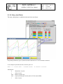
The figure shows the scoe main window with the set of initialisation commands executed automatically
at startup
IFSI
CNR
MEX ASPERA-3
ASPERA-3 EGSE User Manual
Ref.:
Issue:
Date:
Page:
ME-ASP-MA-0002
Issue 1 Rev. 4
15/2/2002
Page 22 of 58
The main configuration (modless) window, shown in the following figure, enables tabular windows
view of selected telemetry packets (up to 3 windows) and the archiving of all the telemetry packets
and/or commands.
Telemetry packet type=255 is reserved for private S/C simulator – scoe housekeeping and is archived in
a different file.
IFSI
CNR
MEX ASPERA-3
ASPERA-3 EGSE User Manual
Ref.:
Issue:
Date:
Page:
ME-ASP-MA-0002
Issue 1 Rev. 4
15/2/2002
Page 23 of 58
The display can be in dec or hex notation. A zero function/subfunction match all function/subfunction.
Archive files are stored in /Mex/Archive directory, and the files name indicate the creation time. A new
file is generated at fixed time as defined on /Mex/scoerc configuration file.
Up to 4 selected parameters may be plotted in a strip_chart windows (see section 3.1.6.3)
IFSI
CNR
MEX ASPERA-3
ASPERA-3 EGSE User Manual
Ref.:
Issue:
Date:
Page:
ME-ASP-MA-0002
Issue 1 Rev. 4
15/2/2002
Page 24 of 58
The next figure shows the multi-tabbed modless status/housekeeping window and the associated
command history frame. The full history can be stored in the TC archive file.
IFSI
CNR
MEX ASPERA-3
ASPERA-3 EGSE User Manual
Ref.:
Issue:
Date:
Page:
ME-ASP-MA-0002
Issue 1 Rev. 4
15/2/2002
Page 25 of 58
The ASPERA-3 housekeeping, transmitted as packet (3,25), is displayed in the tabbed windows.
The 8 (Status/HK windows) may be also selectively displayed as separate windows as shown in the
next figure
IFSI
CNR
MEX ASPERA-3
ASPERA-3 EGSE User Manual
Ref.:
Issue:
Date:
Page:
ME-ASP-MA-0002
Issue 1 Rev. 4
15/2/2002
Page 26 of 58
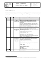
3.1.3 Command List
As a general rule all commands are case insensitive
Commands instructions are coded as a single text line beginning with the command ID (acronym) and
followed by parameters (if any):
ID [p1 p2 … pn]
ID and parameters are separated by ‘space’, ‘tab’ or ‘,’ (comma separator is not allowed in commands
at system level).
Characters following ‘;’ or ‘#’ are comments.
Lines of comments beginning with ‘#’ in column one, are saved in the command archive file.
Hexadecimal constants use the C coding convention (i.e. 0x5A5A).
There are five types of commands each type with its own definition file:
•
SCOE internal: These commands are used to set scoe program flags/variable (which remain
constant up to the next setting). The commands are defined in the first section of
/Mex/include/dspcmtbl.h and mustn’t be modified.
•
Low level: these commands are sent directly to the mexilt module and operate at the lowest
level. The commands are defined in second section of /Mex/include/dspcmtbl.h and mustn’t be
modified.
•
High level: these commands are composed by an acronym possibly followed by parameters and
generate a standard packet telecommand. The commands are translated in the scoe module to
low level commands and transmitted to mexilt. The commands are defined in
/Mex/CmdLut/TeleCommand.txt and are intended to be modified by the user.
•
Macro: these commands just substitute the macro acronym with whatever follows in the macro
definition line. A macro acronym may be followed by parameters in that case the parameters
are appended at the end of the macro translation line. The commands are defined in
/Mex/CmdLut/Macro.txt and are intended to be generated/modified by the user.
•
Command sequence instructions: these are pseudo programming-language instructions that
control the flow of commands in the sequences. The commands are defined in
/Mex/CmdLut/LocProc.txt and in /Mex/include/dspcmtbl.h and mustn’t be modified.
The following flow diagram shows the command verification and implementation algorithm
Ref.:
Issue:
Date:
Page:
MEX ASPERA-3
IFSI
CNR
ASPERA-3 EGSE User Manual
ME-ASP-MA-0002
Issue 1 Rev. 4
15/2/2002
Page 27 of 58
Command decoding diagram
Command = ID [p1 ... pn]
Check ID with MACRO defined in file
Macro.txt
N
Substitute ID with macro definition and append the original
parameters. The command is still in the general form:
command=IDx [a1 .. an] [p1 .. pn]
where IDx [a1 .. an] is the original ID macro expansion
Y
Found
Check ID with SCOE command
SEQUENCE pseudo instructions in
LocProc.txt
N
Y
Set SCOE
sequence control
Found
Exit
Check ID with SCOE INTERNAL
command defined in file dspcmtbl.h
N
Y
Found
Set SCOE internal
parameter
Exit
Check ID with LOW LEVEL command
defined in file dspcmtbl.h
N
Y
Found
Check ID with HIGH LEVEL command
defined in file TeleCommand.txt
N
Y
Found
Build the ASPERA
packet (PUS)
Substitute ID with the
MEXILT numeric
identifier
ERROR
Comunicate to user:
WRONG ID
Build up the ILT
protocol
Transmit command to
MEXILT module
Exit
MEX ASPERA-3
IFSI
CNR
ASPERA-3 EGSE User Manual
Ref.:
Issue:
Date:
Page:
ME-ASP-MA-0002
Issue 1 Rev. 4
15/2/2002
Page 28 of 58
3.1.3.1 SCOE internal
This first block of commands is used internally to the SCOE program. These commands are used to set
internal flags/variable (which remain constant up to the next setting) or check the telemetry data
(VERTM).
ID
IMME
PROG
NORM
ASAP
N. Par
0
0
0
0
Param.
Description
Follows immediate cmd
Follows program cmd
Follows normal cmd
Same as NORM. For back-compatibility
EXP
0
Follows Experiment request commands. This is
normally an ASPERA request (event)
HEX
0
DEC
ACKA
ACKE
APID
NPAC
0
1
1
1
1
INFO
STATE
VERHK
1
1
6
Follows parameters in Hex format (no 0x.. prefix
requested)
Follows parameters in Dec format
Ack report on/off on acceptance of pkt
Ack report on/off on execution of pkt
App ID for pkt
Set to N the # pkt for current APID (it is auto
incremented)
Set to N the SCOE local info (echo) level.
Set to N the SCOE state machine level
This command is only valid in a procedure.
Halt scoe local procedure (with time out TO in
seconds) untill HK word do match the following
parameters:
TimeOut, SID, SourceDataOffset, Mask, Min, Max.
Offset is referred to SID position in HK packet (i.e. 8
words from beginning of packet.
ONLY FOR BACK COMPATIBILITY. Use VERTM
Flg=0/1
Flg=0/1
61 - 65
N
N
N
TO, Sid,
Offs,
Msk, Mn, Mx
MEX ASPERA-3
IFSI
CNR
VERTM
ASPERA-3 EGSE User Manual
n
Offs, Msk,Val
……..
Offs, Msk,Val
Offs, Msk, Min,
Max
Ref.:
Issue:
Date:
Page:
ME-ASP-MA-0002
Issue 1 Rev. 4
15/2/2002
Page 29 of 58
This command is only valid in a procedure.
Halt scoe local procedure (with time out TO in
seconds defined by RX[15]) until TM words do match
the following parameters:
[Offset,Mask,Value] up to 8 times,
Offset, Mask,Min, Max
PLOT
n
Np,
Offs, Msk,Val
……..
Offs, Msk,Val
Offsx, Mskx,
Min, Max
If Time-Out occurs, jump RX [14] lines.
Here offset is counted from the beginning of the TM
packet. Refer to paragraph 3.1.3.5.1
This command set the strip_chart plot Number Np.
The program look in telemetry until TM words do
match the following parameters:
[Offset,Mask,Value] up to 8 times,
then send to the strip_chart plotter the word defined
by:
Offsx, Mskx,
Setting the plotting limit to
Min, Max
TXFILE•
•
1
Filnam
See section 3.1.3.6
Transmit the named command file. The file must be in
/Mex/CmdFiles/
A command file executed via the TXFILE command, can’t include procedure "pseudo instructions"
MEX ASPERA-3
IFSI
CNR
ASPERA-3 EGSE User Manual
Ref.:
Issue:
Date:
Page:
ME-ASP-MA-0002
Issue 1 Rev. 4
15/2/2002
Page 30 of 58
3.1.3.2 Low level commands
The following tables show the low level commands recognized by MEXILT.
The commands in bold type are those normally used to test ASPERA while the other commands are
mainly intended for internal debugging.
The low level commands are coded in /Mex/include/dspcmtbl.h and mustn’t be modified by the users
This block of commands, executed inside the MEXILT program, is special S/C command.
ID
N. Par Param.
HALT
RESET
0
1
ECHO
1
RUNP
ENDP
SETRX
1
0
1
MOVRX
2
2
READRX
2
JUMP
1
Description
Terminate application
N
(N=xx xxx1b)=> Reset circ. buff I
(Bitma (N =xx xx1xb)=> Reset circ. buff P
p)
(N =xx x1xxb)=> Reset circ. buff N
(N =xx 1xxxb)=> retransmit API (test)
(N =x1 xxxxb)=> close the socket
(N =1x xxxxb)=> reset TM expected words
0/1/2 Request different level of echo (default 1)
# prog Run prog. N. [1 .. x]
Terminate current program
+-RX Increment decrement RX. Inc[bit4=0], dec[bit4=1].
RX[bit 0..3]
RX, N Store N in RX. RX[bit 0..3]
RXn,R Copy RXn to RXm.
Xm
RXn,nR Transmit nRX. Starting from RXn
X
RX+-N Jmp +-N w16. If RX==0 jump unconditioned.
Rx[bit 15..12], num[bit 9..0] (-num [bit 10=1]). If bit
11=1 decrement Rx (after jump).
If Rx!=0 => jump until Rx!=0.
Es: jump 2c08(Hex) => jump -8 tlc until Rx[2]>0 and
decrement Rx[2]
WAIT
WAITRX
WAITMS
WRITE
READ
CBREP
1
1
1
x
2
0/1
NOTE that each command is formed by:
Acronym, Nw16, and [parameters]. So to skip back the
only JUMP instruction you have to skip back 3 w16
Nsec Sleep for N seconds
RX
Sleep for RX milliseconds
Nmsec Sleep for N msec milliseconds
Add,w1, Write in mexilt memory, starting from ADD, the
..
following words w1 w2 w3 …
Add,Nw Transmit N word16 beginning from Add
N
Circular Buffers Report.
Send back, as pkt Type=255 sType=0, the first N mexilt
circ. buffer free area length.
Buffer sequence is:
Immediate cmd buffer
Program buffer
Normal cmd buffer
Instrument cmd buffer
MEX ASPERA-3
IFSI
CNR
ASPERA-3 EGSE User Manual
TPOLL
SCSEND
1
1
Nsec
0/1
SCARCH
TXCTX
1
1
0/1
apid
Ref.:
Issue:
Date:
Page:
ME-ASP-MA-0002
Issue 1 Rev. 4
15/2/2002
Page 31 of 58
5 DSP internal buffer
Default N = 3
Set TM polling every Nsec. If 0 no polling
Send to scoe telemetry sent only to dms. Default 0 (do
not send)
Archive dms telemetry. Default 1 (Archive)
Send the Context to ASPERA (apid)
The following commands are sent to the DSP board. Code here MUST match those in the DSP program
(MEXGSE).
ID
RST
POKE
N. Par
0
n
PEEK
2
FUN4
STIMER
INTON
TLC
TLM
1
2
2
n
1
TLMRX
TMON
ADREG
ADC
1
1
1
0
TADC
1
RELAY
2
STIM
0
PKT
n
Param.
Start Add,
P1, P2, ..
Description
Reset DSP pointers
Write on DSP memory starting from “Start Add” P1,
P2 …
Start Add, N Read from DSP memory starting from “Start Add” N
words and transmit in TL as Pkt Type=255, sType=0
Utility
R1, R2
Set Timer. 2 parameters: R1,R2
rgN,Dat
On Off interrupt N
rgN
Send n TC
Nw
Ask for Nw TM words and transmit to SCOE as Pkt
Type=255, sType=2
Rx
Ask for Nw=*Rx TM words
0/1
Suspend/restart current Telemetry request
Reg
Modify a AC01 Register (MSByte= reg num)
Read in ADBUFS all ADC channels Inhibit interrupt
(SL) for .5ms. To get value use peek at ADBUFS
T
Read the 8 ADC channels every t *122us and
transmit to SCOE as Pkt Type=255, sType=1
RN ,t
Pulse to relay rN [0..3] for t time in unit of 122 us.
Relay # 0 => Main 28V On
“ “ 1 => Main 28V Off
“ “ 2 => Redundant 28V On
“ “ 3 => Redundant 28V Off
Send to ASPERA Time Packet. Time may be set
with poke at TIMBUFS.
Type,
Send Packet TC
Subtype,
Param…
The most important commands in this block are the TPOLL and PKT command. The following
commands block sends packet Type 3, sub type 5, SID 10 (enable HK packet generation) to the
instrument APID=61 requesting acceptance acknowledge without execution acknowledge and initiate
the telemetry polling every 2 seconds:
acka
1
acke
0
pkt
3
5
;
;
;
;
10 ;
;
until notified by a new ACKA cmd, all commands
require acceptance acknowledge
until notified by a new ACKE cmd, execution
acknowledge is not requested
sends packet Type 3, sub type 5, SID 10 (enable
HK packet generation)
MEX ASPERA-3
IFSI
CNR
tpoll 2
ASPERA-3 EGSE User Manual
Ref.:
Issue:
Date:
Page:
ME-ASP-MA-0002
Issue 1 Rev. 4
15/2/2002
Page 32 of 58
; Start polling for telemetry every 2 seconds
3.1.3.3 High Level Commands
These commands are formed by an acronym possibly followed by parameters and generate a standard
packet telecommand. The commands are translated in the scoe module to low level commands and
transmitted to mexilt.
The tables in appendix 6.2, shows the ASPERA specific commands. APID, Packet Type and subtype
are shown here only for internal documentation.
The first 3 columns of this table are recorded in the file TeleCommand.txt used as a lookup table by
SCOE for high level commands decoding and are intended to be modified by the user.
File location: /Mex/CmdFiles/TeleCommand.txt
As an example the command:
ASPMELS30
send to the instrument APID=61 a telecommand packet type=191 subtype=1
3.1.3.4 Macro Commands
These commands just substitute the macro acronym with whatever follows in the macro definition line.
A macro acronym may be followed by parameters in that case the parameters are appended at the end of
the macro translation line.
The macro expansion may refer to any of the low or high-level commands and command sequence
instructions.
The commands are defined in /Mex/CmdLut/Macro.txt and are intended to be generated/modified by the
user.
Here are the initial instructions for the macro definition file
Macro name
MAIN28on
MAIN28off
RED28on
RED28off
MAINCURRENT
_TOVer
_TOJmp
Macro expansion
relay 0 200
relay 1 200
relay 2 200
relay 3 200
PLOT 0 6 0xff 0xff 7 0xff00
0x100 12 0xffff 0 0x7fff
_SETRX 15
_SETRX 14
Comments
; Pulse relay # 0 for
200x122us = 24ms
Set the plot # 0 (red) to
show the main bus current
; Set time-out for VERTM
; Set jmp on time-out on
VERTM
3.1.3.5 Commands sequences
A command sequence is formed by standard commands plus a few "pseudo instructions" special
commands, defining elementary programming language statements (i.e. for loop, if statements, setting
of program variables etc).
MEX ASPERA-3
IFSI
CNR
ASPERA-3 EGSE User Manual
Ref.:
Issue:
Date:
Page:
ME-ASP-MA-0002
Issue 1 Rev. 4
15/2/2002
Page 33 of 58
At Instrument Level Test (ILT) configuration, two kind of command sequence are possible: procedure
and program. The sequences differ in the execution location (SCOE/MEXILT) and in the pseudo
instruction mnemonic.
3.1.3.5.1 Procedure
A procedure is a sequence of commands, as defined in the previous sections, stored on the SCOE main
window. As such each command is transmitted to MEXILT every time it must be executed.
The procedure is controlled by few "pseudo instructions":
Instruction
_STEP
_SETRX
_RX+
_RX-RY
_RX+RY
_JMP
_JMPRX
_GOTO
_GOTORX
_BEGIN
_END
Parameters
Description
N
N=Time [ms] to wait for the next
instructions until redefined. Default
N=200
Rn, X
Set local register R[r](r= 0 .. 15)to X.
R[r]=X
r, +-X R[r]= R[r]+X (X may be negative)
r , n
R[r]= R[r]- R[n]
r , n
R[r]= R[r]+ R[n]
+-N
Skip +-N lines (comments and empty lines
ignored).
_JMP –1 execute the line before the _JMP
_JMP 0 execute the line after the _JMP.
This is an exception to avoid
dead loop
_JMP 1 execute the line after the _JMP
r ,+-N Skip +-N lines (comments and empty lines
ignored) and decrement R[r]. If R[r]=0
No skip
_str_
Goto
to
label
_str_.
Labels
must
begin/end
with
'_'
and
are
case
insensitive.
r, _str_ Goto to label _str_ and decrement R[r].
If R[r]=0 no jump
Initiate the procedure. Used only to
zeros the errors counter
Terminate the procedure and print total
errors
The procedure initiate by the function key F10 at the current cursor position, and terminate when the
_END instruction is reached, no more instructions are present on the edit window/command file or
pressing again the F10 key.
The procedure "pseudo instructions" are strongly connected to the editor window layout, so these
instructions can’t be used inside a command file transmitted directly as with TXFILE command.
The array RX[0 .. 15] is an integer general-purpose variable array to be used inside the procedures. The
last 4 variables have a special meaning:
MEX ASPERA-3
IFSI
CNR
•
•
•
RX[12]
RX[13]
RX[14]
•
RX[15]
ASPERA-3 EGSE User Manual
Ref.:
Issue:
Date:
Page:
ME-ASP-MA-0002
Issue 1 Rev. 4
15/2/2002
Page 34 of 58
TBD
TBD
Used as jump RX[14] lines if VERTM command end with time-out (predefined
RX[14]=1).
Used as time-out (seconds) in VERTM command (predefined RX[15]=20).
A typical procedure could be:
_begin
_step 2000
MAIN28on
tpoll 3
verhk 10 0
_tover
10
_tojmp
2
vertm
; Initialise errors counter
; 2 seconds time interval between instructions
; Switch on main 28 V. This macro expand to
; relay 0 200 which send a 15V pulse to the
; relay # 0 with a duration of 200x122us = 24ms
; poll for telemetry every 3 seconds
6 0xff00 0x1000 0xff00
; wait (with a timeout of 10 seconds) for Hk SID=0
; offset 6 words (16 bit word), byte high to be
; greater than 16
; This predefined macro expand to _SETRX 15 10 and
; set time-out for all subsequent VERTM command
; to 10 seconds
; This predefined macro expand to _SETRX 14 2 and
; set the jump linees on time-out for all subsequent
; VERTM command to 2
6 0xff 3 7 0xff00 0x1900 8 0xff 0 14 0xff00 0x1000 0xff00
; This command is equivalent to the previous (actually
; VERHK is translated to VERTM) but much more general.
; The command select the HK packet [Type 3 (6,0xff,3)
; subType 25 (7,0xff00,0x1900)] sid=0 (8,0xff,0) then
; check the same parameter which is now at offset
; 6+8=14 because in VERTM the offset is counted from
; the beginning of the packet.
_jmp 2
_goto
; jump to _SETRX 0 3 instruction if no timeout
; occurred in the previous vertm
_error_
; go to label _error_ if timeout occurred in the
; previous vertm
_SETRX 0 3
ASPMELS30
; set local register #0 to 3
; send the high level command to Aspera as listed in
; table /Mex/CmdLut/TeleCommand.txt
_tover
_tojmp
; This predefined macro expand to _SETRX 15 30 and
; This predefined macro expand to _SETRX 14 1
vertm
30
1
6,0xff,3, 7,0xff00,0x1900, 8,0xff,0, 17, 0xff0f, 0x1000, 0xff00
; verify command execution on HK
; Sid=0,timeout 30 sec ..........
ASPMNPD1Start
vertm 6,0xff,3, 7,0xff00,0x1900, 8,0xff,0, 27, 0xff0f, 0x1000, 0xff00
; verify command execution on HK
; Sid=0, timeout 30 sec ..........
ASPMNPD1Stop
verhk 0, 29 0xff0f, 0x1000, 0xff00
; verify command execution on HK
; Sid=0, timeout 30 sec ..........
IFSI
CNR
_JMPRX 0,-8
tpoll 0
MAIN28off
…
_error_
…
MEX ASPERA-3
ASPERA-3 EGSE User Manual
Ref.:
Issue:
Date:
Page:
ME-ASP-MA-0002
Issue 1 Rev. 4
15/2/2002
Page 35 of 58
; go back to command ASPMELS30 for 3 times
; stop telemetry polling
; switch off main 28V power line
; Begin of error section
Comments:
•
Use VERTM instead of VERHK, the latter is shown only for back compatibility and is
internally translated to VERTM. For frequent use of VERHK, write a macro command like:
TestHkSid
vertm
6 0xff 3
7 0xff00 0x1900
8 0xff
so that the previous instruction could be written like:
TestHkSid 0 14 0xff0 0x1000 0xff00
just remember to set the time-out with _TOVER 20
•
Try to avoid commas as separator, this is legal at instrument level test but is not permitted at
system level tes when connectet to the CCS. Use spaces.
MEX ASPERA-3
IFSI
CNR
ASPERA-3 EGSE User Manual
Ref.:
Issue:
Date:
Page:
ME-ASP-MA-0002
Issue 1 Rev. 4
15/2/2002
Page 36 of 58
3.1.3.5.2 Program
A program is a sequence of low level commands (3.1.3.1) transmitted from SCOE to MEXILT, stored
and executed on MEXILT. MEXILT store the programs in a 512 16 bit word circular buffer so that
more programs can be stored, each one numbered in sequence.
The following table shows the “pseudo instructions” available for programs.
Instruction Parameters
HALT
RUNP
ENDP
SETRX
MOVRX
READRX
JUMP
Description
Terminate application
# prog
+-RX
RX, N
RXn,RXm
RXn,nRX
RX+-N
Run prog. N. [1 .. x]
Terminate current program
Increment decrement RX. Inc[bit4=0], dec[bit4=1].
RX[bit 0..3]
Store N in RX. RX[bit 0..3]
Copy RXn to RXm.
Transmit nRX. Starting from RXn
Jmp +-N w16. If RX==0 jump unconditioned.
Rx[bit 15..12], num[bit 9..0] (-num [bit 10=1]). If
bit 11=1 decrement Rx (after jump).
If Rx!=0 => jump until Rx!=0.
Es: jump 2c08(Hex) => jump -8 tlc until Rx[2]>0
and decrement Rx[2]
WAIT
WAITRX
WAITMS
Nsec
RX
Nmsec
NOTE that each command is formed by:
Acronym, Nw16, and [parameters]. So to skip back
the only JUMP instruction you have to skip back 3
w16
Sleep for N seconds
Sleep for RX milliseconds
Sleep for N msec milliseconds
In order to transmit a program to MEXILT the command sequence must be preceded by the PROG
low-level command. At the end of the program transmission use the IMME or NORM low-level
command
Example:
Prog
; Set program mode
tlc 0xaa55
wait 3
tlc 0x5aa5
wait 3
jump 0x40f
endp
;
;
;
;
;
;
send telecommand aa55 hex
wait 3 seconds
send telecommand 5aa5 hex
wait 3 seconds
jump –15 to “tlc 0xaa55”
end of program (useless in this example)
imme
; Set immediate mode
runp 1
; execute the first stored program.
; To terminate send ENDP as IMME command
IFSI
CNR
MEX ASPERA-3
ASPERA-3 EGSE User Manual
Ref.:
Issue:
Date:
Page:
ME-ASP-MA-0002
Issue 1 Rev. 4
15/2/2002
Page 37 of 58
3.1.3.6 Strip_chart Plotter
The strip_chart plotter is enabled as shown in the next figure
The plotted parameters (up to 4) must be defined with the PLOT SCOE internal command.
As an example to plot the main bus current as plot # 0:
PLOT
0
6 0xff 0xff
which define:
0
7 0xff00 0x100
12 0xffff 0 0x7fff
Plotted line # 0 (red)
6
0xff
0xff
offset 6 words
Mask for packet type
expected packet type is 0xff (used at ILT for internal HK)
7
offset 7 words
IFSI
CNR
MEX ASPERA-3
ASPERA-3 EGSE User Manual
Ref.:
Issue:
Date:
Page:
ME-ASP-MA-0002
Issue 1 Rev. 4
15/2/2002
Page 38 of 58
0xff00 Mask for packet subtype
0x100 Expected subtype is 1
12
Offset 12 words (is the current monitor)
0xffff Keep the full word (an plot it)
0
Plot lower limit
0x8000 Plot upper limit
This instruction is inserted in the macro definition file as MAINCURRENT.
3.1.4 Archiving
The appropriate switch in the configuration window tab 1 (“General”) enables data archiving.
TM Archive: this switch enables the binary archiving of all telemetry packets received by the scoe.
Archiving is performed in files:
with:
/Mex/Archive/Myymmdd_hhmmss.tlm
yy =year
mm = month
dd = day
hh = hour
The telemetry archive is closed and reopened (with a new name) at time interval defined in scoerc (see
2.2) and resynchronized at integer unit of the time interval
…
#-------- Seconds to reopen TM archive
SEC_TO_NEW_ARCTM=3600
…
The engineering S/C sim data (Pkt 255,x) are archived in a different file:
/Mex/Archive/Myymmdd_hhmmss.tl.Loc
using the same naming convention.
TC Archive: this switch enables the ASCII archive of commands sent by scoe to S/C sim. The
commands are stored in file
/Mex/Archive/Cyymmdd_hhmmss.cmd
using the same naming convention as for TM archive. The commands are stored with the actual time.
IFSI
CNR
MEX ASPERA-3
ASPERA-3 EGSE User Manual
Ref.:
Issue:
Date:
Page:
ME-ASP-MA-0002
Issue 1 Rev. 4
15/2/2002
Page 39 of 58
Lines of comments beginning with ‘#’ in column one, are saved in the command archive file.
3.1.5 Playback
IFSI
CNR
3.2
MEX ASPERA-3
ASPERA-3 EGSE User Manual
Ref.:
Issue:
Date:
Page:
ME-ASP-MA-0002
Issue 1 Rev. 4
15/2/2002
Page 40 of 58
System Level Test Operations
The functionalities of the scoe program at System Level Test (SLT) are essentially the same as for ILT
(sect 3.1). In this sections only the differences with ILT will be described.
3.2.1 Program Setup
Only the scoe program is used at SLT. The program must be recompiled as explained in sect. 2.5 and
executed manually. Links to the program and associated files are in /Mex directory.
3.2.2 SCOE Interface
The interface is the same of the ILT with a few differences outlined in the following figure:
IFSI
CNR
•
•
MEX ASPERA-3
ASPERA-3 EGSE User Manual
Ref.:
Issue:
Date:
Page:
ME-ASP-MA-0002
Issue 1 Rev. 4
15/2/2002
Page 41 of 58
The configuration-tabbed dialog shows two extra windows, the most important is the TM
request used to manually request the telemetry packets to the CCS.
The first window in the Status/HK tabbed dialog is slightly different and shows the full history
of commands flow from/to CCS. In the figure is shown the initial automatic command
exchange used by CCS to initiate the connection to the SCOE:
CCS send
CTL CS_START
SCOE Reply
CTL CS_STATUS 0
TIMESYNC 2000,362 …..
TIMEREPORT
TIME REPORT 2000,362 ….
3.2.3 Command List
Here again there are few differences with ILT:
•
•
•
•
The ‘,’ is not allowed as separator in command parameters as the comma character is used in
the CCS parameters strings as separator. Never use a space separator in CCS parameters string.
There are no Low Level commands as the mexilt program is not used.
A new set of CCS Protocol Commands is implemented.
Only few of SCOE internal commands are meaningful:
There are five types of commands each type with its own definition file:
•
SCOE internal: these commands are used to set scoe program flags/variable (which remain
constant up to the next setting) . The commands are defined in the first section of
/Mex/include/dspcmtbl.h and mustn’t be modified.
•
ASPERA telecommand: these commands are composed by an acronym possibly followed by
parameters and generate a standard RPRO telecommand request (TC-R SYM_TC). The
commands are defined in /Mex/CmdLut/TeleCommandSLT.txt and mustn’t be modified.
•
CCS protocol command: these commands are composed by an acronym possibly followed by
parameters and generate a standard RPRO packet command. The commands are defined in
/Mex/CmdLut/Rpropkt.txt and are intended to be modified by the user.
•
Macro: these commands just substitute the macro acronym with whatever follows in the macro
definition line. A macro acronym may be followed by parameters in that case the parameters
are appended at the end of the macro translation line. The commands are defined in
/Mex/CmdLut/MacroSLT.txt and are intended to be generated/modified by the user.
•
Command sequence instructions: these are pseudo programming-language instructions that
control the flow of commands in the sequences. . The commands are defined in
/Mex/CmdLut/LocProc.txt and mustn’t be modified.
MEX ASPERA-3
IFSI
CNR
ASPERA-3 EGSE User Manual
Ref.:
Issue:
Date:
Page:
ME-ASP-MA-0002
Issue 1 Rev. 4
15/2/2002
Page 42 of 58
3.2.3.1 SCOE internal
This first block of commands is used internally to the SCOE program. These commands are used to set
internal flags/variable (which remain constant up to the next setting) or check the telemetry data
(VERTM).
ID
INFO
STATE
VERHK
N. Par
1
1
6
VERTM
n
PLOT
n
Param.
N
N
TO, Sid,
Offs,
Msk, Mn, Mx
Description
Set to N the SCOE local info (echo) level.
Set to N the SCOE state machine level
This command is only valid in a procedure.
Halt scoe local procedure (with time out TO in
seconds) until HK word do match the following
parameters:
TimeOut, SID, SourceDataOffset, Mask, Min, Max.
Offset is referred to SID position in HK packet (i.e. 8
words fron beginning of packet.
ONLY FOR BACK COMPATIBILITY. Use VERTM
Offs, Msk,Val This command is only valid in a procedure.
……..
Halt scoe local procedure (with time out TO in
Offs, Msk,Val seconds defined by RX[15]) until TM words do match
Offs, Msk, Min, the following parameters:
Max
[Offset,Mask,Value] up to 8 times,
Offset, Mask,Min, Max
Np,
Offs, Msk,Val
……..
Offs, Msk,Val
Offsx, Mskx,
Min, Max
If Time-Out occur, jump RX[14] lines.
Here offset is counted from the beginning of the TM
packet. Refer to paragraph 3.1.3.5.1
This command set the strip_chart plot Number Np.
The program look in telemetry until TM words do
match the following parameters:
[Offset,Mask,Value] up to 8 times,
then send to the strip_chart plotter the word defined
by:
Offsx, Mskx,
TXFILE•
•
1
Filnam
Setting the plotting limit to
Min, Max
See section 3.1.3.6
Transmit the named command file. The file must be in
/Mex/CmdFiles/
A command file executed via the TXFILE command, can’t include procedure "pseudo instructions"
IFSI
CNR
MEX ASPERA-3
ASPERA-3 EGSE User Manual
Ref.:
Issue:
Date:
Page:
ME-ASP-MA-0002
Issue 1 Rev. 4
15/2/2002
Page 43 of 58
3.2.3.2 ASPERA telecommand
These commands execute a CCS Telecommand Request [RD1] using a private ASPERA acronym.
Each Aspera telecommand can be defined as a line in the file Mex/CmdLut/TeleCommandSLT.txt (see
appendix 6.3), the line is composed by three fields possibly followed by comments (“; any comment”):
ASPERA TC acronym
RPRO TC symbolic name
Parameters string
With:
ASPERA TC acronym:
Any convenient name for the telecommand, usually should be the
same acronym used at ILT.
RPRO TC symbolic name: The symbolic name of the command as reported in the CCS
database.
Parameters string:
Any string of “constant” parameters
The requesting command is composed by the ASPERA TC acronym possibly followed by a string of
“variable” parameters.
The program look in the Mex/CmdLut/TeleCommandSLT.txt file for a line beginning with the given
ASPERA TC acronym. If such a line exists, the program construct and transmit a CCS telecommand
request (TC-R SYM_TC) using the corresponding RPRO TC symbolic name (in field3a) and
Parameters string in the variable length data field. The string of parameters in the requesting command
(if any) is appended to the Parameters string.
Example:
If in TeleCommandSLT.txt file exists a line like:
ASPXXX ZS00004 R0001:=NO,R0008:=
;just a non existent command
The requesting command:
ASPXXX
51,R0012:=6
is translated as a CCS telecommand request (TC-R SYM_TC) with:
TC symb. name = ZS00004
Data parameters = R0001:=NO,R0008:=51,R0012:=6
IFSI
CNR
MEX ASPERA-3
ASPERA-3 EGSE User Manual
Ref.:
Issue:
Date:
Page:
ME-ASP-MA-0002
Issue 1 Rev. 4
15/2/2002
Page 44 of 58
3.2.3.3 CCS Protocol Commands
These commands implement the subset of the CCS protocol [RD1] meaningful to an instrument SCOE.
The command definition file is stored in /Mex/CmdLut/Rpropkt.txt and must not be modified by the
user.
The file is an internal macro definition for CCS commands, the user just use the acronym (first field)
followed (if required by the protocol) by the parameters strings. These strings are separated by spaces
so never use a space inside. The acronyms may be redefined in the user macro file.
ACRONYM
CTL_CS_STATUS
intID
4
PDUID
CTL
PDUsType
CS_STATUS
CTL_CS_STOP
10
CTL
CS_STOP
TM-D_SPECIF_OND
TM-D_SPECIF_DFD
TM-D_PAUSE_DFD
TM-D_STEP_DFD
TM-D_CONT_DFD
TM-D_SPEED_DFD
TM-D_STOP
1
1
0
0
0
1
0
TM-D
TM-D
TM-D
TM-D
TM-D
TM-D
TM-D
SPECIF_OND
SPECIF_DFD
PAUSE_DFD
STEP_DFD
CONT_DFD
SPEED_DFD
STOP
TM_SCOE
7
TM
SCOE
COM_STATUS
COM_START
COM_STOP
COM_HOLD
COM_CONT
5
3
2
2
2
COM
COM
COM
COM
COM
STATUS
START
STOP
HOLD
CONT
TC-R_SYM_TC
3
TC-R
SYM_TC
TIME_REPORT
1
TIME
REPORT
ERR_PROTOCOL
ERR_UNKNOWN
ERR_TIMEOUT
2
2
6
ERR
ERR
ERR
PROTOCOL
UNKNOWN
TIMEOUT
USER_LOG
USER_MMI
1
1
USER
USER
LOG
MMI
SEQ
3
SEQ
XX
IFSI
CNR
MEX ASPERA-3
ASPERA-3 EGSE User Manual
Ref.:
Issue:
Date:
Page:
ME-ASP-MA-0002
Issue 1 Rev. 4
15/2/2002
Page 45 of 58
The RPRO CCS protocol [RD1] is formed by a number of fixed length field (ASCII and bynary),
possibly followed by a variable length string preeceded by a binary field L(b4) indicating the number of
characters in the string.
In order to communicate with CCS, the user must provide the command acronym (first column of the
table above) followed by (only) the requested parameters strings separated by spaces or tabs (no spaces
are allowed inside a single parameter string). Binary fields are provided as a string of numeric
characters. Field L(b4) indicating the length of the following variable length string is computed at
transmission time and must not be supplied.
As an example in order to request timely telemetry packets for APID 980 and 981 issue the following
command which has only one variable length parameter string:
TM-D_SPECIF_OND mode=T,980,981
As shown on the figure on SCOE Interface, APID can be splinted as PID+CAT so that the above
command can be written as:
TM-D_SPECIF_OND mode=T,61+4,61+5
3.2.4 Commands sequence
See paragraph 3.1.3.5
IFSI
CNR
MEX ASPERA-3
ASPERA-3 EGSE User Manual
4 APPENDIX
4.1
External Electronic Schematics
Ref.:
Issue:
Date:
Page:
ME-ASP-MA-0002
Issue 1 Rev. 4
15/2/2002
Page 46 of 58
MEX ASPERA-3
IFSI
CNR
ASPERA-3 EGSE User Manual
1
ME-ASP-MA-0002
Issue 1 Rev. 4
15/2/2002
Page 47 of 58
Ref.:
Issue:
Date:
Page:
2
3
4
JP1
20
19
18
17
16
15
14
13
12
11
10
9
8
7
6
5
4
3
2
1
D
GND
CKOUT
GND
4CK_IN
MODE
A10
A9
A8
A6
A5
A4
A3
A2
A1
A0
SD_IN
TC_DATA_TEX
FSX
GND
ANALG_IN
JP3
20
19
18
17
16
15
14
13
12
11
10
9
8
7
6
5
4
3
2
1
U23
28V_TO_EXP
1
2
4
6
8
MODE
28V_EXP_RET
19
11
13
15
17
RSS_2_RET
RSS_2
RSS_1_RET
RSS_1
REL_41_RET
RELAY_41
REL_31_RET
RELAY_31
REL_21_RET
RELAY_21
REL_11_RET
RELAY_11
1Y1
1Y2
1Y3
1Y4
2G
B1
B2
B3
B4
2Y1
2Y2
2Y3
2Y4
C20
R45
18
16
14
12
3M3
1uF
D
U7D
9
9
7
5
3
11
10
COIL1VCC
U11
A OUT 7
A OUT 8
12
13
2 COIL+
DIL_SPST
13
74HC04
12
COIL21
14
74HC04
U12
A OUT 7
A OUT 8
RELAY_21
U19A
R40
10K
JP5
C
R41
10K
R42
10K
R43
10K
2
COIL4-
COIL2VCC
74HC04
6 COIL2 COIL+
DIL_SPST
1
2
3
4
5
6
7
8
9
10
CHASSIE
28V_COMM
28V_COMM
+28V
+28V
+28V
1
14
RELAY_31
16
HEADER 10
R36
10K
VCC
TL_DATA_C
R38
TL_DATA_N
R39 2K2
2K2
R?
EN12
RO1
1 B1
VCC
3
2 COIL+
DIL_SPST
SD_IN
2 A1
B
15 B4
RO4 13
REL_ST_2
6 COIL-
4
COIL3-
RSS_2
U13
A OUT 7
A OUT 8
VCC
VCC
VCC
20PIN
U14
1
A OUT 7
14 A OUT 8
+15V
14 A4
RELAY_41
7 B2
R34
10K
RO2
R37
10K
5
6 A2
COIL4-
9 B3
VCC
RO3 11
10 A3
GND EN34
LTC489
6 COIL2 COIL+
DIL_SPST
12
8
REL_ST_1
R35
10K
Title
A
Size
A
Number
Revision
A4
Date:
File:
1
RELAY_11
6 COIL-
U7F
1
RSS_1
COIL3-
74HC04
GND
B
1
14
U7E
R44
10 M
JP2
TH3_RET
TH3
TH2_RET
TH2
TH1_RET
TH1
GND
GND
TM_SL_C
TM-SL_T
TSY_C
TSY_T
TL-DATA_C
TL_DATA_N
CK_C
CK_T
TC_D_C
TC_D_T
TC_SL_C
TC_SL_T
COIL1-
74HC04
U4F
20PIN
20
19
18
17
16
15
14
13
12
11
10
9
8
7
6
5
4
3
2
1
8
74HC244
20PIN
C
1G
A1
A2
A3
A4
2
3
17-Oct-2000
Sheet of
D:\Temp\Protel tutorial\Start\Mexgse.ddb
Drawn By:
4
MEX ASPERA-3
IFSI
CNR
ASPERA-3 EGSE User Manual
1
ME-ASP-MA-0002
Issue 1 Rev. 4
15/2/2002
Page 48 of 58
Ref.:
Issue:
Date:
Page:
2
3
4
VCC
VCC
U6
D
R11
R10
22K
132K
R47
22K
VCC
TH2
132K
R2
22K
11
R9
22K
U22A
2
R13 12K
3
9
0V
8
U22D
R48
TEMP2
13
R4 12K
TH1
LM324
R15
330
R5
470
TEMP1
TEMP1
TEMP2
TEMP3
V_REV
I_REV
REL_ST_1
REL_ST_2
12
12K
U5
Vss
14
LM324
4
R14
470
+V
D
NMH0505D
1
12K
11
3
R12
-V
R3
R6
330
4
5
6
7
12
11
10
9
S1
S2
S3
S4
S5
S6
S7
S8
D(out)
8
ANALG_IN
R16
270
R7
270
C
VCC
A8
A9
VCC
R17
R8
680
2
1
16
15
A0A1A2 En
ADG508F
C
A10
680
R20
R19
22K
V_REV
JUMPER
56K
J2
CHASSIE
7
92K
LM324
R23
470
0.1
TEMP3
5
12K
R31
B
6
R22 12K
TH3
28V_COMM
R29
U22B
R21
2
R28
56K
1
R27
2
+28V
1
B
132K
R18
22K
J1
JUMPER
R24
330
U22C
28V_TO_EXP
R30
28V_EXP_RET
R32 4K7
10
8
I_REV
9
4K7
R25
270
LM324
R33
376K
A
Title
R26
680
Size
A
Number
Revision
A4
Date:
File:
1
2
3
17-Oct-2000
Sheet of
D:\Temp\Protel tutorial\Start\Mexgse.ddb
Drawn By:
4
Ref.:
Issue:
Date:
Page:
MEX ASPERA-3
IFSI
CNR
ASPERA-3 EGSE User Manual
1
ME-ASP-MA-0002
Issue 1 Rev. 4
15/2/2002
Page 49 of 58
2
4
3
VCC
VDD
U4A
1
2
-4CK_IN
VCC
C1 C2 C3 C4 C5 C6 C7 C8 C9 C10 C11 C12 C13 C14 C15 C16 C17 C18
D
D
74HC04
VSS
VCC
4
2
4CK_IN
3
PRE
D
U2
Q
U1A
5
CLK
CLR
6
Q
1
74HC74
C
-CK
1
CK/16
2
R1
2K2
VCC
9
2
1
7
10
3
4
5
6
U20A
3 CLR
2 B
1 A
A6
LD
CLK
CLR
PE
TE
P1
P2
P3
P4
C21
22nF
CK
CK/2
14
13
12
11
Q1
Q2
Q3
Q4
74HC221
CK/8
VCC
3
U20B
11 CLR
10 B
9 A
U4B
TLTCCK
3
4
-CK
U10C
U4E
8
10
11
10
4
9
U15B
8
-FSX 9
6
5
74HC04
74HC02
5
6
-CK/2
74HC00
74HC00
VCC
74HC04
VCC
U3
U7A
1
2
-CK/8
4
VCC
-CK/32
3
D
PRE
Q
10
2
B
74HC04
U16A
5
12
CLK
CLR
Q
-CK/32
6
11
D
PRE
CLR
1
U15D
U1B
9
FSX
CLK
74HC74
9
2
1
7
10
3
4
5
6
LD
CLK
CLR
PE
TE
P1
P2
P3
P4
74HC161
Q
8
CO
Q1
Q2
Q3
Q4
15
CK/16
CK/32
14
13
12
11
3
CK/2 13
-CK/2
4 -CK/32
-FSX
74HC04
74HC74
11
B
U7B
13
CK/8 12
Q
C
74HC221
U4C
CK_FAST
10
5
Q
6 CEXT
74HC04
U15C
Q- 12
7 REXT/CEXT
74HC00
C19
680pF
TSY
14 CEXT
74HC161
U15A
Q 13
15 REXT/CEXT
15
CO
Q- 4
74HC00
U19C
4 5
74HC04
U19D
6 9
74HC04
U19E
8 11
74F04
JP6
HEADER 3
10
74HC04
1
2
3
U19B
CK_FAST 3
Title
A
U19F
13
U21A
12 1
A
CK_OUT
2
Size
Number
Revision
A4
74HC04
1
74HC04
Date:
File:
2
3
17-Oct-2000
Sheet of
D:\Temp\Protel tutorial\Start\Mexgse.ddb
Drawn By:
4
MEX ASPERA-3
IFSI
CNR
ASPERA-3 EGSE User Manual
1
ME-ASP-MA-0002
Issue 1 Rev. 4
15/2/2002
Page 50 of 58
Ref.:
Issue:
Date:
Page:
2
3
4
VCC
VCC
D
Q
U8A
5
U10A
FSX
CLK
1
CLR
Q
6
Vcc
U7C
2
5
6
74HC04
74HC02
1
11
D
Q
U8B
9
U10B
FSX
CLK
4
CLR
Q
8
9
R51 56
CK_T
DO2B
5
R52 56
CK_C
DO3A 10
R53 56
TSY_T
DO3B 11
R54 56
TSY_C
DO4A 14
R55 56
TC_SL_T
R56 56
TC_SL_C
DO4B 13
GND EN34
LTC487
8
6
74HC02
6
C
56
74HC04
VCC
13
74HC74
TM_SL_C
DO2A
15 DI4
U4D
5
8
FSX
PRE
TM-SL_T
R50 56
9 DI3
TSY
10
C
12
R49
3
7 DI2
TLTCCK
VCC
A0
2
DO1B
1 DI1
3
74HC74
U9
EN12
DO1A
VCC
16
VCC
Vcc
JP4
HEADER 3
U17
EN12
DO1A
2
DO1B
3
DO2A
6
DO2B
5
1
2
3
10
1 DI1
TC_DATA_TEX12
4CK_IN
B
4
3
PRE
11
D
PRE
Q
U16B
9
CLR
B
DO3A 10
CLK
-4K_IN
7 DI2
9 DI3
Q
DO3B 11
8
R57
DO4A 14
74HC74
13
15 DI4
8
TC_D_T
R58 56
DO4B 13
GND EN34
LTC487
TC_D_C
56
12
FSX
D
12
2
16
A1
4
4
D
VCC
Title
A
Size
A
Number
Revision
A4
Date:
File:
1
2
3
17-Oct-2000
Sheet of
D:\Temp\Protel tutorial\Start\Mexgse.ddb
Drawn By:
4
IFSI
CNR
4.2
MEX ASPERA-3
ASPERA-3 EGSE User Manual
Ref.:
Issue:
Date:
Page:
ME-ASP-MA-0002
Issue 1 Rev. 4
15/2/2002
Page 51 of 58
ASPERA High Level Command ILT
Acronym
APSMHKEnable
APSMHKDisable
ASPMTime
ASPMConnTest
ASPMELS30
ASPMELSGrid
ASPMELSDefl
ASPMELSMcp
ASPMIMA30
ASPMIMA12
ASPMIMA5
ASPMNPDHeat
ASPMNPD130
ASPMNPD1Bias
ASPMNPD1Defl
ASPMNPD1Start
ASPMNPD1Stop
ASPMNPD230
ASPMNPD2Bias
ASPMNPD2Defl
ASPMNPD2Start
ASPMNPD2Stop
ASPMNPI30
ASPMNPIBias
ASPMNPIDefl
ASPMSCAN30
ASPMSCANVrefmc
ASPMSCANMotor
ASPMIMACmd
ASPMWatchDog
ASPMNPD1Mode
ASPMHKFreq
ASPMPIPE
ASPMRELAX
APID
61
61
61
61
61
61
61
61
61
61
61
61
61
61
61
61
61
61
61
61
61
61
61
61
61
61
61
61
61
61
61
61
61
61
Type
3
3
9
17
191
191
191
191
191
191
191
191
191
191
191
191
191
191
191
191
191
191
191
191
191
191
191
191
191
191
192
192
193
193
Subtype
5
6
1
1
1
2
3
5
7
8
9
10
11
12
13
14
15
16
17
18
19
20
21
22
23
25
26
27
29
30
4
14
1
2
Description
Enable Housekeeping report packet generation
Disable Housekeeping report packet generation
Accept time update
Request connection test response
Turn ELS +30V on/off
Set ELS Screening Grid voltage
Set ELS Deflection Voltage
Set ELS Mcp bias
Turn IMA +30V on/off
Turn IMA +/- 12V on/off
Turn IMA +/- 5V on/off
Turn NPDHeaters On/Off
Turn NPD1 +30V on/off
Set NPD1 bias voltage
Set NPD1 deflection voltage
Set NPD1 Start mcp bias
Set NPD1 stop mcp bias
Turn NPD2 +30V on/off
Set NPD2 bias voltage
Set NPD2 deflection voltage
Set NPD2 Start surface bias
Set NPD2 stop surface bias
Turn NPI +30 V on/off
Set NPI bias voltage
Set NPI deflection voltage
Turn Scanner +30V on
Set Scanner Vrefmc
Turn Scanner Motor on
Send link packet to IMA
Enable watchdog
Set NPD1 mode
Set housekeeping packet generation frequency
Send following parameters as TM
Relax, ie do nothing
IFSI
CNR
4.3
MEX ASPERA-3
ASPERA-3 EGSE User Manual
Ref.:
Issue:
Date:
Page:
ME-ASP-MA-0002
Issue 1 Rev. 4
15/2/2002
Page 52 of 58
ASPERA High Level Command SLT
Macroname
APSMHKEnable
APSMHKDisable
ASPMTime
ASPMConnTest
ASPMELS30
ASPMELSGrid
ASPMELSDefl
ASPMELSMcp
ASPMIMA30
ASPMIMA12
ASPMIMA5
ASPMNPDHeat
ASPMNPD130
ASPMNPD1Bias
ASPMNPD1Defl
ASPMNPD1Start
ASPMNPD1Stop
ASPMNPD230
ASPMNPD2Bias
ASPMNPD2Defl
ASPMNPD2Start
ASPMNPD2Stop
ASPMNPI30
ASPMNPIBias
ASPMNPIDefl
ASPMSCAN30
ASPMSCANVrefmc
ASPMSCANMotor
; ASPMIMACmd
ASPMWatchDog
PKT Name
ZAS00001
ZAS00002
ZAS00003
ZAS00004
ZAS00100
ZAS00101
ZAS00102
ZAS00103
ZAS00200
ZAS00201
ZAS00202
ZAS00300
ZAS00310
ZAS00311
ZAS00312
ZAS00313
ZAS00314
ZAS00320
ZAS00321
ZAS00322
ZAS00323
ZAS00324
ZAS00400
ZAS00401
ZAS00402
ZAS00500
ZAS00501
ZAS00502
ZAS00203
ZAS00005
Parameters
FAS00037:=
FAS00037:=
FAS00038:=
Descritpion
; ASP-Enable HK Report Packet Generation
; ASP-Disable HK Report Packet Generation
; ASP-Accept Time Update
; ASP-Connection Test Request
FAS00001:=
; ASP-Turn ELS +30V ON/OFF
FAS00002:=
; ASP-Set ELS Screening Grid Voltage
FAS00003:=
; ASP-Set ELS Deflection Voltage
FAS00004:=
; ASP-Set ELS MCP Bias
FAS00006:=
; ASP-Turn IMA +30V ON/OFF
FAS00007:=
; ASP-Turn IMA +/- 12V ON/OFF
FAS00008:=
; ASP-Turn IMA +/- 5V ON/OFF
FAS00010:=
; ASP-Turn NPD Heaters ON/OFF
FAS00011:=
; ASP-Turn NPD1 +30V ON/OFF
FAS00012:=
; ASP-Set NPD1 Bias Voltage
FAS00013:=
; ASP-Set NPD1 Deflection Voltage
FAS00014:=
; ASP-Set NPD1 Start MCP Bias
FAS00015:=
; ASP-Set NPD1 Stop MCP Bias
FAS00016:=
; ASP-Turn NPD2 +30V ON/OFF
FAS00017:=
; ASP-Set NPD2 Bias Voltage
FAS00018:=
; ASP-Set NPD2 Deflection Voltage
FAS00019:=
; ASP-Set NPD2 Start Surface Bias
FAS00020:=
; ASP-Set NPD2 Stop Surface Bias
FAS00021:=
; ASP-Turn NPI +30 V ON/OFF
FAS00022:=
; ASP-Set NPI Bias Voltage
FAS00023:=
; ASP-Set NPI Deflection Voltage
FAS00025:=
; ASP-Turn Scanner +30V ON
FAS00026:=
; ASP-Set Scanner V_ref_mc
FAS00029:=1,FAS00029:=1,FAS00027:= ; ASP-Turn Scanner Motor ON
; ASP-Send Link Packet to IMA
; ASP-Enable Watchdog
IFSI
CNR
ASPMNPD1Mode
ASPMHKFreq
; ASPMPIPE
ASPMRELAX
MEX ASPERA-3
ASPERA-3 EGSE User Manual
ZAS00315
ZAS00006
ZAS99991
ZAS99992
Ref.:
Issue:
Date:
Page:
ME-ASP-MA-0002
Issue 1 Rev. 4
15/2/2002
Page 53 of 58
FAS00036,FAS00036,FAS00034:=
FAS00031:=
; ASP-Set NPD1 Mode
; ASP-Set HK Packet Generation Frequency
; ASP-Pipe TM: Send Parameters as TM
; ASP-Relax... ie Just Do Nothing
IFSI
CNR
MEX ASPERA-3
ASPERA-3 EGSE User Manual
Ref.:
Issue:
Date:
Page:
ME-ASP-MA-0002
Issue 1 Rev. 4
15/2/2002
Page 54 of 58
IFSI
CNR
MEX ASPERA-3
ASPERA-3 EGSE User Manual
Ref.:
Issue:
Date:
Page:
ME-ASP-MA-0002
Issue 1 Rev. 4
15/2/2002
Page 55 of 58
IFSI
CNR
MEX ASPERA-3
ASPERA-3 EGSE User Manual
Ref.:
Issue:
Date:
Page:
ME-ASP-MA-0002
Issue 1 Rev. 4
15/2/2002
Page 56 of 58
IFSI
CNR
MEX ASPERA-3
ASPERA-3 EGSE User Manual
Ref.:
Issue:
Date:
Page:
ME-ASP-MA-0002
Issue 1 Rev. 4
15/2/2002
Page 57 of 58
IFSI
CNR
MEX ASPERA-3
ASPERA-3 EGSE User Manual
Ref.:
Issue:
Date:
Page:
ME-ASP-MA-0002
Issue 1 Rev. 4
15/2/2002
Page 58 of 58