Download MAXDATA SR1202 M1 User guide

Transcript
MAXDATA SR1202 M1
StorView® RAID User Guide
2
Contents
Contents
1 Preface
9
Notices ....................................................................................................................................................... 9
Acknowledgments ..................................................................................................................................... 9
What is in this guide ................................................................................................................................... 9
Who should use this guide ......................................................................................................................... 9
License Agreement .................................................................................................................................... 9
2 Introduction
11
Overview .................................................................................................................................................. 11
Inter-Server Communication .................................................................................................................... 11
Multicast ............................................................................................................................................. 11
License Manager ...................................................................................................................................... 12
License Access Limits ........................................................................................................................ 12
3 StorView Quick Tour
13
Learning the Interface .............................................................................................................................. 13
Tool Bar ............................................................................................................................................... 13
Enclosure Section ............................................................................................................................... 14
Locate Enclosure................................................................................................................................. 17
Mixed Drive Types .............................................................................................................................. 18
Array and Logical Drive Section .......................................................................................................... 19
Server Sidebar Section ........................................................................................................................ 21
How to Use this Document...................................................................................................................... 23
4 Embedded StorView Setup
25
Embedded Network Settings ................................................................................................................... 25
Configuring Network Settings ............................................................................................................. 25
Using Dynamic IP (DHCP) ................................................................................................................... 26
Using Static IP ..................................................................................................................................... 26
Getting a New IP Address................................................................................................................... 26
5 Getting Started
27
Starting StorView ..................................................................................................................................... 27
Upgrading the License ............................................................................................................................. 27
E-MAIL ..................................................................................................................................................... 29
Configuring E-MAIL Notices................................................................................................................ 29
Deleting an E-MAIL Addressee ........................................................................................................... 30
SNMP ....................................................................................................................................................... 31
Configuring SNMP Traps..................................................................................................................... 31
Deleting an SNMP Server ................................................................................................................... 32
Changing the Password ........................................................................................................................... 32
Monitoring Setting.................................................................................................................................... 33
Additional Monitoring Servers ............................................................................................................. 34
Remove Monitored StorView Server IP .............................................................................................. 34
6 Storage Assistant
35
Assisted Automatic Configuration ............................................................................................................ 35
7 Configuring a Storage Solution
43
Creating Disk Arrays ................................................................................................................................. 43
RAID Levels ........................................................................................................................................ 43
Terminology ........................................................................................................................................ 43
Optimization and Drive Selection for RAID 5 Arrays ........................................................................... 45
Create the Array ....................................................................................................................................... 45
Configuring Array Writeback Cache .................................................................................................... 49
MAXDATA SR1202 M1 – StorView® RAID User Guide
3
Initializing the Array .................................................................................................................................. 49
Pause/Resume the Initialization ............................................................................................................... 51
Pause Initialization ............................................................................................................................... 51
Resume Initialization ........................................................................................................................... 51
Adding Hot Spare Drives .......................................................................................................................... 51
Assigning a Global Spare..................................................................................................................... 52
Assigning a Dedicated Spare .............................................................................................................. 54
Removing a Spare ............................................................................................................................... 55
Auto Spare .......................................................................................................................................... 55
Create the Logical Drive ........................................................................................................................... 56
Saving the Configuration .......................................................................................................................... 59
Saving the Configuration ..................................................................................................................... 60
8 SAN LUN Mapping
63
Overview .................................................................................................................................................. 63
Terminology.............................................................................................................................................. 63
Accessing SAN LUN Mapping.................................................................................................................. 63
Overview of SAN LUN Mapping Screen .................................................................................................. 64
HBA PORTS Name Section................................................................................................................. 65
ADD NEW MAP Section ..................................................................................................................... 65
Creating a SAN LUN Mapping .................................................................................................................. 65
Deleting a SAN LUN Mapping .................................................................................................................. 68
Modifying a SAN LUN Mapping ............................................................................................................... 68
9 Controller Environmentals
71
Overview .................................................................................................................................................. 71
Controller Environmentals ........................................................................................................................ 71
Status .................................................................................................................................................. 72
Hardware/Firmware ............................................................................................................................ 72
Configuration ....................................................................................................................................... 72
Operations ................................................................................................................................................ 72
Update Controller Firmware ..................................................................................................................... 73
10 Controller Advanced Settings
75
Overview .................................................................................................................................................. 75
Advanced Settings ................................................................................................................................... 75
Identity ................................................................................................................................................ 76
Fault Tolerance .................................................................................................................................... 77
Host Ports ........................................................................................................................................... 79
11 Managing the Storage Solution
81
Advanced Array Functions........................................................................................................................ 81
Deleting an Array................................................................................................................................. 81
Modifying Arrays ................................................................................................................................. 82
Verify Parity ......................................................................................................................................... 83
Identifying Drive Members ................................................................................................................. 85
Rebuilding an Array ............................................................................................................................. 86
Expanding an Array ............................................................................................................................. 88
Trust an Array ...................................................................................................................................... 89
Restoring and Clearing the Configuration................................................................................................. 91
Restoring the Configuration ................................................................................................................ 91
Clearing the Configuration................................................................................................................... 93
Notification .......................................................................................................................................... 94
Advanced Drive Options........................................................................................................................... 94
Accessing the Drive Panel .................................................................................................................. 94
Locate Drive ........................................................................................................................................ 95
4
Contents
Advanced Logical Drive Functions ........................................................................................................... 96
Viewing Unassigned Free Space......................................................................................................... 96
Expanding a Logical Drive ................................................................................................................... 96
Deleting a Logical Drive ...................................................................................................................... 98
12 Failover, Performance and Additional Functions
101
How StorView Server Failover Works .................................................................................................... 101
StorView Performance Optimization ...................................................................................................... 101
Execution Throttle ............................................................................................................................. 101
Scatter/Gather ................................................................................................................................... 101
Additional StorView Functions ............................................................................................................... 102
About ................................................................................................................................................ 102
Take Control Monitoring.................................................................................................................... 103
Rescan .............................................................................................................................................. 104
13 Support and Updates
105
Tech Support .......................................................................................................................................... 105
Updating Embedded StorView Software ............................................................................................... 106
14 Event Logs
109
Overview ................................................................................................................................................ 109
Accessing and Navigating the StorView Event Log ............................................................................... 110
Exporting the StorView Event Log ......................................................................................................... 112
Clearing the StorView Event Log ........................................................................................................... 115
Operating System Event Log ................................................................................................................. 116
List of Events ......................................................................................................................................... 116
Controller Events............................................................................................................................... 116
Drive and Array Events...................................................................................................................... 120
Controller Port Events ....................................................................................................................... 125
Enclosure Events .............................................................................................................................. 127
StorView Server Events .................................................................................................................... 130
Failed Drives Codes................................................................................................................................ 133
15 Statistics
135
Overview ................................................................................................................................................ 135
Access Statistics .................................................................................................................................... 135
Command Size - Alignment Statistics .................................................................................................... 136
Read-Ahead Statistics ............................................................................................................................ 138
Command Cluster Statistics ................................................................................................................... 139
16 Optimizing RAID 5 Write Performance
141
Introduction ............................................................................................................................................ 141
Sequential Access .................................................................................................................................. 142
Number of Outstanding Commands ................................................................................................. 142
Access Size ............................................................................................................................................ 142
Access Alignment ............................................................................................................................. 142
RAID 5 Sub-Array ................................................................................................................................... 143
Multiple Drive Failures............................................................................................................................ 143
Faster Rebuild ................................................................................................................................... 143
Summary ................................................................................................................................................ 143
17 Troubleshooting
145
Problems You May Encounter................................................................................................................ 145
Index
MAXDATA SR1202 M1 – StorView® RAID User Guide
149
5
Figures
1.
2.
3.
4.
5.
6.
7.
8.
9.
10.
11.
12.
13.
14.
15.
16.
17.
18.
19.
20.
21.
22.
23.
24.
25.
26.
27.
28.
29.
30.
31.
32.
33.
34.
35.
36.
37.
38.
39.
40.
41.
42.
43.
44.
45.
46.
47.
48.
49.
50.
51.
52.
53.
54.
55.
56.
6
StorView Main Screen - Tool Bar .................................................................................................... 13
StorView Main Screen - Enclosure Section ..................................................................................... 14
Locate Enclosure Screen ................................................................................................................. 17
Locate Enclosure Function Complete Screen ................................................................................. 17
Mixed Drive Warning Message ....................................................................................................... 18
Secondary Mixed Drive Type Warning ............................................................................................ 18
StorView Main Screen - Array and Logical Drive Section ................................................................ 19
StorView Main Screen - Server Sidebar Section ............................................................................. 21
Settings Screen - Preference Tab (Dynamic IP Selected)................................................................ 25
License Upgrade Screen ................................................................................................................. 28
Settings Screen - E-MAIL Tab ......................................................................................................... 29
Settings Screen - E-MAIL Tab ......................................................................................................... 30
Settings Screen - SNMP Tab ........................................................................................................... 31
Settings Screen - Password Tab ..................................................................................................... 32
Monitoring Settings Screen - Preferences Tab (Host-based Version) ............................................. 33
Monitoring Settings Screen - Preferences Tab (Embedded Version) .............................................. 33
Settings Screen - Preferences Tab (Embedded Shown for Example Purposes) ............................. 34
Main Screen - Starting Storage Assistant ........................................................................................ 35
Storage Assistant - Introduction ...................................................................................................... 36
Storage Assistant - Server Screen ................................................................................................... 37
Storage Assistant - Physical Disk Type Screen ............................................................................... 38
Storage Assistant - Logical Drive Screen ........................................................................................ 38
Storage Assistant - Logical Drive Screen ........................................................................................ 39
Storage Assistant - Logical Drive Screen ........................................................................................ 40
Storage Assistant - Finished Screen ................................................................................................ 41
Main Screen .................................................................................................................................... 45
Create Array Screen ........................................................................................................................ 46
Monitoring the Initialization Process at the Main Screen ................................................................ 48
Array Information Screen ................................................................................................................ 50
Monitoring the Initialization Progress .............................................................................................. 51
Main Screen .................................................................................................................................... 52
Drive Panel Screen .......................................................................................................................... 53
Make Spare Screen ......................................................................................................................... 53
Drive Panel Screen .......................................................................................................................... 54
Dedicated Spare Screen .................................................................................................................. 54
Drive Panel Screen .......................................................................................................................... 55
Advanced Settings Screen .............................................................................................................. 56
Main Screen .................................................................................................................................... 57
Create Logical Drive Screen ............................................................................................................ 58
Defining the Logical Drive Capacity Screen .................................................................................... 58
Main Screen .................................................................................................................................... 60
Configuration Archival Operations Screen ....................................................................................... 60
Save Configuration Download Screen ............................................................................................. 60
Save Configuration File Screen ....................................................................................................... 61
File Name Screen ............................................................................................................................ 61
SAN LUN Mapping Screen .............................................................................................................. 64
SAN LUN Mapping Example ........................................................................................................... 65
Main Screen .................................................................................................................................... 66
SAN LUN Mapping Screen .............................................................................................................. 67
SAN LUN Mapping Screen .............................................................................................................. 68
SAN LUN Mapping Screen .............................................................................................................. 69
Main Screen .................................................................................................................................... 71
Controller Window with Pop-Up ...................................................................................................... 72
Main Screen .................................................................................................................................... 73
Controller Information Screen ......................................................................................................... 74
Firmware Upload Screen ................................................................................................................. 74
Contents
57.
58.
59.
60.
61.
62.
63.
64.
65.
66.
67.
68.
69.
70.
71.
72.
73.
74.
75.
76.
77.
78.
79.
80.
81.
82.
83.
84.
85.
86.
87.
88.
89.
90.
91.
92.
93.
94.
95.
96.
97.
98.
99.
100.
101.
102.
103.
104.
105.
106.
107.
108.
109.
110.
111.
112.
113.
Main Screen .................................................................................................................................... 75
Advanced Settings Window ............................................................................................................ 76
Advanced Settings Window ............................................................................................................ 77
Advanced Settings Window ............................................................................................................ 79
Array Screen .................................................................................................................................... 81
Confirmation Screen ........................................................................................................................ 82
Array Screen .................................................................................................................................... 82
Array Screen .................................................................................................................................... 83
Verify Options Screen ..................................................................................................................... 84
Monitoring Progress of Parity Verification ....................................................................................... 85
Identifying Member Drives Screen ................................................................................................. 86
Drive Panel Screen .......................................................................................................................... 87
Drive Panel Screen - Rebuild Options ............................................................................................. 87
Array Screen - Expand Array Tab Selected ...................................................................................... 89
Expand Array Confirmation Screen ................................................................................................. 89
Create Array Screen ........................................................................................................................ 90
Main Screen .................................................................................................................................... 91
Configuration Archival Operations Screen ....................................................................................... 92
Restore Configuration Upload Screen ............................................................................................. 92
Restore Choose File Screen ............................................................................................................ 92
Main Screen .................................................................................................................................... 93
Configuration Archival Operations Screen ....................................................................................... 93
Clear Configuration Confirmation Pop-up Screen ............................................................................ 94
Main Screen .................................................................................................................................... 94
Drive Panel Screen .......................................................................................................................... 95
Locate Drive Screen ........................................................................................................................ 95
Create Logical Drive Screen ............................................................................................................ 96
Main Screen .................................................................................................................................... 97
Logical Drive Information Screen .................................................................................................... 97
Main Screen .................................................................................................................................... 98
Logical Drive Information Screen .................................................................................................... 99
Main Screen .................................................................................................................................. 102
About Screen (Host-based StorView) ............................................................................................ 102
Take Control - Monitoring Screen .................................................................................................. 103
Main Screen in Rescan Mode ....................................................................................................... 104
Main Screen .................................................................................................................................. 105
Tech Support Screen ..................................................................................................................... 106
About Screen (Embedded StorView) ............................................................................................. 106
About Update Screen (Embedded StorView) ................................................................................ 107
Main Screen .................................................................................................................................. 110
Event Log Screen .......................................................................................................................... 111
Event Log Description ................................................................................................................... 112
Main Screen .................................................................................................................................. 113
Event Log Screen .......................................................................................................................... 113
Example of Export Log Event Options - Internet Explorer............................................................. 114
Example of Export Log Event Options - Mozilla ............................................................................ 114
Main Screen .................................................................................................................................. 115
Event Log Screen .......................................................................................................................... 115
Statistics Screen - Access Tab ...................................................................................................... 135
Statistics Screen - Command Size/Alignments Tab....................................................................... 136
Statistics Screen - Read-Ahead Tab .............................................................................................. 138
Statistics Screen - Command Cluster Tab ..................................................................................... 139
Distribution of Data and Parity in a RAID 5 with Five Drives ......................................................... 141
Distribution of Data and Parity in a RAID 5 with Eight Drives ....................................................... 142
Distribution of Data and Parity in a RAID 5 with Ten Drives and Two Sub-Arrays ........................ 143
Distribution of Data and Parity in a RAID 5 with Fifteen Drives and Three Sub-Arrays ................. 143
MAXDATA SR1202 M1 – StorView® RAID User Guide
7
8
1 Preface
Notices
The information in this document is subject to change without notice.
While every effort has been made to ensure that all information in this document is accurate, the
Authors accept no liability for any errors that may arise.
No part of this document may be transmitted or copied in any form, or by any means, for any purpose,
without the written permission of the Authors.
Acknowledgments
Microsoft Windows 2003 is a registered trademark of Microsoft Corporation.
StorView is a registered trademark of Xyratex.
What is in this guide
This user guide gives you the step-by-step instructions on how to setup and use the StorView RAID
Module software for the SR1202 Enclosure Platform.
Who should use this guide
This user guide assumes that you have a working knowledge of storage appliance products. If you
do not have these skills, or are not confident with the instructions in this guide, do not proceed with
the installation.
License Agreement
The Apache Software License, Version 1.1.
Copyright (c) 2000-2002 The Apache Software Foundation. All rights reserved.
Redistribution and use in source and binary forms, with or without modification, are permitted provided
that the following conditions are met:
1. Redistributions of source code must retain the above copyright notice, this list of conditions
and the following disclaimer.
2. Redistributions in binary form must reproduce the above copyright notice, this list of conditions
and the following disclaimer in the documentation and/or other materials provided with the
distribution.
3. The end-user documentation included with the redistribution, if any, must include the following
acknowledgment: “This product includes software developed by the Apache Software
Foundation (http://www.apache.org/)”. Alternately, this acknowledgment may appear in the
software itself, if and wherever such third-party acknowledgments normally appear.
4. The names “Apache” and “Apache Software Foundation” must not be used to endorse or
promote products derived from this software without prior written permission. For written
permission, please contact [email protected].
5. Products derived from this software may not be called “Apache”, nor may “Apache” appear in
their name, without prior written permission of the Apache Software Foundation.
MAXDATA SR1202 M1 – StorView® RAID User Guide
9
THIS SOFTWARE IS PROVIDED “AS IS” AND ANY EXPRESSED OR IMPLIED WARRANTIES,
INCLUDING, BUT NOT LIMITED TO, THE IMPLIED WARRANTIES OF MERCHANTABILITY AND
FITNESS FOR A PARTICULAR PURPOSE ARE DISCLAIMED. IN NO EVENT SHALL THE APACHE
SOFTWARE FOUNDATION OR ITS CONTRIBUTORS BE LIABLE FOR ANY DIRECT, INDIRECT,
INCIDENTAL, SPECIAL, EXEMPLARY, OR CONSEQUENTIAL DAMAGES (INCLUDING, BUT NOT
LIMITED TO, PROCUREMENT OF SUBSTITUTE GOODS OR SERVICES; LOSS OF USE, DATA,
OR PROFITS; OR BUSINESS INTERRUPTION) HOWEVER CAUSED AND ON ANY THEORY OF
LIABILITY, WHETHER IN CONTRACT, STRICT LIABILITY, OR TORT (INCLUDING NEGLIGENCE OR
OTHERWISE) ARISING IN ANY WAY OUT OF THE USE OF THIS SOFTWARE, EVEN IF ADVISED
OF THE POSSIBILITY OF SUCH DAMAGE.
This software consists of voluntary contributions made by many individuals on behalf of the Apache
Software Foundation. For more information on the Apache Software Foundation, please see
http://www.apache.org/.
Portions of this software are based upon public domain software originally written at the National
Center for Supercomputing Applications, University of Illinois, Urbana-Champaign.
10
Preface
2 Introduction
Overview
StorView® Storage Management software is a full-featured graphical HTML-based software suite
designed to configure, manage, and monitor storage subsystems. StorView is built on a modular
design and currently supports the RAID Module. However, other modules will become available in
the future.
The RAID Module provides the support for the SR1202 Enclosure Platform (SR1202 M1 RAID Storage
Solution) with an extensive set of configuration and management options. StorView’s RAID Module is
available in two versions: host-based and embedded. The host-based version is installed on the host
computer system, while the embedded version is rooted on the SR1202 RAID Controller.
StorView’s server component discovers storage solutions, manages and distributes message logs,
and communicates with other server components installed on the same local network and external
subnet networks. StorView has an HTML-based front end, accessed with a web browser, and provides
the interface to the end user.
StorView incorporates web server software as part of the installation, Apache 2.0, which provides
the interface between the server component and HTML interface. During installation the web server
is automatically configured and requires no further management.The installation of the web server
software is self contained and will not conflict with other web server software currently installed on
your system.
Inter-Server Communication
Multicast
StorView’s server component uses multicasting technology to provide inter-server communication
with other servers when the Global Access license is installed. During the server’s initial start-up,
it performs a multicast registration using the default multicast IP address of 225.0.0.225 on port
9191. Once registration is complete, the server is able to receive all packets sent to the multicast
address.
All packets sent to the multicast address remain in the local network, unless an explicit server
IP address outside the subnet is added in the “Inter-Server Communication” Explicit StorView
Server IPs > Preference Settings, see ”Monitoring Setting” beginning on page 33. The inter-server
communication abilities provide StorView with remote monitoring of other installations of StorView
and their monitored storage solutions.
StorView has the ability to communicate with any StorView installation on the local network. These
other StorView servers are displayed on the Main screen and are listed under the “Other Servers”
section. They display the IP address, name, and a overall status of that server’s monitored storage
solution. They indicate the status of a monitored server storage solution, by the server icon changing
to one of a few different states, see ”Server Sidebar Section” beginning on page 21.
Each server sends a “check-in” packet in 10 second intervals. Once an initial check-in packet is
received, all StorView servers will know the existence of the other servers. If a server fails to send
three check-in packets, the other servers will mark that server as “missing”. This is indicated by a
white “Server” icon displayed on the Main screen under the “Other Servers” section.
When the server service that “owns” the monitored storage solution is down for any reason and
three check-in packets are not received, the monitoring will automatically be transferred to another
StorView server.
MAXDATA SR1202 M1 – StorView® RAID User Guide
11
License Manager
The StorView licenses have different limits for the two RAID Module versions of StorView. The
hostbased version has Local Access and Global Access, and the embedded version has Remote
Access and Global Access.
License Access Limits
The Local Access is the default license of the host-based software. It provides the basic control,
management and monitoring of the locally attached storage solution.
The Remote Access is the default license included with the embedded version. It provides the same
functions as the Local Access license except it adds support for server failover and remote login.
Remote Access does not support features such as Email notices and SNMP, however it does offer
an upgrade path to the Global Access license.
The Global Access license is offered for the above systems through a purchasable licensing program
and provides the capabilities of the Local Access features plus remote login, configuration, and
monitoring, and it provides alert notifications via Email and SNMP. With Global‘s remote login and
management, the user can focus or log-in to a different storage solution that is not locally attached
to the host, allowing you to manage and monitor other solutions from just one location.
12
Introduction
3 StorView Quick Tour
Learning the Interface
StorView’s HTML interface provides the user with a means to interact with the software and storage
solutions. Primary configuration functions include creating disk arrays, logical drives, SAN LUN mapping
and assignment of hot spare drives.
You also have access to advanced features that allow for array and logical drive expansion, optimizing
controller parameters, rebuilding arrays, managing E-mail notices of events and SNMP traps, reviewing
event logs, and analyzing system statistics.
Tool Bar
The tool bar is located in the Configuration section on the Main screen.
Figure 1. StorView Main Screen - Tool Bar
The Tool Bar provides buttons to perform specific utilities and management functions

NOTE
Throughout the interface, holding the mouse pointer over an icon will display a pop-up window with
information specific to the object.
MAXDATA SR1202 M1 – StorView® RAID User Guide
13
Tool Bar Button
Description
Storage Assistant
This button will start the Storage Assistant wizard which will automatically configure your storage system based on user inquiries.
Create Array
This button will open the Create Array panel allowing the user to create
new disk arrays.
Create Logical Drive
This button will open the Logical Drive panel allowing the user to create
new logical drives.
SAN Mapping
This button will open the SAN LUN Mapping panel which allows the user
to further customize logical drive availability.
Logical Stats
This button opens the Statistics panel.
Advanced Settings
This button opens a window from which you may change controller
parameters.
Archive Configuration
This button will open a window from which you may choose to save,
restore, or clear the configuration. Note when deleting a configuration,
this will delete all arrays and logical drives as well as the data on those
logical drives.
Enclosure Section
Figure 2. StorView Main Screen - Enclosure Section
14
StorView Quick Tour
Enclosure Section
Description and Condition
Drive Status Icon
Animated drive status icons which are displayed in the front view
of the enclosure, and will indicate the status and condition of the
specific disk drive.
Member
• Member - Disk drive is a member component of an array.
Available
• Available - Disk drive is online and available for use in an array or
as a hot spare.
Dedicated
Spare
• Dedicated Spare - Disk drive is marked as a dedicated spare to an
array.
Empty
• Empty - Disk drive slot is empty.
Failed
• Failed - Disk drive has failed.
Hot Spare
• Hot Spare - Disk drive is a global spare.
Missing
• Missing - Indicates that StorView is unable to determine the status
of the drive.
Initializing
• Initializing - Disk drive is a member of an array being initialized.
Rebuilding
• Rebuilding - Drive members of an array are in rebuild mode.
Locate
• Locate - Clicking the “arrow” icon next to the “specific array” in
the Arrays section will display an “arrow” icon on all the drive
members of that array in the front enclosure view.
Critical
• Critical - Drive(s) are members of a fault tolerant array and are in a
non-fault tolerant state.
Updating
Firmware
• Updating Firmware - This icon will appear when the subject drive’s
firmware is being updated.
Member
Failed Array
• Failed Array Member - This icon will appear on all disk drives
that are members of an array that has failed. For example if you
remove a drive from a RAID 0 array or a drive in that array fails,
the remaining drive members will have this icon displayed indicating that array has failed. If you accidentally remove the wrong
drive in a critical redundant array (RAID 5) instead of the failed
drive, that array will have failed and its member drives will have
this icon displayed. Re-inserting the drive that was accidentally
removed will put the drive members back to a critical state in
which the array is being rebuilt.
Queued to
Initialize
• Queued to Initialize - This icon is displayed on the drive members
whose array is to be initialized and is placed in a queue for the
process to be started and completed.
Expanding
• Expanding - This icon is displayed on the drive members whose
array is expanding.
Verifying
• Verifying - This icon is displayed on the drive members whose
array’s parity data is being verified.
Fan Icon
Animated fan icons are displayed in the rear view of the enclosure
and will change colors and text animation according to the state of
one or both cooling fans.
Normal (gray) • Normal - Both fans are operating normally.
Fan 1 Failed
(yellow)
• Fan 1 Failed - One fan in the fan module has failed. The fan which
failed will be indicated on the icon.
MAXDATA SR1202 M1 – StorView® RAID User Guide
15
Enclosure Section
Description and Condition
Fan Icon (continued)
Fan 2 Failed
(yellow)
• Fan 2 Failed - One fan in the fan module has failed. The fan which
failed will be indicated on the icon.
Failure (red)
• Failure - Both fans in the fan module have failed or the cooling fan
module has been removed.
Power Supply Icon
Power Supply icons are displayed on the Main screen rear view
image of the enclosure and will change according to the state of the
specific power supply.
Normal
• Normal gray icon indicates that the power supply is operating
normally.
Failure
• A red flashing icon with “Failure” displayed indicates that the
subject power supply has failed.
Missing
• A solid red icon indicates that the power supply is missing.
Unknown
• Unknown - This icon indicates the enclosure power supply information from the SES processor or SAF-TE processes is missing or
invalid.
SR1202 RAID Controller
Animated RAID Controller icons are displayed on the Main screen
rear view image of the enclosure and will change colors according to
their state.
Normal
• Normal - RAID Controller is operating normally.
Error
• Error - A RAID Controller has failed in an Active-Active topology or
the backup battery has failed.
Empty
• Empty - This icon represents the empty controller slot for future
expansion. A blank plate is shown.
Audible Alarm Icon
Off
• This icon indicates the alarm is Off (Muted).
On
• This icon indicates the alarm is On (Continuous), On (Intermittent),
or On (Remind).
Enclosure Temperature Icon
16
Enclosure temperature icon is displayed just above the rear enclosure
icon and indicates the status of the enclosure temperature.
Normal
• Normal - This icon indicates that the temperature is normal. It
appears green.
Warning
• Warning - This yellow icon indicates that the enclosure temperature is approaching the established threshold.
Failed
• Failed - This red icon indicates that the enclosure temperature has
reached or exceeded the enclosure temperature threshold. (If the
fans are operating normally and the air flow temperature seems
normal it may be an indication that the temperature sensor is
faulty.
Missing
• Missing - This icon indicates that the information from the SES/
SAF-TE regarding the sensors is invalid or missing.
StorView Quick Tour
Enclosure Section
Description and Condition
Enclosure Icon - SR1202 RAID Enclosure icons are displayed at the bottom of the main screen and
Storage Solution
will change shades according to enclosures state, as well as the state
of the individual components. The enclosures are labeled above each
front view to aid with identifying them in a multiple enclosure environment.
• Normal - All components are operating normally.
• Communication Error - The SES process has lost communication
with the enclosure, indicated by the icon becoming grey or dim. Or
you have disabled “Enclosure Support” in the Controller Advanced
Settings.
Locate Enclosure
Referring to the Enclosure Section illustration on page 14, just above the enclosure front view is a
named link “Locate” which when clicked will cause the “Blue” ID LED on the Ops Panel to flash.
1. On the Main screen, click the link “Locate” and the following window appears.
Figure 3. Locate Enclosure Screen
2. Click the GO button to begin flashing the “Blue” ID LED. Click the CLOSE button to cancel the
operation.
3. Once the locate function has expired its time you should see the following screen, click the
CLOSE button.
Figure 4. Locate Enclosure Function Complete Screen
MAXDATA SR1202 M1 – StorView® RAID User Guide
17
Mixed Drive Types
You will receive the following warning message displayed in the Enclosure section if you have installed
a mixture of drive types within a column of drive slots in the enclosure.
Figure 5. Mixed Drive Warning Message
You must install drives in each of the four vertical columns of slots using the same drive types; that
is all SAS or all SATA types. If the warning message is ignored and an attempt to create an array
without rearranging the drives will be stopped with the following subsequent warning message. You
will be prevented from proceeding further.
Figure 6. Secondary Mixed Drive Type Warning
Passing the mouse pointer over the drives in the enclosure view will display information about the
drive including its type. This will make it easier to locate the group of drives in a column where the
mismatch of types exists. Swap the drives with like types to remove the warning message. You may
wish to click Rescan to help StorView detect the correct drives and allow you to proceed.
18
StorView Quick Tour
Array and Logical Drive Section
Figure 7. StorView Main Screen - Array and Logical Drive Section
MAXDATA SR1202 M1 – StorView® RAID User Guide
19
Array and Logical Drive
Section
Description and Condition
Array Status Icon
This icon appears adjacent to the Array name and gives a overall
status of the array.
Green (Normal)
• Green - Status is ok.
Yellow (Warning)
• Yellow - Indicates a drive component in a RAID 1, 10, 5 or 50 array
has failed and the array is no longer fault tolerant, or the array is in
a rebuild cycle.
Red (Error)
• Red - Indicates an array is invalid or offline due to an error:
RAID 0 = One drive has failed.
RAID 1/10 = Two drives have failed from the same pair.
RAID 5 = Two drives have failed.
RAID 50 = Two drives have failed within the same sub-array.
Logical Drive Status Icon
20
This icon appears adjacent to a logical drive with its name and
provides an overall status of the logical drive.
Green (Normal)
• Green - Status is ok.
Yellow (Warning)
• Yellow - Indicates the logical drive is part of an array that is
degraded.
Red (Error)
• Red - Indicates the logical drive is part of an array which is invalid
or offline,
RAID 0 = One drive has failed
RAID 1/10 = Two drives have failed from the same pair
RAID 5 = Two drives have failed
RAID 50 = Two drives have failed in the same sub-array
StorView Quick Tour
Server Sidebar Section
Figure 8. StorView Main Screen - Server Sidebar Section
Server Section
Description and Condition
StorView Server Icon
Depicts the current StorView server that you are logged into. The icon
will indicate the status of its’ components by changes in the color and
state:
Normal
• Normal Gray - Status is ok.
Warning
• Flashing Yellow - Indicates a server warning that a device connected
is in degraded mode.
Error
• Flashing Red - Indicates a server error or device malfunction.
StorView Server Icon
(Global License)
Depicts the discovered StorView servers that you are not logged into.
The icon will indicate the status of its components by changes in the
color and state:
Normal
• Normal Gray - Status is ok.
Warning
• Flashing Yellow - Indicates a server warning that a device connected
is in degraded mode.
Error
• Flashing Red - Indicates a server error where a device has malfunctioned.
MAXDATA SR1202 M1 – StorView® RAID User Guide
21
Server Section
Description and Condition
Remote StorView Servers
Icon
Depicts the discovered StorView servers that you are not logged into.
The icon will indicate the status of its components by changes in the
color and state:
• Flashing White - The server has not responded in at least 40 seconds
and is considered missing. If you would like to remove the missing
server from the list, click the Rescan button. This will refresh the
screen with a current list of discovered servers.
User Icon (located adjacent
to Server icon)
Represents each user logged into the StorView server you are monitoring. Placing the mouse pointer over the icon will display the IP
address, host name and the user name.
Storage Solution Icon
(displayed for each storage
solution)
You will also see the warning “!”, error, and unknown icons for unfocused storage solutions that are being monitored as well.
Normal
• Normal Gray - Status is ok.
Warning
• Flash Yellow with red “!” - Indicates a component in the storage
solution is in degraded mode.
Error
• Flashing Red - Indicates a component in the storage solution has
malfunctioned.
Unknown
• Flashing Red with “?”- Indicates that the storage solution was there
at startup but now cannot be located.
Storage Solution: Unmontored
This icon indicates that another StorView server is monitoring this
storage solution, or if you just performed a rescan then the StorView
servers are still determining which StorView server will take control of
the monitoring of the storage solution.
Controller Icon
This icon represents the RAID Controller installed in the enclosure. For
duplex systems (Active-Active), a dual controller image is displayed.
Normal
• A green icon represents a normal operating system.
Normal
Error
• A flashing red icon appears if the controller’s backup battery unit
has failed, or in Active-Active topologies when the partner controller
has failed.
RAID
Module
• The tab appears at the top of the Main window and when selected
will focus the monitoring and management functions to specific
systems types. These tabs will flash yellow if a warning condition
occurs and red if an error condition occurs.
Module Tabs
22
StorView Quick Tour
How to Use this Document
The design of this user guide is to introduce StorVIew to its users, provide an explanation of the
interface through this quick tour section and provide a step-by-step approach to configuring up the
network settings when using the embedded version. If you are using the host-based version you
may skip Chapter 4.
The Getting Started chapter will walk you through starting StorView, upgrading the license if necessary,
and configuring E-mail, SNMP, and additional monitoring.
Chapter 6 walks you through the Storage Assistant, an automated wizard tool that allows StorView
to configure your storage system. If you will be manually configuring your storage system, you may
skip to Chapter 7.
Chapter 7 will step you through the entire process of configuring the storage solution from defining
disk arrays, assigning hot spares, and configuring the logical drives.
The remaining chapters deal with the more advanced features of SAN LUN Mapping, controller
environment monitoring and optimization, and modifying controller operational parameters. You will
also find information on advanced management of your storage including event logs and statistical
analysis.
MAXDATA SR1202 M1 – StorView® RAID User Guide
23
24
4 Embedded StorView Setup
Embedded Network Settings
 NOTE
If you are using the host-based version of StorView, you may skip this chapter.
Upon start-up, embedded StorView looks at the user Preferences Settings to determine if an IP
address exists. If one is defined it will initialize the network interface using that IP address.
In the event an IP address is not defined, it attempts to get a DHCP IP address. You will need to
contact your network administrator for the IP address assigned by the DHCP server. To identify the
new IP address lease, one can look for ‘esv0’ or ‘esv1’ in your DHCP Manager software.
If an IP address cannot be determined, the software will use a default IP address of “10.1.1.5” for
Controller 0 and “10.1.1.6” for Controller 1. If an error is encountered, it will assign the Embedded
StorView Server the IP address “10.1.1.7”.
The first time you start StorView, you will want to configure the network settings.
Configuring Network Settings
1. Click the Settings button on the Main screen and select the Preferences tab.
2. The StorView Server Name field will have a default name, “esv0” for Controller 0 and “esv1”
for Controller 1.

NOTE
If you wish to change this name, enter the desired name for this embedded StorView server.
Figure 9. Settings Screen - Preference Tab (Dynamic IP Selected)
MAXDATA SR1202 M1 – StorView® RAID User Guide
25
Using Dynamic IP (DHCP)

NOTE
StorView does not display the TCP/IP information when Dynamic IP (DHCP) is selected. You must
use a third-party network administration program to obtain this information.
To use the DHCP Server network interface settings:
1. Click the “radio button” next to Dynamic IP (DHCP).
2. Click the APPLY button to make the changes effective.
3. Click the CLOSE button.
Using Static IP
To manually configure the network interface settings:
1. Click the “radio button” next to Static IP.
2. Enter the desired IP address in the “IP Address” field and press the <Tab> key or click in the
Subnet Mask field.
3. Enter the desired Subnet Mask in the “Subnet Mask” field and press the <Tab> key or click in
the Default Gateway field.
4. Enter the desired gateway or router address and press the <Tab> key or click in the DNS
Server field.
5. Enter the desired DNS Server IP address.
6. Click the APPLY button to make the changes effective.
7. Click the CLOSE button.
Getting a New IP Address
If you are set up to receive your IP address using Dynamic IP (DHCP), you can force the embedded
StorView server to obtain a new IP address from your DHCP server.
1. Click the Settings button and select the Preferences tab.
2. Click the RENEW button.
3. Click the APPLY button to make the changes effective.
4. Click the CLOSE button.
26
Embedded StorView Setup
5 Getting Started
Starting StorView
Host-based StorView is started by opening your web browser software and entering the IP address of
the host attached to the storage system followed by the port number. The URL format will be either
“HTTP://<your_IP_address>:9292”, “HTTP://127.0.0.1:9292” or “HTTP://localhost:9292”.

NOTE
For Microsoft Windows users, you may also launch StorView via the Start Menu. Click the Start
button and select Programs, then choose StorView and select “StorView Manager Console”. Your
web browser will open with a login screen.
To use Secure Web Proxy (Secure Mode) enter the following URL: “HTTPS://127.0.0.1:9393”,
“HTTPS://localhost:9393”, or “HTTPS://<your_IP_address>:9393”. A secure browsing lock icon will
appear on the web browser window.
Embedded StorView is started by opening your web browser and entering the explicit IP address
assigned to the embedded StorView server followed by the port number (e.g., HTTP://10.11.48.120:
9292). For more information on how embedded StorView performs its network initialization and how
to set the network parameters, see ”Embedded Network Settings” beginning on page 25. On the
first startup, you will be prompted for a user name and password. The default user name is “admin”
and the default password is “password”.
Upgrading the License
Some capabilities of StorView are dependent on which license is installed. If you have the Local
Access license (host-based) or Remote Access (embedded) license installed, you are limited to local
management and monitoring of the storage solution attached to the host system. The Global Access
license enables the premium options of either version of StorView which provides full functionality
and remote access, E-MAIL notifications, and SNMP.
If a remote login is attempted from another host system on the same network and you do not have a
global license, you will see a message displayed with the option to upgrade your license by entering
your serial number and activation code. You can also upgrade your license from the local console
by clicking on the link provided in the notice displayed in the “Other Servers” section or clicking the
Settings button and selecting the E-MAIL tab.
License
Features
Version
Local Access
Configuration, GUI Monitoring, and Event
Logs.
Host-based
Remote Access
All the features of Local, plus Remote Login
and Monitoring Failover.
Embedded
Global Access
All the features of Local and Remote, plus
EMAIL, SNMP and Other Servers list.
Host-based and Embedded
Contact your sales representative to obtain a serial number and activation code.
1. Click on the “link” provided under “Other Servers”. The Settings window will open with the EMAIL tab selected. There you will enter the required information and click the Activate button.
This will remove the limitations of the Local Access and you will now have the full feature capabilities
of StorView.
MAXDATA SR1202 M1 – StorView® RAID User Guide
27
Figure 10. License Upgrade Screen
2. Once you have completed the upgrade, the window will reload with the E-MAIL and SNMP
tabs active. Click on the Close button in the confirmation window.
3. Click the Close button on the Settings window.
4. You can verify the change by clicking the About button and noting that it now displays (Global),
see ”About” beginning on page 102.
Also the notice displayed under the “Other Servers” section will now be removed and any remote
discovered StorView Servers will be displayed.
28
Getting Started
E-MAIL
Configuring E-MAIL Notices
With a Global license installed, StorView provides you with the ability to establish up to ten E-MAIL
addresses where notices of events can be automatically sent.
Event Type Icons
These icons are displayed in the E-MAIL setup. They depict the type of
events that can be selected or isolated for E-MAIL notices.
Information
• Information - This icon represents the information type of events.
Warning
• Warning - This icon represents a warning type of event.
Error
• Error - This icon represents an error type of event.
To configure the E-mail notifications perform the following:
1. From the Main screen click the SETTINGS button.
The Settings window will open with the E-MAIL tab selected.
2. Enter the “name” or “IP address” of your E-MAIL server.
This will be the SMTP mail server name. E-MAIL messages are sent to the E-mail server using port 25.
If your E-mail server is not configured to receive on port 25, then E-mail will not function properly.
Figure 11. Settings Screen - E-MAIL Tab
3. If you would like a signature appended to the message, click the check box and type in the
signature information in the scrollable window provided.
4. Enter the user e-mail addresses as desired.
You may add up to ten (10) e-mail addresses. Type the full e-mail address and click one or more of
the check boxes for the type of event to which the user is to be notified. The types of events are:
Informational, Warning, and/or Errors.
If you have more than five e-mail recipients, you will need to click the button “6 - 10” to access the
next five address blocks.
MAXDATA SR1202 M1 – StorView® RAID User Guide
29
5. Click the APPLY button.
You will receive a confirmation message that the changes were successfully completed. Click the
CLOSE button.
6. Test the configurations by clicking the TEST button.
You will receive a confirmation message that the test was successfully completed, and each addressee
will receive a “Test Message” from the mail server. Click the CLOSE button.
7. Click the CLOSE button on the SETTINGS window.
Deleting an E-MAIL Addressee
1. From the Main screen click on the SETTINGS button. The Settings window will open with the
E-MAIL tab selected.
Figure 12. Settings Screen - E-MAIL Tab
2. Click the DELETE button next to the E-MAIL Address name you wish to remove.
3. Click the APPLY button make the changes effective, then click the CLOSE button on the
SETTINGS window.
30
Getting Started
SNMP
Configuring SNMP Traps
StorView can be configured to send SNMP traps to any network management system. These traps
carry all the information that appears in the log entries for each level of severity.
All SNMP traps sent from StorView are received by the host SNMP Servers designated in the settings
window for the specified port and community.
1. From the Main screen click on the SETTINGS button.
2. Click the SNMP tab.
3. Enter the SNMP Server name or IP address of the host you wish to receive SNMP traps.
4. Enter the IP port on which the SNMP Server expects to receive traps. The default is 162.
5. Enter the Community to which the traps belongs. SNMP Servers may belong to several
different communities or receive packets for different communities.
6. Select the level of events you wish to be included in the traps. You can select from
Informational, Warning and Error types, see ”Event Logs” beginning on page 109.
Figure 13. Settings Screen - SNMP Tab
7. Click the APPLY button.
8. Test the configurations by clicking the TEST button.
You will receive a confirmation message that the test was successfully completed, and each addressee
will receive a “Test Message”. Click the CLOSE button.
9. Click the CLOSE button on the SETTINGS window.
MAXDATA SR1202 M1 – StorView® RAID User Guide
31
Deleting an SNMP Server
1. From the Main screen click on the SETTINGS button.
2. Click the SNMP tab.
3. Click the DELETE button next to the SNMP Server you wish to remove.
4. Click the APPLY button to make the changes effective, a status pop-up notice will appear.
Then click the CLOSE button on the SETTINGS window.
Changing the Password
This option provides the ability to change the access password used at log in.
1. From the Main screen click on the SETTINGS button.
2. Click the PASSWORD tab at the top of the window.
Figure 14. Settings Screen - Password Tab

NOTE
Passwords will not be displayed as you type them.
3. Type in the Old Password and press the <Tab> key or click in the next text box.
4. Type in the New Password and press the <Tab> key or click in the next text box.
5. Re-type the New Password and click the CHANGE button.
You will receive a confirmation message that the changes were successful. Click the CLOSE
button.
6. Click the CLOSE button on the SETTINGS window.

NOTE
If you lose or misplace your password, contact technical support for further instructions.
32
Getting Started
Monitoring Setting
The following options enable network administrators to make adjustments to the StorView server’s
multicast functionality. In the event there is a port conflict with the default multicast port, you have
the ability to change this parameter.

NOTE
The Monitoring Settings are disabled with the Remote license, you must upgrade to a Global license
to enable these features.
1. From the Main screen click on the SETTINGS button, then click the PREFERENCES tab at the
top of the window.
2. Click the pull-down menu for “Select Monitoring Group” and choose Group 1, Group 2, or
Group 3. Group 1 is port 9191, Group 2 is port 9192, and Group 3 is port 9193.
Figure 15. Monitoring Settings Screen - Preferences Tab (Host-based Version)
Figure 16. Monitoring Settings Screen - Preferences Tab (Embedded Version)
3. Click the APPLY button to make the changes effective, then click the CLOSE button.
MAXDATA SR1202 M1 – StorView® RAID User Guide
33
Additional Monitoring Servers
To specify additional StorView server(s) on a different subnet to be included in the receipt of StorView
server packets, enter the IP addresses of those other StorView servers. You may add up to 10
additional monitored servers.
1. From the Main screen click on the SETTINGS button.
2. Click the PREFERENCES tab at the top of the window.
3. Enter the IP address in the “Individually Monitored Servers” field of another StorView server
outside the subnet and click the ADD button.
4. Add additional explicit IP addresses of any other StorView server you wish to include to receive
packets that is outside the subnet and click ADD button. Otherwise, skip to step 5.
5. Click the APPLY button.
6. Click the CLOSE button on the SETTINGS window.
Remove Monitored StorView Server IP
1. From the Main screen click on the SETTINGS button.
2. Click the PREFERENCES tab at the top of the window.
3. Select the “Explicit StorView Server IPs” IP Address you wish to delete and click the REMOVE
button.
Figure 17. Settings Screen - Preferences Tab (Embedded Shown for Example Purposes)
4. Click the APPLY button.
5. Click the CLOSE button on the SETTINGS window.
34
Getting Started
6 Storage Assistant
Assisted Automatic Configuration
 NOTE
If you will be manually configuring your disk array, hot spare drives and logical drives, skip this
chapter.
The StorView Storage Assistant is a wizard like feature that will automatically configure your storage
system after it has obtained some brief information from the user.
1. To begin, click the Storage Assistant button on the Tool Bar located on the Main screen.
Figure 18. Main Screen - Starting Storage Assistant
2. On the Introduction page enter a name for the Configuration.
MAXDATA SR1202 M1 – StorView® RAID User Guide
35
The name is used to identify this storage solution. You may use up to 64 characters, although only
the first 25 characters are displayed.
Figure 19. Storage Assistant - Introduction
3. Click the NEXT button.

NOTE
At any point you can click the “PREVIOUS” button to move back one screen and make any necessary
changes.
4. Select a host server connection for this storage from the list of detected connections. Enter a
name for this server connection and click NEXT.
36
Storage Assistant
Figure 20. Storage Assistant - Server Screen
5. Click the NEXT button. If you have mixed SAS and SATA disk drives in your enclosure, the
following screen will appear. If you do not have mixed drives proceed to the Server page, skip
to step 6.

NOTE
You cannot mix SAS and SATA drive types. You must create the logical drives from arrays comprised
of the same type of drives then return back to this page and select the other drive type and create
additional logical drive.
MAXDATA SR1202 M1 – StorView® RAID User Guide
37
Figure 21. Storage Assistant - Physical Disk Type Screen
After you have selected a specific drive type and created the logical drive(s) with those disks, you can
then click the PREVIOUS button to create another logical drive using the drive type not yet selected.
Or, you can alternate back and forth between selecting a disk type and creating logical drive(s).
6. Enter a name for the logical drive or use the default name.
Figure 22. Storage Assistant - Logical Drive Screen
38
Storage Assistant
7. Enter the capacity for the logical drive (GB), or you may use the default capacity. The value is
expressed in GB.
8. Click the check box next to the named server connection(s) displayed in the Server
Connection(s) pane. Click the ADD button. The Logical Drive is added to the summary window
at the lower section of the window.
Figure 23. Storage Assistant - Logical Drive Screen

NOTE
Repeat steps 4–8 for each additional Logical Drive you wish to create and assign to a server.
MAXDATA SR1202 M1 – StorView® RAID User Guide
39
Figure 24. Storage Assistant - Logical Drive Screen
If you decide that a Logical Drive you added is not desired, you may remove it from the list by clicking
the REMOVE button next to the Logical Drive name in the summary window.
If you have used up all the available capacity, the fields will gray out and the available capacity will
display “0 GB” in red.
9. You are presented with a summary of your selections. Click the APPLY button.
The Storage Assistant will begin configuring the storage solution.
40
Storage Assistant
Figure 25. Storage Assistant - Finished Screen
This completes the configuration of your storage solution. Before you begin using it, we recommend
that a backup copy of the configuration be made, see ”Saving the Configuration” beginning on page
59.
MAXDATA SR1202 M1 – StorView® RAID User Guide
41
42
7 Configuring a Storage Solution
Creating Disk Arrays
Configuring a storage solution requires some planning to ensure that you define the correct RAID
level and array options, hot spares and logical drives for your solution requirements.
This chapter will step you through the process to configure and manage your disk arrays, assign hot
spares and create the logical drives.
This manual assumes you have a basic understanding of RAID concepts.
RAID Levels
The following are the drive requirements for each supported RAID level.
Table 1. Drive Requirements by RAID Level
RAID Level
Minimum No. of Drives
Maximum No. of Drives
0
1
16
1
2
16
5
3
16
50
6
16
10
4
16
Terminology
The following describes some of the terminology used when creating disk array’s and logical
drives.
Term
Description
Array
A group of disk drives that are combined together to create a single large
storage area. Up to 64 arrays are supported, each containing up to 16
drives per array. There is no capacity limit for the arrays.
Back-off Percent
In order to allow drives from a different family or manufacturer to be used
as a replacement for a drive in an array, it is recommended that a small
percentage of the drive’s capacity be reserved when creating the array.
This is user selectable, from 0 to 10 percent. This is sometimes known as
Reserved Capacity.
Cache Flush Array
This is the array that is used to automatically flush cache data in a situation
where power has failed to some of the drives.
Chunk Size
This is the amount of data that is written on a single drive before the
controller moves to the next drive in the stripe.
Initialization
RAID 5/50 arrays must have consistent parity before they can be used to
protect data. Initialization writes a known pattern to all drives in the array.
If the user chooses not to initialize an array, the array will be trusted. Any
drive failure will result in data corruption in a trusted array. (It is possible
to later perform a parity rewrite, which recalculates the parity based on the
current data, thus ensuring the data and parity are consistent.)
Logical Drive Availability
To accommodate hosts with multiple ports and multiple host systems, it
is possible to restrict a logical drive’s availability to a particular HBA or
controller port. Access can be enabled or disabled for each host port of
each controller.
MAXDATA SR1202 M1 – StorView® RAID User Guide
43
44
Mapped LUN Number
Each logical drive is presented to the host system with a unique LUN. In
certain cases (such as after deleting another logical drive) it may be desirable to change the number that a logical drive is presented as. This can
be done at any time, bearing in mind that any attached host systems may
need to be rebooted or re-configured to maintain access to the logical
drive.
RAID Level 0
RAID 0 is defined as disk striping where data is striped or spread across
one or more drives in parallel. RAID 0 is ideal for environments in which
performance (read and write) is more important than fault tolerance or
you need the maximum amount of available drive capacity in one volume.
Drive parallelism increases throughput because all disks in the stripe set
work together on every I/O operation. For greatest efficiency, all drives in
the stripe set must be the same capacity. Because all drives are used in
every operation, RAID 0 allows for single-threaded I/O only (i.e., one I/O
operation at a time). Environments with many small simultaneous transactions (e.g., order entry systems) will not get the best possible throughput.
RAID Level 1
RAID 1 is defined as disk mirroring where one drive is an exact copy of the
other. RAID 1 is useful for building a fault-tolerant system or data volume,
providing excellent availability without sacrificing performance. However,
you lose 50 percent of the assigned disk capacity. Read performance is
somewhat higher than write performance.
RAID Level 5
RAID 5 is defined as disk striping with parity where the parity data is
distributed across all drives in the volume. Normal data and parity data
are written to drives in the stripe set in a round-robin algorithm. RAID 5
is multi-threaded for both reads and writes because both normal data
and parity data are distributed round-robin. This is one reason why RAID
5 offers better overall performance in server applications. Random I/O
benefits more from RAID 5 than does sequential I/O, and writes take a
performance hit because of the parity calculations. RAID 5 is ideal for database applications.
RAID Level 10
RAID 10 is defined as mirrored stripe sets or also known as RAID 0+1. You
can build RAID 10 either directly through the RAID controller (depending on
the controller) or by combining software mirroring and controller striping,
or vice versa (called RAID 01).
RAID Level 50
This RAID level is a combination of RAID level 5 and RAID level 0. Individual smaller RAID 5 arrays are striped, to give a single RAID 50 array. This
can increase the performance by allowing the controller to more efficiently
cluster commands together. Fault tolerance is also increased, as one drive
can fail in each individual array.
Stripe
The process of separating data for storage on more than one disk. For
example, bit striping stores bits 0 and 4 of all bytes on disk 1, bits 1 and 5
on disk 2, etc.
Stripe Size
This is the number of data drives multiplied by the chunk size.
Sub-array
In RAID 50 applications, this is the name given to the individual RAID 5
arrays that are striped together. Each sub-array has one parity drive.
Unassigned Free Space
The controller keeps a map of all the space that is not assigned to any
logical drive. This space is available for creation or expansion. Each unassigned region is individually listed.
Configuring a Storage Solution
Optimization and Drive Selection for RAID 5 Arrays
Typical RAID 5 implementations require a number of steps to write the data to the drives. In order to
optimize your system performance based on the type of writes you expect in your operation, we have
provided detailed information on optimizing the performance using full strip write operations in an
appendix. If you intend to setup a RAID 5 array and wish to consider optimum performance, you will
need to consider the number of data drives, parity drives, chunk size. For a review of the optimization
information see ”Optimizing RAID 5 Write Performance” beginning on page 141. Additional information
is provided at the appropriate step during configuration.
Create the Array
Configuring an array involves a few steps from one screen. From the Create Array screen, disk drives
are selected, then the parameters for the array are set through drop-down menu selections or check
boxes. The parameters define the details of the array and are saved in the configuration file. The
configuration file is stored on all disk drives that are members of the array (regardless of whether
the drives are in multiple enclosures). No changes are made to the configuration until the current
process is saved, so it is possible to quit at any time without affecting the current configuration. After
making changes to your configuration, be sure to make a new backup copy of the configuration file,
see ”Saving the Configuration” beginning on page 59. The ability of making a backup copy of the
configuration allows you to quickly recover from a damaged configuration that was not self healing,
and restore everything to the point in time when the configuration was last saved. This preserves the
definition of the arrays, logical drives, SAN LUN Mappings and controller parameter settings.
! Caution
A damaged configuration could result in loss of data.
1. On the Tool Bar click the Create Array button.
Figure 26. Main Screen
MAXDATA SR1202 M1 – StorView® RAID User Guide
45
The Create Array window will open, see Figure 27 ”Create Array Screen”.
2. Select drives to include in your array. Click on each drive that has the “Available” icon
displayed. The icon will change to “Selected”.

NOTE
You will notice numbers next to each item on the screen. These are the suggested sequential order
to follow when creating an array.
As you select drives, the projected size of the array is displayed in the upper right corner of the
window.

NOTE
You cannot mix SAS and SATA disk drives in the same disk array. Also if you have a mixture of SAS
and SATA drives in the enclosure, each array of either SATA or SAS drive types must have a dedicated
spare of like type.
Figure 27. Create Array Screen
3. Enter a name for your array. You may use up to 32 characters (ASCII).
4. Select the RAID level for the array.
Click the pull-down menu and choose from the available levels. These are based on the
number of drives selected, refer to the “Drive Requirements” table at the beginning of this
chapter.
For RAID 50 arrays: Create the sub-arrays. From the pull-down menu select the number of
subarrays you wish to create for this array. When you click the “Create” button you will get a
warning if you have selected more sub-arrays than allowed for the number of drives chosen.
Reduce the number of sub-arrays.
46
Configuring a Storage Solution
5. Choose the chunk size. Click the pull-down menu and select a chunk size (64K, 128K, or 256K).
For RAID level 0, 1, or 10 choose the correct size from the tables on this page. For RAID 5/50
applications, refer to the note below.

NOTE
To achieve optimum RAID 5 write performance you should consider setting the chunk size based on
the specified number of drives for a Full Stripe Write when configuring RAID 5/50 arrays, for detailed
information see ”Optimizing RAID 5 Write Performance” beginning on page 141. You want to do as
many full stripe writes as possible.

NOTE
The controller firmware will automatically set the chunk size if a smaller chunk size is selected than
the value recommended for the number of drives and specific RAID level.
RAID 0
Number of Drives
1
2
3
4+
Minimum Chunk
Size
256K
256K
128K
64K
RAID 1 & RAID 10

RAID 10 (0+1)
Number of Drives
2
4
6
8+
Minimum Chunk
Size
256K
256K
128K
64K
NOTE
Chunk size is the amount of data that is written on a single drive before the controller moves to the
next drive in the stripe.
6. Select to Initialize the array. The default setting is to initialize.
Initialization will begin automatically in the background once the array is created. You will have
an option to stop or pause the initialization from the Main screen. If you Stop an initialization,
the array will be trusted, see note below. As you create additional arrays, they too will begin
initializing. The maximum number of arrays that can be initialized in parallel is based on the limit
of number of arrays, or 64.

NOTE
The Trust Array option may be used in very special circumstances, see ”Trust an Array” beginning
on page 89.
7. Choose the “Back-off Percent” (reserved capacity) for the drives. The default is 1%.
This determines how much drive capacity to reserve for future capacity expansions or to
enable replacement drives of greater capacity sizes to be used.

NOTE
The back-off percent option is not applicable to non-redundant array types. A RAID 0 array is a nonredundant type of array and gains no benefit from establishing a reserve capacity.
8. Set the Read-Ahead Cache threshold.
The choices are automatic, disabled, and four pre-determined sizes (256 KB, 512 KB, 1 MB,
and 2 MB). Selecting Automatic, which is the recommended and default setting, allows the
controller to determine the optimum size. Selecting Disabled will turn off the Read-Ahead
Cache. Select from one of the predetermined sizes to optimize the read performance based on
your data patterns.
MAXDATA SR1202 M1 – StorView® RAID User Guide
47
9. Set the Writeback Cache options.
Click the pull-down menu to select from Disabled, or choose one of the pre-determined cache
threshold sizes (1 MB, 2 MB, 4 MB, 8 MB, 16 MB, 32 MB, 64 MB, 128 MB, 256 MB or MAX
“MB”), see ”Configuring Array Writeback Cache” beginning on page 49.
There are three additional options to an active Writeback Cache: Mirror Cache (Disable
Writeback Cache when partner controller fails or is missing), Disable Writeback Cache if a
controller battery is low or fails, and Disable Writeback Cache if array becomes critical (N/A
for RAID 0), (e.g., during a rebuild). Enable the options for your application. For maximum data
protection, it is recommended to enable all three options when applicable.
The Writeback Cache is used to optimize the write performance specific to your data patterns.
In general, larger cache sizes will increase the write performance but may lower simultaneous
read performance. The recommended size is 16 MB. The strategy of write operations results
in a completion signal being sent to the host operating system as soon as the cache receives
the data to be written. The disk drives will receive the data at a more appropriate time in order
to increase controller performance.
10. Click the CREATE button to complete this operation.
11. You will see a confirmation message that the array was successfully created, click the CLOSE
button.
12. Click the CLOSE button at the bottom of the Create Array window.
Figure 28. Monitoring the Initialization Process at the Main Screen
48
Configuring a Storage Solution
While monitoring the array initialization, under the Array name a progress bar appears displaying the
percent complete for the initialization. Also, in the Enclosure front view, the disk drives being initialized
display an animated icon during the initialization.
You can stop or pause the Initialization process if you wish by clicking on the link located to the
right of the progress bar. Stopping the initialization will cause your array to be trusted. Pausing the
initialization will halt the process until the resume option is selected, see ”Fault Tolerance” beginning
on page 77.
Configuring Array Writeback Cache
In a writeback cache operation, data is sent to the controller from the host and before actually sending
the data to the drives, the controller immediately responds to the host confirming the data was received
and written to the disk (even though the data may have not been written to the disk). The host may
then send more data. This can significantly increase performance for host systems that only send a
low number of commands at a time. The controller caches the data, and if more sequential data is
sent from the host, it can cluster the writes together to increase performance further. If sufficient
data is sent to fill a stripe in RAID 5/50 configurations, the controller can perform a Full Stripe Write,
which significantly reduces the write overhead associated with RAID 5/50.
Disabling writeback cache ensures that the data is sent to the drives before status is returned to the
host. With writeback cache enabled, if a short term power failure occurs, the battery back-up unit
provides adequate power to ensure that cache is written to disk when the power is restored.
In duplex operations, the cache is mirrored to both controllers which provides further redundancy
in the event of a single controller failure. Mirrored cache is designed for absolute data integrity. The
cache in each controller contains both primary cached data for the disk groups it owns, and a copy of
the primary data of the other controllers. Mirrored cache ensures that two copies of cache exist on
both controllers before confirming to the operating system that the write operation has completed.
Normally, write-intensive operations will benefit from the higher performance when writeback cache
is enabled on that array. Read-intensive operations, such as a streaming server, may not benefit from
writeback cache.
Initializing the Array
Initializing an array clears all the data from the drives. This ensures the validity of the data stored on the
array. Two features of initialization are background and parallel. Once the array is created, initialization
automatically begins in the background. While initialization is in progress, logical drives can be created
and the disks are made immediately available to the operating system where data can be loaded.
As arrays are created and the initialization begins, you can have up to 64 arrays initialized in parallel
at the same time. You may also choose to stop the initialization, or pause an initialization and then
resume it at a later time. The controls for managing are displayed on the Main screen next to
the “Array_Name” after the initialization has started. If you Stop an initialization, the array will be
automatically Trusted, see note below.
The array can be initialized at a later time in which you could choose the option to Trust. This option
should only be used in environments where the user fully understands the consequences of the
function. The trust option is provided to allow immediate access to an array for testing application
purposes only.

NOTE
A trusted array does not calculate parity across all drives and therefore there is no known state on the
drives. As data is received from the host parity is calculated as normal, but it occurs on a block basis.
There is no way to guarantee that parity has been calculated across the entire stripe. The parity data
will be inconsistent and so a drive failure within a trusted array will cause data loss. Before you use
a trusted array in a live environment, you must initialize it.
MAXDATA SR1202 M1 – StorView® RAID User Guide
49
1. Locate and click on the <Array_Name> in the Array section on the Main screen you wish to
initialize.
This will open the Array Information window.
2. From the Array Information screen, click the INITIALIZE button.
Figure 29. Array Information Screen
3. You will be prompted to enter your password to confirm you wish to initialize the array. Type
your password and click GO. A confirmation message appears indicating the success of the
operation, click the CLOSE button.
4. Click the CLOSE button on the Array screen.
From the Main screen you can monitor the initialization.
50
Configuring a Storage Solution
Figure 30. Monitoring the Initialization Progress
Placing the mouse pointer over the progress bar will display the percent complete for the initialization
progress in a pop-up window. The drive member icons of this array will change to an animated icon
indicating the array is initializing.
You can stop the initialization process, if you wish, by clicking the Stop link located to the right of
the progress bar.
Pause/Resume the Initialization
You can temporarily pause the initialization process, and resume the process at a later time.
Pause Initialization
1. Click the PAUSE link located just to the right and below the progress bar.
The “Pause” link will change to “Resume” and the progress bar will stop at its last position.
Resume Initialization
1. Click the RESUME link located just to the right and below the progress bar.
The initialization will continue from the point where it was paused.
Adding Hot Spare Drives
The SR1202 RAID Controller supports hot spare drives. In the event of a drive failure, the controller
will use either a global spare or a dedicated spare to replace a failed drive that is a member of a fault
tolerant array.
Global spares are not assigned to a specific array and when created can be used by any array as the
replacement drive. A dedicated spare is assigned to a specific array and can only be used by that
array.
The process of configuring redundant arrays includes assigning drives as global spares and/or as
dedicated spares.
MAXDATA SR1202 M1 – StorView® RAID User Guide
51

NOTE
You cannot mix SAS and SATA disk drives in the same disk array. If you have a mix of SATA and
SAS drives in the enclosure, each array comprised of either SATA or SAS drive types must have a
dedicated spare assigned of like type.
Assigning a Global Spare
1. From the Main screen, click a drive icon within the enclosure front view indicating “Available”
that you wish to make a global hot spare.
Figure 31. Main Screen

NOTE
There must be at least one drive online and available to be assigned as a hot spare, and a configuration
must exist (at least one array defined). You must use the same drive type as used to define the
array.
2. From the Drive panel screen, click the MAKE SPARE button.
52
Configuring a Storage Solution
Figure 32. Drive Panel Screen
3. A pop-up window will appear, select Global Spare from the drop down menu.
Figure 33. Make Spare Screen
4. Click the CREATE button. You will see a confirmation window indicating the process was
successful, click the CLOSE button.
5. Click the CLOSE button on the Drive panel window.
MAXDATA SR1202 M1 – StorView® RAID User Guide
53
Assigning a Dedicated Spare
1. From the Main screen, click a drive icon in the enclosure front view indicating “Available” that
you wish to make a dedicated hot spare.

NOTE
There must be at least one drive online and available to be assigned as a hot spare, and a configuration
must exist (at least one array defined).
2. From the Drive panel screen, click the Make Spare button.
Figure 34. Drive Panel Screen
3.
A pop-up window will appear, click the drop-down menu and select the array to which you
wish to assign the dedicated spare.
Figure 35. Dedicated Spare Screen
54
Configuring a Storage Solution
4. Click the CREATE button. You will see a confirmation window indicating the process was
successful, click the CLOSE button.
5. Click the CLOSE button on the Drive panel window.

NOTE
Only arrays that the spare drive is large enough to replace any member drive of will be displayed in
the pull down menu. For example, if you have two arrays: one created using 10 GB drives (array 0)
and one using 30 GB disk drives (array 1). If you have a 20 GB spare drive that you attempt to assign
to an array only the array 0 will be displayed because the drives in array 1 are greater capacity drives
than the spare. However, if you have a 40 GB spare drive both array 0 and array 1 will be displayed
since the 40 GB spare is equal to or greater than any drive in either array.
Removing a Spare
This operation will remove the designation of the drive as a global or dedicated spare. The drive will
then become online and available for other uses.
1. From the Main screen, click on a disk drive labeled “Dedicated” or “Global” in the enclosure
front view that you wish to remove as a spare. The drive panel window will open.
Figure 36. Drive Panel Screen
2. Click the REMOVE SPARE button. You will see a confirmation window indicating the process
was successful, click the CLOSE button.
3. Click the CLOSE button on the Drive panel window.
Auto Spare
The Auto Spare option, when enabled, will automatically cause a replacement disk drive when inserted
to be used as a dedicated hot spare for the failed drive and its array. When a new drive is inserted in
place of the failed drive, a rebuild operation will begin automatically using the new drive. This option
is useful when a global or dedicated hot spare drive is not assigned and you have a fault tolerant array
that experiences a drive failure. This option allows the user to just insert a replacement drive and the
rebuild will begin, instead of opening the Drive panel for the replacement disk drive and assigning it
as a hot spare.
MAXDATA SR1202 M1 – StorView® RAID User Guide
55

NOTE
You cannot mix SAS and SATA disk drives in the same disk array. If you have a mix of SATA and
SAS drives in the enclosure, each array comprised of either SATA or SAS drive types must have a
dedicated spare assigned of like type. For example, if you have an array with SAS drives and one
with SATA drives you must have two hot spares one assigned for SAS and one for SATA for the hot
spare feature to work and to have complete fault tolerance.
1. To enable this feature, click the Advanced Settings button on the Main screen Tool Bar. The
Advanced Settings window will open.
2. Place the mouse pointer on the check box next to the Auto Spare parameter and click to place
a check mark enabling the feature.
Figure 37. Advanced Settings Screen
3. Click the APPLY button and click the CLOSE button on the confirmation window when it
appears. Then click the CLOSE button on the Advanced Settings window.
Create the Logical Drive
To complete the process of configuring your storage solution, you will need to create one or more
logical drives. During creation you will assign a LUN to the logical drive, this presents the logical drive
to the host operating system. The SR1202 RAID Controller supports up to 512 logical drives.
A logical drive is defined or created from regions of an array, a whole array, or a combination of
regions of different array(s) that can be made available as a single disk to one or more host systems.
If you are creating a logical drive greater than 2 TB, please refer to your operating and file system
documentation to verify it supports such sizes.
You may wish to avoid choosing combinations of a region from one array and from another array to
create your logical drive. This will reduce data fragmentation.
56
Configuring a Storage Solution
1. From the Main screen click on the Create Logical Drive button in the Tool Bar.
Figure 38. Main Screen
2. Select the region or regions you wish to use for your logical drive from the list “Select Which
Array(s) to use” window. You may hold the <Shift> or <Ctrl> key down to make multiple
selections.
3. Enter a name for your logical drive, you may use up to 32 characters. The default names for
logical drives follow the format “LDx”. Only 12 characters plus an ellipse is displayed when the
name is longer. Holding the mouse pointer over the logical drive name on the Main screen will
show the complete name in a popup.
MAXDATA SR1202 M1 – StorView® RAID User Guide
57
Figure 39. Create Logical Drive Screen
4. Enter the size in GB for the logical drive capacity.
As you select your regions, the maximum size is displayed to the right of the “Size:” field. You
may use all or some of these regions for this logical drive. If you are creating a logical drive
greater than 2,198 GB (2 TB), please refer to your operating and file system documentation to
verify it supports such sizes.
Figure 40. Defining the Logical Drive Capacity Screen
58
Configuring a Storage Solution
5. Select the LUN number for the logical drive from the “Mapped to” drop down menu.
6. Select the Controller Ports you wish to make the logical drive available through. Place a check
mark next to the controller ports displayed.
If a logical drive is to be seen on all controller ports and to all host HBAs, then set the
availability by placing check marks for both Controller’s Port 0 and Port 1. Otherwise, place a
check mark on the appropriate controller port you wish the logical drive to be seen.

NOTE
If you intend to perform a SAN LUN Mapping, a mapping will override any availability settings you
make here. By default the Availability is set enabled on all ports. You may leave the default settings
and control the availability later during LUN mapping.
It is important to understand the cabling configuration topology you selected during your hardware
setup. Refer to your hardware topology selected for the storage system to ensure you are assigning
your logical drives to the correct port.
7. Click the Create button to finish creating the logical drive.
You will receive a screen prompt that the command was successful, click the Close button. If
the command was unsuccessful, review the settings for incorrect parameters and hardware
for operational status.
8. You may continue to create more logical drives or exit by clicking the Close button.
In most storage system environments, creating the logical drives, assigning them their logical
unit number (LUN) and setting the availability is sufficient to meet the requirements for
setup. For more advanced and complex systems using storage area networks you may wish
to perform the more advanced SAN LUN Mapping, see ”SAN LUN Mapping” beginning on
page 63. Otherwise access your operating system to make the new drives available for use.
Saving the Configuration
Saving the configuration information is a very useful feature of StorView. When you create arrays,
create logical drives, establish hot spare drives, define SAN LUN Mappings, and change the
parameters of specific controller setting, a file is written (known as the configuration) that contains
all this important information to all the disk drives that are members of the array. StorView has the
ability to capture that file allowing you to save it to an external file. This can be a figurative lifesaver
should the situation occur where a configuration has become corrupt or damaged. With the ability to
reload the settings from a file, you are instantly able to re-establish your storage system. Otherwise
you would be required to rely on your memory or notes that you may have taken when you set up
the system, which may not be complete.
! Caution
If you cannot restore the configuration exactly as it was, you will not be able to restore access to the
data and it will be lost.
Because of day to day changes to your system which will cause differences between the configuration
file and the actual configuration, the configuration should be periodically updated using the Save
function. An example of a change would be a drive failure, a hot spare drive automatically replaces
the failed drive and the data is rebuilt on the new drive with new parity. That indicates a significant
change in the configuration because the failed drive member has been removed, a new drive has taken
its place, and the hot spare is now an array member. Restoring a configuration with a missing drive
would be a mistake and would cause the existing data to be lost. Therefore it is vitally important that
when configuration changes occur, you should save the configuration again with a new file name.
MAXDATA SR1202 M1 – StorView® RAID User Guide
59
Saving the Configuration
1. From the Main screen Tool Bar click the Archive Configuration button.
Figure 41. Main Screen
The Configuration Archival Operations screen appears.
2. Click the SAVE button.
You may click the CLOSE button to cancel and return to the Main screen.
Figure 42. Configuration Archival Operations Screen
3. Click the DOWNLOAD button to continue with saving the configuration file, or click the
CANCEL button to cancel.
Figure 43. Save Configuration Download Screen
60
Configuring a Storage Solution
4. You are presented with the browser’s standard “File Download” screen. Click the SAVE button
to continue, or CANCEL to quit.
Figure 44. Save Configuration File Screen
5. Next, you are presented with the “Save As” screen. If you wish to use the default file name,
select the directory and click the Save button, otherwise enter the name you wish to use and
specify the directory, and then click Save. Click the Cancel button to exit.
Figure 45. File Name Screen
6. After a successful download, you will see a confirmation window. Click the CLOSE button.
MAXDATA SR1202 M1 – StorView® RAID User Guide
61
62
8 SAN LUN Mapping
Overview
When attaching more than one host system to a storage system, it may be necessary to more
precisely control which hosts have access to which logical drives. In addition to controlling availability
on a controller port by port basis, It is also possible to further restrict access to a specific host system
or single adapter in a host system by the use of SAN LUN Mapping. Up to 512 SAN LUN Mappings
are supported.
Terminology
The following table describes the terminology relating to StorView’s SAN LUN Mapping.
Term
Description
Node Name
This is an eight byte, 16 character hexadecimal number, uniquely identifying a single fibre device. It incorporates the World Wide Name and
two additional bytes which are used to specify the format. In a host
system with multiple FC ports, all adapters will typically use the same
Node Name, but unique Port Names.
HBA Port Name (Port Name) This is an eight byte hexadecimal number, uniquely identifying a single
host HBA port. It incorporates the World Wide Name and two additional bytes which are used to specify the format and indicate the port
number.
Mapping Name
A 32 character name that can be used to identify the host system.
Read/Write Access
A host may read and write to the logical drive.
Read Only Access
A host may only read from a logical drive.
*Used in another Mapping
This notation marks a logical drive that has been mapped to another
Host HBA Port, but is available to be mapped to the selected Host HBA
Port. It will be displayed when the condition above has occurred and
appears in the Logical Drive pull-down menu selections. The logical
drives with other mappings will have an asterisk next to the name.
Accessing SAN LUN Mapping
Clicking the “SAN Mapping” icon in the Tool Bar on the Main screen will open the SAN LUN Mapping
screen. Here you will find a list of the specific host HBA ports and their mapping details. You can
view, name, create and remove mappings from this window. If no mappings are present, you may
create new mappings using the “Add New Map” feature. If a mapping exists, selecting a HBA Port
Name will display the current mapping(s) and its parameters.
In the Topology Information section you will find information related to the host port or HBA Initiator ID
selected. When you select a name item the information displayed about the mapping will be the LUN
assigned to the logical drive, read/write permissions, the HBA port and the logical drive’s name.
MAXDATA SR1202 M1 – StorView® RAID User Guide
63
Figure 46. SAN LUN Mapping Screen
Overview of SAN LUN Mapping Screen
The illustration below provides an explanation of each component of the SAN LUN Mapping window.
A graphical illustration of the physical connection from the Host HBA Port to the storage enclosure
is provided to help you visualize the topology being mapped.
64
SAN LUN Mapping
Figure 47. SAN LUN Mapping Example
The SAN LUN Mapping screen is basically divided into two primary sections. The first section on
the left side of the screen encompassed in the box titled “Topology Information” displays the list of
discovered Host HBAs and the current mappings. The second section displayed on the right hand
side of the screen is for adding, modifying and deleting SAN LUN Mappings.
HBA PORTS Name Section
A list of discovered named and unnamed HBA Ports are displayed. You must select a port and identify
it using the displayed HBA Node WWN and HBA Port WWN in the Name Host section. When you
identify the port, it will be very helpful to rename it to a user defined name.
ADD NEW MAP Section
The “Host Port” panel will display the choices to map to for your controller as H0, H1 or Both.
Creating a SAN LUN Mapping
The following are the steps to create a SAN LUN Mapping. The process involves identifying the Host
Port, creating a user defined name, assigning your mapping a LUN number, establishing the access
permissions, and selecting the controller port to make available the mapped logical drive.
MAXDATA SR1202 M1 – StorView® RAID User Guide
65
1. From the Main screen click the SAN Mapping button in the Tool Bar.
Figure 48. Main Screen
2. Select and name the host HBA port. In the “HBA Ports Name” section, select an unnamed
port and identify it using the displayed HBA Node WWN and HBA Port WWN under the NAME
HOST section.
3. In the “NAME HOST” section, enter a user friendly name for the HBA Port.
You may use up to 32 ASCII characters, however only 11 characters are displayed in the HBA
Ports Name field.
4. Click the Assign Name button.
66
SAN LUN Mapping
Figure 49. SAN LUN Mapping Screen
5
Add a mapping.
In the “ADD NEW MAP” section, do the following:
(A) Select the logical drive you wish to map to. Click the pull down menu and choose from the list
of logical drives displayed. Default logical drive names are LD1, LD2, LD3, etc.

NOTE
Logical drives marked with an asterisk “*” indicate that another mapping for another Host HBA has
been established for this logical drive. You can map it again to additional HBA’s but know that all
mapped Host HBAs will see and have access to this logical drive.
(B) Choose the LUN to present the mapped logical drive to the Host system. Click the drop-down
menu and choose the desired number.
(C) Select a access permission for the mapping. Choose from the drop-down menu: Read/Write or
Read Only.

NOTE
Microsoft Windows does not support Read Only permissions.
(D) Select the Host Port.
Choose from the drop-down menu and select H0, H1, or Both. If you select both, the mapping
will be available to either Host connected to either connector.
(E) Click the ADD MAPPING button.
6. Review your settings, then click the APPLY button.
7. You will receive a confirmation, click the OK button to continue, or CANCEL to exit and return
to the SAN LUN Mapping window.
8. You may continue to create more mappings or end this session by clicking the CLOSE button.
MAXDATA SR1202 M1 – StorView® RAID User Guide
67
Deleting a SAN LUN Mapping
1. From the Main screen click the SAN Mapping button in the Tool Bar.
2. Select a Host HBA port under the “HBA Ports Name” section that contains the mapping to be
removed.
Figure 50. SAN LUN Mapping Screen
3. Select a Mapping to remove from the “Mappings” section.
4. Click the REMOVE MAPPING button and click APPLY.
5. You will receive a confirmation, click the OK button to continue, or CANCEL to exit and return
to the SAN LUN Mapping window.
6. You may continue to remove more mappings by repeating steps 2 through 5, or end this
session by clicking the CLOSE button.
Modifying a SAN LUN Mapping
In order to make changes to an existing SAN LUN Mapping, you must first remove the existing SAN
LUN Mapping and then re-create it.
! Caution
Making changes to these mapping parameters may have an adverse affect on other mappings or to
the operating system accessing the logical drive.
68
SAN LUN Mapping
1. From the Main screen click the SAN Mapping button in the Tool Bar.
2. Select a Host HBA port under the “HBA Port Name” section that contains the mapping to be
modified.
3. Select the mapping to be modified from the “MAPPINGS” section.

NOTE
Make a note of the settings for this mapping to use in step 6.
4. Click the REMOVE MAPPING button.
Figure 51. SAN LUN Mapping Screen
5. You will receive a confirmation, click the OK button to continue, or Cancel to exit and return to
the SAN LUN Mapping window.
6. Add a new mapping.
Refer to your notes from the existing mapping to help create the new mapping. For specific
details, see ”Creating a SAN LUN Mapping” beginning on page 65.
7. Click the APPLY button to save your changes.

NOTE
If you wish to cancel your changes before you click the APPLY button, click the RESTORE button and
the changes will be cleared restoring the previous settings.
MAXDATA SR1202 M1 – StorView® RAID User Guide
69
If you are making multiple changes in multiple sessions, clicking Restore will reset the parameters
to the last time the APPLY button was clicked. For example, if you create a new mapping and click
APPLY then change the name of the Host and decide you don’t want that change, clicking the
RESTORE button will cancel the name change but the new mapping remains valid since the APPLY
button had already been clicked.
8. You will receive a confirmation, click the OK button to continue, or CANCEL to exit and return
to the SAN LUN Mapping window.
9. Click the CLOSE button to exit.
70
SAN LUN Mapping
9 Controller Environmentals
Overview
The Controller Information window provides you with options to view the status of the a controller
and makes changes to some of its environmental parameters. User controllable functions include
updating controller firmware, synchronizing the time and date, as well as resetting controllers and
managing log files.
Controller Environmentals
To view controller environmental conditions and manage controller environmental functions, click the
Controller icon located just above the Tool Bar on the Main screen.
Figure 52. Main Screen
When the Controller Information window opens the controller(s) status and information are
displayed.
The Controller icon on the Main screen will flash red when a problem exists with the controller, indicating
a status change of the controller. If this occurs, click the icon and investigate the problem.
By passing the mouse pointer over each specific item, a pop-up window will appear with detailed
specific information.
MAXDATA SR1202 M1 – StorView® RAID User Guide
71
Figure 53. Controller Window with Pop-Up
Status
This group of items are specific to the functional status of the controller. It includes general controller
status, battery status, temperature of the controller, and voltage status. Placing the mouse pointer
over the item will display a pop-up window with detailed information. In the previous examples, the
mouse pointer was over “Voltage.” Status icons appear adjacent to the item in the group. Status
conditions are defined as green - normal, yellow - warning, and red - failed.
Hardware/Firmware
This group of items are specific to the controller‘s physical memory and firmware.
Configuration
This group identifies the WWN assigned to the controller and the speed of each port.
Operations
These items include a group of buttons that allow the user to reset and shutdown each controller
individually, update the controller firmware (see Updating Controller Firmware), reset both controllers,
shutdown both controllers (graceful shutdown), export the controller logs and clear the log files.
The lower center button enables the user to dump the controller‘s diagnostic information into a file
for use with technical support when troubleshooting a problem.
72
Controller Environmentals
Update Controller Firmware
This option provides the means for the user to update the controller firmware.
The controllers have the ability to automatically update their partner’s firmware, however the
update process behaves differently under certain conditions. If one controller has a later version of
firmware than its partner controller, during the startup process the later version firmware controller
will automatically update the firmware on the lower version controller to match the other controller
firmware. If a partner controller fails in a Duplex (dual controller) configuration, when the failed
controller is replaced, regardless of its firmware version it will always be updated to match the
surviving controllers firmware.
If you want to downgrade the firmware version you must shut down one controller and flash the
operating controller. Then shut down the controller which was downgraded, bring the second controller
up and flash its firmware to the lower version. Then start both controllers and resume operations.
1. Click the Controller icon located just above the Tool Bar, the Controller Information window will
open.
Figure 54. Main Screen
2. Click the “UPDATE FIRMWARE” button.
MAXDATA SR1202 M1 – StorView® RAID User Guide
73
Figure 55. Controller Information Screen
3. Locate the firmware file, click the Browse button.
The file will be named similar to “18-1-98104001.bin.” The file will be made available from the
customer service representative.
Figure 56. Firmware Upload Screen
4. After locating the file, click the UPLOAD button.
74
Controller Environmentals
10 Controller Advanced Settings
Overview
The Controller Information window allows you to view and make changes to the controller operational
settings. Since your environment may be different, you may want to make changes to the controller
parameters to optimize the system for your application. This is accomplished through the Advanced
Settings window, activated from the Tool Bar.
Advanced Settings
From the Advanced Settings window you are able to make changes to controller specific parameters,
enable or disable Fault Tolerant features, and configure the controller’s host ports. To access the
Advanced Settings window, click the Advanced Settings button in the Tool Bar.
Figure 57. Main Screen
MAXDATA SR1202 M1 – StorView® RAID User Guide
75
The Advanced Settings window is divided into three sections; Identity, Fault Tolerance and Host
Ports.
Figure 58. Advanced Settings Window
Identity
In the Identity section, you can make changes to the Configuration Name, assign the configuration
the WWN of either controller, and set the LUN for the controller.
Figure 59. Advanced Settings Window
76
Controller Advanced Settings
•
Configuration Name - This is the name you will assign to the configuration. The configuration
contains all the information that defines the disk arrays, logical drives, SAN LUN Mapping, hot
spare drives and controller specific settings. If you wish to change the configuration name,
enter the new name in the block provided. Click the APPLY button followed by the CLOSE
button.
•
Configuration WWN - This is the RAID Controller’s WWN reported to the outside world to
identify the configuration. If another controller was used to create the configuration, its WWN
is displayed. You may want to assign the configuration WWN to the installed controller. In this
case click the pulldown menu and select Controller 0 or Controller 1. Click Apply and restart
StorView.
•
Controller LUN - This option allows the user to set a specific LUN number or disable the
Controller LUN. By default the Controller LUN is automatically assigned the next LUN number
after the last logical drive. In the event you have an operating system that is having a problem
with the Controller LUN being displayed, click the pull-down selection and choose “Disabled.”
•
Different Node Name - Selecting this option allows the controller to report a different
Configuration WWN for Port 0 and Port 1 (H0 and H1 connectors on the controller
respectively). Normally, when deselected, a host connected to either port will see the same
Configuration WWN. When enabled (selected) you will see a slightly different WWN for each
port but the same Configuration name. This option is useful to users who are connecting the
storage to a switch employing a fabric topology where the same WWN is not tolerated.
Fault Tolerance
In the Fault Tolerance section, you can enable or disable controller features that improve the controllers
abilities to maintain a level of fault tolerance.
Figure 60. Advanced Settings Window
MAXDATA SR1202 M1 – StorView® RAID User Guide
77
78
•
Auto Spare - This option when selected allows the data to be rebuilt on the drive that is
inserted into the slot from which the failed drive was removed. This is beneficial when a hot
spare or global spare is not designated for a fault tolerant array and a drive fails in that array.
•
Auto Rebuild - Selecting this option will automatically start a rebuild operation when a faulttolerant array loses a drive member and a replacement or hot spare drive is available and
online. When you assign a hot spare (dedicated or global) this option is automatically enabled.
After creation of the hot spare, the option can be disabled if desired.
•
Single Controller Mode - When operating in the StandAlone mode (single controller
configurations) selecting this option stops the controller from constantly checking for a partner
controller. When operating a duplex Active-Active configuration, deselect this option.
•
Background Drive Verification - This option when selected is used to automatically verify
the media of all drives in the background. If a media error is detected, the controller can
automatically re-write the data, providing that the array is in a fault tolerant mode. As stated
this process occurs in the background when microprocessor time is available and is suspended
when processor time is not available.
•
Auto Update Drive Firmware - Selecting this option allows the disk drive firmware to be
automatically updated when a drive has been updated using the VT-100 menu based system.
Any time a matching drive identical to the drive you updated in the system is discovered, it will
automatically update those drives firmware. StorView will display an icon that the firmware is
being updated in the enclosure front view graphical display on the Main screen.
•
Enclosure Support - Selecting this option will cause the enclosure components to be monitored
by StorView. If you deselect this option StorView will not report the enclosure status, will not
report enclosure events, and the image on the Main screen will be dimmed. This does not
disable the audible alarm on the front bezel.
•
Rebuild Priority - This option determines the amount of processor time allocated to the
Rebuild operation. The higher the value, the more time the processor will spend on the rebuild
operation, reducing the time to complete the operation. It is recommended to balance the two
priority parameters in the event a rebuild and initialization were to occur simultaneously.
•
Initialization Priority - This option determines the amount of processor time allocated to
theoperation. The higher the value, the more time the processor will spend on the initialization
operation, reducing the time to complete the operation. It is recommended to balance the two
priority parameters in the event a rebuild and initialization were to occur simultaneously.
Controller Advanced Settings
Host Ports
In the Host Ports section, you can change the ID assigned to each of the controller ports and set the
data rate.
Figure 61. Advanced Settings Window

•
Controller Port ID (P0) - This is the target ID for both controller(s) port 0. It can range from: Soft
Address, or 0 - 125. The default is ID 4.
•
Controller Port ID (P1) - This is the target ID for both controller(s) port 1. It can range from: Soft
address, or 0 - 125. The default is ID 5.
•
Controller Port Data Rate - Use the Automatic setting for most configurations. If you choose
to use a specific setting (1 Gb, 2 Gb, or 4 Gb) and override the automatic setting be sure the
software setting here matches the hardware switch setting on the HBA ports.
NOTE
When using an Active-Active configuration (dual controllers) set the Controller Port Data Rate to a
predetermined speed. When the Automatic setting is used with Active-Active it is possible for the
speed to step down to 1 Gb during a fail-back operation. For 2 Gb or 4 Gb operations, manually setting
the speed will prevent this from happening.
•
Connection - This option sets the type of connection that is being used from the host or
switch. Use the Automatic setting for most environments where it will attempt to use Loop
Only first then Point to Point. For custom settings, if you are connecting to a FL_Port switch or
NL_Port HBA then select Loop Only, and if you are connecting F_Port switch or N_Port HBA
then select Point to Point.
MAXDATA SR1202 M1 – StorView® RAID User Guide
79
80
11 Managing the Storage Solution
Advanced Array Functions
Deleting an Array
! Caution
You must stop all host I/O operations prior to deleting an array.
! Caution
Deleting an array will delete all data on the logical drives and those associated with that array. Be
sure you have a backup of the data before proceeding.
1. Stop all host I/O operations.
2. In the Configuration section next to the Arrays section, click the <Array_Name> you wish to
delete.
3. In the Array Information screen, click the DELETE ARRAY button.
Figure 62. Array Screen
4. A confirmation screen will appear, type your “password” and click the GO button.
MAXDATA SR1202 M1 – StorView® RAID User Guide
81
Figure 63. Confirmation Screen
If the wrong password is entered, you will be prompted and the array will not be deleted.
5. Once the array has been successfully deleted, click the CLOSE button.
Modifying Arrays
Once the array has been created and is online you can make changes to the following:

•
The name of the array.
•
The Read-Ahead and Writeback cache parameters.
NOTE
To restore the original settings click the RESTORE button which will cancel any changes you have
as long as you have not clicked the APPLY button.
1. Type a new name for the array in the Name field and click the APPLY button.
Figure 64. Array Screen
82
Managing the Storage Solution

NOTE
If the array was trusted or never initialized, you can initialize the array from this panel by clicking the
INITIALIZE button.

NOTE
Arrays can be re-initialized, if an array has been initialized the button will be renamed to “ReInitialize”.
Verify Parity
It is desirable to perform a parity check as a normal maintenance procedure to ensure data integrity.
Also, if a RAID 5/50 array experiences a situation where a controller is replaced after the controller
is powered off with write operations in progress, it may be necessary to verify and correct the parity
data on the array.
1. From the Main screen locate the Configuration section and click the <Array_Name> you wish
to verify parity data in the Arrays section.
2. From the Array screen, click the VERIFY PARITY button.
Figure 65. Array Screen
3. Select a verify method from the drop-down list and click the VERIFY PARITY button.
MAXDATA SR1202 M1 – StorView® RAID User Guide
83
Figure 66. Verify Options Screen
The following table provides a description of each option.
Option
Description
Check Parity
This option reads all the data and parity, calculates the XOR of
the data, and compares it to the parity. If there is an error, it is
displayed in the event log.
Rewrite Parity
This option reads all the data, calculates the XOR of the data, and
writes this out as the new parity. This is the fastest to complete,
since it does not have the overhead of a comparison.
Check and Rewrite Parity
This option reads all the data and parity, calculates the XOR of the
data, and compares it to the parity. Then, if there is a discrepancy,
it writes this out as the new parity and creates a log entry. This is
the slowest to complete, since it has the overhead of a comparison
as well as a rewrite.
During the verification, the drive members icons in the front enclosure view of that array will display
an animated icon indicating a verification is in progress. Also, adjacent to the array name in the Main
screen, a progress bar will indicate the percent complete. When you place the mouse pointer over
the progress bar a pop-up will display the value of the percent complete.
84
Managing the Storage Solution
Figure 67. Monitoring Progress of Parity Verification
You can stop the Verification process if you wish by clicking on the Stop link located to the right of
the progress bar.
Identifying Drive Members
Should the need arise, you can quickly identify which drives in the enclosure are members of a
specific array.
Located on the right side of an Array name is an icon (Drive Identify icon), whose appearance is like
an arrow pointing to the lower left corner. This is used to turn on the identify function.
Clicking on the Drive Identity icon will cause all drive members of that array in the graphical
representation of the enclosure front view to have the “Drive Identity (arrow)” icon displayed on those
drives. The icon also appears next to each logical drive created from the drives of the array.
MAXDATA SR1202 M1 – StorView® RAID User Guide
85
Figure 68. Identifying Member Drives Screen
You can also identify specific drives in an array by flashing its Drive Status LED, see ”Locate Drive”
beginning on page 95.
Rebuilding an Array
This option is designed for situations where the user wants to manually start a rebuild operation.
One scenario where this option would be used is if you inadvertently pulled the wrong drive from
a working array and that drive is now flagged as a failed drive, regardless of whether or not you reinsert the drive quickly. If you do not have a hot spare defined, the array will not automatically begin
a rebuild operation. You must change the status of the flagged failed disk drive to a spare drive which
will clear the condition and initiate a rebuild.
1. Identify the “failed” drive displayed in the enclosure front view and click that drive icon.
The Drive Information Panel will open.
86
Managing the Storage Solution
Figure 69. Drive Panel Screen
2.
Click the MAKE SPARE button. A small window will appear.
Figure 70. Drive Panel Screen - Rebuild Options
3. Scroll down and choose the specific array that became critical from the removed drive.
4. A confirmation window will appear indicating the successful execution of the command, click
the CLOSE button.
5. Click the CLOSE button on the Drive Panel window.
6. You can monitor the rebuild operation from the Main screen.
MAXDATA SR1202 M1 – StorView® RAID User Guide
87
Expanding an Array
! Caution
You must stop all host I/O operations prior to deleting an array.
The Expand Array feature is used to increase the capacity of an existing array. An array can be expanded
to a maximum of 16 drives. Only one array can be expanded at a time.

NOTE
No configuration changes can be made to the arrays, logical drives, or SAN LUN Mapping while an
expansion operation is in progress.

NOTE
You cannot mix SAS and SATA disk drives in the same disk array. Also if you have a mixture of SAS
and SATA drives in the enclosure, each array of either SATA or SAS drive types must have a dedicated
spare of like type.
During the expansion process, data is re-striped across a new set of data drives, and new parity is
calculated and written if necessary for fault tolerant arrays. If the array is a fault tolerant array, such
as RAID level 1, 10, 5, or 50, it will remain fault tolerant during the expansion.
Should a disk drive fail in a fault tolerant array during the expansion, the expand operation will continue
as normal at which time it will flag the drive as failed and use the data and parity information to create
the new data and parity stripe. After the expansion is complete, and if you had a hot spare designated,
the automatic rebuild operation will commence bringing the non-fault tolerant expanded array back
to a fault tolerant condition.
If a second drive failure occurs during expansion, that condition is not recoverable and you will have a
total loss of data. You may wish to consider backing up the data prior to expanding an array. Although
there is a level of protection during this operation without the backup, the best insurance is a valid
backup.

NOTE
After the array expansion process has completed, if you are expanding for the purposes of new
drive space you will need to create the appropriate logical drive(s) and define them in your operating
system. However, if the expansion is intended to increase the existing logical drive capacity you will
need to perform a LUN Expansion. Afterwards a third-party volume/partition software product will
be necessary to manipulate any existing partitions.
1. Stop all host I/O operations.
2. Locate and click on the <Array_Name> you wish to expand. This will open the Array screen.
3. From the Array screen, click the Expand Array tab., see Figure 71 ”Array Screen - Expand Array
Tab Selected”.
4. Following the sequenced steps, click the Array Expansion Type pull-down menu, choose the
type of expansion applicable to your array.
5. Select the drives that will be used to expand the array.
6. Verify the changes you are about to make by examining the “Before Expansion” and “After
Expansion” analysis.
7. If your settings are correct, click the EXPAND button.
88
Managing the Storage Solution
Figure 71. Array Screen - Expand Array Tab Selected
8. You will be prompted to confirm the Expand operation. Type your password and click the GO
button.
9. You will receive a screen prompt that the command was successful, click the CLOSE button.
If the command was unsuccessful, review the settings for incorrect parameters and hardware
for operational status.
Figure 72. Expand Array Confirmation Screen
Trust an Array
When you create an array, you have the option to trust the array. This option should only be used in
environments where the user fully understands the consequences of the function. The trust array
option is provided to allow immediate access to an array for testing application purposes only.
A trusted array does not calculate parity across all drives and therefore there is no known state on
the drives. As data is received from the host parity is calculated as normal, but it occurs on a block
basis. There is no way to guarantee that parity has been calculated across the entire drive. The parity
data will be inconsistent and so a drive failure within a trusted array will cause data loss.
MAXDATA SR1202 M1 – StorView® RAID User Guide
89
1. On the Main screen in the Tool Bar, click the CREATE ARRAY button.
Figure 73. Create Array Screen
2. Select your drives.
3. Enter a name for your array. You may use up to 32 characters (ASCII).
4. Select the RAID level for the array.
5. Enter the desired chunk size. Click the pull-down menu and choose from the available values.
6. At Item 6, use the pull-down menu and select “Trust.”
7. Choose the “Back-off Percent” (reserved capacity) for the drives. The default is 1%.
8. Set the Read-Ahead Cache threshold.
9. Set the Writeback Cache options.
10. Click the CREATE button to trust the array.
90
Managing the Storage Solution
Restoring and Clearing the Configuration
! Caution
If you cannot restore the configuration exactly as it was, you will not be able to restore access to the
data and it will be lost.
Because of day to day changes to your system which will cause differences between the configuration
file and the actual configuration, the configuration should be periodically updated using the Save
function. An example of a change would be a drive failure, a hot spare drive automatically replaces
the failed drive and the data is rebuilt on the new drive with new parity. That indicates a significant
change in the configuration because the failed drive member has been removed, a new drive has taken
its place, and the hot spare is now an array member. Restoring a configuration with a missing drive
would be a mistake and would cause the existing data to be lost. Therefore it is vitally important that
when configuration changes occur, you should save the configuration again with a new file name.
Restoring the Configuration
Before you restore the configuration, be sure to read the general information above.
1. From the Main screen Tool Bar click the Archive Configuration button.
Figure 74. Main Screen
The Configuration Archival Operations screen appears.
2. Click the RESTORE button.
You may click the CLOSE button to cancel and return to the Main screen.
MAXDATA SR1202 M1 – StorView® RAID User Guide
91
Figure 75. Configuration Archival Operations Screen
3. The File upload screen appears, click the Browse button.
Figure 76. Restore Configuration Upload Screen
You are presented with the browser’s “Choose File” screen. Select the appropriate file and click the
Open button to continue, or Cancel to quit.
Figure 77. Restore Choose File Screen
4. Click the UPLOAD button to continue to restore the configuration, or click the CANCEL button
to quit.
5. After you have completed the configuration restoration, and if you had any RAID 5/50 arrays
defined click the Array link on the Main screen for each RAID 5/50 array. Perform a Verify Parity
operation before using those arrays. This will ensure that the data and parity data are correct.
92
Managing the Storage Solution
Clearing the Configuration
Some conditions or situations may call for you to clear the entire configuration. This process removes
all arrays, logical drives, SAN LUN Mappings, etc. If there is any data on the drives, access to that
data be lost when the configuration is cleared.
1. From the Main screen Tool Bar click the Archive Configuration button.
Figure 78. Main Screen
The Configuration Archival Operations screen appears.
2. Click the CLEAR button.
You may click the CLOSE button to cancel and return to the Main screen.
Figure 79. Configuration Archival Operations Screen
3. A pop-up screen appears, type your password and click the GO button.
MAXDATA SR1202 M1 – StorView® RAID User Guide
93
Figure 80. Clear Configuration Confirmation Pop-up Screen
You will receive a confirmation of the operation. Click the CLOSE button.
Notification
To ensure that you are made aware of changes to the configuration, you can set up an E-mail account
that sends you a message when an event of this type has occurred. This may serve as a notification
that you should save the configuration file again, see ”Configuring E-MAIL Notices” beginning on
page 29.
Advanced Drive Options
The Drive Information window provides the user with the ability to view specific drive inquiry
information and make changes to drive parameter settings. From the Drive Information window you
will also find functional controls that allow you to locate a drive and execute a rebuild operation.
Accessing the Drive Panel
1. From the Main screen, click on a disk drive icon displayed in the enclosure front view.
Figure 81. Main Screen
94
Managing the Storage Solution
The Drive Panel screen will open.
Figure 82. Drive Panel Screen
Locate Drive
1. To locate a disk drive, identify the drive displayed in the enclosure front view and click that
drive icon. The Drive Information window will open.
2. Click the LOCATE button.
Figure 83. Locate Drive Screen
3. A sub menu will open in the Drive Information window, from which you will select the time
interval to blink the Drive’s Activity LED. Select the time period you desire.
4. Identify the drive in the enclosure by its blinking Drive Activity LED. Refer to the hardware
user’s guide for details on Drive LEDs.
MAXDATA SR1202 M1 – StorView® RAID User Guide
95
Advanced Logical Drive Functions
Viewing Unassigned Free Space
Prior to creating or expanding a logical drive, you may wish to examine the unassigned free space. This
will help you identify the available free space that can be used to create and expand logical drives.
The Create Logical Drive window is designed to display all available unused space.
1. From the Main screen in the Tool Bar click on the Create Logical Drive button.
The available free space is displayed in the “Select which Array(s) to Use” scrollable window.
2. If you were just interested in the available free space, click the Close button. Otherwise to
continue with creating a logical drive, see ”Create the Logical Drive” beginning on page 56.
Figure 84. Create Logical Drive Screen
Expanding a Logical Drive
! Caution
You must stop all host I/O operations prior to deleting an array.
Expanding a logical drive is a utility that allows you to take an existing logical drive and expand its
capacity using free regions.

NOTE
After the expansion process has completed you will need to use a third-party volume/partition software
product to manipulate any existing partitions.
1. Stop all host I/O operations.
2. From the Main screen in the Logical Drives section, click on a <logical_drive_name> that you
wish to expand. The Logical Drive Information window will open.
96
Managing the Storage Solution
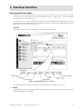
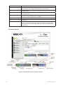
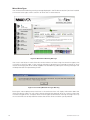
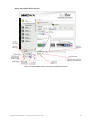
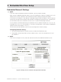
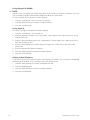
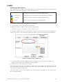
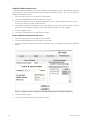
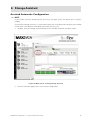
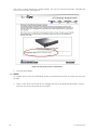
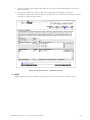
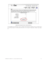
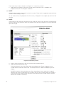
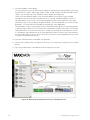
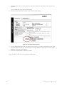
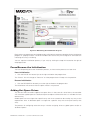
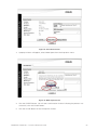
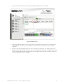
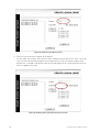
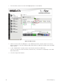
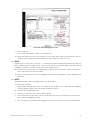
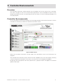
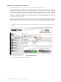
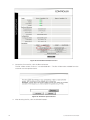
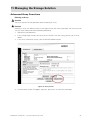
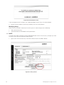
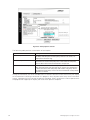
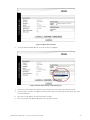
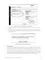
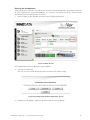
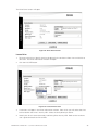
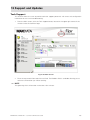
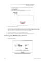
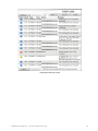
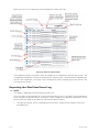
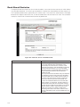
Figure 85. Main Screen
3. Locate the Expand section of the window (lower half), and follow the sequenced steps
beginning at “Step 1” where you will choose a free space region to be used for the expansion.
Figure 86. Logical Drive Information Screen
MAXDATA SR1202 M1 – StorView® RAID User Guide
97
4. In the “Add Capacity” box, enter the amount of the selected region to expand the logical drive.
You may use the entire free region space or a portion of it.
5. Click the EXPAND button.
6. You will be prompted to enter your password to confirm the expansion. Type in your password
and click the GO button.
7. You will receive a screen prompt that the command was successful, click the CLOSE button.
If the command was unsuccessful, review the settings for incorrect parameters and hardware
for operational status.
Deleting a Logical Drive
! Caution
You must stop all host I/O operations prior to deleting an array.
Deleting a logical drive is an option that allows the user to remove an existing logical drive that is no
longer needed or desired. If the logical drive was previously used be sure to make a backup of any
data on the logical drive. After deleting the logical drive, SAN LUN Mapping (if used) and the operating
system will need to be modified due to the missing drive.
1. Stop all host I/O operations.
2. From the Main screen in the Logical Drives section, click on a <logical_drive_name> that you
wish to delete.
Figure 87. Main Screen
The Logical Drive Information window will open.
3. In the Logical Drive section, click the DELETE button.
98
Managing the Storage Solution
Figure 88. Logical Drive Information Screen
4. You will be prompted to enter your password to confirm the deletion. Type in your password
and click the GO button.
5. You will receive a screen prompt that the command was successful, click the CLOSE button.
If the command was unsuccessful, review the settings for incorrect parameters and hardware
for operational status.
MAXDATA SR1202 M1 – StorView® RAID User Guide
99
100
12 Failover, Performance and Additional Functions
How StorView Server Failover Works
The failover feature of the StorView RAID Module must have one of the following setups.
If you are using the host-based version of StorView, two or more host servers must be directly
connected to the SR1202 RAID Storage Solution enclosure and each host must have a copy of StorView
installed with a Global Access license. If you are using the embedded version of StorView, you must
have dual controllers installed (duplex topology) each with embedded StorView installed.
At startup, each StorView server will create a device list of all the attached storage systems. It then
sends the list out on the network as a device list packet. The other StorView servers on the network
will then respond with their device list packets. Since the StorView servers are attached to the same
storage solution, they will have the same or similar devices in their device list packet. The identical
devices in each device list packet will be flagged. After analysis, the StorView server with the lowest
serial number or address will take control of those devices. The other StorView Server will indicate
on its interface that another StorView server is monitoring the storage solution.
During normal operations, the StorView server(s) send “check-in” packets every 10 seconds. If three
consecutive check-in packets for a specific StorView Server are not received, its devices are flagged
and the StorView server attached to that storage solution with the lowest serial number or address
will take control of those devices.
StorView Performance Optimization
There are some parameters that can be adjusted on the host HBA and operating system to increase
the performance of StorView. They are HBA Execution Throttle setting and the operating system‘s
Scatter/Gather registry setting.
Execution Throttle
To improve general I/O performance by allowing more commands on the fibre bus or the SCSI bus,
we recommend changing your host bus adapter’s execution throttle parameter to 256. Refer to your
host HBA documentation for more information.
Scatter/Gather
(Microsoft Windows Only)
To increase general I/O performance by allowing larger data transfers we recommend editing the
“MaximumSGList” parameter in the registry. The recommended hexadecimal value is “ff”. The path
is:
HKEY_LOCAL_MACHINE/System/CurrentControlSet/Services/<name of HBA driver>/
Parameters/Device/
Refer to your Microsoft Windows operating system documentation for more information on editing
the registry and your host HBA adapter documentation.
MAXDATA SR1202 M1 – StorView® RAID User Guide
101
Additional StorView Functions
About
Clicking this button displays the software version information and the type of license installed. When
using the embedded StorView the About window also provides the control button to update the
software.
1. From the Main screen, click the About button, located in the upper right corner of the window
under the StorView logo.
Figure 89. Main Screen
The following screen is displayed. The license type for this installation is indicated below the version
number in parenthesis.
2. Click the CLOSE button on the About window.
Figure 90. About Screen (Host-based StorView)
102
Failover, Performance and Additional Functions
Take Control Monitoring
When multiple host servers are physically attached to the same storage system or the hosts are
attached to a fibre switch in which the switch is physically attached to the storage solution, the installed
StorView server with the lowest serial number or IP address will take control of those devices.
If you wish to take control of the storage solution from another StorView server, click the “Take
Control” link from the Main screen message displayed on that StorView server.
Figure 91. Take Control - Monitoring Screen
After clicking the “Take Control” link on the Main screen, StorView will perform a scan and reload
the configuration for this system. The StorView Server which previously had control will now display
the message that the selected storage solution is being monitored by another StorView server.
You would also see this condition if this StorView server failed to send the required three consecutive
check-in packets and it fails over to another StorView server attached to the same storage system.
Once the problem is resolved on this host StorView Server, you can take back control again with
that StorView server.
MAXDATA SR1202 M1 – StorView® RAID User Guide
103
Rescan
This Rescan function will force a search to re-discover storage solutions in order to refresh the display
and update status information. From the Main screen, click the RESCAN button located on the far left
side of the screen. After a few moments the Main screen is re-displayed with updated information.
Figure 92. Main Screen in Rescan Mode
104
Failover, Performance and Additional Functions
13 Support and Updates
Tech Support
This feature allows the user to provide technical support personnel with event and configuration
information to assist with troubleshooting.
1. From the Main screen, click the Tech Support button, located in the upper right corner of the
window under the StorView logo.
Figure 93. Main Screen
2. Enter the requested information for each field. The Problem field is scrollable allowing you to
review the information you will be sending.

NOTE
The gathering of this information make take a few minutes.
MAXDATA SR1202 M1 – StorView® RAID User Guide
105
Figure 94. Tech Support Screen
3. Click the DOWNLOAD button.
You will receive a screen prompt to save the file on your local disk. Enter a name for the file
and click Save. The software will create a file with your user data, a capture of the event log
files, and a capture of all configuration information. Technical support representatives will be
able to work with this information to assist with solving your problem.
4. Click the CLOSE button on the Technical Support window.
5. When requested by a technical support representative, E-mail the saved file.
Updating Embedded StorView Software
To update the Embedded StorView software:
1. Click the About button.
Figure 95. About Screen (Embedded StorView)
106
Support and Updates
! Caution
Ensure there is uninterrupted power during the update.
2. Click the UPDATE button.
3. Type the name of the firmware file or click the Browse button and locate the file. The file name
will be similar to storview-3.04.T014-XXX-nb-en.bin.
Figure 96. About Update Screen (Embedded StorView)
4. Enter your login password and click the UPLOAD button.
Once the update is complete, StorView Server will automatically restart. This process will not
affect I/O activity.
MAXDATA SR1202 M1 – StorView® RAID User Guide
107
108
14 Event Logs
Overview
StorView has the ability to manage the events generated by the controller, SES processor’s or SAF-TE
processes. StorView also has its own unique events that are related to the StorView server component
of the software. Events can be used to assist with troubleshooting, monitoring components, and
determining the status of hardware components, logical drives and arrays. The following event types
are logged:
•
Drive and Array
•
Controller
•
Network communication (applicable to the host-based version only)
•
Temperature and Voltage
•
Fibre Loop and Bus (Drive and Host)
•
Enclosure components
•
StorView server (applicable to the host-based version only)
There are two event logs maintained: one set of log entries the controller maintains and one set
StorView maintains. There are some differences and limitations between the controller set of event
logs and StorView’s set of event logs. The differences include the type of events logged and in some
cases the ease of interpretation. StorView event logs provide a more user friendly language approach
to describing the event.
The controller’s maximum event log size is 4096 entries with the oldest events being overwritten as
the log reaches the size limit. Some repetitive events are appended to previous events, so entries
are not used up unnecessarily. The controller logs are managed by clicking the Controller icon and
accessing the Operation tab. From there you can export the controller logs to an external file or clear
the log entries.
Enclosure event monitoring can be disabled which reduces the polling that StorView performs thereby
increasing the performance that may be necessary in certain applications. This is accomplished by
deselecting the Enclosure Support option in the Advanced Settings window. Disabling this option
will stop enclosure component monitoring, which can be noted on the Main screen by the dimming
of the enclosure rear view graphics and a notation above the graphic stating “Enclosure Information
Not Available” see ”Controller Environmentals” beginning on page 71.
StorView’s event log will maintain the controller’s compilation of events and the software’s specific
events. The controller’s compilation of events include Controller Events (those unique to the RAID
Controller), Drive Events and Host Events, and if the Enclosure Support option is enabled, enclosure
component events.

NOTE
If the “Enclosure Support” option is disabled, E-mail notifications established for those enclosure
events will not occur.
The StorView server will also perform a synchronization of its event log to the controller log when the
StorView server starts. Since the controller(s) can continue to operate when StorView Server is shut
down, the StorView log would have missing events during this down period. The event synchronization
feature of StorView will append the log with the controller events that occurred while the StorView
server was shutdown.
MAXDATA SR1202 M1 – StorView® RAID User Guide
109
The time stamp for each event in the StorView log is the exact time the event was received by StorView,
and can be slightly off for the actual time it occurred in the controller log. After synchronization, events
that occurred while the StorView server was down are marked with an additional string in the event
description which displays the actual time stamp that event occurred. The string will be in the form
of an asterisk followed by the time and date in parenthesis. At the bottom of the Event Log window
you will find the footnote “* Indicates event occurred while Server module was down”. This indicates
that those events with this extra time stamp in the description are the results of a synchronization
and displays the exact time the event actually occurred.
StorView’s event log has a maximum size limited only by the available disk space, therefore the log
events in StorView will require regular maintenance to ensure the list is manageable and doesn’t
fill to disk capacity. You can export the log files to a comma delimited file prior to clearing them for
later use.
Accessing and Navigating the StorView Event Log
To access the Event Logs, click on the LOGS button located under the focused StorView server icon
on the Main screen.
Figure 97. Main Screen
110
Event Logs
Figure 98. Event Log Screen
MAXDATA SR1202 M1 – StorView® RAID User Guide
111
Below you will find an explanation of the components of the event log.
Figure 99. Event Log Description
The embedded version of StorView does not support some components of Event Log window. The
unsupported components include the Log # column, Log # window, Jump To button, Export button,
and the Clear Log button. Clear log is now handled by the clear controller log function found in the
Environmentals section.
Exporting the StorView Event Log
 NOTE
This option is applicable to the host-based version only.
The event logs can be exported to a comma delimited file for use in third-party software products
when using the host-based version of StorView. Some web browsers provide more options for the
format of the file. Refer to your browser software for specific details.
1. To export the log file, click the LOGS button on the Main screen for the storage system you
are logged into.
112
Event Logs
Figure 100. Main Screen
2. Click the EXPORT button in the Event Logs window.
Figure 101. Event Log Screen
The following are examples of some web browser file export options, your browser may be slightly
different.
•
If you are using Internet Explorer as your web browser, you will see the following screen.
Choose to save the file or open it. The saved file format will be a comma delimited format.
MAXDATA SR1202 M1 – StorView® RAID User Guide
113
Figure 102. Example of Export Log Event Options - Internet Explorer
•
If you are using a Mozilla type web browser, you will see the following screen. This product
provides you with a few more options through the “Advanced” button. Click the Advanced
button and select the file format type, creator application, and other options, as desired.
Figure 103. Example of Export Log Event Options - Mozilla
3. Click the CLOSE button on the Event Logs window.
114
Event Logs
Clearing the StorView Event Log
You can clear the event log from this window when using the host-based version of StorView.
1. To clear the log file, click the LOGS button on the Main screen for the storage system you are
logged into.
Figure 104. Main Screen
2. Click the CLEAR button in the Event Logs window.
This will purge the event logs maintained by StorView for the logged in storage system’s RAID
Controller. This will not clear the log of events maintained by the RAID Controller itself.
Figure 105. Event Log Screen
3. Click the CLOSE button on the Event Logs window.
MAXDATA SR1202 M1 – StorView® RAID User Guide
115
Operating System Event Log
StorView is capable of passing all the events to the host operating system event log. Accessing the
operating system event logs will display events generated by StorView. Each event is identified by an
Event ID. In the tables for the events you will see the Event type followed by its ID. The ID is given in
the format of its hexadecimal value and its equivalent decimal value in parenthesis. The hexadecimal
Event number is how the events are displayed in the operating system event log, and the decimal
value is the format the OS event log will use to display the Event ID.
You can double-click the specific event in the operating system log and it will display a window with
a plain english description of the event.
Also, you can use the tables to locate the event ID and determine the possible cause of that event
and suggested actions to take if necessary.
StorView events are placed into the application event logs.
To shutoff OS event logging, edit the following file using a text editor:
<install directory>/db/server.ini
1. Change the field “UseOsEventLog” from “true” to “false”.
UseOsEventLog = true
enables event logs to be sent to the OS Event log, and,
UseOsEventLog = false
disables event logs being sent to the OS Event log.
2. At the Main screen click the Rescan button. After the rescan is complete events will no longer
be sent to the Windows operating system event log.
List of Events
 NOTE
Events in this chapter are categorized then listed in order of their individual Event Type [ID].
Controller Events
The following table provides a brief description of the events which relates to all models of the RAID
Controller and the Configuration. The type [ID] format is: Event type name with its associated ID
expressed in [hexadecimal (decimal (displayed in the OS))].
Controller Events
Messages
Type [ID]
Cause
Action
There was a fatal xxxx.
Error
[0xB01 (2817)]
Internal hardware or
firmware failure.
Replace the controller.
Where xxxx could be:
- Watchdog Error
- ECC Error
- Host Fibre Channel
Interface Error on
Loop <xx>
- Firmware Error
0x<xx>.
Additional Info: 0x<xx>
0x<xx> 0x<xx> 0x<xx>
0x<xx> 0x<xx>
116
Contact technical support.
Fault SDRAM or
damaged internal bus.
Internal hardware.
Memory or bus error
on the indicated
channel.
Event Logs
Controller Events
Messages
Type [ID]
The controller’s internal Error
temperature <aa>C has [0xB03 (2819)]
exceeded the maximum
limit. The controller will
shutdown to prevent
damage.
Cause
Action
Blocked fan.
Check enclosure for sufficient
air flow.
Failing fan.
Check for a failed fan, if found
replace cooling fan module.
Elevated ambient
temperature.
Check the ambient temperature of the environment,
decrease the local ambient
temperature.
Blocked fan.
Check enclosure for sufficient
air flow.
Failing fan.
Check for a failed fan, if found
replace cooling fan module.
Elevated ambient
temperature.
Check the ambient temperature of the environment,
decrease the local ambient
temperature.
The controller’s
internal temperature
<aa>C is approaching
the maximum limit.
You should check the
cooling system for
problems.
Warning
[0xB04 (2820)]
The onboard cache
protection battery
backup unit has failed
or has been disconnected.
Error
[0xB07 (2823)]
Battery failure.
Replace battery in the
controller.
The partner controller
has failed or has been
removed.
Error
[0xB08 (2824)]
Failure or removal of
one controller (partner)
in an Active-Active
configuration.
Re-install the controller.
This controller has not
Error
received a response
[0xB09 (2825)]
from the other (partner)
controller in the allotted
time, and therefore it
has been disabled.
Failure or removal of
one controller (partner)
in an Active-Active
configuration.
Replace the controller.
An error has been
detected on the SAS
domain or with a SAS
device during the
discovery process.
Error
[0xB0F (2831)]
Possible drive or
internal bus error.
Replace drive.
The controller’s <x>
voltage reading measures <aa>V which
exceeds the limit.
Error
[0xB19 (2841)]
Voltage regulator hardware failure.
Replace the controller.
Internal transfer error.
Error
[0xB1A (2842)]
Hardware problem.
Replace the controller.
The discovery process
has completed identifying all SAS devices
on the SAS domain.
Information
[0xB22 (2850)]
Courtesy informational
message.
No action necessary.
Enclosure 5 V or 12 V
problem in the power
supply.
MAXDATA SR1202 M1 – StorView® RAID User Guide
Replace the controller.
Replace the defective power
supply.
117
118
Controller Events
Messages
Type [ID]
Cause
Action
A discovery process
has started to determine all SAS devices
on the SAS domain.
Information
[0xB23 (2851)]
Courtesy informational
message.
No action necessary.
The other (partner)
controller has been
inserted.
Information
[0xB29 (2857)]
Partner controller has
been inserted.
No action necessary.
The other (partner)
controller has passed
its self-test and is now
ready (failback).
Information
[0xB2a (2858)]
Partner controller is
ready to fail back.
No action necessary.
A stripe synchronizaInformation
tion of a RAID 5/50 set
[0xB2C (2860)
has started. This occurs
when a controller fails,
or after a controller is
powered off with RAID
5/50 write commands in
progress.
A controller fails or is
powered off during a
RAID 5/50 write operation.
No action necessary.
A stripe synchronization of a RAID 5/50 set
has completed.
Information
[0xB2D (2861)]
A controller fails or is
powered off during a
RAID 5/50 write operation.
No action necessary.
The configuration has
changed.
Information
[0xB2F (2863)]
A change in the configuration has occurred.
If you are using the Save
Configuration feature, resave
your configuration information
- it no longer matches. Otherwise no action is necessary.
The controller is
flushing the partner’s
mirrored cache to the
drives. There are <xx>
cache entries totalling
<yy> 512-byte blocks.
Information
[0xB35 (2869)]
Failure or removal of
the partner controller.
No action necessary.
The controller has
completed flushing
the partner’s mirrored
cache to the drives.
Information
[0xB36 (2870)]
Completion of mirrored
cache flushing.
No action necessary.
The battery backup
unit attached to the
controller is now functioning correctly.
Information
[0xB42 (2882)]
Battery charging
complete.
No action necessary.
The controller has been
powered off.
Information
[0xB50 (2896)]
Removal of controller
or power.
No action necessary.
The controller has been
powered on.
Information
[0xB51 (2897)]
The controller was
powered on.
No action necessary.
The controller selftest was successfully
completed.
Information
[0xB52 (2898)]
Self-test completion on
startup.
No action necessary.
The controller self-test
has failed.
Error
[0xB53 (2899)]
Self-test failure on
startup.
Replace the controller.
The controller‘s
NVRAM has been reset.
Information
[0xB54 (2900)]
Occurs first time after
production.
No action necessary.
Event Logs
Controller Events
Messages
Type [ID]
Cause
Action
The controller has an
invalid World Wide
Name.
Error
[0xB55 (2901)]
Occurs first time after
production.
Contact technical support.
The Event Log has been Information
cleared.
[0xB56 (2902)]
The user has cleared
the event log.
No action necessary.
The controller has been
reset.
Information
[0xB57 (2903)]
User initiated a
controller reset.
No action necessary.
The controller has been
shut down.
Information
[0xB58 (2904)]
User initiated a
controller shutdown.
No action necessary.
Check for a failed fan, replace
The controller tempera- as needed.
ture was exceeded and
the controller shut itself Check for blocked air flow,
correct as needed.
down.
Check for high ambient
temperature, reduce the environment ambient temperature.
Failover started.
Information
[0xB5C (2908)]
Failure or removal of
the partner controller.
No action necessary.
Failover completed.
Information
[0xB5D (2909)]
Completion of failover
process.
No action necessary.
Failback started.
Information
[0xB5E (2910)]
Partner controller
started failback.
No action necessary.
Failback completed.
Information
[0xB5F (2911)]
Completion of failback
process.
No action necessary.
The controller firmware
has been upgraded to
version <xxxxx>.
Information
[0xB60 (2912)]
User upgraded the
controller firmware.
No action necessary.
The controller battery
backup unit is charging.
Information
[0xB62 (2914)]
Battery charging
started.
No action necessary.
Flushing of the battery
protected cache has
started. There are <xx>
cache entries totalling
<yy> 512-byte blocks.
Information
[0xB63 (2915)]
Failure of power
with writeback cache
present.
No action necessary.
Flushing of the battery
protected cache has
completed.
Information
[0xB64 (2916)]
Completion of cache
flushing.
No action necessary.
The cache data being
preserved by the
controller’s battery was
lost. There were <xx>
cache entries totalling
<yy> 512-byte blocks.
Error
[0xB65 (2917)]
Failure of power for
an extended time
with writeback cache
present..
Check the file system.
MAXDATA SR1202 M1 – StorView® RAID User Guide
119
Controller Events
Messages
Type [ID]
Cause
Action
An SDRAM ECC error
- bit <xx> at address
<xx,xx,xx,xx.xx> has
been detected and
corrected.
Warning
[0xB72 (2930)]
SDRAM error.
If it repeats, replace the
controller.
A configuration parameter has been changed:
<array name> (Array
<array number>) has
been trusted due to
a cancellation of an
initialization.
Information
[0xB74 (2932)]
A user cancelled an
initialization
No action necessary.
Hardware Error
Additional Info: 0x<xx>
0x<xx> 0x<xx> 0x<xx>
Error
[0xB7a (2938)]
The controller will
continue to function,
however the SES
temperature sensing
may not function properly.
Replace the controller.
Drive and Array Events
These events are related to the drives, loops (where applicable) and disk arrays. The type [ID] format is:
Event type name with its associated ID expressed in [hexadecimal (decimal (displayed in the OS))].
120
Drive & Array Event
Messages
Type [ID]
Cause
Action
The drive w/SN (SAS:
w/ WWN) <xxxxxx>
(Slot <nn>, Enclosure <nn>) (<Array
Name> Drive <member
index>) has failed due
to an unrecoverable
error. Sense Data:
<xx>/<xx>/<xx>.
Error
[0xB0A (2826)]
Typically due to a
non-recoverable media
error or hardware error.
Replace the disk drive.
The drive w/SN (SAS:
w/ WWN) <xx xx xx xx
xx xx> (Slot <number>)
(Drive <number>)
has been marked as
failed because it was
removed.
Error
[0xB0B (2827)]
Drive has been
Replace the disk drive.
removed by the user, or
has a serious hardware
error.
Rebuilding has failed
due to an unrecoverable error on the new
drive w/SN (SAS: w/
WWN) <xxxxxx> (Slot
<nn> (Drive <number>)
in the array.
Error
[0xB0C (2828)]
Removal of cables
connecting the enclosures.
Replace the cables.
Typically due to a
non-recoverable media
error, or hardware
error.
Replace with a new
drive and initiate a
rebuild.
Event Logs
Drive & Array Event
Messages
Type [ID]
Cause
Action
Rebuilding has failed
due to an unrecoverable error on the new
drive w/SN (SAS: w/
WWN) <xxxxxx> (Slot
<nn>, Enclosure <nn>)
(<Array Name> Drive
<num>).
Error
[0xB0D (2829)]
Typically due to a
non-recoverable media
error or hardware error.
Backup all data and
restore to a new array.
The drive w/SN (SAS:
w/ WWN) (Slot <nn>,
Enclosure <nn>) (Slot
<number>) (Drive
<number>) has failed
due to a time-out.
Error
[0xB0E (2830)]
Drive error.
Replace the disk drive.
Disabled Enclosure
Error
<xxxxxx> Slot <nn>
[0xB13 (2835)]
due to excessive errors.
Remove the drive in the
This indicates that the
controller has shutidentified slot to reendown the slot due to
able it.
multiple errors from the
drive. This may be due
to a bad drive or MUX
Transition Board.
SATA Multiplexer
switching failure on
Enclosure <xxxxxx>
Slot <nn>.
Error
[0xB13 (2835)]
Replace the disk drive
This indicates that the
or MUX Transition
controller has tried
multiple times to switch Board.
the Multiplexer on a
SATA drive and it has
not been successful.
This may be due to a
bad drive or MUX Transition Board.
Array <name> is in a
critical state.
Error
[0xB1B (2843)]
Drive removal or
failure.
Replace the disk drive
and rebuild the array.
The drive w/SN (SAS:
w/ WWN) <xx xx xx xx
xx xx> (Slot <number>)
returned a bad status
while completing a
command. SCSI Info:
Operation <type>,
Status <type>.
Error
[0xB27 (2855)]
Unknown status
returned by the disk
drive.
Contact technical
support and provide
them with a copy of the
event log.
The drive w/SN (SAS:
w/ WWN) (Slot <nn>,
Enclosure <nn>) timed
out for the SCSI Operation <type>.
Error
[0xB28 (2856)]
Drive hardware error or
bus error.
Check cabling and
ensure the disk drives
are properly seated.
MAXDATA SR1202 M1 – StorView® RAID User Guide
121
Drive & Array Event
Messages
Type [ID]
Cause
Action
A rebuild has started on Information
the drive w/SN (SAS: w/ [0xB30 (2864)]
WWN) <xxxxxx> (Slot
<nn> (Drive <number>).
A rebuild has started.
No action necessary.
A rebuild has
completed on (Array
<Name> Drive
<number>)
Information
[0xB31 (2865)]
A rebuild has
completed.
No action necessary.
A rebuild has restarted on the drive
w/SN (SAS: w/WWN
<xxxxxx> (Slot <nn>
(Drive <number>).
Information
[0xB32 (2866)]
A rebuild has started.
No action necessary.
Array <name> has
started initializing.
Information
[0xB33 (2867)]
Initialization has
started.
No action necessary.
Array <name> has
completed initializing.
Information
[0xB34 (2868)]
Initialization has
completed.
No action necessary.
The controller has
detected a data
underrun from the
drive w/SN (SAS:
w/WWN) (Slot <nn>,
Enclosure <nn>) for the
SCSI Op Code 0x<xx>.
This is caused by the
controller detecting a
bad CRC in a frame,
and usually indicates
a link problem, either
with cabling or an
enclosure.
Error
[0xB3B (2875)]
Bus error.
Check cabling and
ensure that the disk
drive is properly seated
in its slot.
Typically due to a
non-recoverable media
error, hardware error,
or loop (bus) error.
No action necessary.
An unrecoverable drive Error
error has occurred as
[0xB40 (2880)]
a result of a command
being issued. This may
be due to a drive error
in a non-fault tolerant
array, such as RAID 0,
or when the array is
already in a degraded
mode. The controller
will pass the status
from the drive back
tothe host system, to
allow the host recovery
mechanisms to be
used. Details: Host
Loop <x>, Host Loop
ID <y>, Mapped LUN
Requested <z>,Op Code
<zz>, Sense Data <uu>.
122
Event Logs
Drive & Array Event
Messages
Type [ID]
Cause
Action
A RAID 5/50 parity
check has started on
<Array Name>. Type of
parity check = <paritytype>.
Error
[0xB43 (2883)]
Parity check started.
No action necessary.
A RAID 5/50 parity
Error
check has completed on [0xB44 (2884)]
<Array Name>. Type of
parity check = <paritytype>. Error Count =
<zz>.
Parity check completed.
No action necessary.
A RAID 5/50 parity
check has been aborted
on <Array Name>. Type
of parity check = <paritytype>. Error Count =
<zz>
Error
[0xB45 (2885)]
Parity check canceled
by the user.
No action necessary.
A drive w/SN (SAS:
w/WWN) (Slot <nn>,
Enclosure <nn>) has
been inserted.
Information
[0xB61 (2913)]
Drive was inserted.
No action necessary.
The controller has
started updating a
drive’s firmware. Drive
w/SN (SAS: w/WWN)
<xxxxxx> (Slot <nn>
ID:<zz> Firmware
Version:<yy.yy.yyyy).
Information
[0xB66 (2918)]
The controller has
started updating a
drive‘s firmware. Drive
<w/sn or w/wwn>,
Slot <nn>, Enclosure <nn>, Firmware
Version:<xxxx>
No action necessary.
The controller has
Information
finished updating a
[0xB67 (2919)]
drive’s firmware. Drive
SN: (SAS: w/WWN)
<xx xx xx xx xx xx>
ID:<zz> (Slot <number>)
Firmware Version: <yy.
yy.yyyy).
The controller has
finished updating a
drive‘s firmware. Drive
w/SN or WWN <xxx>,
Slot <nn>, Enclosure <nn>, Firmware
Version:<xxxx>.
No action necessary.
MAXDATA SR1202 M1 – StorView® RAID User Guide
123
Drive & Array Event
Messages
Type [ID]
Cause
Action
An array expansion
has started on Array
<name>.
Information
[0xB68 (2920)]
Expansion has started.
No action necessary.
An array expansion has
completed on Array
<name>.
Information
[0xB69 (2921)]
Expansion has
completed.
No action necessary.
An array expansion
has restarted on Array
<name>.
Information
[0xB6A (2922)]
Expansion has
restarted.
No action necessary.
The writeback cache on Warning
Array <name> has been [0xB6F (2927)]
disabled. Reason(s):
<see causes>.
Disabling of writeback
cache for the indicated
reasons:
• The partner
controller has failed.
• The battery is not
charged or present.
• The array has
become critical.
• A “prepare for shutdown” was received
by the controller.
124
• Replace the failed
controller.
• Charge the backup
battery or re-install
the battery.
• Resolve the array
issue and rebuild the
array.
• No action necessary.
The writeback cache on Information
Array <name> has been [0xB70 (2928)]
re-enabled.
Re-enabling of writeback cache.
No action necessary.
Because of a background verify failure,
data blocks at LBA
<yyy> from drive SN:
(SAS: w/WWN) <xx
xx xx xx xx xx> (Slot
<number>) have been
reallocated.
Warning
[0xB71 (2929)]
Data Blocks at LBA
No action necessary.
<yyy> on Drive w/ SN
(SAS: w/ WWN) <xx xx>
(Slot <nn>, Enclosure
<nn>) have been reallocated.
A rebuild was aborted
on (Array <yy> Drive
<ww>).
Information
[0xB73 (2931)]
A rebuild was canceled
by the user.
No action necessary.
Event Logs
Drive & Array Event
Messages
Type [ID]
Cause
Action
(SATA Drives Only)
SATA Drive Error: (Slot
<number>) Information
<description>.
Error
[0xB75 (2933)]
Drive or SATA link
error.
No action necessary.
(SATA Drives Only)
A drive w/ SN (SAS:
w/ WWN) <xx xx>
(Slot <nn>) has been
removed.
Error
[0xB76 (2934)]
A drive w/ WWN <xx
xx> (Slot <nn>, Enclosure <nn>) has been
removed.
No action necessary.
There was a bad block
during a rebuild on
Array <nn>, Drive
<mm>, LBA <xx xx xx
xx xx xx>, Block Count
<xx>.
Error
[0xB78 (2936)]
A bad block was
detected during the
rebuild operation. Data
loss will occur with that
data stripe.
Replace drive after
rebuild. Restore lost
data from a know good
backup.
Controller Port Events
These events are related to the host side Controller Port. The type [ID] format is: Event type name
with its associated ID expressed in [hexadecimal (decimal (displayed in the OS))].
Controller Port Event
Messages
Type [ID]
Cause
Action
Host Loop 0/1 acquired
Loop ID <xx> because
we were not able to get
Loop ID <xx> (as specified in the controller
settings).
Error
[0xB17 (2839)]
[0xB18 (2840)]
Address conflict with
either host adapter
orother device on the
same loop.
Resolve address
conflict.
A LIP has occurred
on Host loop <xx>.
Reason: <type>, The
LIP was repeated <yy>
times.
Information
[0xB24 (2852)]
A LIP was generated so
that a loop port could
acquire a physical
address on an arbitrated loop.
A LIP was generated
by port ID: <xx> so that
the loop would be re
initialized.
A LIP was generated
because of a loop
failure.
A LIP was generated by
port ID: <xx> because
of a loop failure.
No action necessary.
Host Loop <xx> is now
up.
Information
[0xB25 (2853)]
Loop is becoming
ready.
No action necessary.
Host Loop <xx> is
down.
Information
[0xB26 (2854)]
Loop is going down.
Check/replace the cable.
MAXDATA SR1202 M1 – StorView® RAID User Guide
125
126
Controller Port Event
Messages
Type [ID]
Cause
Action
A host has accessed a
Logical Drive <yy> for
the first time, or for the
first time following a
reset or LIP. It accessed
it through Host Loop
<xx> (ID <zz>) with the
SCSI command <check
condition, busy, or task
set full>.
Information
[0xB2E (2862)]
First access by a
particular host after a
LIP or reset.
A host has accessed a
Logical Drive <yy> for
the first time, or for the
first time following a
reset. ID <zz> accessed
it thru Host Channel
<nn> with the SCSI
command 0x<zz>.
No action necessary.
Host Loop <num> has
reported an error status
of 0x<xx> to a particular command.
Error
[0xB37 (2871)]
This may indicate a
loop reset or LIP during
a command, or a loop
failure. Repeat Count =
<count>.
Contact technical
support.
Host Loop <num> has
reported an invalid
status of 0x<xx> to a
particular command.
Error
[0xB38 (2872)]
This indicates a
firmware error in the
host fibre channel chip.
Contact technical
support.
A SAS command was
aborted on the drive w/
WWN <xx xx xx xx xx
xx xx xx> (Slot <num>,
Enclosure <num>)
for the SCSI Op Code
0x<xx>.
Error
[0xB39 (2873)]
Aborted command.
Possible reasons are:
faulty disk drive, faulty
drive slot, faultyenclosure, cable issue, faulty
drive firmware, fault in
SAS expander, excessive noise, or possible
drive interference.
Error
The controller has
generated a LIP on Host [0xB3D (2877)]
Loop <xx>, due to a
loop error.
Controller initiated a
LIP.
No action necessary.
The host system
w/WWN:<xx xx xx xx
xx xx> and Loop ID of
<xx> has logged into
the controller through
Host Loop <xx>. These
events will only be
listed for HBAs with
SAN LUN Mappings.
Host system logs into
the controller.
No action necessary.
Information
[0xB3F (2879)]
Event Logs
Enclosure Events
These events are related to the enclosure components reported by the SES processor or SAF-TE
processes (SCSI). The type [ID] format is: Event type name with its associated ID expressed in
[hexadecimal (decimal (displayed in the OS))].
Enclosure Event
Messages
Type [ID]
Cause
Action
No SES drives were
found which means
no enclosure status
information can be
reported. This could be
due to the SES slot(s)
in the enclosure having
no drives installed or
the drives are malfunctioning. It may also be
due to a drive target
ID conflict. Check the
enclosure(s) drive’s
hard target ID setting.
Error
[0xB59 (2905)]
No drives installed in
slots 1 or 7.
Insert a disk drive in
either or both drive
slots 1 and 7.
Enclosure ID conflict.
Check the enclosure ID
on all enclosure(s).
Enclosure<xx> (w/
WWN:<xx xx xx xx xx
xx>) timed out on SCSI
command.
Error
[0xB79 (2937)]
This error is generated
when a command to
the Enclosure processor timeouts.
Verify if the system has
gone to SES_LEVEL_1.
If it has, verify the
configuration.
Faulty cables, drives
or Drive I/O Interface
Module malfunction
could be the root cause
of this error.
You may occasionally see this error
during drive insertion,
failover/ failback or
drive removal. As long
as the system remains
at SES_LEVEL_3 the
user does not intervene. If this event is
periodically posted in
the event log the user
may have a hard drive
or Disk I/O Interface
Module problem. The
system should be
inspected to isolate
the problem to either
drives or Disk I/O Interface Module.
NOTE: This event is
only valid for daisy
chained systems.
MAXDATA SR1202 M1 – StorView® RAID User Guide
127
Enclosure Event
Messages
Type [ID]
Cause
Action
Power supply <zz> is
OK.
Information
[0xC6B (3179)]
Normal condition
reported.
No action necessary.
Power supply <zz> is in
a critical state.
Warning
[0xC6B (3179)]
The specific power
supply has failed.
Replace the power
supply.
The specific power
supply is powered off.
Ensure that the specific
power supply On/Off
button is in the On
position ( l ).
Power supply <zz> is
not installed.
Error
[0xC6B (3179)]
The power supply was
removed.
Re-insert the power
supply, connect the AC
power cord and power
on the power supply.
Fan <zz> is OK.
Information
[0xC6C (3180)]
Normal condition
reported.
No action necessary.
Fan <zz> is in a critical
state.
Error
[0xC6C (3180)]
A specific fan failure.
Total fan failure.
Replace the cooling fan
module.
Cooling fan module
was removed.
Re-inset the cooling fan
module.
Temperature sensor
<zz> is OK.
Information
[0xC6D (3181)]
Temperature sensors
are reporting normal
temperatures in the
enclosure.
No action required.
Temperature <zz> is
operating outside of
specifications.
Warning
[0xC6D (3181)]
Temperature sensors
are reporting enclosure
temperatures have
reached the threshold
of 50 °C.
Ensure that both
cooling fans are
operating normally.
(Replace if needed.)
If the fans are set
to automatic speed
control, place the
jumper on the Cooling
fan module circuit
board to force the fans
to high speed.
If the environment
ambient temperature
is high, reduce the
ambient temperature. Ensure that the
airflow is not blocked
or restricted on the
enclosure.
128
Event Logs
Enclosure Event
Messages
Type [ID]
Cause
Action
Temperature sensor
Error
<zz> is in a critical state. [0xC6D (3181)]
Temperature sensors
are reporting enclosure
temperatures have
reached the threshold
of 70 °C.
Automatic system
shutdown will begin. In
Active-Active configurations, one controller
will shutdown its
partner and shutdown
the drives, then itself.
Ensure that both
cooling fans are
operating normally.
(Replace if needed.)
If the fans are set
to automatic speed
control, place the
jumper on the Cooling
fan module circuit
board to force the fans
to high speed.
If the environment
ambient temperature
is high, reduce the
ambient temperature.
Ensure that the airflow
is not blocked or
restricted on the enclosure.
Alarm is Off (Muted).
No condition being
reported.
Alarm muted.
No action necessary.
Information
[0xC6E (3182)]
User pressed the Alarm
Mute button on the ops
panel.
Alarm is Intermittent.
Error
[0xC6E (3182)]
A condition caused
the alarm to sound
every two minutes until
muted.
Press the Alarm Mute
button on the ops panel
and isolate the cause of
the alarm.
Alarm is Remind.
Error
[0xC6E (3182)]
A condition that caused
the alarm to sound is
continuing to remind
the user.
Press the Alarm Mute
button on the ops panel
and isolate the cause of
the alarm.
Alarm is On Continuous.
Error
[0xC6E (3182)]
A condition caused the
alarm to sound.
Press the Alarm Mute
button on the ops panel
and isolate the cause of
the alarm.
SES access fault
tolerant: Multiple paths
are available for gathering this enclosure’s
status information.
Information
[0xCFD (3325)]
An enclosure is now
SES fault-tolerant.
No action necessary.
SES access not fault
tolerant: If this enclosure’s SES enabled
drive fails then no
information about the
status of this enclosure
will be available.
Warning
[0xCFE (3326)]
An enclosure was
found to have only one
available SES drive.
Press the Alarm Mute
button on the front
panel.
Ensure that both slot
1 and 7 have SES
compatible drives
installed.
Ensure that the SES
drives installed in slots
1 and 7 are operational.
MAXDATA SR1202 M1 – StorView® RAID User Guide
129
StorView Server Events

NOTE
These events are applicable to the host-based version only.
The following table provides a brief description of the events which relate to the StorView server
software component. The type [ID] format is: Event type name with its associated ID expressed in
[hexadecimal (decimal (displayed in the OS))].
130
StorView Server Event
Messages
Type [ID]
Cause
Action
The server has been
started.
Information
[0x101 (257)]
The StorView Server
started successfully.
No action necessary.
The server has been
shut down.
Information
[0x102 (258)]
The host is shutting
No action necessary.
down or a user stopped
the StorView service.
A system rescan has
been initiated.
Information
[0x103 (259)]
The system rescan is
starting note: a shutdown and start up
event will follow.
No action necessary.
The serial number and
key entered are incorrect. Remote features
are temporarily disabled.
Error
[0x104 (260)]
The serial number and
key specified in the
server settings file is
not a correct match.
Open StorView in
a browser from the
local console, click the
Settings button. Reenter the serial number
and key. If you still
have problems, contact
technical support.
All event logs cleared.
Information
[0x105 (261)]
A user cleared the StorView event logs.
No action required.
A user <name> has
updated their password.
Information
[0x106 (262)]
A specific user has
updated their password.
No action required.
A user <name> from
Host: <host name>, IP
Address: <IP_address>
unsuccessfully
attempted to update
their password.
Information
[0x106 (262)]
A specific user tried to
Ensure the user is
change the password
authorized or needs
but verification failed or assistance.
old password failed.
A user <name> has
logged into the Server
from Host: <host
name>, IP Address:
<IP_address>.
Information
[0x106 (263)]
A specific user has
logged into the StorView Server from the
specified host and IP
address location.
No action required.
Event Logs
StorView Server Event
Messages
Type [ID]
Cause
Action
A user <name> has
logged out the Server
from IP address:
<IP_address>.
Information
[0x106 (263)]
A specific user has
logged out of the
StorView Server from
the specified IP address
location. (The host
name was not available.)
No action required.
A user <name> has
logged out the Server
from Host: <host
name>, IP Address:
<IP_address>.
Information
[0x107 (264)]
A specific user has
logged out of the StorView Server from the
specified host and IP
address location.
No action required.
The multicast address
is not configured. No
communication will
take place with other
servers.
Warning
[0x201 (513)]
The setting “MulticastPort” is not setup in the
db/IP.db file. The setting
was removed or the file
became corrupt.
Open the file <StorView
folder>\db\IP.db in a
text editor, and add the
following line: MulticastPort=9191. Save the
file and start StorView
and press the Rescan
button or restart the
StorView service.
Multicast socket creation failure: <reason>
Warning
[0x202 (514)]
StorView could not
setup the necessary
communication paths
to talk to other StorView Servers. The
specific cause will
be specified in the
<reason> appended to
the message.
Change the multicast
port used by StorView.
Note that all StorView
servers must communicate with each other
on the same multicast
port. If the setting is
changed on one, they
must be changed on all
StorView Servers.
Open the file <StorView
folder>\db\IP.db in a
text editor, and change
the following line:
MulticastPort=<port
number>. Save the file
and start StorView and
press the Rescan button
or restart the StorView
service.
MAXDATA SR1202 M1 – StorView® RAID User Guide
131
StorView Server Event
Messages
Type [ID]
Cause
Action
Shared memory used
for the Server and the
GUI to communicate
could not be created
nor located.
Error
[0x301 (769)]
StorView tried to
create/locate the shared
memory used for the
Server and Server CGI
script to communicate.
Quit StorView and all
connections accessing
this StorView Server,
wait 1 minute and
restart them.
A CGI request was initiated from the GUI but
the associated shared
memory could not be
opened.
Error
[0x302 (770)]
The Server script
creates new shared
memory for the Server
to access parameter
passed from the GUI.
This shared memory
could not be found.
Retry request.
Quit StorView and all
connections accessing
this StorView Server,
wait 1 minute and
restart them.
Restart the system.
A CGI request was
initiated from the GUI
but the associated
parameters could not
be located.
Error
[0x303 (771)]
The Server script
creates new parameter
for the Server to access
parameter passed from
the GUI. This parameters could not be found.
Retry request.
Quit StorView and all
connections accessing
this StorView Server,
wait 1 minute and
restart them.
Restart the system.
The Server performed
Error
a CGI request but an
[0x304 (772)]
internal error prevented
the Server from
returning the results.
The request was
performed but the
Server encountered an
error that prevented
completion.
Retry request.
Quit StorView and all
connections accessing
this StorView Server,
wait 1 minute and
restart them.
Restart the system.
The Server performed
Error
a CGI request but the
[0x305 (773)]
shared memory needed
to return the results
could not be created.
The Server completed
the request and
attempted to create
shared memory to send
the results back to the
Server CGI. The attempt
failed.
Retry request.
Quit StorView and all
connections accessing
this StorView Server,
wait 1 minute and
restart them.
Restart the system.
The Server completed
the request but by the
time it was done the
Server CGI gave up.
Retry request.
Quit StorView and all
connections accessing
this StorView Server,
wait 1 minute and
restart them.
Restart the system.
The Server failed to
complete a CGI request
before its allowed time
expired.
132
Error
[0x306 (774)]
Event Logs
StorView Server Event
Messages
Type [ID]
Cause
Action
The Server CGI script
was unable to return
CGI request results to
the GUI.
Error
[0x307 (775)]
The Server passed the
completed request
to the Server CGI
but for some reason
the request wasn’t
completed correctly by
the Server CGI script.
Retry request.
Quit StorView and all
connections accessing
this StorView Server,
wait 1 minute and
restart them.
Restart the system.
Start up is complete.
Information
[0xA01 (2561)]
The controller module
has been loaded by the
StorView Server.
No action necessary.
Several failures
encountered while
trying to communicate with the RAID
controller.
Error
[0xA03 (2563)]
Several commands
Ensure that the paths
have been sent through and hardware are
a known good path but operational.
they have failed.
Successful communication with controller
after several failures.
Information
[0xA04 (2564)]
A known failed path
is now functional and
passed retest.
No action necessary.
Failed Drives Codes
The controller maintains a list of failed drives. Drives are listed in the following format:
Failed Drive:xx SN: yy yy yy yy yy yy
Reason Code
The reason code may be one of the following:
Reason Code
Reason
Action
Drive Timeout
The drive has either timed out
or been removed.
Re-insert the disk drive.
Replace the disk drive.
Command: xx Sense Key: yy Ext
Sense: zz
The drive has failed for the
specified command, with the
indicated SCSI sense key and
extended sense key.
Replace the disk drive.
MAXDATA SR1202 M1 – StorView® RAID User Guide
133
134
15 Statistics
Overview
StorView and the SR1202 RAID Controller will monitor all incoming commands, and calculate various
statistics. The statistics monitored include:
•
Command Count
•
Command Alignment
•
Command Size
•
Read-Ahead Statistics
•
Write Clustering Statistics
•
RAID 5/50 Write Statistics
From the Main screen click the Logical Stats button in the Tool Bar.
The controller maintains individual access statistics for individual logical drives or all logical drives,
controllers, and individual or all ports. These can be used to help balance the load from the host.
You may also export the statistical data to a comma delimited file for use in third-party software
products.
Access Statistics
These statistics are for both reads and writes, and can be used to tune the operating system for
optimum performance.
Figure 106. Statistics Screen - Access Tab
Every time statistics are viewed, the controller first outputs the time since the statistics were last
reset. However, the statistics can be cleared at any time. This is useful in determining the access
pattern for a particular test or period of time.
MAXDATA SR1202 M1 – StorView® RAID User Guide
135
Statistic
Description
Reads
This is the average number of MBs transferred in the last few
seconds from the logical drives, controllers or ports. This value is
expressed in MB/seconds.
Writes
This is the average number of MBs transferred in the last few
seconds to the logical drives, controllers or ports. This value is
expressed in MB/seconds.
No. of Operations
This is the total number of read and write accesses that have
occurred since these statistics were reset, or the controller was
last powered on.
Bytes Transferred
This is the total number of bytes read and written since these
statistics were reset, or the controller was last powered on.
Command Size - Alignment Statistics
Command size statistics express the percentage of commands whose size is as specified. The
Alignment statistics is the percentage of commands whose address aligned on the specified address
boundary.
Figure 107. Statistics Screen - Command Size/Alignments Tab
136
Statistics
Statistic
Description
Command Size
Expressed in the percentage of commands whose size is
specified for reads and writes. The values are displayed with a
horizontal bar for each value. The lack of a bar displayed for a
specific value indicates it is 0% (or less than 1%).
For example, consider a read or write command from a host
system with Logical Block Address (LBA) 0x0000070, and
access size 0x80, expressed in decimal 128. Using 512 byte
blocks on the disk drives, it can be seen that this is a read of 64
Kbytes, which is the command size.
Alignment
This is the percentage of commands whose address is aligned
on the specified chunk boundary. The alignment of a command
from a host system is determined by the command’s address.
In an optimal system, a write of one chunk of data would reside
exactly within a chunk on one disk. However, if this is not the
case, this write will be split up into two separate writes to two
different data drives. This of course will have a negative effect
on performance. To overcome these problems, the user can,
with more sophisticated operating systems, set the access size
and alignment to an optimal value. These statistics can help the
user to tune the operating system.
How to Use Command Size and
Alignment
To calculate the alignment, we check the LBA for the largest
number of blocks that will evenly divide into it, in powers of
2. So, we can see that in this case, the alignment is 0x10 = 16
blocks. This equates to 8K.
The alignment, in conjunction with the access size, gives an
indication of how many drives are involved in an access. In the
above example, consider a RAID 5/50 array with a chunk size
of 64K. In this case, the above access will actually involve 2
data drives, since it needs to access 8K in the first drive (0x80
– 0x70 = 0x10 blocks = 8K), and the remaining 56K in the next
drive (0x70 blocks = 56K). This is clearly inefficient, and could
be improved by setting the alignment to 64K on the operating
system. If that is not possible, using a larger chunk size can
help, as this reduces the number of accesses that span chunks.
Aligning an access on the same value as the access size will
improve performance, as it will ensure that there are no multichunk accesses for commands that are smaller thana chunk
size.
MAXDATA SR1202 M1 – StorView® RAID User Guide
137
Read-Ahead Statistics
If sequential read commands are sent to the controller, it assumes that the commands which follow
may also be sequential. It can then go and perform a read of the data, before the host requests it.
This improves performance, particularly for smaller reads. The size of the read-ahead is calculated
based on the original command size, so the controller does not read too much data. The controller
maintains statistics for all read-ahead commands performed.
Figure 108. Statistics Screen - Read-Ahead Tab
138
Statistic
Description
Sequential Command Interval
In determining whether to perform a read-ahead
or not, the controller will search back in the
command queue whenever it receives a new
read command that is not satisfied by an existing
read-ahead cache buffer. In a multi threaded
operating system, commands from one thread
may be interspersed with commands from
another thread.
This requires that the controller not just check the
immediately previous command. The controller
will search back for a number of commands, to
see if the new command is exactly sequential
to any one of these previous commands. If it
is, then the controller determines that the data
access pattern is sequential, and so performs a
read-ahead. These statistics record the average
number of commands the controller must search
back for when it finds a sequential command
match, the maximum number, and also the
percentage for each one of these values. These
give an indication of the multi threaded nature of
the host.
Statistics
Statistic
Description
Read-Ahead Command Hit Rate
This is the percentage of read command hits
versus the total number of read commands that
have been issued. This gives an indication of the
sequential nature of the data access pattern from
the host.
Read-Ahead Command Efficiency
This is the percentage of the number of read
command hits versus the projected number of
read-ahead command hits. This is a measure
of the efficiency of the read-ahead algorithm. A
low value means that much of the data that the
controller reads in the read-ahead command is
not actually requested by the host.
Command Cluster Statistics
To increase performance, the controller can cluster sequential write commands together to create
a larger write command. This results in less commands being sent to the disk drives. Additionally,
if sufficient data is clustered by the controller, then it can perform a a full stripe write for RAID5/50
arrays. This significantly improves performance. In cases where the host does not send a sufficient
number of outstanding writes, writeback cache can be used to delay the write to disk, increasing the
likelihood of clustering more data.
Figure 109. Statistics Screen - Command Cluster Tab
MAXDATA SR1202 M1 – StorView® RAID User Guide
139
140
Statistic
Description
Write Cluster Rate
This is the percentage of the number of write
commands that are part of a cluster versus the
total number of write commands that have been
issued. This gives an indication of the sequential
nature of the data access pattern from the host,
and of the performance of the writeback cache.
RAID 5/50 Full Stripe Write Rate
This is the percentage of the amount of data that
is written as a full stripe write versus the total
amount of data written. This gives an indication of the sequential nature of the data access
pattern from the host, and of the performance of
the writeback cache, for RAID 5/50 drive ranks.
Command Cluster Count
When the controller clusters a write command,
it may cluster a large number of them together.
These statistics record the average and maximum
number of commands the controller clusters, and
also the percentage for each one of these values.
Command Cluster Interval
In determining whether to cluster write
commands or not, the controller will search back
in the command queue whenever it receives a
new write command. In a multi threaded operating system, commands from each thread may
be interspersed with commands from another
thread. This requires that the controller not just
check the immediately previous command.
The controller will search back for a number
of commands, to try to determine if the new
command is exactly sequential to any one of
these previous commands. If it is, then the
controller determines that it can cluster these
commands.
These statistics record the average and maximum
number of commands the controller must search
back for when it finds a sequential command
match, and also the percentage for each one of
these values.
Statistics
16 Optimizing RAID 5 Write Performance
Introduction
With a typical RAID 5 implementation, there are a number of steps that are performed when data is
written to the media. Every write from the host system will typically generate two XOR operations
and their associated data transfers, to two drives. If the accesses are sequential, the parity information
will be updated a number of times in succession. However, if the host writes sufficient data to cover a
complete stripe, the parity data does not need to be updated for each write, but it can be recalculated
instead. This operation takes only one XOR operation per host write, compared to two for a standard
RAID 5 write. The number of data transfers necessary are also reduced, increasing the available
bandwidth. This type of write access is termed a “Full Stripe Write.”
The following illustration displays the distribution of data chunks (denoted by Cx) and their associated
parity (denoted by P(y-z)) in a RAID 5 array of five drives. An “array” is defined as a set of drives, on
which data is distributed. An array will have one RAID level. A “chunk” is the amount of contiguous
data stored on one drive before the controller switches over to the next drive. This parameter is
adjustable from 64K to 256K, and should be carefully chosen to match the access sizes of the operating
system. A Stripe is a set of disk chunks in an array with the same address. In the example below,
Stripe 0 consists of C0, C1, C2, and C3 and their associated parity P(0-3).
Figure 110. Distribution of Data and Parity in a RAID 5 with Five Drives
Maximum performance will be achieved when all drives are performing multiple commands in parallel.
To take advantage of a Full Stripe Write, the host has to send enough data to the controller. This
can be accomplished in two ways. First, if the host sends one command with sufficient data to fill
a stripe, then the controller can perform a Full Stripe Write. Alternatively, if the host sends multiple
sequential commands, smaller than a stripe size (typically matching the chunk size), the controller can
internally combine these commands to get the same effect. In the above example, if a 256K chunk
size is used, then the stripe size is 1 MB (4 chunks * 256K). So, for maximum performance, the host
could either send 5 * 1 MB write commands, or 20 * 256K write commands.
The effectiveness of the controller’s ability to perform a Full Stripe Write depends on a number of
parameters:
MAXDATA SR1202 M1 – StorView® RAID User Guide
141
Sequential Access
If the commands sent from the host are not sequential, the controller will not be able to cluster
them together. So, unless each individual access is sufficient to fill a stripe, a Full Stripe Write will
not occur.
Number of Outstanding Commands
For the controller to successfully cluster commands, there has to be a number of write commands sent
simultaneously. Setting the host to send up to 64 commands should prove adequate. Alternatively,
enabling writeback cache will have a similar effect, as the controller can then cluster sequential
commands even if the host only sends a small number of commands at a time.
Access Size
With very small accesses, it is necessary to have a large number of commands to cluster together to
fill up a full stripe. So, the larger the access size the better. It is best to use an access size that will
fill a chunk. Of course, even if a stripe is not filled up, small sequential writes will still benefit from
command clustering.
Access Alignment
The alignment of a command from a host system is determined by the command’s address. In an
optimal system, a write of one chunk of data would reside exactly within a chunk on one disk. However,
if this is not the case, this write will be split up into two separate writes to two different data drives.
This will have a negative effect on performance. To overcome these problems, the user can, with
more sophisticated operating systems, set the access size and alignment to an optimal value.
As can be seen from the figure below, to get the highest performance from this system, it is necessary
to have a number of stripes being written in parallel. As the array expands, with more and more drives,
the number of commands (and amount of sequential data) necessary to do this increases.
Figure 111. Distribution of Data and Parity in a RAID 5 with Eight Drives
In the figure above, we can see that seven chunks of sequential data are necessary to fill a stripe.
To have multiple commands active for all disk drives, this requires more data than for the case with
five drives. As can be seen, this number will increase as the number of drives increases. If a large
number of drives are used, it may get difficult to achieve maximum performance, as it becomes more
difficult to cluster a large number of commands to achieve a Full Stripe Write.
142
Optimizing RAID 5 Write Performance
RAID 5 Sub-Array
The difficulty in realizing the maximum performance possible introduces the concept of a sub-array.
Suppose an array consisted of two RAID 5 sets, see Figure 110 ”Distribution of Data and Parity in a
RAID 5 with Five Drives”. If these are then striped, the resulting array would appear as shown below.
In this case, in order for a Full Stripe Write to be performed, it is still only necessary to cluster four
write commands together, as opposed to the seven necessary as indicated below. The array of drives
appears as two separate sub-arrays, each with it’s own rotating parity.
Figure 112. Distribution of Data and Parity in a RAID 5 with Ten Drives and Two Sub-Arrays
It can be seen that the more sub-arrays used, the more likely it is for a Full Stripe Write to occur, and
hence the higher the performance. It is recommended to use either four or five drives in a sub-array,
for best performance. On the following page the figure shows that even with 15 drives, it is still
possible to perform Full Stripe Writes, by clustering together 4 chunks of data.
Figure 113. Distribution of Data and Parity in a RAID 5 with Fifteen Drives and Three Sub-Arrays
Multiple Drive Failures
In a configuration with multiple sub-arrays, it is possible for the array to sustain multiple drive failures,
provided that there is only one failure in each sub-array.
Faster Rebuild
A rebuild operation must read data and calculate parity from all the remaining drives in the RAID set. If
multiple sub-arrays are used, this means that it is only necessary to read the data from the remaining
drives in the sub-array, not all of the drives in the array. This increases both the rebuild speed and the
speed of access to missing data, which also has to be recreated from the remaining drives.
Summary
In summary, for maximum performance using RAID 5, it is recommended to use four or five drives
in a sub-array. If there are more than five drives in a sub-array, it is better to use a smaller chunk size,
say 64K or 128K, as this will lead to more Full Stripe Writes.
MAXDATA SR1202 M1 – StorView® RAID User Guide
143
144
17 Troubleshooting
Problems You May Encounter
This chapter provides typical solutions for problems you may encounter while using StorView to
control and manage the storage systems. Also refer to the Event chapter, and review the cause and
actions for each event listed.
Symptom
Reason
Solution
Continuous indications
that the partner controller
has failed or is missing.
A partner controller in an
Active-Active configuration has failed or was
removed.
Until the partner controller is replaced,
temporarily enable Single Controller Mode
in the Controller Parameters tab. Be sure
to disable this option when the partner
controller is to be replaced.
If you are operating in a Stand-Alone configuration, enable the Single Controller Mode
setting in the Controller Parameters tab.
Operating in a StandAlone configuration with
Single Controller Mode
not selected.
Password Error
Password not accepted at
log in.
Password was forgotten
or lost.
Password is case sensitive, ensure that the
password is entered correctly.
Contact technical support for the procedures
to recover from a lost or missing password.
Lost communication with
the RAID Controllers.
Service is hung.
Restart the StorView service. Access the
Control Panel and double-click on Services.
Locate the StorView Service and click Stop.
Once the service has stopped, click Start and
retry the connection by clicking the Rescan
button on the StorView Main screen.
On Linux system access the process viewer
and stop the StorView Process. Restart the
process and click the Rescan button on the
StorView Main screen.
Hot spare not automatically starting when drive
failure occurs in a redundant array in which a
global or dedicated hot
spare is defined.
The Auto Rebuild option
is not enabled in the
Controller Parameters.
Hot spare disk drive is too
small to be used for the
drive replacement.
Waiting for a valid
replacement drive to be
inserted.
Open the Controller Information window
(click the Controller icon), place a check mark
in the box by clicking the check box on the
Auto Rebuild parameter.
Ensure that the disk drive defined as a hot
spare is equal to or greater than the size of
the drive members of the arrays.
Auto Rebuild is not selected and no hot spare
drive is assigned, but Auto Hot Spare is
enabled. The array will begin rebuilding once
a valid replacement drive is inserted in the
drive slot of the failed drive.
MAXDATA SR1202 M1 – StorView® RAID User Guide
145
146
Symptom
Reason
Solution
Consistently occurring
time out errors when the
browser window is open.
Host HBA parameter
settings are not configured for best performance optimization.
Access your Host HBA settings and make the
following changes:
Execution Throttle
Improve general I/O performance by allowing
more commands on the fibre bus. Do this by
changing your host bus adapter’s execution
throttle parameter to 256.
Scatter/Gather (Microsoft Windows)
Increase the general I/O performance by
allowing larger data transfers. Do this by
editing the “MaximumSGList” parameter in
the register.
The recommended hexadecimal value is “ff”.
The path is: HKEY_LOCAL_MACHINE/System/
CurrentControlSet/Services/<name of HBA
driver>/Parameters/Device/.
Shared Memory Error is
displayed.
The CGI script manager
may have not released
a segment of shared
memory.
This may occur when heavy I/O is happening
at the same time you are accessing StorView.
If this occurs you will need to stop and then
restart the StorView Server service.
After switching drives
and/or controllers from
one storage solution
enclosure to another, one
of the solutions reports
that the storage solution
is being monitored by
another host.
Multiple Configuration
WWNs being used.
If you have been interchanging configured drives or controllers between storage
solutions you may have a situation where
multiple solutions are now sharing the same
Configuration WWN. This can be corrected
by changing the Configuration WWN value
found in the Controller Parameters on either
of the storage solutions. After making this
change, all participating host systems will
require a reboot, see ”Controller Environmentals” beginning on page 71.
Troubleshooting
Symptom
Reason
Solution
Inadvertently pulled the
incorrect drive from the
enclosure and the array
is dead.
Possible incorrect
drive identification and
removal.
If by mistake you remove a working drive
member instead of the failed drive, this can
cause the array to fail. In most cases you can
simply re-insert that drive that was incorrectly removed and the array will return to
the same state it was in prior to removing the
drive.
For RAID 5/50 arrays, a drive failure will put
the array in a critical state, if a hot spare was
available the array should go into a rebuild
mode. If you inadvertently remove one of the
known good drives that is in the process of
rebuilding, the rebuild operation will stop.
Once you re-insert the incorrectly removed
drive the array will return to the critical state
and the rebuild process will start again. If you
did not have a hot spare assigned, the array
will be in a critical state. If you inadvertently
remove a known good drive instead of the
failed drive the array will change to a failed
array state. Re-inserting that inadvertently
removed drive will put the array back into a
critical state. Replacing the failed drive will
cause the array to begin a rebuild operation
provided that you assign it as a hot spare or,
if the Auto Hot Spare option was enabled the
rebuild will begin automatically as the new
replacement drive is installed.
For RAID 0 arrays, if you inadvertently
remove a known good drive, the array will
become dead. Once you re-insert the incorrectly removed drive the array will return to
its working state.
For RAID 1/10 arrays, if you inadvertently
remove a known good drive, the array will
become failed. Once you re-insert the incorrectly removed drive the array will return to
its previous state. If the array was critical,
you can then replace the known failed drive
with a working drive and assign it as a hot
spare and the array will begin rebuilding.
NOTE: For all arrays removing a drive
as described above will cause all current
processing I/O from the controller to stop.
Any I/O in progress may have been lost or
cause a corrupt file. Be sure to verify all data
stored during this type of incidence to ensure
data reliability.
MAXDATA SR1202 M1 – StorView® RAID User Guide
147
148
Symptom
Reason
Solution
Expanding Array is
displayed as “Critical.”
Known issue and should
be corrected in the next
software release.
During an array expansion, the array remains
in a fault tolerant state. Should a drive failure
occur during the expansion the operation
will continue until it has completed, then if a
hot spare was assigned, a rebuild operation
will begin automatically. If a hot spare is not
assigned, replacing the failed drive with a
known good drive after the expansion will
cause a rebuild to start, assuming you have
the Auto Hot Spare option selected in the
Controller Parameters.
During the rebuild operation the array will be
critical.
The controller’s IDs and/
or Configuration WWN
was changed and now
there is a communication
failure.
When you changed the
controller IDs, a new
nexus is established
which requires the
operating system and
software to establish new
communication paths.
If you are using Microsoft Windows you can
use the StorView “Rescan” feature to relocate the storage solution(s).
StorView displays a
message: “No storage
solution found.”
The host operating
system is not able to see
the storage solution.
Ensure that the Fibre devices appear in your
HBA’s BIOS.
Ensure that you have the latest driver
installed for your HBA.
Probe the SCSI enclosure to ensure that you
see the solution.
Reboot the host and the storage system.
I received the following
message: “Lost communication with server. The
server may be down.”
During heavy host operations and/or data I/O, the
system may become too
busy to complete CGI
requests from the GUI in
the time allocated.
After several updated attempts have failed
you will see this message. At this time you
can try to use the Browsers’ refresh function to reload the StorView GUI. If that is
unsuccessful, you may need to stop and then
restart the StorView Server service. If you
continue to receive that message, close the
browser and wait until I/O traffic has settle
down before opening the StorView GUI back
up. You will still continue to receive email
notifications and Event logging.
During heavy data
The controller’s onboard
I/O, when I try to make a
resources are consumed.
configuration change I get
a failure saying that the
controller is busy
Configuration changes during heavy I/ O are
not recommended. You can either wait until
there is less data traffic or keep re-trying the
command until it is successful.
Enclosure Main screen
image is dimmed or
greyed out.
Access the Controller Information window by
clicking the Controller icon. Verify the option
“Enclosure Support” is checked and click
Apply. Close the window.
Enclosure Support option
has been disabled.
Troubleshooting
Index
A
About Software Version ............................... 102
Access Alignment......................................... 142
Access Size .................................................. 142
Access Statistics .......................................... 135
Accessing SAN LUN Mapping ........................ 63
Accessing the Drive Panel .............................. 94
Advanced Settings.......................................... 75
Alignment ..................................................... 136
Alignment Statistics...................................... 136
Array ............................................................... 43
Array Events ................................................. 120
Array Status Icon ............................................ 20
Audible Alarm Icon ......................................... 16
Automatically Update Controller Firmware..... 73
Auto Rebuild ................................................... 78
Auto Spare ................................................ 55, 78
Auto Update ................................................... 78
B
Back-off Percent ................................. 43, 47, 90
Background Drive Verification ........................ 78
Bytes Transferred ......................................... 136
C
Cache Flush Array........................................... 43
Changing the Password.................................. 32
Check Parity.................................................... 84
Chunk Size .......................................... 43, 45, 90
Clearing the Configuration .............................. 93
Clearing the Event Log ................................. 115
Command Cluster Count .............................. 140
Command Cluster Interval ............................ 140
Command Cluster Statistics ......................... 139
Command Size ............................................. 136
Configuration
Environmental ........................................... 71
Notification ................................................ 94
Restoring ................................................... 91
Saving ........................................................ 59
Saving/Restoring/Clearing Overview ......... 91
Configuration Name........................................ 77
Configuration WWN ....................................... 77
Configuring Additional Monitoring .................. 33
Configuring Array Writeback Cache................ 49
Configuring for E-MAIL ................................... 29
Configuring Network Settings ........................ 25
Connection Host Ports ................................... 79
Controller ...................................................... 125
Controller Environmentals .............................. 71
MAXDATA SR1202 M1 – StorView® RAID User Guide
Controller Event
Battery Failure ......................................... 117
Battery OK ............................................... 118
Cached Data Lost .................................... 125
Cache Disabled ........................................ 119
Cntrl Temp Exceeded .............................. 117
Configuration Changed ............................ 118
Controller Failback Completed ................ 119
Controller Failback Started ...................... 119
Controller Failed ...................................... 117
Controller Failover Completed ................. 119
Controller Failover Started ....................... 119
Controller Failover Upgraded ................... 119
Controller Firmware Upgraded ................ 119
Controller Powered On ............................ 119
Controller Present ................................... 117
Controller Removed ................................ 117
Controller Reset ...................................... 117
Controller Selftest Failed ......................... 118
Controller Selftest Passed ....................... 118
Controller Shutdown ............................... 117
Controller Timeout ................................... 117
Controller Valid ........................................ 119
Event Log Cleared ................................... 119
Fatal Watchdog Error ............................... 116
Flush Cache Completed .......................... 119
Flush Cache Started ................................ 119
Flush Mirrored Cache .............................. 118
Flush Mirrored Cache Started ................. 118
Recovered SDRAM ECC Error ................ 116
Synchronization Completed ..................... 118
Synchronization Started ........................... 118
Voltage Error ............................................ 117
Controller Events .......................................... 116
Controller Icon ................................................ 22
Controller LUN ................................................ 77
Controller Ports............................................... 59
Controller Port Data Rate................................ 79
Controller Port Events .................................. 125
Controller Port ID ............................................ 79
Create SAN LUN Mapping.............................. 65
Creating Arrays ............................................... 43
Creating Logical Drive..................................... 56
D
Data Rate ........................................................ 79
Dedicated Spare ............................................. 54
Delete SAN LUN Mapping.............................. 68
Deleting Addressee ........................................ 30
Deleting an Array ............................................ 81
Deleting an SNMP Server............................... 32
149
Deleting a Logical Drive .................................. 98
DHCP Manager............................................... 25
DHCP Server .................................................. 25
Diagnostic Dump ............................................ 72
Different Node Name ..................................... 77
Disable Writeback Cache................................ 48
Drive Event
Array Critical ............................................ 121
Array Expansion Complete ...................... 124
Array Expansion Restarted ...................... 124
Array Initialization Completed .................. 122
Array Initialization Started ........................ 122
Drive Rebuild Failure ............................... 122
Drive Status ............................................. 121
Drive Task Full ......................................... 121
Drive Timeout .......................................... 121
Drive Timeout Failure .............................. 121
FW Download Complete ......................... 123
New Drive Rebuild Failure ....................... 122
Rebuild Aborted ....................................... 124
Rebuild Complete .................................... 124
Rebuild Restarted .................................... 124
Rebuild Started ........................................ 124
SES Initialized .......................................... 127
Drive Events ................................................. 120
Drive Identify icon........................................... 85
Drive Selection for RAID 5 Arrays .................. 44
Drive Status
Available .................................................... 15
Critical ........................................................ 15
Dedicated Spare ........................................ 15
Empty ........................................................ 15
Failed ......................................................... 15
Hot Spare .................................................. 15
Initializing ................................................... 15
Locate........................................................ 15
Member ..................................................... 15
Member Failed Array ................................. 15
Queued to Initialize .................................... 15
Rebuilding.................................................. 15
Updating Firmware .................................... 15
Drive Status Icon ...................................... 15, 20
Dynamic IP ..................................................... 26
Expanding an Array ......................................... 88
Expanding Logical Drive ................................. 96
Exporting Logs.............................................. 112
E
L
E-MAIL Notification ........................................ 29
Embedded StorView Upgrade ...................... 106
Enclosure Events .......................................... 127
Enclosure Icon ................................................ 17
Enclosure Support .......................................... 78
Enclosure Temperature Icon .......................... 16
Error Status..................................................... 29
Event Logs.................................................... 109
Event Type Icons ............................................ 29
Execution Throttle ........................................ 101
150
F
Failed Drives ................................................. 133
Failover ......................................................... 101
Fan Icon .......................................................... 16
Faster Rebuild............................................... 143
Fault Tolerance ............................................... 77
Firmware
Environmental ........................................... 72
Update ....................................................... 72
Free Space...................................................... 96
G
Gateway ......................................................... 26
Getting a New IP Address .............................. 26
Global Access ..................................... 11, 12, 27
Global Spare ................................................... 51
H
Hardware Environmental ................................ 72
HBA Port Name .............................................. 63
Host Event
Controller LIP ........................................... 125
Host Port Incorrect Address .................... 125
Logged in at ID ........................................ 126
Loop Down .............................................. 125
Loop Up ................................................... 125
Host Ports....................................................... 79
Hot Spare Drives ............................................ 51
I
Identifying Drive Members ............................. 85
Identity............................................................ 76
Initialization Pause/Resume ............................ 51
Initialization Priority ......................................... 78
Initialize ........................................................... 43
Initializing the Array ........................................ 49
Inter-Server Communication........................... 11
License Manager ............................................ 12
Local Access............................................. 12, 27
Logical Drive
Delete ........................................................ 98
Expanding .................................................. 96
Logical Drive Availability ................................. 43
Logical Drive Capacity .................................... 58
Logical Drive Status Icon ................................ 20
LUN Mapping ................................................. 63
LUN Number .................................................. 59
Index
M
Mapping Name ............................................... 63
Mirror Cache ................................................... 48
Missing ........................................................... 15
Mixed Drive Types.......................................... 18
Mixed Drive Warning Message ...................... 18
Modifying Arrays ............................................ 82
Modifying a SAN LUN Mapping ..................... 68
Module Tabs ................................................... 22
Monitoring the Initialization ............................ 48
Multicast ......................................................... 11
N
Navigating the Event Log ............................. 110
Network Settings............................................ 25
New IP Address.............................................. 26
Node Name .................................................... 63
Notification, Tips for Configuration Changes .. 94
O
Operating System Event Log ....................... 116
Operations
Access Statistics ..................................... 135
Environmental ........................................... 72
Overview ........................................................ 11
SAN LUN Mapping Screen ........................ 64
P
Pause Initialization .......................................... 51
Performance Optimization ............................ 101
Port Connection Advanced Settings ............... 79
Port Name ...................................................... 63
Power Supply Icon.......................................... 16
R
RAID 5/50 Full Stripe Write Rate .................. 140
RAID 5 Sub-Array.......................................... 143
RAID 5 Write Performance ........................... 141
RAID Controller Icon ....................................... 16
RAID Levels .................................................... 43
RAID Level 0................................................... 44
RAID Level 1................................................... 44
RAID Level 10................................................. 44
RAID Level 5................................................... 44
RAID Level 50................................................. 44
Read-Ahead Cache ......................................... 47
Read-Ahead Command Efficiency ................ 139
Read-Ahead Command Hit Rate................... 139
Read-Ahead Statistics................................... 138
Read/Write Access ......................................... 63
Reads Statistics ............................................ 136
Read Only Access .......................................... 63
Rebuilding an Array......................................... 86
Rebuild Priority ............................................... 78
MAXDATA SR1202 M1 – StorView® RAID User Guide
Remote Access .............................................. 27
Remote Login ................................................. 12
Remote StorView Servers Icon ...................... 22
Remove an Individually Monitored Server ...... 34
Removing a Spare .......................................... 55
Rescan .......................................................... 104
Reserved Capacity .......................................... 43
Reserved capacity .................................... 47, 90
Restore Button ............................................... 69
Restore Mapping Changes ............................. 70
Restoring the Configuration............................ 91
Resume Initialization....................................... 51
Rewrite Parity ................................................. 84
S
SAN LUN Mapping ......................................... 63
Creating ..................................................... 65
Overview ................................................... 64
Remove ..................................................... 68
Saving the Configuration ................................ 59
Scatter/Gather .............................................. 101
Secondary Mixed Drive Type Warning ........... 18
Secure Mode .................................................. 27
Secure Web Proxy .......................................... 27
Sequential Access ........................................ 142
Sequential Command Interval ...................... 138
Server Event
All event logs cleared .............................. 130
Multicast address is not configured ........ 131
Multicast socket creation failure ............. 131
Serial and key are incorrect ..................... 130
Server has been shutdown ..................... 130
Server has been started .......................... 130
User has logged in ................................... 130
User has logged out ................................ 131
Server Icon is White ....................................... 11
Server is missing ............................................ 11
SES Event
Alarm is ON ............................................. 129
Encl Alarm is Off ..................................... 129
Encl Temp 27C OK .................................. 128
Encl Temp 50C Warning .......................... 128
Encl Temp 70C Critical ............................ 129
Fan Critical ............................................... 128
Fan OK..................................................... 128
Power Supply Critical .............................. 128
Power Supply Not Found ........................ 128
Power Supply OK .................................... 128
SES Events ................................................... 127
Single Controller Mode ................................... 78
SMTP Mail Server........................................... 29
SNMP Traps ................................................... 31
Software Version .......................................... 102
Spare Drives ................................................... 51
Starting StorView............................................ 27
Static IP .......................................................... 26
151
Statistics ....................................................... 135
Status Environmental ..................................... 72
Storage Assistant ........................................... 35
Storage Solution Icon ..................................... 22
StorView Manager Console ............................ 27
StorView Server Events................................ 130
StorView Server Icon ...................................... 21
Stripe .............................................................. 44
Stripe Size....................................................... 44
Sub-array......................................................... 44
T
Take Control Monitoring ............................... 103
Tech Support ................................................ 105
Terminology
Array .......................................................... 43
SAN LUN Mapping .................................... 63
Tool Bar .......................................................... 13
Advanced Settings .................................... 14
Archive Configuration ................................ 14
Create Array .............................................. 14
Create Logical ............................................ 14
SAN Mapping ............................................ 14
Storage Assistant ...................................... 14
Trust Array ...................................................... 89
U
Unassigned Free Space .................................. 96
Update Controller Firmware ........................... 73
Updating Embedded StorView ..................... 106
Upgrading License .......................................... 27
User Icon ........................................................ 22
V
Verify Parity .................................................... 83
W
Warning Status ............................................... 29
Web Server..................................................... 11
Writeback Cache ...................................... 48, 90
Writes Statistics ........................................... 136
Write Cluster Rate ........................................ 140
152
Index