1
To resize thickness, move all items on the front cover to left or right
on the master page.
MC-307
REFERENCE MANUAL
01904601
’00-2-C3-21N
REFERENCE MANUAL
Before using this unit, carefully read the sections entitled: “USING THE UNIT SAFELY” and “IMPORTANT NOTES” (REFERRENCE MANUAL p. 2; p. 8). These sections provide important information concerning the proper operation of the unit. Additionally, in order to feel assured that
you have gained a good grasp of every feature provided by your new unit, REFERRENCE MANUAL should be read in its entirety. The manual should be saved and kept on hand as a convenient reference.
Copyright © 1999 ROLAND CORPORATION
All rights reserved. No part of this publication may be reproduced in any form without the
written permission of ROLAND CORPORATION.
To resize thickness, move all items on the front cover to left or right
on the master page.
U
S
I
The
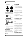
symbol alerts the user to important instructions N
or warnings.The specific meaning of the symbol is G
determined by the design contained within the T
triangle. In the case of the symbol at left, it is used for H
general cautions, warnings, or alerts to danger.
E
The
symbol alerts the user to items that must never
be carried out (are forbidden). The specific thing that U
must not be done is indicated by the design contained N
within the circle. In the case of the symbol at left, it I
T
means that the unit must never be disassembled.
Used for instructions intended to alert
the user to the risk of death or severe
injury should the unit be used
improperly.
Used for instructions intended to alert
the user to the risk of injury or material
damage should the unit be used
improperly.
* Material damage refers
other adverse effects
respect to the home
furnishings, as well
animals or pets.
to damage or
caused with
and all its
to domestic
The ● symbol alerts the user to things that must be S
carried out. The specific thing that must be done is A
indicated by the design contained within the circle. In F
the case of the symbol at left, it means that the power- E
L
cord plug must be unplugged from the outlet.
Y
001
009
• Before using this unit, make sure to read the
instructions below, and the Owner’s Manual.
• Avoid damaging the power cord. Do not bend it
excessively, step on it, place heavy objects on it,
etc. A damaged cord can easily become a shock or
fire hazard. Never use a power cord after it has
been damaged.
..........................................................................................................
..........................................................................................................
002c
• Do not open (or modify in any way) the unit or its
AC adaptor.
..........................................................................................................
003
• Do not attempt to repair the unit, or replace parts
within it (except when this manual provides
specific instructions directing you to do so). Refer
all servicing to your retailer, the nearest Roland
Service Center, or an authorized Roland
distributor, as listed on the "Information" page.
..........................................................................................................
004
• Never use or store the unit in places that are:
• Subject to temperature extremes (e.g., direct
sunlight in an enclosed vehicle, near a heating
duct, on top of heat-generating equipment); or
are
• Damp (e.g., baths, washrooms, on wet floors);
or are
• Humid; or are
• Exposed to rain; or are
• Dusty; or are
• Subject to high levels of vibration.
..........................................................................................................
007
• Make sure you always have the unit placed so it is
level and sure to remain stable. Never place it on
stands that could wobble, or on inclined surfaces.
..........................................................................................................
008c
• Be sure to use only the AC adaptor supplied with
the unit. Also, make sure the line voltage at the
installation matches the input voltage specified on
the AC adaptor’s body. Other AC adaptors may
use a different polarity, or be designed for a
different voltage, so their use could result in
damage, malfunction, or electric shock.
..........................................................................................................
010
• This unit, either alone or in combination with an
amplifier and headphones or speakers, may be
capable of producing sound levels that could
cause permanent hearing loss. Do not operate for
a long period of time at a high volume level, or at
a level that is uncomfortable. If you experience
any hearing loss or ringing in the ears, you should
immediately stop using the unit, and consult an
audiologist.
..........................................................................................................
For the U.K.
IMPORTANT: THE WIRES IN THIS MAINS LEAD ARE COLOURED IN ACCORDANCE WITH THE FOLLOWING CODE.
BLUE:
NEUTRAL
BROWN: LIVE
As the colours of the wires in the mains lead of this apparatus may not correspond with the coloured markings identifying
the terminals in your plug, proceed as follows:
The wire which is coloured BLUE must be connected to the terminal which is marked with the letter N or coloured BLACK.
The wire which is coloured BROWN must be connected to the terminal which is marked with the letter L or coloured RED.
Under no circumstances must either of the above wires be connected to the earth terminal of a three pin plug.
For EU Countries
This product complies with the requirements of European Directive 89/336/EEC.
011
• Do not allow any objects (e.g., flammable material,
coins, pins); or liquids of any kind (water, soft
drinks, etc.) to penetrate the unit.
..........................................................................................................
012b
• Immediately turn the power off, remove the AC
adaptor from the outlet, and request servicing by
your retailer, the nearest Roland Service Center, or
an authorized Roland distributor, as listed on the
"Information" page when:
• The AC adaptor, the power-supply cord, or the
plug has been damaged; or
• Objects have fallen into, or liquid has been
spilled onto the unit; or
• The unit has been exposed to rain (or otherwise
has become wet); or
• The unit does not appear to operate normally or
exhibits a marked change in performance.
..........................................................................................................
For the USA
FEDERAL COMMUNICATIONS COMMISSION
RADIO FREQUENCY INTERFERENCE STATEMENT
This equipment has been tested and found to comply with the limits for a Class B digital device, pursuant to Part 15 of the
FCC Rules. These limits are designed to provide reasonable protection against harmful interference in a residential
installation. This equipment generates, uses, and can radiate radio frequency energy and, if not installed and used in
accordance with the instructions, may cause harmful interference to radio communications. However, there is no guarantee
that interference will not occur in a particular installation. If this equipment does cause harmful interference to radio or
television reception, which can be determined by turning the equipment off and on, the user is encouraged to try to correct the
interference by one or more of the following measures:
– Reorient or relocate the receiving antenna.
– Increase the separation between the equipment and receiver.
– Connect the equipment into an outlet on a circuit different from that to which the receiver is connected.
– Consult the dealer or an experienced radio/TV technician for help.
Unauthorized changes or modification to this system can void the users authority to operate this equipment.
This equipment requires shielded interface cables in order to meet FCC class B Limit.
For Canada
NOTICE
This Class B digital apparatus meets all requirements of the Canadian Interference-Causing Equipment Regulations.
AVIS
Cet appareil numérique de la classe B respecte toutes les exigences du Règlement sur le matériel brouilleur du Canada.
2
07/VDE4B
013
• In households with small children, an adult
should provide supervision until the child is
capable of following all the rules essential for the
safe operation of the unit.
..........................................................................................................
014
• Protect the unit from strong impact.
(Do not drop it!)
..........................................................................................................
015
• Do not force the unit’s power-supply cord to share
an outlet with an unreasonable number of other
devices. Be especially careful when using
extension cords—the total power used by all
devices you have connected to the extension
cord’s outlet must never exceed the power rating
(watts/amperes) for the extension cord. Excessive
loads can cause the insulation on the cord to heat
up and eventually melt through.
..........................................................................................................
016
• Before using the unit in a foreign country, consult
with your retailer, the nearest Roland Service
Center, or an authorized Roland distributor, as
listed on the "Information" page.
..........................................................................................................
101b
• The unit and the AC adaptor should be located so
their location or position does not interfere with
their proper ventilation.
..........................................................................................................
102c
• Always grasp only the plug on the AC adaptor
cord when plugging into, or unplugging from, an
outlet or this unit.
..........................................................................................................
103b
• Whenever the unit is to remain unused for an
extended period of time, disconnect the AC
adaptor.
..........................................................................................................
104
• Try to prevent cords and cables from becoming
entangled. Also, all cords and cables should be
placed so they are out of the reach of children.
..........................................................................................................
106
• Never climb on top of, nor place heavy objects on
the unit.
..........................................................................................................
107c
• Never handle the AC adaptor or its plugs with
wet hands when plugging into, or unplugging
from, an outlet or this unit.
..........................................................................................................
108b
• Before moving the unit, disconnect the AC
adaptor and all cords coming from external
devices.
..........................................................................................................
109b
• Before cleaning the unit, turn off the power and
unplug the AC adaptor from the outlet (Quick
Start p. 2).
..........................................................................................................
110b
• Whenever you suspect the possibility of
lightning in your area, disconnect the AC
adaptor from the outlet.
..........................................................................................................
3
Contents
IMPORTANT NOTES ...............................................................................8
Features of the MC-307 ..........................................................................9
Front and Rear Panels..........................................................................10
Top Panel ................................................................................................................................................... 10
Rear Panel .................................................................................................................................................. 12
Chapter 1 Introducing the MC-307 ......................................................13
Basic structure of the MC-307................................................................................................................. 13
The sequencer section................................................................................................................... 13
The sound generator section ....................................................................................................... 13
The controller section ................................................................................................................... 14
Saving Settings.......................................................................................................................................... 14
Basic Operations Common to General MC-307 Functions................................................................. 14
Changing Values ........................................................................................................................... 14
About the upper part of the display screen .............................................................................. 14
Canceling the Previous Operation (Undo/Redo) .................................................................... 15
Confirming Performance of Rhythm Part (Rhythm Part View)............................................. 15
Metronome Settings...................................................................................................................... 16
Restoring the Factory Settings (FACTORY RESET) ............................................................................ 16
Chapter 2 Basic of Pattern Playback ..................................................17
Basic Functions of Patterns ..................................................................................................................... 17
Playing Back Patterns ................................................................................................................... 17
Changing BPM (Tempo) .............................................................................................................. 18
Muting Parts and Rhythm Tones................................................................................................ 19
Transposing During Playback..................................................................................................... 20
Selecting sounds ....................................................................................................................................... 21
Selecting Patch/Rhythm Set........................................................................................................ 21
Selecting a Patch by Category ..................................................................................................... 21
Changing the settings of each part......................................................................................................... 22
Saving a Pattern ........................................................................................................................................ 23
Chapter 3 Giving Variation to Pattern Playback ................................24
Playing Back with Keyboard Pads......................................................................................................... 24
Shifting the Keyboard Range in One-Octave Steps (Octave Shift) ........................................ 24
Using with Turntable(Turntable Emulation) ....................................................................................... 25
What is the Turntable Emulation? .............................................................................................. 25
Synchronizing the Turntable and the BPM ............................................................................... 25
Use the slider control to synchronize the MC-307’s BPM setting with the turntable. ........ 25
Changing the Tone with the Knobs during Playback (REALTIME MODIFY) ............................... 26
Selecting a Part Subject to Modification .................................................................................... 26
Changing Brightness of the Tone (CUTOFF) ............................................................................ 26
Adding Character to the Sound (RESONANCE) ..................................................................... 27
Applying Cyclic Changes to the Sound (LFO 1) ...................................................................... 27
Changing Other Parameters (Assignable Knobs) .................................................................... 28
Playing Back in Arpeggio (Arpeggiator) .............................................................................................. 31
What is an Arpeggiator? .............................................................................................................. 31
Using the Arpeggiator.................................................................................................................. 31
Selecting the Arpeggio Style........................................................................................................ 31
Making More Detailed Settings .................................................................................................. 32
Saving Arpeggio Settings (Arpeggio Write) ............................................................................. 34
Modifying the Groove of a Pattern (Play Quantize) ........................................................................... 34
Correcting Inaccuracies in Rhythm (Grid Quantize) ............................................................... 34
Adding Swing to the Rhythm (Shuffle Quantize).................................................................... 35
Giving a Groove to the Rhythm (Groove Quantize)................................................................ 35
4
Contents
Calling up Patterns from the Keyboard Pads (Pattern Call).............................................................. 37
Using the Pattern Call function................................................................................................... 37
Registering a Pattern Set .............................................................................................................. 37
Saving a Pattern Set ...................................................................................................................... 38
Playing Back Phrases from the Keyboard Pads (RPS) ........................................................................ 38
What is RPS (Real-time Phrase Sequencing)? ........................................................................... 38
Using the Keyboard Pads to Play Back Patterns ...................................................................... 38
Registering Phrases in Keyboard Pads ...................................................................................... 39
Setting up a Part for RPS.............................................................................................................. 40
Saving the Settings of an RPS Set................................................................................................ 41
Chapter 4 Setting Effects .....................................................................42
Reverb ........................................................................................................................................................ 42
Switching Reverb On/Off............................................................................................................ 42
Adjusting the Reverb Volume for Each Part (Part Reverb Level).......................................... 42
Making Detailed Settings............................................................................................................. 42
Delay (Add echoes to the sound) ........................................................................................................... 44
Switching Delay On/Off.............................................................................................................. 44
Adjusts the Delay Volume for Each Part (Part Delay Level) .................................................. 44
Making Detailed Settings............................................................................................................. 44
Multi-Effects (M-FX) ................................................................................................................................ 46
Switching Multi-Effects On/Off ................................................................................................. 46
Applying Multi-Effects for Each Part (Part M-FX Switch)...................................................... 46
Selecting the Multi-Effects Type ................................................................................................. 47
Defining Parameters in Detail ..................................................................................................... 48
Switching an Effect Function On and Off in Real Time (How to use the GRAB switch) .............. 62
What is the GRAB Switch?........................................................................................................... 62
GRAB switch positions................................................................................................................. 62
How to Use the GRAB Switch to Set an Effect Function......................................................... 62
Chapter 5 Creating Your Own Patterns and Songs ...........................63
Creating Your Own Patterns .................................................................................................................. 63
Recording Your Music as You Play it (Realtime Recording).................................................. 63
Selecting a patch ............................................................................................................................ 64
Recording changes in BPM .......................................................................................................... 67
Recording Data Entered in Sequence ......................................................................................... 68
Individually Editing Performance Data (Micro Edit) ......................................................................... 72
Basic Operation.............................................................................................................................. 72
Musical Data Handled in Microscope Mode ............................................................................ 72
Modifying Performance Data Values......................................................................................... 74
Inserting Musical Data (Insert Event) ........................................................................................ 74
Deleting Musical Data (Delete Event)........................................................................................ 75
Moving Musical Data(Move Event) ........................................................................................... 75
Viewing Desired Performance Data Only (View Filter).......................................................... 75
Editing Patterns (Pattern Edit) ............................................................................................................... 76
Copying a Portion of a Pattern (Copy) ...................................................................................... 76
Erasing Unwanted Data (Erase).................................................................................................. 77
Deleting Unwanted Measures (Delete Measure) ..................................................................... 78
Inserting Blank Measures (Insert Measure) .............................................................................. 79
Transposing the Pitch (Transpose) ............................................................................................. 79
Modifying the Strength of Notes (Change Velocity) ............................................................... 80
Modifying the Note Length (Change Gate Time) .................................................................... 80
Shifting the Timing Slightly (Shift Clock).................................................................................. 81
Thinning Out Unneeded Data (Data Thin) ............................................................................... 82
Creating a Quantized Pattern (Edit Quantize) ......................................................................... 82
Converting the Note Timing of a Pattern (Reclock)................................................................. 83
Saving the Pattern ......................................................................................................................... 83
5
Contents
Playing and Recording Songs................................................................................................................. 84
Playing Back a Song...................................................................................................................... 84
Return to the beginning of the song and play it back.............................................................. 84
Recording a Song .......................................................................................................................... 85
Editing Songs (Song Edit)........................................................................................................................ 86
Clearing All Steps (Clear All Steps)............................................................................................ 86
Deleting Unwanted Steps(Step Delete)...................................................................................... 86
Copying a Song (Song Copy) ...................................................................................................... 86
Saving the Song ............................................................................................................................. 87
Chapter 6 Making Original Patches.....................................................88
Editing Patches ......................................................................................................................................... 88
Changing the Basic Waveform of the Sound (WAVE/FXM) ................................................. 88
Changing the Pitch (PITCH and ENVELOPE) ......................................................................... 89
Changing the Brightness of Sounds (FILTER and ENVELOPE)............................................ 91
Changing the Volume Level and Localization (AMP and ENVELOPE) .............................. 95
Applying Cyclic Changes to the Sound (LFO 1/2) .................................................................. 97
Defining Parameters Affecting the Entire Patch(COMMON/SOLO, PORTA)................... 99
Setting up Controllers (CONTROL MOD, BEND and AFT) ................................................ 102
Saving a Patch.............................................................................................................................. 104
Editing Rhythm Sets .............................................................................................................................. 105
Selecting the Basic Tone of the rhythm (WAVE and KEY) ................................................... 105
Changing the Pitch (PITCH and ENVELOPE) ....................................................................... 106
Changing the Brightness of Sounds (FILTER and ENVELOPE).......................................... 107
Changing the Volume Level and Localization (AMP and ENVELOPE) ............................ 110
Changing the Rate of the Pitch Change (BEND) .................................................................... 111
Adjusting the Effects for Each Rhythm Tone (SEND LEVEL) ............................................. 112
Saving a Rhythm Set................................................................................................................... 113
Copying and Initializing Settings ........................................................................................................ 113
Copying a Patch or Rhythm Set ................................................................................................ 113
Copying a Patch Tone or a Rhythm Tone................................................................................ 113
Initializing a Patch or a Rhythm Tone ..................................................................................... 113
Chapter 7 Environment Configuration and Application with MIDI .114
Saving system settings........................................................................................................................... 114
Configuration (System) ......................................................................................................................... 114
Tuning and Sound Generator Related Settings ...................................................................... 114
Settings Concerning the Display and Controllers .................................................................. 117
Sequencer-Related Settings........................................................................................................ 119
MIDI-Related Settings ................................................................................................................ 123
Arpeggiator Settings................................................................................................................... 127
Settings for RPS Sets ................................................................................................................... 127
Setting for Play Quantize ........................................................................................................... 127
Useful Functions (Utilities) ................................................................................................................... 128
Initializing Patches, Rhythm Tones and Patterns (INITIALIZE) ......................................... 128
Initializing rhythm tones............................................................................................................ 128
Copying Patch Tones and Rhythm Tone (COPY) .................................................................. 128
Saving Data on an External Sequencer (BULK DUMP) ........................................................ 129
Recording the data of all MC-307 data on an external sequencer........................................ 130
Restoring data for all MC-307 data from a MIDI sequencer back to the MC-307.............. 130
Checking the amount of unused internal memory(MEMORY INFORMATION) ............ 130
Restoring the Factory Settings (FACTORY RESET)............................................................... 131
Writing Patches and Patterns in the Memory (WRITE).................................................................... 131
Canceling Execution of Editing and Recording (Undo/Redo)........................................................ 131
Advanced Operation Using MIDI........................................................................................................ 132
About MIDI.................................................................................................................................. 132
Using with an External MIDI Device ....................................................................................... 133
6
Contents
Synchronization with an External MIDI Device..................................................................... 136
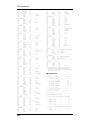
Appendices..........................................................................................139
Troubleshooting..................................................................................140
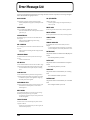
Error Message List..............................................................................142
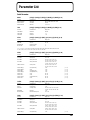
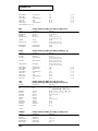
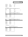
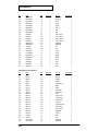
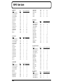
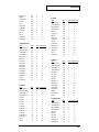
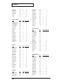
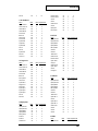
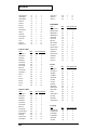
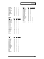
Parameter List .....................................................................................143
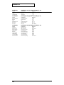
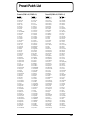
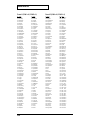
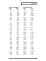
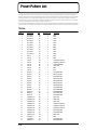
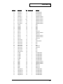
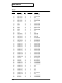
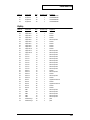
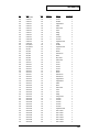
Preset Patch List.................................................................................155
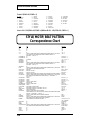
STYLE/MOTIF/BEAT PATTERN Correspondence Chart .................158
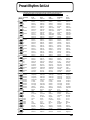
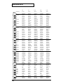
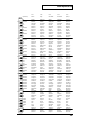
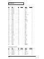
Preset Rhythm Set List.......................................................................159
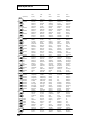
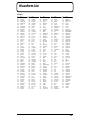
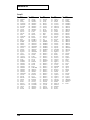
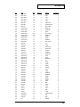
Waveform List .....................................................................................167
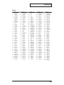
Preset Pattern List ..............................................................................170
RPS Pattern List..................................................................................176
RPS Set List.........................................................................................186
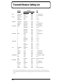
Transmit/Receive Setting List............................................................192
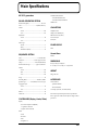
Main Specifications ............................................................................193
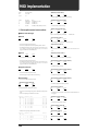
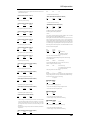
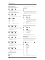
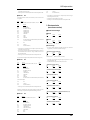
MIDI Implementation...........................................................................194
Index.....................................................................................................210
7
IMPORTANT NOTES
291a
552
In addition to the items listed under “USING THE UNIT
SAFELY” on page 2, please read and observe the
following:
• Unfortunately, it may be impossible to restore the contents
of data that was stored in another MIDI device (e.g., a
sequencer) once it has been lost. Roland Corporation
assumes no liability concerning such loss of data.
Power Supply
553
301
• Do not use this unit on the same power circuit with any
device that will generate line noise (such as an electric
motor or variable lighting system).
302
• The AC adaptor will begin to generate heat after long
hours of consecutive use. This is normal, and is not a
cause for concern.
307
• Before connecting this unit to other devices, turn off the
power to all units. This will help prevent malfunctions
and/or damage to speakers or other devices.
Placement
352
• This device may interfere with radio and television
reception. Do not use this device in the vicinity of such
receivers.
354a
• Do not expose the unit to direct sunlight, place it near
devices that radiate heat, leave it inside an enclosed
vehicle, or otherwise subject it to temperature extremes.
Excessive heat can deform or discolor the unit.
355
• To avoid possible breakdown, do not use the unit in a wet
area, such as an area exposed to rain or other moisture.
Maintenance
401a
• For everyday cleaning wipe the unit with a soft, dry cloth
or one that has been slightly dampened with water. To
remove stubborn dirt, use a cloth impregnated with a
mild, non-abrasive detergent. Afterwards, be sure to wipe
the unit thoroughly with a soft, dry cloth.
402
• Never use benzine, thinners, alcohol or solvents of any
kind, to avoid the possibility of discoloration and/or
deformation.
Additional Precautions
551
• Please be aware that the contents of memory can be
irretrievably lost as a result of a malfunction, or the
improper operation of the unit. To protect yourself against
the risk of loosing important data, we recommend that
you periodically save a backup copy of important data
you have stored in the unit’s memory in another MIDI
device (e.g., a sequencer).
8
• Use a reasonable amount of care when using the unit’s
buttons, sliders, or other controls; and when using its jacks
and connectors. Rough handling can lead to malfunctions.
554
• Never strike or apply strong pressure to the display.
556
• When connecting / disconnecting all cables, grasp the
connector itself—never pull on the cable. This way you
will avoid causing shorts, or damage to the cable’s
internal elements.
558a
• To avoid disturbing your neighbors, try to keep the unit’s
volume at reasonable levels. You may prefer to use
headphones, so you do not need to be concerned about
those around you (especially when it is late at night).
559
• When you need to transport the unit, package it in the box
(including padding) that it came in, if possible. Otherwise,
you will need to use equivalent packaging materials.
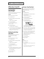
Features of the MC-307
High-performance Synthesizer Sound Generator
A high-performance synthesizer module equivalent to the MC-505 is featured in the sound generator section, the key element for
sound performance. A rich array of parameters, precision filters, and ADSR-style envelopes can be changed with the knobs, the
buttons and the GRAB switch on the panel, allowing you to create sounds as easily as you could on an analog synthesizer. The
MC-307 will also function as an 8-part multitimbral sound module.
Latest Patterns
240types of preset patterns ready to be used and 470types of patterns for RPS materials (one track of data extracted from preset
patterns) are on board. Since the patterns cover a wide range, from techno to reggae, this instrument provides everything you
need for most situations.
Leading-edge Patch Sets
The MC-307’s carefully selected 800 sounds and 40 rhythm sets are just what you need for today’s dance scene, and include great
sounds from vintage instruments such as the TB-303, JUNO, JUPITER and TR-808/909. From the day you purchase the MC-307,
you will be enjoying cutting-edge sounds that cannot be obtained on any other synthesizer.
Original sounds that you create can also be stored in internal memory for immediate access.
Three Digital Effect Units
High-performance DSP (digital signal processing) technology provides you with a wide range of effects. Three multi-effect units
are provided: Reverb adds reverberation, Delay adds echo-like effects, and M-FX (general-purpose multi-effect unit) provides 25
types of effect that have been optimized for dance music.
Isolator and GRAB Switch
Offers a “GRAB switch,” which gained wide acclaim after it appeared on the Roland DJ-2000/DJ-1000 DJ mixer. Used in
conjunction with the powerful isolator, the switch enables real-time on/off operation.
Enhanced Real-time Operation Features
Four “assignable knobs” are provided for assigning desired functions. The user can assign desired parameters to enhance
expressivity for real-time performance.
Use the Arpeggiator to Create Phrases
You can play arpeggios simply by pressing the keyboard pads. By changing the settings, you can perform a variety of different
phrases.
RPS (Real-time Phrase Sequencing) for On-the-spot Addition of Phrases
A phrase can be played back simply by pressing a keyboard pad. This operation can be used to add phrases to a pattern, to give
performance with RPS alone, and for many other purposes.
Function Equivalent to that of a Turntable
A “Turntable Emulation Block” is installed. You can synchronize with other sound modules simply with turntable-like action.
Easy Creation of Original Patterns
“Real-time recording” capability for recording ordinary keyboard performances and a “TR-REC” function for creating patterns
with graphically arranged phrases are incorporated. The TR-REC function is enhanced with a scale editing function, providing a
more convenient means of creating bass lines and melodies.
9
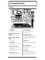
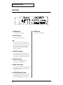
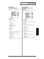
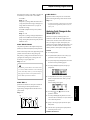
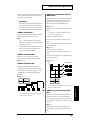
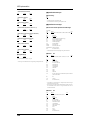
Front and Rear Panels
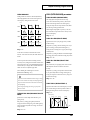
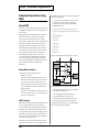
Top Panel
7
10
1
4
2
5
28
8
3
11
12
9
16
29
14
6
15
13
20
18
30
19
17
26
21
27
22
23 24
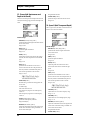
1. VOLUME Knob
Adjusts the overall volume level of the MC-307.
2. MODE Buttons (SONG, PTN and
SYSTEM)
Switch the operating mode of the MC-307.
3. BANK SEL Buttons (PRESET and
USER)
Select patterns and tones.
4. Function Button
Make sure that the setting page for the ARPEGGIO
section is displayed.
5. Knob Assignment Button
Determines which functions should be assigned to
“assignable knobs 1 to 4.”
Instead of the functions listed on the panel, four optional
functions can be assigned.
6. Assignable Knobs 1 to 4
Change such parameters as tones and effects in real time.
10
25
7. LFO 1 Button/Knob
Used to cyclically change musical intervals, the volume
level and the filter.
8. MIDI/SLAVE Indicator
The MIDI indicator will light when MIDI messages are
received from the MIDI IN connector. The Slave
indicator will light when the MC-307 is set to the Slave
setting (P. 119 ).
9. GRAB Switch
This switch can be used for real-time on/off operation of
the reverb, delay and Multi-effect (M-FX) functions. (P.
62 )
10. FILTER Button/Knob
Used for real-time operation of CUTOFF (P. 26 ) and
RESONANCE (P. 27 ).
11. VALUE Dial
Used to set/change the settings on the display. This is
convenient for making large changes in values. (If you
want to make even larger changes in a value, hold down
[INC] or [DEC] button and rotate this dial.)
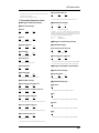
Front and Rear Panels
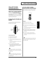
24. HOLD Button
12. EXIT Button
Mainly used to return to the previous screen.
Pressing this button is equivalent to pressing and
holding down a keyboard pad, except you can release
the pad.
13. ENTER Button
Use this to execute an operation.
25. Keyboard Pads
14. INC and DEC Buttons
Used to set/change the displayed settings. Useful for
setting precise values.
15. PART SELECT Button
Press this button to select the part that is to be controlled
in real-time.
26. PAD SELECT Button
(TR REC, ARP, PTN CALL, RPS)
Determines how the keyboard pads are to used.
27. TAP Button
16. PART MUTE Button
Allows you to change the BPM to the timing you’ve used
to tap this button.
Press this button to use the part mute function.
17. RHYTHM MUTE Button
28. PITCH and BPM Buttons
Press this button to use the rhythm mute function.
Used to select a slider and HOLD/PUSH function.
Lighting the PITCH button enables musical intervals to
be changed, while lighting the BPM button enables
playback velocity to be changed. Turning both functions
on implements a function similar to the pitch controller
of the slider and turntable.
18. R and 1 through 7 Buttons
Used to select a part, to mute a part and to mute a
rhythm.
19. RHYTHM PART VIEW Button
29. HOLD and PUSH Buttons
Provides graphic display for confirming the data
configuration of the rhythm part. (P. 15 )
20. SEQUENCER Button (
Normally, these pads are used as keyboard keys, but
they can also be used as buttons to start phrases (RPS: P.
38 ) and for setting the TR-REC timing scale (P. 68 ).
)
Used for various operations including Reset, rewinding,
fast-forwarding, stopping, Playing, and Recording of
patterns and songs.
21. SCALE Button
These emulate the acitions of pushing and holding a
turntable to change its rotational speed.
30. TURNTABLE EMULATION Slider
Normally, this function is equivalent to increasing or
decreasing the speed of the turntable. Used in
conjunction with the PITCH/BPM button, it can be used
for changing solely the pitch or the playback velocity.
Used to select note assignments for the TR-REC mode (P.
68 ).
22. OCT - / + Buttons
This is used for transposing the octave of the keyboard
pad.
23. TRANSPOSE Button
Transposing the sound source.(The rhythm part is not
subject to transposition.)
11
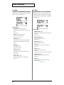
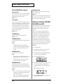
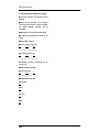
Front and Rear Panels
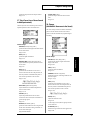
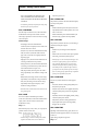
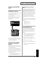
Rear Panel
5
1
2
3
This switch turns the power on/off.
2. DC IN Connector
Connect the included AC adaptor here.
Be sure to use only the AC adaptor supplied with the unit.
Also, make sure the line voltage at the installation matches the
input voltage specified on the AC adaptor’s body. Other AC
adaptors may use a different polarity, or be designed for a
different voltage, so their use could result in damage,
malfunction, or electric shock.
3. MIDI OUT Connector
This transmits MIDI messages from the MC-307 to
external MIDI devices. In addition, if still at the factory
settings, data arriving at MIDI IN is also transmitted.
4. MIDI IN Connector
This connector receives MIDI messages that are
transmitted from external MIDI devices.
5. PEDAL SW Connector
By connecting an optional pedal switch (such as the DP2) to this connector, you can use the pedal to perform
operations on the MC-307.
Provide output of the audio signals. Connect them to
your keyboard amp, audio system, or mixer etc. Use
audio cables (sold separately) to make connections.
12
7
4
1. POWER Switch
6. OUTPUT L(MONO)/R Jacks
6
7. PHONES Jack
Accepts connection of headphones.
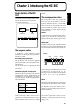
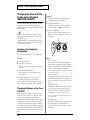
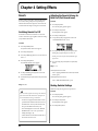
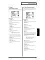
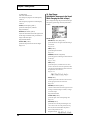
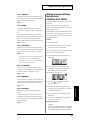
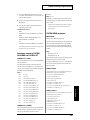
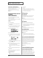
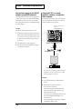
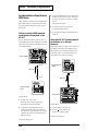
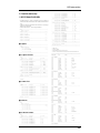
Chapter 1 Introducing the MC-307
This section is an overview of the basic sections of the
MC-307: the sequencer section, sound generator
section, and controller section.
SOUND MODULE
Section
SEQUENCER
Section
PLAY
Keyboard Pad Play
1
2
3
4
5
6
8
9
10
11
12
13
14
The sound generator section
The sound generator is what actually produces the
sound. The sounds are generated in accord with
information arriving from the MC-307’s controllers and
sequencer. Performance data from an external MIDI
device can also play the sound generator. The sound
generator of the MC-307 is able to produce up to 64
notes simultaneously, more than enough for playing
multiple parts at once.
Patches
Recording
7
patterns.
15
16
Controller (Keyboard Pad, Knob)
A patch is analogous to a particular instrument, such as
a piano or guitar. The MC-307 contains 800 preset
patches, and you can enjoy virtually any type of sound
simply by selecting one of these patches.
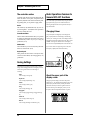
Rhythm Sets
The sequencer section
A sequencer is a device that records musical
performance data, and can play back the performance
data that was recorded.
A rhythm set allows you to play a different instrument
from each note of the keyboard. The instruments will
not sound the pitches of the scale. 40 preset rhythm sets
are provided.
(Example)
SNARE
Recording/playing a performance
The MC-307 comes with 240 previously prepared
patterns (preset patterns). These preset patterns can be
played back easily.
You can also create your own original patterns, either
by modifying preset patterns or by creating a pattern
from scratch.
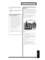
Simultaneous playback of multiple parts
The MC-307 is able to play multiple sounds (patches)
simultaneously. For example, with the following part
configuration, you can simultaneously play drums,
bass, piano and guitar; and the resulting performance
will sound like a band.
Part R
Rhythm (Drum) Set
Part 1
Bass
Part 2
Piano
Part 3
Guitar
1
2
3
KICK
4
5
6
HI-HAT
7
8
9
10
11
CRASH
12
13
14
15
16
TOM
Parts
A part is analogous to an individual musician in a band
or orchestra. There are eight parts, [R], [1]... [7],
allowing you to use seven patches and one rhythm set
to play a total of up to eight performances
simultaneously.
Effects
The MC-307 provides three effect processors that can be
used to apply various tonal effects to a patch or rhythm
set: Reverb (reverberation), Delay (echo-like effects),
and Multi-effects (choose from 25 effects such as
equalizer or compressor). All three effect processors can
be used simultaneously.
Editing performance data
Patch editing
Unlike a cassette tape or MD, a sequencer records a
performance as musical data (not as sound). It’s easy to
edit the performance data to create your own original
The sound of a preset patch or rhythm set can be
modified to your liking. (For details refer to "Patch
editing," p. 92.)
13
Chapter1
Basic structure of the MC307
Chapter 1 Introducing the MC-307
The controller section
Controllers refer collectively to the keyboard pads, the
knobs and sliders on the panel, and pedal switches
(separately sold) that can be connected to the rear panel.
By operating these, you can perform or apply effects.
Knobs
The CUTOFF (P. 26), RESONANCE (P. 27), LFO 1 (P.
27), and assignable 1 - 4 (P. 28)knobs can be operated in
real time to modify the sound.
Turntable emulation
Basic Operations Common to
General MC-307 Functions
You can efficiently operate the MC-307 by using the controls
appropriate for the goal you have in mind. Refer to the
following descriptions of the various operations and try to
keep them in mind.
Changing Values
GRAB switch
Use [VALUE] dial for making major value changes and
[INC] or [DEC] button for incrementing or decrementing
values by one. To change the value, use the display field in a
black frame with characters displayed in white. This is called
“cursor.” To change more than one value on the display,
move the cursor with [CURSOR] buttons to the relevant area.
This switch allows you to turn reverb, delay, and multieffects on/off in real time. (P. 62)
(If you want to mato even larger changes in a value, hold
down [INC] or [DEC] button and rotate this dial.)
These are sliders and buttons that allow you to perform
in real time synchronization with sound sources such as
a turntable. They make it easy for you to enjoy DJ
performance. (P. 25)
Keyboard pads
These perform the same function as a keyboard. They
can also be used for RPS (P. 38) and arpeggiator (P. 31)
performance.
Cursor
Saving Settings
Perform the save procedure to retain the results of setting
changes and recording performances. Turning the power off
without saving results in the loss of the settings or
recordings.
- Patch
refer to Saving a Patch (p. 104).
- Rhythm set
refer to Saving a Rhythm Set (p. 113).
- Pattern
refer to Saving a Pattern (p. 23).
- Song
refer to Saving the Song (p. 87).
- Arpeggiator
refer to Saving Arpeggio Settings (Arpeggio Write) (p.
34).
- Pattern set
refer to Saving a Pattern Set (p. 38).
- RPS set
refer to Saving the Settings of an RPS Set (p. 41).
14
About the upper part of the
display screen
The upper part of the display screen shows the pattern
number (P. 17) / song number, RPS set number (P. 38), patch
number (P. 21), and the currently selected part number.
These items will always be shown, regardless of what is
shown in the lower part of the display, so that you will
always have the most important information at a glance.
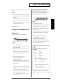
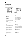
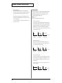
Canceling the Previous Operation
(Undo/Redo)
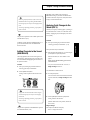
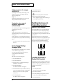
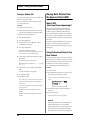
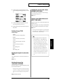
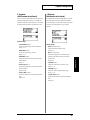
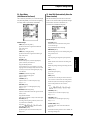
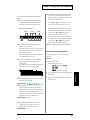
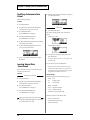
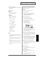
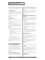
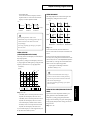
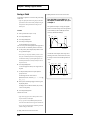
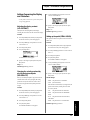
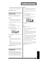
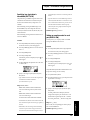
Confirming Performance of
Rhythm Part (Rhythm Part View)
For songs and patterns, editing (track and microscopic
editing) and recording operations can be canceled.
For the rhythm part (PART R), a graphical display is
available for confirming what kind of performances are
recorded for the respective patterns. This operation is useful
when you want to check how the rhythm part performance is
configured.
Before Recording/Editing
Procedure
Recording/Editing
REDO
UNDO
1. Press [RHYTHM PART VIEW] button.
2. From the part buttons, [BD]–[OTHERS], select and press
the button associated with the rhythm tone that you
want to confirm.
After Recording/Editing
Either one of the rhythm tones appeared at the left or
right section of the display can be selected for viewing.
For example, the rhythm buttons [BD] and [CYM] button
can be switched by pressing the appropriate button.
Procedure
1. Press [SYSTEM] button.
2. Press [F4 (UNDO)] button.
3. Press [
] or [
] button to select the location you
want to be displayed.
The display shows groups of numerals, such as "1-1-00,"
indicating "Measure-Beat-Clock."
The item subject to UNDO is displayed. For example,
“UNDO MICROSCOPE” appears for undoing
microscopic editing.
3. Press [F4 (EXEC)] button to execute this function, or
press [EXIT] button to cancel.
Upon completion, a “COMPLETED!” message appears on
the display and the screen returns to the initial screen that
appears upon power up.
.
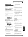
The following marks are displayed.
: Data exists
- : Data does not exist
* While this screen is displayed, pressing [SCALE] button
changes the unit of one “
.”
UNDO can be executed for Pattern (track editing,
microscope editing and recording) or Song (editing,
recording).
REDO is an operation of restoring the initial contents
before executing UNDO. Repeating the steps above
after executing UNDO executes REDO
* For operations (a) and (c) below, press [
] or [
]
button to switch the display between the first half and the
second half of one measure.
- a. Displays half the length of one measure in sixteenth
triplet.
- b. Displays the length of one measure in eighth triplet.
- c. Displays half of the length of one measure in thirtysecond notes.
- d. Displays the length of one measure in sixteenth notes.
* This function cannot be used if the System setting “RHY
VIEW” (P. 122) is set to “MUTE CTRL.”Switch the setting
to “NORMAL” before you use this.
15
Chapter1
Chapter 1 Introducing the MC-307
Chapter 1 Introducing the MC-307
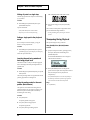
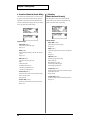
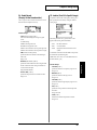
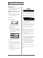
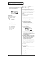
Metronome Settings
The metronome can be set to automatic on/off according to
the operating mode of the MC-307.
Procedure (Pattern/Song play screen)
Restoring the Factory
Settings (FACTORY RESET)
This operation can restore the settings of the MC-307 to their
factory settings.
1. Press [PTN] (or [SONG]) button.
2. Press [F4 (BPM)] button.
3. Press [CURSOR (up/down)] buttons to move the cursor
over to “METRO NOME.”
When Factory Reset is executed, the data in the MC-307’s
memory is lost. If there is any data in the MC-307 that you
do not want to delete, use the Bulk Dump operation (P. 129)
to save the data to an external MIDI sequencer or similar
device.
Procedure
4. Set up the mode using [VALUE] button dial or [INC/
DEC] buttons.
1. Press [SYSTEM] button.
The menu screen for system set-up appears.
Procedure (Realtime Recording screen)
2. Press [F2 (UTIL)] button.
1. Press [PTN] button.
3. Press [CURSOR (down)] button.
Go to the screen where “FACTORY RESET” appears.
2. Press [REC] button.
3. Press [F2 (REALTIME)] button.
4. Press [PLAY] button.
Realtime Recording starts.
4. Press [F1 (FACT)] button.
The “FACTORY RESET” screen appears and an “ARE
YOU SURE?” message appears.
5. Press [F4 (BPM)] button.
6. [CURSOR (Up/Down)] button to move cursor over to
“METRONOME.“
7. Set up the mode using [VALUE] button dial or [INC/
DEC] buttons.
Available Settings
- OFF:
The metronome does not play, regardless
of the operation of the MC-307.
- ON:
The metronome plays, regardless of the
operation of the MC-307.
- REC ONLY: The metronome plays only during
recording.
- PLAY&REC: Sounds during playback and recording.
* You can also set the volume of the metronome. For the
procedure, refer to Setting up the volume level of the
metronome (METRONOME LEVEL) (p. 119).
16
5. Press [F4 (EXEC)] button to execute factory reset.
After 6 minutes, factory reset is completed and the
“COMPLETED!” message appears.
After a short while, the screen displayed immediately after
startup appears.
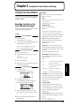
Chapter 2
Basic of Pattern Playback
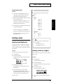
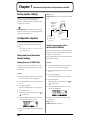
Basic Functions of Patterns
Playing back patterns continuously
A pattern consists of 1 to 32 measures of play that include
patches and rhythm sets of up to 8 parts.
Selecting the next pattern while a pattern is being played
back, the new pattern is played back when playback of the
current one is completed.
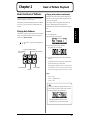
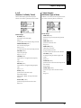
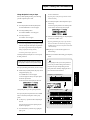
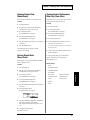
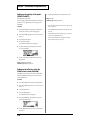
Playing Back Patterns
The MC-307 is a sequencer that plays back patterns and adds
changes to the playback method. This type of sequencer is
referred to as a pattern sequencer.
*
This technique is used to keep playing back patterns in
sequence. The BPM (tempo) of the performance is
determined by the tempo of the first Pattern that is played
back.
Procedure
Chapter2
The MC-307 is provided with 240 preset patterns. In addition
to these, an area for up to 200 user-created patterns is also
available.
1. Press [PTN] button.
The pattern playback screen appears.
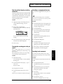
buttons can also be used while playback
is in progress.
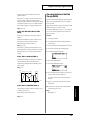
2. Press [PLAY] button to begin playback.
The pattern play screen appears.
Return to the previous measure.
Go to the beginning
of the song.
Advance to the next measure.
3. Select the pattern using [VALUE] dial or [INC/DEC]
STOP
PLAY
REC
buttons.
After playback of the current pattern is completed, the
pattern selected in step 3 is played back.
Stop the Sequencer.
Use in recording.
Play Back.
* Immediately before playback of a pattern is completed, [PTN]
button blinking. At this term, the pattern cannot be changed;
the MC-307 is already prepared to proceed to the next pattern.
Range:
- P: 001 – P: 240
- P: 241 – P: 710(RPS Pattern)
- U: 001 – U: 200
You can press [PTN] button that appears in the screen
in "Step 2" of the procedure to switch to the screen that
also shows the name of the selected Pattern.
* Pressing [PTN] button when this screen is
displayed returns you to the screen in Step2.
17
Chapter 2 Basic of Pattern Playback
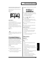
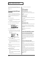
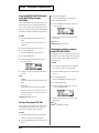
Playing Back at the Tempo Set for the
Pattern
Viewing the number of measures in a
pattern
In order to play back patterns at the BPM (tempo) set up for
the respective patterns, select a pattern while no pattern is
being played back, then start playback.This secures playback
at the optimal BPM for the pattern.
The measure number and the rhythm can be indicated on the
display. This operation is useful when the BPM (tempo)
cannot be easily measured due to muting of the rhythm part.
Procedure
1. Press [STOP] button to stop playback.
2. Press [PTN] button.
This appears the screen for playing patterns.
Procedure
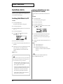
1. Press [PTN] button.
2. Press [F4 (BPM)] button.
A window appears and displays the measure number
(MEAS) and the beat (BEAT) currently played back.
3. Use [VALUE] dial or [INC/DEC] button to select the
pattern.
Pattern length Current Measure - Beat
4. Press [PLAY] button.
Playback begins.
Press [EXIT] or [F4] button to close the window.
Range:
- P: 001 – P: 240
- P: 241 – P: 710 (RPS Pattern)
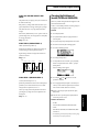
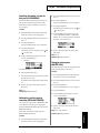
Changing BPM (Tempo)
- U: 001 – U: 200
On-the spot playback of the next
pattern
It is also possible to play back the next pattern upon pressing
of the button.This operation is useful for searching for a
target pattern by checking patterns one by one.
Procedure
1. Press [PTN] button.
The pattern playback screen appears.
2. Press [PLAY] button to begin playback.
The pattern is played back.
With some Preset Patterns, raising the BPM too high can cause
sluggish performance.
Changing BPM with the Value Dial
A BPM value is specified for playback. This operation is
useful when you have a BPM value for playback in mind.
Procedure
1. Press [PTN] button.
2. Press [F4 (BPM)] button.
A window appears.
3. Press [CURSOR (left/right)] buttons.
The pattern immediately before or after the current one
is played back right away.
* When playback is stopped, you can use the [CURSOR
(left, right)] buttons to select patterns by categories such
as "techno," "house," and so on.
Range:
- P: 001 – P: 240
- P: 241 – P: 710(RPS Pattern)
3. Use [CURSOR (up/down)] buttons to move the cursor
over to the BPM value.
4. Change the BPM value using [VALUE] dial or [INC/
DEC] buttons.
After completing the settings, press [EXIT] or [F4] button to
close the window.
Range: 20.0–240.0
- U: 001 – U: 200
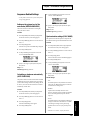
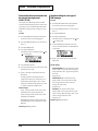
Changing BPM with the TAP button
You can establish the BPM by tapping on the TAP button at
the desired rhythm. This allows you to set the tempo using
18
Chapter 2 Basic of Pattern Playback
your own sense of rhythm, even if you don’t know the settings
value.
Procedure
1. Press [TAP] button more than three times to change the
tempo a quarter note at a time to obtain the BPM desired
for playback.
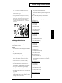
Muting rhythm tones individually
Musical instruments used in Part R can be muted
individually. These instruments are muted by instrument
type such as bass drum (BD) and snare drum (SD).
* You can also set the BPM by pressing the TAP button using
eighth-note timing. refer to Changing the resolution of the tap
tempo (TAP RESOLUTION) (p. 122).
Range BPM: 20.0–240.0
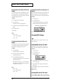
Muting Parts and Rhythm Tones
Muting parts
Part R and Parts 1 to 7 can be muted individually.
Procedure
1. Press [RHYTHM MUTE] button.
The [R], [1] to [7] PAD buttons change to the Rhythm
Tone Mute function buttons ([BD]-[OTHERS]).
2. Press the part button, [BD]–[OTHERS], for the rhythm
group to be muted.
The sound from that rhythm tone is muted. Press the
button for the muted part again to cancel the mute.
The part button indicator operates as follows:
- Lit: The Rhythm group can be played back.
- Blinking: The Rhythm group is muted.
Procedure
- Extinguished: No performance is recorded in the
Rhythm group. (The indicator will come on after some
data are entered through recording.)
1. Press [PART MUTE] button.
The part buttons, [R], [1] to [7], function as buttons for
the part muting function.
2. Press the part button, [R], [1] to [7], for the part to be
muted.
The tone of that part is muted. Press the button for the
muted part again to cancel the muting function.
The part button indicator operates as follows:
- Lit: The part can be played back.
- Blinking: The part is muted.
- Extinguished: No performance is recorded in the part.
(The indicator will come on after some data are entered
through recording.)
* Part 1 of Preset Pattern P: 001 to P: 240 does not contain any
performance data. This part is useful for performances using
the keyboard pads or the arpeggiator. (P. 31)(P. 38)
* Preset Pattern for RPS P: 241 to P: 710 contains performance
only in Part 1 (or Part R) to be used for RPS.
* You can change the mute status of each part, and save the
setting in a user pattern. (P. 23)
Association of rhythm groups and buttons for
muting them
- BD:
Bass Drum
- SD:
Snare Drum
- HH:
Hi-Hat
- CLP:
Hand Claps
- CYM:
Cymbal
- TOM/PERC: TomTom/Percussion
- HIT:
hit such as a one-shot SFX sound.
- OTHERS:
Other instruments
* If you would like to know which tone is muted by
muting a particular rhythm group?
... refer to Preset Rhythm Set List (p. 159).
* Using the part muting function to mute Part R mute all
rhythm tones regardless of the settings for respective rhythm
tones.
19
Chapter2
This timing is adopted as the BPM used for playback.
Chapter 2 Basic of Pattern Playback
Muting all parts in a single step
"MR" is displayed in the center of the screen.
The following operation mutes all parts associated with [R],
[1] to [7] buttons.
Procedure
1. While holding down [PART MUTE] button, press
[RHYTHM MUTE] button.
4. Select a pattern using [VALUE] dial or [INC/DEC]
buttons.
All parts will be muted.
After a while, the selected pattern is played back with the
previous PART MUTE setting maintained.
* Then [PART MUTE] button’s indicator blinks.
* Repeat step 1 to restore the state before muting.
Setting a single part to the playback
mode
Just one of the parts associated with [R], [1] to [7] part
buttons is set to the playback mode.
Procedure
1. While holding down [PART MUTE] button, press the
part button, [R], [1] to [7], for the part you want to play.
All the other parts will be muted.
Inverting the part being muted and
that being played back
* Pressing the blinking [PLAY] button again cancels this
function.
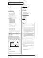
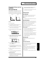
Transposing During Playback
This operation changes the key by semitones.
Using [VALUE] dial or [INC/DEC] buttons
Procedure
1. Specify the transposition value by operating [VALUE]
dial or [INC/DEC] buttons while holding down
[TRANSPOSE] button.
The “REALTIME TRANSPOSE” screen is displayed
while this button is held down.
This function is used to set the part currently being played
back to the muting mode and the part being muted to the
playback mode.
Procedure
1. While holding down [PART MUTE] button, press [PART
SELECT] button.
This sets the part being muted to the playback mode and the
part being played back to the muting mode.
Using the muting mode for the next
pattern (Mute Remain)
This operation is used to maintain the muting mode for
playing back the next part. It is useful, for example, to play
back the next pattern with the rhythm track muted by
maintaining the current setting.
Procedure
1. Press [PTN] button.
The pattern playback screen appears.
2. Press [PLAY] button to begin playback.
The pattern is played back.
3. Press [PLAY] button again during playback.
20
2. Release [TRANSPOSE] button when the playback
position reaches the point where transposition is desired.
Then, the subsequent section is played back in
transposed keys.
* Press [TRANSPOSE] button to reset the transposed keys to
the initial keys. The indicator of the button goes off and the
state is switched to the mode without transposition.
Range:
-12– +12 (semitones)
Chapter 2 Basic of Pattern Playback
Procedure
1. 1. Press [OCT +] button (lighting the button) when
setting a positive value; press [OCT -] button when
setting a negative value (lighting the button).
2. Hold down [TRANSPOSE] button and press a keyboard
pad to set the transpose value.
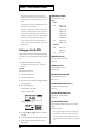
5. Press [PRESET] button or [USER] button to make
selection between preset patches and user patches.
6. Select a patch using [VALUE] dial or [INC/DEC]
buttons.
Range:
- Patches
Preset
P: A001 - 128
P: B001 - 128
P: C001 - 128
P: D001 - 128
P: E001 - 128
P: F001 - 128
P: G001 - 032
User
U: A001 - 128
U: B001 - 128
The transpose value can be set in a range of -12– +12
semitones, above and below the C4 key (which will be
keyboard pad [2] if Octave Shift is “0”).
3. The transposition will be applied from the moment that
you press the keyboard pad.
To return to the original key, press [TRANSPOSE]
button once again to make the button indicator go dark.
- “Shifting the Keyboard Range in One-Octave Steps
(Octave Shift)” (P. 24)
Chapter2
Using the keyboard pads
- Rhythm sets
Preset
P: A01 - 26
P: B01 - 14
User
U 01 - 20
Selecting sounds
Selecting Patch/Rhythm Set
The MC-307’s Patterns are composed of up to eight Parts,
and different Patches (Part1 - 7: Patches, Part R = Rhythm
set)can be selected for each Part. To change tones, first select
the desired Part.
Procedure
First, select the part in which a patch is to be selected.
If you would like to know what patches/rhythm
sets are available?
- “Preset Patch List” (P. 155)
- “Preset Rhythm Set List” (P. 159)
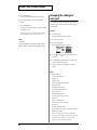
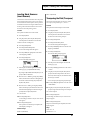
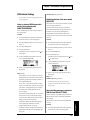
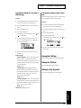
Selecting a Patch by Category
1. Press [PTN] button.
Patches can be selected by category such as piano, organ, etc.
(Part 1 - 7 only.)
2. Press [F1 (PACH)] button.
The names of the patches in the currently selected part
are displayed.
Procedure
3. Press [PART SELECT] button.
The part buttons, [R], [1] to [7], function as the part
selection buttons.
4. Press the part button, [R], [1] to [7], for the part
containing the patch that you want to transpose.
The part associated with the button pressed is selected
and its name appears in the top right-hand corner.
Next select a patch.
1. Press [PTN] button.
The pattern playback screen appears.
2. Press [F1 (PACH)] button.
The names of the patches in the currently selected part
are displayed.
3. Press [F2 (CATG)] button.
The category selection screen appears.
4. Select a category using [VALUE] dial or [INC/DEC]
buttons.
21
Chapter 2 Basic of Pattern Playback
5. Press [ENTER] button.
The screen contains patches in the selected category.
6. Select a patch using [VALUE] dial or [INC/DEC]
buttons.
7. Press [ENTER] button.
The patch is selected and the display returns to the initial
patch display screen.
* Selection by category is also possible for real-time recording,
for which the above procedure can be applied. (P. 64)
Changing the settings of
each part
You can modify the settings of each part to change how the
pattern will sound. The six items listed in “Setting ranges”
can be adjusted.
Procedure
1. Press [PTN] button.
The pattern playback display will appear.
Range:
2. Press [F2 (STUP)] button.
CATEGORY:
PIANO, KEYS&ORGAN, GUITAR, BASS, ORCHESTRAL,
BRASS, SYNTH, PAD, ETHNIC, RHYTHM&SFX, USER
3. Press [F1 (PART)] button.
The “PART MIXER” display will appear.
4. Use [F1 ( )] or [F2 (
wish to set.
)] buttons to select the item you
5. Use [CURSOR (left/right)] buttons to select the part for
which you wish to make settings.
6. Use [VALUE] dial or [INC/DEC] buttons to make
settings.
Range:
- LEVEL (Part Level)
Set the volume of the part.
Range: 0–127
- PAN (Part Pan)
Set the left/right position of the part.
Range: L64–0–63R
- KEY SHIFT (Part Key Shift)
Set the transposition of the part.
Range: -48–0– +48
- REVERB (Part Reverb Level)
Set the amount of reverb for the part.
Range: 0–127
- DELAY (Part Delay Level)
Set the amount of delay for the part.
Range: 0–127
- M-FX SW (Part M-FX Switch)
Specify whether or not the part will use the multi-effect.
Range: OFF, ON, RHY
* RHY can be selected only for a rhythm set. When RHY is
selected, M-FX will be applied according to the setting for each
individual tone of the rhythm set. If you select ON for a
rhythm part, M-FX will be applied to all tones.
22
Chapter 2 Basic of Pattern Playback
- SEQ OUT (Sequencer Output Assign)
Specify the output destination from the sequencer to the
sound source.
Range:
- INT: Output to the internal sound generator.
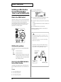
Saving a Pattern
When you have made the settings for patches used for a
pattern and the mute mode, save the pattern as a user
pattern.
- EXT: Output to the MIDI OUT connector.
When these settings windows are displayed, each of the
settings can be made using the assignable knobs 1-4.
- When Part R, 1, 2, or 3 is selected:
The assignable knobs 1-4 are used for setting Parts R and
1-3, respectively.
- When Part 4, 5, 6, or 7 is selected:
The assignable knobs 1-4 are used for setting Parts 4-7,
respectively.
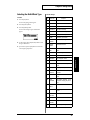
On the MC-307, the following parameters are saved
for each pattern.
These parameters are collectively referred to as the
“Setup parameters.”
- Standard Tempo (P. 18)
- Patch/Rhythm Set Number * (P. 21)
- LEVEL * (P. 22)
- PAN * (P. 22)
- KEY SHIFT* (P. 22)
- REVERB LEVEL * (P. 22)
- DELAY LEVEL * (P. 22)
- M-FX SWITCH * (P. 22)
- SEQ OUT * (P. 23)
- REVERB settings (P. 42)
- DELAY settings (P. 44)
- M-FX settings (P. 46)
- Part Mute status * (P. 19)
- Rhythm Mute status (P. 19)
The “*” indicates parameters that are set
independently for each part.
Unless saved, the data for any recorded or edited Pattern is lost
when the power is turned off.
Chapter2
- BOTH: Output to both of the above simultaneously.
Procedure
Stop operation if the pattern is being played back or
recorded.
1. Press [SYSTEM] button.
2. Press [F3 (WR)] button.
3. Press [F3 (PTN)] button.
The screen for specifying the pattern to be saved and the
destination pattern appears.
The pattern is saved under the pattern number selected
here. Care is needed when selecting an appropriate
pattern number since the pattern previously saved under
that name is deleted.
4. Press [F4 (WR)] button.
The pattern naming screen appears.
5. Use [VALUE]dial or [INC/DEC]button to specify
characters.
The following characters are available.
space, A–Z, a–z, 0–9,! “ # $ % & ‘ ( ) * +, - . / : ; < = > ? @
[\]^_`{|}
6. After characters have been specified, press [F4 (OK)]
button.An “ARE YOU SURE?” message appears.
7. Press [F4 (EXEC)] button.
SAVE operation is executed.
* In step 5 above, upper-case or lower-case versions of the
selected characters can be specified by pressing [CURSOR
(up/down)] buttons.
* In step 5, [F1] and [F2] buttons can be conveniently used for
editing the name.
- [F1 (INS)]: Press to insert a character at the cursor
position.
- [F2 (DEL)]: Press to delete the character at the cursor
position.
23
Chapter 3
Giving Variation to Pattern Playback
Playing Back with Keyboard
Pads
Using the Keyboard Pads to Play Sounds
1. Make sure that all the [ARP], [PTN CALL], [RPS] and
[TR-REC] button indicators are dark.
If any button is lit, press the button to light it up.
Shifting the Keyboard Range in
One-Octave Steps (Octave Shift)
Octave Shift is a function that shifts the pitch of the keyboard
pads in one-octave units. This lets you shift the range of the
keyboard pads to the most convenient range for playing.
Normally when you press keyboard 2, the pitch of the C4
note (middle C) will sound. (Both OCT buttons dark.)
Procedure
1. Use [OCT - /+] button to shift the pitch range.
The keyboard will be shifted in the - / + direction, and
the button indicator will light.
2. Press [PART SELECT] button.
3. Press the PART button [R], [1] to [7] for the part that you
wish to play.
1
2
3
4
5
6
7
8
9
10
11
12
13
14
15
16
* The part selected by the PART SELECT button and PART
buttons is referred to as the Current Part.
4. Play the keyboard pads, and you will hear the sound of
that part.
<HOLD function>
Pressing the [HOLD] button to turn on the indicator
enables the sound to be played back even after the
Keyboard pad is released. Pressing the [HOLD] button
again turns the indicator and the function off.
<Checking the parts that are sounding>
When the [PART SELECT] button indicator is lit, the part
indicators [R], [1] to [7] will light at the timing at which
keyboard pads are played or notes of the pattern are
played. This is convenient when you wish to know which
parts are currently sounding.
* When connecting an external MIDI keyboard, refer to
"Using an external MIDI keyboard in place of the
keyboard pads (REMOTE KEYBOARD) "(p. 123).
24
Range: -4 – +4
* When operating the [OCT] button, pressing and holding it
down for a moment displays the amount of current octave
shift.
* Each time you press [OCT +] button, the range will be shifted
upward by one octave. Each time you press [OCT -] button.
* Pressing the [OCT -] button and [OCT +] buttons at the same
time resets octave shift to “0.”
Chapter 3 Giving Variation to Pattern
Using with Turntable
(Turntable Emulation)
Operation similar to touching a
turntable ([HOLD] and [PUSH] buttons)
Synchronizing the Start with the Turntable Using the BPM
button, synchronize the starting point with the turntable.
What is the Turntable Emulation?
The MC-307 has a TURNTABLE EMULATION slider, just
like a record player, for BPM adjustment, and TURNTABLE
HOLD/PUSH buttons that make effects just like holding and
turning the turntable possible.They enable start and tempo
alignment during turntable playback.
Use the slider control to synchronize the MC-307’s
BPM setting with the turntable.
Procedure
1. Begin playback with the turntable.
2. Begin playback of the MC-307’s Pattern (p. 5).
3. Confirm that both the [PITCH/BPM] buttons above the
slider are lit.
If not lit, press one or both buttons to turn the function,
lighting the button or buttons.
Decreases
the BPM
Increases
the BPM
Set-up/operating procedure
4. If the MC-307’s playback is running slower than the
turntable’s, press the [PUSH] button to speed up the
performance.
5. If the MC-307’s playback is running ahead of the
turntable’s, press the [HOLD] button to hold back the
performance.
1. Begin playback with the turntable.
2. Begin playback with the MC-307.
3. Confirm that both the [PITCH/BPM] buttons above the
slider are lit.
If not lit, press one or both buttons to turn the functions,
lighting one or both buttons.
In Step 3, if only the [PITCH] button is pressed and lit, then
only the pitch is changed. If only [BPM] is pressed and lit,
only the BPM changes.
4. Move the TURNTABLE EMULATION slider.
Moving the slider up reduces the BPM (slows down the
tempo). Moving the slider down increases the BPM
(speeds up the tempo).
At the center point of the slider a “click” (where the slider
catches slightly) can be felt. At this position, the BPM will be
at its original value.
In Step 3, if only the [PITCH] button is pressed and lit, then
only the pitch is changed. If only [BPM] is pressed and lit,
only the BPM changes.
25
Chapter3
Synchronizing the Turntable and
the BPM
Chapter 3 Giving Variation to Pattern
Changing the Tone with the
Knobs during Playback
(REALTIME MODIFY)
The tone can be modified during playback using the knobs
on the MC-307 panel. In addition, the items subject to
modification can be changed using the four assignable knobs
below the display.
Procedure
1. Select a part, following the procedure described in
“Selecting a part subject to modification.”
2. Press the [FILTER] button.
The filter type can be selected each time this button is
pressed. For details, see “Range“ described later.
3. Turn the [CUTOFF] knob.
- Movement of the controls does not result in any effect
unless the controls are adjusted beyond a certain range (a
value of about 2 or 3).
- If Realtime Modify is used to change the parameters in a
Pattern, then the Pattern reverts to its initial settings when
you switch to the next Pattern.
Turning it clockwise produces a brilliant tone, while
turning it counterclockwise produces a smoother, more
rounded tone.
3
Selecting a Part Subject to
Modification
Select a part from Part R and Parts 1 to 7 for modifying the
tone.
Procedure
1. Press the [PTN] button.
2. Press the [F1 (PACH)] button.
The name of the patch in the currently selected part is
displayed.
3. Press the [PART SELECT] button.
The part buttons, [R], [1] to [7], function as the part
selection buttons.
4. Press the part button, [R], [1] to [7], for the part
containing the patch that you want to modify.
The part number of the selected part is displayed in the
“PART” field in the top right-hand corner of the display.
Changing Brightness of the Tone
(CUTOFF)
Sound consists of a large number of overtones at various
frequencies. By using a filter, you can cause only a specific
range of overtones to be passed or attenuated, thus
modifying the brightness. The FILTER section lets you make
settings that affect the brightness of the sound in this way.
Turning the CUTOFF knob clockwise produces a brilliant
tone, while turning it counterclockwise produces a smoother,
more rounded tone. Another effective use of this knob is to
operate it during playback to add changes according to the
BPM.
26
2
Range:
- LPF (Low Pass Filter)
Rotating the knob clockwise will cause the sound to
become brighter, approaching the original waveform.
Rotating it counterclockwise will cut more of the high
frequency overtones, making the sound darker.
* For some waveforms, you may not be able to hear any sound if
you lower the value too far.
- BPF (Band Pass Filter)
Rotating the knob clockwise will raise the frequency area
that is heard. Rotating the knob counterclockwise will
cause only a progressively lower frequency area to be
heard.
- HPF (High Pass Filter)
When the knob is turned clockwise, the low frequency
range will be cut more greatly, making the sound
sharper. As the knob is rotated toward the left, the
original sound of the waveform will be heard.
* For some waveforms, you may hear no sound if this value is
closed to maximum.
- PKG (Peaking Filter)
When the knob is turned clockwise, the frequency area
that is emphasized will rise. Rotating the knob
counterclockwise will lower the frequency area that is
emphasized.
Chapter 3 Giving Variation to Pattern
When using the filter functions, be careful not to raise the
RESONANCE value too high. Setting the RESONANCE
value too high may cause output at excessively high volume
levels.
Some settings may damage your hearing, or your speakers.
Please use caution.
This procedure is equivalent to the CUTOFF operation of the
Patch Edit function. (P. 92)
Depending on the CUTOFF setting, increasing the
RESONANCE setting may not achieve the intended effect.
To make the effect more conspicuous, modify the CUTOFF
setting as well and confirm the effect.
Applying Cyclic Changes to the
Sound (LFO 1)
The LFO (Low Frequency Oscillator) applies cyclic change to
the sound. Effects such as vibrato, wow and tremolo can be
added by changing the pitch, cutoff frequency and volume
level cyclically.
Procedure
Adding Character to the Sound
(RESONANCE)
This setting emphasizes the overtones in the region of the
cutoff frequency, adding character to the sound. This is one
of the tone modifications highlighting the characteristics of
the synthesizer sounds.
Procedure
1. Select a part, following the procedure described in
“Selecting a part subject to modification.”
2. Turn the [RESONANCE] knob.
Turning it clockwise produces adds resonance to the
tone.
Using the MC-307 with the Resonance Limiter settings (P.
115) value too high may cause output at excessively high
volume levels.
Some settings may damage your hearing, or your speakers.
Please use caution.
1. Select a part, following the procedure described in
“Selecting a part subject to modification.” (P. 26)
Select a parameter subject to modification.
2. With the [LFO1] button held down, set a value using the
[VALUE] dial or the [INC/DEC] buttons.
While it is held down, the “LFO 1 ASSIGN” screen
appears.
When you have finished making your selection,
release the button.
* Select from PITCH, FILTER and AMP. For details, see
Range of settings described later.
Next, determine the oscillation of LFO.
3. Press the [LFO1] button.
An LFO waveform can be selected each time this button
is pressed. For details, see Range of settings described
later.
4. Turn the [DEPTH] knob under the [LFO1] button.
Turning it enhances the LFO effect.
(When the knob is in the center position, the LFO will
have no effect.)
Range of settings:
This procedure is equivalent to the RESONANCE operation
of the Patch Edit function. (P. 93)
Items subject to modification with [LFO]
- PITCH:
Changes note intervals.
27
Chapter3
In addition, operating the knob with RESONANCE set to a
greater value enhances the effect of the RESONANCE
function on the tone.
Chapter 3 Giving Variation to Pattern
- FILTER: Changes the cutoff frequency of the filter.
Procedure
- AMP:
1. Press the button to the left of the assignable knobs.
Changes the amplifier volume level.
LFO Waveform
- TRI (triangle): The sound will be modulated
continuously. This is a frequently-used waveform, and is
suited for effects such as vibrato.
Each time you press it, “>” in the figure comes on in
sequence. Thus, you can select from the functions listed
on the display. The available functions are listed in the
column with “>” on.
2. Operate the knobs while playing back sounds.
- SIN (sine wave): The sound will be modulated smoothly.
- SAW (sawtooth wave): When the sound reaches the
upper value, it will return to the original position and
begin rising again.
- RND (random): This setting causes the sound to change
unpredictably, and is suitable for creating sound effects.
- S&H (sample & hold): This setting causes the sound to
change unpredictably, and is suitable for creating sound
effects.
- SQR (square wave): The sound will be modulated as if it
were being switched between two positions.
This procedure is equivalent to the [LFO1] operation of the
Patch Edit function. With the Patch Edit function, the two
waveforms shown below can also be selected.
Parameters for the respective knobs
- REVERB TIME:
Changes reverb time. refer to "Adjusting the length of
reverberation (TIME) "(p. 43).
- REVERB HF:
Changes the tone of the reverb. refer to "Adjusting the
tone of the reverberation (HF DAMP) "(p. 43).
- DELAY TIME:
Changes delay time.
refer to "Adjusting the delay interval (TIME) "(p. 45).
- DELAY FB: Changes delay feedback.
refer to "Adjusting the number of repeats (FEEDBACK)
"(p. 45).
- TRP (trapezoid wave): The sound will be modulated as if
it were being switched between two positions. The curve
at the transitions differs from square wave.
- M-FX CTRL 1:
Changes the CTRL1 parameter of Multi-effect. refer to
"Defining Parameters in Detail "(p. 48).
- CHS (chaos): This setting causes the sound to change
unpredictably without regard to frequency, and is
suitable for creating sound effects.
- M-FX CTRL 2:
Changes the CTRL2 parameter of Multi-effect.
Changing Other Parameters
(Assignable Knobs)
You can assign any parameter you wish to the assignable
knobs. In this case, the settings for Knobs 1-4 are saved as a
single set. This is referred to as a User set, with ten such User
sets available for your use.
Using the parameters listed on the
panel
On the panel, parameters are listed above the respective
assignable knobs, allowing you to make selection.
- M-FX CTRL 3:
Changes the CTRL3 parameter of Multi-effect.
- PAN:
Changes Panpot (sound localization).
refer to "Changing the settings of each part "(p. 22).
- QZT TIME:
Specifies the strength of Quantize with timing. refer to
"Modifying the Groove of a Pattern (Play Quantize) "(p.
34).
- ARP RANGE:
Changes the key range of the arpeggiator by octave. refer
to "Adding expression to the arpeggio (ACCENT RATE)
"(p. 34).
- ENV ATTACK:
Changes attack of Envelope. (TIME1).refer to "A-ENV
(AMP ENVELOPE) parameters "(p. 96).
- ENV RELEASE:
Changes release of Envelope. (TIME4).refer to "A-ENV
(AMP ENVELOPE) parameters "(p. 96).
28
Chapter 3 Giving Variation to Pattern
* In TR-REC (P. 68) and “Changing the Settings for Each
Part” (P. 22), the above assignments cannot be used (the
assignable knobs have other special functions when used for
TR-REC and Part settings).
8. Select a parameter using the [VALUE] dial or the [INC/
DEC] buttons, then press [ENTER] button.
* The assignable knobs can be used for user-defined settings
while the arrow shown in the figure below is lit. For userdefined settings, desired parameters can be assigned to the
knobs, allowing operation with the knobs. For details, see
“Assigning and using desired parameters” described in the
next section.
You can work on the parameter by operating the knob.
The function of the selected parameter is assigned to the
knob.
Range of settings:
Groups that can be selected in step 5 and parameters that can
be selected in step 5.
STUP (SETUP) Group
• LV (LEVEL)
• PAN (PAN)
• KSFT (KEY SHIFT)
• R-LV (REVERB LEVEL)
• D-LV (DELAY LEVEL)
Chapter3
• FXSW (M-FX SW)
REV (REVERB) Group
• TYPE (TYPE)
• TIME (TIME)
• HF (HF DAMP)
• FX->R(M-FX TO REV LEVEL)
Assigning and using desired
parameters
It is also possible to assign and use other parameters to
assignable knobs as you desire.
Procedure
• R-LV (REVERB LEVEL)
DLY (DELAY) Group
• TYPE (TYPE)
• TIME (TIME)
• FB (FEEDBACK)
• HF (HF DAMP)
1. Press the button to the left of the assignable knobs, then
select a user (one of the indicators above the knobs comes
on.)
2. Press [KNOB ASSIGN] button.
The “KNOB ASSIGN” screen appears.
3. Rotate the [VALUE] dial or press [INC/DEC] to select
the User set to which the settings are to be assigned.
4. For the selected User set, the functions currently
assigned to each knob will be shown.
5. Press the F1 - F4 button above the knob to be set up.
The “KNOB 1 (2 - 4)ASSIGN PARAM” screen appears.
6. Select a group of functions to be assigned using the
[VALUE] dial or the [INC/DEC] buttons.
7. Press [ENTER] button. Or, press the [F] button below the
group name.
The parameters for that function group are displayed.
For details of the groups that can be selected, see “Range
of settings” at the end of this section.
• OUT (OUTPUT)
• FX->D(M-FX TO DLY LEVEL)
• D-LV (DELAY LEVEL)
M-FX (MULTI-FX) Group:
• C1 - C11 (CONTROL 1 - 11)
Parameters for C1-C11 of M-FX will differ depending on
the selected multi-effect. For details on the parameters,
refer to P. 45.
ARP (ARPEGGIO) Group:
• STYL (STYLE)
• MTIF (MOTIF)
• PTN (BEAT PATTERN)
• SHUF (SHUFFLE RATE)
• ACNT (ACCENT RATE)
• OCT (OCTAVE RANGE)
QTZ (QUANTIZE) Group:
• TYPE (TYPE)
• TMPL (TEMPLATE)
• TIME (TIMING)
29
Chapter 3 Giving Variation to Pattern
PTCH (PITCH) Group:
• VELO (VELOCITY)
* *Before operating "QTZ Group" parameters or "ARP Group"
parameters,turn on the Quantize or Arpeggiator functions
respectively.
• CRSE (COARSE TUNE)
• FINE (FINE TUNE)
AMP (AMP) Group:
ENV (ENVELOPE) Group:
• LV (TONE LEVEL)
PITCH ENVELOPE
• PAN (TONE PAN)
• P[A] (Attack Time = TIME1)
• RND (RANDOM PAN SW)
• P[D] (Decay Time = TIME3)
PRTA (PORTAMENT) Group:
• P[S] (Sustain Level = LEVEL3)
• SW (SWITCH)
• P[R] (Release Time = TIME4)
• TIME (TIME)
• P-DP (PITCH ENVELOPE DEPTH)
• SOLO (SOLO)
FILTER ENVELOPE
LFO 1 Group:
• F[A] (Attack Time = TIME1)
RATE (LFO 1 RATE)
• F[D] (Decay Time = TIME3)
• F[S] (Sustain Level = LEVEL3)
• F[R] ([Release Time = TIME4)
• F-DP (FILTER ENVELOPE DEPTH)
This is the procedure for restoring the settings of
Patterns as they were when called up after the knobs
have been used to change parameters with Realtime
Modify.
AMP ENVELOPE
• A[A] (Attack Time = TIME1)
• A[D] (Decay Time = TIME3)
• A[S] (Sustain Level = LEVEL3)
• A[R] (Release Time = TIME4)
* The above TIME1, TIME3, LEVEL3, and TIME4 are envelope
parameters. For example, “P[A]” controls “TIME1” of the
pitch envelope.
What are A, D, S, and R of the
ENVELOPE?
These are parameters that determine time-variant
changes in the PITCH, FILTER, and AMP. As shown in
the diagram below, you can specify how change will
occur, from the time a key is pressed until it is released.
Attack
0
Key On
Decay
Release
Time
Sustain
Key Release
Chapter 6 "Creating original sounds" provides more
details on how to make envelope settings. For details
refer to pp. 89, 91, 94, and 104.
30
• When stopped: After selecting a different Pattern
number, select the number for the Pattern you
started with; the Pattern’s previous settings are
restored.
Saving Assignable Knob settings
When you press the [EXIT] button in the “KNOB ASSIGN”
screen to close the screen, the contents that you set in
“Assigning and using parameters” will automatically be
saved in the user set of the number displayed in the screen.
(While the data is being saved, the display will indicate
“WRITING...”)
Level
+
- During playback: After selecting a different Pattern
number, again select the number for the Pattern
currently being played back. Doing this returns the
performance back to the beginning of the Pattern,
restoring the settings present at the time the
Pattern was called up.
* An asterisk "*" will be displayed before the number of a set
that has not been saved.
* The data will not be saved if you close the “KNOB ASSIGN”
screen while a song or pattern is playing. Stop playback before
you perform the operation.
Chapter 3 Giving Variation to Pattern
Playing Back in Arpeggio
(Arpeggiator)
Available Settings (Arpeggio style list):
What is an Arpeggiator?
You can play phrases that use the component notes of a
chord, just by pressing the chord. With this function, you can
easily produce phrases too rapid to play on the keyboard as
well as those extremely enhanced with staccato.
Using the Arpeggiator
Activating the Arpeggiator function enables the keyboard
pads to be used for the Arpeggiator function.
STYLE
1/4
The rhythm will be divided in quarter
notes.
1/6
The rhythm will be divided in quarter
note triplets.
1/8
The rhythm will be divided in eighth
notes.
1/12
The rhythm will be divided in eighth
note triplets.
1/16
The rhythm will be divided in 16th
notes.
1/32
The rhythm will be divided in 32nd
notes.
PORTAMENTO
A, B
A style using the portamento effect.
GLISSANDO
A glissando style.
SEQUENCE A D
Styles for sequenced patterns.
ECHO
An echo-like style.
SYNTH BASS
HEAVY SLAP
LIGHT SLAP
WALK BASS
Styles appropriate for bass playing.
RHYTHM GTR
1-5
Styles for guitar cutting. Styles 2–5
are effective when 3–4 notes are held.
3 FINGER
Three-finger guitar style.
STRUMMING
GTR
A style simulating a guitar chord
strummed upward (downward). Effective when 5–6 notes are held.
PIANO BACKING,
CLAVI CHORD
Styles for keyboard instrument backing.
WALTZ,
SWING WALTZ
Styles in triple meter.
REGGAE
A reggae-type style. Effective when 3
notes are held.
PERCUSSION
A style suitable for percussive instrument sounds.
HARP
The playing style of a harp.
SHAMISEN
The playing style of a Shamisen.
Procedure
1. Press [PTN] button.
2. Press the [ARP] button.
The indicator of the button comes on and the
ARPEGGIATGER function is activated.
3. Press the keyboard pads.
Playback automatically starts in arpeggio style.
* When the Arpeggiator function is used, playback is performed
with the BPM of the currently selected pattern. Using the
Arpeggiator while playing back a pattern performs playback at
the same BPM.
* The phrase to be played back can be switched by changing the
setting. For the switching method, see the next section,
“Selecting Arpeggiator style.”
Selecting the Arpeggio Style
When you wish to make arpeggiator settings, you will first
select an Arpeggio Style. When you select a style, optimal
values will be set for the four parameters “Accent Rate,”
“Motif,” “Beat Pattern,” and “Shuffle Rate.” You can adjust
parameters such as Accent Rate and Octave Range to modify
the pattern to your taste.
Procedure
1. With the [ARP] button held down, select a style using the
[VALUE] dial or the [INC/DEC] buttons.
* While it is held down, the “SYSTEM: ARPEGGIATOR”
screen appears.
Description
31
Chapter3
This is a function that lets you play arpeggios merely
by continuing to press a keyboard pad.
Chapter 3 Giving Variation to Pattern
STYLE
Description
BOUND BALL
A style suggestive of a bouncing ball.
RANDOM
A style in which the notes sound in
random order.
BOSSA NOVA
A style with bossanova guitar cutting.
Hold 3–4 notes for best results. You
can increase the BPM and use this as
a Samba.
SALSA
Typical salsa style. Hold 3–4 notes for
best results.
MAMBO
Typical mambo style. Hold 3–4 notes
for best results.
LATIN
PERCUSSION
A rhythm style with Latin percussion
instruments such as Claves, Cowbell,
Clap, Bongo, Conga, Agogo etc.
SAMBA
Typical samba style. Use for rhythm
patterns or bass lines.
TANGO
Typical tango rhythm style. Hold the
root, 3rd and 5th of a triad etc. for best
results.
HOUSE
A style for house piano backing. Hold
3–4 notes for best results.
LIMITLESS
The settings of all parameters can be
freely combined without restriction.
USER STYLE
1 - 10
32
Arpeggio settings can be modified and
saved in one of these user styles.
Making More Detailed Settings
Set up more refined settings items for the selected style. First,
select a style as instructed in the previous section, “Selecting
Arpeggiator style,” then follow the set-up procedure below.
Procedure
1. Press the [SYSTEM] button.
2. Press the [F1 (SYS)] button.
3. Press the [CURSOR (down)] button to access the screen
for items 5 – 8.
4. Press [F1 (ARP)] button.
The “SYSTEM: ARPREGGIATOR” screen appears.
5. Press the [F3 ( )] or [F4 ( )] button to select the
window containing the parameter you want to set.
6. Press the [CURSOR (up/down)] buttons to move the
cursor to the desired setting item.
7. Set a value using the [VALUE] dial or the [INC/DEC]
buttons.
* For details of the respective settings, see the instructions
below.
Sequence of the notes in the chord
(MOTIF)
Specifies the order in which the notes of the chord will be
sounded.
* The values which can be set will depend on the currently
selected arpeggio style. For details on the possible values for
each style, refer to "STYLE/MOTIF/BEAT PATTERN
Correspondence Chart "(p. 158).
Available Settings:
MOTIF
SINGLE UP
Description
Notes you press will be sounded individually, beginning from low to high.
SINGLE
DOWN
Notes you press will be sounded
SINGLE
UP&DW
Notes you press will be sounded individually, from low to high, and then back down
from high to low.
SINGLE
RANDOM
Notes you press will be sounded individually, in random order.
DUAL UP
Notes you press will be sounded two at a
time, beginning from low to high.
DUAL DOWN
Notes you press will be sounded two at a
time, beginning from high to low.
DUAL
UP&DW
Notes you press will be sounded two at a
time, from low to high, and then back down
from high to low.
DUAL
RANDOM
Notes you press will be sounded two at a
time, in random order.
TRIPLE UP
Notes you press will sound three at a time,
from low to high.
TRIPLE
DOWN
Notes you press will sound three at a time,
from high to low.
TRIPLE
UP&DOWN
Notes you press will sound three at a time,
from low to high and then back down from
high to low.
TRIPLE
RANDOM
Notes you press will sound three at a time,
in random order.
NOTE
ORDER
Notes you press will be sounded in the
order in which you pressed them. By pressing the notes in the appropriate order you
can produce melody lines. Up to 32 notes
will be remembered.
GLISSANDO
CHORD
Each chromatic step between the highest
and lowest notes you press will sound in
succession, repeating upward and downward. Press only the lowest and the highest notes.
All notes you press will sound simultaneously.
MOTIF
Description
BASS+CHORD
The lowest of the notes you play will
sound, and the remaining notes will sound
as a chord.
1–5
BASS+UP
1–8
The lowest of the notes you play will
sound, and the remaining notes will be
arpeggiated.
BASS+RND
1–3
The lowest of the notes you play will
sound, and the remaining notes will sound
in random order.
TOP+UP
1–6
The highest of the notes you play will
sound, and the remaining notes will be
arpeggiated.
BASS+UP+
TOP
The highest and the lowest of the notes
you play will sound, and the remaining
notes will be arpeggiated.
Beat pattern
This allows you to select the Beat Pattern. It will affect the
accent location and note length, causing the beat (rhythm) to
change.
* The values which can be set will depend on the currently
selected arpeggio style. For details on the possible values for
each style, refer to "STYLE/MOTIF/BEAT PATTERN
Correspondence Chart "(p. 158).
Range:
1/4, 1/6, 1/8, 1/12, 1/16 1–3, 1/32 1–3, PORTA-A 1–11,
PORTA-B 1–15, SEQ-A 1–7, SEQ-B 1–5, SEQ-C 1, 2, SEQD 1–8, ECHO 1–3, MUTE 1–16, STRUM 1–8, REGGAE 1,
2, REF 1, 2, PERC 1–4, WALKBS, HARP, BOUND,
RANDOM, BOSSA NOVA, SALSA 1–4, MAMBO 1–2,
CLAVE, REV CLA, GUILO, AGOGO, SAMBA, TANGO
1–4, HOUSE 1, 2
* If “PORTA-A 1–11, PORTA-B 1–15” is selected as the Beat
Pattern, the Patch parameter Portamento Time (P. 102) will
control the speed of portamento. Adjust the portamento time as
appropriate for the playback BPM. (It is not necessary to turn
portamento on.)
Timing (SHUFFLE RATE)
This setting lets you modify the note timing to create shuffle
rhythms. The range of settings is 50–90%. With a setting of
50%, notes will be spaced equally. As the value is increased,
notes will become increasingly like dotted notes.
Range: 50–90 (%)
* With the beat pattern setting of 1/4, there will be no shuffle
effect even if the Shuffle Rate value is increased.
33
Chapter3
Chapter 3 Giving Variation to Pattern
Chapter 3 Giving Variation to Pattern
Adding expression to the arpeggio
(ACCENT RATE)
By modifying the accent strength and note length, you can
change the sense of groove of the arpeggio. Adjust this
setting over the range 0–100.
Range: 0–100
Higher settings will strengthen the sense of groove. Lower
settings will decrease the amount of expression.
Changing the octave range for
playback in arpeggio style
(OCTAVE RANGE)
You can specify the pitch range in which the arpeggio will be
developed, in steps of one octave.
Range: -3– +3
Setting a value greater than zero causes playback to be
performed in the range above the key range where the chord
is being played.
Setting a value below zero causes playback to be performed
in the range below the key range in which the chord is being
played.
* If you want the arpeggio to consist only of the notes you hold,
set this to 0.
7. Press [F4 (EXEC)] button.
SAVE operation is executed.
Arpeggiator can also be played from an external MIDI
keyboard, as well as from the keyboard pads.
- refer to "Playing back arpeggio on the MC-307 using an
external MIDI keyboard "(p. 134).
Modifying the Groove of a
Pattern (Play Quantize)
What is a Play Quantize?
This function modifies the groove of the pattern playback
data. With this function, you can change the play timings
and velocities (volume) of playback data in the pattern to
create a performance with a groove different from that of the
original pattern.
The MC-307 provides three types of quantization (Grid,
Shuffle, Groove), which you can use as appropriate for your
situation. You can apply Play Quantize to a specified part
while a pattern plays back, and make detailed timing
adjustments in real time while you listen to the playback.
Saving Arpeggio Settings
(Arpeggio Write)
Once an arpeggio style is created and saved, you can readily
use it next time on by simply invoking it.
First, create an arpeggio style, referring to the previous
section, “Defining more refined settings.”
Procedure
Bring up the set-up screen for Arpeggiator.
1. Press the [SYSTEM] button.
2. Press the [F3 (WR)] button.
3. Select the screen with “5 ARPEGGIATOR” using the
[CURSOR (up/down)] buttons.
4. Press the [F1 (ARP)] button.
The “ARPEGIATOR WRITE” screen appears.
5. Select the destination user style in which the created style
is to be saved using the [VALUE] dial or the [INC/DEC]
buttons. Up to ten styles can be saved using USER
STYLES 1 to 10.
6. Press the [F4 (OK)] button.
An “ARE YOU SURE?” message appears.
34
Correcting Inaccuracies in
Rhythm (Grid Quantize)
Grid Quantize corrects notes according to the template with
the playback timing of the pattern specified. You can correct
timings alone to eliminate playing discord and to play back
the pattern with accurate timing.
Procedure
1. Press the [SYSTEM] button.
The menu screen for system setting appears.
2. Press the [F1 (SYS)] button.
3. Press the [CURSOR (up/down)] buttons to select the
screen with “7 PLAY QUANTIZE” displayed.
4. Press [F3 (QTZ)] button.
Chapter 3 Giving Variation to Pattern
The setting screen for Quantize appears.
5. Select the part for which Quantize is to be applied by
pressing one of the [R], [1] to [7] part buttons.
Quantize is applied to the part whose button is blinking.
Parts whose buttons are not lighted are not subject to
quantize.
Procedure
1. Referring to Steps 1 - 5 (P. 34) in the Grid Quantize
operation , open the settings window, and select the part
to be quantized.
2. Press the [F3 (SHFL)] buttons.
Parameters of shuffle quantize appear in the display.
6. Press [F2 (GRID)] button.
Parameters of Grid Quantize appear in the lower part of
the display.
3. Press the [CURSOR (up/down)] buttons to move the
cursor to “TIMING.”
8. Set up the degree of correction using the [VALUE] dial or
the [INC/DEC] buttons.
A “0” value indicates no correction while “100” indicates
that the notes are corrected according to the notes set up
with RESOLUTION described below. The farther away
from “0” and the closer to “100” the setting value is, the
more accurate the timing.
4. Set up the degree to which the backbeats will bounce
using the [VALUE] dial or the [INC/DEC] buttons.
A setting value of “50” indicates no bouncing
(equivalent to using grid quantize). Generally, values
around 60% to 66% achieve comfortable shuffling.
5. Press the [CURSOR (up/down)] buttons to move the
cursor to “TEMPLATE.”
6. Select the note that is used as the reference note for
correction using the [VALUE] dial or the [INC/DEC]
buttons.
9. Press the [CURSOR (up/down)] buttons to move the
cursor to “TEMPLATE.”
The pattern is played back according to the corrections made
in the shuffle quantize operation.
10. Select the note that is used as the reference note for
correction using the [VALUE] dial or the [INC/DEC]
buttons.
* The note value unit to which quantization will adjust the
timing is called the Resolution. The timing of notes will be
adjusted to the nearest grid interval of the note value you
specify here. Set this to the length of the smallest note value
that occurs in the pattern.
The pattern is played back according to the corrections made
in the Grid Quantize operation.
* The note value unit to which quantization will adjust the
timing is called the Resolution. The timing of notes will be
adjusted to the nearest grid interval of the note value you
specify here. Set this to the length of the smallest note value
that occurs in the pattern.
Range:
TIMING: 0–100
TEMPLATE:
Adding Swing to the Rhythm
(Shuffle Quantize)
By applying Shuffle Quantize, you can adjust the timing of
the backbeats of the pattern to create “bouncy” rhythms such
as shuffle or swing.
Range:
TIMING: 0 – 100
TEMPLATE:
,
Giving a Groove to the Rhythm
(Groove Quantize)
Groove Quantize lets you select a template by which the
playback timing and the velocity will be quantized. Simply
by selecting a different template, you can give a variety of
different-feeling grooves to a pattern.
The MC-307 contains 71 different types of quantization
templates, each of which contains a different set of playback
timing and velocity (dynamics) data.
* The templates are for use with 4/4 time signatures. They will
not produce the desired result when applied to other time
signatures.
Procedure
35
Chapter3
7. Press the [CURSOR (up/down)] buttons to move the
cursor to “TIMING.”
Chapter 3 Giving Variation to Pattern
1. Referring to Steps 1-5 in the Grid Quantize operation,
open the settings window, and select the part to be
quantized. (P. 34)
2. Press the [F4 (GRV)] button.
Parameters of groove quantize appear in the display.
3. Press the [CURSOR (up/down)] buttons to move the
cursor to “TIMING.”
4. Set up the strength of correction using the [VALUE] dial
or the [INC/DEC] buttons.
A “0” value indicates playback according to the original.
The closer to 100% the value is, the closer to the template
timing the playback timing becomes.
5. Press the [CURSOR (up/down)] buttons to move the
cursor to “TMPL.”
6. Select a template using the [VALUE] dial or the [INC/
DEC] buttons.
Settings Range:
16 Beat Dance type
01: DANCE-NM-L.AC
exact/low dynamics
02: DANCE-NM-H.AC
exact/high dynamics
03: DANCE-NM-L.SW
exact/light swing
04: DANCE-NM-H.SW
exact/strong swing
05: DANCE-HV-L.AC
dragging/low dynamics
06: DANCE-HV-H.AC
dragging/high dynamics
07: DANCE-HV-L.SW
dragging/light swing
08: DANCE-HV-H.SW
dragging/strong swing
09: DANCE-PS-L.AC
rushing/low dynamics
10: DANCE-PS-H.AC
rushing/high dynamics
11: DANCE-PS-L.SW
rushing/light swing
12: DANCE-PS-H.SW
rushing/strong swing
16 Beat Fusion type
13: FUSON-NM-L.AC
exact/low dynamics
14: FUSON-NM-H.AC
exact/high dynamics
15: FUSON-NM-L.SW
exact/light swing
16: FUSON-NM-H.SW
exact/strong swing
17: FUSON-HV-L.AC
dragging/low dynamics
18: FUSON-HV-H.AC
dragging/high dynamics
A “0” value indicates playback according to the original.
The closer to 100% the value is, the closer to the template
velocity the playback velocity becomes.
19: FUSON-HV-L.SW
dragging/light swing
20: FUSON-HV-H.SW
dragging/strong swing
21: FUSON-PS-L.AC
rushing/low dynamics
The pattern is played back according to the corrections made
in the Play Quantize operation.
22: FUSON-PS-H.AC
rushing/high dynamics
23: FUSON-PS-L.SW
rushing/light swing
24: FUSON-PS-H.SW
rushing/strong swing
Seventy-one types of templates are available, varying in
category and rhythm. See “Template List” appearing
later for details.
7. Press the [CURSOR (up/down)] buttons to move the
cursor to “VELOCITY.”
Range:
- TIMING: 0 - 100
- VELOCITY: 0 - 100
16 Beat Reggae type
- TMPL: (Refer to next page)
25: REGGE-NM-L.AC
exact/low dynamics
26: REGGE-NM-H.AC
exact/high dynamics
27: REGGE-NM-L.SW
exact/light swing
28: REGGE-NM-H.SW
exact/strong swing
29: REGGE-HV-L.AC
dragging/low dynamics
30: REGGE-HV-H.AC
dragging/high dynamics
31: REGGE-HV-L.SW
dragging/light swing
32: REGGE-HV-H.SW
dragging/strong swing
The Play Quantize function only corrects note messages. It does
not correct other messages. This means that if a pattern contains
messages (such as pitch bend) that apply real-time change to the
sound, quantization settings may cause the timing of these
messages to no longer match the timing of the note messages, so
that playback will be incorrect. When applying quantization, it is
best to use a pattern which does not contain messages that apply
real-time change to the sound.
36
33: REGGE-PS-L.AC
rushing/low dynamics
34: REGGE-PS-H.AC
rushing/high dynamics
35: REGGE-PS-L.SW
rushing/light swing
36: REGGE-PS-H.SW
rushing/strong swing
Chapter 3 Giving Variation to Pattern
Calling up Patterns from the
Keyboard Pads (Pattern Call)
37: POPS-NM-L.AC
exact/low dynamics
38: POPS-NM-H.AC
exact/high dynamics
39: POPS-NM-L.SW
exact/light swing
40: POPS-NM-H.SW
exact/strong swing
41: POPS-HV-L.AC
dragging/low dynamics
42: POPS-HV-H.AC
dragging/high dynamics
43: POPS-HV-L.SW
dragging/light swing
44: POPS-HV-H.SW
dragging/strong swing
45: POPS-PS-L.AC
rushing/low dynamics
46: POPS-PS-H.AC
rushing/high dynamics
47: POPS-PS-L.SW
rushing/light swing
48: POPS-PS-H.SW
rushing/strong swing
8 Beat Rhumba type
49: RHUMB-NM-L.AC exact/low dynamics
50: RHUMB-NM-H.AC exact/high dynamics
The keyboard pads can be used as buttons for selecting
patterns rather than keys. This function is referred to as
Pattern Call.
A set of 16 keyboard pads associated with patterns is referred
to as a Pattern Set, and up to 30 sets can be created.
Using the Pattern Call function
After creating a pattern set, register patterns in the pattern
set for use.
Procedure
1. Press [PTN] button.
2. With the [PTN CALL] button held down, select a PTN
SET using the [VALUE] dial or the [INC/DEC] buttons.
* While it is held down, the “SYSTEM: PTN SET” screen
appears.
51: RHUMB-NM-L.SW exact/light swing
3. Press the pad to which the desired pattern is assigned.
52: RHUMB-NM-H.SW exact/strong swing
The pattern name appears.
53: RHUMB-HV-L.AC
dragging/low dynamics
* This function can be used even during playback.
54: RHUMB-HV-H.AC dragging/high dynamics
55: RHUMB-HV-L.SW
dragging/light swing
56: RHUMB-HV-H.SW dragging/strong swing
57: RHUMB-PS-L.AC
rushing/low dynamics
58: RHUMB-PS-H.AC
rushing/high dynamics
59: RHUMB-PS-L.SW
rushing/light swing
60: RHUMB-PS-H.SW
rushing/strong swing
Registering a Pattern Set
First, assign the patterns you want to use to keyboard pads.
A set of 16 keyboard pads is referred to as a pattern set.
As up to 30 pattern sets can be created, it is possible to select
a pattern set that is suitable for the contents to be played
back.
Procedure
1. Press the [PTN] button.
Others
61: SAMBA 1
samba (pandero)
62: SAMBA 2
samba (surdo and timba)
63: AXE 1
axe (caixa)
64: AXE 2
axe (surdo)
65: SALSA 1
salsa (cascara)
66: SALSA 2
salsa (conga)
67: TRIPLETS
triplets
68: QUITUPLETS
quintuplets
69: SEXTUPLETS
sextuplets
70: 7 AGAINST 2
seven notes played over two beats
71: LAGGING TRI
lagging triplets
2. Select the pattern you want to assign to the pad using the
[VALUE] dial or the [INC/DEC] buttons.
3. While holding down the [PTN CALL] button, press the
keyboard pad to which you want the Pattern assigned.
The assignment is set when “COMPLETED!” appears in
the display.
37
Chapter3
8 Beat Pops type
Chapter 3 Giving Variation to Pattern
Saving a Pattern Set
Once a pattern set is created and saved, you can readily use it
next time on simply by invoking it.
First, refer to the previous section, “Registering a pattern
set,” to assign patterns to it.
Procedure
Select a Pattern set you want to save.
1. With the [PTN CALL] button held down, select a PTN
SET using the [VALUE] dial or the [INC/DEC] buttons.
Bring up the set-up screen for pattern sets.
2. Press the [SYSTEM] button.
3. Press the [F3 (WR)] button.
Playing Back Phrases from
the Keyboard Pads (RPS)
What is RPS
(Real-time Phrase Sequencing)?
This function lets you immediately perform the Pattern
assigned to the keyboard pad. The Pattern can be played
continuously as long as the keyboard pad is held down.
You can play different phrases simply by pressing different
notes. Since you can play back RPS patterns while a pattern
is playing, this function is especially convenient during a live
performance.
4. Select the screen with “6 PATTERN SET” using the
[CURSOR (up/down)] buttons.
For example, if a drum fill-in pattern used by one pattern is
assigned as an RPS, you can play back another pattern
without a fill-in, and then add the fill-in simply by pressing a
5. Press the [F2 (PSET)] button.
keyboard pad.
* The pattern set naming screen appears.
(Pattern sets whose numbers are prefixed with an asterisk (*)
are those which have not been saved after editing.)
6. Specify characters using the [VALUE] dial or the [INC/
DEC] buttons.
The following characters can be selected:
space, A–Z, a–z, 0–9,! “ # $ % & ‘ ( ) * +, - . / : ; < = > ? @
[\]^_`{|}.
7. After characters have been specified, press [F4 (OK)]
button.
An “ARE YOU SURE?” message appears.
8. Press [F4 (EXEC)] button.
SAVE operation is executed.
* In step 6 above, upper- or lower-case versions of the selected
characters can be specified by pressing the [CURSOR (up/
down)] buttons.
* In step 6, the [F1] and [F2] buttons can be conveniently used
for editing the name.
[F1 (INS)]: Press to insert a character at the cursor
position.
[F2 (DEL)]: Press to delete the character at the cursor
position.
Using the Keyboard Pads to Play
Back Patterns
On the MC-307, phrases assigned to each of the 16 keyboard
pads are handled as one “RPS Set.” You are free to re-assign
the contents of an RPS set, and 60 sets can be stored. You can
switch RPS sets even while a pattern is playing back.
refer to "Registering Phrases in Keyboard Pads "(p. 39).
Procedure
First, select an RPS set.
1. With the [RPS] button held down, select a RPS set using
the [VALUE] dial or the [INC/DEC] buttons.
* While it is held down, the “SYSTEM: RPS SET” screen
appears.
2. Press the keyboard pad to which a desired pattern is
registered.
The pattern is played back.
* This function can be used even during playback.
RPS Hold
If while playing back RPS you press [HOLD] button to
make the indicator light, you can cause the RPS to
continue playing even after you take your finger off the
keyboard pad. An RPS which is pressed after [HOLD]
button is lit will stop when you release your finger from
38
Chapter 3 Giving Variation to Pattern
If you connect a pedal switch (optional: DP-2, DP-6, FS5U etc.) and set the System parameter “Pedal Assign” to
“HOLD,” the pedal switch can be used to hold the RPS.
refer to "Setting up the pedal (PEDAL ASSIGN) "(p. 117).
RPS Modify
While you are pressing a keyboard pad to play an RPS,
you can move the Patch parameter knobs to modify the
sound of the RPS. If you are pressing two or more
keyboard pads, You can modify the sound of the pad that
was last pressed.
RPS playback timing
If you use RPS while a pattern is playing back, the phrase
will start in synchronization with the beat of the pattern.
By changing the RPS TRIG QTZ setting, you can modify
the timing at which the RPS will play back.
refer to "Specifying the timing for RPS playback (RPS
TRIGGER QTZ) "(p. 121).
Registering Phrases in Keyboard
Pads
The phrases that are assigned to an RPS set can be reassigned whenever you wish. You will find it convenient to
assign your favorite or frequently-used phrases in one RPS
set.
Procedure
1. Press the [PTN] button.
Select the pattern you want to assign to the pad using the
[VALUE] dial or the [INC/DEC] buttons.
2. All parts other than the one played using RPS are muted
with the MUTE button.
Next we must select the RPS set in which we will assign the
phrase.
3. With the [RPS] button held down, select a RPS set using
the [VALUE] dial or the [INC/DEC] buttons.
Maximum simultaneous RPS playback
Even while a pattern is playing back, the MC-307 can
play back up to 8 phrases simultaneously. However, if
phrases with large amounts of data are played back
simultaneously, the timing may lag behind or notes may
be interrupted. If this occurs, decease the number of
phrases that you play simultaneously.
* RPS can also be played from an external MIDI keyboard, as
well as from the keyboard pads.
refer to "Specifying the channel that will control RPS (RPS
CTRL CH) "(p. 124).
Assign patterns to keyboard pads.
4. Hold down[RPS] button, and press Keyboard pad you
want to assign a pattern.
This completes keyboard pad and pattern assignment.
* P: 241–P: 710 contain patterns which are prepared specifically
for use with RPS. You might find it convenient to assign
phrases from these patterns to use as fill-ins, or for other
situations.
Cautions when assigning an RPS
* It is not possible to assign phrases of two or more parts to a
single keyboard pad. You must mute all but one of the parts,
the one with the desired phrase, before assigning it. If any of
the extra parts have been left unmuted when you make your
assignment, the “CANNOT ASSIGN!” message will appear
in the display.
* If after assigning a phrase from a user pattern as an RPS, you
then modify the playback data of the pattern which contains
that phrase, be aware that any change to the phrase will also be
reflected in the way it is played back by RPS. For example, if
you delete the musical data of the pattern which contains the
phrase that you assigned, there will be no sound when you
attempt to play back that phrase by RPS.
* Even if you assign the phrase of a part that has a setting of
“EXT” for its SEQ OUT (P. 23) parameter, the musical data
of that phrase will not be transmitted from MIDI OUT.
* If you assign a phrase from a part that uses M-FX, the RPS
39
Chapter3
the keyboard pad.
Chapter 3 Giving Variation to Pattern
playback will use the M-FX settings of the pattern that is
selected at that time. This means that what you hear when the
RPS plays back may be somewhat different from the original
phrase.
* If a rhythm part phrase is assigned, the Rhythm Mute settings
will be ignored during RPS playback.
* Each phrase is played back by a special RPS part 1–16 which
corresponds to each keyboard pad, but phrases assigned from a
rhythm part will be played back using the rhythm part of the
currently-selected pattern. For this reason, a different rhythm
set than that of the registered pattern may sound in some
cases. If the pattern changes so that a different rhythm set is
selected, the sounds of the rhythm set which will play the RPS
will also change.
PATCH (RPS Part Patch)
Select the Patch of the part.
Range:
- Patches
Preset
P: A001 - 128
P: B001 - 128
P: C001 - 128
P: D001 - 128
P: E001 - 128
P: F001 - 128
P: G001 - 032
User
U: A001 - 128
U: B001 - 128
- Rhythm sets
Preset
P: A01 - 26
P: B01 - 14
User
U: 01 - 20
Setting up a Part for RPS
Unlike ordinary pattern playback, RPS is played back using
RPS parts that are specially set up for RPS. Patterns assigned
to the pads [1] to [16] are used to play back the [1] to [16] RPS
parts.
LEVEL (RPS Part Level)
The settings for these RPS parts can be altered.
Range: 0–127
* See the following sections for descriptions of the respective
parameters.
Procedure
Sets up the volume level of the part.
PAN (RPS Part Pan)
Sets up localization of the part.
Range: L64–0–63R
Bring up the RPS setup screen.
1. Press the [SYSTEM] button.
KEY SHIFT (RPS Part Key Shift)
2. Press the [F1 (SYS)] button.
Sets up transposition of the part.
3. Select the screen with “6 RPS PART” using the [CURSOR
(up/down)] buttons.
4. Press the [F2 (RPS)] button.
Range: -12–0– +12
REV LEVEL (RPS Part Reverb Level)
Sets up the reverb strength of the part.
The “RPS PART” screen appears.
Range: 0–127
(Example1: PATCH screen)
DLY LEVEL (RPS Part Delay Level)
Sets up the delay strength of the part.
Range: 0–127
M-FX SW (RPS M-FX switch)
(Example2: LEVEL screen)
Specifies whether the Multi-effect function is to be used in
the part.
Range: OFF, ON, RHY
5. Press the [F1 (
to be edited.
)] or [F2 (
)] buttons to select the screen
6. Press a keyboard pad to select the RPS part to be edited.
7. Specify a value using the [VALUE] dial or the [INC/
DEC] buttons.
40
* RHY can only be used for RPS parts using a rhythm set. If a
part is set to RHY, M-FX effects are applied according to the
settings of the respective tones in the rhythm set. Activating
M-FX for a rhythm part causes the function to be applied to all
tones.
Chapter 3 Giving Variation to Pattern
Saving the Settings of an RPS Set
Once an RPS set is created and saved, you can readily use it
next time on by simply invoking it.
First, refer to the previous section, “Registering a pattern
set,” to assign patterns to it.
Procedure
First, Select an RPS Set you want to save. (P. 38)
1. With the [RPS] button held down, select an RPS SET
using the [INC/DEC] button or [VALUE] dial.
Bring up the RPS set-up screen.
2. Press the [SYSTEM] button.
Chapter3
3. Press the [F3 (WR)] button.
4. Select the screen with “7 RPS SET” using the [CURSOR
(up/down)] buttons.
5. Press the [F3 (RPS)] button.
The RPS set naming screen appears.
* RPS sets whose numbers are prefixed with an asterisk (*) are
those which have not been saved after editing.
6. Specify characters using the [VALUE] dial or the [INC/
DEC] buttons.
The following characters are available.
space, A–Z, a–z, 0–9,! “ # $ % & ‘ ( ) * +, - . / : ; < = > ? @
[\]^_`{|}
7. After characters have been specified, press [F4 (OK)]
button.
An “ARE YOU SURE?” message appears.
8. Press [F4 (EXEC)] button.
SAVE operation is executed.
* In step 6, above, upper- or lower-case versions of the selected
characters can be specified by pressing the [CURSOR (up/
down)] buttons.
* In step 6, the [F1] and [F2] buttons can be conveniently used
for editing the name.
[F1 (INS)]: Adds a character at the cursor position.
[F2 (DEL)]: Deletes a character at the cursor position.
41
Chapter 4 Setting Effects
Reverb
Reverb is an effect which adds reverberation and ambiance
to the sound, creating an impression of spatial depth. It
simulates the sound of music played in a concert hall. This
section describes the settings for using the reverb function.
Switching Reverb On/Off
Switches the reverb function on and off. You can switch
reverb on and off on any part regardless of the other settings
you specified for this function.
Adjusting the Reverb Volume for
Each Part (Part Reverb Level)
Procedure
1. Press the [PTN] button.
The screen for playing patterns appears.
2. Press the [F2 (STUP] button.
The Setup Menu screen appears.
3. Press the [F1 (PART)] button.
4. Use [F1 (Down)] and [F2 (Up)] buttons to select the
“PART MIXER: REV LEVEL” screen.
Procedure
1. Press the [SYSTEM] button.
The System Parameter menu screen appears.
2. Press the [F1 (SYS)] button.
3. Press the [CURSOR (up)] button to access the screen for
items 1–4.
4. Press the [F1 (SND)] button.
The “SYSTEM: SOUND” screen appears.
5. Press the [PART SELECT] button, then press the part
button ([R], [1] to[7]) for the part you want to set.
* Instead, you can select the part with the [CURSOR (right/
left)] buttons.
6. Set a value using the [VALUE] dial or the [INC/DEC]
buttons.
Range: 0 – 127
About Rhythm Tone Reverb SW
5. Use the [CURSOR (up/down)] buttons to move the
cursor to “REVERB SW.”
- refer to "Applying Multi-Effects for Each Part (Part M-FX
Switch)" (p. 46)
6. Set ON/OFF using the [VALUE] dial or the [INC/DEC]
buttons.
About Rhythm Tone Reverb level
Range: OFF, ON
Making Detailed Settings
- refer to "SEND: REV SEND LEVEL" (p. 112)
Defines the settings for using reverb at a specific level.
Procedure
There are a number of places where settings can be made that
affect the reverb level and related switches. If the effect does
not work with the above settings, check whether:
- The effect is not applied when the GRAB switch is
positioned at OFF if the MC-307 has been set to use
the GRAB switch. To always make the effect take
effect, put the GRAB switch at ON. (P. 62)
- After confirming that the value set for “REVERB:
REVERB LEVEL” is not too low, proceed with
making the setting. (P. 43)
- Confirm that the “Reverb Volume for Each Part” in
the next item is not set too low.
42
1. Press the [PTN] button.
The screen for playing patterns appears.
2. Press the [F2 (STUP] button.
The Setup Menu screen appears.
3. Press the [F2 (REV] button.
Chapter 4 Setting Effects
4. Use the [F3 (Down)] or [F4 (Up)] button to select the
screen containing the following parameters you want to
set.
Adjusting the overall reverb volume
(REVERB OUTPUT LEVEL)
You can adjust the overall volume of reverb for the eight
parts (rhythm part and parts 1–7).
Range: 0–127
Applying reverb Multi-effects sound
(M-FX TO REV LEVEL)
5. Use the [CURSOR (up/down)] buttons to move the
cursor to the parameter you want to set.
6. Set the parameter using the [VALUE] dial or the [INC/
DEC] buttons.
Selecting the type (TYPE)
Available Settings:
Specifies the volume of the reverb that will be applied to the
Multi-effect sound.
Applies reverb equally to each of the parts with Multi-effects
set at ON regardless of the Part Reverb Level for each part.
Range: 0–127
* This setting does not have any effect on a part with the Multieffects switch (refer to "Applying Multi-Effects for Each Part
(Part M-FX Switch)" (p. 46)) turned off.
- ROOM1:
Reverb with short decay and high density.
- STAGE1:
Reverb with much lingering reverberation.
- STAGE2:
Reverb with strong early reflections.
- HALL1:
Clear-sounding reverb.
- HALL2:
Rich-sounding reverb.
Adjusting the length of reverberation
(TIME)
CAUTION for applying Reverb for Each Rhythm tone.
* When the Rhythm Part’s “PART MIXER: M-FX
SW” setting (P. 22)is set to “OFF” or “ON,” then
raising the PART MIXER: REV LEVEL setting
applies reverb to each Rhythm Part evenly. When set
to “RHY,” the reverb is applied according to the reverb
level settings for each individual Rhythm Tone.
Chapter4
- ROOM2:
Reverb with short decay and low density.
* When using reverb settings for each Rhythm Tone
individually, make sure that no settings value is set
too low. If the value is set too low, then no reverb will
be audible, even when the Rhythm Part’s reverb level
is raised.refer to "SEND: REV SEND LEVEL" (p.
112)
You can adjust the time over which the reverberation will
continue.
Range: 0–127
Adjusting the tone of the
reverberation (HF DAMP)
Specifies the frequency at which the high frequency portions
of the reverberation will be cut.
* Lowering this setting will cause more of the upper frequency
content to be cut, making the reverberation more muted.If this
"BYPASS" is selected, the high frequency range will not be
cut.
Range: 200–8000 (Hz), BYPASS
43
Chapter 4 Setting Effects
Delay
(Add echoes to the sound)
Delay is an effect which adds echoes to the sound. It is
effective when applied to solo phrases or to densely
rhythmic phrases. Described here is how to set the Delay
effect.
Adjusts the Delay Volume for
Each Part (Part Delay Level)
Procedure
1. Press the [PTN] button.
The screen for playing patterns appears.
2. Press the [F2 (STUP] button.
The Setup Menu screen appears.
Switching Delay On/Off
Procedure
1. Press the [SYSTEM] button.
3. Press the [F3 (PART)] button.
4. Use the [F1 ( )] and [F2 ( )] buttons to select the
“PART MIXER: DLY LEVEL” screen.
The System Parameter Menu screen appears.
2. Press the [F1 (SYS)] button.
3. Press the [CURSOR (up)] button to access the screen for
items 1–4.
4. Press the [F1 (SND)] button.
The “SYSTEM: SOUND” screen appears.
5. Press the [PART SELECT] button, then press the part
button ([R], [1] to [7]) for the part you want to set.
* Instead, you can select the part with the [CURSOR (right/
left)] buttons.
6. Set a value using the [VALUE] dial or the [INC/DEC]
buttons.
5. Place the cursor at “DELAY SW”.
6. Set ON/OFF using the [VALUE] dial or the [INC/DEC]
buttons.
Range: OFF, ON
Range: 0–127
Making Detailed Settings
Defines the settings for using Delay at a specific level.
Procedure
1. Press the [PTN] button.
The screen for playing patterns appears.
There are a number of places where settings can be made that
affect the Delay level and related switches. If the effect does
not work with the above settings, check whether:
- The effect is not applied when the GRAB switch is
positioned at OFF if the MC-307 has been set to use
the GRAB switch. To always make the effect take
effect, put the GRAB switch at ON. (P. 62)
2. Press the [F2 (STUP] button.
The Setup Menu screen appears.
3. Press the [F3 (DLY)] button.
4. Use the [F3 ( )] and [F4 ( )] button to select the screen
containing the following parameters you want to set.
- After confirming that the value set for “DELAY:
DELAY LEVEL” is not too low, proceed with
making the setting. (P. 44)
- Confirm that the “DELAY Volume for Each Part”
in the next item is not set too low.
5. Using the [CURSOR (up/down)] buttons, move the
cursor to the parameter you want to set.
44
Chapter 4 Setting Effects
6. Set the value using the [VALUE] dial or the [INC/DEC]
buttons.
OUTPUT jacks on the rear panel; selecting REV outputs it to
Reverb; or selecting LINE + REV outputs the sound to both
the OUTPUT jacks and Reverb.
Selecting the type (TYPE)
Range: LINE, REV, LINE+REV
Available Settings:
- SHORT: A delay which repeats at short intervals.
- LONG: A delay which repeats at long intervals. You can
also synchronize the spacing of the repeats to the BPM of
the pattern.
Adjusting the overall delay volume
(DELAY OUTPUT LEVEL)
This adjusts the volume of the delay sound for all eight parts
(the rhythm part and parts 1–7).
Range: 0–127
Adjusting the delay interval (TIME)
Range:
TIME:
- When “TYPE” is SHORT: 0.1–275
- When “TYPE” is LONG:
200–1000,
* On the MC-307, it is not possible to set a delay time longer
than 1000 ms (1 second). When the delay time is synchronized
to the BPM, selecting a note value which would make the delay
time exceed 1000 ms will cause the delay time to be halved,
and the delay sound will be heard at 1/2 the specified interval.
In addition, even if 1/2 the length would exceed 1000 ms, the
delay time will be shortened to 1/4 the length.
Adjusting the number of repeats
(FEEDBACK)
Sets the amount of delayed sound to be repeated, as a
proportion of the original sound.
Range: 0– +98 (%)
Adjusting the tone of the delay (HF
DAMP)
Applying delay to the Multi-effects
sound (M-FX TO DLY LEVEL)
Applies the Delay equally to each of the parts with Multieffects set at ON regardless of the Part Delay Level for each
part.
Range: 0–127
* This setting does not have any effect on a part with the Multieffects switch (refer to "Applying Multi-Effects for Each Part
(Part M-FX Switch)" (p. 46)) turned off.
Chapter4
Adjusts the time from the original sound until when the
delayed sound is heard (the interval between repeats).
CAUTION for applying Reverb for Each Rhythm tone.
* When the Rhythm Part’s “PART MIXER: M-FX
SW” setting (P. 22)is set to “OFF” or “ON,” then
raising the PART MIXER: REV LEVEL setting
applies reverb to each Rhythm Part evenly. When set
to “RHY,” the reverb is applied according to the reverb
level settings for each individual Rhythm Tone.
* When using reverb settings for each Rhythm Tone
individually, make sure that no settings value is set
too low. If the value is set too low, then no reverb will
be audible, even when the Rhythm Part’s reverb level
is raised.refer to "SEND: REV SEND LEVEL" (p.
112)
Specifies the frequency at which the high frequency portions
of the reverberation will be cut. Lowering this setting will
cause more of the upper frequency content to be cut, making
the reverberation more muted in tone.If this "BYPASS" is
selected, the high frequency range will not be cut.
Range: 200–8000 (Hz), BYPASS
Setting the output destination for the
post-reverb sound (OUTPUT)
Allows you to select a destination for the sound after reverb
has been applied.Selecting LINE outputs the sound to the
45
Chapter 4 Setting Effects
Multi-Effects (M-FX)
Multi-effects provides 25 different Effect Types, each of
which let you apply a different effect. Described here is how
to enter the M-FX-related settings.
Applying Multi-Effects for Each
Part (Part M-FX Switch)
Specifies whether to switch the M-FX on and off for each
part.
Procedure
Switching Multi-Effects On/Off
1. Press the [PTN] button.
The screen for playing patterns appears.
Procedure
1. Press the [SYSTEM] button.
The System Parameter Menu screen appears.
2. Press the [F1 (SYS)] button.
3. Press the [CURSOR (up)] button to access the screen for
items 1-–4.
2. Press the [F2 (STUP] button.
3. Press the [F1 (PART)] button.
4. Use [F1 ( )] and [F2 ( )] buttons to select the “PART
MIXER: M-FX SW” screen.
4. Press the [F1 (SND)] button.
5. Use [F3 (
)] and [F4 (
)] buttons to select the
following screen.
5. Press the [PART SELECT] button, then press the part
button ([R], [1] to [7]) for the part you want to set.
* Instead, you can select the part with the [CURSOR (right/
left)] buttons.
6. Move the cursor to the “M-FX SW.”
7. Use the [VALUE] dial or the [INC/DEC] buttons to set a
parameter.
8. Select the part you want to use Multi-effects on. For info
on how that’s done, see the subsequent section,
“Applying Multi-Effects for Each Part (Part M-FX
Switch).”
6. Use the [VALUE] dial or the [INC/DEC] buttons to set a
parameter.
Range:
OFF: Switches Multi-effect off.
ON: Switches Multi-effect on.
RHY: Specify this to apply Multi-effect to each
rhythm tone. You can select RHY for the rhythm
parts only.
Range: OFF, ON
To turn M-FX on/off for individual rhythm tones.
(refer to "SEND: M-FX SW" (p. 112))
There are a number of places where settings can be made that
affect the M-FX level and related switches. If the effect does
not work with the above settings, check whether:
- If the M-FX OUTPUT LEVEL setting is low (P. 48 P. 61), the sound of the patch/rhythm set to which
M-FX is applied will not be heard.
- The effect is not applied when the GRAB switch is
positioned at OFF if the MC-307 has been set to use
the GRAB switch (P. 34). To always make the
effect take effect, put the GRAB switch at ON.
- Confirm that the “DELAY Volume for Each Part”
in the next item is not set too low.
46
Chapter 4 Setting Effects
Procedure
1. Press the [PTN] button.
Available Settings:
No
M-FX TYPE
Description
1
4BAND EQ
modify the tone
2
SPECTRUM
add character to the sound
3
ENHANCER
add sparkle to the sound
4
OVERDRIVE
distort the sound mildly
5
DISTORTION
distort the sound severely
6
LO-FI
simulate a “low-fidelity” sound
7
NOISE
add various types of noise
8
simulate a radio being tuned
4. Use the [VALUE] dial or the [INC/DEC] buttons to select
the type of Multi-effects.
RADIO
TUNING
9
simulate an old record
5. Upon selection, press the [EXIT] button to return to the
screen for playing the patterns.
PHONOGRAPH
10
COMPRESSOR
make the volume level more consistent
11
LIMITER
smooth out irregularities in volume
12
SLICER
apply successive cuts to the sound
13
TREMOLO
cyclic changes in volume
14
PHASER
modulate the sound
15
CHORUS
add spaciousness and depthto the
sound
16
SPACE-D
add transparent depth
17
TETRA
CHORUS
layer chorus sounds to add spaciousness
18
FLANGER
add metallic resonance to the
sound
19
STEP
FLANGER
add metallic resonance to the
sound while changing the pitch in
steps
20
SHORT
DELAY
add echoes to the sound
21
AUTO PAN
automatically move the stereo
location
22
FB PITCH
SHIFTER
skew the pitch
23
REVERB
add reverberation
24
GATE
REVERB
sharply cut the reverberation
25
ISOLATOR
Cuts off a specific range
The screen for playing patterns appears.
2. Press the [F2 (STUP] button.
3. Press the [F4 (M-FX)] button.
The screen for selecting the types of Multi-effects
appears.
47
Chapter4
Selecting the Multi-Effects Type
Chapter 4 Setting Effects
Defining Parameters in Detail
1. 4 Band EQ (Modify the tone)
Defines the Multi-effects settings and their parameters in
detail.
This is a 4 band (high, midrange x 2, low) stereo equalizer.
Procedure
The following procedure is common to all types of Multieffects. See P. 48 to P. 61 for details of the parameters.
1. Press the [PTN] button.
The screen for playing patterns appears.
2. Press the [F2 (STUP] button.
The Setup Menu screen appears.
3. Press the [F4 (M-FX)] button.
4. Use the [VALUE] dial or the [INC/DEC] buttons to select
the type of Multi-effects.
5. Press the [F4 (PRM)] button.
The screen for playing patterns appears.
6. Use the [CURSOR (up/down)] buttons to move the
cursor to the parameter you want to set.
7. Set the parameter using the [VALUE] dial or the [INC/
DEC] buttons.
Available Settings:
- LOW FREQ (LOW Frequency) [CTRL 1]
Determines the frequency of the low range.
Range: 200, 400 (Hz)
- LOW GAIN [CTRL 2]
Adjusts the volume of the low frequency range.
Range:-15– +15
- HIGH FREQ (HIGH Frequency) [CTRL 3]
Determines the frequency of the high range.
Range:4000, 8000 (Hz)
- HIGH GAIN [CTRL 4]
Adjusts the volume of the high frequency range.
Range: -15– +15
- PEAK1 FREQ (Peaking 1 Frequency) [CTRL 5]
Determines the frequency of midrange 1.
Information such as [CTRL1] printed at the right of each
parameter name in the following explanation are the names
of the settings used when using the assignable knobs (P. 28)
to operate these parameters.For example if you are using the
"4 band EQ," and would like to use the assignable knobs to
operate "LOW GAIN," assign "CTRL 2" to the knob.
Range: 200–8000 (Hz)
- PEAK1 Q (Peaking 1Q) [CTRL 6]
Specifies the width of the frequency range affected by
midrange 1. As this setting is increased, the affected area
will become narrower.
Range: 0.5–8.0
- PEAK1 GAIN (Peaking 1 GAIN) [CTRL 7]
Adjusts the volume of midrange 1.
Range: -15– +15
- PEAK2 FREQ (Peaking 2 Frequency) [CTRL 8]
Determines the frequency of midrange 2.
Range: 200–8000 (Hz)
- PEAK2 Q (Peaking 2Q) [CTRL 9]
Specifies the width of the frequency range affected by
midrange 2. As this setting is increased, the affected area
will become narrower.
Range: 0.5–8.0
- PEAK2 GAIN (Peaking 2 GAIN) [CTRL 10]
Adjusts the volume of midrange 2.
Range: -15– +15
- OUTPUT LEVEL [CTRL 11]
Adjusts the output level from the 4 band EQ.
Range: 0–127
48
Chapter 4 Setting Effects
2. Spectrum
(Add Character to the Sound)
3. Enhancer
(Add Sparkle to the Sound)
This is a type of filter, which modifies the tonal character by
boosting or cutting specific frequencies. It is similar to an
equalizer, but when you wish to add character to the sound,
the Spectrum effect will produce a more distinctive result.
By controlling the overtones of the high frequency range, this
effect adds sparkle to the sound, giving it more definition.
Use this effect when you want to make a specific sound stand
out from the rest of the ensemble, or to give it greater
definition.
Available Settings:
- MIDDLE GAIN [CTRL 2]
Specifies the volume change at 1250 Hz.
Range: -15– +15
- BAND WIDTH [CTRL 3]
Specifies the width of the bands in which the volume
will be adjusted.
Range: 1–5
- OUTPUT PAN [CTRL 4]
Specifies the panning of the sound that is output from
the Spectrum effect.
Range: L64–63R
- OUTPUT LEVEL [CTRL 5]
Specifies the volume that is output from the Spectrum
effect.
Range: 0–127
Available Settings:
- SENS (Sensitivity) [CTRL 1]
Adjusts the depth of the enhancer effect.
Range: 0–127
- MIX (Mix Level) [CTRL 2]
Determines the proportion at which the overtones
generated by the enhancer will be mixed with the
original sound.
Range: 0–127
Chapter4
- LOW-HIGH GAIN [CTRL 1]
Specifies the volume change at 500 Hz and 8000 Hz.
Range: -15– +15
- LOW GAIN [CTRL 3]
Adjusts the volume of the low frequency range.
Range: -15– +15
- HIGH GAIN [CTRL 4]
Adjusts the volume of the high frequency range.
Range: -15– +15
- OUTPUT LEVEL [CTRL 5]
Specifies the volume of the output from the Enhancer
effect.
Range: 0–127
49
Chapter 4 Setting Effects
4. Overdrive (Distort the Sound Mildly)
This simulates the soft distortion that occurs when you raise
the gain of a vacuum tube amp. The effect also contains an
amp simulator, and produces the natural distortion that is
created by sounds played through a guitar amp. It is suitable
for use with guitar and synth-bass sounds.
5. Distortion
(Distort the Sound Severely)
This effect produces a more severe distortion than the
Overdrive effect. It also contains an amp simulator, and
produces the natural sound of a guitar amp.
Available Settings:
Available Settings:
- INPUT LEVEL [CTRL 1]
Adjusts the level of the input signal.
Range: 0–127
- DRIVE [CTRL 2]
Adjusts the depth of distortion. This will also affect the
volume.
Range: 0–127
- AMP TYPE [CTRL 3]
Selection for the type of guitar amp.
Range
SMALL:small amp
BUILTIN:built-in type amp
2STACK:large double amp stack
3STACK:large triple amp stack
- OUTPUT PAN [CTRL 4]
Specifies the stereo location of the sound that is output
from the Overdrive effect.
Range: L64–63R
- OUTPUT LEVEL [CTRL 5]
Specifies the output volume from the Overdrive effect.
Range: 0–127
50
- INPUT LEVEL [CTRL 1]
Adjusts the level of the input signal.
Range: 0–127
- DRIVE [CTRL 2]
Adjusts the depth of distortion. This will also affect the
volume.
Range: 0–127
- AMP TYPE [CTRL 3]
Determines the type of guitar amp.
SMALL:small amp
BUILTIN:built-in type amp
2STACK:large double amp stack
3STACK:large triple amp stack
- OUTPUT PAN [CTRL 4]
Specifies the stereo location of the sound that is output
from the Distortion effect.
Range: L64–63R
- OUTPUT LEVEL [CTRL 5]
Specifies the output volume from the Distortion effect.
Range: 0–127
Chapter 4 Setting Effects
6. Lo-Fi
(Simulate a “Lo-Fidelity” Sound)
7. Noise Generator
(Add Various Types of Noise)
This effect intentionally degrades the audio quality to
simulate a Lo-Fi sound. It is particularly effective on drums.
In addition to a Lo-Fi effect, this effect also generates various
types of noise such as hum, pink noise, and disk noise.
- BIT DOWN [CTRL 1]
This setting lowers the audio quality.
Range: 0–7
The audio quality will worsen as this setting is increased.
- SAMPLE RATE DOWN [CTRL 2]
This coarsens the output signal.
Range: 32, 16, 8, 4
The sound will become coarser as this setting is lowered.
- POST GAIN [CTRL 3]
Adjusts the output signal.
Range: 0, +6, +12, +18
- LOW GAIN [CTRL 4]
Adjusts the boost or cut applied to the low frequency
range.
Range: -15– +15
- HIGH GAIN [CTRL 5]
Adjusts the boost or cut applied to the high frequency
range.
Range: -15– +15
- OUTPUT [CTRL 6]
Specifies how the sound will be output.
Range: MONO, STEREO
With a setting of “MONO,” the output sound will be
monaural.
Available Settings:
- NOISE TYPE [CTRL 1]
Determines the type of noise(s) that will be generated.
Range: 1–18
- NOISE LEVEL [CTRL 2]
Specifies the volume of the noise.
Range: 0–127
- NOISE FILTER [CTRL 3]
Adjusts the tone of the noise.
Range: 200–8000 (Hz), BYPASS
If you do not wish to filter the noise, select “BYPASS.”
- LO-FI LEVEL [CTRL 4]
Increasing this setting will make the original sound
rougher.
Range: 0–127
- OUTPUT PAN [CTRL 5]
Specifies the stereo location of the sound output from the
Noise Generator.
Range: L64–63R
- OUTPUT LEVEL [CTRL 6]
Specifies the output volume of the Noise Generator
effect.
Range: 0–127
- OUTPUT LEVEL [CTRL 7]
Specifies the output volume from the Lo-Fi effect.
Range: 0–127
51
Chapter4
Available Settings:
Chapter 4 Setting Effects
8. Radio Tuning
(Simulate a Radio Being Tuned)
Noise Type Table
Hum
(50Hz)
Hum
(60Hz)
Pink
Disc
EP
Disc
LP
1
RND
Disc
O
2
O
3
4
O
5
6
O
7
O
8
O
9
O
10
O
11
O
12
O
O
O
O
O
O
O
O
O
O
O
O
14
O
15
O
16
O
17
O
18
O
O
O
O
O
O
O
O
O
O
O
O
Available Settings:
- RADIO DETUNE [CTRL 1]
Specifies the frequency being tuned.
Range: 0–127
O
13
O
O
O
O
O
O
O
O
For each setting, the type(s) of noise marked by “O” will be
generated.
- Hum (50 Hz):
hum noise (50 Hz)
- Hum (60 Hz):
hum noise (60 Hz)
- Pink:
pink noise
- Disc EP:
disc noise (45 RPM)
- Disc LP:
disc noise (33 RPM)
- RND Disc:
disc noise generated at random
52
This effect simulates the sound of a radio being tuned.
- NOISE LEVEL [CTRL 2]
Specifies the volume of the tuning noise.
Range: 0–127
- LOW GAIN [CTRL 3]
Adjusts the boost or cut of the low frequency range.
Range: -15– +15
- HIGH GAIN [CTRL 4]
Adjusts the boost or cut of the high frequency range.
Range: -15– +15
- OUTPUT [CTRL 5]
Specifies how the sound will be output.
Range: MONO, STEREO
With a setting of “MONO,” the output sound will be
monaural.
- OUTPUT LEVEL [CTRL 6]
Specifies the output volume of the Radio Tuning effect.
Range: 0–127
When you assign the “RADIO DETUNE” parameter to
the Assignable knob (P. 29) and then control it, the MC307 successfully simulates radio tuning.
Chapter 4 Setting Effects
9. Phonograph
(Simulates an Old Record)
This effect mutes the tone and adds disc noise to simulate the
sound of music played on an old record player.
10. Compressor
(Make the Volume Level More
Consistent)
This effect suppresses loud volume levels and boosts soft
volume levels, making the volume more consistent.
Available Settings:
- DISC NOISE LEVEL [CTRL 2]
Specifies the volume of the disc noise.
Range: 0–127
- DEPTH [CTRL 3]
Adjusts the tone.
Range: 0– +20
As this value is increased, the high range and low range
will be cut, and the mid range will be emphasized.
- OUTPUT PAN [CTRL 4]
Specifies the stereo location of the output from the
Phonograph effect.
Range: L64–63R
- OUTPUT LEVEL [CTRL 5]
Specifies the output volume from the Phonograph effect.
Range: 0–127
Available Settings:
- ATTACK [CTRL 1]
Specifies the duration of the attack when sound is input.
Range: 0–127
- SUSTAIN [CTRL 2]
Specifies the time over which low-level sounds will be
boosted to reach the specified volume.
Range: 0–127
- POST GAIN [CTRL 3]
Adjusts the output signal.
Range: 0, +6, +12, +18
Chapter4
- DISC TYPE [CTRL 1]
Determines the type of disc noise.
Range:
LP: 33 RPM record
EP: 45 RPM record
SP: 78 RPM record
- LOW GAIN [CTRL 4]
Adjusts the boost or cut of the low frequency range.
Range: -15– +15
- HIGH GAIN [CTRL 5]
Adjusts the boost or cut of the high frequency range.
Range: -15– +15
- OUTPUT LEVEL [CTRL 6]
Specifies the output volume from the Compressor effect.
Range: 0–127
53
Chapter 4 Setting Effects
11. Limiter
(Smooth Out Irregularities in Volume)
12. Slicer
(Apply Successive Cuts to the Sound)
This effect compresses the sound when it exceeds a specified
volume level, thus preventing distortion.
By applying successive cuts to the sound, this effect turns a
conventional sound into a sound that appears to be played as
a backing phrase. This is especially effective when applied to
sustain-type sounds.
Available Settings:
- THRESHOLD (Threshold Level) [CTRL 1]
Specifies the volume level at which compression will
begin.
Range: 0–127
- RATIO (Compression Ratio) [CTRL 2]
Specifies the ratio of compression.
Range: 1.5:1, 2:1, 4:1, 100:1
- RELEASE [CTRL 3]
Specifies the time from when the volume drops below
the Threshold Level until compression is no longer
applied.
Range: 0–127
- POST GAIN [CTRL 4]
Adjusts the output signal.
Range: 0, +6, +12, +18
- OUTPUT PAN [CTRL 5]
Specifies the stereo location of the output from the
Limiter effect.
Range: L64–63R
- OUTPUT LEVEL [CTRL 6]
Specifies the output volume of the Limiter effect.
Range: 0–127
54
Available Settings:
- TIMING PATTERN [CTRL1]
Select a pattern to specify the timing at which the sound
will be cut.
Range: 34 types
- ACCENT PATTERN [CTRL 3]
Specifies the location of the accents.
Range: 16 types
- ACCENT LEVEL [CTRL 4]
Adjusts the volume of the accents.
Range: 0–127
As this setting is increased, the accent will be more
pronounced.
- ATTACK [CTRL 5]
Adjusts the attack speed of the sound.
Range: 1–10
As this setting is increased, the attack will become faster.
- OUTPUT LEVEL [CTRL 6]
Adjusts the output volume from the Slicer effect.
Range: 0–127
- RATE [CTRL 2]
Determines the note value unit which will be cut.
Available Settings:
Chapter 4 Setting Effects
13. Tremolo
(Cyclic Changes in Volume)
This effect cyclically modulates the volume to create tremolo.
14. Phaser (Modulate the Sound)
By adding a phase-shifted sound to the original sound, this
effect modulates the sound to add depth and a sense of
rotation.
Available Settings:
Determines the waveform that will be used to modulate
the sound.
Range: TRI, TRP, SIN, SAW1, SAW2, SQR
- DEPTH [CTRL 2]
Specifies the depth of modulation.
Range: 0–127
- LOW GAIN [CTRL 3]
Adjusts the boost or cut of the low frequency range.
Range: -15– +15
- RATE [CTRL 4]
Specifies the frequency of modulation.
Range: 0.1–10.0,
2MES 3MES 4MES 8MES 16MES
* If a note value or measure is selected as the value of this
parameter, the Rate will synchronize with the BPM of the
pattern at intervals of the specified note value or measure.
- HIGH GAIN [CTRL 5]
Adjusts the boost or cut of the high frequency range.
Range: -15– +15
- OUTPUT LEVEL [CTRL 6]
Specifies the output volume of the Tremolo effect.
Range: 0–127
Available Settings:
- MANUAL [CTRL 1]
Specifies the center frequency at which the sound will be
modulated.
Range: 100–8000 (Hz)
- DEPTH [CTRL 2]
Specifies the depth of modulation.
Range: 0–127
- RESONANCE [CTRL 3]
This setting emphasizes the frequency range in the
vicinity of the center frequency.
Range: 0–127
- RATE [CTRL 4]
Specifies the frequency of modulation. If a note value or
measure is selected as the value of this parameter, the
Rate will synchronize with the BPM of the pattern at
intervals of the specified note value or measure.
Range: 0.1–10.0,
2MES 3MES 4MES 8MES 16MES
- MIX (Mix Level) [CTRL 4]
Adjusts the proportion of the original sound that will be
combined with the phase-shifted sound.
Range: 0–127
- OUTPUT PAN [CTRL 5]
Specifies the stereo location of the output from the
Phaser effect.
Range: L64–63R
- OUTPUT LEVEL [CTRL 6]
Specifies the output volume of the Phaser effect.
Range: 0–127
55
Chapter4
- LFO TYPE [CTRL 1]
Chapter 4 Setting Effects
15. Chorus (Add Spaciousness and
Depth to the Sound)
This effect creates an impression of multiple sound sources in
unison (Chorus effect), giving spaciousness and depth to the
sound.
Range: D100:0W–D0:100W
- OUTPUT LEVEL [CTRL 8]
Specifies the output volume from the stereo chorus.
Range: 0–127
16. Space-D (Add Transparent Depth)
This is a type of chorus, but unlike a conventional chorus, it
does not create a sense of modulation.
Available Settings:
- PRE DELAY (Pre Delay Time) [CTRL 1]
Specifies the time from the original sound until when the
chorus sound is heard.
Range: 0.0–100
- DEPTH [CTRL 2]
Specifies the depth of modulation.
Range: 0–127
- PHASE [CTRL 3]
Adjusts the spaciousness of the sound.As this setting is
increased, the sound will spread more toward left and
right.
Range: 0–180
- RATE [CTRL 4]
Specifies the rate of modulation. If a note value or
measure is selected as the value of this parameter, the
Rate will synchronize with the BPM of the pattern at
intervals of the specified note value or measure.
Range: 0.1–10.0, 2
MES 3MES 4MES 8MES 16MES
- FILTER TYPE [CTRL 5]
Determines the type of filter that will be applied to the
chorus sound.
Available settings:
OFF: A filter will not be used.
LPF: The frequency range above the cutoff frequency
will be cut.
HPF: The frequency range below the cutoff frequency
will be cut.
- CUTOFF(Cutoff Frequency) [CTRL 6]
Specifies the cutoff frequency of the filter.
Range: 200–8000 (Hz)
- BALANCE (Effect Balance) [CTRL 7]
Adjusts the volume balance between the original sound
and the chorus sound.With a setting of “D100:0W,” no
chorus sound will be output.
Available Settings:
- PRE DELAY (Pre Delay Time) [CTRL 1]
Specifies the time from the original sound until the
chorus sound is heard.
Range: 0.0–100
- DEPTH [CTRL 2]
Specifies the depth of modulation.
Range: 0–127
- PHASE [CTRL 3]
Adjusts the spread of the sound.As this value is
increased, the sound will have a broader left/right
spread.
Range: 0–180
- RATE [CTRL 4]
Specifies the rate of modulation. If a note value or
measure is selected as the value of this parameter, the
Rate will synchronize with the BPM of the pattern at
intervals of the specified note value or measure.
Range: 0.1–10.0,
2MES 3MES 4MES 8MES 16MES
- LOW GAIN [CTRL 5]
Adjusts the boost or cut of the low frequency range.
Range: -15– +15
- HIGH GAIN [CTRL 6]
Adjusts the boost or cut of the high frequency range.
Range: -15– +15
- BALANCE (Effect Balance) [CTRL 7]
Adjusts the volume balance between the original sound
and the chorus sound.With a setting of “D100:0W” the
chorus sound will not be heard.
Range: D100:0W–D0:100W
- OUTPUT LEVEL [CTRL 8]
56
Chapter 4 Setting Effects
Specifies the output volume from the Space-D effect.
Range: 0–127
17. Tetra Chorus (Layer Chorus Sounds
to Add Spaciousness)
This effect layers four chorus sounds to produce even more
depth and spaciousness than a conventional chorus.
- OUTPUT LEVEL [CTRL 8]
Specifies the output volume from the Tetra Chorus
effect.
Range: 0–127
18. Flanger
(Add Metallic Resonance to the Sound)
This creates a sharper and more mechanical sound than the
phaser. It can add a metallic resonance to the sound, or
produce an effect that sounds like an jet airplane taking off
and landing.
Available Settings:
- PRE DELAY (Pre Delay Time) [CTRL 1]
Specifies the time from the original sound until when the
chorus sound is heard.
Range: 0.0–100
- PRE DELAY DEVI (Pre Delay Deviation) [CTRL 3]
Adjusts the difference in pre delay between each of the
chorus sounds.
Range: 0–20
- RATE [CTRL 4]
Specifies the rate of modulation. If a note value or
measure is selected as the value of this parameter, the
Rate will synchronize with the BPM of the pattern at
intervals of the specified note value or measure.
Range: 0.1–10.0,
2MES 3MES 4MES 8MES 16MES
- DEPTH DEVI (Depth Deviation) [CTRL 5]
Adjusts the difference in modulation depth between
each of the chorus sounds.
Range: -20– +20
- PAN DEVI [CTRL 6]
Adjusts the pan difference between each chorus
sound.As this value is increased, the sound will have a
greater left/right spread.
Range: 0–20
- BALANCE (Effect Balance) [CTRL 7]
Specifies the volume balance between the original sound
and the chorus sound.With a setting of “D100:0W,” no
chorus sound will be output.
Range: D100:0W–D0:100W
Available Settings:
- PRE DELAY (Pre Delay Time) [CTRL 1]
Specifies the time from the original sound until the
flanger sound is heard.
Range: 0.0–100
Chapter4
- DEPTH [CTRL 2]
Specifies the depth of modulation.
Range: 0–127
- DEPTH [CTRL 2]
Specifies the depth of modulation.
Range: 0–127
- FEEDBACK (Feedback Level) [CTRL 3]
Specifies the proportion of the flanger sound that is fed
back into the input.
Range: 0– +98 (%)
- RATE [CTRL 4]
Specifies the rate of modulation. If a note value or
measure is selected as the value of this parameter, the
Rate will synchronize with the BPM of the pattern at
intervals of the specified note value or measure.
Range: 0.1–10.0,
2MES 3MES 4MES 8MES 16MES
- PHASE [CTRL 5]
Adjusts the width of the sound.
Range: 0–180
As this setting is increased, the left/right spread of the
sound will increase.
- FILTER TYPE [CTRL 6]
Determines the type of filter that will be applied to the
flanger sound.
57
Chapter 4 Setting Effects
Available Settings:
OFF: A filter will not be used.
LPF: The frequency range above the cutoff frequency
will be cut.
HPF: The frequency range below the cutoff frequency
will be cut.
- CUTOFF (Cutoff Frequency) [CTRL 7]
Specifies the cutoff frequency of the filter.
Range: 200–8000 (Hz)
- BALANCE (Effect Balance) [CTRL 8]
Adjusts the volume balance between the original sound
and the flanger sound.With a setting of “D100:0W,” no
flanger sound will be output.
Range: D100:0W–D0:100W
- OUTPUT LEVEL [CTRL 9]
Specifies the output volume from the stereo flanger.
Range: 0–127
19. Step Flanger
(Add Metallic Resonance to the Sound
While Changing the Pitch in Steps)
This is a flanger that changes the pitch of the sound in steps.
The frequency of pitch change can also be synchronized to
the BPM.
Available Settings:
- PRE DELAY (Pre Delay Time) [CTRL 1]
Specifies the time from the original sound until the flanger
sound is heard.
Range: 0.0–100
- DEPTH [CTRL 3]
Specifies the depth of modulation.
Range: 0–127
- FEEDBACK (Feedback Level) [CTRL 4]
Specifies the proportion of the flanger sound that is fed back
into the input.
Range: 0– +98 (%)
- RATE [CTRL 2]
Specifies the frequency of modulation.If a note value or
measure is selected as the value of this parameter, the Rate
will synchronize with the BPM of the pattern at intervals of
the specified note value or measure.
Range: 0.1–10.0,
2MES 3MES 4MES 8MES 16MES
- PHASE [CTRL 5]
Adjusts the spread of the sound.As this value is increased,
the left/right spread of the sound will increase.
Range: 0–180
- BALANCE (Effect Balance) [CTRL 7]
Adjusts the volume balance between the original sound and
the flanger sound.With a setting of “D100:0W,” no flanger
sound will be output.
Range: D100:0W–D0:100W
- OUTPUT LEVEL [CTRL 8]
Specifies the output volume of the Step Flanger effect.
Range: 0–127
- STEP RATE [CTRL 6]
Specifies the rate at which the pitch will change.If a note
value is selected as the value of this parameter, the Step
Rate will synchronize with the BPM of the pattern at
intervals of the specified note value.
Range:0.05–10.0 (Hz),
58
Chapter 4 Setting Effects
20. Short Delay
(Add Echoes to the Sound)
21. Auto PAN (Automatically Move the
Stereo Location)
This is a short delay which allows you to set the left and right
delay times independently. You can also move the panning
of the delay sound in synchronization with the BPM.
This effect automatically moves the stereo location of the
sound. You can cause the sound to be panned left and right
in time with low notes such as a Bass Drum, or in
synchronization with the BPM of the pattern.
Available Settings:
-
-
-
-
-
TIME L (Delay Time Left) [CTRL 1]
Specifies the time from the original sound until the left
delay sound is heard.
Range: 0.1–190
sound to left and right.
Range: TRI, TRP, SIN, SAW1, SAW2, SQR
- BASS SENS [CTRL 2]
Make this setting when you wish to shift the panning at the
HF DAMP [CTRL 3]
Determines the frequency at which the high frequency
portions of the delay sound will be cut.
Range: 200–8000 (Hz), BYPASS
As this parameter is set to a lower frequency, more of the
high range will be cut, making the delay sound more muted
in tone.If you do not wish to cut the high frequency range,
select “BYPASS.”
Rate.
FEEDBACK (Feedback Level) [CTRL 4]
Adjusts the number of delay repeats.
Range: 0– +98 (%)
LOW GAIN [CTRL 5]
Adjusts the boost or cut of the low frequency range.
Range: -15– +15
HIGH GAIN [CTRL 6]
Adjusts the boost or cut of the high frequency range.
Range: -15– +15
-
BALANCE (Effect Balance) [CTRL 7]
Adjusts the volume balance between the original sound and
the delay sound.
Range: D100:0W–D0:100W
With a setting of “D100:0W” no delay sound will be output.
-
Determines the waveform that will be used to pan the
TIME R (Delay Time Right) [CTRL 2]
Specifies the time from the original sound until the right
delay sound is heard.
Range: 0.1–190
-
-
- LFO TYPE [CTRL 1]
timing of the bass notes.
Range
OFF: The panning will change at the speed specified by
MODE1: The Rate value will increase at the timing of the
bass notes.
MODE2: The panning will change at the timing of the bass
notes.
- DEPTH [CTRL 4]
Specifies the depth of panning.
Range: 0–127
- RATE [CTRL 2]
Specifies the rate at which the pan will be moved.If a note
value or measure is selected as the value of this parameter,
the Rate will synchronize with the tempo of the pattern at
intervals of the specified note value or measure.
Range:
0.1–10.0,
2MES 3MES 4MES 8MES 16MES
- LOW GAIN [CTRL 5]
Adjusts the boost or cut of the low frequency range.
Range: -15– +15
- HIGH GAIN [CTRL 6]
AUTO PAN [CTRL 8]
This setting causes the panning of the delay sound to move
in synchronization with the BPM.
Range: OFF,
2MES, 3MES, 4MES, 8MES, 16MES
- OUTPUT LEVEL [CTRL 7]
OUTPUT LEVEL [CTRL 9]
Specifies the output volume from the Short Delay effect.
Range: 0–127
* When the Bass Sensitivity parameter is set to “MODE2,” the
Rate setting will be ignored.
Adjusts the boost or cut of the high frequency range.
Range: -15– +15
Specifies the output volume of the AUTO PAN effect.
Range: 0–127
59
Chapter4
Available Settings:
Chapter 4 Setting Effects
22. Feedback Pitch Shifter
(Skew the Pitch)
This effect shifts the pitch of the original sound and layers it
with the original sound. It can be used to play unison lines at
an interval of an octave or fifth, or to layer a slightly pitchshifted with the original sound to create a chorus effect.
effect.
Range: 0–127
23. Reverb (Add Reverberation)
This effect adds reverberation and ambiance to the sound,
creating spatial depth.
Available Settings:
Available Settings:
-
COARSE (Coarse Pitch) [CTRL 1]
Specifies the amount of pitch shift relative to the original
sound, in semitone steps.
Range: -24– +12
-
FINE (Fine Pitch) [CTRL 2]
Adjusts the amount of pitch shift in 2-cent steps.
Range: -100– +100
-
OUTPUT PAN [CTRL 3]
Determines the stereo location of the pitch-shifted sound.
Range: L64–63R
-
PRE DELAY (Pre Delay Time) [CTRL 4]
Specifies the time from the original sound until the pitchshifted sound is heard.
Range: 0.0–100
-
MODE (Pitch Shifter Mode) [CTRL 5]
Specifies how the pitch will be shifted.As this setting is
increased, the response will be slower, but the sound will be
more stable.
Range: 1–5
-
FEEDBACK (Feedback Level) [CTRL 6]
Specifies the proportion of the pitch-shifted sound that will
be fed back into the input.
Range: 0– +98 (%)
-
LOW GAIN [CTRL 7]
Adjusts the boost or cut of the low frequency range.
Range: -15– +15
-
HIGH GAIN [CTRL 8]
Adjusts the boost or cut of the high frequency range.
Range: -15– +15
- BALANCE (Effect Balance) [CTRL 9]
Specifies the volume balance between the original sound
and the pitch-shifted sound. When the setting is “D100:0W”
the pitch-shifted sound will not be output.
Range: D100:0W–D0:100W
-
60
OUTPUT LEVEL [CTRL 10]
Specifies the output volume of the Feedback Pitch Shifter
- TYPE (Reverb Type) [CTRL 1]
You can select one of the following six basic types of
reverb.
Available Settings:
ROOM1:
Reverb with short decay and high density.
ROOM2:
Reverb with short decay and low density.
STAGE1:
Reverb with much subsequent reverberation.
STAGE2:
Reverb with strong early reflections.
HALL1:
Clear-sounding reverb.
HALL2:
Rich-sounding reverb.
- TIME (Reverb Time) [CTRL 2]
Specifies the duration of the reverberation.
Range: 0–127
- HF DAMP [CTRL 3]
Determines the frequency at which the high frequency
portions of the reverberation will be cut. As this
parameter is set to a lower frequency, more of the high
range will be cut, making the delay sound more muted
in tone. If this “BYPASS” is selected, the high frequency
range will not be cut.
Range: 200–8000 (Hz), BYPASS
- BALANCE (Effect Balance) [CTRL 4]
Specifies the volume balance between the original sound
and the reverberation.With a setting of “D100:0W” no
reverb sound will be output.
Range: D100:0W–D0:100W
- OUTPUT LEVEL [CTRL 5]
Specifies the output volume from the reverb effect.
Range: 0–127
Chapter 4 Setting Effects
24. Gated Reverb
(Sharply Cut the Reverberation)
This is a type of reverb, in which the reverberation is cut off
before the natural completion of its decay.
25. Isolator (Cuts Off a Specific Range)
An equalizer which cuts the volume greatly, allowing you to
add a special effect to the sound by cutting the volume in
varying ranges.
Available Settings:
- TIME (Gate Reverb Time) [CTRL 2]
Specifies the time from when the reverberation begins
until it ends.
Range: 5–330
- BALANCE (Effect Balance) [CTRL 3]
Specifies the volume balance between the original sound
and the reverberation. With a setting of “D100:0W” no
reverb sound will be output.
Range: D100:0W–D0:100W
- OUTPUT LEVEL [CTRL 4]
Specifies the output volume of the Gate Reverb effect.
Range: 0–127
The Isolator parameters are, in general, effective when
applied to the following musical instruments.
- LOW:
Bass drums and basses
- MID:
Vocals and the like
- HIGH:
High-pitched musical instruments such as
cymbals
A combination of the Isolator and the GRAB switch provides
an instantaneous rhythm beating effect.
GRAB switch: refer to "How to Use the GRAB Switch to Set
an Effect Function" (p. 62)
Available Settings:
- LOW GAIN [CTRL 1]
Specifies the amount of low-frequency range to be cut.
Range: 0–127
- MID GAIN [CTRL 2]
Specifies the amount of mid-range to be cut.
Range: 0–127
- HIGH GAIN [CTRL 3]
Specifies the amount of high-frequency range to be cut.
Range: 0–127
- PAN [CTRL 4]
Specifies the stereo position of the sound output from
the Isolator.
Range: L64–0–63R
- LEVEL [CTRL 5]
Determines the loudness output from the Isolator.
Range: 0–127
61
Chapter4
- TYPE (Gate Reverb Type) [CTRL 1]
Select one of the following four basic types of gated
reverb.
Available Settings:
NORMAL: Normal gated reverb
REVERSE: Reverse-playback reverb
SWEEP1: The reverberation will sweep from right to left.
SWEEP2: The reverberation will sweep from left to right.
Chapter 4 Setting Effects
Switching an Effect Function
On and Off in Real Time
(How to use the GRAB switch)
What is the GRAB Switch?
This switch, which you can use to turn on and off the MultiEffects, Reverb, and Delay in real time, works the same way
as the GRAB switch featured on the Roland DJ-2000
Professional DJ Mixer. Since the MC-307 features an even
greater number of onboard effects, you can now create
performances never before possible.
4. Press the [F3 (GRAB)] button.
The “SYSTEM: GRAB” screen appears.
5. Pressing the [CURSOR (up/down)] buttons, move the
cursor to the effect name you want to control.
6. Set ON/OFF using the [VALUE] dial or the [INC/DEC]
buttons.
To enable the GRAB switch, set it to ON. To disable it, set
it to OFF.
7. Press the [EXIT] button to close the screen.
The effect you selected is switched on and off when you
control the [GRAB] switch.
This setting determines whether or not the effect is turned
on or off with the GRAB switch, but it does not turn on and
off the effect itself.
To switch the actual effects on or off, refer to the following.
(Refer to P. 42, P. 44, P. 46)
GRAB switch positions
The effect does not take effect with the GRAB switch set at
ON or GRAB if you switched off the effect in the operation
step described in “Switching Multi-Effects On/Off”.
The GRAB switch is set to one of the following three
positions.
- ON:
Switches the effect on.
- OFF:
Switches the effect off.
- GRAB:
Switches the effect on while the switch is set at
this position. When you release it, it returns to
the OFF position. Thus, set it to this position in
time with the performance.
How to Use the GRAB Switch to
Set an Effect Function
The GRAB switch setting determines which of the Reverb,
Delay and Multi-effects functions is to be switched on and
off.
Procedure
1. Press the [SYSTEM] button.
2. Press the [F1 (SYS)] button.
3. Press the [F2 (LCD)] button.
62
SYSTEM: SOUND
REVERB SW
DELAY SW
M-FX SW
Sound
Generater
GRAB SW
SYSTEM: GRAB
REVERB
DELAY
M-FX
OUTPUT jack
Creating Your Own Patterns and Songs
Creating Your Own Patterns
You can create your own original patterns just as you would
record them on a tape recorder or MD recorder (Realtime
Recording) or TR-REC.
Recording Your Music as You
Play it (Realtime Recording)
This lets you use the MC-307’s keyboard pads or an external
MIDI keyboard for recording performances.
Procedure
Select recording pattern
1. Press the [PTN] button.
The “PATTERN PLAY” screen appears.
2. Use the [VALUE] dial or the [INC/DEC] buttons to select
the pattern number you want to record.
* If you want to record your performance with an empty
pattern, execute Pattern Initialize here. (P. 128)
Select recording part and patch
3. Press [PART SELECT] button.
4. Press the Part button for the part ([R], [1], ..., [7]) you
want to record.
Select the part to be recorded.
5. Press [F1 (PATCH)] button.
6. With the [VALUE] dial or [INC/DEC] button, select the
Patch (Part “R” is the rhythm.)
Setting Range
The preferences you are to set in Step 10 and the range of
settings are as shown below.
BEAT:
Range:2/4–7/4, 5/8–7/8, 9/8, 12/8, 9/16, 11/16, 13/16,
15/16, 17/16, 19/16
* Only blank Patterns can be selected.
- MEASURE LENGTH:
Specifies the length of the pattern.
Range: 1–32
* Although Patterns can be lengthened after they have been
recorded, the settings cannot be used to shorten Patterns.
(To shorten a pattern, use the DELETE command under
TRACK EDIT (p. 78) to delete one or more measures.)
- BPM: Specifies the initial setting of the BPM.
(To modify this setting later on, change the playback
BPM (P. 18) and save the pattern.)
Range: 20.0–240.0
- COUNT IN: Determines the number of counts to be
sounded before starting recording. If you set Count In to
WAIT NOTE, recording starts when you press a keypad
the first time.
Range: OFF, 1MEAS, 2MEAS, WAIT NOTE
- METRONOME: The METRONOME MODE can
be set to automatic on/off according to the operating
mode of the MC-307.
Range:
OFF:
the operation of the MC-307.
ON:
The metronome plays, regardless of the
operation of the MC-307.
Get Ready for recording
7. Press the [REC] button.
The “REC MODE SELECT” screen appears.
The metronome does not play, regardless of
REC ONLY:
Chapter5
Chapter 5
The metronome plays only during
recording.
PLAY&REC:
Sounds during playback and recording.
8. Press the [F2 (REALTIME)] button.
The “REALTIME REC STANDBY” screen appears.
- LOOP REST: When set to On, one blank measure will be
inserted before the MC-307 returns to the beginning of
pattern.This is a useful for preventing the phrase at the
end of the last measure from being recorded.
Range: OFF, ON
Use this screen to enter the settings for recording.
- INPUT QTZ TIMING:
9. Use the [CURSOR (up/down)] buttons to move the
cursor to the position next to the function you want to
set.
10. Set your preferences using the [VALUE] dial or the
[INC/DEC] buttons.
This specifies the Input Quantize timing. The effect
diminishes the closer to 0% you set the value. When set
to 100%, the timing conforms exactly to the position of
the beat set in the INPUT QTZ TEMPLATE.
Range: 0–100 (%)
- INPUT QTZ TMPL: Adjusts the recording results to the
precise rhythm. Specifies the smallest beat of your music
by note.
Range: OFF,
63
Chapter 5 Creating Your Own Patterns and
* You can select a patch for a recording part here, see next
“Selecting a patch to use from all lists” and “Selecting a patch
by category.”If you do not want to do so, proceed to step 11.
Perform Recording
11. Press the [PLAY] button.
Recording starts. Now, play on the keyboard pads or
external MIDI keyboard.
4. Press the [F1]–[F4] buttons below the category you
selected.
A list of patches included in that category appears.
5. Select a patch using the [VALUE] dial or the [INC/DEC]
buttons.
6. Upon selection, press [ENTER] button to return to the
PATCH screen.
Part and effect settings in the
Recording screen
* When you reach the last measure, the material is recorded
again, starting from Measure 1. Further performance data is
added as recording is repeated.
12. When recording is finished, press the [STOP] button.
Selecting a patch
a. Selecting a patch to use from all lists
Using the Recording screen, carry out the following
operations.
You can make part and effect settings without stopping
realtime recording.
1. Begin realtime recording. (P. 63)
2. Press the [F2 (STUP)] button.
In this screen, you can choose whether to make part
settings or effect settings. For details refer to the
respective explanations.
- [F1 (PART)]:
Set part parameters. (P. 22)
- [F2 (REV)]
Set reverb parameters. (P. 42)
1. Press the [F1 (PACH)] button.
- [F3 (DLY)]
Set delay parameters. (P. 44)
2. Press the [F1 (LIST)] button.
The “PATCH SELECT” screen appears.
- [F4 (M-FX)]
Set M-FX parameters. (P. 46)
3. Select a patch using the [VALUE] dial or the [INC/DEC]
buttons.
4. Upon selection, press [ENTER] button to return to the
screen you selected in Step 1.
b. Selecting a patch to use by category
Using the Recording screen, carry out the following
operations.
1. Press the [F1 (PACH)] button.
2. Press the [F2 (CATG)] button.
The “CATETORY GROUP SELECT” screen appears.
3. Use the [VALUE] dial or the [INC/DEC] buttons to select
the category of the patch you want to select.
64
* When you operate these parameters while recording, your
operations will be recorded in real time.
(Changes in the "TYPE" of REVERB, DELAY, or M-FX
cannot be recorded.)
* If you simply wish to make part settings, without recording
these parameters, refer to the following “Rehearsal function,”
and operate the parameters in rehearsal mode.
Chapter 5 Creating Your Own Patterns and
Trial play without stopping recording
(Rehearsal)
The MC-307 is capable of temporarily interrupting recording
without stopping Realtime Recording. This feature is called
“Rehearsal function.” With this function, you can repeat trial
playing and recording in turn and save time repeating
recording and stopping operations.
Procedure
1. Taking steps 1 through 7 in “Recording your music as
you play it (Realtime Recording) “(P. 63), starts
recording.
2. During recording, press [REC] button.
The [REC] indicator flashes to indicate that the MC-307 is
in the Rehearsal mode.
Recording an arpeggio performance
You can turn on the arpeggiator and record its phrases in a
part.
Before you perform the following procedure, turn ARPEGGIO
SYNC (p. 120) "ON." If you fail to do this, it will not be possible to
record in sync with the sequencer.
Procedure
1. Press the [ARP] button to turn on the arpeggiator so that
you can play the desired phrases. (refer to Playing Back
in Arpeggio (Arpeggiator) (p. 31).)
2. Press the [HOLD] button.
3. Press a chord (or a single key) with the keyboard pads.
When you release the keyboard pads, the arpeggiator
continues playing.
4. Press [REC] button.
3. After you finish trial playing, press [REC] button again.
The MC-307 returns to the Recording mode.
4. Record your play.
Changing the recording part while you
record
When recording multiple parts, you can record the
performances of different parts without having to stop
between each one.
When creating Patterns, this allows you to keep recording
one part after another, with no break in the flow.
Procedure
1. Start Realtime Recording.
-
refer to Recording Your Music as You Play it (Realtime
Recording) (p. 63).
The MC-307 enters the Recording Standby mode. The
arpeggiator now stops playing.
5. Press the [F2 (REALTIME)] button.
6. Press the [PLAY] button.
Recording starts. The arpeggiator starts playing at the
beginning of measure 1 and is recorded in the part.
7. When recording is completed, press [STOP] button.
8. Press [ARP] button to turn off the arpeggiator.
Recording knob movements
It is possible to record the operations you do to change
timbres (patches) while playing a music as the performance
information.
Procedure
First, specify the part in which the knob movements are to be
recorded.
2. Press the Part button for the part ([R], [1], ..., [7]) you
want to record.
This part is recorded.
1. Press the [PART SELECT] button.
The PART buttons [R], [1] to [7] are used to select the
parts.
Next, change the part to be recorded.
2. Press the PART button, [R], [1] to [7], for the part for
which the knob movements are to be recorded.
The target part is specified.
3. Press the Part button for the next part you want to
record.
In this way, you can continue to record the necessary parts.
3. Start recording.
(refer to Recording Your Music as You Play it (Realtime
Recording) (p. 63).)
4. Move the knobs to your music.
The actions of controlling the knobs are recorded.
65
Chapter5
Now, play a phrase to rehearse your music before
recording.
Chapter 5 Creating Your Own Patterns and
5. When you have finished recording, press [STOP] button.
- NOTE:
Notes in the specified range will be
erased.
- PC:
Program changes will be erased.
- CC:
All control changes will be erased.
- BEND:
Pitch bend will be erased.
- REVERB TYPE
- P-AFT:
Polyphonic aftertouch will be erased.
- DELAY TYPE
- C-AFT:
Channel aftertouch will be erased.
- M-FX TYPE
- SYS-EX:
System exclusive data messages will be
erased.
- TEMPO:
Tempo data (BPM data) will be erased.
* The following parameters are not recorded as performance
data.
(The values selected before recording is completed are
stored as the initial values for the pattern.)
Erasing unwanted data while you
record (Real-Time Erase)
This is a function used to erase data with the keyboard pads
or knobs during realtime recording. Unwanted data can be
efficiently erased using this function.
Procedure
First, specify the part on which Realtime Erase is to be
executed.
1. Press the [PART SELECT] button.
The PART buttons [R], [1] to [7] are used to select the
parts.
2. Press the PART button corresponding to the part for
which Realtime Erase is to be executed.
The target part is specified.
3. Set the MC-307 to the Recording mode.
(refer to Recording Your Music as You Play it (Realtime
Recording) (p. 63).)
4. Press the [F3 (ERAS)] button.
The MC-307 enters the Realtime Erase mode.
- MUTE:
Mute data will be erased.
- CC#0–CC#127:
Control changes of the selected
controller number will be erased.
* If you specify NOTE, all note data that occurs while you hold
down the [REC] button will be erased. If you wish to erase
note data for specific notes, hold down keyboard pads to
indicate the range of data that you wish to erase. For example,
if you hold down the C2 and G2 keys, all data in the range of
C2–G2 will be erased while you hold down the keyboard pads.
Parameters you can specify using the knobs in
Step 5
The parameters you can erase are those which you entered
using the [FILTER CUTOFF] knob, [FILTER RESONANCE]
knob, [FILTER] button, [LF01 DEPTH], [LFO1] button (wave
select) or Assignable knobs [1] through [4]. Turning these
knobs in Step 5 allows you to specify the parameters used
with them to be erased.
* For the parameters you can assign to the Assignable knobs, see
P. 28.
Recording the mute controls
5. Select the type of data you want to erase using the
[VALUE] dial or the [INC/DEC] buttons.
* To erase the data on the knobs or part mixer, use the relevant
knobs on the panel to specify it.
* For more information on the types of data that can be selected,
refer to “Range of Settings” at the end of this section.
6. Data is deleted as long as the [REC] button is pressed.
7. To return to recording mode, press [F3 (EXIT)] or [EXIT].
Parameters you can specify in Step 5.
66
Procedure
The MUTE data is recorded in the mute control part. The
[RHYTHM PART VIEW] button can be used as the mute
control part button through the following setting. To do so,
switch the MUTE CTRL BUTTON on by following the
procedure below.
1. Press the [SYSTEM] button.
Available Settings:
- ALL:
The action of turning the MUTE CTRL button on and off
while you are playing can be recorded in real time. Such
actions are recorded on a special track called the Mute
Control Part.
All musical data in the recording part
will be erased.
2. Press the [F1 (SYS)] button.
3. Press the [F3 (SEQ] button.
Chapter 5 Creating Your Own Patterns and
4. Press the [F4 (PRM4)] button.
Recording changes in BPM
5. Using the [CURSOR (up/down)] buttons, move the
cursor to RHY VIEW.
You can record the operations used to change the BPM while
playing music.
6. Set "MUTE CTRL” using the [VALUE] dial or the [INC/
DEC] buttons.
Procedure
Now, the [RHYTHM PART VIEW] button can be used as the
[MUTE CTRL] button.
Next, record your music.
7. Press the [PTN] button.
8. Press the [REC] button.
9. Press the [F2 (REALTIME)] button.
The display changes to the Realtime Recording Standby
screen.
Since a change in the BPM is recorded in the MUTE CTRL
part, the operating procedure is identical to the previous one,
“Recording the Mute Settings.”When you started recording,
record changes in the BPM using the [VALUE] dial, the
[INC/DEC] buttons or the [TAP] button.
* The BPM is set to its setup parameter (i.e., the BPM is
effective just after pattern selection) in “Recording your music
as you play it on the keyboard pads (Realtime Recording)” (P.
63).
10. Press the [PART SELECT] button.
11. Press the [RHYTHM PART VIEW] button.
(Since this button has been set to be used as the MUTE
CTRL button, the MUTE CTRL part is recorded.
Tempo changes made in Turntable Emulation are not recorded.
12. Press the [PLAY] button.
BPM changes are recorded as "TEMPO Data" in the
MICROSCOPE window (P. 72).
Recording starts.
13. Press [PART MUTE] button.
14. Pressing the [PART] buttons [R], [1] to [7], record the
muting operations.
15. When you have finished recording, press [STOP] button.
Chapter5
* To restore the original function of the [RHYTHM PART
VIEW] button, repeat Steps 1 through 4 and set it to
“NORMAL” in Step 6.
67
Chapter 5 Creating Your Own Patterns and
Recording Data Entered in
Sequence
What is the TR-REC?
TR-REC is a way of recording in which the keyboard pads
are used as timing scale buttons for inputting note messages.
By pressing the keyboard pads, turning the pad lights on or
off, you can input and delete notes. This lets you place
sounds with whatever timing you want very simply.
TR-REC for Rhythm Parts
Range: 1–32
* Although Patterns can be lengthened after they have been
recorded, the settings cannot be used to shorten Patterns.
(To shorten a pattern, use the DELETE command under
TRACK EDIT (p. 78) to delete one or more measures.)
- BPM:
Specifies the initial setting of the BPM.
(To modify this setting later on, change the BPM for
playing (P. 18) before saving the pattern.)
Range: 20.0–240.0
.If you want to select a patch for a recording part here, see the
subsequent “Selecting a patch from all lists” If you do not
want to do so, proceed to step 6.
Now, start recording.
Procedure
First, Select Part R and choose the Rhythm Set to be played.
1. Press the [PART SELECT] button.
10. Press the [PLAY] button.
The “TR-REC” screen appears.
2. Press the [R] Part button.
Part R is selected.
3. Press the [F1 (PATCH)] button.
4. Rotate the [VALUE] dial or press [INC/DEC] to select
the Rhythm Set.
Make the preparations for recording
5. Press the [PTN] button.
6. Press the [REC] button.
The “REC MODE SELECT” screen appears.
The MC-307 is ready for recording. You can play back
your music in a loop.
11. Press [SCALE] to select the scale. Each time you press the
button, you will cycle through the available scales. Make
the indicator light for the desired scale. The recording
input area is determined by the scale that you select.
1
2
3
4
5
6
7
8
9
11
12
1
2
3
4
5
6
7
8
9
10
11
12
1
2
3
4
5
6
7
8
9
10
11
12
13
14
15
16
1
2
3
4
5
6
7
8
9
10
11
12
13
14
15
16
3
SCALE
7. Press the [F3 (TR-REC] button.
The “TR-REC STANDBY” screen appears.
8. Using the [CURSOR (up/down)] buttons, move the
cursor to the position next to the function you want to
set.
3
Range:
-
:Keyboard pads [1]–[16] will correspond to a
recording input area of one measure, and can be used to
enter 16th notes.
-
:Keyboard pads [1]–[16] will correspond to a
recording input area of two beats, and can be used to
enter 32nd notes.
- Beat:
Range:2/4–7/4, 5/8–7/8, 9/8, 12/8, 9/16, 11/16, 13/16,
15/16, 17/16, 19/16
-
:Keyboard pads [1]–[12] will correspond to a
recording input area of 1 measure, and can be used to
enter 8th note triplets.
* Only blank Patterns can be selected.
-
:Keyboard pads [1]–[12] will correspond to a
recording input area of two beats, and can be used to
enter 16th note triplets.
9. Set your preference using the [VALUE] dial or the [INC/
DEC] buttons.
Available Settings
- Measure Length:
Determines the length of the pattern.
68
3
3
Chapter 5 Creating Your Own Patterns and
Specify the lengths of rhythm tones and notes and their
loudness.
12. Press the [TR-REC] button to turn off the indicator.
The keyboard pads have been switched to work as
ordinary keys (i.e., keys used to specify the scale).
2
3
4
5
6
7
8
9
10
KICK
CRASH
11
12
13
14
15
16
When a rhythm divided into 32nd notes or sixteenth
note triplet has been selected with the [SCALE] button,
one press of the [
] or [
] buttons causes the
position of the measure to shift half a measure.
TOM
13. By pressing the relevant keyboard pads, select the
rhythm tones you want to enter.
19. When recording has finished, press the [STOP] button.
* By pressing the [OCT (-/+)] button, you can use Rhythm
tones other than those of the octave for the keyboard
pads currently being played.
Procedure for selecting rhythm set
* For more on the correspondence between each Rhythm
tone and Mute button, refer to P. 159.
Using the Recording screen, carry out the following
operations.
14. Upon selection of rhythm tones, press the [TR-REC]
button second time to return the MC-307 to the
Recording mode.
(Now, the keyboard pads have been switched back to the
mode in which you set the note input timing.)
1
2
3
4
5
6
7
8
9
10
11
12
13
14
15
16
15. Using Assignable knob [3], determine the type of note for
the note message to be entered.
Procedure
1. Press the [PACH] button.
The “RHYTHM” screen appears.
2. Select a rhythm set using the [VALUE] dial or the [INC/
DEC] buttons.
3. Upon selection, press the [EXIT] button to return to the
Recording screen.
Available Settings:
16. Using Assignable knob [4], determine the gate time
(length of sound) for the note message to be entered.
You determine this value in proportion to the gate time
and the length of note appearing on the display. For
example, if you want 80%, enter the note message whose
length is 80% of the note you selected in Step 9.
Available Settings: 5 - 200%
17. Using Assignable knob [2], determine the velocity
(loudness) for the note message to be entered.
The higher the value, the louder the sound.
Available Settings: 1 - 127
69
Chapter5
1
HI-HAT
* Use the [
] or [
] buttons to shift the position of the
measure (or the position in the measure) to be recorded.
When a rhythm divided into sixteenth notes or eighth
note triplet has been selected with the [SCALE] button,
one press of the [
] or [
] button causes the
position of the measure to shift one measure.
(Example) OCTAVE SHIFT = -1
SNARE
18. Press the button corresponding to the timing at which
you want to enter the note message to illuminate its
indicator and then enter the data.To erase the data, press
the button to turn off its indicator.
Chapter 5 Creating Your Own Patterns and
TR-REC for Parts 1–7
In Parts 1-7, as with the Rhythm Part, only the rhythm, at a
single pitch, is recorded. Following this, you can alter the
pitches of any notes you want to change.
1
2
3
4
5
6
7
8
9
10
11
12
13
14
15
16
Inputting Only the Timing at a Single Pitch
Procedure
Before recording, first make all the necessary settings.
1. Referring to Steps 1-9 in “TR-REC for Rhythm Parts” (P.
68), make the recording settings.
6. Upon selection of note, press the [TR-REC] button
second time to return the MC-307 to the Recording
mode.
(Now, the keyboard pads have been switched back to the
mode in which you set the note input timing.)
Begin recording.
1
2
3
4
5
6
7
8
9
10
11
12
13
14
15
16
2. Press the [PLAY] button.
The “TR-REC” screen appears.
7. Using Assignable knob [3], determine the type of note for
the note message to be entered.
The MC-307 is now enabled for recording.
Simultaneously, looped playback of the performance
being input can be heard.
3. Press [SCALE] to select the scale.
The scale is switched each time the button is pressed.
Press the button until the indicator for the scale you want
to use is lit. The recording input range is determined
according to the scale selected.
8. Using Assignable knob [4], determine the gate time
(length of sound) for the note message to be entered.
9. Using Assignable knob [2], determine the velocity
(loudness) for the note message to be entered.
10. Press the button corresponding to the timing at which
you want to enter the note message to illuminate its
indicator and then enter the data. To erase the data, press
the button to turn off its indicator.
* Use the [
] or [
] buttons to shift the position of the
measure (or the position in the measure) to be recorded.
Next, set the pitch, duration, and volume for the sounds
being input.
4. Press the [TR-REC] button, turning off the button light.
The function of the keyboard pads is switched, so they
now can be used to specify keyboard scales (instead of
input timing).
5. Press the keyboard pads to select the pitches for the
sounds being input.
* By pressing the [OCT (-/+)] button, you can input
pitches other than those in the octave for the keyboard
pads currently being played.
70
When a rhythm divided into sixteenth notes or eighth
note triplet has been selected with the [SCALE] button,
one press of the [
] or [
] button causes the
position of the measure to shift one measure.
When a rhythm divided into 32nd notes or sixteenth
note triplet has been selected with the [SCALE] button,
one press of the [
] or [
] buttons causes the
position of the measure to shift half a measure.
11. When recording has finished, press the [STOP] button.
This completes input of the note rhythm. Next up is editing
of the pitch.
Chapter 5 Creating Your Own Patterns and
Change the pitch of a note you input.
When you finish inputting the timing, use the following
procedure to input the pitch or chord.
Procedure
1. Press the [PTN] button and then the [REC] button.
The “REC MODE SELECT” screen will appear.
The note will be deleted.
* By pressing the [F1 (CLR)] button, you can delete all notes
located at that timing.
8. Press the keyboard pad for the desired pitch to input a
note message.
A note message at the pitch that is lit will be input. The
screen will show the note message that you input
2. Press the [F3 (TR-REC)] button.
The “TR-REC STANDBY” screen will appear.
The “TR-REC” screen will appear.
Specify the note type, duration, and velocity.
4. You can use assignable knob [3] to specify the note type
of the note message that will be input, assignable knob
[4] to specify its gate time (duration), and assignable
knob [2] to specify the velocity (volume).
* For the setting values in step 4, refer to P. 68.
Until this point, the keyboard pads act as a scale to specify
the timing of the notes.
Specify the note you entered in "Inputting only the timing
at a single pitch," the pitch of which you wish to change.
.
Next, specify the timing of the note that you wish to change.
5. Hold down the [F3 (VIEW)] button, and specify the note
using keyboard pads [1]–[16].
The “CHORD INPUT” screen will appear.
9. When you are finished inputting, press the [EXIT] button
to return to the “TR-REC” screen.
* By pressing [CURSOR (right)] in step 12, you can move to
the next location where a note has been input. By pressing
[CURSOR (left)], you can move to the previous location where
a note has been input.
10. Repeat steps 5–12 to edit note messages that are at
different timings.
11. When you are finished with all editing, press the [STOP]
button.
After inputting note data, you can select a pitch in the
screen of step 3 to check the timing at which notes of
that pitch were input. The input timing of notes at
other pitches can be checked by changing the value at
the location shown in the illustration.
Example: If you input this phrase.....
Chapter5
3. Press the [PLAY] button.
A screen will appear in which you can input a pitch or
chord for the specified note.
The selected location will be displayed in the screen.
C2
6. Use the [OCT (-/+)] buttons to find the keyboard pad
that is lit.
A#1
G1
it will be displayed as follows.
The keyboard pads now provide a pitch input function.
Next, specify the pitch or input the chord. In the “CHORD
INPUT” screen, the keyboard pads are used to specify
pitches.
C2
: lit
1
2
3
4
5
6
7
8
9
10
11
12
13
14
15
16
1
2
3
4
5
6
7
8
9
10
11
12
13
14
15
16
1
2
3
4
5
6
7
8
9
10
11
12
13
14
15
16
C2
A#1
G1
This is the note that you input in “Inputting only the
rhythm at a single pitch.”
7. Press the button that you found in step 9, getting the
light to go out.
71
Chapter 5 Creating Your Own Patterns and
Individually Editing
Performance Data
(Micro Edit)
You can edit the performance data in the completed pattern
on a piece-by-piece basis.
CAUTION: The data in any patterns you’ve edited will be
lost if the MC-307’s power is turned off. If you wish to keep
the pattern that you created, you must use the Pattern Write
operation. (refer to Saving the Pattern (p. 83).)
Musical Data Handled in
Microscope Mode
The Microscope lets you view and edit the following 9 types
of musical data (MIDI message).
NOTE
Data that plays a sound.
Available Settings:
- Note name: C-1–G9
- Velocity: 1–127
- Gate time: 0-1 – 99-0
Basic Operation
Invoke the microscope screen. You will find a list of
performance data on it. To check it, scroll using the [VALUE]
button, [INC/DEC] button and [CURSOR (up/down)]
buttons.
Procedure
1. Press the [PTN] button.
2. Using the [VALUE] dial or the [INC/DEC] buttons,
select the pattern for which you want to edit.
3. Press the [F3 (EDIT] button.
The “PATTERN EDIT” screen appears.
4. Press the [F3 (MICRO SCOPE)] button.
The “MICROSCOPE” screen appears. Use this screen to
view or edit the data.
(Example) Microscope screen
Note name Velocity
* You can also input NOTE and VELO by playing an
external MIDI keyboard. Move the cursor to each setting,
and use an external MIDI keyboard to play the desired
note or velocity.
CC (Control Change)
These MIDI messages correspond to various control
numbers, and are used apply effects such as modulation or
portamento. These are used mainly to operate knobs and the
part mixer.
* If you would like to know more about the function of each
controller number...
- “Transmit/Receive Setting List” (P. 192)
* If you want to know which control change the MC-307 sound
generator can receive?
- “MIDI Implementation” (P. 194)
Range:
- CC#:
0–127 (Controller Number)
- VALUE: 0–127
PC (Program Change)
These MIDI messages are used to select sounds (patches).
Position
(Measure - Beat - Clock)
Gate time
(Beat - Clock)
Press the [CURSOR (left)] button several times until the
entire line looks like a black band. Using the [VALUE]
dial or the [INC/DEC] buttons, display the data in the
order in which it was entered.
The sound corresponding to the program number will be
selected.
If you want to know the patch numbers corresponding to the
program numbers, refer to Preset Patch List (p. 155).
Range:
- PC#: 1–128 (Program Number)
P-BEND (Pitch Bend)
MIDI messages which change the pitch while you are
playing.
Range: -8192– +8191
72
Chapter 5 Creating Your Own Patterns and
P-AFT (Polyphonic Aftertouch)
These MIDI messages apply aftertouch to individual notes.
The display changes to the System Exclusive input
screen.
Range:
- NOTE:
C-1 – G9 (Note)
- VALUE: 0 – 127
C-AFT (Channel Aftertouch)
These MIDI messages apply aftertouch to an entire MIDI
channel.
Range: 0 – 127
TEMPO (Tempo Change)
This data controls the tempo (BPM). This is used only in the
MUTE CTRL part.
3. Use the [CURSOR (left/right)] buttons to the cursor to
the position you want to change.
4. Change the value using the [VALUE] dial or the [INC/
DEC] buttons.
At this time, you can use the keyboard pads to enter a
hexadecimal number. The hexadecimal digit entered by
each pad is as follows.
1 2 3 4 5 6 7 8 9 0 A B C D E F
Range: 20.0 – 240.0
MUTE
5. Pressing [F4 (OK)] button finalizes the edited data.
This is Mute data for each part and rhythm group. It is used
only in the Mute Control part.
When the settings have been finalized, you will return to the
normal Microscope display.If you do not want to finalize it,
press the [EXIT] button.
Range:
Part Group: PART-R, PART-1 – PART-7,
BD, SD, HH, CLP, CYM, TOM/PERC, HIT, OTHERS
Value: OFF, ON
SYS-EX (System Exclusive)
* It is not possible to change the F0 that begins the message or
the F7 that ends it.
* By pressing [F2 (INS)] button you can add the data at the
cursor location.
* Instead, you can add data by positioning the cursor at F7 and
entering a value from the keyboard pad.
* By pressing [F3 (DEL)] button you can delete the data at the
cursor location.
These are MIDI messages unique to the MC-307. Part of the
beginning of the data appears in the microscope. For a
complete view of the data, press the [CURSOR (right)]
button.
To cancel the operation without changing the data, press
[EXIT] button.
System Exclusive messages begin with an F0 and end with an
F7 and the data is expressed in hexadecimal (00–7F) form.
About the checksum
* The System Exclusive messages in the MC-307 except for
some of the parameters are compatible with those in the MC505 and JX-305. Of the messages contained in the MIDI
implementation, those common to the MC-505 and JX-305 can
interchange data with the MC-307.
* The MC-307 is capable of receiving bulk dumps from the MC505 . On the other hand, the MC-505 may fail to receive the
bulk dumps from the MC-307 due to differences in the number
of patches.
Procedure
When inputting a Roland Type IV exclusive message, you
must input a checksum immediately before the F7. Since the
MC-307 will calculate the checksum automatically, there is
no need for you to modify the checksum value. When you
input a new exclusive message, you can simply input an
arbitrary number immediately before F7, and the MC-307
will calculate the correct number automatically.
* If you do not want the checksum to be calculated
automatically, set the AUTO CHECKSUM setting (p.
119) to "OFF."
1. Invoke the microscope screen (P. 72) and using the
[VALUE] dial, position the cursor at the System
Exclusive message you want to change.
2. Press the [CURSOR (left)] button several times.
73
Chapter5
* In the Microscope, mute data is displayed as "*".
Chapter 5 Creating Your Own Patterns and
Modifying Performance Data
Values
6. Determine the insertion position using the [VALUE] dial
or the [INC/DEC] buttons.
Changes existing data settings.
Procedure
1. Press the [PTN] button.
2. Using the [VALUE] dial or the [INC/DEC] buttons,
select the pattern for which you want to edit.
3. Press the [F3 (EDIT] button.
The “PATTERN EDIT” screen appears.
4. Press the [F3 (MICRO SCOPE)] button.
The “MICROSCOPE” screen appears.
Insert the data.
7. Press the [F1 (INS)] button.
The screen for selecting the types of data to be inserted
appears.
Example1: R, 1 - 7 Part
5. Use the [CURSOR (up/down)] buttons to select the data
whose setting is to be modified.
6. Use the [CURSOR (left/right)] buttons to move the
cursor to a setting as shown below.
7. Change a value using the [VALUE] dial or the [INC/
DEC] buttons.
Inserting Musical Data
(Insert Event)
Specify the position at which you want to insert data and
select the type of data to add.
Procedure
Example2: MUTE CTRL part
8. Select the type of data using the [VALUE] dial or the
[INC/DEC] buttons.
* For the types of data you can enter, see “Setting Range” at the
end of this section.
9. Upon selection, press the [F4 (OK)] button.
* When you have selected SYS-EX (System Exclusive), the
following message appears. Using the same procedure as the
one for Change Event, enter hexadecimal numbers by pressing
the keyboard pad and [ENTER] button in turn.
Available Settings:
Invoke the microscope screen.
When the microscope is in the range from [R], [1] to [7]:
1. Press the [PTN] button.
- NOTE:
Note
2. Using the [VALUE] dial or the [INC/DEC] buttons,
select the pattern for which you want to edit.
- PC:
Program Change
- CC:
Control Change
- BEND:
Pitch Bend
3. Press the [F3 (EDIT] button.
The “PATTERN EDIT” screen appears.
4. Press the [F3 (MICROSCOPE)] button.
The “MICROSCOPE” screen appears.
Specify the position at which data is to be inserted.
5. Pressing the [CURSOR (left/right)] buttons, position the
cursor at the measure, beat or clock.
74
- P-AFT:
Polyphonic Aftertouch
- C-AFT:
Channel Aftertouch
- When the microscope is MUTE CTRL:
When the microscope is in the “MUTE CTRL:”
- SYS-EX: System exclusive
- TEMPO: Tempo change message
- MUTE: Mute message
Chapter 5 Creating Your Own Patterns and
Deleting Musical Data
(Delete Event)
Viewing Desired Performance
Data Only (View Filter)
Specify the data to be deleted and execute Delete Event.
With this function, you can view specific data to facilitate
searching for the desired performance data.
1. Press the [PTN] button.
2. Using the [VALUE] dial or the [INC/DEC] buttons,
select the pattern for which you want to edit.
3. Press the [F3 (EDIT] button.
The “PATTERN EDIT” screen appears.
4. Press the [F3 (MICROSCOPE)] button.
The “MICROSCOPE” screen appears.
5. Using the [CURSOR (up/down)] buttons, select the data
to be deleted.
6. Press the [F2 (DEL)] button.
The “DELETE EVENT” message appears and the
performance data is deleted.
Moving Musical Data
(Move Event)
Specify the data to be moved and determine the destination
before executing Move Event.
Procedure
1. Press the [PTN] button.
Procedure
1. Press the [PTN] button.
2. Press the [F3 (EDIT] button.
The “PATTERN EDIT” screen appears.
3. Press the [F3 (MICROSCOPE)] button.
The “MICROSCOPE” screen appears.
4. Press the [F4 (VIEW)] button.
5. Use the [CURSOR (up/down)] buttons to move the
cursor to the data you want to set.
* For the types of data you can specify, see “Setting Range” at
the end of this section.
6. Use the [VALUE] dial or the [INC/DEC] buttons to set
the data to On and off.
7. When you finish setting, press the [EXIT] button.
The data you turned off does not display in the
“MICROSCOPE” screen.
Available Settings:
- NOTE
- PROGRAM CHANGE
2. Using the [VALUE] dial or the [INC/DEC] buttons,
select the pattern for which you want to edit.
- CONTROL CHANGE
3. Press the [F3 (EDIT] button.
The “PATTERN EDIT” screen appears.
- POLY AFTER:
Polyphonic Aftertouch
- CHANNEL AFTER:
Channel Aftertouch
4. Press the [F3 (MICROSCOPE)] button.
The “MICROSCOPE” screen appears.
- SYS-EX:
System Exclusive
5. Using the [CURSOR (up/down)] buttons, select the data
to be moved.
- PITCH BEND
Chapter5
Procedure
- TEMPO
- MUTE
6. Press the [F3 (MOVE)] button.
The “MOVE EVENT” screen appears.
7. Using the [CURSOR (left/right)] buttons, determine the
measure, beat and clock for the destination.
then, Using the [CURSOR (up/down)] buttons, set the
value.
8.
Pressing the [F4 (EXEC)] button.
Move Event is executed.
75
Chapter 5 Creating Your Own Patterns and
Editing Patterns (Pattern Edit)
The process of editing the musical data in a pattern is called
Pattern Editing. You can modify the content of the musical
data in a pattern, or combine various patterns to create an
entirely different pattern.
CAUTION: The data in any patterns you’ve edited will be
lost if the MC-307’s power is turned off. If you wish to keep
the pattern that you created, you must use the Pattern Write
operation. (refer to Saving the Pattern (p. 83).)
Copying a Portion of a Pattern
(Copy)
copied from the beginning of the portion of the pattern to
be copied using the [VALUE] dial or the [INC/DEC]
buttons.
* If you selected SETUP in Step 9 and only want to copy the
setup parameter, select “-” with FOR.
10. Move the cursor to “STATUS” by pressing the
[CURSOR] buttons, and then select the data to be copied
from the copy source data using the [VALUE] dial or the
[INC/DEC] buttons.
11. Press the [F4 (OK)] button.
The setup screen for the destination appears.
A specific portion of a pattern can be copied to another
pattern.
Procedure
Enter the settings for the copy destination pattern.
First, select the original pattern to be copied.
12. To select the copy destination part, press the relevant
PART button, [R], [1] to [7] or [RHYTHM PART VIEW].
If you specified two or more parts as the copy source,
this step is not required. (They will be copied to the same
copy destination parts as the copy source parts.)
1. Press the [PTN] button.
2. Using the [VALUE] dial or the [INC/DEC] buttons,
select the original pattern to be copied.
Invoke the screen for executing Copy.
3. Press the [F3 (EDIT)] button.
4. Press the [F2 (TRACK EDIT)] button.
The screen for selecting Pattern Edit appears.
5. Press the [CURSOR (left, right)] button to invoke the
screen displaying “COPY.”
6. Press the [F1 (COPY)] button.
The setup screen for the source appears.
Specify the pattern range to be copied.
7. Select the part to be copied by pressing the relevant
PART button, [R], [1] to [7].
8. Move the cursor to “FROM” by pressing the [CURSOR]
buttons, and then select the measure at the beginning of
the portion of the pattern to be copied using the
[VALUE] dial or the [INC/DEC] buttons.
* If SETUP is selected, the setup parameter for the pattern is
also copied.
9. Move the cursor to “FOR” by pressing the [CURSOR]
buttons, and then specify the number of measures to be
76
* By pressing the [RHYTHM PART VIEW] button you can
specify the MUTE CTRL PART.
13. Move the cursor to “PTN” by pressing the [CURSOR]
buttons, and then select the pattern number to which the
part is to be copied using the [VALUE] dial or the [INC/
DEC] buttons.
14. Move the cursor to “MEAS” by pressing the [CURSOR]
buttons, and then select the measure number at the
beginning of copy destination using the [VALUE] dial or
the [INC/DEC] buttons.
15. Move the cursor to “MODE” by pressing the [CURSOR]
buttons, and then select the copying mode using the
[VALUE] dial or the [INC/DEC] buttons.
To copy the portion of a pattern with the data written at
the destination left intact, select “MIX.” To copy it with
that data overwritten, select “REPL.”
16. Move the cursor to “TIMES” by pressing the [CURSOR]
buttons, and then select the number of copying
operations using the [VALUE] dial or the [INC/DEC]
buttons.
Now, execute copying.
17. Press the [F4 (OK)] button.
A screen asking you whether or not you want to execute
copying appears.
Chapter 5 Creating Your Own Patterns and
18. Press the [F4 (EXEC)] button.
Copying is executed and, upon completion, the normal
display reappears.
Erasing Unwanted Data (Erase)
Erases part (or all) of a pattern.
Procedure
Available Settings:
Select a pattern for which Erase is to be executed.
SOURCE
1. Press the [PTN] button.
FROM: SETUP, 1 – 32 (Maximum)
FOR: 1 – 31 (Maximum), ALL
DESTINATION
PTN: P:001–P:710, U:001–U:200
MEAS: 1 – 31 (Maximum), END
STATUS:
- ALL
All musical data
- NOTE Note
- PC
Program Change
- CC
Control Change
- BEND
Pitch Bend
2. Using the [VALUE] dial or the [INC/DEC] buttons,
select the pattern for which Erase is to be executed.
Invoke the screen for executing Erase.
3. Press the [F3 (EDIT)] button.
4. Press the [F2 (TRACK EDIT)] button.
The screen for selecting Pattern Edit appears.
5. Press the [CURSOR (left, right)] button to invoke the
screen displaying “ERASE.”
6. Press the [F2 (ERAS)] button.
The screen for editing Erase appears.
- P-AFT Polyphonic Aftertouch
- C-AFT Channel Aftertouch
- SYS-EX System Exclusive
- MUTE Mute
MODE: REPL, MIX
TIMES: 1 – 32 (Maximum)
NOTES
* It is not possible to specify a number of measures that would
cause the length of the pattern to exceed 32 measures when the
Copy was executed.
* If more than one part was selected as the copy source, the data
will automatically be copied to the same parts as the copy
source.
* If [MUTE CTRL] was selected as the copy source part, only
[MUTE CTRL] can be selected as the copy destination part.
* It is not possible to copy between patterns that have different
time signatures.
7. Select the part to be edited using the relevant PART
button, [R], [1] to [7] or [RHYTHM PART VIEW].
* By pressing the [RHYTHM PART VIEW] button you can
specify the MUTE CTRL PART.
8. Move the cursor to “FROM” by pressing the [CURSOR]
buttons, and then select the measure at the beginning of
the portion of the pattern to be erased using the [VALUE]
dial or the [INC/DEC] buttons.
9. Move the cursor to “FOR” by pressing the [CURSOR]
buttons, and then specify the number of measures to be
erased from the beginning of the portion of the pattern
using the [VALUE] dial or the [INC/DEC] buttons.
10. Move the cursor to “STATUS” by pressing the
[CURSOR] buttons, and then select the data to be erased
from the portion of the pattern using the [VALUE] dial or
the [INC/DEC] buttons.
Now, execute erasing.
11. Press the [F4 (OK)] button.
A screen asking you whether to not you want to execute
erasing appears.
12. Press the [F4 (EXEC)] button.
The Erase operation is carried out, and the normal
display reappears.
* If you selected “STATUS” in Step 10, you can specify the
range of note numbers to be erased.
77
Chapter5
- TEMPO Tempo (BPM)
Chapter 5 Creating Your Own Patterns and
To do so, move the cursor to “NOTE RANGE” by pressing
the [CURSOR (down)] button before entering the range using
the [VALUE] dial or the [INC/DEC] buttons.
Deleting Unwanted Measures
(Delete Measure)
This operation deletes unwanted measures from a pattern, and
moves any subsequent measures toward the beginning to close the
gap. If, in a part, the deleted measures are followed by data, the
musical data of that part will be shortened. If all parts were specified
for the delete operation, the pattern itself will become shorter.
* ***
Procedure
Select the pattern for which Delete is to be executed.
Available Settings:
FROM: F1–the last measure number
FOR: 1–ALL (ALL ... All measures)
STATUS:
- ALL
All musical data
- NOTE
Note
- PC
Program Change
- CC
Control Change
- BEND
Pitch Bend
- P-AFT
Polyphonic Aftertouch
- C-AFT
Channel Aftertouch
- SYS-EX
System Exclusive
1. Press the [PTN] button.
2. Using the [VALUE] dial or the [INC/DEC] buttons,
select the pattern on which Delete is to be executed.
Invoke the screen for executing Delete.
3. Press the [F3 (EDIT)] button.
4. Press the [F2 (TRACK EDIT)] button.
The screen for selecting Pattern Edit appears.
5. Press the [CURSOR (left, right)] button to invoke the
screen displaying “DELETE.”
6. Press the [F3 (DEL)] button.
The screen for editing Delete appears.
- TEMPO Tempo (BPM)
- MUTE
Mute
7. Select the part to be edited using the relevant PART
button, [R], [1] to [7] or [RHYTHM PART VIEW].
* By pressing the [RHYTHM PART VIEW] button you can
specify the MUTE CTRL PART.
8. Move the cursor to “FROM” by pressing the [CURSOR]
buttons, and then select the measure at the beginning of
the portion of the pattern to be deleted using the
[VALUE] dial or the [INC/DEC] buttons.
9. Move the cursor to “FOR” by pressing the [CURSOR]
buttons, and then specify the number of measures to be
deleted from the beginning of the portion of the pattern
using the [VALUE] dial or the [INC/DEC] buttons.
Now, execute delete.
10. Press the [F4 (OK)] button.
A screen asking you whether or not you want to execute
delete appears.
11. Press the [F4 (EXEC)] button.
Delete is executed and, upon completion, the normal
display reappears.
Available Settings:
FROM: 1–32 (Maximum)
FOR: 1–32 (Maximum), ALL
78
Chapter 5 Creating Your Own Patterns and
Inserting Blank Measures
(Insert Measure)
A blank measure is inserted in the Pattern between the specified
measure and the measure following it. If you wish to add more
musical material in the middle of a pattern, use this operation to
insert blank measures before recording the additional material.
The timing of the inserted measure will be the same as that of
the measures located at the preceding positions.
FOR: 1–32 (Maximum)
Transposing the Pitch (Transpose)
Transposes the note number (pitch) for each part in a pattern.
You can specify a transposition of up to +/-2 octaves.
Procedure
Select a pattern for which Transpose is to be executed.
Procedure
1. Press the [PTN] button.
Select a pattern for which Insert is to be executed.
1. Press the [PTN] button.
2. Using the [VALUE] dial or the [INC/DEC] buttons,
select the pattern for which Insert is to be executed.
Invoke the screen for executing Transpose.
2. Using the [VALUE] dial or the [INC/DEC] buttons,
select the pattern for which Insert is to be executed.
3. Press the [F3 (EDIT)] button.
Invoke the screen for executing Insert.
3. Press the [F3 (EDIT)] button.
4. Press the [F2 (TRACK EDIT)] button.
The screen for selecting Pattern Edit appears.
5. Press the [CURSOR (left, right)] button to invoke the
screen displaying “INSERT.”
4. Press the [F2 (TRACK EDIT)] button.
The screen for selecting Pattern Edit appears.
5. Press the [CURSOR (left)] button to invoke the screen
displaying “TRANSPOS.”
6. Press the [F1 (TRNS)] button.
The screen for editing Transpose appears.
6. Press the [F4 (INS)] button.
The screen for editing Insert appears.
7. Select the part to be edited using the relevant PART
button, [R], [1] to [7].
* By pressing the [RHYTHM PART VIEW] button you can
specify the MUTE CTRL PART.
8. Move the cursor to “FROM” by pressing the [CURSOR]
buttons, and then select the measure at the beginning of
the measures to be inserted using the [VALUE] dial or
the [INC/DEC] buttons.
9. Move the cursor to “FOR” by pressing the [CURSOR]
buttons, and then specify the number of measures to be
inserted from the beginning of the measures using the
[VALUE] dial or the [INC/DEC] buttons.
Now, execute insert.
10. Press the [F4 (OK)] button.
A screen asking you whether or not you want to execute
insert appears.
11. Press the [F4 (EXEC)] button.
Insert operation is executed and, upon completion, the
normal display will reappear.
Available Settings:
FROM: 1–32 (Maximum)
8. Press the [CURSOR (up)] button to move the cursor to
“VALUE.”
9. Using the [VALUE] dial or the [INC/DEC] buttons,
specify the amount of transposition.As the value is
increased (or decreased) by one, the amount increases
(decreases) by a semitone.
* You can also specify this by pressing a keyboard pad.
10. Press the [CURSOR (down)] button to move the cursor to
“NOTE RANGE.”
11. Using the [VALUE] dial or the [INC/DEC] buttons,
specify the range of the note messages to be transposed.
Now, execute Transpose.
12. Press the [F4 (OK)] button.
A screen asking you whether or not you want to execute
Transpose appears.
13. Press the [F4 (EXEC)] button.
Transpose is executed and, upon completion, the normal
display reappears.
Range:
VALUE: -24–0– +24
NOTE RANGE: C -1–G 9
79
Chapter5
7. Select the part to be edited using the relevant PART
button, [R], [1] to [7] or [RHYTHM PART VIEW].
Chapter 5 Creating Your Own Patterns and
Modifying the Strength of Notes
(Change Velocity)
This operation modifies the velocity (strength) of the notes
recorded in the pattern. Increasing the velocity values will cause
the notes to be played more strongly. This operation can be used
to increase or decrease the note dynamics.
Procedure
VALUE: -99–0– +99
NOTE RANGE: C -1–G 9
* If this operation would result in a velocity greater than 127 (or
less than 1), the result will be limited to 127 (or 1).
* If you wish to change velocity only a specific range of notes,
press the keyboard pad to specify the desired range. If you do
not specify the note range, all notes will be transposed.
Selects a pattern for which Change Velocity is to be executed.
1. Press the [PTN] button.
2. Using the [VALUE] dial or the [INC/DEC] buttons,
select the pattern on which Change Velocity is to be
executed.
Invoke the screen for executing Change Velocity.
Modifying the Note Length
(Change Gate Time)
This operation modifies the gate time (duration) of the notes
recorded in the pattern. This can be used to make the overall
performance more staccato or tenuto.
Procedure
3. Press the [F3 (EDIT)] button.
4. Press the [F2 (TRACK EDIT)] button.
The screen for selecting Pattern Edit appears.
5. Press the [CURSOR (left)] button to invoke the screen
displaying “VELOCITY.”
6. Press the [F2 (VELO)] button.
The screen for editing Change Velocity appears.
Select the pattern for which Change Gate Time is to be
executed.
1. Press the [PTN] button.
2. Using the [VALUE] dial or the [INC/DEC] buttons,
select the pattern for which Change Gate Time is to be
executed.
Invoke the screen for executing Change Gate Time.
3. Press the [F3 (EDIT)] button.
4. Press the [F2 (TRACK EDIT)] button.
7. Select the part to be edited using the relevant PART
button, [R], [1] to [7].
8. Press the [CURSOR (up)] button to move the cursor to
“VALUE.”
9. Using the [VALUE] dial or the [INC/DEC] buttons,
specify the amount by which velocity is to be changed.
The screen for selecting Pattern Edit appears.
5. Press the [CURSOR (left)] button to invoke the screen
displaying “GATETIME.”
6. Press the [F3 (GATE)] button.
The screen for editing Change Gate Time appears.
10. Press the [CURSOR (up)] button to move the cursor to
“NOTE RANGE.”
11. Using the [VALUE] dial or the [INC/DEC] buttons,
specify the range of the note messages to be changed
velocity.
* You can also specify this by pressing a keyboard pad.
Now, execute change velocity.
12. Press the [F4 (OK)] button.
A screen asking you whether or not you want to execute
Transpose appears.
13. Press the [F4 (EXEC)] button.
Change Velocity is executed and, upon completion, the
normal display reappears.
Range:
7. Select the part to be edited using the relevant PART
button, [R], [1] to [7].
8. Press the [CURSOR (up)] button to move the cursor to
“VALUE.”
9. Using the [VALUE] dial or the [INC/DEC] buttons,
specify the amount by which gate time is to be changed.
10. Press the [CURSOR (down)] button to move the cursor to
“NOTE RANGE.”
11. Using the [VALUE] dial or the [INC/DEC] buttons,
specify the range of the note messages to be changed
Gate Time.
* You can also specify this by pressing a keyboard pad.
Now, execute Change Gate Time.
80
Chapter 5 Creating Your Own Patterns and
A screen asking you whether or not you want to execute
Change Gate Time appears.
10. Press the [F4 (OK)] button.
A screen asking you whether or not you want to execute
Shift Clock appears.
13. Press the [F4 (EXEC)] button.
11. Press the [F4 (EXEC)] button.
Change Gate Time is executed and, upon completion, the
normal display reappears.
Shift Clock is executed and, upon completion, the normal
display reappears.
Range:
Available Settings:
VALUE: -99–0– +99
VALUE: -99–0– +99
NOTE RANGE: C-1–G 9
STATUS:
Shifting the Timing Slightly
(Shift Clock)
Shifts the timing of musical data recorded in a pattern
forward or backward in 1-clock steps (1/96 of a beat). Use
this when you wish to slightly shift the overall timing.
Procedure
Select the pattern for which Shift Clock is to be executed.
1. Press the [PTN] button.
2. Using the [VALUE] dial or the [INC/DEC] buttons,
select the pattern for which Shift Clock is to be executed.
Invoke the screen for executing Shift Clock.
3. Press the [F3 (EDIT)] button.
4. Press the [F2 (TRACK EDIT)] button.
The screen for selecting Pattern Edit appears.
5. Press the [CURSOR (left/right)] buttons to invoke the
screen displaying “CLOCK.”
6. Press the [F4 (CLK)] button.
The screen for editing Shift Clock appears.
- ALL
All musical data
- NOTE
Note
- PC
Program Change
- CC
Control Change
- BEND
Pitch Bend
- P-AFT
Polyphonic Aftertouch
- C-AFT
Channel Aftertouch
- SYS-EX
System Exclusive
- TEMPO Tempo (BPM)
- MUTE
Mute
* If you selected “STATUS” in Step 9, you can specify the range
of the note numbers to be erased.
To do so, move the cursor to “NOTE RANGE” by pressing
the [CURSOR (down)] button before entering the range using
the [VALUE] dial or the [INC/DEC] buttons.
(You can also specify this by pressing a keyboard pad.)
* The pattern which would otherwise be moved earlier than the
beginning of the music data will be placed at the beginning.the
pattern would otherwise be moved beyond the end of the
pattern, it will be placed at the end.
7. Select the part to be edited using the relevant PART
button, [R], [1] to [7] or [RHYTHM PART VIEW].
* By pressing the [RHYTHM PART VIEW] button you can
specify the MUTE CTRL PART.
8. Move the cursor to “VALUE” by pressing the [CURSOR]
buttons, and then select the amount of shift clock using
the [VALUE] dial or the [INC/DEC] buttons.
9. Move the cursor to “STATUS” by pressing the
[CURSOR] buttons, and then select the kind of data the
[VALUE] dial or the [INC/DEC] buttons.
Now, execute Shift Clock.
81
Chapter5
12. Press the [F4 (OK)] button.
Chapter 5 Creating Your Own Patterns and
Thinning Out Unneeded Data
(Data Thin)
Since messages such as pitch bend or control change use
continuously changing values, they can occupy an
unexpectedly large amount of memory. The Data Thin
operation lets you thin out such data in a way that will not
affect the audible result, yet will reduce the amount of data.
This allows you to use the memory of the MC-307 more
efficiently.
Procedure
Select the pattern for which Data Thin is to be executed.
1. Press the [PTN] button.
2. Using the [VALUE] dial or the [INC/DEC] buttons,
select the pattern for which Data Thin is to be executed.
Invoke the screen for executing Data Thin.
3. Press the [F3 (EDIT)] button.
4. Press the [F2 (TRACK EDIT)] button.
The screen for selecting Pattern Edit appears.
5. Press the [CURSOR (right)] button to invoke the screen
displaying “DATA THIN.”
6. Press the [F1 (THIN)] button.
The screen for editing Data Thin appears.
Available Settings:
VALUE: 0– +99
STATUS: ALL, CC, BEND, P-AFT, C-AFT
- CC:
Control Change
- BEND:
Pitch Bend
- P-AFT:
Polyphonic Aftertouch
- C-AFT:
Channel Aftertouch
Creating a Quantized Pattern
(Edit Quantize)
You can modify the musical data of a pattern according to
the Play Quantize settings.
Normally, Play Quantize does not affect the contents of the
musical data, but only modifies the timing at which the
pattern is played back. Executing Edit Quantize allows you
to create data to which Play Quantize is applied.
Procedure
First select a pattern, and use Play Quantize (p. 34) to select
GRID, SHUFFLE, or GROOVE. (If one of these is not
selected, the display will indicate "NO QTZ SELECTED," and
it will not be possible to carry out the procedure.) The
following Edit Quantize operation will be executed with this
setting.
1. Press the [PTN] button.
7. Select the part to be edited using the relevant PART
button, [R], [1] to [7] or [RHYTHM PART VIEW].
* By pressing the [RHYTHM PART VIEW] button you can
specify the MUTE CTRL PART.
8. Move the cursor to “VALUE” by pressing the [CURSOR]
buttons, and then select the amount of Data thin using
the [VALUE] dial or the [INC/DEC] buttons.
9. Move the cursor to “STATUS” by pressing the
[CURSOR] buttons, and then select the kind of data
using the [VALUE] dial or the [INC/DEC] buttons.
2. Using the [VALUE] dial or the [INC/DEC] buttons,
select the pattern for which Edit Quantize is to be
executed.
Invoke the screen for executing Edit Quantize.
3. Press the [F3 (EDIT)] button.
4. Press the [F2 (TRACK EDIT)] button.
The screen for selecting Pattern Edit appears.
5. Press the [CURSOR (right)] button to invoke the screen
displaying “QUANTIZE.”
6. Press the [F2 (QTZ)] button.
The screen for editing Edit Quantize appears.
Now, execute Data Thin.
10. Press the [F4 (OK)] button.
A screen asking you whether or not you want to execute
Data Thin appears.
11. Press the [F4 (EXEC)] button.
Data Thin is executed and, upon completion, the normal
display reappears.
82
7. Select the part to be edited using the relevant PART
button, [R], [1] to [7].
Now, execute Edit Quantize.
8. Press the [F4 (OK)] button.
A screen asking you whether or not you want to execute
Edit Quantize appears.
Chapter 5 Creating Your Own Patterns and
9. Press the [F4 (EXEC)] button.
The Edit Quantize operation will be carried out, and the
normal display will reappear.
normal display will reappear.
Available Settings:
PATTERN SIZE:
Converting the Note Timing of a
Pattern (Reclock)
You can double or halve the timing of the musical data
recorded in a pattern. For example, you can convert a fourmeasure pattern of BPM=120 to two measures so it will play
back identically at a BPM of 60. When you wish to connect
patterns of radically differing BPM, it is a good idea to use
the Reclock operation to match the timing values of the two
patterns.
Procedure
- HALF (Timing values will be halved)
- DOUBLE (Timing values will be doubled)
Saving the Pattern
When you’ve created a pattern you like, do this to save it as a
User Pattern.
Unless saved, the data for any recorded or edited Pattern is
lost when the power is turned off.
Select the pattern for which Reclock is to be executed.
1. Press the [PTN] button.
Procedure
2. Using the [VALUE] dial or the [INC/DEC] buttons,
select the pattern for which Reclock is to be executed.
If you are playing a pattern, stop it.
3. Press the [F3 (EDIT)] button.
4. Press the [F2 (TRACK EDIT)] button.
The screen for selecting Pattern Edit appears.
5. Press the [CURSOR (right)] button to invoke the screen
displaying “RECLOCK.”
6. Press the [F3 (RCLK)] button.
The screen for editing Reclock appears.
2. Press the [F3 (WR)] button.
3. Press the [F3 (PTN)] button.
4. Using the [INC/DEC] button or the [VALUE] dial, select
the save destination pattern.
Since the pattern will be saved in the number you
selected here.
5. Press the [F4 (WR)] button.
The screen for naming a pattern appears.
6. Select characters used to name the pattern using the
[VALUE] dial or the [INC/DEC] buttons.
The following characters are available.
space, A–Z, a–z, 0–9,! “ # $ % & ‘ ( ) * +, - . / : ; < = > ? @
7. Select the part to be edited using the relevant PART
button, [R], [1] to [7] or [RYHTHM PART VIEW].
* By pressing the [RHYTHM PART VIEW] button you can
specify the MUTE CTRL PART.
8. Set how to change the music division using the [VALUE]
dial or the [INC/DEC] buttons.
Now, execute Reclock.
9. Press the [F4 (OK)] button.
A screen asking you whether or not you want to execute
Reclock appears.
10. Press the [F4 (EXEC)] button.
[\]^_`{|}
7. Upon completion, press the [F4 (OK)] button.
An “ARE YOU SURE?” message appears.
8. Press the [F4 (EXEC)] button.
Saving Pattern is executed.
* In Step 6, pressing the [CURSOR (up/down)] buttons allows
you to select upper-case (or lower-case) characters.
* In Step 6, the [F1] through [F2] buttons are useful in editing
pattern names.
[F1 (INS)]: Press to insert a character at the cursor position.
[F2 (DEL)]: Press to delete the character at the cursor position.
The Reclock operation will be carried out, and the
83
Chapter5
Invoke the screen for executing Reclock.
1. Press the [SYSTEM] button.
Chapter 5 Creating Your Own Patterns and
Playing and Recording
Songs
By pressing [ ] button, you can return to the beginning of
the song. Also, you can press [ ] button while the song is
stopped to return to the beginning.
A set of patterns that are connected in the order of playback
is called a “song.”
Currently playing step and pattern number
readout
When you play back a song, the patterns will change
automatically in sequence, so it will not be necessary for you
to select patterns yourself. You can register up to 50 patterns
in each song, in the order in which they are to be played
back.
In the SONG screen you can press the [ENTER] button to
display the step and pattern number.
This screen will also appear when you use the[
buttons to move through the steps.
] or [
]
Current Step, Current Pattern
Playing Back a Song
Procedure
Song Length (Number of Step)
1. Press [SONG] button.
The number and name of the selected song are displayed.
2. Use the [VALUE] dial or [INC/DEC] button to select the
song number that you wish to play.
You can press [PTN] button that appears in the screen
in "Step 3" of the procedure to switch to the screen that
also shows the Pattern name.
The song is now selected.
3. Press the [PLAY] button, and the song will begin
playing. When song playback begins, the display will
indicate the current pattern and the next pattern, just as
during pattern playback. And you can also change the
BPM and display the measures in the pattern using the
same procedure as during pattern playback. (P. 18)
* Pressing [PTN] button when this screen is
displayed returns you to the screen in Step 3.
Return to the beginning of the
song and play it back
4. Press the [STOP] button, and song playback will stop.
Cautions for song playback
Songs do not actually contain the musical data of the
patterns; they contain only the order in which the patterns
are to be played back. This means that if you modify a
pattern that has been registered in a song, the playback of the
song will also be affected. If you delete all of the musical data
of the pattern, playback will stop at the moment that pattern
is selected.
Fast-forward and rewind
Each time you press the [
] button, the cursor moves to
the beginning of the next pattern.
Each time you press the [
] button, the cursor moves to
the beginning of the previous pattern.
84
When the currently playing pattern finishes playing, you can
return to step 1 and play it back.
You will find it convenient to play a few measures and set
the turntable and BPM. Then, when the BPM is correct, play
back from step 1.
Procedure
1. Play back the song.
2. If you want to return to step 1, press the [PLAY] button.
The screen will indicate “TP.”
When the pattern that was playing in step 2 has finished
playing, it will return to step 1 and play.
Chapter 5 Creating Your Own Patterns and
Recording a Song
Enter patterns one by one and specify the order in which
they are to be played back. The patterns are numbered in the
order in which they are entered and are called steps.
Procedure
settings. This will not affect the original pattern in any
way, since the setup parameters for each pattern are
stored as part of the song data.
Using this function, you can modify the mute settings or
M-FX type of one single pattern and create a song just by
developing the same pattern in different ways.
1. Press the [SONG] button.
2. Use the [VALUE] dial or the [INC/DEC] buttons to select
the song number you want to record.
3. Press the [REC] button.
The [REC] indicator lights up, indicating that the MC307 is ready for recording.
4. Using the [VALUE] dial or the [INC/DEC] buttons,
select the pattern to be played at this step.
5. Press the [ENTER] button.
Next step number appears.
6. Using the [VALUE] dial or the [INC/DEC] buttons,
select the pattern to be played at this step.
7. Press the [ENTER] button.
8. Enter the patterns from step 3 onward.
Chapter5
When you have finalized the last step, press the [STOP]
button to complete recording.
Editing a step
After recording several steps, you can press the [
] or
[
] buttons in the SONG REC screen to move through
the steps.
Auditioning a pattern
After selecting a pattern during recording, you can press
[PLAY] button to audition that pattern. As in Pattern
mode, you can select different patterns while you
audition them. To stop the auditioning, press [STOP]
button.
Assigning a pattern with modified Setup
parameters
While auditioning a pattern, you can modify the mute,
part mixer and effect settings, etc. for that part and press
[ENTER] or [F4 (OK)] button to assign the part with those
85
Chapter 5 Creating Your Own Patterns and
Editing Songs (Song Edit)
Clearing All Steps
(Clear All Steps)
Empties all steps entered. This function is useful when you
wish to create a song from the beginning.
Procedure
Select the song whose steps are to be erased.
1. Press the [SONG] button.
2. Select the song using the [VALUE] dial or the [INC/
DEC] buttons.
Invoke the screen for executing Edit.
3. Press the [F3 (EDIT)] button.
Copying a Song (Song Copy)
You can copy song data to another song. This function is
useful for playing two or more songs in sequence or for
combining two or more songs.
Procedure
1. Press the [SONG] button.
2. Select the song copy source using the [VALUE] dial or
the [INC/DEC] buttons.
Invoke the screen for executing Copy.
3. Press the [F3 (EDIT)] button.
The screen for selecting Song Edit appears.
4. Press the [F4 (COPY)] button.
The screen for editing Copy appears.
The screen for editing songs appears.
Execute Clear All Steps.
4. Press the [F1 (CLR)] button.
An “ARE YOU SURE?” message appears.
5. To execute Clear All Steps, press the [F4 (EXEC)] button.
To cancel Clear All Steps, press the [F3 (EXIT)] button.
The display returns to the previous screen.
Select the number of the copy destination song and the
position at which copying is to start.
5. Move the cursor to “SONG” by pressing the [CURSOR]
buttons, and then select the copy destination using the
[VALUE] dial or the [INC/DEC] buttons.
Deleting Unwanted Steps
(Step Delete)
6. Move the cursor to “STEP” by pressing the [CURSOR]
buttons, and then specify the step number at the
beginning of the song to be copied using the [VALUE]
dial or the [INC/DEC] buttons.
Deletes unwanted steps from a song and moves all
subsequent steps forward to fill the gap.
Now, execute Song Copy.
Procedure
Select the song whose steps are to be erased.
1. Press the [SONG] button.
2. Select the song using the [VALUE] dial or the [INC/
DEC] buttons.
Invoke the screen for executing Edit.
3. Press the [F3 (EDIT)] button.
The screen for editing songs appears.
Execute Delete.
4. Pressing the [CURSOR (left/right)] buttons, [INC/DEC]
button or using [VALUE] dial, move the cursor to the
step you want to delete.
5. Press the [F2 (DEL)] button.
Step Delete is executed.
86
7. Press the [F4 (OK)] button.
Song Copy is executed.
Range:
DEST SONG: U01 – U50
STEP: 1 – 50 (Maximum)
* If the copy destination contains data, Song Copy is executed,
overwriting it.
* You cannot specify a number of steps that would cause the
copied song to have more than 50 patterns.
Chapter 5 Creating Your Own Patterns and
Saving the Song
After you’ve created a song you like, do this to save it as a
User Song.
When you want to save a song with its settings changed,
save it by following procedure. If you modified a song
setting but do not want to save it, you can use it as it is the
next time you power up the MC-307 as long as you do not
execute this function.
Procedure
If you are playing a song, stop it.
1. Press the [SYSTEM] button.
2. Press the [F3 (WR)] button.
3. Press the [F4 (SONG)] button.
The screen for specifying the destination songs. In the
copy source song, the song you selected in Step 1 is
displayed.
(Any song number prefixed with an asterisk indicates
that the song has been edited but not yet saved.)
4. Using the [INC/DEC] button or the [VALUE] dial, select
the save destination song.
Since the song will be saved in the number you selected
here, be sure to select an appropriate number. The saved
song will be erased.
5. Press the [F4 (WR)] button.
The screen for naming a song appears.
6. Select characters used to name the pattern using the
[VALUE] dial or the [INC/DEC] buttons.
The following characters are available.
Chapter5
space, A–Z, a–z, 0–9,! “ # $ % & ‘ ( ) * +, - . / : ; < = > ? @
[\]^_`{|}
7. Upon completion, press the [F4 (OK)] button.
An “ARE YOU SURE?” message appears.
8. Press the [F4 (EXEC)] button.
Saving the Song is executed.
* In Step 7, pressing the [CURSOR (up/down)] buttons allows
you to select upper-case (or lower-case) characters.
* In Step 7, the [F1] and [F2] buttons are useful in editing
pattern names.
[F1 (INS)]: Press to insert a character at the cursor position.
[F2 (DEL)]: Press to delete the character at the cursor position.
87
Chapter 6 Making Original Patches
You can create desired patches by changing various
parameters for creating tones (tone parameters). This
operation is referred to as patch editing (or rhythm editing).
With this operation, you can set up specific parameters for
each tone and rhythm tone.
8. Press the [CURSOR (right/left)] buttons to move the
cursor below the tone number (T-1 to T-4) for which you
want to define the parameter.
9. Specify a value using the [VALUE] dial or the [INC/
DEC] buttons.
10. After the value is specified, press the [EXIT] button to
return to the previous screen.
Editing Patches
You can think of a patch as an element equivalent to a single
musical instrument. In order to give more tone diversity to
patches, the patch playback function is configured to enable
combined playback of four basic timbres, referred to as tones.
Thus, a patch that achieves playback of a piano-strings
ensemble can be developed, for instance.
Parameters that can be set
Changing the Basic Waveform of
the Sound (WAVE/FXM)
WAVE parameters
In the WAVE/FXM, you can make settings related to the
waveform that is the basis for a synthesizer’s sound. FXM
(Frequency Cross Modulation) uses a specific waveform to
apply frequency modulation to the selected waveform,
creating complex overtones. This is useful for creating
dramatic sounds or sound effects.
You can make settings related to the waveform that is the
basis for a synthesizer’s sound.
- WAVE: WAVE, TONE SWITCH and GAIN
- FXM: SWITCH, COLOR and DEPTH
* See the following sections for descriptions of the setting ranges
and contents of the respective parameters.
WAVE:
And you can select a waveform, the basis of the sound, for
each tone.
Procedure
Selection of the basic waveform is the fundamental part of
sound creation. It is recommended that a tone as close as
possible to the one you envision be selected.
1. Press the [PTN] button.
Range: A001–A254, B001–B251, C001–C236
2. Press [PART SELECT] then, Press one of the [1] to [7]
part buttons to select the part to be edited.
3. Press [F1 (PACH)] and [F1 (EDIT)] button, in that order.
The menu screen for rhythm set editing appears.
4. Press the [CURSOR (up)] button.
When this setting screen is displayed, you can press the
[RHYTHM PART VIEW] button to switch to a screen that
displays the wave name of the currently selected tone.
To return to the original screen, press the [RHYTHM
PART VIEW] button once again.
* This function cannot be used if the System setting “RHY
VIEW” (P. 122) is set to “MUTE CTRL.”Switch the setting
to “NORMAL” before you use this.
5. Press the [F1 (WAVE)] button.
6. To edit the parameters in the “WAVE:”, press [F1
(WAVE)] button. To edit the parameters in the “FXM”,
press [F2 (FXM)] button.
One of the editing screens appears.
* If you would like to know what waveforms are available...
- > “Waveform List”(P. 167)
WAVE: TONE SWITCH
Turn this “ON” if you want the tone to sound, or “OFF” if
you do not want the tone to sound.
7. Press the [F3 ( )]/[F4 (
parameter to be edited.
)] buttons to select the
In order to make the best use of the available polyphony,
unused tones should be turned “OFF.”
Range: OFF, ON
88
Chapter 6 Making Original Patches
WAVE: GAIN
This boosts the waveform. Raising this setting 6 dB will
double the gain. If you are using the booster to distort the
sound, setting this to the maximum value will be effective.
4. Press the [CURSOR (up)] button, then press [F2 (PICH)]
button.
Range: -6, 0, +6, +12
If you would like to learn more about booster gain settings...
- refer to Booster (p. 100).
FXM parameters
5. To edit parameters in the “PITCH:”, press [F1 (PICH)]
button.
To edit parameters in the “P-ENV” (PITCH ENVELOPE),
press [F2 (PENV)] button.
One of the editing screens appears.
FXM: SWITCH
FXM (Frequency Cross Modulation) uses a specific
waveform to apply frequency modulation to the selected
waveform, creating complex overtones. This is useful for
creating dramatic sounds or sound effects.
When you wish to use FXM, turn this “ON.”
Range: OFF, ON
FXM: COLOR
Select one of four types of frequency modulation for FXM to
apply.
As this value is increased, the sound will become rougher.
Lower values will produce a metallic sound.
Range: 1–4
6. Press the[F3 ( )]/[F4 (
parameter to be edited.
)]buttons to select the
7. Press the [CURSOR (right/left)] buttons to move the
cursor below the tone number (T-1 to T-4) for which you
want to define the parameter.
8. Specify a value using the [VALUE] dial or the [INC/
DEC] buttons.
9. After the value is specified, press the [EXIT] button to
return to the previous screen.
Parameters that can be set
FXM: DEPTH
Adjusts the depth of frequency modulation produced by
FXM.
As this value is increased, modulation will be applied more
deeply. As the value is decreased, modulation depth will
decrease.
- PITCH: COARSE TUNE, FINE TUNE, RANDOM
PITCH, KEY FOLLOW
- P-ENV: ENV DEPTH, VELO SENS, VELO TIME1, 4,
TIME KEY FOLLOW, TIME1–4, LEVEL1–4
* See the following sections for descriptions of the setting ranges
and contents of the respective parameters.
Range: 1–16
In the PITCH and ENVELOPE, parameters concerning the
pitch are defined. The ENVELOPE includes parameters
concerning pitch changes relative to time.
Procedure
1. Press the [PTN] button.
2. Press [PART SELECT] then, Press one of the [1] to [7]
part buttons to select the part to be edited.
3. Press [F1 (PACH)] and [F1 (EDIT)] button, in that order.
The menu screen for patch editing appears.
PITCH parameters
PITCH: COARSE TUNE
Adjust the pitch of each tone in semitone steps.
Higher settings will raise the pitch. Lower settings will fall
the pitch.
Range: -48– +48 semitones
PITCH: FINE TUNE
You can adjust the pitch of each tone in 1-cent steps (1/100th
of a semitone).
The greater the value, the higher the pitch, and the smaller
value, the lower the pitch.
Range: -50– +50
Making the sound more spacious
If you select the same waveform for two tones, set the same
89
Chapter6
Changing the Pitch
(PITCH and ENVELOPE)
Chapter 6 Making Original Patches
Coarse Tune value for both tones and then use Fine Tune to
create a slight pitch difference between the two tones, the
sound will appear more spacious (the Detune effect).
PITCH: RANDOM PITCH
This applies a degree of randomness to the pitch of each note.
As this value is increased, a greater degree of randomness
will be applied. As this value is decreased, there will be less
randomness.
With a value of “0” there will be no effect.
Range: 0–1200
PITCH: KEY FOLLOW
This setting causes the pitch to be affected by the key pad
location.
Unless you are creating a special type of sound, you will
normally leave this at “+100.”
With positive (+) settings, the pitch will rise as you play
higher notes (i.e., notes toward the right of the keyboard).
With negative (-) settings, the pitch will fall as you play
higher notes.
Range: -100– +200
- +100: As on a conventional keyboard instrument, the
pitch will rise one octave when you move 12 notes
upward on the keyboard.
- +200: The pitch will rise two octaves when you move 12
notes upward on the keyboard.
- 0: The pitch will be the same regardless of which note
you play.
- 100: The pitch will fall one octave when you move 12
notes upward on the keyboard.
When you are creating sounds of instruments that naturally
have minimal change in pitch, such as percussion
instruments, it is effective to set Pitch Key Follow to a setting
of “+10” or “+20.”
With positive (+) settings, the pitch will change more greatly
as you play the keyboard more strongly. With negative (-)
settings, the pitch will change less as you play the keyboard
more strongly.
When TIME is set to a positive (+) value, softly-played notes
will have little pitch change, and strongly-played notes will
have greater pitch change.
Range: -100– +150
P-ENV: VELO TIME1, 4 (VELOCITY SENSE TIME 1
and TIME 4)
The strength with which a keyboard key on an external MIDI
keyboard pressed is used to control TIME 1, while the speed
at which the key is released is used to control TIME 4.
- VELO TIME 1
Range: -100– +100
With positive (+) settings, TIME1 will become faster as
you play the keyboard more strongly. With negative (-)
settings, TIME1 will become slower as you play the
keyboard more strongly.
- VELO TIME 4 (Amplifier Envelope Velocity TIME 4
Sensitivity)
Range: -100– +100
With positive (+) settings, releasing the keyboard more
quickly will cause TIME4 to be faster. With negative (-)
settings, releasing the keyboard more quickly will cause
TIME4 to be slower.
P-ENV: TIME KEY FOLLOW
This setting causes the pitch envelope times (TIME 2/3/4) to
be affected by the keyboard pad position.
Higher settings will produce a greater change relative to the
C4 key envelope.
With positive (+) settings, times will become shorter as you
play higher notes. With negative (-) settings, times will
become longer as you play higher notes.
Range: -100– +100
P-ENV (PITCH ENVELOPE) parameters
P-ENV: ENV DEPTH (ENVELOPE DEPTH)
Here’s how you can adjust the depth of the Pitch Envelope.
Increasingly positive (+) settings will produce a greater
width of pitch change. Negative (-) settings will invert the
shape of the envelope, causing the pitch to change in the
opposite direction.
In the following “P-ENV TIME 1-4” and “P-ENV LEVEL
1-4” screens, the TIME 1-4 and LEVEL 1-4 are indicated for
one tone, rather than for Tones 1, 2, 3, and 4. For example, if
before going to this screen the cursor is placed at TONE 2,
then the TIME 1-4 for TONE 2 is indicated.
Range: -12– +12
P-ENV: VELO SENS (VELOCITY SENSE)
This setting lets you control the Pitch Envelope depth by the
force with which you play the external MIDI keyboard.
90
P-ENV: TIME1–4
TIME1–4 (Pitch Envelope TIME 1–4)
Chapter 6 Making Original Patches
Specifies the time until the next pitch level is reached. You
can make settings for the four parameters TIME 1–4.
4. Press the [CURSOR (up)] button, then press [F3 (FLTR)]
button.
Higher settings will result in a longer time until the next
pitch level is reached.
Range: 0–127
Pitch
+
Time1(A)
Time2
Time3(D)
5. To edit parameters in the “FILTER:” section, press [F1
(FLTR)] button. To edit parameters in “F-ENV “(FILTER
ENVELOPE), press [F2 (FENV)] button.
Time4(R)
One of the editing screens appears.
-
Level1
Time
Level3(S)
Key On
Key Off
Level2
Level4
P-ENV: LEVEL1–4
Level1–4 (Pitch Envelope Level 1–4)
Specifies the pitch difference relative to the normal pitch (as
specified by Coarse Tune and Fine Tune). You can make
settings for the four parameters, Level 1–4.
Positive (+) settings will raise the pitch above the normal
pitch. Negative (-) settings will make the pitch lower than the
normal pitch.
Range: -63– +63
For details on how TIME 1–4 and LEVEL1–4 of the envelope
correspond with the assignable knob parameters A, D, S, R,
refer to p. 104.
6. Press the[F3 ( )]/[F4 (
parameter to be edited.
7. Press the [CURSOR (right/left)] buttons to move the
cursor below the tone number (T-1 to T-4) for which you
want to define the parameter.
8. Specify a value using the [VALUE] dial or the [INC/
DEC] buttons.
9. After the value is specified, press the [EXIT] button to
return to the previous screen.
Parameters that can be set
- FILTER: TYPE, CUTOFF, CUTOFF KF, RESONANCE,
RES VELO SENS
- F-ENV: ENV DEPTH, VELO CURVE, VELO SENS,
VELO TIME1, 4, TIME KEY FOLLOW, TIME1–4,
LEVEL1–4
* See the following sections for descriptions of the setting ranges
and contents of the respective parameters.
Changing the Brightness of
Sounds (FILTER and ENVELOPE)
FILTER parameters
By using a filter, you can cause only a specific range of audio
signals to be passed or attenuated, thus modifying the
brightness. The FILTER lets you make settings that affect the
brightness of the sound in this way. In the F-ENV (Filter
Envelope) section, parameters concerning “changes in sound
brightness relative to time” can be defined.
Select the type of filter.
Procedure
1. Press the [PTN] button.
2. Press [PART SELECT] then, Press one of the [1] to [7]
part buttons to select the part to be edited.
3. Press [F1 (PACH)] and [F1 (EDIT)] button, in that order.
The menu screen for patch editing appears.
)]buttons to select the
FILTER: TYPE
Range:
- OFF:
The filter will not be applied (all filter indicators are
dark).
- LPF (Low Pass Filter):
This type of filter is most commonly used and allows
audio signals with frequencies lower than the cutoff
frequency to pass through. It is used to make the sound
more mellow.
- BPF (Band Pass Filter):
This filter cuts off all audio signals except for those with
frequencies around the cutoff frequency.
- HPF (High Pass Filter):
This filter allows audio signals with frequencies
exceeding the cutoff frequency to pass. It is effectively
used to make sounds brighter and sharper.
91
Chapter6
0
Chapter 6 Making Original Patches
- PKG (Peaking Filter):
This filter enhances audio signals with frequencies
around the cutoff frequency. It will emphasize the midrange, and is useful for creating a distinctive sound.
By selecting the Peaking Filter as the Filter Type and
using the LFO to modulate the cutoff frequency, you can
create a “wah” effect.
- > “Adjusting the depth of cutoff frequency modulation (LFO 1
Filter Depth)” (P. 97)
FILTER: CUTOFF
Specifies the frequency at which the filter will begin to affect
the frequency components of the waveform (the Cutoff
Frequency). By changing the cutoff frequency, you can
control the brightness of the sound.
Range: 0–127
The effect will depend on the Filter Type.
- LPF (Low Pass Filter)
Increasing the value will brighten the sound, making it
more similar to the original waveform., approaching the
original waveform. Lower settings will cut more of the
high frequency overtones, making the sound darker.
* For some waveforms, you may not be able to hear any sound if
you lower the value too far.
Level
Frequency
CUTOFF=0
CUTOFF=64
CUTOFF=127
- BPF (Band Pass Filter)
Higher settings will raise the frequency area that is
heard. Lower settings will cause only a progressively
lower frequency area to be heard.
Level
Frequency
CUTOFF=0
CUTOFF=64
CUTOFF=127
- HPF (High Pass Filter)
As this value is increased, the low frequency range will
be cut more greatly, making the sound sharper. As this
value is decreased, the original sound of the waveform
will be heard.
* For some waveforms, you may hear no sound if this value is
raised excessively.
Level
Frequency
CUTOFF=0
92
CUTOFF=64
CUTOFF=127
Chapter 6 Making Original Patches
- PKG (Peaking Filter)
As this value is increased, the frequency area that is
emphasized will rise. As this value is decreased, the
frequency area that is emphasized will fall.
FILTER: RESONANCE
This setting emphasizes the overtones in the region of the
cutoff frequency, adding character to the sound.
Level
Level
LPF
Frequency
Frequency
CUTOFF=0
CUTOFF=64
BPF
CUTOFF=127
HPF
When operating FILTER, be careful not to set
RESONANCE too high. Excessively high values may cause
sounds to be distorted or the volume level to become
unexpectedly high.
Some settings may damage your hearing, or your speakers.
Please use caution.
RESONANCE=0
RESONANCE=64
RESONANCE=127
Range: 0–127
As this value is increased, the sound will have more
character. As this value is decreased, the sound will be more
natural.
FILTER: CUTOFF KF
(CUTOFF FREQUENCY KEY FOLLOW)
This setting causes the cutoff frequency to be affected by the
keyboard pad position.
With positive (+) settings, the cutoff frequency will also rise
as you play higher notes. With negative (-) settings, the cutoff
frequency will become lower as you play higher notes.
Cutoff Frequency
(Octave)
+200
PKG
In order to prevent the resonance from being increased
excessively, factory settings have been made so that the value
will not rise beyond “115” even if the [RESONANCE] knob is
rotated all the way to the right. This is called the Resonance
Limiter. You are free to adjust this upper limit.
- > “Specifying the Variable Range of Resonance
(Resonance Limiter)” (P. 115)
+100
+2
If you have increased the Resonance Limiter setting, be
careful not to raise the resonance excessively. Excessively
high values may cause sounds to be distorted or the volume
level to become unexpectedly high.
Some settings may damage your hearing, or your speakers.
Please use caution.
+50
+1
0
-1
-50
-2
C1
C2
C3
C4
C5
C6
-100
C7
Key
Range: -100– +200
FILTER: RES VELO SENS (RESONANCE VELOCITY
SENSE)
- +100: When you move 12 notes upward from C4 on the
keyboard, the cutoff frequency will rise one octave.
Specifies how resonance depth will be affected by your
playing dynamics on the external MIDI keyboard.
- +200: When you move 12 notes upward from C4 on the
keyboard, the cutoff frequency will rise two octaves.
With positive (+) settings, playing the keyboard more
strongly will cause the change to be greater. With negative (-)
settings, playing the keyboard more strongly will cause the
change to be less.
- 0: The cutoff frequency will be the same for all notes.
- 100: When you move 12 notes upward from C4 on the
keyboard, the cutoff frequency will fall one octave.
Range: -100– +150
If you set Cutoff Frequency to a value of approximately “64,”
the key follow effect will be easy to hear.
93
Chapter6
o
Chapter 6 Making Original Patches
F-ENV (FILTER ENVELOPE) parameters
F-ENV: TIME KEY FOLLOW
F-ENV: ENV DEPTH (ENVELOPE DEPTH)
This setting causes the filter envelope times (TIME 2/3/4) to
be affected by the location of the keyboard pad that you
press.
This setting adjusts the depth of the filter envelope.
As the value is increased in the positive (+) direction, the
amount of tonal change will increase. With negative (-)
settings, the shape of the envelope will be inverted, and the
tone will change in the opposite direction.
When setting Envelope Depth to a positive (+) value, the
effect of the filter envelope will be easier to hear if you set a
lower cutoff frequency.
Relative to the envelope at the C4 note, higher settings of this
parameter will cause the times to change more greatly.
With positive (+) settings, times will become shorter as you
play higher notes. With negative (-) settings, times will
become longer as you play higher notes.
Range: -100– +100
Range: -63– +63
F-ENV: VELO CURVE (VELOCITY CURVE)
Select the curve of change with which the force of your
playing on the external MIDI keyboard will affect the
amount of change produced by the filter envelope.
Range: 1–7
F-ENV: VELO SENS (VELOCITY SENSE)
Specifies how the force of your playing on the external MIDI
keyboard will affect the filter envelope.
With positive (+) settings, the tone will change more as you
play more strongly on the keyboard. With negative (-)
settings, the tone will change less as you play more strongly
on the keyboard.
With positive (+) settings of TIME, the sound will be brighter
for strongly-played notes, and darker for softly-played notes.
Range: -100– +150
In the following “F-ENV TIME 1-4” and “F-ENV LEVEL
1-4” screens, the TIME 1-4 and LEVEL 1-4 are indicated for
one tone, rather than for Tones 1, 2, 3, and 4. For example, if
before going to this screen the cursor is placed at TONE 2,
then the TIME 1-4 for TONE 2 is indicated.
F-ENV: TIME1–4
Specifies the time until the next cutoff frequency is reached.
You can make settings for the four parameters TIME 1–4.
Higher settings will lengthen the time until the next cutoff
frequency is reached.
Range: 0–127
Cutoff Frequency
+
Time1(A)
Time2
Time3(D)
Time4(R)
F-ENV: VELO TIME1, 4 (VELOCITY SENSE TIME1,
4)
The strength with which a keyboard key on an external MIDI
keyboard pressed is used to control TIME 1, while the speed
at which the key is released is used to control TIME 4.
- VELO TIME 1
Range: -100– +100
With positive (+) settings, TIME1 will become faster as
you play the keyboard more strongly. With negative (-)
settings, TIME1 will become slower as you play the
keyboard more strongly.
- VELO TIME 4 (Amplifier Envelope Velocity TIME 4
Sensitivity)
Range: -100– +100
With positive (+) settings, releasing the keyboard more
quickly will cause TIME4 to be faster. With negative (-)
settings, releasing the keyboard more quickly will cause
TIME4 to be slower.
94
0
Level1
Key on
Level2
Level3(S)
Time
Key off
F-ENV: LEVEL1–4
Specifies the cutoff frequency at each level. You can make
settings for the four parameters, Level 1–4.
Raising this setting will also raise the cutoff frequency.
Range: 0–127
For details on how TIME 1–4 and LEVEL1–4 of the envelope
correspond with the assignable knob parameters A, D, S, R,
refer to p. 104.
Chapter 6 Making Original Patches
Changing the Volume Level and
Localization
(AMP and ENVELOPE)
The AMP (amplifier) contains settings related to the volume
and the position of the sound (PAN) on the stereo sound
field. The parameters of the A-ENV let you specify this type
of time-varying change in volume (the Amplifier Envelope).
Piano
Organ
Level
* See the following sections for descriptions of the setting ranges
and contents of the respective parameters.
AMP parameters
AMP: TONE LEVEL
This setting adjusts the volume of each tone. This is used
mainly to adjust the volume balance between tones.
Level
+
- A-ENV: VELO CURVE, VELO SENS, VELO TIME 1, 4,
TIME KEY FOLLOW, TIME 1–4, LEVEL 1–3
+
Range: 0–127
- “Adjusting the Volume of Each Part (Part Level)” (P. 22)
0
0
Time
Time
Procedure
1. Press the [PTN] button.
2. Press [PART SELECT] then, Press one of the [1] to [7]
part buttons to select the part to be edited.
3. Press [F1 (PACH)] and [F1 (EDIT)] button, in that order.
The menu screen for patch editing appears.
4. Press the [CURSOR (up)] button, then press [F4 (AMP)]
button.
AMP: BIAS DIRECTION
The Bias parameters specify how the keyboard position will
affect the Tone Level. This can be used to simulate the way in
which the volume of an acoustic instrument changes
according to the location (pitch) of the note.
Select the keyboard area(s) that will be affected above and/or
below the specified Bias Point.
Available Settings:
- LWR:The volume will be modified for the keyboard area
below the note specified as the Bias Point.
- UPR:The volume will be modified for the keyboard area
above the note specified as the Bias Point.
- L&U:The volume will be modified symmetrically toward
the left and right of the note specified as the Bias Point.
5. To edit the parameters in the “AMP:”, press [F1 (AMP)]
button. To edit parameters in the “A-ENV:” (AMP
ENVELOPE), press [F2 (AENV)] button.
One of the editing screens appears.
- ALL:The volume will be modified linearly from the note
specified as the Bias Point.
AMP: BIAS POINT
Specifies the key relative to which the volume will be
modified.
Range: C-1–G9
AMP: BIAS POINT LEVEL
)]buttons to select the
7. Press the [CURSOR (right/left)] buttons to move the
cursor below the tone number (T-1 to T-4) for which you
want to define the parameter.
8. Specify a value using the [VALUE] dial or the [INC/
DEC] buttons.
9. After the value is specified, press the [EXIT] button to
return to the previous screen.
Adjusts the slope of the volume change that will occur in the
direction specified by Bias Direction.
Range: -100– +100
With positive (+) settings, the slope of volume change will
increase in the positive (+) direction. With negative (-)
settings, the slope of volume change will increase in the
negative (-) direction.
* Even with positive (+) settings of this parameter, the volume
Parameters that can be set
- AMP: TONE LEVEL, BIAS DIRECTION, BIAS POINT,
BIAS POINT LEVEL, TONE PAN, PAN KEY FOLLOW,
RANDOM PAN SW, ALT PAN DEPTH
95
Chapter6
6. Press the[F3 ( )]/[F4 (
parameter to be edited.
Chapter 6 Making Original Patches
AMP: RANDOM PAN SW
cannot exceed the maximum level.
LWR
Bias Level
+
UPR
Bias Level
+
0
0
-
-
C1
Bias Point
G9
C1
L&U
Bias Level
+
Bias Point
ALL
G9
Bias Level
+
Bias Point
G9
C1
Bias Point
G9
If you use two tones and set a Bias Direction of “UPR” for
one and “LWR” for the other, the two tones will fade
smoothly into each other as you play across the Bias Point.
(This is known as “key crossfade.”)
TONE2
TONE1
T1 T2
C3
C4
C5
C6
Bias Dir
LWR UPR
Bias Point A4 E3
Bias Level -50 -50
By setting Bias Direction to “L&U,” you can create sounds
that are heard only in a specific area of the keyboard.
TONE1
T1
C2
Range: OFF, ON
0
-
C2
All four indicators will be blinking, and the Random Pan
Switch will be turned on.
* The Tone Pan setting will be ignored by Tones for which the
Random Pan Switch is turned on.
0
C1
This setting causes the stereo location to change randomly
each time a note is played.
C3
C4
C5
C6
Bias Dir
L&U
Bias Point C4
Bias Level -50
AMP: TONE PAN
This parameter sets the stereo location for each tone.
* The pan of the overall patch can be modified and set for each
pattern by the Setup parameter Part Pan. The Tone Pan value
will be added to this setting.
Range: L64–63R
- > “Adjusting the Pan of Each Part (Part Pan)” (P. 22)
AMP: PAN KEY FOLLOW
This parameter causes the stereo location to change
according to the keyboard pad that is played.
With positive (+) settings, the sound will move toward the
right as you play higher notes. With negative (-) settings, the
sound will move toward the left as you play higher notes.
Range: -100– +100
AMP: ALT PAN DEPTH (ALTERNATE PAN DEPTH)
This parameter causes the stereo location of the sound to
alternate between left and right each time a note is played.
When this parameter is set in the L direction, the sound will
alternate in the order of left -> right-> left-> right. When set
in the R direction, the sound will alternate in the order of
right -> left-> right-> left.
Higher settings will cause greater change.
By using two tones and setting the Alternate Pan Depth of
one to “L63” and of the other to “R63,” you can make the two
tones switch places alternately.
Range: L63–63R
A-ENV (AMP ENVELOPE) parameters
A-ENV: VELO CURVE (VELOCITY CURVE)
Select the curve at which the strength of your playing on the
external MIDI keyboard will affect the depth of the amplifier
envelope.
Range: 1–7
A-ENV: VELO SENS (VELOCITY SENSE)
Specifies how the depth of the amplifier envelope will be
affected by the strength of your playing on the external MIDI
keyboard.
If velocity sensitivity is set to a positive (+) value, the volume
will be loud when you play strongly and soft when you play
softly. As this value is increased, the volume difference
between strongly played and softly played notes will
gradually increase.
With positive (+) settings, the volume will increase as you
play more strongly on the keyboard. With negative (-)
settings, the volume will decrease as you play more strongly
on the keyboard. If this is set to “0,” the volume will not be
affected by the strength of your playing on the keyboard.
Range: -100– +150
A-ENV: VELO TIME 1, 4 (VELOCITY SENSE
TIME1, 4)
The strength with which a keyboard key on an external MIDI
96
Chapter 6 Making Original Patches
keyboard pressed is used to control TIME 1, while the speed
at which the key is released is used to control TIME 4.
- VELO TIME 1
Range: -100– +100
With positive (+) settings, TIME1 will become faster as
you play the keyboard more strongly. With negative (-)
settings, TIME1 will become slower as you play the
keyboard more strongly.
- VELO TIME 4 (Amplifier Envelope Velocity TIME 4
Sensitivity)
Range: -100– +100
With positive (+) settings, releasing the keyboard more
quickly will cause TIME4 to be faster. With negative (-)
settings, releasing the keyboard more quickly will cause
TIME4 to be slower.
A-ENV: TIME KEY FOLLOW
This parameter specifies how the amplifier envelope times
(TIME2/3/4) will be affected by the keyboard pad location.
Relative to the envelope at the C4 note, higher settings of this
parameter will cause the times to change more greatly.
With positive (+) settings, times will become shorter as you
play higher notes. With negative (-) settings, times will
become longer as you play higher notes.
Range: -100– +100
A-ENV: LEVEL 1–3
Specifies the volume at each point. You can set the three
points Level1–3.Higher settings will also raise the volume.
Range: 0–127
* For details on how TIME 1–4 and LEVEL1–4 of the envelope
correspond with the assignable knob parameters A, D, S, R,
refer to p. 104.
Applying Cyclic Changes to the
Sound (LFO 1/2)
The LFO (Low Frequency Oscillator) provides cyclic
oscillations to sounds. The MC-307 is equipped with two
oscillators, LFO 1 and LFO 2, each of which can be used to
make cyclic changes to the pitch, cutoff frequency and
volume level for each tone, enabling effects like vibrato, wow
and tremolo to be added. As both LFO 1 and LFO 2 have
identical parameters, the descriptions in this apply to both.
Procedure
1. Press the [PTN] button.
2. Press [PART SELECT] then, Press one of the [1] to [7]
part buttons to select the part to be edited.
3. Press [F1 (PACH)] and [F1 (EDIT)] button, in that order.
The menu screen for patch editing appears.
In the following “A-ENV TIME 1-4” and “A-ENV LEVEL
1-3” screens, the TIME 1-4 and LEVEL 1-3 are indicated for
one tone, rather than for Tones 1, 2, 3, and 4. For example, if
before going to this screen the cursor is placed at TONE 2,
then the TIME 1-4 for TONE 2 is indicated.
A-ENV: TIME 1–4
4. Press the [CURSOR (down)] button, then press [F1
(LFO)] button.
5. To edit parameters in the “LFO1:”, press [F1 (LFO1)]
button. To edit parameters in the “LFO2:”, press [F2
(LFO2)] button.
One of the editing screens appears.
Higher settings will lengthen the time until the next level
point is reached.
Range: 0–127
Time1(A)
Time2
Time3(D)
)] buttons to select the
7. Press the [CURSOR (right/left)] buttons to move the
cursor below the tone number (T-1 to T-4) for which you
want to define the parameter.
Level
+
6. Press the [F3 ( )]/[F4 (
parameter to be edited.
Time4(R)
8. Specify a value using the [VALUE] dial or the [INC/
DEC] buttons.
0
Level1
Key on
Level2
Level3(S)
Key off
Time
9. After the value is specified, press the [EXIT] button to
return to the previous screen.
Parameters that can be set
97
Chapter6
Specifies the time until the next level point is reached. You
can make settings for the four parameters TIME 1–4.
Chapter 6 Making Original Patches
independently for these three.
- LFO1/2: WAVEFORM, RATE, TEMPO SYNC, KEY
SYNC, FADE MODE, DELAY TIME, FADE TIME,
OFFSET, PITCH DEPTH, FILTER DEPTH, AMP DEPTH,
PAN DEPTH
LFO1/2: TEMPO SYNC
* See the following sections for descriptions of the setting ranges
and contents of the respective parameters.
Range:
LFO1/2: WAVEFORM
Select the output waveform for LFO 1/2. The sound will be
modulated in the same shape as the selected waveform.
This setting is equivalent to waveform selection (P. 27) using
LFO 1 on the panel.
Available Settings:
- TRI (triangle): The sound will be modulated
continuously. This is a frequently-used waveform, and is
suited for effects such as vibrato.
- SIN (sine wave): The sound will be modulated smoothly.
- SAW (sawtooth wave): When the sound reaches the
upper value, it will return to the original position and
begin rising again.
- SQR (square wave): The sound will be modulated as if it
were being switched between two positions.
- TRP (trapezoid wave): The sound will be modulated as if
it were being switched between two positions. The curve
at the transitions differs from square wave.
- S&H (sample & hold): This setting causes the sound to
change unpredictably, and is suitable for creating sound
effects.
This parameter synchronizes the LFO modulation frequency
to the tempo of the pattern.
- ON:The modulation speed will be synchronized to the
tempo (BPM), and the LFO Rate parameter can be set in
terms of a note value.
- OFF:The modulation speed will be determined by the
LFO Rate setting, regardless of the tempo (BPM).
LFO1/2: KEY SYNC
This parameter synchronizes the LFO cycle to the timing at
which the keyboard pads are played.
Range:
- ON:The LFO cycle will begin when the keyboard is
played.
- OFF:The same LFO waveform will be output regardless
of the timing at which the keyboard is played.
* When Key Sync is on, the LFO waveform will begin for each
note when it is played, producing a spacious sound with a
sense of movement. When Key Sync is off, a single LFO
waveform will be applied to all notes, producing a unified
sound. When you wish to emphasize the effect (vibrato etc.),
you may want to turn this parameter off. Also, when Tempo
Sync is on, leaving Key Sync off will allow you to synchronize
precisely to the tempo (BPM) of the pattern.
- RND (random): This setting causes the sound to change
unpredictably, and is suitable for creating sound effects.
LFO1/2: FADE MODE
- CHS (chaos): This setting causes the sound to change
unpredictably without regard to frequency, and is
suitable for creating sound effects.
Range:
* When CHS (chaos) or RND (random) is selected, the LFO rate
setting will be ignored.
LFO1/2: RATE
Here’s how to adjust the modulation speed of LFO 1.
As this value is increased, the sound will be modulated more
rapidly. As this value is decreased, the sound will be
modulated more slowly.
Range: 0–127
When LFO Tempo Sync (P. 98) is “ON,” you can specify this
parameter in terms of a note value.
Range:
* LFO Rate settings are common to PITCH (pitch), FILTER
(brightness) and AMP (volume). The rate cannot be set
98
Select the way in which the LFO effect will be applied.
- OnI (On-In): The effect will be applied gradually, after
the keyboard pad is pressed.
- OnO (On-OUT): The effect will be applied immediately
when the keyboard pad is pressed, and will gradually
disappear.
- OfI (Off-In): The effect will be applied gradually, starting
when the keyboard pad is released.
- OfO (Off-Out): The effect will be applied while the
keyboard pad remains pressed, and will gradually
disappear after it is released.
LFO1/2: DELAY TIME
Depending on the Fade Mode setting, specify the time over
which the LFO will be applied or the time over which it will
continue, etc.
Higher settings will produce longer times.
Range: 0–127
Chapter 6 Making Original Patches
LFO1/2: FADE TIME
Specifies the time over which the LFO amplitude will reach
the maximum (minimum) after the Delay TIME has elapsed.
Higher settings will produce longer times.
Range: 0–127
LFO1/2: OFFSET
This parameter offsets the LFO waveform upward or
downward from the central value (pitch or cutoff frequency,
etc.).
As this value is increased in the positive (+) direction, the
waveform will be moved upward from the central value. As
this value is increased in the negative (-) direction, the
waveform will be moved downward from the central value.
Defining Parameters Affecting
the Entire Patch
(COMMON/SOLO, PORTA)
“COMMON:” is used to define parameters common to the
entire patch.
“SOLO:” is used to set up the solo playback function.
Synthesized reed and bass sounds are effectively set up by
turning the SOLO switch on.
“PORTAMENTO:” is used to smoothen transition from the
pitch of one key to another. Applied when the Solo switch is
turned on, this function achieves an effect like a violin played
using the slide technique.
Procedure
Range: -100– +100
1. Press the [PTN] button.
LFO1/2: PITCH DEPTH
2. Press [PART SELECT] then, Press one of the [1] to [7]
part buttons to select the part to be edited.
The pitch level wavers cyclically, creating a vibrato effect.
The wavering increases the further from 0 the value becomes,
and the effect is reversed by switching the - and + signs.
Range: -63– +63
* By giving two tones the same rate setting and setting their
Pitch Depth to “+30” and “-30” respectively to apply
opposite-phase LFO, you can create a vibrato effect in which
the pitches change in opposite directions.
LFO1/2: FILTER DEPTH
The cutoff level wavers cyclically, creating wah effect. The
wavering increases the further from 0 the value becomes, and
the effect is reversed by switching the - and + signs.
Range: -63– +63
3. Press [F1 (PACH)] and [F1 (EDIT)] button, in that order.
The menu screen for patch editing appears.
4. Press the [CURSOR (down)] button, then press [F2
(CMN)] button.
5. Press [F1 (CMN)] button to edit parameters in the
“COMMON:”. To edit parameters in the “SOLO:” or
“PORTAMENT”, press [F2 (SOLO)] button.
One of the editing screens appears.
LFO1/2: AMP DEPTH
Range: -63– +63
LFO1/2: PAN DEPTH
Adjusts the effect that the LFO will have on pan (stereo
location).
As this value is increased in the positive (+) direction, the
LFO will have a greater effect on pan. Negative (-) settings
will invert the LFO waveform, causing the pan to change in
the opposite direction.
Range: -63– +63
6. Press the[F3 ( )]/[F4 (
parameter to be edited.
)] buttons to select the
7. Press the [CURSOR (right/left)] buttons to move the
cursor below the tone number (T-1 to T-4) for which you
want to define the parameter.
8. Specify a value using the [VALUE] dial or the [INC/
DEC] buttons.
9. After the value is specified, press the [EXIT] button to
return to the previous screen.
Parameters that can be set
- COMMON:
STRUCT 1/2, 3/4, BOOSTER GAIN 1/2, 3/4, STRETCH
TUNE, VOICE PRIORITY, KEY RANGE LOWER, KEY
RANGE UPPER, VELO RANGE SW, VELO RANGE
99
Chapter6
The volume level wavers cyclically, creating a tremolo effect.
The wavering increases the further from 0 the value becomes,
and the effect is reversed by switching the - and + signs.
Chapter 6 Making Original Patches
LOW, VELO RANGE UP, VELO CROSS FADE
- SOLO:
SOLO SW, SOLO LEGATO
- PORTAMENTO:
SW, MODE, TYPE, START, TIME
* See the following sections for descriptions of the setting ranges
and contents of the respective parameters.
COMMOM parameters
COMMON: STRUCT (STRUCTURE) 1/2, 3/4
Specifies how tones 1 and 2 will be combined (Struct 1/2),
and how tones 3 and 4 will be combined (Struct 3/4).
modulates it with tone 2 (4), and mixes the result with
the filtered sound of tone 2 (4).
- TYPE 9: This type passes the filtered sound of each
tone through a ring modulator to create new overtones.
- TYPE 10: This type passes the filtered sound of each
tone through a ring modulator to create new overtones,
and also mixes in the sound of tone 2 (4).
* With TYPE 2–10 selected, turning off one of the paired tones
will cause the other tone to sound as TYPE 1.
COMMON: BOOSTER GAIN 1/2, 3/4
When a Structure Type of “TYPE3” or “TYPE4” is selected,
you can adjust the depth of the booster.
This can be set for the pair of tones 1 and 2 (Booster 1/2) and
for the pair of tones 3 and 4 (Booster 3/ 4).
Range: 0, +6, +12, +18
Higher settings will produce greater distortion.
Abbreviations shown for each type have the following
meanings.
-
W/P:
Wave/Pitch
-
FILTER: Filter
-
AMP:
Amplifier
-
B:
Booster
-
R:
Ring Modulator
Booster
The Booster is a function that increases the input signal in
order to distort it.
Range:
- TYPE 1: This is the most basic type. Tones 1 and 2 (3
and 4) are independent. Select this when you wish to
utilize the waveform of each tone without change, or
when you wish to layer tones to create a richer sound.
- TYPE 2: This type combines the two filters to
strengthen their characteristics. The AMP of tone 1 (3)
will control the volume balance of the two tones.
- TYPE 3: This type mixes the sound of tone 1 (3) and
tone 2 (4), applies a filter, and then applies a booster to
distort the waveform.
- TYPE 4: This type applies a booster to distort the
waveform, and then combines the two filters. The AMP
of tone 1 (3) adjusts the depth of the booster.
- TYPE 5: This type uses a ring modulator to create new
overtones, and combines the two filters. The AMP of
tone 1 (3) adjusts the depth of ring modulation.
- TYPE 6: This type uses a ring modulator to create new
overtones, and in addition mixes in the sound of tone 2
(4) and stacks the two filters. The AMP of tone 1 (3)
adjusts the depth of ring modulation.
- TYPE 7: This type applies a filter to tone 1 (3) and ringmodulates it with tone 2 (4) to create new overtones.
- TYPE 8: This type applies a filter to tone 1 (3) and ring-
100
In addition to using this for distortion, you can use the
waveform of one of the tones as an LFO to shift the other
waveform up and down, producing an effect similar to
PWM (Pulse Width Modulation). This is even more
effective when used in conjunction with the Wave Gain of
the WAVE/FXM.
-> “WAVE GAIN” (P. 89)
Ring Modulator
The ring modulator multiplies the waveforms of two
tones to create many new overtones that were not present
in either of the original waveforms (inharmonic
overtones). This is suitable for creating unpitched
metallic sounds such as bells.
COMMON: STRETCH TUNE
Select the stretch tuning curve. The selected curve will affect
the way that chords will sound.
Range: OFF, 1–3
Chapter 6 Making Original Patches
When this is “OFF,” equal temperament will be used. As the
value is increased, the pitch difference between the high
range and low range will increase.
Stretch Tuning
Stretch Tuning is a unique method of tuning specific to
pianos. In general, pianos are tuned so that their high
range is sharper and their low range is flatter than the
equal tempered pitch. This makes chords sound better.
COMMON: VOICE PRIORITY
Specifies how notes will be prioritized when the maximum
simultaneous polyphony (64 notes) is exceeded.
Range:
- LAST:
The last-played notes will take priority. If
more than 64 notes are played, the first-played notes will
be turned off successively.
- LOUDEST:The loudest notes will take priority. If more
than 64 notes are played, the notes with the lowest
volume will be turned off successively.
COMMON: KEY RANGE LOWER
COMMON: VELO RANGE SWITCH (VELOCITY
RANGE SWITCH)
Specifies whether or not the Velocity Range settings will be
enabled. By using velocity range settings, you can cause
different tones to sound in response to notes played at
different strengths on the external MIDI keyboard.
Range: OFF, ON
When this setting is “ON,” the Velocity Range settings will
be used.
* It is not possible to control this by varying the force with
which you press the keyboard pads.
Velo Range L (Velocity Range Lower)
Specifies the lower velocity limit for which the tone will
sound.
The tone will not be sounded by notes played with a velocity
lower than this setting.
Range: 1–UPR
Velo Range U (Velocity Range Upper)
Specifies the upper velocity limit for which the tone will
sound.
The tone will not be sounded by notes played with a velocity
stronger than this setting.
Specifies the lowest note that the tone will sound.
If a note below this setting is played, it will not sound.
Range: LWR–127
Range: C-1–UPR
Level
COMMON: KEY RANGE UPPER
Tones which will sou
127
T1
Specifies the highest note that the tone will sound.
If a note above this setting is played, it will not sound. By
using Key Range Lower and Key Range Upper, you can
cause different tones to sound in different areas of the
keyboard.
Velocity=70
64
Velocity=30
Range: LWR–G9
T1
T2
T3
T2
T3
Velocity
0
T1
T1 T2 T3 T4
Key Range U
Key Range L
T3
Velocity=115
80
T2
T3
T1 T2 T3
T4
B2 B5 E7 F7
C-1 C3 C5 G9
Velo Range U
Velo Range L
T3
127 80 127
64 0
0
T2
C-1
C3
C5
C6
F7
G9
* It is not possible to set the Lower value above the Upper, nor
the Upper value below the Lower.
COMMON: VELO X-FADE (VELOCITY CROSS
FADE)
Specifies the way in which the volume will change when a
keyboard is played with a velocity that falls outside the
velocity range setting. By using Velocity Crossfade, you can
use playing dynamics on the keyboard to smoothly connect
two tones.
Range: 0–127
Higher settings will cause the volume to decrease more
gradually when the velocity falls outside of the velocity
range.
101
Chapter6
* It is not possible to set the Lower value above the Upper, nor
the Upper value below the Lower.
T1
Chapter 6 Making Original Patches
SOLO/PORTAMENTO parameters
PORTAMENTO:TIME
SOLO: SOLO SW
You can adjust the time over which the pitch will change
when portamento is used.
By turning on the Solo switch, you can play monophonically
(one note at a time). It is effective to turn Solo on when
playing synth lead or synth bass sounds.
Range: OFF, ON
Range: 0–127
As this values is increased, the pitch will take a longer time
to reach the next note. As this value is decreased, the pitch of
the next note will be reached more quickly.
SOLO: LEGATO
Solo Legato is a function that can be applied when the Solo
Switch is on. When Solo Legato is on, playing a note while
the previous note is still held will cause only the pitch to
change, without generating a new attack. This creates a
smooth transition between notes, which is effective when
you wish to simulate the hammering-on and pulling-off
techniques used by a guitarist.
Setting up Controllers (CONTROL
MOD, BEND and AFT)
Range: OFF, ON
“MOD:” refers to messages for applying vibrato. Such
messages are sent when the modulation controller on an
external MIDI keyboard is operated. (On the MC-307, the
controller can also be used for effects other than vibrato.)
PORTAMENTO:SW
Turn this on when you wish to use portamento.
Range: OFF, ON
PORTAMENTO:MODE
Select the performance technique by which portamento will
be applied.
Range:
- NORMAL:Portamento will always be applied.
- LEGATO:Portamento will be applied for notes played
legato (i.e., notes played before the previous note is
released).
PORTAMENTO:TYPE
Select the type of the portamento effect.
Range:
- RATE: The time over which the pitch change occurs will
depend on the distance between the two pitches.
The following settings are used when wishing to control the
MC-307 patch parameters using the controls on external
MIDI equipment. There are three parameters for each
controller.
“BEND:” refers to messages for changing pitch. Such
messages are sent when the pitch bend controller on an
external MIDI keyboard is operated. (On the MC-307, the
controller can also be used for effects other than pitch bend.)
“AFT:” is used to edit various parameters. On an external
MIDI keyboard, pressing keys modifies parameters.
Procedure
1. Press the [PTN] button.
2. Press [PART SELECT] then, Press one of the [1] to [7]
part buttons to select the part to be edited.
3. Press [F1 (PACH)] and [F1 (EDIT)] button, in that order.
The menu screen for patch editing appears.
4. Press the [CURSOR (down)] button.
- TIME: The pitch change will occur over a fixed time,
regardless of the distance between pitches.
PORTAMENTO:START
When portamento is on, pressing another keyboard pad
during the pitch change will cause a new pitch change to
begin. This parameter specifies the pitch at which the change
will begin.
5. To edit parameters in the “BEND:” or “MOD:”, press [F3
(CTL1)], then [F1 (MOD)] or [F2 (BEND)] button.
To edit parameters in the “AFT:”, press [F4 (CTRL2)]
button.
One of the editing screens appears.
Range:
- PITCH: When another key is pressed while the pitch is
changing, the new portamento movement will begin
from the pitch at that moment.
- NOTE: The new portamento movement will begin
from the pitch toward which it had been moving.
102
6. Press the [F3 ( )] and [F4 (
the parameter to be edited.
)] button buttons to select
Chapter 6 Making Original Patches
7. Press the [CURSOR (right/left)] buttons to move the
cursor below the tone number (T-1 to T-4) for which you
want to define the parameter.
8. Specify a value using the [VALUE] dial or the [INC/
DEC] buttons.
9. After the value is specified, press the [EXIT] button to
return to the previous screen.
Parameters that can be set
- MOD:
CONTROL1/2/3/4 DEST, CONTROL1/2/3/4 DEPTH
- BEND:
RANGE UP, RANGE DOWN, CONTROL1/2/3/4
DEST, CONTROL1/2/3/4 DEPTH
- AFT:
CONTROL1/2/3/4 DEST, CONTROL1/2/3/4 DEPTH
* See the following sections for descriptions of the setting ranges
and contents of the respective parameters.
destination.
Range: -63– +63
With positive (+) settings, higher values will allow greater
control. With negative (-) settings, the direction of the change
will be inverted.
* Parameters that are modified using controllers are modified
only temporarily. The value of the parameter itself is not
directly changed.
CONTROL BEND parameters
BEND: RANGE
Bend Up/Down (Bend Range Up/Down)
Specifies the amount of pitch change (in semitone units) that
will occur when the pitch bend lever of an external MIDI
device is operated. You can make independent settings for
movement to the right (raising the pitch) and left (lowering
the pitch).
Range:
CONTROL1/2/3/4 DEST
These are the parameters that can be set up for MOD, BEND
and AFT, respectively.
Select the parameters that will be controlled when each
controller of the external MIDI device is operated. For each
controller, you can assign up to four parameters for each tone
(CONTROL 1 through CONTROL 4).
Range:
- Bend Range Up:0– +12
- Bend Range Down:0– -48
Higher settings will result in a greater pitch change when the
pitch bend lever is moved to the left or right.
For example, if Bend Range Up is set to “+12,” the pitch will
rise one octave when the pitch bend lever is moved to the
right-most position.
Setting example1
Using the modulation lever of an external MIDI keyboard to apply
vibrato (Example of using LFO1 and CONTROL1)
- OFF:
No control
1. For each tone, set LFO1 PITCH DEPTH to "0"
- PCH:
Pitch control.
➔ "LFO1/2: PITCH DEPTH": p. 98
- CUT:
refer to FILTER: CUTOFF (p. 92).
2. Set LFO1 RATE to approximately "90"
- RES:
refer to FILTER: RESONANCE (p. 93).
➔ "LFO1/2: RATE": p. 98
- LEV:
refer to AMP: TONE LEVEL (p. 95).
3. For each tone, set CONTROL1 DEST to "L1P"
- PAN:
refer to AMP: TONE PAN (p. 96).
➔ "CONTROL 1/2/3/4 DEST": p. 103
- L1P:
refer to LFO1/2: PITCH DEPTH (p. 99).
4. For each tone, set CONTROL1 DEPTH to approximately "10"
- L2P:
refer to LFO1/2: PITCH DEPTH (p. 99).
➔ "CONTROL 1/2/3/4 DEPTH": p. 103
- L1F:
refer to LFO1/2: FILTER DEPTH (p. 99).
- L2F:
refer to LFO1/2: FILTER DEPTH (p. 99).
- L1A:
refer to LFO1/2: AMP DEPTH (p. 99).
- L2A:
refer to LFO1/2: AMP DEPTH (p. 99).
Using the pitch bend lever of an external MIDI keyboard to change
the pan (Example of using CONTROL2)
- PL1:
refer to LFO1/2: PAN DEPTH (p. 99).
1. For each tone, set Tone Pan to "0"
- PL2:
refer to LFO1/2: PAN DEPTH (p. 99).
➔ "AMP: TONE PAN": p. 96
- L1R:
refer to LFO1/2: RATE (p. 98).
2. Set Bend Range Up/Down to "0"
- L2R:
refer to LFO1/2: RATE (p. 98).
➔ "BEND: RANGE": p. 103
Setting example 2
3. For each tone, set CONTROL2 DEST to "PAN"
CONTROL1/2/3/4 DEPTH
➔ "CONTROL 1/2/3/4 DEST": p. 103
These are the parameters that can be set up for MOD, BEND
and AFT, respectively. Specifies the amount of change that
will occur for each parameter selected as a control
4. For each tone, set CONTROL2 DEPTH to "63"
➔ "CONTROL 1/2/3/4 DEPTH": p. 103
103
Chapter6
Parameters common to CONTROL
MOD/BEND and CONTROL AFT
Chapter 6 Making Original Patches
Saving a Patch
All parameters explained in connection with patch editing
can be saved.
* If you turn off the power without saving the patch, the edited
patch will be lost. Do not select another patch before saving the
edited patch. The edited patch will be lost when you select
another patch.
Procedure
1. Select a patch and edit it. (P. 88 - P. 103)
2. Press the [SYSTEM] button.
[F2 (DEL)]: Delete the character at the cursor location.
How "ENV TIME 1–4 and LEVEL 1–3" of
this chapter are related to the "A, D, S, R"
of chapter 3
The explanation in chapter 3 of using the assignable
knobs to control the envelope uses the four parameters
ATTACK TIME (A), DECAY TIME (D), SUSTAIN
LEVEL (S), and RELEASE TIME (R).
Level
+
Attack
Decay
Release
3. Press the [F3 (WR)] button.
4. Press the [F1 (PACH)] button.
The PATCH WRITE screen will appear.
The save source patch will be displayed in the upper line of
the screen, and the save destination patch in the lower line.
0
Time
Sustain
Key On
Key Release
5. Use the [VALUE] dial or the [INC/DEC] buttons to select
the copy destination patch.
* In this screen, you can press [F3 (CMPA)] to access a screen
where you can audition the patch that currently occupies the
save destination. When you press the keyboard pad, the save
destination patch will sound. (Press [F3 (EXIT)] to return to
the previous screen.)
In "Patch Edit" in this chapter, the envelopes can be
edited in greater detail, as shown below. The A, D, S,
R envelope is related to the Patch Edit parameters as
follows.
Level
+
6. Press the [F4 (WR)] button.
A screen will appear in which you can assign a name to
the patch.
7. Use the [INC/DEC] buttons or the [VALUE] dial to
specify characters.
The following characters can be selected.
space, A–Z, a–z, 0–9,! “ # $ % & ‘ ( ) * +, - . / : ; < = > ? @
[\]^_`{|}
8. When you have finished specifying the characters, press
the [F4 (OK)] button.
The display will ask “ARE YOU SURE?” (do you really
want to write the patch?).
9. Press the [F4 (EXEC)] button.
The data will be saved.
* If you wish to copy a patch, use the above procedure to write
the patch to another, unedited patch.
* In step 7, you can use the [CURSOR(up/down)] buttons to
switch the selected character between uppercase and lowercase.
* In step 7, the F1–F3 buttons perform the following convenient
functions to help you edit the name.
[F1 (INS)]: Add a character at the cursor location.
104
Time1(A)
0
Level1
Key on
Time2
Time3(D)
Level2
Time4(R)
Level3(S)
Key off
Time
Chapter 6 Making Original Patches
Editing Rhythm Sets
A rhythm set assigns a different tone to each keyboard pad.
The R part can be used to play multiple rhythm instrument
sounds by itself.
Here’s how to edit each tone.
Selecting the Basic Tone of the
rhythm (WAVE and KEY)
and contents of the respective parameters.
WAVE parameters
WAVE:
You can make settings related to the waveform that is the
basis for a synthesizer’s sound.
For each tone, select the waveform that will be the basis of
the sound.
The WAVE and KEY are used to set up the waveform, that is,
the foundation of the rhythm tone sound, and to define basic
settings for the rhythm tone.
The major part of a sound is determined by the waveform
that you select. It is recommended that a tone as close as
possible to the one you envision be selected.
Procedure
Range: A001–A254, B001–B251, C001-C236
If you would like to know what waveforms are available...
1. Press the [PTN] button.
- > “Waveform List” (P. 167)
2. Press [PART SELECT] then, Press [R] part buttons to
select the part R.
3. Press [F1 (PACH)] and [F1 (EDIT)] button, in that order.
The menu screen for rhythm set editing appears.
4. Press the [CURSOR (up)] button.
WAVE: TONE SWITCH
Turn this “ON” if you want the tone to sound, or “OFF” if
you do not want the tone to sound.
Range: OFF, ON
WAVE: GAIN
5. Press the [F1 (WAVE)] button.
6. To edit parameters in the WAVE:”, press [F1 (WAVE)]
button. To edit parameters in the “KEY:”, press [F2
(KEY)] button.
One of the editing screens appears.
This parameter boosts the waveform. Raising the value by 6
dB will double the gain.
Range: -6, 0, +6, +12
KEY parameters
KEY: ENV MODE (ENVELOPE MODE)
Specifies how the sound will play when a sustained-type
waveform such as a whistle (a looped waveform) is selected.
)]buttons to select the
8. Press an appropriate keyboard pad to select the key for
which you want to define the parameter.
(You can listen to the sound to confirm which tone is
selected.)
9. Specify a value using the [VALUE] dial or the [INC/
DEC] buttons.
10. After the value is specified, press the [EXIT] button to
return to the previous screen.
Parameters that can be set
- WAVE: WAVE, TONE SWITCH, WAVE GAIN
- KEY: ENV MODE, MUTE GROUP
* See the following sections for descriptions of the setting ranges
* If a waveform with a long decay (one-shot waveform) is
selected, setting this parameter to SUSTAIN will have no
effect.
Range:
- NO-SUS: The sound will decay naturally even if you
continue holding the keyboard pad.
- SUSTAIN:The sound will continue as long as the
keyboard pad is pressed.
KEY: MUTE GROUP
The Mute Group function lets you prevent percussion
instruments in the same mute group from sounding
simultaneously.
If you are not using the mute group function, set this OFF.
For example, on an acoustic drum set, it is physically
impossible for the open hi-hat sound to be heard at the same
105
Chapter6
7. Press the[F3 ( )]/[F4 (
parameter to be edited.
Chapter 6 Making Original Patches
time as the closed hi-hat sound. To simulate this, you can
specify the same mute group number for both hi-hat sounds.
Range: OFF, 1–31
and contents of the respective parameters.
PITCH parameters
Changing the Pitch (PITCH and
ENVELOPE)
In “PITCH:” you can make settings that affect the pitch.
In “P-ENV:” you can make settings to specify how the pitch
of the percussion instrument will change over time.
Procedure
PITCH: COARSE TUNE
Adjust the pitch of each tone in semitone steps.
Higher settings will raise the pitch. Lower settings will lower
the pitch.
Range: -60– +60 semitones
PITCH: FINE TUNE
1. Press the [PTN] button.
You can adjust the pitch of each tone in 1-cent steps (1/100th
of a semitone).
2. Press [PART SELECT] then, Press [R] part buttons to
select the part R.
The greater value, the higher the pitch, and the smaller value,
the lower the pitch.
3. Press [F1 (PACH)] and [F1 (EDIT)] button, in that order.
Range: -50– +50
4. The menu screen for rhythm set editing appears.
PITCH: RANDOM PITCH
5. Press the [CURSOR (up)] button.
This applies a degree of randomness to the pitch of each note.
As this value is increased, a greater degree of randomness
will be applied. As this value is decreased, there will be less
randomness.
With a value of “0” there will be no effect.
6. Press the [F2 (PICH)] button.
Range: 0–1200
7. To edit parameters in the “PITCH:”, press [F1 (PICH)]
button. To edit parameters in the “P-ENV:”, press [F2
(PENV)] button.
One of the editing screens appears.
P-ENV (PITCH ENVELOPE) parameters
P-ENV: ENV DEPTH (ENVELOPE DEPTH)
Here’s how you can adjust the depth of the Pitch Envelope.
8. Press the [F3 ( )]/[F4 (
parameter to be edited.
)]buttons to select the
9. Press an appropriate keyboard pad to select the key for
which you want to define the parameter.
Increasingly positive (+) settings will produce a greater
width of pitch change. Negative (-) settings will invert the
shape of the envelope, causing the pitch to change in the
opposite direction.
Range: -12– +12
P-ENV: VELO SENS (VELOCITY SENS)
(You can listen to the sound to confirm which tone is
selected.)
This setting lets you control the Pitch Envelope depth by the
velocity.
10. Specify a value using the [VALUE] dial or the [INC/
DEC] buttons.
With positive (+) settings, the pitch will change more greatly
as you play the keyboard more strongly. With negative (-)
settings, the pitch will change less as you play the keyboard
more strongly.
11. After the value is specified, press the [EXIT] button to
return to the previous screen.
Parameters that can be set
- PITCH: COARSE TUNE, FINE TUNE, RANDOM
PITCH
- P-ENV: ENV DEPTH, VELO SENS, VELO TIME SENS,
TIME1–4, LEVEL1–4
* See the following sections for descriptions of the setting ranges
106
When TIME is set to a positive (+) value, softly-played notes
will have little pitch change, and strongly-played notes will
have greater pitch change; this lets you simulate “the pitch
instability at the beginning of each note” that is characteristic
of wind instruments.
Range: -100– +150
Chapter 6 Making Original Patches
P-ENV: VELO TIME SENS (VELOCITY TIME
SENSE)
This parameter lets your playing velocity the overall time of
the entire Pitch Envelope.
With positive (+) settings, TIME1 will become faster as you
play the keyboard more strongly. With negative (-) settings,
time will become slower as you play the keyboard more
strongly.
When Velocity TIME Sensitivity is set to a positive value, the
pitch will change slowly for softly-played notes, and rapidly
for strongly-played notes.
Range: -100– +100
Changing the Brightness of
Sounds (FILTER and ENVELOPE)
FLTE” lets you make settings that affect the brightness of the
percussion instrument sounds.
“F-ENV:” is used to define parameters concerning changes in
the brightness of the sound relative to time.
Procedure
1. Press the [PTN] button.
2. Press [PART SELECT] then, Press [R] part buttons to
select the part R.
3. Press [F1 (PACH)] and [F1 (EDIT)] button, in that order.
P-ENV: TIME1–4 (ENVELOPE TIME1–4)
4. The menu screen for rhythm set editing appears.
TIME1–4 (Pitch Envelope TIME 1–4)
Specifies the time until the next pitch level is reached. You
can make settings for the four parameters TIME 1–4.
5. Press the [CURSOR (up)] button.
Higher settings will result in a longer time until the next
pitch level is reached.
Range: 0–127
6. Press the [F3 (FLTR)] button.
Pitch
Time1(A)
Time3(D)
7. To edit parameters in the “FILTER:”, press [F1 (FLTR)]
Time4(R)
button. To edit parameters in the “F-ENV:”, press [F2
(FENV)] button.
One of the editing screens appears.
0
-
Time2
Level1
Time
Level3(S)
Key On
Key Off
Level2
Level4
P-ENV: LEVEL1–4 (ENVELOPE LEVEL1–4)
Level1–4 (Pitch Envelope Level 1–4)
8. Press the [F3 ( )]/[F4 (
parameter to be edited.
Specifies the pitch difference relative to the normal pitch (as
specified by Coarse Tune and Fine Tune). You can make
settings for the four parameters, Level 1–4.
9. Press an appropriate keyboard pad to select the key for
which you want to define the parameter.(You can listen
to the sound to confirm which tone is selected.)
Positive (+) settings will raise the pitch above the normal
pitch. Negative (-) settings will lower the pitch below the
normal pitch.
10. Specify a value using the [VALUE] dial or the [INC/
DEC] buttons.
Range: -63– +63
11. After the value is specified, press the [EXIT] button to
return to the previous screen.
)] buttons to select the
Parameters that can be set
- FILTER:
TYPE, CUTOFF, RESONANCE, RES VELO SENS
- F-ENV:
ENV DEPTH, VELO SENS, VELO TIME SENS, TIME1–
4, LEVEL1–4
* See the following sections for descriptions of the setting ranges
and contents of the respective parameters.
107
Chapter6
+
Chapter 6 Making Original Patches
FILTER parameters
frequency area to be heard.
Level
FILTER: TYPE
Select the type of filter.
Frequency
Range:
- OFF:
The filter will not be applied (all filter indicators are
dark).
- LPF (Low Pass Filter):
This is the most common type of filter, and allows audio
signals with frequencies below the cutoff frequency to
pass. It is used to make the sound more mellow.
- BPF (Band Pass Filter):
This filter allows frequencies in the region of the cutoff
frequency to pass, and cuts the rest.
- HPF (High Pass Filter):
This filter allows frequencies above the cutoff frequency
to pass. It is used to make the sound brighter and
sharper.
- PKG (Peaking Filter):
This filter boosts the overtones in the region of the cutoff
frequency. It will emphasize the mid-range, and is useful
for creating a distinctive sound.
CUTOFF=0
CUTOFF=64
CUTOFF=127
- HPF (High Pass Filter)
As this value is increased, the low frequency range will
be cut more greatly, making the sound sharper. As this
value is decreased, the original sound of the waveform
will be heard.
* For some waveforms, you may hear no sound if this value is
raised excessively.
Level
Frequency
CUTOFF=0
CUTOFF=64
CUTOFF=127
- PKG (Peaking Filter)
As this value is increased, the frequency area that is
emphasized will rise. As this value is decreased, the
frequency area that is emphasized will fall.
Level
FILTER: CUTOFF
Specifies the frequency at which the filter will begin to affect
the frequency components of the waveform (the Cutoff
Frequency). By changing the cutoff frequency, you can
control the brightness of the sound.
Frequency
CUTOFF=0
CUTOFF=64
CUTOFF=127
Range: 0–127
The effect will depend on the Filter Type.
- LPF (Low Pass Filter)
Higher values will cause the sound to become brighter,
approaching the original waveform. Lower values will
cut more of the high frequency overtones, making the
sound darker.
* For some waveforms, you may not be able to hear any sound if
you lower the value too far.
Level
Frequency
CUTOFF=0
CUTOFF=64
CUTOFF=127
- BPF (Band Pass Filter)
Higher values will raise the frequency area that is heard.
Lower values will cause only a progressively lower
108
In operating FILTER, be careful not to set RESONANCE
too high. Excessively high values may cause sounds to be
distorted or the volume level to become unexpectedly high.
Some settings may damage your hearing, or your speakers.
Please use caution.
Chapter 6 Making Original Patches
FILTER: RESONANCE
F-ENV (FILTER ENVELOPE) parameters
Adding a Distinctive Character to the Sound (Resonance)
F-ENV: ENV DEPTH (ENVELOPE DEPTH)
This setting emphasizes the overtones in the region of the
cutoff frequency, adding character to the sound.
Level
LPF
Frequency
BPF
This setting adjusts the depth of the filter envelope.
As the value is increased in the positive (+) direction, the
amount of tonal change will increase. With negative (-)
settings, the shape of the envelope will be inverted, and the
tone will change in the opposite direction.
When setting Envelope Depth to a positive (+) value, the
effect of the filter envelope will be easier to hear if you set a
lower cutoff frequency.
Range: -63– +63
HPF
F-ENV: VELO SENS (VELOCITY SENSE)
Specifies how the force of your playing velocity will affect
the filter envelope.
PKG
RESONANCE=0
RESONANCE=64
RESONANCE=127
Range: 0–127
As the value is increased, the sound will take on more
character. As the value is decreased, the sound will be more
natural.
With positive (+) settings, the tone will change more as you
play more strongly on the keyboard. With negative (-)
settings, the tone will change less as you play more strongly
on the keyboard.
With positive (+) settings of TIME, the sound will be brighter
for strongly-played notes, and darker for softly-played notes.
Range: -100– +150
(refer to Defining the variable range for resonance
(RESONANCE LIMITER) (p. 115).)
If you have increased the Resonance Limiter setting, be careful
not to raise the resonance excessively. Excessively high values
may cause sounds to be distorted or the volume level to become
unexpectedly high.
Some settings may damage your hearing, or your speakers.
Please use caution.
F-ENV: VELO TIME SENS (VELOCITY TIME
SENSE)
This parameter lets your playing dynamics on the external
MIDI keyboard control the overall time of the entire
envelope.
With positive (+) settings, envelope times will become faster
as you play the keyboard more strongly. With negative (-)
settings, envelope times will become slower as you play the
keyboard more strongly.
Range: -100– +100
F-ENV: TIME1–4 (ENVELOPE TIME1–4)
Specifies the time until the next cutoff frequency is reached.
You can make settings for the four parameters TIME 1–4.
Chapter6
In order to prevent the resonance from being increased
excessively, factory settings have been made so that the value
will not rise beyond “110” even if the [RESONANCE] knob is
rotated all the way to the right. This is called the Resonance
Limiter. You are free to adjust this upper limit.
Raising this setting will also raise the cutoff frequency.
FILTER: RES VELO SENS (RESONANCE VELOCITY
SENSE)
Specifies how resonance depth will be affected by your
playing velocity.
With positive (+) settings, playing the keyboard more
strongly will cause the change to be greater. With negative (-)
settings, playing the keyboard more strongly will cause the
change to be less.
Range: 0–127
Cutoff Frequency
+
Time1(A)
0
Level1
Key on
Time2
Time3(D)
Level2
Time4(R)
Level3(S)
Time
Key off
Range: -100– +150
109
Chapter 6 Making Original Patches
F-ENV: LEVEL1–4 (ENVELOPE LEVEL1–4)
PAN DEPTH
Specifies the cutoff frequency at each level. You can make
settings for the four parameters, Level 1–4.
- A-ENV:
VELO SENS, VELO TIME SENS, TIME1–4, LEVEL1–3
Raising this setting will also raise the cutoff frequency.
* See the following sections for descriptions of the setting ranges
and contents of the respective parameters.
Range: 0–127
Changing the Volume Level and
Localization
(AMP and ENVELOPE)
“AMP:” are used to define parameters concerning the
volume level and localization.
“A-ENV:” let you specify this type of time-varying change in
volume (the Amplifier Envelope).
AMP parameters
AMP: TONE LEVEL
This setting adjusts the volume of each tone. This is used
mainly to adjust the volume balance between tones.
Range: 0–127
- > “Adjusting the Volume of Each Part (Part Level)” (P.
23)
Procedure
AMP: TONE PAN
1. Press the [PTN] button.
This parameter sets the stereo location for each tone.
2. Press [PART SELECT] then, Press [R] part buttons to
select the part R.
3. Press [F1 (PACH)] and [F1 (EDIT)] button, in that order.
The menu screen for rhythm set editing appears.
4. Press the [CURSOR (up)] button.
* The pan of the overall Rhythm set can be modified and set for
each pattern by the Setup parameter Part Pan. The Tone Pan
value will be added to this setting.
Range: L64–63R
- > “Adjusting the Pan of Each Part (Part Pan)” (P. 23)
AMP: RANDOM PAN SW
This setting causes the stereo location to change randomly
each time a note is played.
5. Press the [F4 (AMP)] button.
6. To edit parameters in the “AMP:,” press [F1 (AMP). To
edit parameters in the “A-ENV:”, press [F2 (AENV)]
button.
Range: OFF, ON
* The TONE PAN and ALT PAN DEPTH setting will be
ignored by Tones for which the Random Pan Switch is turned
on.
AMP: ALT PAN DEPTH (ALTANETE PAN DEPTH)
One of the editing screens appears.
7. Press the[F3 ( )]/[F4 (
parameter to be edited.
)] button buttons to select the
8. Press an appropriate keyboard pad to select the key for
which you want to define the parameter.
(You can listen to the sound to confirm which tone is
selected.)
This parameter causes the stereo location of the sound to
alternate between left and right each time a note is played.
When this parameter is set in the L direction, the sound will
alternate in the order of left -> right-> left-> right. When set
in the R direction, the sound will alternate in the order of
right -> left-> right-> left.
Higher settings will cause greater change.
Range: L63–63R
9. Specify a value using the [VALUE] dial or the [INC/
DEC] buttons.
A-ENV (AMP ENVELOPE) parameters
10. After the value is specified, press the [EXIT] button to
return to the previous screen.
Specifies how the depth of the amplifier envelope will be
affected by the strength of your playing velocity.
Parameters that can be set
If velocity sensitivity is set to a positive (+) value, the volume
will be loud when you play strongly and soft when you play
softly. As this value is increased, the volume difference
- AMP:
TONE LEVEL, TONE PAN, RANDOM PAN SW, ALT
110
A-ENV: VELO SENS (VELOCITY SENSE)
Chapter 6 Making Original Patches
between strongly played and softly played notes will
gradually increase.
With positive (+) settings, the volume will increase as you
play more strongly on the keyboard. With negative (-)
settings, the volume will decrease as you play more strongly
on the keyboard. If this is set to “0,” the volume will not be
affected by the strength of your playing on the keyboard.
Changing the Rate of the Pitch
Change (BEND)
Specifies the amount of pitch change (in semitone units) that
will occur when the pitch bend lever of an external MIDI
device is operated.
Range: -100– +150
Higher settings will result in a greater pitch change when the
pitch bend lever is moved to the left or right.
A-ENV: VELO TIME SENS (VELOCITY TIME
SENSE)
For example, if Bend Range Up is set to “+12,” the pitch will
rise one octave when the pitch bend lever is moved to the
right-most position.
Specifies how the dynamics of your playing will affect
TIME1–4.
Procedure
Specifies the time until the next level is reached. You can
make settings for the four parameters TIME 1–4.
1. Press the [PTN] button.
Raising this setting will also raise the Level.
2. Press [PART SELECT] then, Press [R] part buttons to
select the part R.
Range: -100– +100
3. Press [F1 (PACH)] and [F1 (EDIT)] button, in that order.
With positive (+) settings, time will become faster as you
play the keyboard more strongly. With negative (-) settings,
time will become slower as you play the keyboard more
strongly.
4. The menu screen for rhythm set editing appears.
5. Press the [CURSOR (down)] button.
A-ENV: TIME1–4 (ENVELOPE TIME1–4)
Specifies the time until the next level point is reached. You
can make settings for the four parameters TIME 1–4.
Higher settings will lengthen the time until the next level
point is reached.
6. Press the [F1 (BEND)] button.
7. Press the [F1 (BEND)] button again.
Range: 0–127
Level
+
Time1(A)
Time2
Time3(D)
Time4(R)
8. Press an appropriate keyboard pad to select the key for
which you want to define the parameter.
(You can listen to the sound to confirm which tone is
selected.)
Level1
Key on
Level2
Level3(S)
Time
Key off
A-ENV: LEVEL1–3 (ENVELOPE LEVEL1–3)
These parameters specify the volume at each point. You can
set the three points Level1–3.
Higher settings will also raise the volume.
9. Specify a value using the [VALUE] dial or the [INC/
DEC] buttons.
10. After the value is specified, press the [EXIT] button to
return to the previous screen.
Chapter6
0
Range:
- Bend Range: 0–12
Range: 0–127
111
Chapter 6 Making Original Patches
Adjusting the Effects for Each
Rhythm Tone (SEND LEVEL)
In the RHY TONE (RHYTHM TONE), the levels of effects to
be applied can be set up individually (on/off settings for MFX).
Procedure
1. Press the [PTN] button.
2. Press [PART SELECT] then, Press [R] part buttons to
select the part R.
3. Press [F1 (PACH)] and [F1 (EDIT)] button, in that order.
The menu screen for rhythm set editing appears.
4. Press the [CURSOR (down)] button.
Rhythm Tone Reverb Level is raised.
- “Applying M-FX/Specifying the Output Destination for
Each Part (Part M-FX SW)” (P. 23)
-
“Adjusting the Overall Reverb Volume (Reverb Level)
“(P. 43)
- “Adjusting the Reverb Volume for Each Part (Part
Reverb Level)” (P. 23)
* If you would like to know more about reverb
settings...“Reverb” (P. 42)
SEND: DLY SEND LEVEL
Specifies the amount of delay for each rhythm tone. Higher
settings will increase the delay volume.
Range: 0–127
5. Press the [F1 (BEND)] button.
6. Press the [F2 (SEND)] button.
* The Rhythm Tone Delay Level setting is valid only when the
Part M-FX SW setting of the rhythm part is set to “RHY.”
Also in this case, if the Delay Level and the Part Delay Level
setting of the rhythm part are low, there will be no delay even
if the Rhythm Tone Delay Level is raised.
- “Applying M-FX/Specifying the Output Destination for
Each Part (Part M-FX SW)” (P. 23)
7. Press [CURSOR (up/down)] buttons to select the
parameter to be edited.
8. Press an appropriate keyboard pad to select the key for
which you want to define the parameter.
(You can listen to the sound to confirm which tone is
selected.)
9. Specify a value using the [VALUE] dial or the [INC/
DEC] buttons.
10. After the value is specified, press the [EXIT] button to
return to the previous screen.
Parameters that can be set
- SEND: REV SEND LEVEL, DLY SEND LEVEL, M-FX
SW
* See the following sections for descriptions of the setting ranges
and contents of the respective parameters.
SEND: REV SEND LEVEL
Specifies the reverb volume for each rhythm tone. Higher
settings will increase the reverb volume.
Range: 0–127
* The Rhythm Tone Reverb Level setting is valid only if the Part
M-FX SW setting of the rhythm part is set to “RHY.” Also in
this case, if the Reverb Level and the Part Reverb Level setting
of the rhythm part are low, there will be no reverb even if the
112
- “Adjusting the Overall Delay Volume (Delay Level)“(P.
45)
- “Adjusting the Delay Volume for Each Part (Part Delay
Level)” (P. 44)
- If you would like to know more about delay settings...
“Adding an Echo to the Sound (Delay)” (P. 44)
SEND: M-FX SW
This switch is used to specify M-FX on/off for each rhythm
tone.
Settings
- OFF: Sounds are output from the OUTPUT jacks
without any M-FX effect applied.
- ON: Sounds are output from the OUTPUT jacks with
M-FX effects applied.
* The RHYTHM TONE M-FX switch can only be activated
when the PART M-FX switch for the rhythm part is set to
“RHY.” (P. 46)
* If the PART M-FX switch for the rhythm part is set to ON,
M-FX effects are applied to all rhythm tones regardless of the
setting of the RHYTHM TONE M-FX switch.
* If the M-FX Output Level setting is low, the rhythm tone with
M-FX applied will not be heard (P. 44 - P. 61).
To learn more about EFX settings.
- refer to Making Detailed Settings (p. 44).
Chapter 6 Making Original Patches
Saving a Rhythm Set
This operation is used to save all parameters covered
describing rhythm set editing.
* To save the rhythm set with modified settings, follow the
procedure below. On the other hand, if you have modified some
parameters for a rhythm set but do not want to save the
modifications, the rhythm set before modification can be used if
this procedure is omitted.
Procedure
1. Select and edit a rhythm set. (P. 105 - P. 112)
2. Press the [SYSTEM] button.
3. Press the [F3 (WR)] button.
4. Press the [F2 (RHY)] button.
The screen appears where you can specify the copy
source and destination rhythm sets. The display
indicates that the rhythm set selected in step 1 is
specified as the source.
5. Select the destination pattern to which the pattern is
copied, using [CURSOR (down)] button.
Copying and Initializing
Settings
The parameters described in this chapter can be copied or
initialized. Read the following pages for details.
Copying a Patch or Rhythm Set
A patch can be copied by performing WRITE on an unedited
patch with the PATCH WRITE function (P. 104).
Copying a Patch Tone or a
Rhythm Tone
Refer to “Copying a patch tone and a rhythm key (COPY)”
(P. 128).
Initializing a Patch or a Rhythm
Tone
Refer to “Initializing a patch, rhythm tone and pattern
(INITIALIZE)” (P. 128).
* The rhythm set is saved under the Rhythm set number selected
here. Be sure to select an appropriate rhythm set; the
previously saved rhythm set is cleared.
6. Press the [F4 (WR)] button.
The rhythm set naming screen appears.
7. Specify characters using the [VALUE] dial or the [INC/
DEC] buttons.
The following characters are available.
space, A–Z, a–z, 0–9,! “ # $ % & ‘ ( ) * +, - . / : ; < = > ? @
[\]^_`{|}
8. After characters have been specified, press [F4 (OK)]
button.
The “ARE YOU SURE?” message is displayed.
Chapter6
9. Press [F4 (EXEC)] button.
Saving is executed.
* In step 7 above, upper- or lower-case versions of the selected
characters can be specified by pressing the [CURSOR (up/
down)] buttons.
* In step 7, the [F1] and [F2] buttons can be conveniently used
for editing names.
- [F1 (INS)]: Adds a character at the cursor position.
- [F2 (DEL)]: Deletes a character at the cursor position.
113
Chapter 7
Environment Configuration and Application with MIDI
Saving system settings
Range: OFF, ON
There are two types of system settings: those that are
preserved when the power is turned off (backup
parameters), and those that return to their default settings
when the power is turned off.
Parameter Type: Returns to "ON" each time you turn off the
power
SYSTEM: SOUND
REVERB SW
DELAY SW
M-FX SW
Backup parameters are saved when you press the [EXIT]
button to close the setting screen. (At this time, the display
will indicate “NOW WRITING...”)
Sound
Generater
Configuration (System)
Here you can make settings that affect the operation of the
entire MC-307, such as tuning and the synchronization
method.
* It is not possible to enter these set-up screens while a pattern
or song is being played back.
Tuning and Sound Generator
Related Settings
GRAB SW
SYSTEM: GRAB
REVERB
DELAY
M-FX
OUTPUT jack
Specifying how patches will be
switched (PATCH REMAIN)
This specifies whether the sound that was being heard at the
moment you switched patches or rhythm sets will continue
sounding, or whether it will stop.
If this is turned ON, the previous sound will continue. If this
is OFF, the sound will stop.
Setting effects on/off (EFFECT SW)
Procedure
This switch is used to activate/deactivate the effects. The
reverb, delay and Multi effects (M-FX) effects can be set on/
off individually.
1. Press the [SYSTEM] button, then the [F1 (SYS)] button.
The selection screen for system settings appears.
Procedure
1. Press the [SYSTEM] button, then the [F1 (SYS)] button.
The selection screen for system settings appears.
2. Press the [CURSOR (up)] button to access the screen for
items 1–4.
3. Press the [F1 (SND)] button.
One of the “SYSTEM: SOUND” set-up screen appears.
2. Press the [CURSOR (up)] button to access the screen for
items 1–4.
4. Press [F1 (SND)] button.
If the following screen is not displayed, use [F3 (
( )] to make it appear.
3. Press the [F1 (SND)] button.
One of the “SYSTEM: SOUND” set-up screen appears.
5. Use the [CURSOR (up/down)] buttons to move the
cursor to “PATCH REMAIN.”
4. Press [F1 (SND)] button.
If the following screen is not displayed, use [F3 (
( )] to make it appear.
)][F4
5. Use the [CURSDOR (up/down)] buttons to move the
cursor to “REVERB,” “DELAY” or “M-FX.”
6. Specify a value using the [VALUE] dial or the [INC/
DEC] buttons.
Range: OFF, ON
Parameter Type: Backup parameters
6. Set up a value using the [VALUE] dial or the [INC/DEC]
buttons.
114
)][F4
Chapter 7 Environment Configuration and
Specifying the number of notes for
each part (VOICE RESERVE)
2. Press the [CURSOR (up)] button to access the screen for
items 1–4.
Specifies the number of notes that will be reserved for each
part when the total number of requested notes exceeds
64.Voice Reserve settings can be made up to a total of 64
notes for all parts.
3. Press the [F1 (SND)] button.
One of the “SYSTEM: SOUND” set-up screen appears.
Procedure
1. Press the [SYSTEM] button, then the [F1 (SYS)] button.
The selection screen for system settings appears.
2. Press the [CURSOR (up)] button to access the screen for
items 1–4.
4. Press the [F1 (SND)] button.
If the following screen is not displayed, use [F3 (
( )] to make it appear.
)][F4
5. Use the [CURSOR (up/down)] buttons to move the
cursor to “RESONANCE LIMIT R” or “RESONANCE
LIMIT N.”“R” is to set up the parameter for the rhythm
part and “N” is for one of Parts 1 to 7.
3. Press the [F1 (SND)] button.
One of the “SYSTEM: SOUND” set-up screen appears.
4. Press the [F1 (SND)] button.
If the following screen is not displayed, use [F3 (
( )] to make it appear.
)][F4
5. Use the [CURSOR (up/down)] buttons to move the
cursor to “VOISE RESERVE P - *.”
( * = Part Name)
6. Specify a value using the [VALUE] dial or the [INC/
DEC] buttons.
Range: 50 – 127
Parameter Type: Backup parameters
Tuning the entire system
(MASTER TUNE)
Select the destination part.
6. Press the [PART SELECT] button.
7. Press the part button, [R], [1] to [7], for the part for which
the parameter is to be set up.
The number of the pressed part button is displayed after
“P-.”
This adjusts the tuning of the MC-307’s sound generator. The
display shows the frequency of the A4 note.
Procedure
1. Press the [SYSTEM] button, then the [F1 (SYS)] button.
The selection screen for system settings appears.
2. Press the [CURSOR (up)] button to access the screen for
items 1–4.
8. Specify a value using the [VALUE] dial or the [INC/
DEC] buttons.
3. Press the [F1 (SND)] button.
One of the “SYSTEM: SOUND” set-up screen appears.
Range: 0–64
Parameter Type: Backup parameters
4. Press [F1 (SND)] button.
You can specify the range in which the [RESONANCE] knob
can be adjusted.You can make separate settings for the
rhythm part [RESONANCE LIMIT R] and for the other parts
[RESONANCE LIMIT N].
As this setting is increased, the variable range of the
[RESONANCE] knob will increase.
6. Specify a value using the [VALUE] dial or the [INC/
DEC] buttons.
Range: 427.4 – 440.0 – 452.6 (Hz)
Parameter Type: Backup parameters
Chapter7
Defining the variable range for
resonance (RESONANCE LIMITER)
5. Use the [CURSOR (up/down)] buttons to move the
cursor to “MASTER TUNE.”
Procedure
1. Press the [SYSTEM] button, then the [F1 (SYS)] button.
The selection screen for system settings appears.
115
Chapter 7 Environment Configuration and
Scale Tune switch (SCALE TUNE SW)
This switch activates/deactivates the Scale Tune function.
Procedure
1. Press the [SYSTEM] button, then the [F1 (SYS)] button.
The selection screen for system settings appears.
2. Press the [CURSOR (up)] button to access the screen for
items 1–4.
3. Press [F1 (SND)] button.
6. Press the keyboard pad associated with the key subject to
tuning.
The asterisks are replaced with the name of the key you
pressed.
4. One of the “SYSTEM: SOUND” set-up screen appears.
7. Specify a value using the [VALUE] dial or the [INC/
DEC] buttons.
5. Press [F2 (TUNE)] button.
The “SYSTEM: TUNE” screen appears.
Range: -64– +63 (1 cent equals 1/100 of a semitone.)
6. Use the [CURSOR (up/down)] buttons to move the
cursor to “SCALE TUNE SW.”
Parameter Type: Backup parameters
Setting example: Arabian-type scale
The Scale Tune function allow you to use various
tunings of ethnic music. Here is one of the Arabian
scales.
7. Specify a value using the [VALUE] dial or the [INC/
DEC] buttons.
Range: OFF, ON
Parameter Type: Backup parameters
Tuning each note (SCALE TUNE)
By modifying the tuning of each of the 12 notes from C to B,
you can play using a variety of temperaments. The pitch is
specified in 1-cent units relative to the equal tempered pitch.
Press the appropriate keyboard pad to select the note that
you wish to adjust.
- C
- C#
1. Press the [SYSTEM] button, then the [F1 (SYS)] button.
The selection screen for system settings appears.
2. Press the [CURSOR (up)] button to access the screen for
items 1–4.
3. Press the [F1 (SND)] button.
One of the “SYSTEM: SOUND” set-up screen appears.
4. Press [F2 (TUNE)] button.
The “SYSTEM: TUNE” screen appears.
5. Use the [CURSOR (up/down)] buttons to move the
cursor to “SCALE TUNE [**].”
(** indicates the key name.)
116
+45
- D
-2
- Eb
-12
- E
-51
- F
-8
- F#
+43
- G
-4
- G#
- A
Procedure
-6
+47
0
- Bb
-10
- B
-49
Chapter 7 Environment Configuration and
Settings Concerning the Display
and Controllers
5. Use the [CURSOR (up/down)] buttons to move the
cursor to “PAD VELOCITY.”
* It is not possible to enter these set-up screens while a pattern
or song is being played back.
Adjusting the display contrast
(LCD CONTRAST)
This adjusts the contrast (brightness) of the Display.
Increasing this value will increase the contrast of the display.
Procedure
1. Press the [SYSTEM] button, then the [F1 (SYS)] button.
The selection screen for system settings appears.
2. Press the [CURSOR (up/down)] button to access the
screen for items 1–4.
3. Press the [F2 (LCD)] button.
4. Press [F1 (LCD)] button.
6. Specify a value using the [VALUE] dial or the [INC/
DEC] buttons.
Range: 1–127
Parameter Type: Backup parameters
Setting up the pedal (PEDAL ASSIGN)
This specifies the function of a pedal switch connected to the
PEDAL jack.
Procedure
1. Press the [SYSTEM] button, then the [F1 (SYS)] button.
The selection screen for system settings appears.
2. Press the [CURSOR (up)] button to access the screen for
items 1–4.
3. Press the [F2 (LCD)] button.
The SYSTEM: LCD” screen appears.
5. Specify a value using the [VALUE] dial or the [INC/
DEC] buttons.
Range: 1–16
Parameter Type: Backup parameters
Changing the velocity produced by
playing the keyboard pads
(PAD VELOCITY)
When you use the keyboard pads to play, all notes will be
sounded with the same velocity (strength). This setting
specifies the velocity that will be used. As this value is
increased, notes played from the keyboard pad will be
stronger.
4. Press [F2 (CTRL)] button.
The “SYSTEM: CONTROL” screen appears.
5. Use the [CURSOR (up/down)] buttons to move the
cursor to “PEDAL ASSIGN.”
6. Specify a value using the [VALUE] dial or the [INC/
DEC] buttons.
Available Settings:
- HOLD:
The pedal will act as a Hold Pedal.
Procedure
- PTN-I: (Pattern Increment)
With the Pattern Call function (P. 37) setting of ON, The
patterns of the currently selected pattern set will be
successively selected.
1. Press the [SYSTEM] button, then the [F1 (SYS)] button.
- TAP:
The pedal will act like the TAP button.
- R-TPS:
button.
The pedal will act like the TRANSPOSE
2. Press the [CURSOR (up/down)] button to access the
screen for items 1–4.
3. Press the [F2 (LCD)] button.
4. Press [F2 (CTRL)] button.
- PLAY:
The pedal will act like the PLAY button /
STOP button.
- SOSTE:
The pedal will act as a Sostenuto Pedal.
Parameter Type: Backup parameters
Chapter7
The selection screen for system settings appears.
The “SYSTEM: CONTROL” screen appears.
117
Chapter 7 Environment Configuration and
Setting up the polarity of the pedal
(PEDAL POLARITY)
7. Operating the [GRAB] switch turns the effect on/off.
Select the polarity of the pedal.
Range: OFF, ON
Parameter Type: Backup parameters
If you are using a pedal with inverted polarity (so the pedal
functions in a way opposite from what you expect), select
“REVERSE.”
Procedure
* If operating the GRAB switch does not turn the effect on or off,
check the following:
1. Press the [SYSTEM] button, then the [F1 (SYS)] button.
The selection screen for system settings appears.
- Is the MASTER switch turned off for the effect? (P. 42, P.
44, P. 46)
2. Press the [CURSOR (up)] button to access the screen for
items 1–4.
3. Press the [F2 (LCD)] button.
4. Press [F2 (CTRL)] button.
The “SYSTEM: CONTROL” screen appears.
5. Use the [CURSOR (up/down)] buttons to move the
cursor to “POLARITY.”
6. Specify a value using the [VALUE] dial or the [INC/
DEC] buttons.
Range: STANDARD, REVERSE
Parameter Type: Backup parameters
Setting up the effect for which the
GRAB switch is used (GRAB SW)
The GRAB switch is used to specify which of the REVERB,
DELAY and Multi-Effect functions is to be turned on/off
with the GRAB switch.
Procedure
1. Press the [SYSTEM] button, then the [F1 (SYS)] button.
2. Press the [CURSOR (up)] button to access the screen for
items 1–4.
3. Press [F2 (LCD)] button.
4. Press [F3 (GRAB)] button.
The “SYSTEM: GRAB” screen appears.
5. Press the [CURSOR (up/down)] buttons to move the
cursor to the desired effect.
6. Set the GRAB switch to ON to activate it, and to OFF to
deactivate it.
118
- Is the SEND LEVEL for the part too low (P. 42, P. 44)or
isn’t the switch turned off? (P. 46)
- Is the switch function hard to recognize because the
effect is already set up? (P. 42 - P. 61)
Chapter 7 Environment Configuration and
Sequencer-Related Settings
* It is not possible to enter these set-up screens while a pattern
or song is being played back.
Setting up the volume level of the
metronome (METRONOME LEVEL)
This sets the volume of the metronome. Increasing this
setting will raise the volume.
5. Use the [CURSOR (up/down)] buttons to move the
cursor to “AUTO CHECKSUM.”
6. Specify a value using the [VALUE] dial or the [INC/
DEC] buttons.
Range: OFF, ON
Parameter Type: Backup parameters
Procedure
1. Press the [SYSTEM] button, then the [F1 (SYS)] button.
The selection screen for system settings appears.
2. Press the [CURSOR (up)] button to access the screen for
items 1–4.
3. Press the [F3 (SEQ)] button.
One of the set-up screens for SYSTEM: SEQ is displayed.
4. Press the [F1 (PRM1)] button.
5. Use the [CURSOR (up/down)] buttons to move the
cursor to “METRONOME LEVEL.”
Synchronization settings (SYNC MODE)
This specifies how the internal sequencer will operate and
how MIDI Clock messages will be transmitted and received.
Procedure
1. Press the [SYSTEM] button, then the [F1 (SYS)] button.
The selection screen for system settings appears.
2. Press the [CURSOR (up)] button to access the screen for
items 1–4.
3. Press the [F3 (SEQ)] button.
One of the selection screens for SYSTEM: SEQ appears.
4. Press the [F2 (PRM2)] button.
6. Specify a value using the [VALUE] dial or the [INC/
DEC] buttons.
5. Use the [CURSOR (up/down)] buttons to move the
cursor to “SYNC MODE.”
Range: 0–127
Parameter Type: Backup parameters
This specifies whether or not the checksum will be calculated
automatically when you use the Microscope page to input a
system exclusive message. With the factory settings, this will
be “ON.” If you do not want the checksum to be calculated
automatically, turn this “OFF.”
Procedure
1. Press the [SYSTEM] button, then the [F1 (SYS)] button.
The selection screen for system settings appears.
2. Press the [CURSOR (up)] button to access the screen for
items 1–4.
3. Press the [F3 (SEQ)] button.
One of the SYSTEM: SEQ screens appears.
4. Press the [F1 (PRM1)] button.
6. Specify a value using the [VALUE] dial or the [INC/
DEC] buttons.
Available Settings:
- INT:
The internal sequencer will synchronize to the internal
tempo clock. Any MIDI Clock messages received from
an external device will be ignored.
- REMOTE:
Operation will be essentially the same as “INT.”
However, Start/Stop messages from the external MIDI
device will control playback/stop for the internal
sequencer.
- SLAVE:
The internal sequencer will synchronize to MIDI Clock
messages received from an external device. If no MIDI
Clock messages are being received, pattern/song
playback will not occur even if you press the [PLAY]
button.
* When this is set to “SLAVE,” the front panel SLAVE
119
Chapter7
Calculating a checksum automatically
(AUTO CHECKSUM)
Chapter 7 Environment Configuration and
indicator will light.
Parameter Type: Backup parameters
3. Press the [F3 (SEQ)] button.
One of the SYSTEM: SEQ set-up screens appears.
4. Press the [F2 (PRM2)] button.
Transmitting synchronization
messages (SYNC OUT)
5. Use the [CURSOR (up/down)] buttons to move the
cursor to “ARPEGGIO SYNC.”
This specifies whether or not synchronization-related MIDI
messages will be transmitted.
When this is on, the following messages will be transmitted
from the MIDI OUT connector.
Procedure
1. Press the [SYSTEM] button, then the [F1 (SYS)] button.
The selection screen for system settings appears.
6. Specify a value using the [VALUE] dial or the [INC/
DEC] buttons.
Range: OFF, ON
2. Press the [CURSOR (up)] button to access the screen for
items 1–4.
Parameter Type: Backup parameters
3. Press the [F3 (SEQ)] button.
One of the “SYSTEM: SEQ” screens appears.
Making songs play continuously
(SONG LOOP MODE)
4. Press the [F2 (PRM2)] button.
This specifies how songs will be played back.
5. Use the [CURSOR (up/down)] buttons to move the
cursor to “SYNC OUT.”
You can cause the same song to be played back repeatedly, or
all songs to be played back in sequence.
Procedure
1. Press the [SYSTEM] button, then the [F1 (SYS)] button.
The selection screen for system settings appears.
6. Specify a value using the [VALUE] dial or the [INC/
DEC] buttons.
Range: OFF, ON
-
Timing Clock:F8
-
Start:
-
Continue:FB
-
Stop:
-
Song Position Pointer:F2
FA
FC
2. Press the [CURSOR (up)] button to access the screen for
items 1–4.
3. Press the [F3 (SEQ)] button.
One of the SYSTEM: SEQ set-up screens appears.
4. Press the [F3 (PRM3)] button.
5. Use the [CURSOR (up/down)] buttons to move the
cursor to “SONG LOOP MODE.”
Parameter Type: Backup parameters
Synchronizing arpeggios to the
pattern (ARPEGGIO SYNC)
You can specify whether or not arpeggios will be
synchronized to the pattern playback. If you do not want
arpeggios to be synchronized to the pattern playback, turn
Arpeggio Sync “OFF.”
Procedure
1. Press the [SYSTEM] button, then the [F1 (SYS)] button.
The selection screen for system settings appears.
2. Press the [CURSOR (up)] button to access the screen for
items 1–4.
120
6. Specify a value using the [VALUE] dial or the [INC/
DEC] buttons.
Available Settings:
- OFF:
This is the normal condition. The currently selected song
will be played back only once.
- LOOP 1:
The currently selected song will be played back
repeatedly.
- LOOP 2:
All songs will be played back repeatedly in sequence.
Chapter 7 Environment Configuration and
* When using LOOP2 to playback a song, we recommend that a
pattern which mutes all parts (i.e., a silent pattern) be inserted
at the end of the song, so that songs are joined smoothly.
Procedure
1. Press the [SYSTEM] button, then the [F1 (SYS)] button.
The selection screen for system settings appears.
Parameter Type: Backup parameters
Setting up the mode of song playback
(SONG PLAY MODE)
2. Press the [CURSOR (up)] button to access the screen for
items 1–4.
3. Press the [F3 (SEQ)] button.
One of the SYSTEM: SEQ set-up screens appears.
Specify whether or not the pattern setup parameters will be
loaded when you move to the next step of the song.
4. Press the [F3 (PRM3)] button.
Procedure
5. Use the [CURSOR (up/down)] buttons to move the
cursor to “RPS TRIGGER QTZ.”
1. Press the [SYSTEM] button, then the [F1 (SYS)] button.
The selection screen for system settings appears.
2. Press the [CURSOR (up)] button to access the screen for
items 1–4.
3. Press the [F3 (SEQ)] button.
One of the SYSTEM: SEQ set-up screens appears.
4. Press the [F3 (PRM3)] button.
5. Use the [CURSOR (up/down)] buttons to move the
cursor to “SONG PLAY MODE.”
6. Specify a value using the [VALUE] dial or the [INC/
DEC] buttons.
Range: REAL,
Range:
- MODE 1:
The setup parameters, mute, and realtime modify
settings will be loaded each time you move to the next
step.
- MODE2:
Setup parameters, mute, and realtime modify will be
maintained during playback only if the next step plays a
pattern that is the same as the currently playing pattern.
,
, MES
- REAL:
The phrase will play back immediately, at the timing at
which you pressed keyboard pad.
-
6. Specify a value using the [VALUE] dial or the [INC/
DEC] buttons.
,
,
,
:
The pattern will be divided into selected note units, and
when you press the keyboard pad, the phrase will begin
playing at the beginning of the next note unit.
- MES:
The pattern will be divided into one-measure units, and
when you press the keyboard pad, the phrase will begin
playing at the beginning of the next measure.
* Except when this parameter is set to “REAL,” pressing the
keyboard pad slightly before the actual desired timing will help
you synchronize the phrase to the pattern.
* If the pattern is stopped, the phrase will play back immediately,
regardless of the setting that is selected in the above procedure.
Parameter Type: Backup parameters
Parameter Type: Backup parameters
Specifying the timing for RPS playback
(RPS TRIGGER QTZ)
Chapter7
When using RPS during pattern playback, patterns and
phrases may not play back in precise alignment, depending
on the timing at which you press the keyboard pad. On the
MC-307 you can specify the playback timing of the phrase, so
it will play back in precise synchronization with the pattern.
121
Chapter 7 Environment Configuration and
Using the RHYTHM PART VIEW button
as the MUTE CTRL part button
(RHY VIEW)
There is a special “MUTE CTRL part” that is used to record
data for operations such as “switching the MUTE buttons
on/off,” “tempo changes,” and “system exclusive messages.”
If desired, you can make settings so that the RHYTHM PART
VIEW button will function as the MUTE CTRL part button.
Procedure
1. Press the [SYSTEM] button and then the [F1 (SYS)]
button.
A screen will appear in which you can select system
setting items.
2. Use the [CURSOR(up)] button to access items 1–4.
3. Press the [F3 (SEQ)] button.
One of the “SYSTEM: SEQ” screens will appear.
4. Press the [F4 (PRM4)] button.
5. Use the [CURSOR(up/down)] buttons to move the
cursor to “RHY VIEW.”
3. Press the [F3 (SEQ)] button.
One of the SYSTEM: SEQ set-up screens appears.
4. Press the [F4 (PRM4)] button.
5. Use the [CURSOR (up/down)] buttons to move the
cursor to “TAP SW.”
6. Specify a value using the [VALUE] dial or the [INC/
DEC] buttons.
Range: OFF, ON
Parameter Type: Backup parameters
Changing the resolution of the tap
tempo (TAP RESOLUTION)
This specifies the basic note value that will be used when the
TAP button is used to modify the tempo. When you press the
TAP button, the tempo will be changed to intervals of the
specified note value.
Procedure
1. Press the [SYSTEM] button, then the [F1 (SYS)] button.
The selection screen for system settings appears.
6. Use the [VALUE] dial or the [INC/DEC] buttons to set
the value.
2. Press the [CURSOR (up)] button to access the screen for
items 1–4.
Range:
3. Press the [F3 (SEQ)] button.
- NORMAL:
The button will function as the RHYTHM PART VIEW
button.
4. Press the [F4 (PRM4)] button.
- MUTE CTRL:
The button will function as the MUTE CTRL button.
5. Use the [CURSOR (up/down)] buttons to move the
cursor to “TAP RESOLUTION.”
One of the SYSTEM: SEQ set-up screens appears.
* In the case of Microscope (P. 72) and Pattern Editing (P. 76),
the button will always function as the MUTE CTRL button
regardless of this setting.
Parameter Type: Backup parameters
6. Specify a value using the [VALUE] dial or the [INC/
DEC] buttons.
Turning off tap tempo (TAP SW)
Range:
Specify whether or not [TAP] button can be used to modify
the tempo (BPM). With a setting of “OFF,” it will not be
possible to use [TAP] button to modify the tempo.
Parameter Type: Backup parameters
Procedure
1. Press the [SYSTEM] button, then the [F1 (SYS)] button.
The selection screen for system settings appears.
2. Press the [CURSOR (up)] button to access the screen for
items 1–4.
122
,
Chapter 7 Environment Configuration and
MIDI-Related Settings
Parameter Type: Backup parameters
* It is not possible to access these setting pages while a pattern
or song is playing back.
Using an external MIDI keyboard in
place of the keyboard pads
(REMOTE KEYBOARD)
An external MIDI keyboard can be used instead of the MC307’s keyboard pads.
Procedure
1. Press the [SYSTEM] button, then the [F1 (SYS)] button.
The selection screen for system settings appears.
Identifying devices of the same model
(DEVICE ID)
This function is use to set up a device ID number of a systemexclusive message on the MC-307.
A system exclusive message can only be received if the
device number included in the message matches the device
ID number set up on the receiving MIDI equipment.
Using this function enables different System Exclusive
messages to be received by more than one MC-307 unit at the
same time.
Procedure
2. Press the [CURSOR (up)] button to access the screen for
items 1–4.
1. Press the [SYSTEM] button, then the [F1 (SYS)] button.
The selection screen for system settings appears.
3. Press the [F4 (MIDI)] button.
2. Press the [CURSOR (up)] button to access the screen for
items 1–4.
4. Press [F1 (CMN)] button.
If the following screen is not displayed, use [F4 (
make it appear.
)] to
5. Use the [CURSOR (up/down)] buttons to move the
cursor to “REMOTE KEYBOARD.”
3. Press the [F4 (MIDI)] button.
4. Press [F1 (CMN)] button.
If the following screen is not displayed, use [F3 (
( )] to make it appear.
)][F4
5. Use the [CURSOR (up/down)] buttons to move the
cursor to “DEVICE ID.”
6. Specify a value using the [VALUE] dial or the [INC/
DEC] buttons.
This parameter is set to “ON” with the factory settings,
enabling patches in the part selected on the MC-307 to be
played back regardless of the transmission channels of
the external MIDI keyboard.
Set it to “OFF” to control the MC-307 from an external
sequencer, as a multi-timbre sound generator with eight
parts. Patches can be played back by part, according to
the channel used for sending MIDI data from the
external sequencer.
You should also turn this setting “OFF” if you want Note
messages that are received on the specified Arpeggio
Control Channel or the RPS Control Channel to control
arpeggios or RPS from an external device.
- “Specifying the Channel That Will Control Arpeggios,
refer to Specifying the channel that will control
arpeggios (ARPEGGIO CTRL CH) (p. 124).
- “Specifying the Channel That Will Control RPS, refer to
Specifying the channel that will control RPS (RPS CTRL
CH) (p. 124).
6. Specify a value using the [VALUE] dial or the [INC/
DEC] buttons.
Range: 17–32
Parameter Type: Backup parameters
* The bulk dump message (one of the System Exclusive
messages) is sent with the device ID number set up in the
above procedure.
Re-transmitting messages received at
MIDI IN from MIDI OUT (THRU)
When this function is “ON,” MIDI messages received at the
MIDI IN connector will be re-transmitted from MIDI OUT
without change.
(The MIDI OUT connector can be used as the MIDI THRU
connector.)
Procedure
1. Press the [SYSTEM] button, then the [F1 (SYS)] button.
The selection screen for system settings appears.
123
Chapter7
Range: OFF, ON
Chapter 7 Environment Configuration and
2. Press the [CURSOR (up)] button to access the screen for
items 1–4.
3. Press the [F4 (MIDI)] button.
4. Press [CMMN] button.
If the following screen is not displayed, use [F4 (
make it appear.
)] to
5. Use the [CURSOR (up/down)] button to move the cursor
to “THRU.”
Parameter Type: Backup parameters
- refer to Playing back arpeggio on the MC-307 using an
external MIDI keyboard (p. 134).
* If the Remote Keyboard Switch is “ON,” you can play
arpeggios on the current part simply by turning the
arpeggiator on.
Specifying the channel that will control
RPS (RPS CTRL CH)
6. Specify a value using the [VALUE] dial or the [INC/
DEC] buttons.
This specifies the channel that note messages arriving from
an external MIDI device need to be using in order to control
RPS when the Remote Keyboard Switch is “OFF.” When note
messages on the specified channel are received from an
external device, RPS will play.
Range: OFF, ON
With the factory settings this is set at “15.”
Parameter Type: Backup parameters
Procedure
Specifying the channel that will control
arpeggios (ARPEGGIO CTRL CH)
1. Press the [SYSTEM] button, then the [F1 (SYS)] button.
The selection screen for system settings appears.
If the remote keyboard switch is set to “OFF” (that is, if the
system is set to receive data from an external MIDI keyboard
as they are on MIDI channels), this operation specifies which
channel on the external MIDI equipment is used as the
source of note information for controlling arpeggio.
2. Press the [CURSOR (up)] button to access the screen for
items 1–4.
When note messages on the specified channel are received
from an external device, an arpeggio will be generated based
on those notes, and played by the current part.
)] to
With the factory settings this is set at “16.”
3. Press the [F4 (MIDI)] button.
4. Press the [F1 (CMN)] button.
If the following screen is not displayed, use [F3 (
make it appear.
5. Use the [CURSOR (up/down)] button to move the cursor
to “RPS CONTROL CH.”
Procedure
1. Press the [SYSTEM] button, then the [F1 (SYS)] button.
The selection screen for system settings appears.
2. Press the [CURSOR (up)] button to access the screen for
items 1–4.
6. Specify a value using the [VALUE] dial or the [INC/
DEC] buttons.
3. Press the [F4 (MIDI)] button.
Range: OFF, 1–16
4. Press the [F1 (CMN)] button.
If the following screen is not displayed, use [F3 (
make it appear.
Parameter Type: Backup parameters
)] to
5. Use the [CURSOR (up/down)] button to move the cursor
to “ARPEGGIO CTRL CH.”
6. Specify a value using the [VALUE] dial or the [INC/
DEC] buttons.
Range: OFF, 1–16
124
- refer to Playing back RPS on the MC-307 using an
external MIDI keyboard (p. 133).
* If the Remote Keyboard Switch is “ON,” this setting is
ignored.
Chapter 7 Environment Configuration and
Specifying how knob data is
transmitted (EDIT TX/RX)
will automatically be converted to a control change inside the
MC-307.
This specifies the type of MIDI message that will be used to
communicate with external devices when the front panel
knobs are moved. With the factory settings this is set to
“MODE1.”
When transmitting/receiving the MIDI messages of the
knobs in MODE2, only control change data that can be
received by the three devices MC-307, MC-505, and JX-305
will be transmitted.
When transmitting/receiving data between these devices, it
is best to use MODE2.
Parameter Type: Backup parameters
Setting up reception mode for each
part (MIDI RX SW)
For each part R–7, you can specify whether or not MIDI
messages from MIDI IN will be received.
Procedure
1. Press the [SYSTEM] button, then the [F1 (SYS)] button.
The selection screen for system settings appears.
2. Press the [CURSOR (up)] button to access the screen for
items 1–4.
3. Press the [F4 (MIDI)] button.
4. Press the [F1 (CMN)] button.
If the following screen is not displayed, use [F3 (
make it appear.
* If you want the MC-307 to receive MIDI messages that were
transmitted from the knobs/sliders to an external device (and
then re-transmitted back to the MC-307), you must select the
same EDIT TXRX with which the data was originally
transmitted. If this setting is different, MIDI messages will
not be received correctly.
Procedure
1. Press the [SYSTEM] button, then the [F1 (SYS)] button.
The selection screen for system settings appears.
2. Press the [CURSOR (up)] button to access the screen for
items 1–4.
)] to
5. Use the [CURSOR (up/down)] button to move the cursor
to “EDIT TX/RX.”
3. Press the [F4 (MIDI)] button.
4. Press the [F2 (TXRX)] button.
If the following screen is not displayed, use [F4 (
make it appear.
)] to
Use [PART SELECT] button and the PART buttons to select
the part whose settings you wish to modify.
6. Specify a value using the [VALUE] dial or the [INC/
DEC] buttons.
* If you would like to know the control number assignments for
each knob/slider in MODE1 and MODE2...
refer to RPS Pattern List (p. 176).
5. Press [PART SELECT] button.
6. Press the part button, [R], [1] to [7], for the part for which
the parameter is to be set up.
Range: MODE1, MODE2
- MODE2: Knob/slider data will be transmitted and
received as control changes.
The amount of data will be smaller than for MODE1.
7. Specify a value using the [VALUE] dial or the [INC/
DEC] buttons.
The listing at the bottom of the display shows the
settings for the respective parts. Parts R and 1 to 7 are
listed from left to right in sequence, and “+” indicates
the receiving mode while “_” the non-receiving mode.
* The REVERB section, DELAY section and M-FX section will
also be transmitted as system exclusive messages, regardless of
the mode.
Range: OFF ( _ ), ON (+)
* With MODE1, some control changes will be automatically
converted to a system exclusive message for transmission.
Also, when such a converted exclusive message is received, it
Parameter Type: Backup parameters
If this is “OFF,” the corresponding part cannot be played
from an external MIDI device.
125
Chapter7
- MODE1: Knob/slider data will be transmitted and
received as control changes and as system exclusive
data.
Chapter 7 Environment Configuration and
Disconnecting the keyboard pads from
the internal sound generator
(LOCAL TX SW)
You can specify how MIDI messages from the controller
section (the keyboard pad, knobs, pedals etc.) will be sent to
each part [R], [1] to [7]. Use [PART SELECT] button and the
PART buttons to select the part whose settings you wish to
modify.
Reception settings for each type of
MIDI message
Procedure
1. Press the [SYSTEM] button, then the [F1 (SYS)] button.
The selection screen for system settings appears.
2. Press the [CURSOR (up)] button to access the screen for
items 1–4.
Procedure
3. Press the [F4 (MIDI)] button.
1. Press the [SYSTEM] button, then the [F1 (SYS)] button.
4. Press the [F2 (TXRX)] button.
If the following screen is not displayed, use [F3 (
( )] to make it appear.
The selection screen for system settings appears.
2. Press the [CURSOR (up)] button to access the screen for
items 1–4.
3. Press the [F4 (MIDI)] button.
4. Press the [F2 (TXRX)] button.
If the following screen is not displayed, use [F3 (
( )] to make it appear.
)][F4
5. Use the [CURSOR (up/down)] buttons to move the
cursor to “RX. PROG CHANGE,” “RX. BANK SELECT”
or “RX. SYSEX.”
)][F4
6. Specify a value using the [VALUE] dial or the [INC/
DEC] buttons.
5. Press [PART SELECT] button.
6. Press the part button, [R], [1] to [7], for the part for which
the parameter is to be set up.
7. Specify a value using the [VALUE] dial or the [INC/
DEC] buttons.
The listing at the bottom of the display shows the
settings for the respective parts. Parts R and 1 to 7 are
listed from left to right in sequence, and “I” indicates
transmission to the internal sound generator only while
“E” indicates transmission to MIDI OUT only.
Available Settings:
- INT (I): Messages from the controller section will be
transmitted only to the internal sound generator.
- EXT (E): Messages from the controller section will be
transmitted only to MIDI OUT.
- BOTH (B):Messages from the controller section will be
transmitted both to the internal sound generator and to
MIDI OUT.
Parameter Type: Backup parameters
126
Available Settings:
- RX.PROG CHANGE (Receive Program Change Switch)
Specifies whether or not each part will receive program
changes. When this is “OFF,” program changes will not
be received.
Range: OFF, ON
- RX.BANK SELECT (Receive Bank Select Switch)
Specifies whether or not each part will receive bank
select messages. When this is “OFF,” bank select
messages will not be received.
Range: OFF, ON
- RX.SYSEX (Receive System Exclusive Switch)
Specifies whether or not each part will receive system
exclusive messages. When this setting is “OFF,” system
exclusive messages will not be received.
Range: OFF, ON
Parameter Type: Backup parameters
Chapter 7 Environment Configuration and
Transmission settings for each type of
MIDI message
Transmission settings of Mute Control
part
Procedure
Transmission Setting of Mute Control part, to internal sound
source (I), to MIDI OUT connector (E) or both (B)
1. Press the [SYSTEM] button, then the [F1 (SYS)] button.
The selection screen for system settings appears.
Procedure
2. Press the [CURSOR (up)] button to access the screen for
items 1–4.
1. Press the [SYSTEM] button, then the [F1 (SYS)] button.
The selection screen for system settings appears.
3. Press the [F4 (MIDI)] button.
2. Press the [CURSOR (up)] button to access the screen for
items 1–4.
4. Press the [F2 (TXRX)] button.
If the following screen is not displayed, use [F3 (
( )] to make it appear.
)][F4
5. Use the [CURSOR (up/down)] buttons to move the
cursor to “TX. PROG CHANGE,” “TX. BANK SELECT”
or “TX. ACTIVE SENSING.”
3. Press the [F4 (MIDI)] button.
4. Press the [F2 (TXRX)] button.
If the following screen is not displayed, use [F3 (
( )] to make it appear.
)][F4
5. Specify a value using the [VALUE] dial or the [INC/
DEC] buttons.
6. Specify a value using the [VALUE] dial or the [INC/
DEC] buttons.
Available Settings:
- TX.PROG CHANGE (Transmit Program Change Switch)
Specifies whether or not program changes will be
transmitted from MIDI OUT when the patch of each part
is changed. When this setting is “OFF,” program changes
will not be transmitted.
Range: OFF, ON
- TX.BANK SELECT (Transmit Bank Select Switch)
Specifies whether or not bank select messages will be
transmitted from MIDI OUT when the patch of each part
is changed. When this setting is “OFF,” bank select
messages will not be transmitted.
Range: OFF, ON
Arpeggiator Settings
See P. 31 for detailed descriptions of the ARPEGGIATOR.
Settings for RPS Sets
See P. 38 for detailed descriptions of RPS sets.
Setting for Play Quantize
See P. 127 for detailed descriptions of Play Quantize.
- TX ACTIVE SENSING (Transmit Active Sensing Switch)
Specifies whether or not Active Sensing messages will be
transmitted from MIDI OUT. When this setting is “OFF,”
these messages will not be transmitted.
Range: OFF, ON
Chapter7
Parameter Type: Backup parameters
127
Chapter 7 Environment Configuration and
Useful Functions (Utilities)
8. Press the [F4 (OK)] button.
The “ARE YOU SURE?” message appears for confirmation.
* It is not possible to enter these set-up screens while a pattern
or song is being played back.
Initializing Patches, Rhythm
Tones and Patterns (INITIALIZE)
Initializing patches and patterns
9. Press [F4 (EXEC)] button.
Initialization is performed.
Copying Patch Tones and Rhythm
Tone (COPY)
This function duplicates patch tones and rhythm keys.
Operating procedure
Procedure
1. First, select the patch or pattern to be initialized (P. 17, P.
21).
2. Press the [SYSTEM] button.
3. Press the [F2 (UTIL)] button.
4. Press the [CURSOR (up)] button.
The “1 INITIALIZE” screen appears.
5. Press the [F1 (INIT)] button.
The screen for selecting what to initialize appears.
6. Use the [CURSOR (up/down)] buttons to select
“PATCH” or “PATTERN,” then press [F4 (SEL)] button.
The “ARE YOU SURE?” message appears.
7. Press [F4 (EXEC)] button.
Initialization is performed.
Initializing rhythm tones.
Procedure
1. First, select the rhythm set containing the rhythm tone be
initialized (P. 21).
2. Press the [SYSTEM] button.
3. Press the [F2 (UTIL)] button.
4. Press the [CURSOR (up)] button.
The “1 INITIALIZE” screen appears.
5. Press the [F1 (INIT)] button.
The screen for selecting what to initialize appears.
6. Use the [CURSOR (up/down)] buttons to select
“RHYTHM.”
7. Press the [OCT (-/+)] to set the key range, then Press one
of the pads [1] to [16] to select the key to be initialized.
128
1. Select destination Patch or Rhythm set.
(refer to Selecting Patch/Rhythm Set (p. 21).)
2. Press the [SYSTEM] button.
3. Press the [F2 (UTIL)] button.
4. Press the [CURSOR (up)] button.
The “2 COPY” screen appears.
5. Press the [F2 (COPY)] button.
The “PATCH TONE COPY” appears if any of parts [1] to
[7] is selected, and the “RHYTHM TONE COPY” screen
appears if part [R] is selected.
6. On the “PATCH TONE COPY” screen, select the patch/
patch tones of the copy source (upper line) and the
destination (lower line) patch.
On the “RHYTHM TONE COPY” screen, select the
rhythm set/tone numbers of the copy source (upper line)
and the destination tone(lower line).
7. Press the [F4 (OK)] button.
The “ARE YOU SURE?” message appears for
confirmation.
8. Press [F4 (EXEC)] button.
Copying is performed.
Chapter 7 Environment Configuration and
The MC-307 is capable of saving data of the currently
selected pattern or patches in a part en masse on an external
device. This is referred to as “Bulk Dump.” By using this
function, you can save MC-307 data on an external MIDI
sequencer (such as the Roland MC-80) that has a floppy disk,
or exchange data between two MC-307 units.
* Entering the data reception screen for the BULK DUMP
function clears the contents of the pattern being edited. If there
is any pattern that has not been saved, be sure to save it before
performing BULK DUMP.
* The MC-307 is capable of receiving bulk dumps data from the
MC-505. On the other hand, the MC-505 may fail to receive
the bulk dumps from the MC-307 due to differences in the
number of patches.
Recording Pattern data on an external
sequencer
First, connect the MIDI OUT connector of the MC-307 to the
MIDI IN connector of the external (such as the Roland MC80) MIDI sequencer via an MIDI cable.
Procedure
Select the pattern to be saved.
1. Press the [PTN] button.
2. Select the pattern using the [VALUE] dial or the [INC/
DEC] button.
3. Press the [SYSTEM] button, then Press the [F2 (UTIL)]
button.
4. Press the [CURSOR (up)] button.
The screen containing the “3 BULK DUMP” screen
appears.
5. Press the [F3 (BULK)] button.
6. Press [F1 (TX)] button.
The “BULK DUMP” screen appears.
7. Use the [CURSOR (up/down)] buttons to select the data
type to be transmitted.
Available Settings:
- SETUP: Setup parameters for all parts of the currently
selected pattern will be transmitted.
- SETUP&PATCH: In addition to the contents transmitted
by SETUP, data for the patches (rhythm set) of all parts
of the currently selected pattern will be transmitted.
- PATCH & PATTERN: In addition to the contents
transmitted by SETUP&PATCH, the musical data of the
currently selected pattern will be transmitted.
8. Start real-time recording on the external sequencer.
9. Press the [F4 (SEL)] button.
ARE YOU SURE?” message is displayed. The system
enters the BULK DUMP standby mode.“
10. Press [F4 (EXEC)] button on the MC-307.
The bulk data will be transmitted from MIDI OUT.
After data transmission is completed, the display returns
to the pattern play screen.
11. Stop recording on the external MIDI sequencer.
* The bulk data are transmitted with the device ID number set
up in the procedure for setting the device ID number (P. 123).
Restoring Pattern data from a MIDI
sequencer to the MC-307
Follow the steps below to return the saved bulk data to the
MC-307.
First, connect the MIDI IN connector of the MC-307 to the
MIDI OUT connector of the external MIDI sequencer via an
MIDI cable.
* Even when bulk data is received in this procedure, the
data has not yet been saved on the MC-307. If you wish
to keep the data (including the patches and rhythm sets
used by the pattern), you must save it.
* When you wish to receive data, press the [PATTERN]
button to enter Pattern mode before executing the
operation.
Procedure
1. Press the [PTN] button.
2. Select the pattern using the [VALUE] dial or the [INC/
DEC] button.
Data is returned to the pattern selected in this step.
3. Press the [SYSTEM] button, then the [F2 (UTIL)] button.
4. Press the [CURSOR (up)] button.
The screen containing the “3 BULK DUMP” screen
appears.
5. Press the [F3 (BULK)] button.
6. Press the [F2 (RX)] button.
The “BULK DUMP” screen appears. The MC-307 enters
the bulk data reception mode.
7. Transmit bulk data from the external device.
Data is received.
129
Chapter7
Saving Data on an External
Sequencer (BULK DUMP)
Chapter 7 Environment Configuration and
8. When transmission from the external device is
completed, Pattern Play screen appears.
* If you want to about the reception, press [F4 (EXIT)].
* After SETUP data has been received, use the Pattern Write
operation to save the setup to user pattern memory.
* After SETUP&PATCH or ALL data has been received, first
use the Patch Write operation to save the patches of all parts to
vacant user patches. Then use the Pattern Write operation to
save the setup and musical data as a user pattern.
Recording the data of all MC-307
data on an external sequencer
Before you begin, use a MIDI cable to connect the MIDI OUT
of the MC-307 to the MIDI IN of the external sequencer.
Approximately 1.1 MB (megabytes) of storage space is
required to save this data. You will need to use a sequencer
that is able to handle this amount of data. Roland models
that meet this requirement include the MC-80 (as of January,
2000).
Procedure
1. Press the [SYSTEM] button, and then the [F2 (UTIL)]
button.
2. Press the [CURSOR(up)] button.
The “3 BULK DUMP” screen will appear.
3. Press the [F3 (BULK)] button.
4. Press the [F3 (TXAL)] button.
The “BULK TX USER ALL” screen will appear.
5. Start realtime recording on your external MIDI
sequencer.
6. On the MC-307, press [F4 (EXEC)].
Bulk data will be transmitted from MIDI OUT.
Data transmission will end in approximately nine
minutes, and you will return to the pattern playback
screen.
7. Stop recording on your external MIDI sequencer.
* The bulk data will be transmitted with the device ID number
specified by the Device ID setting (P. 123).
Restoring data for all MC-307
data from a MIDI sequencer back
to the MC-307
To restore previously saved bulk data back to the MC-307,
use the following procedure.
Before you begin, use a MIDI cable to connect the MIDI IN of
the MC-307 to the MIDI OUT of your external sequencer.
Procedure
1. Press the [SYSTEM] button and then the [F2 (UTIL)]
button.
2. Press the [CURSOR(up)] button.
The “3 BULK DUMP” screen will appear.
3. Press the [F3 (BULK)] button.
4. Press the [F4 (RX AL)] button
The “ARE YOU SURE?” message is displayed.
5. Press [F4 (EXEC)].
The “BULK RX USER ALL” screen will appear. The MC307 will be ready to receive bulk data.
6. Transmit bulk data from the external device.
7. When the external device has finished transmitting the
data (It takes about nine minutes), You will return to
pattern play screen.
Checking the amount of unused
internal memory
(MEMORY INFORMATION)
You can check the remaining amount of internal memory.
Procedure
1. Press the [SYSTEM] button.
2. Press the [F2 (UTIL)] button.
3. Press the [CURSOR (up)] button.
The screen containing the “4 MEMORY
INFORMATION” screen appears.
4. Press the [F4 (INFO] button.
The “MEMORY INFORMATION” screen appears.
Press [F4 (OK)] or [EXIT] to return to previous screen.
130
Chapter 7 Environment Configuration and
Restoring the Factory Settings
(FACTORY RESET)
This operation can restore all settings of the MC-307 to those
factory default settings.
Caution: If any valuable data reside in the MC-307 main
memory, save the data into an external MIDI sequencer or
other external devices by performing bulk dumps (P. 130)
before executing factory reset.
- Song
refer to Saving the Song (p. 87).
- Arpeggiator
refer to Saving Arpeggio Settings (Arpeggio Write) (p.
34).
- Pattern Set
refer to Saving a Pattern Set (p. 38).
- RPS Set
refer to Saving the Settings of an RPS Set (p. 41).
Operating procedure
1. Press the [SYSTEM] button.
The menu screen for system set-up appears.
2. Press the [F2 (UTIL)] button.
3. Press the [CURSOR (down)] button.
The screen containing the “5 FACTORY RESET” screen
appears.
4. Press [F1 (FACT)] button.
The “FACTORY RESET” screen appears and the “ARE
YOU SURE?” message is displayed.
Canceling Execution of
Editing and Recording
(Undo/Redo)
It is possible to cancel the results of an editing (pattern/song
edit and microscope edit) or recording operation for a song
or pattern. This is called “Undo.”
It is also possible to cancel the results of the Undo. This is
called “Redo.”
* It is not possible to access this setting page while a pattern or
song is playing back.
Procedure
1. Press the [SYSTEM] button.
5. Press [F4 (EXEC)] button to execute factory reset.
It takes about 6 minutes to complete and the
“COPMPLETED!” message appears.
After a while, pattern play screen appears.
Writing Patches and Patterns
in the Memory (WRITE)
2. Press the [F4 (UNDO)] button.
The item subject to UNDO is displayed. For example,
“UNDO MICROSCOPE” appears for undoing
microscopic editing.
3. Press [F4 (EXEC)] button to execute this function, or
press [EXIT] button to cancel.
Upon completion, the “COMPLETED!” message appears
on the display and the screen returns to the selection
screen for system settings.
* UNDO can be executed for Pattern/Song editing, recording
and microscopic editing.
This operation writes editing and recording results in the
main memory. This enables patches and patterns to be stored
in the system even after power off.
* It is not possible to enter this setting display while a pattern or
song is playing back. Refer to the following pages for saving
procedures used for the respective items.
- Patch
refer to Saving a Patch (p. 104).
Chapter7
- Rhythm set
refer to Saving a Rhythm Set (p. 113).
- Pattern
refer to Saving the Pattern (p. 83).
131
Chapter 7 Environment Configuration and
Advanced Operation Using
MIDI
About MIDI
The MC-307 records and plays back MIDI musical data, and
when MIDI musical data is received its sound generator will
produce sound.
MIDI (Musical Instrument Digital Interface) is a standard
specification that allows musical data to be exchanged
between electronic musical instruments and computers.
Devices that have a MIDI connector can be connected using a
MIDI cable, allowing them to transmit and receive data.
Today, MIDI is found on virtually all electronic musical
instruments. Without MIDI, it would not be possible to use
an external keyboard to play the MC-307, or to use the MC307 to record and play back a performance played on an
external keyboard. Although you can use the MC-307
without knowing much at all about MIDI, you might also
want to take full advantage of the possibilities offered by
electronic musical instruments. This chapter will provide a
simple explanation of the MC-307’s MIDI-related
functionality.
will be able to play the patch of the current part, regardless of
its transmit channel setting.
- > “Using an External MIDI Keyboard in Place of the
Keyboard Pads (refer to Using an external MIDI
keyboard in place of the keyboard pads (REMOTE
KEYBOARD) (p. 123).)
* The transmit/receive channel settings of each part are as
follows. It is not possible to change the channel settings of each
part.
- Rhythm part: Ch. 10
- Part 1: Ch. 1
- Part 2: Ch. 2
- Part 3: Ch. 3
- Part 4: Ch. 4
- Part 5: Ch. 5
- Part 6: Ch. 6
- Part 7: Ch. 7
The flow of MIDI signals inside the MC-307 is as follows.
MIDI In
MIDI Out
Thru
Controller
section
Local Tx Sw
About MIDI connectors
The MC307 has two kinds of MIDI connectors.
- MIDI OUT Connectors
These connectors transmit MIDI messages to external
MIDI devices. These can also be used as connectors from
which data received from the MIDI IN connector are
directly transmitted. (refer to Re-transmitting messages
received at MIDI IN from MIDI OUT (THRU) (p. 123).).
- MIDI IN Connectors
Performance messages from an external MIDI device are
received here. The MC-307 can receive these messages to
play notes or select sounds, etc.
MIDI Channels
MIDI is able to transmit 16 parts of independent musical data
over a single MIDI cable. This is made possible by the
concept of “MIDI channels.” MIDI channels allow messages
intended for a given instrument to be distinguished from
messages intended for another instrument. There are sixteen
MIDI channels (1–16), and normally the transmitting device
must be set to the same MIDI channel as the receiving device
in order for messages to be received.
With the factory settings, the MC-307’s Remote Keyboard
setting is ON. In this condition, an external MIDI keyboard
132
MIDI Rx Sw
Sound
soruce
section
Sequencer
section
Sequencer Output Assign
If you would like to know more about each parameter...
- refer to Re-transmitting messages received at MIDI IN
from MIDI OUT (THRU) (p. 123).
- refer to Specifying the channel that will control
arpeggios (ARPEGGIO CTRL CH) (p. 124).
- refer to Disconnecting the keyboard pads from the
internal sound generator (LOCAL TX SW) (p. 126).
When MIDI messages are being received from the MIDI IN
connector, the MIDI indicator will light.
Chapter 7 Environment Configuration and
Using with an External MIDI
Device
Recording performance on an external
MIDI keyboard in the MC-307
This is the set-up operation for recording performance on an
external MIDI keyboard in the MC-307.
Set the remote keyboard switch to “ON.” (With the factory
settings, this will be “ON.”)
For the set-up procedure, refer to Using an external MIDI
keyboard in place of the keyboard pads (REMOTE
KEYBOARD) (p. 123).
MIDI OUT
MIDI Ch = 1–16
MIDI IN
Selecting patches from an external MIDI
device
By transmitting control change Bank Select messages (CC#0,
CC#32) and Program Change messages (PC) from an external
MIDI device to the MC-307, you can change the patch
(rhythm set) of each part. At this time, the Receive Program
Change Switch and the Receive Bank Select Switch must be
turned ON (refer to Reception settings for each type of MIDI
message (p. 126).). For details on how bank select and
program change messages are transmitted from your
external MIDI device, refer to the owner’s manual for your
device.
If you would like to know how the incoming bank select and
program change messages correspond to each patch (rhythm
set), refer to:
-
“Preset Patch List” (P. 155)
-
“Preset Rhythm Set List” (P. 159)
-
“MIDI Implementation” (P. 194)
Playing back RPS on the MC-307 using
an external MIDI keyboard
This setting enables the MC-307 to play back RPS upon
reception of note messages from a particular MIDI channel.
Channels can be efficiently used by specifying a channel
other than channels for parts transmission and reception.
Procedure
1. Set the MC-307’s remote keyboard switch to “OFF” (refer
to Using an external MIDI keyboard in place of the
keyboard pads (REMOTE KEYBOARD) (p. 123).).
REMOTE KEYBOARD = ON
This setting enables the part selected on the MC-307 to be
used as the recording part (regardless of the transmission
channel of the external MIDI keyboard).
Playing the MC-307 as the sound
generator for an external MIDI
sequencer
2. Match the MC-307’s RPS control channel to the
transmission channel of the external MIDI keyboard (P.
124).
3. Press [RPS] button to turn on the indicator.
4. Pressing keys on the external MIDI keyboard plays back
RPS.
The notes B1–D3 will play the RPS for keyboard pads
[1]–[16] respectively.
Set the remote keyboard switch to “OFF.” This setting
enables the MC-307 to receive and simultaneously play back
data from multiple MIDI channels.
Chapter7
Set the transmit channel of the external MIDI keyboard to
match the receive channel of the MC-307 that you wish to
play. For example, if you wish to play part 2, set the transmit
channel of the external MIDI keyboard to “2” since the
receive channel of part 2 is “2.”
- refer to Using an external MIDI keyboard in place of the
keyboard pads (REMOTE KEYBOARD) (p. 123).
133
Chapter 7 Environment Configuration and
Playing back arpeggio on the MC-307
using an external MIDI keyboard
This setting enables the MC-307 to play back arpeggio upon
reception of note messages from a particular MIDI channel.
(If the Remote Keyboard Switch is “ON,” you can simply
turn the arpeggiator on and play the external MIDI keyboard
to produce arpeggios.)
Using the MC-307 as a sound
generator/controller, in conjunction
with a computer
By using MIDI sequence software for a personal computer,
you can use the MC-307 as a sound generator as well as a
controller. Establish connection as follows.
Part R–7
Local Tx Sw = EXT
Thru = OFF
REMOTE KEYBOARD = OFF
Procedure
If the MC-307’s Remote Keyboard Switch is set “OFF,”
1. Set the MC-307’s Arpeggio Control Channel to match the
transmit channel of the external MIDI keyboard (P. 124).
* It is a good idea to set the Arpeggio Control Channel so it does
not conflict with the transmit/receive channels of each of the
MC-307’s parts.
2. Press [ARP] button to turn the arpeggiator on.
MC-307
MIDI IN
MIDI OUT
3. When you play the external MIDI keyboard, arpeggios
will sound on the selected part.
MIDI OUT
MIDI IN
MIDI Interface
Thru = ON
Computer
* If you wish to connect a computer and play the MC-307 from a
MIDI sequencer program etc., you will need to use a MIDI
interface appropriate for your computer.
Procedure
1. Turn on the Thru function of your MIDI sequencer
software.
2. Make the following settings on the MC-307.
- Local Tx Switch for all parts: EXT
(refer to Disconnecting the keyboard pads from the
internal sound generator (LOCAL TX SW) (p. 126).)
- Remote Keyboard Switch: OFF
(refer to Using an external MIDI keyboard in place of the
keyboard pads (REMOTE KEYBOARD) (p. 123).)
- Thru function: OFF
(refer to Re-transmitting messages received at MIDI IN
from MIDI OUT (THRU) (p. 123).)
134
Chapter 7 Environment Configuration and
3. Set the transmit channel(s) of your MIDI sequencer
software to match the receive channel of the part(s) you
wish to play.
This setting enables such information to be recorded by
operating the MC-307’s keyboard pads, knobs and
Arpeggiator.
Tempo synchronization when using the
MC-307 as a sound module
By setting Sync Mode to “SLAVE” and then
setting parameters such as LFO Rate, Delay Time
and M-FX Rate to be synchronized to the tempo,
you can synchronize these parameters to the
tempo of an external sequencer. However in this
case, the MC-307 will respond to synchronization
messages from the external sequencer and play
back patterns. If you simply want to synchronize
the sounds to the tempo, you should select an
empty pattern that contains no musical data.
Playing an external MIDI device using
the MC-307
The MC-307 can transmit operations on the keyboard pads
and the controller from its MIDI OUT connector. Recordings
in the respective parts of the MC-307 can also be transmitted
to an external device. In such transmission, MIDI channels 10
and 1 to 7 are assigned to data in parts R and 1 to 7, in this
order.
Setting the external MIDI sound generator channel, the
receiving channel, to one of channels 10 and 1 to 7 enables
playback on the external MIDI device.
MIDI OUT
MIDI IN
- refer to LFO1/2: RATE (p. 98).
- refer to Adjusting the delay interval (TIME) (p.
45).
- refer to Synchronization settings (SYNC MODE)
(p. 119).
MIDI Ch =1
Part1 Local Tx Sw = Ext
Procedure
1. Set the MIDI channel of the external sound generator to
one of channels 10 and 1 to 7.
Setting it to MIDI channel 10 enables the rhythm set
selected with part R of the MC-307 to be played back.
Setting it to MIDI channels 1 to 7 enables patches
selected with part 1 to 7.
2. Set the local TX switch for each part of the MC-307 to
“EXT” (P. 126).
These settings enables playback information to be
transmitted from the MIDI OUT connector.
3. Play back data on the MC-307 or using the keyboard pad
/controller.
Chapter7
- refer to Multi-Effects (M-FX) (p. 46).
135
Chapter 7 Environment Configuration and
Synchronization with an External
MIDI Device
Timing of the MC-307’s sequencer can be synchronized with
that of another sequencer for playback. This feature enables
large-scale performance playing back a number of parts at
the same time.
Making an external MIDI sequencer
synchronized with playback on the
MC-307
Now, let’s make MC-307’s patterns synchronized with an
external MIDI sequencer. (In this example, the external MIDI
sound generator is played back using the MIDI data from the
external MIDI sequencer.)
MC-307 (Master)
MIDI OUT
3. Set the external MIDI sequencer so it will synchronize to
the MIDI Clock messages that it receives. For details on
the setting, refer to the owner’s manual for your MIDI
sequencer.
Start synchronized playback.
4. Press the [PLAY] button of the MC-307, and
synchronized playback will begin.
5. To stop synchronized playback, press [STOP] button on
the MC-307.
Making the MC-307 synchronized with
performance on an external
sequencer.
The playback of the MC-307’s sequencer can be synchronized
to the MIDI Clock messages transmitted from an external
MIDI sequencer or from a hard disk recorder (optional). In
the following example, we will synchronize the MC-307
pattern playback to an external source of timing.
External Sequenser
(Master)
MIDI Clock
MIDI OUT
MIDI IN
MIDI Clock
MIDI IN
External Sequencer
(Slave)
MC-307 (Slave)
Set up the MC-307
1. Set SYNC OUT to “ON” (P. 120).
This setting enables synchronizing signals to be
transmitted from the MC-307’s MIDI OUT.
2. Set the sequence output assignment for all parts
(including MUTE CTRL) of the pattern to be used to
“INT” (P. 23). This setting enables the MC-307 to output
only MIDI clocks and start/stop information from the
MIDI OUT connector.
Set up the external sequencer
136
Set up the MC-307.
1. Set SYNC MODE to “SLAVE” (P. 119).
2. Press the [
] button on the MC-307.
Returns to the beginning of pattern.
Set up the external sequencer.
Chapter 7 Environment Configuration and
3. Set up so that MIDI clocks are transmitted from the
external MIDI sequencer.
For details on the setting, refer to the owner’s manual for
your external MIDI sequencer.
Start synchronized playback.
4. Press the [PLAY] button of the external MIDI sequencer,
and synchronized playback will begin.
5. To stop synchronized playback, press [STOP] button on
the external sequencer.
* As required, set up to block transmission of playback
information from the external device to the MC-307. (Or, set
MIDI channels 1 to 7 and 10, corresponding to those used on
the MC-307, not to be used for data transmission.) Otherwise,
the MC-307 performs playback with playback information
from the external device.
For details, see the operation manual of the external MIDI
device.
Perform synchronized playback.
4. Press [PLAY] button on the master unit, and the two MC307s will begin playback together.
5. To stop synchronized playback, press [STOP] button on
the master unit.
* If the two patterns being synchronized have a different time
signature or a different number of measures, the performance
will move apart even if synchronization is maintained. When
synchronizing in this way, it is recommended that you use
patterns that have the same time signature and number of
measures.
* It is also possible to control playback/stop operations only
without synchronization with MIDI clocks transmitted from
the external MIDI sequencer. In this case, set Sync mode of the
MC-307 to “REMOTE.”
Making playback on two units of the
MC-307 to be synchronized
Two MC-307 units can be connected to each other, and used
to play different patterns in synchronization. The playback
unit is referred to as “Master” and the unit to be
synchronized “Slave.”
Set up the Master unit.
1. On the master unit (the MC-307 that will control the
timing), set the Local Tx Switch of all parts to “INT” (P.
126), and turn Sync Out “ON” (P. 120).
Chapter7
2. For all parts (including MUTE CTRL) of the pattern used
by the master device, set the Sequencer Output Assign
setting to “INT” (P. 23).
With these settings, the only messages transmitted from
MIDI OUT will be synchronization signals. This setting
block transmission of playback information and
operations of the knobs, the Arpeggiator and RPS to the
Slave side.
Set up the Slave unit.
3. On the slave unit (the MC-307 whose timing will be
controlled), set the Sync Mode to “SLAVE” (P. 119).
137
Appendices
139
Troubleshooting
If there is no sound, or if the instrument does not function as
you expect, first check the following points. If this does not
resolve the problem, contact your dealer or the nearest
Roland Service Center.
* Roland shall bear no responsibility whatsoever with regard to
any loss of memory contents, or any consequent damages,
whether direct or indirect.
No Sound
The power of the MC-307 or connected devices is not
turned on.
- Turn on the power.
- Confirm that the AC adaptor is connected correctly.
The volume of the MC-307 or connected device is turned
down.
The Sequencer Output Assign setting of the
corresponding part is set to “EXT.”
-
The Pad Velocity setting is too low.
-
-
- Raise the Part Level (P. 22).
All tones of the patch are turned off.
- Turn each tone on (P. 88).
The patch parameter settings are not appropriate.
-
Raise the Sustain Level (Level3) of AENV (P. 97).
-
Raise the Cutoff Frequency of FILTER (P. 92).
-
Raise the Tone Level of AMP-LEVEL (P. 95).
-
Raise the Rate of LFO 1/2 (P. 98).
The pitch of the patch has exceeded the range in which it
can be sounded normally.
-
Use Octave Shift to lower (raise) the range being played
(P. 24).
The Local Tx Switch of the corresponding part is set to
“EXT.”
-
Set it to “INT” or “BOTH” (P. 126).
The MIDI Rx Switch of the corresponding part is set to
“OFF.”
-
Turn it “ON” (P. 125).
The receive channel setting of the corresponding part
does not match the MIDI channel of the messages that
are being transmitted from the external MIDI device.
-
Set the MIDI channel of the messages being transmitted
to match the receive channel of each part.
140
Transmit the correct Bank Select and Program Change
messages (P. 72).
Notes Drop Out
You are attempting to play too many notes at once.
(The maximum number of simultaneous notes is 64.)
-
Reduce the number of notes that are played
simultaneously.
-
Reduce the number of notes in the pattern being played.
-
Increase the Voice Reserve setting for parts that must
not drop out (P. 115).
- Make the correct connections (Quick Start; p. 2).
The Part Level of the corresponding part is lowered.
Raise the Pad Velocity setting (P. 117).
The Bank Select and Program Change messages
transmitted from an external device have the wrong
values.
- Raise the volume (P. 10).
MIDI cables and/or audio cables are not connected
correctly.
Set it to “INT” or “BOTH” (P. 23).
The sound continues even
after you release your
fingers from keyboard pads
The [HOLD] button indicator is lit.
-
Press the [HOLD] button to make the indicator go dark.
Some sounds continue for
unnaturally long durations
A Hold Off message was deleted by pattern editing etc.
-
Use the Microscope page to insert a Hold Off (CC#64
Value=0) message (P. 72).
The DELAY TIME, DELAY FB, or ENV TIME4 (Release)
parameters are set excessively high.
- Decrease the values of these parameters.
Pattern (Song) Does Not Play
(Pattern Playback, RPS Playback, etc.)
The Sync Mode is set to “SLAVE.”
-
Set the Sync Mode to “INT” (P. 119).
If nothing happens if you press [STOP] button when the
[PLAY] button indicator is lit, turn the power off and on
again, and set Sync Mode to “INT.”
Troubleshooting
Reverb/Delay/M-FX Do Not
Apply
Play Quantize Does Not
Apply
If the GRAB switch is turned “OFF”:
Either the Strength setting is at 0%, or the Shuffle Rate
setting is at 50%.
-
To maintain the ON mode, put the GRAB switch at
“ON.”
Reverb/Delay/M-FX are turned off.
-
Turn each switch “ON” (P. 42, P. 44, P. 46).
The Reverb Level setting and the Part Reverb Level
settings of each part are set to “0.”
-
Increase the settings (P. 43, P. 42).
The Delay Level setting and the Part Delay Level settings
of each part are set to “0.”
-
Increase the settings (P. 45, P. 44).
The M-FX Output Level is “0.” The Part M-FX SW Assign
settings of each part are not set to “ON.”
-
Increase the M-FX Output Level. Set the Part M-FX SW
settings to “ON” (P. 48 - P. 61, P. 22).
The Rhythm Tone Reverb Level or Rhythm Tone Delay
Level of each note of the rhythm set you are using is set
to “0.” The Rhythm Tone M-FX/Output Assign setting for
each note is not set to “ON.”
-
Increase the Rhythm Tone Reverb Level and the
Rhythm Tone Delay Level of each note. Set the Rhythm
Tone M-FX SW settings to “ON” (P. 112).
Pitch Is Incorrect
The tuning of the MC-307 or of the external MIDI sound
generator is incorrect.
-
Check the tuning setting (Refer to Tuning the entire
system (MASTER TUNE) (p. 115).).
- Set an appropriate value for the TIMING (P. 34).
No Part is specified for Play Quantize.
Specify the parts (P. 34).
- The Play Quantize "TYPE" setting is turned OFF.
Select either GRID, SHUFFLE, or GROOVE (P. 34).
Notes Are Delayed or
Unsteady During Playback
If you create a pattern that contains an extremely large
amount of data, or if you input an excessive amount of
knob data, notes may be delayed or unsteady during
playback. This problem can also occur if the tempo is
speeded up excessively.
-
Delete unneeded note data or knob data. Use Data Thin
to thin out knob data (P. 82).
-
Use Move Event to move notes that were input at the
same location as chords, so that they are staggered by 1
clock (P. 75).
-
Use Shift Clock to move data of parts other than the
rhythm part backward by 1 clock (P. 81).
The display is difficult to
read
The LCD CONTRAST setting could be inappropriate.
- Set the contrast to an appropriate value.
The pitch is being changed as a result of the
TURNTABLE EMULATION slider.
-
Either set the slider in the center position, or press the
BPM button, getting the light to go out (P. 25).
141
Error Message List
If an incorrect operation has been performed or if processing could not be carried out as specified, an error message will appear.
Refer to this list and take the appropriate action.
NOW PLAYING
NO QTZ SELECTED
Since playback is in progress, operation cannot be performed.
- Press the [STOP] button to stop playback, and then perform the
operation.
Quantize is not selected.
- In the Play Quantize setting, select the quantization that you
wish to use (P. 34).
MIDI OFFLINE
EMPTY SONG
There is a problem with the MIDI cable connections.
- Make sure that MIDI cables have not been pulled out or broken
(Quick Start; p. 2).
Since the song contains no musical data, it cannot be played back.
MIDI BUFFER FULL
More MIDI messages were received at once than the MC-307 was
able to process.
- Reduce the amount of MIDI messages that are being
transmitted to the MC-307.
REC OVERFLOW
More recording data was received at once than the MC-307 was able
to process.
- Reduce the amount of recording data that is being transmitted
to the MC-307.
CHECKSUM ERROR
The checksum value of the received system exclusive message is
incorrect.
- Correct the checksum value.
PTN REC FULL
Since the maximum number of notes that can be recorded in a single
pattern has been reached, further pattern recording is not possible.
- Erase unneeded data from the pattern that you are recording
(P. 77).
SONG REC FULL
Since the maximum number of patterns that can be registered in a
single song has been reached, further song recording is not possible.
- A maximum of 50 patterns can be registered in a single song.
No further patterns can be registered.
USER MEMORY FULL
Since there is insufficient user memory, the pattern cannot be saved.
- Either initialize an unneeded pattern, or save the data to a
External Sequencer.
BEAT DIFFERS
Since a different time signature is set for the copy source and copy
destination patterns, the pattern copy is not possible.
- The pattern copy operation can only be used for patterns with
the same time signature.
CANNOT ASSIGN
Since there are two or more un-muted parts, the phrase cannot be
assigned to an RPS set.
- Decide on one part in the phrase that you wish to register, and
mute all the other parts (P. 39).
142
EMPTY PATTERN
Since the pattern contains no musical data, it cannot be played back.
CANNOT UNDO
Cannot undo.
MEMORY DAMAGED
It is possible that the contents of internal memory have been
damaged.
- Try executing the Factory Reset operation (P. 131). If this does
not resolve the problem, contact a nearby Roland service center.
RHYTHM PART
The operation cannot be executed because the Rhythm part is
selected.
- Select a Patch part before you execute.
PATCH PART
The operation cannot be executed because the Patch part is
selected.
- Select a Rhythm part before you execute.
SONG PART
The operation cannot be executed because you are in Song
mode.
- Move to Pattern mode before you execute.
PATTERN PART
The operation cannot be executed because you are in Pattern
mode.
- Move to Song mode before you execute.
Parameter List
Patch Parameter
WAVE:
[PTN]+[F1 (PACH)]+[F1 (EDIT)]+[F1 (WAVE)]+[F1 (WAVE)] (P. 88)
Parameter
Parameter Name
Setting Value
*WAVE: Wave Select
Wave Select
A001 - 254, B001 - B251, C001 - C236
*WAVE: Tone SW
Tone Switch
OFF, ON
*WAVE: Wave Gain
Wave Gain
-6, 0, +6, +12
FXM:
[PTN]+[F1 (PACH)]+[F1 (EDIT)]+[F1 (WAVE)]+[F2 (FXM)] (P. 89)
Parameter
Parameter Name
Setting Value
*FXM SWITCH
FXM Switch
OFF, ON
*FXM COLOR
FXM Color
1-4
*FXM DEPTH
FXM Depth
1 - 16
PITCH:
[PTN]+[F1 (PACH) ]+[F1 (EDIT) ]+[F2 (PICH) ]+[F1 (PICH) ] (P. 89)
Parameter
Parameter Name
Setting Value
COARCE TUNE
FINE TUNE
RANDOM PITCH
KEY FOLLOW
Coarse Tune
Fine Tune
Random Pitch Depth
Pitch Key Follow
-48 - +48
-50 - +50
1*
2*
1*: 0, 1, 2, 3, 4, 5, 6, 7, 8, 9, 10, 20, 30, 40, 50, 60, 70, 80, 90, 100, 200, 300, 400, 500, 600, 700, 800, 900, 1000, 1100, 1200
2*: -100, -70, -50, -30, -10, 0, +10, +20, +30, +40, +50, +70, +100, +120, +150, +200
P-ENV:
[PTN]+[F1 (PACH) ]+[F1 (EDIT) ]+[F2 (PICH) ]+[F2 (PENV) ] (P. 90)
Parameter
Parameter Name
Setting Value
ENV DEPTH
VELO SENS
VELO TIME1
Envelope Depth
Velocity Sence
Velocity Time1 Sence
VELO TIME4
Velocity Time4 Sence
TIME KEY FOLLOW
Time Key Follow
TONE n TIME1[A]
TONE n TIME2[D]
TONE n TIME3
TONE n TIME4[R]
TONE n Level1
TONE n Level2
TONE n Level3 [S]
TONE n Level4
Time1 (Attack Time)
Time2
Time3 (Decay Time)
Time4 (Release Time)
Level1
Level2
Level3 (Sustain Level)
Level4
-12 - +12
-100 - +150
-100, -70, -50, -40, -30, -20, -10, 0,
+10, +20, +30, +40, +50, +70, +100
-100, -70, -50, -40, -30, -20, -10, 0,
+10, +20, +30, +40, +50, +70, +100
-100, -70, -50, -40, -30, -20, -10, 0,
+10, +20, +30, +40, +50, +70, +100
0 - 127
0 - 127
0 - 127
0 - 127
-63 - +63
-63 - +63
-63 - +63
-63 - +63
FILTER:
[PTN]+[F1 (PACH) ]+[F1 (EDIT) ]+[F3 (FLTR) ]+[F1 (FLTR) ] (P. 91)
Parameter
Parameter Name
Setting Value
TYPE
CUTOFF
CUTOFF KF
Filter Type
Cutoff Frequency
Cutoff Key Follow
RESONANCE
RES VELO SENS
Resonance
Resonance Velocity Sence
OFF, LPF, BPF, HPF, PKG
0 - 127
-100, -70, -50, -30, -10, 0, +10, +20, +30,
+40, +50, +70, +100, +120, +150, +200
0 - 127
-100 - +150
F-ENV
[PTN]+[F1 (PACH) ]+[F1 (EDIT) ]+[F3 (FLTR) ]+[F2 (FENV) ] (P. 94)
Parameter
Parameter Name
Setting Value
ENV DEPTH
VELO CURVE
VELO SENS
VELO TIME1
Envelope Depth
Velocity Curve
Velocity Sence
Velocity Time1 Sence
VELO TIME4
Velocity Time4 Sence
TIME KEY FOLLOW
Time Keyfollow
TONE n TIME1[A]
Time1 (Attack Time)
-63 - +63
1-7
-100 - +150
-100, -70, -50, -40, -30, -20, -10, 0,
+10, +20, +30, +40, +50, +70, +100
1-100, -70, -50, -40, -30, -20, -10, 0,
+10, +20, +30, +40, +50, +70, +100
1-100, -70, -50, -40, -30, -20, -10, 0,
+10, +20, +30, +40, +50, +70, +100
0 - 127
(n = 1 - 4)
(n = 1 - 4)
(n = 1 - 4)
(n = 1 - 4)
(n = 1 - 4)
(n = 1 - 4)
(n = 1 - 4)
(n = 1 - 4)
(n = 1 - 4)
143
Parameter List
TONE n TIME2[D]
Time1 (Decay Time)
TONE n TIME3
Time3
TONE n TIME4[R]
Time4 (Release Time)
TONE n Level1
Level1
TONE n Level2
Level2
TONE n Level3 [S]
Level3 (Sustain Level)
TONE n Level4Level4-63 - +63 (n = 1 - 4)
AMP:
0 - 127
0 - 127
0 - 127
-63 - +63
-63 - +63
-63 - +63
[PTN]+[F1 (PACH) ]+[F1 (EDIT) ]+[F4 (AMP) ]+[F1 (AMP) ] (P. 95)
Parameter
Parameter Name
Setting Value
TONE LEVEL
BIAS DIRECTION
BIAS POINT
BIAS POINT LEVELl
Tone Level
Bias Direction
Bias Point
Bias Point Level
TONE PAN
PAN KEY FOLLOW
Tone Pan
Pan Keyfollow
RANDOM PAN SW
ALT PAN DEPTH
Random Pan Switch
Alternate Pan Depth
0 - 127
LWR, UPR, L&U, ALL
C-1 - G9
-100, -70, -50, -40, -30, -20, -10, 0,
+10, +20, +30, +40, +50, +70, +100
L64 - 63R
-100, -70, -50, -40, -30, -20, -10, 0,
+10, +20, +30, +40, +50, +70, +100
OFF, ON
L63 - 63R
A-ENV:
[PTN]+[F1 (PACH) ]+[F1 (EDIT) ]+[F4 (AMP) ]+[F2 (AENV) ] (P. 96)
Parameter
Parameter Name
Setting Value
VELO CURVE
VELO SENS
VELO TIME1
Velocity Curve
Velocity Sence
Velocity Time1 Sence
VELO TIME4
Velocity Time4 Sence
TIME KEY FOLLOW
Time Keyfollow
TONE n TIME1[A]
TONE n TIME2[D]
TONE n TIME3
TONE n TIME4[R]
TONE n Level1
TONE n Level2
TONE n Level3 [S]
TONE n Level4
Time1 (Attack Time)
Time1 (Decay Time)
Time3
Time4 (Release Time)
Level1
Level2
Level3 (Sustain Level)
Level4
1-7
-100 - +150
-100, -70, -50, -40, -30, -20, -10, 0,
+10, +20, +30, +40, +50, +70, +100
-100, -70, -50, -40, -30, -20, -10, 0,
+10, +20, +30, +40, +50, +70, +100
-100, -70, -50, -40, -30, -20, -10, 0,
+10, +20, +30, +40, +50, +70, +100
0 - 127
0 - 127
0 - 127
0 - 127
-63 - +63
-63 - +63
-63 - +63
-63 - +63
LFO1:
LFO2:
[PTN]+[F1 (PACH) ]+[F1 (EDIT) ]+[F1 (LFO) ]+[F1 (LFO1) ]
[PTN]+[F1 (PACH) ]+[F1 (EDIT) ]+[F1 (LFO) ]+[F2 (LFO2) ] (P. 98)
Parameter
Parameter Name
Setting Value
WAVEFORM
RATE
Waveform
Rate
TRI, SIN, SAW, SQR, TRP, S&H, RND, CHS
0 - 127,
TEMPO SYNC
KEY SYNC
FADE MODE
DELAY TIME
FADE TIME
OFFSET
PITCH DEPTH
FILTER DEPTH
AMP DEPTH
PAN DEPTH
Tempo Sync
Key Sync
Fade mode
Delay Time
Fade Time
Level Offset
Pitch Depth
Filter Depth
Amplifier Depth
Pan Depth
OFF, ON
OFF, ON
ON-I, ON-O, OF-I, OF-O
0 - 127
0 - 127
-100, -50, 0, +50, +100
-63 - +63
-63 - +63
-63 - +63
-63 - +63
1*: Note
COMMON:
[PTN]+[F1 (PACH) ]+[F1 (EDIT) ]+[F2 (CMN) ]+[F1 (CMN) ] (P. 100)
Parameter
Parameter Name
Setting Value
STRUCT 1, 2 *
STRUCT 3, 4 *
BOOSTER GAIN 1, 2 *
BOOSTER GAIN 3, 4 *
STRETCH TUNE *
Structure 1&2
Structure 3&4
Booster Gain 1&2
Booster Gain 3&4
Stretch Tune Depth
1 - 10
1 - 10
0, +6, +12, +18
0, +6, +12, +18
OFF, 1 - 3
144
(n = 1 - 4)
(n = 1 - 4)
(n = 1 - 4)
(n = 1 - 4)
(n = 1 - 4)
(n = 1 - 4)
(n = 1 - 4)
(n = 1 - 4)
(n = 1 - 4)
(n = 1 - 4)
(n = 1 - 4)
(n = 1 - 4)
(n = 1 - 4)
(n = 1 - 4)
Parameter List
VOICE PRIORITY*
KEY RANGE LOWER *
KEY RANGE UPPER *
VELO RANGE SW*
VELO RANGE LOW
VELO RANGE UP
VELO CROSS FADE
Voice Priority
Key range Lower
Key range Upper
Velocity Range Switch
Velocity Range Lower
Velocity Range Upper
Velocity Cross Fade
LAST, LOUDEST
C-1 - UPR
LWR - G9
OFF, ON
1 - UPR
LWR - 127
0 - 127
*: Common settings for each tone
SOLO: , PORTAMENT: [PTN]+[F1 (PACH) ]+[F1 (EDIT) ]+[F2 (CMN) ]+[F2 (SOLO) ] (P. 102)
Parameter
Parameter Name
Setting Value
SOLO SW
SOLO LEGATO
SW
MODE
TYPE
START
TIME
Solo Switch
Solo Lagato
Portamento Switch
Portamento Mode
Portamento Type
Portamento Start
Portamento Time
OFF, ON
OFF, ON
OFF, ON
NORMAL, LEGATO
RATE, TIME
PITCH, NOTE
0 - 127
MOD:
[PTN]+[F1 (PACH) ]+[F1 (EDIT) ]+[F3 (CTL1) ]+[F1 (MOD) ] (P. 103)
Parameter
Parameter Name
Setting Value
CONTROL1 DEST
CONTROL1 DEPTH
CONTROL2 DEST
CONTROL2 DEPTH
CONTROL3 DEST
CONTROL3 DEPTH
CONTROL4 DEST
CONTROL4 DEPTH
Control1 Destination
Control1 Depth
Control2 Destination
Control2 Depth
Control3 Destination
Control3 Depth
Control4 Destination
Control4 Depth
1*
-63 - +63
1*
-63 - +63
1*
-63 - +63
1*
-63 - +63
1*: OFF, PCH, CUT, RES, LEV, PAN, L1P, L2P, L1F, L2F, L1A, L2A, PL1, PL2, L1R, L2R
BEND:
[PTN]+[F1 (PACH) ]+[F1 (EDIT) ]+[F3 (CTL1) ]+[F2 (BEND) ] (P. 103)
Parameter
Parameter Name
Setting Value
BEND RANGE UP *
BEND RANGE DOWN *
CONTROL1 DEST
CONTROL1 DEPTH
CONTROL2 DEST
CONTROL2 DEPTH
CONTROL3 DEST
CONTROL3 DEPTH
CONTROL4 DEST
CONTROL4 DEPTH
Bend Range Up
Bend Range Down
Control1 Destination
Control1 Depth
Control2 Destination
Control2 Depth
Control3 Destination
Control3 Depth
Control4 Destination
Control4 Depth
0 - +12
0 - -48
1*
-63 - +63
1*
-63 - +63
1*
-63 - +63
1*
-63 - +63
*: Common settings for each tone
1*: OFF, PCH, CUT, RES, LEV, PAN, L1P, L2P, L1F, L2F, L1A, L2A, PL1, PL2, L1R, L2R
AFT:
[PTN]+[F1 (PACH) ]+[F1 (EDIT) ]+[F4 (CTL2) ] (P. 103)
Parameter
Parameter Name
Setting Value
CONTROL1 DEST
CONTROL1 DEPTH
CONTROL2 DEST
CONTROL2 DEPTH
CONTROL3 DEST
CONTROL3 DEPTH
CONTROL4 DEST
CONTROL4 DEPTH
Control1 Destination
Control1 Depth
Control2 Destination
Control2 Depth
Control3 Destination
Control3 Depth
Control4 Destination
Control4 Depth
1*
-63 - +63
1*
-63 - +63
1*
-63 - +63
1*
-63 - +63
1*: OFF, PCH, CUT, RES, LEV, PAN, L1P, L2P, L1F, L2F, L1A, L2A, PL1, PL2, L1R, L2R
145
Parameter List
■ Rhythm Set Parameter
WAVE:, KEY:
[PTN]+[F1 (PACH) ]+[F1 (EDIT) ]+[F1 (WAVE) ]+[F1 (WAVE) ] (P. 105)
Parameter
Parameter Name
Setting Value
WAVE:
TONE SWITCH
WAVE GAIN
ENV MODE
MUTE GROUP
Wave Select
Rhythm Tone Switch
Wave Gain
Envelope MOde
Mute Group
A001 - 254, B001 - B251, C001 - 236
OFF, ON
-6, 0, +6, +12
SUSTAIN, NO-SUS
OFF, 1 - 31
PITCH:
[PTN]+[F1 (PACH) ]+[F1 (EDIT) ]+[F2 (PICH) ]+[F1 (PICH) ] (P. 106)
Parameter
Parameter Name
Setting Value
COARSE TUNE
FINE TUNE
RANDOM PITCH
Coarse Tune
Fine Tune
Random Pitch Depth
-48 - +48
-50 - +50
1*
1*: 0, 1, 2, 3, 4, 5, 6, 7, 8, 9, 10, 20, 30, 40, 50, 60, 70, 80, 90, 100, 200, 300, 400, 500, 600, 700, 800, 900, 1000, 1100, 1200
P-ENV:
[PTN]+[F1 (PACH) ]+[F1 (EDIT) ]+[F2 (PICH) ]+[F2 (PENV) ] (P. 106)
Parameter
Parameter Name
Setting Value
ENV DEPTH
VELO SENS
VELO TIME SENS
TM1
TM2
TM3
TM4
LV1
LV2
LV3
LV4
Envelope Depth
Velocity Sence
Velocity Time Sence
Time1 (Attack Time)
Time2
Time3 (Decay Time)
Time4 (Release Time)
Level1
Level2
Level3 (Sustain Level)
Level4
-12 - +12
-100 - +150
-100, -70, -50, -40, -30, -20, -10, 0, +10, +20, +30, +40, +50, +70, +100
0 - 127
0 - 127
0 - 127
0 - 127
-63 - +63
-63 - +63
-63 - +63
-63 - +63
FILTER:
[PTN]+[F1 (PACH) ]+[F1 (EDIT) ]+[F3 (FLTR) ]+[F1 (FLTR) ] (P. 108)
Parameter
Parameter Name
Setting Value
TYPE
CUTOFFf
RESONANCE
RESO VELO SENS
Filter Type
Cutoff Frequency
Resonance
Resonance Velocity Sence
OFF, LPF, BPF, HPF, PKG
0 - 127
0 - 127
-100 - +150
F-ENV:
[PTN]+[F1 (PACH) ]+[F1 (EDIT) ]+[F3 (FLTR) ]+[F2 (FENV) ] (P. 109)
Parameter
Parameter Name
Setting Value
ENV DEPTH
VELO SENS
VELO TIME SENS
TM1
TM2
TM3
TM4
LV1
LV2
LV3
LV4
Envelope Depth
Velocity Sence
Velocity Time Sence
Time1 (Attack Time)
Time2
Time3 (Decay Time)
Time4 (Release Time)
Level1
Level2
Level3 (Sustain Level)
Level4
-63 - +63
-100 - +150
1*
0 - 127
0 - 127
0 - 127
0 - 127
0 - 127
0 - 127
0 - 127
0 - 127
1*: -100, -70, -50, -40, -30, -20, -10, 0, +10, +20, +30, +40, +50, +70, +100
AMP:
[PTN]+[F1 (PACH) ]+[F1 (EDIT) ]+[F4 (AMP) ]+[F1 (AMP) ] (P. 110)
Parameter
Parameter Name
Setting Value
TONE LEVEL
Rhythm Tone Level
0 - 127
TONE PAN
RANDOM PAN SW
ALT PAN DEPTH
Rhythm Tone Pan
Random Pan Switch
Alternate Pan Depth
L64 - 63R
OFF, ON
L63 - 63R
146
Parameter List
A-ENV:
[PTN]+[F1 (PACH) ]+[F1 (EDIT) ]+[F4 (AMP) ]+[F2 (AENV) ] (P. 110)
Parameter
Parameter Name
Setting Value
VELO SENS
VELO TIME SENS
TM1
TM2
TM3
TM4
LV1
LV2
LV3
Velocity Sence
Velocity Time Sence
Time1 (Attack Time)
Time2
Time3 (Decay Time)
Time4 (Release Time)
Level1
Level2
Level3 (Sustain Level)
-100 - +150
1*
0 - 127
0 - 127
0 - 127
0 - 127
0 - 127
0 - 127
0 - 127
1*: -100, -70, -50, -40, -30, -20, -10, 0, +10, +20, +30, +40, +50, +70, +100
BEND:
[PTN]+[F1 (PACH) ]+[F1 (EDIT) ]+[F1 (BEND) ]+[F1 (BEND) ] (P. 112)
Parameter
Parameter Name
Setting Value
BEND RANGE
Bend Range
0 - +12
SEND:
[PTN]+[F1 (PACH) ]+[F1 (EDIT) ]+[F1 (BEND) ]+[F2 (SEND) ] (P. 112)
Parameter
Parameter Name
Setting Value
REV SEND LEVEL
DLY SEND LEVEL
M-FX SW
Rhythm Tone Reverb Send Level
Rhythm Tone Delay Send Level
Rhythm Tone M-FX Switch
0 - 127
0 - 127
OFF, ON
■ Setup Parameter
*: Parameters that are set independently for each part.
PART MIXER:
[PTN]+[F2 (STUP) ]+[F1 (PART) ] (P. 22)
Parameter
Parameter Name
Setting Value
LEVEL *
PAN *
KEY SHIFT *
REV LEVEL *
DLY LEVEL *
M-FX OUT *
SEQ OUT *
Part Level
Part Pan
Part Keyshift
Part Reverb Level
Part Delay Level
Part M-FX Switch
Sequencer Output Assign
0 - 127
L64 - 63R
-48 - +48
0 - 127
0 - 127
OFF, ON, RHY (RHY: Part R Only)
INT, EXT, BOTH
REVERB:
[PTN]+[F2 (STUP) ]+[F2 (REV) ] (P. 42)
Parameter
Parameter Name
Setting Value
TYPE
TIME
HF DAMP
REVERB LEVELl
M-FX TO REV LEVEL
Reverb Type
Reverb Time
HF Damp
Reverb Level
M-FX to Reverb Level
ROOM1, ROOM2, STAGE1, STAGE2, HALL1, HALL2
0 - 127
1*
0 - 127
0 - 127
1*: 200, 250, 315, 400, 500 ,630, 800, 1000, 1250, 1600, 2000, 2500, 3150, 4000, 5000, 6300, 8000, BYPASS
DELAY:
[PTN]+[F2 (STUP) ]+[F3 (DLY) ] (P. 44)
Parameter
Parameter Name
Setting Value
TYPE
TIME
FEEDBACK
HF DAMP
OUTPUT
M-FX TO DLY LEVEL
DELAYLEVEL
Delay Type
Delay Time
Feedback Level
HF Damp
Delay Output Assign
M-FX to Delay Level
Delay Level
SHORT, LONG
S:0.1 - 275, L:200 - 1000, 1*
0 - +98
2*
LINE, REV, LINE + REV
0 - 127
0 - 127
1*:
2*: 200, 250, 315, 400, 500, 630, 800, 1000, 1250, 1600, 2000, 2500, 3150, 4000, 5000, 6300, 8000, BYPASS
M-FX TYPE:
[PTN]+[F2 (STUP) ]+[F4 (M-FX) ] (P. 48)
Parameter
Parameter Name
Setting Value
M-FX TYPE:
M-FX Type
1 4-BAND EQ, 2 SPECTRUM, 3 ENHANCER, 4 ENHANCER, 5 OVERDRIVE,
6 DISTORTION, 7 LO-FI, 8 NOISE, 9 RADIO TUNING, 10 COMPRESSOR,
147
Parameter List
11 LIMITER, 12 SLICER, 13 TREMOLO, 14 PHASER, 15 CHORUS, 16 SPACE-D,
17 TETRA CHORUS, 18 FLANGER, 19 STEP FLANGER, 20 SHORT DELAY,
21 AUTO PAN, 22 FB PITCH SHIFTER, 23 REVERB, 24 GATE REVERB,
25 ISOLATOR
M-FX
[PTN]+[F2 (STUP) ]+[F4 (M-FX) ]+[F4 (PRM) ] (P. 48)
M-FX: 1 4-BAND-EQ
Parameter
Parameter Name
Setting Value
LOW FREQ
LOW GAIN
HIGH FREQ
HIGH GAIN
PEAK1 FREQ
PEAK1 Q
PEAK1 GAIN
PEAK2 FREQ
PEAK2 Q
PEAK2 Gain
OUTPUT LEVEL
Low Frequency
Low Gain
High Frequency
High Gain
Peaking1 Frequency
Peaking1 Q
Peaking1 Gain
Peaking2 Frequency
Peaking2 Q
Peaking2 Gain
Output Level
200, 400
-15 - +15
4000, 8000
-15 - +15
1*
0.5, 1.0, 2.0, 4.0, 8.0
-15 - +15
1*
0.5, 1.0, 2.0, 4.0, 8.0
-15 - +15
0 - 127
1*: 200, 250, 315, 400, 500, 630, 800, 1000, 1250, 1600, 2000, 2500, 3150, 4000, 5000, 6300, 8000
M-FX: 2 SPECTRUM
Parameter
Parameter Name
Setting Value
LOW-HIGH GAIN
MIDDLE GAIN
BAND WIDTH
OUTPUT PAN
OUTPUT LEVEL
Low-High Gain
Middle Gain
Band Width
Output Pan
Output Level
-15 - +15
-15 - +15
1-5
L64 - 63R
0 - 127
M-FX: 3 ENHANCER
Parameter
Parameter Name
Setting Value
SENS
MIX
LOW GAIN
HIGH GAIN
OUTPUT LEVEL
Sence
Mix Level
Low Gain
High Gain
Output Level
0 - 127
0 - 127
-15 - +15
-15 - +15
0 - 127
M-FX: 4 OVERDRIVE
Parameter
Parameter Name
Setting Value
INPUT LEVEL
DRIVE
AMP TYPE
OUTPUT PAN
OUTPUT LEVEL
Input Level
Drive
Amplifier Type
Output Pan
Output Level
0 - 127
0 - 127
SMALL, BUILTIN, 2STACK, 3STACK
L64 - 63R
0 - 127
M-FX: 5 DISTORTION
Parameter
Parameter Name
Setting Value
INPUT LEVEL
DRIVE
AMP TYPE
OUTPUT PAN
OUTPUT LEVEL
Input Level
Drive
Amplifier Type
Output Pan
Output Level
0 - 127
0 - 127
SMALL, BUILTIN, 2STACK, 3STACK
L64 - 63R
0 - 127
M-FX: 6 Lo-Fi
Parameter
Parameter Name
Setting Value
BIT DOWN
SAMPLE RATE DOWN
POST GAIN
LOW GAIN
Bit Down
Sample Rate Down
Post Gain
Lo Gain
0-7
32, 16, 8, 4
0, +6, +12, +18
-15 - +15
148
Parameter List
HIGH GAIN
OUTPUT
OUTPUT LEVEL
High Gain
Output
Output Level
-15 - +15
MONO, STEREO
0 - 127
M-FX: 7 NOISE
Parameter
Parameter Name
Setting Value
NOISE TYPE
NOISE LEVEL
NOISE FILTER
LO-FI LEVEL
OUTPUT PAN
OUTPUT LEVEL
Noise Type
Noise Level
Noise Filter
LO-FI Level
Output Pan
Output Level
1 - 18
0 - 127
1*
0 - 127
L64 - 63R
0 - 127
1*: 200, 250, 315, 400, 500, 630, 800, 1000, 1250, 1600, 2000, 2500, 3150, 4000, 5000, 6300, 8000, BYPASS
M-FX: 8 RADIO TUNING
Parameter
Parameter Name
Setting Value
RADIO DETUNE
NOISE LEVEL
LOW GAIN
HIGH GAIN
OUTPUT
OUTPUT LEVEL
Radio Detune
Noise Level
Low Gain
High Gain
Output
Output Level
0 - 127
0 - 127
-15 - +15
-15 - +15
MONO, STEREO
0 - 127
M-FX: 9 PHONOGRAPH
Parameter
Parameter Name
Setting Value
DISC TYPE
DISC NOISE LEVEL
DEPTH
OUTPUT PAN
OUTPUT LEVEL
Disk Type
Disc Noise Level
Depth
Output Pan
Output Level
LP, EP, SP
0 - 127
0 - +20
L64 - 63R
0 - 127
M-FX: 10 COMPRESSOR
Parameter
Parameter Name
Setting Value
ATTACK
SUSTAIN
POST GAIN
LOW GAIN
HIGH GAIN
OUTPUT LEVEL
Attack
Sustain
Post Gain
Low Gain
High Gain
Output Level
0 - 127
0 - 127
0, +6, +12, +18
-15 - +15
-15 - +15
0 - 127
M-FX: 11 LIMITER
Parameter
Parameter Name
Setting Value
THRESHOLD
RATIO
RELEASE
POST GAIN
OUTPUT PAN
OUTPUT LEVEL
Threshold Level
Compression Ratio
Release
Post Gain
Output Pan
Output Level
0 - 127
1.5:1, 2:1, 4:1,100:1
0 - 127
0, +6, +12, +18
L64 - 63R
0 - 127
Parameter
Parameter Name
Setting Value
TIMING PATTERN
ACCENT PATTERN
ACCENT LEVEL
ATTACK
OUTPUT LEVEL
RATE
Timeing Pattern
Accent Pattern
Accent Level
Attack
Output Level
Rate
1 - 34
1 - 16
0 - 127
1 - 10
0 - 127
M-FX: 12 SLICER
149
Parameter List
M-FX: 13 TREMOLO
Parameter
Parameter Name
Setting Value
LFO TYPE
DEPTH
LOW GAIN
RATE
HIGH GAIN
OUTPUT LEVEL
LFO Type
Depth
Low Gain
Rate
High Gain
Output Level
TRI, TRP, SIN, SAW1, SAW2, SQR
0 - 127
-15 - +15
0.1 - 10.0, 1*
-15 - +15
0 - 127
1*:
, 2MES, 3MES, 4MES, 8MES, 16MES
M-FX: 14 PHASER
Parameter
Parameter Name
Setting Value
MANUAL
DEPTH
RESONANCE
RATE
MIX
OUTPUT PAN
OUTPUT LEVEL
Manual
Depth
Resonance
Rate
Mix Level
Output Pan
Output Level
100 - 8000
0 - 127
0 - 127
0.1 - 10.0, 1*
0 - 127
L64 - 63R
0 - 127
1*:
, 2MES, 3MES, 4MES, 8MES, 16MES
M-FX: 15 CHORUS
Parameter
Parameter Name
Setting Value
PRE DELAY
DEPTH
PHASE
RATE
FILTER TYPE
CUTOFF
BALANCE
OUTPUT LEVEL
Pre Delay Time
Depth
Phase
Rate
Filter Type
Cutoff Frequency
Effect Balance
Output Level
0.0 - 100
0 - 127
0 - 180
0.1 - 10.0, 1*
OFF, LPF, HPF
2*
D100:0W - D0:100W
0 - 127
1*:
, 2MES, 3MES, 4MES, 8MES, 16MES
2*: 200, 250, 315, 400, 500, 630, 800, 1000, 1250, 1600, 2000, 2500, 3150, 4000, 5000, 6300, 8000
M-FX: 16 SPACE-D
Parameter
Parameter Name
Setting Value
PRE DELAY
DEPTH
PHASE
RATE
LOW GAIN
HIGH GAIN
BALANCE
OUTPUT LEVEL
Pre Delay Time
Depth
Phase
Rate
Low Gain
High Gain
Effect Balance
Output Level
0.0 - 100
0 - 127
0 - 180
0.1 - 10.0, 1*
-15 - +15
-15 - +15
D100:0W - D0:100W
0 - 127
1*:
, 2MES, 3MES, 4MES, 8MES, 16MES
M-FX: 17 TETRA CHORUS
Parameter
Parameter Name
Setting Value
PRE DELAY
DEPTH
PRE DELAY DEVI
RATE
DEPTH DEVI
PAN DEVI
BALANCE
OUTPUT LEVEL
Pre Delay Time
Depth
Pre Delay Deviation
Rate
Depth Deviation
Pan Deviation
Effect Balance
Output Level
0.0 - 100
0 - 127
0 - 20
0.1 - 10.0, 1*
-20 - +20
0 - 20
D100:0W - D0:100W
0 - 127
1*:
150
, 2MES, 3MES, 4MES, 8MES, 16MES
Parameter List
M-FX: 18 FLANGER
Parameter
Parameter Name
Setting Value
PRE DELAY
DEPTH
FEEDBACK
RATE
PHASE
FILTER TYPE
CUTOFF
BALANCE
OUTPUT LEVEL
Pre Delay Time
Depth
Feedback Level
Rate
Phase
Filter Type
Cutoff Frequency
Effect Balance
Output Level
0.0 - 100
0 - 127
0 - +98
0.1 - 10.0, 1*
0 - 180
OFF, LPF, HPF
2*
D100:0W - D0:100W
0 - 127
, 2MES, 3MES, 4MES, 8MES, 16MES
1*:
2*: 200, 250, 315, 400, 500, 630, 800, 1000, 1250, 1600, 2000, 2500, 3150, 4000, 5000, 6300, 8000
M-FX: 19 STEP FLANGER
Parameter
Parameter Name
Setting Value
PRE DELAY
DEPTH
FEEDBACK
RATE
PHASE
STEP RATE
BALANCE
OUTPUT LEVEL
Pre Delay Time
Depth
Feedback Level
Rate
Phase
Step Rate
Effect Balance
Output Level
0.0 - 100
0 - 127
0 - +98
0.1 - 10.0, 1*
0 - 180
0.05 - 10.0, 2*
D100:0W - D0:100W
0 - 127
1*:
2*:
, 2MES, 3MES, 4MES, 8MES, 16MES
M-FX: 20 SHORT DELAY
Parameter
Parameter Name
Setting Value
TIME L
TIME R
HF DAMP
FEEDBACK
LOW GAIN
HIGH GAIN
BALANCE
AUTO PAN
OUTPUT LEVEL
Delay Time Left
Delay Time Right
HF Damp
Feedback Level
Low Gain
High Gain
Effect Balance
Auto Pan
Output Level
0.1 - 190
0.1 - 190
1*
0 - +98
-15 - +15
-15 - +15
D100:0W - D0:100W
OFF, 2*
0 - 127
1*: 200, 250, 315, 400, 500, 630, 800, 1000, 1250, 1600, 2000, 2500, 3150, 4000, 5000, 6300, 8000, BYPASS
2*:
, 2MES, 3MES, 4MES, 8MES, 16MES
M-FX: 21 AUTO PAN
Parameter
Parameter Name
Setting Value
LFO TYPE
BASS SENS
DEPTH
RATE
LOW GAIN
HIGH GAIN
OUTPUT LEVEL
LFO Type
Bass Sence
Depth
Rate
Low Gain
High Gain
Output Level
TRI, TRP, SIN, SAW1, SAW2, SQR
OFF, MODE1, MODE2
0 - 127
0.1 - 10.0, 1*
-15 - +15
-15 - +15
0 - 127
1*:
, 2MES, 3MES, 4MES, 16MES
M-FX: 22 FB PITCH SHIFTER
Parameter
Parameter Name
Setting Value
COARSE
FINE
Course Pitch
Fine Pitch
-24 - +12
-100 - +100
151
Parameter List
OUTPUT PAN
PRE DELAY
MODE
FEEDBACK
LOW GAIN
HIGH GAIN
BALANCE
OUTPUT LEVEL
Output Pan
Pre Delay Time
Pitch Shifter Mode
Feedback Level
Low Gain
High Gain
Effect Balance
Output Level
L64 - 63R
0.0 - 100
1-5
0 - +98
-15 - +15
-15 - +15
D100:0W - D0:100W
0 - 127
M-FX: 23 REVERB
Parameter
Parameter Name
Setting Value
TYPE
TIME
HF DAMP
BALANCE
OUTPUT LEVEL
Reverb Time
Reverb Type
HF Damp
Effect Balance
Output Level
ROOM1, ROOM2, STAGE1, STAGE2, HALL1, HALL2
0 - 127
1*
D100:0W - D0:100W
0 - 127
1*: 200, 250, 315, 400, 500, 630, 800, 1000, 1250, 1600, 2000, 2500, 3150, 4000, 5000, 6300, 8000, BYPASS
M-FX: 24 GATE REVERB
Parameter
Parameter Name
Setting Value
TYPE
TIME
BALANCE
OUTPUT LEVEL
Gate Reverb Type
Gate Reverb Time
Effect Balance
Output Level
NORMAL, REVERSE, SWEEP1, SWEEP2
5 - 330
D100:0W - D0:100W
0 - 127
M-FX: 25 ISOLATOR
Parameter
Parameter Name
Setting Value
LOW GAIN
MID GAIN
HIGH GAIN
PAN
OUTPUT LEVEL
Low Gain
Middle Gain
High Gain
Pan
Output Level
0 - 127
0 - 127
0 - 127
0 - 127
0 - 127
■ Arpeggiator Parameter
SYSTEM: ARPEGGIATOR[SYSTEM]+[F1 (SYS) ]+[F1 (ARP) ] (P. 127)
Parameter
Parameter Name
Setting Value
STYLE
MOTIF
BEAT PTN
SHUFFLE RATE
ACCENT RATE
OCTAVE RANGE
Arpeggio Style
Motif
Beat Pattern
Shuffle Rate
Accent Rate
Octave Range
1*
2*
3*
50 - 90 %
0 - 127
-3 - +3
1*: 1/4, 1/6, 1/8, 1/12, 1/16, 1/32, PORTAMENTO A - B, GRISSANDO, SEQUENCE A - D, ECHO, SYNTH BASS, HEAVY SLAP, LIGHT SLAP, WALK BASS, RHYTHM
GTR 1 - 5, 3 FINGER, STRUMMING GTR, PIANO BACKING, CLAVI CHORD, WALTZ, SWING WALTZ, REGGAE, PERCUSSION, HARP, SHAMISEN, BOUND BALL,
RANDOM, BOSSA NOVA, SALSA, MAMBO, LATIN PERCUSION, SAMBA, TANGO, HOUSE, LIMITLESS, USER TYPE 1 - 20
2*: SINGLE UP, SINGLE DOWN, SINGLE UP&DOWN, SINGLE RANDOM, DUAL UP, DUAL DOWN, DUAL UP&DOWN, DUAL RANDOM, TRIPLE UP, TRIPLE
DOWN, TRIPLE UP&DOWN, TRIPLE RANDOM, NOTE ORDER, GLISSANDO, CHORD, BASS+CHORD 1 - 5, BASS+UP 1 - 8, BASS+RND 1 - 3, TOP+UP 1 - 6,
BASS+UP+TOP
3*: 1/4, 1/6, 1/8, 1/12, 1/16 1 - 3, 1/32 1 - 3, PORTA-A 1 - 11, PORTA-B 1 - 15, SEQ-A 1 - 7, SEQ-B 1 - 5, SEQ-C 1 - 2, SEQ-D 1 - 8, ECHO 1 - 3, MUTE 1 - 16, STRUM
1 - 8, REGGAE 1 - 2, REF 1 - 2, PERC 1 - 4, WALKBS, HARP, BOUND, RANDOM, BOSSA NOVA, SALSA 1 - 4, MAMBO 1 - 2, CLAVE, REV CLA, GUILO , AGOGO,
SAMBA, TANGO 1 - 4, HOUSE 1 - 2
■ Play Quantize Parameter
SYSTEM: PLAY QTZ
[SYSTEM]+[F1 (SYS) ]+[F4 (QTZ) ] (P. 127)
GRID
Parameter
Parameter Name
Setting Value
TEMPLATE
TIMING
Grid Template
Timing Strength
1/4, 1/6, 1/8, 1/12, 1/16, 1/24, 1/32
0 - 100%
152
Parameter List
GROOVE
Parameter
Parameter Name
Setting Value
TEMPLATE
TIMING
VELOCITY
Groove Template
Timing Strength
Velocity Strength
01 - 71
0 - 100 %
0 - 100 %
Parameter
Parameter Name
Setting Value
TEMPLATE
TIMING
Shuffle Template
Timing Strength
1/12,1/24
0 - 100 %
SHUFFLE
■ System Parameter
SYSTEM: SOUND
[SYSTEM]+[F1 (SYS) ]+[F1 (SND) ]+[F1 (SND) ] (P. 114)
Parameter
Parameter Name
Setting Value
REVERB SW
DELAY SW
M-FX SW
PATCH REMAIN
VOICE RESERVE
RESONANCE LIMIT R
RESONANCE LIMIT N
Reverb Master Switch
Delay Master Switch
Multi-Effect Master Switch
Patch Remain
Voice Reserve
Resonance Limiter R
Resonance Limiter N
OFF, ON
OFF, ON
OFF, ON
0 - 64
50 - 127
50 - 127
OFF, ON
SYSTEM: TUNE
[SYSTEM]+[F1 (SYS) ]+[F1 (SND) ]+[F2 (TUNE) ] (P. 115)
Parameter
Parameter Name
Setting Value
MASTER TUNE
SCALE TUNE SW
SCALE TUNE C - B
Master Tune
Scale Tune Switch
Scale Tune C - B
427.4 - 452.6
OFF, ON
-64 - +63
SYSTEM: LCD
[SYSTEM]+[F1 (SYS) ]+[F2 (LCD) ]+[F1 (LCD) ] (P. 117)
Parameter
Parameter Name
Setting Value
LCD CONTRAST
LCD Contrast
1 - 16
SYSTEM: CONTROL
[SYSTEM]+[F1 (SYS) ]+[F2 (LCD) ]+[F2 (CTRL) ] (P. 117)
Parameter
Parameter Name
Setting Value
PAD VELOCITY
PEDAL ASSIGN
PORALITY
Pad Velocity
Pedal Assign
Pedal Porarity
1 - 127
HOLD, PTN-I, TAP, R-TPS, PLAY, SOSTE
STANDARD, REVERSE
SYSTEM: GRAB
[SYSTEM]+[F1 (SYS) ]+[F2 (LCD) ]+[F3 (GRAB) ] (P. 118)
Parameter
Parameter Name
Setting Value
REVERB
DELAY
M-FX
Reverb Switch
Delay Switch
Multi-Effect Switch
OFF, ON
OFF, ON
OFF, ON
SYSTEM: SEQ
[SYSTEM]+[F1 (SYS) ]+[F3 (SEQ) ]+[F1 (PRM1) ] (P. 119)
Parameter
Parameter Name
Setting Value
METRONOME LEVEL
AUTO CHECKSUM
Metronome Level
Auto Checksum
0 - 127
OFF, ON
SYSTEM: SEQ
[SYSTEM]+[F1 (SYS) ]+[F3 (SEQ) ]+[F2 (PRM2) ] (P. 119)
Parameter
Parameter Name
Setting Value
SYNC MODE
SYNC OUT
ARPEGGIO SYNC
Sync Mode
Sync Out
Arpeggio Sync
INT, REMOTE, SLAVE
OFF, ON
OFF, ON
SYSTEM: SEQ
[SYSTEM]+[F1 (SYS) ]+[F3 (SEQ) ]+[F3 (PRM3) ] (P. 120)
Parameter
Parameter Name
Setting Value
SONG LOOP MODE
SONG PLAY MODE
RPS TRIGGER QTZ
Loop Mode
Song Play Mode
RPS Trigger Quantize
OFF, LOOP1, LOOP2
MODE1, MODE2
REAL, 16, 8, 4, MES
153
Parameter List
SYSTEM: SEQ
[SYSTEM]+[F1 (SYS) ]+[F3 (SEQ) ]+[F4 (PRM4) ] (P. 122)
Parameter
Parameter Name
Setting Value
RHY VIEW
TAP SW
TAP RESOLUTION
Rhythm View Button
Tap Switch
Tap Resolution
NORMAL, MUTE CTRL
OFF, ON
,
SYSTEM: MIDI
[SYSTEM]+[F1 (SYS) ]+[F4 (MIDI) ]+[F1 (CMN) ] (P. 123)
Parameter
Parameter Name
Setting Value
REMOTE KEYBOARD
DEVICE ID
THRU
ARPEGGIO CTRL CH
RPS CTRL CH
EDIT TX/RX
Remote Keyboard Switch
Device ID number
Thru
Arpeggio Control Channel
RPS Control Channel
Edit TX/RX
OFF, ON
17 - 32
OFF, ON
OFF, 1 - 16
OFF, 1 - 16
MODE1, MODE2
SYSTEM: MIDI
[SYSTEM]+[F1 (SYS) ]+[F4 (MIDI) ]+[F2 (TXRX) ] (P. 125)
Parameter
Parameter Name
Setting Value
MIDI RX SW P-*
MIDI LOCAL TX P-*
RX.PROG CHANGE
RX.BANK SELECT
RX.SYS-EX
TX.PROG CHANGE
TX.BANK SELECT
TX.ACTIVE SENSING
MUTE CTRL OUTPUT
MIDI Receive Switch
MIDI Local Transmit
Receive Program Change
Receive Bank Select
Receive System Exclusive
Transmit Program Change
Transmit Bank Select
Transmit Active Senceing
Mute Control Output assign
OFF, ON
INT, EXT, BOTH
OFF, ON
OFF, ON
OFF, ON
OFF, ON
OFF, ON
OFF, ON
INT, EXT, BOTH
154
Preset Patch List
Preset A (CC#0 = 81, CC#32 = 0)
Preset B (CC#0 = 81, CC#32 = 1)
No.
001
002
003
004
005
006
007
008
009
010
011
012
013
014
015
016
017
018
019
020
021
022
023
024
025
026
027
028
029
030
031
032
033
034
035
036
037
038
039
040
041
042
043
044
045
046
047
048
049
050
051
052
053
054
055
056
057
058
059
060
061
062
063
064
No.
001
002
003
004
005
006
007
008
009
010
011
012
013
014
015
016
017
018
019
020
021
022
023
024
025
026
027
028
029
030
031
032
033
034
035
036
037
038
039
040
041
042
043
044
045
046
047
048
049
050
051
052
053
054
055
056
057
058
059
060
061
062
063
064
Name
Lead TB 1
Dist TB 1
Dist Sqr TB
Dist TB 2
Dist TB 3
TB + Voco
Dist TB 4
Lead TB 2
Devil TB
Dual TB
HiLo303ModSw
Arpness TB
Acid Line
Dist TB 5
Lead TB 3
Lead TB 4
TB Tra Bass
Acid TB
Psyche-TB
TB + Sine
Hi-Pass TB
Moog Saw
OB Saw
MG Lead
Poly Key
Synth Pulse
Dual Profs
Axe of 80
MG Square
Square Lead1
Square Lead2
Square Lead3
Lucky
Synth Lead 1
Moon Lead
Rezo SynLead
Wspy Synth
Enorjizor
JP8 Sprang
PortaSynLead
Wah Lead
Beep Mod
Dist Lead 1
Freaky Fry
JU2 SubOsc 1
JU2 SubOsc 2
Froggy
Synth Lead 2
Singin’ MINI
Plastic Tone
SinusoidRave
Sine Me Up
Spooky Sine
Sine Tone
D50 Saw Lead
Dst Syn Lead
Big Up Massv
Warm SawLead
Hartnoll Era
Skegness 97
Simply June
The Brothers
Dist Lead 2
Dark SawLead
No.
065
066
067
068
069
070
071
072
073
074
075
076
077
078
079
080
081
082
083
084
085
086
087
088
089
090
091
092
093
094
095
096
097
098
099
100
101
102
103
104
105
106
107
108
109
110
111
112
113
114
115
116
117
118
119
120
121
122
123
124
125
126
127
128
Name
Dist Lead 3
Mosquito
Phazyn Vox
Voc Saw
VT Vox
Pure Voice
Robo Vox
Hallucinate
Seq.Synth
Analog Seq
Ana Punch
Atom Brain
Fooled MC
101 Bass 1
House Bass
101 Bass 2
202 Bass
Psycho Funk
Talking Line
Inside Bass
Bubble Bass
Bass Bleep
Wiggle Bass
Twist Bass
Octa Bass
BT’s Sticky
MG Bass
FM Super Bs
Solid Bass
T Nite Bass
Front 505
Def Bass 1
Def Bass 2
Sine Bass 1
Sine Bass 2
RollModRezBs
Gate Me Buzz
System Bass
Spike Bass
Solid Goa
Rezo Bass
Blip Bass
Pizz Bass
Voco Bass
VoCoRoBo
Dust Bass
ArtCore Bass
NU-NRG Bass
TalkBox Bass
Incontinence
Bari Voice
Ac.Bass
E.Ac.Bass
Acid Jazz Bs
Soup’s Bass
Fingered Bs
FingBsVeloSw
PickedBass 1
PickedBass 2
Fretless Bs
Phot Bass
Slap Bass
R&B B-Slides
Syn Stack 1
Name
Strong Brass
You Can Fly
Syn stack 2
Dawn Of Man
Saw Stack 1
Saw Stack 2
DLM Stack
DOC Stack
LN2 Stack
Bend Stack
Freedom
Good Bean
JP8000 5th
Mega 5th
5th Saw
4th Saw
Soundtrack
Rise Pad
Warm Pad
JP + OB Pad
Planet
Additive
Noise Pad
Sweep Pad 1
Sweep Pad 2
Alles Padde
Sky Light
Stargate MC
Middle Grow
AiRye BreadNU-NRG Org
Halo Pad
Str/Brs Pad
Syn Brs Pad
Simple Pad
OB Rezo Pad
Sweet Vocode
Thin Pad
Attack Pad
Metal Pad
Atmosphere
Fantasia
Feedbackwave
Pacifica
Atmosphere 2
Sub Atmosphe
Machine Pad
Detuned Pad
Scoop Pad
Psycho Trevo
Floating Pad
Fancy Pad
Strings 1
Strings 2
Old StringSW
Swim Strings
Eclip-Str
Slow Strings
OB Slow Str
Syn.Strings1
Syn.Strings2
OB Strings
Rhap Strings
Banded Jupe
No.
065
066
067
068
069
070
071
072
073
074
075
076
077
078
079
080
081
082
083
084
085
086
087
088
089
090
091
092
093
094
095
096
097
098
099
100
101
102
103
104
105
106
107
108
109
110
111
112
113
114
115
116
117
118
119
120
121
122
123
124
125
126
127
128
Name
NU-NRG Str
Violin
Contrabass
Tremolo Str
Pizzicato 1
Pizzicato 2
Pizz It
Guardians
Gat Passion
Syn Harp
Voice Oohs
Solo Vox
Syn Vox
Choir Aahs
Space Voice
Star Voice
Brightness
Vox Lead
Auhbient
Auh Luv Rave
PCM Life
Noisevox
Trance Voice
Effect Acer
Alternative
Hard Pure
Metal EF
Dly Tone
Osci Frog
Cal + After
8b Pad
SpaceHighway
Trek Storm
Abduction
1st Contact
Ice Cave
Rev Cord
Blue Random
Sync Tone
Seq Up
SawLFOSaw
Calculating
Touch EF
Welding
Press Machin
EF Tribe
Scratch Alt
Analog FX
Non TB
Nasty Filt
Psy-Ence
Music Hi
Uber Zone
Down Gown
For Giving
Sound Alarm
Acid Drone
X-Mod
X-FM/Org
X-FM Bass
Hard BD?
S&H Voc
X-TlkBxBass
X-Kick/TB
155
Preset Patch List
Preset C (CC#0 = 81, CC#32 = 2)
Preset D (CC#0 = 81, CC#32 = 3)
No.
001
002
003
004
005
006
007
008
009
010
011
012
013
014
015
016
017
018
019
020
021
022
023
024
025
026
027
028
029
030
031
032
033
034
035
036
037
038
039
040
041
042
043
044
045
046
047
048
049
050
051
052
053
054
055
056
057
058
059
060
061
062
063
064
No.
001
002
003
004
005
006
007
008
009
010
011
012
013
014
015
016
017
018
019
020
021
022
023
024
025
026
027
028
029
030
031
032
033
034
035
036
037
038
039
040
041
042
043
044
045
046
047
048
049
050
051
052
053
054
055
056
057
058
059
060
061
062
063
064
Name
X-Org/Nz
X-Pizz/Rng
White Noise
Pink Noise
P5 Noise
Toy Noise
Rezo Noise
Vinyl Noise
Tornado Jet
Smooth Jet
Sweep Noise
ModWhtSweep
Perk Breath
Pink Bomb
64voicePiano
Ac.Piano 1
Ac.Piano 2
Epic House
Hush Piano
Happy Piano
BPF Piano
Honky-tonk
NY Piano+Str
Voice Piano
Old E.Piano
E.Piano 1
E.Piano 2
Cool Rhodes
Psycho EP
Trip E.Piano
Rotary Rhode
EP-Organ
Harpsichord
Clavi
Digi Clavi
FM Clavi
AnalogClavi1
AnalogClavi2
Funky Clavi
RotaryOrg Sl
RotaryOrg Fs
Gospel Spin
L Org F
Organ 1
Lp-Hp Organ
Organ 2
Percsv Organ
Ballad B
FM Club Org
Pop Organ
Cheese Organ
Reed Organ
Telstar
Church Org
Organ Bass
Strict Organ
SmkyChrd Org
Sweep Organ
Accordion
Vibraphone
FM Marimba
Marimba
Xylophone
Balaphone
156
No.
065
066
067
068
069
070
071
072
073
074
075
076
077
078
079
080
081
082
083
084
085
086
087
088
089
090
091
092
093
094
095
096
097
098
099
100
101
102
103
104
105
106
107
108
109
110
111
112
113
114
115
116
117
118
119
120
121
122
123
124
125
126
127
128
Name
Timpani
Steel Drum
Digi Bell
Acid Perc
MetaL-SD
Classy Pulse
Glockenspiel
Fanta Bell
Crystal
Tubular-Bell
Shank Bells
MKS-30 Melts
Trip Lead
Steel-Str.Gt
Clean Gtr
Jazz Gtr 1
Jazz Gtr 2
Muted Gtr
Lo-Fi Gtr
Terror Dome
Psycho-G
Dist Gtr Chd
Going Bald
Gt.Harmonic1
Gt.Harmonic2
Shafted Gtr
WahGT 2 Menu
Gtr Up
Gtr Down
Gtr Sweep
Orch Gtr
Brass
Bright Brass
Hush Brass
Synth Brass1
Synth Brass2
Synth Brass3
Syn Brs Lead
Obilator
OpenUp Brass
Brass Fall
Trumpet
MutedTrumpet
Soprano Sax
Alto Sax
Baritone Sax
SlideBiteSax
Sax & Tp
Tuba
Syn F.Horn
Oboe
Whistle
Ocarina
Recorder
Jazz SynLead
Solo Flute
Pan Flute
Bottle Blow
Funky Pipe
Breath Noise
Shakuhachi
Sitar 1
Sitar 2
Santur
Name
Kalimba
Bagpipes
PnoBendM7-m7
Org Chd m7
BalapChd 9th
Wah Gtr Hit
Orch Hit 1
Orch Hit 2
Rave-X-Tasy
Philly Hit 1
Philly Hit 2
Attack Hit
Funky Hit
Tekno ChdHit
Dist Hit
Glasgow Hit
Happy Hit
Scene Hit 1
Scene Hit 2
Drill Hit
Gaia Message
Rezo Perc
Syn Perc
MG Blip
Rev Blip
Air Blip
Radical Perc
Machine
Metal Hit
Tanz Devil
Headz Direkt
ShoppingCart
Noisy Drill
Thump Bounce
Tape Rewind
Stop
Ao!
Ha!
Seashore
Bird
Telephone
Helicopter
Applause
Gun Shot
Machine Gun
Laser Gun
Sci-Fi Laser
Breath
Rain
Siren
TR909 Tom
TR808 Tom
Syn Tom 1
Syn Tom 2
Old Syn Tom
Taiko
Slow Down
Boom Drop
B-Tom-D
Mr.Bong Bass
Friends of 0
Latin Perc
Bongo Fury
High Timbale
No.
065
066
067
068
069
070
071
072
073
074
075
076
077
078
079
080
081
082
083
084
085
086
087
088
089
090
091
092
093
094
095
096
097
098
099
100
101
102
103
104
105
106
107
108
109
110
111
112
113
114
115
116
117
118
119
120
121
122
123
124
125
126
127
128
Name
MutePandeiro
Open Surdo
Brazil Perc
Tablabaya
Mute Cuica
Long Whistle
Agogo
Short Tamb
808 Cowbell
CR78 Cowbell
CR78 Beat
Wind-Chime
Rim Shot
TR909 Rim
Hyoshigi
TR626 Shaker
727 Quijada
Real CH
TR909 OH
Syn OH
TR909 Crash
Reverse Cym.
Asian Gong
TR808 Clap
Down Clap
Clap Tail
Rap&Real Clp
Maddening
TR909 Snare
TR808 Snare
House Snare
Jungle Snr 1
Jungle Snr 2
TR808 Kick
Plastic BD
Gate Kick
Jungle Kick
Scrtch/Vo Mn
Flexi Vox Mn
Hit Menu
Indust Menu
Tom Menu
Percus1 Menu
Percus2 Menu
Cowbell Menu
Shaker+ Menu
Rim Menu
Cymbal Menu
CHH 1 Menu
CHH 2 Menu
PHH Menu
OHH 1 Menu
OHH 2 Menu
Clap 1 Menu
Clap 2 Menu
Snare 1 Menu
Snare 2 Menu
Snare 3 Menu
Snare 4 Menu
Snare 5 Menu
Snare 6 Menu
Kick 1 Menu
Kick 2 Menu
Kick 3 Menu
Preset Patch List
Preset E (CC#0 = 83, CC#32 = 0)
Preset F (CC#0 = 83, CC#32 = 1)
No.
1
2
3
4
5
6
7
8
9
10
11
12
13
14
15
16
17
18
19
20
21
22
23
24
25
26
27
28
29
30
31
32
33
34
35
36
37
38
39
40
41
42
43
44
45
46
47
48
49
50
51
52
53
54
55
56
57
58
59
60
61
62
63
64
No.
1
2
3
4
5
6
7
8
9
10
11
12
13
14
15
16
17
18
19
20
21
22
23
24
25
26
27
28
29
30
31
32
33
34
35
36
37
38
39
40
41
42
43
44
45
46
47
48
49
50
51
52
53
54
55
56
57
58
59
60
61
62
63
64
Name
Dist TB 6
Acid Lead
Acid TB 2
Hi-Pass TB 2
Acid NRG 1
Acid NRG 2
Synth Saw
W-Side Saw
SawSoloSlide
OSC Rezo Saw
Cry Wave
BignNasty Ld
Elect Shock
Robo Vox 2
Detroit Wave
Detune Saw
OD Sync
HC Solo Lead
Night Lead
Pluk Out
Dragonfly
Rezo Voice
Higher Self
Digital Lead
DigitalLead2
PureSineSolo
Too Pure
2000 Micro
Palm Pad
Organ Seq
HiRezo Seq
Seq.Synth 2
Mondigi Seq
Synazetic
Shaky Saw
Now Bass
Blip Bass 2
Warp Bass
Bassage
Alter Bass
Goldon Bass
Bell Bass
FM Super Bs2
SI Bass
MG Bass 2
Cellu Bass
Det Bass
PWM Bass
Electro Rubb
Tracore Bass
PreasureBass
Bau Bass
Weird Bass
NRG HardBass
Noise Bass
Ven Bass
Low Bit Bass
Dub Bass
Drum’n’Bass
DnB Fall
Heavy Bass
LoFiAtk Bass
OldtmeAcBass
P-Down Synth
No.
65
66
67
68
69
70
71
72
73
74
75
76
77
78
79
80
81
82
83
84
85
86
87
88
89
90
91
92
93
94
95
96
97
98
99
100
101
102
103
104
105
106
107
108
109
110
111
112
113
114
115
116
117
118
119
120
121
122
123
124
125
126
127
128
Name
P-Up Synth
NRG Sweep
Tech Lead
Rezo Booster
NRG Synthe 1
NRG Synthe 2
NRG Synthe 3
Dust Rave
Psyche Stack
DOC Stack 2
NRG Stack
Rave Stack
HC Stack
Rezo Stack
Pad State
MG Big Pad
Dream Pad
Warm Pad 2
7th Romance
Psycho Power
Ocean Pad
Aurora
Planet CH
Strings Atk
Rave Tremolo
DrkTrem Orch
DrkChoirOrch
Radio 30’s
DelayStrings
Moon Synth
Sweep Str
CelluloidStr
P5 Sync Str
Electric Str
F.O.U
Choir Aahs 2
Floor Choir
Darkness
HevnsFactory
Space Voice2
V-Zox
Voco+Choir
Trancer
Slice Choir
Matt Chord
Fuwa Rings
3rdChoir U&D
2Matt Colors
Detz
High Reeveer
Home Sweep
Ucyu-Bue
Machine A
MG Sweep
2Ranger
Warping
Galactic Swp
Lift UP
Trance UFO
Dentalic
Energy
Fatt One
Strange
Space Creaps
Name
Bottle Keep
Def Filter
Analyzer
Funny Man
SpEcE&HoLd
TranceMachin
Spaceage
Cosmic Rays
Dada XYZ
What?
Take Effect
Deep Wave
Elktron
Transport
Fury Atk
Horror Film1
Horror Film2
NoFXrequired
Tom Noise
16beat rpm
Classique
Smooth Piano
Geek Piano
Feed Piano
Bird Piano
EppEEppE
Gentle Wurly
Wurly Pad
Str8Up Wurly
78RPM Wurly
OrganOrgan
Percs Organ2
RotaryOrgFs2
Digi Organ
Vib+MuteTp
Vib+Guitar
SteelTimpani
Wind Bell
Bell 2 Bell
TreasureBell
Noise Bell
Overdrive Gt
OD octave
DistMute Gtr
RockinMuteGt
Funk Gtr
FunkyMuteGtr
FunkMtWah Gt
Ghost Gtr
Acoutic Gtr
30’s Tpt
ThunderBrass
Solo Trumpet
Sax+MuteTp
Real Sax
Slow BlowSax
Brass Fall 2
Retro Flute
TronM Flute
Real Sitar
FarOutSGliss
Maharagna
Didge Pad
Bagpipes 2
No.
65
66
67
68
69
70
71
72
73
74
75
76
77
78
79
80
81
82
83
84
85
86
87
88
89
90
91
92
93
94
95
96
97
98
99
100
101
102
103
104
105
106
107
108
109
110
111
112
113
114
115
116
117
118
119
120
121
122
123
124
125
126
127
128
Name
Happy Hit 2
Rave Hit
MonsterAtack
Smear Hit 1
Dark Hit
Bottom Hit
TeknoChdHit2
JP Lead Hit
Classic Hit
RevHouse Hit
Smear Hit 2
Samba Hit
Stopper
Metal Bang
MetallicShot
Metal Zapper
P-Zing
Boing
Zap YoYo FXm
Zap 1
Zap 2
Zap 3
Zap 4
Zap 5
Game Bleep
Seq MG
Bull Scream
Hoo!
Hey! 2
iYooh
Dolphin
Voice Riff
Thunderbolt
Construct
Jack Hammer
Turbine
Sawing
Steaming
SteamWhistle
Aircraft
Missile 3D
Siren 2
Siren 3
FireBomb
Boost Tom
WaDaiko
Tsuzumi Velo
LoFi Perc
Air Perc
Retro Bell
Timpani 2
Spring Cowb
Rim Shot 2
Dark Crash
DR110 Cymbal
Syn Ride
Asian Gong 2
Asian Gong 3
Asian Gong 4
TR909 Sn&Clp
Afro Clap
Dynamic Snr
Perc Snare
PicSnHrd&Rol
157
STYLE/MOTIF/BEAT PATTERN
Preset G (CC#0 = 83, CC#32 = 2)
No.
1
2
3
4
5
6
7
8
Name
PurePhat Snr
LoFi Snare
Spray SD
Plastic BD 2
TR808 Kick 2
NRG Kick
Drive Kick
Atack Kick
9
10
11
12
13
14
15
16
17
Beats Kick
R&B Kick
BD reso Ride
Future Kick
Filtic BD
Didge Menu
BerimbauMenu
MG Zap Menu
Sweep Menu
18
19
20
21
22
23
24
25
26
Voice Menu
Tom 2 Menu
Percus3 Menu
Percus4 Menu
TablaBy Menu
Udu Pot Menu
Japan Menu
Rim 2 Menu
C&OHH 3 Menu
27
28
29
30
31
32
Cymbal2 Menu
AsiaGng Menu
Clap 3 Menu
Snare 7 Menu
Kick 4 Menu
Kick 5 Menu
User A: 001 - 128 (CC#0 = 85, CC#32 = 0)ÅAUser B: 001 - 128 (CC#0 = 85, CC#32 = 1)
STYLE/MOTIF/BEAT PATTERN
Correspondence Chart
Style
1/4
1/6
1/8
1/12
1/16
1/32
PORTAMENTO A
PORTAMENTO B
GLISSANDO
SEQUENCE A
SEQUENCE B
SEQUENCE C
SEQUENCE D
ECHO
SYNTH BASS
HEAVY SLAP
LIGHT SLAP
WALK BASS
RHYTHM GTR 1
RHYTHM GTR 2
RHYTHM GTR 3
RHYTHM GTR 4
RHYTHM GTR 5
3 FINGER
STRUMMING GTR
PIANO BACKING
CLAVI CHORD
WALTZ
SWING WALTZ
REGGAE
PERCUSSION
HARP
SHAMISEN
BOUND BALL
RANDOM
BOSSA NOVA
SALSA
MAMBO
Motif
all
all
all
all
all
SINGLE UP, SINGLE DOWN, SINGLE UP&DOWN,SINGLE RANDOM, DUAL UP, DUAL DOWN
DUAL UP&DOWN, DUAL RANDOM, NOTE ORDER, GLISSANDO, BASS+UP 1 - 8,
BASS+RND 1 - 3, TOP+UP 1 - 6
all
all
GLISSANDO
all
all
SINGLE UP, SINGLE DOWN, SINGLE UP&DOWN,SINGLE RANDOM, DUAL UP, DUAL DOWN
DUAL UP&DOWN, DUAL RANDOM, NOTE ORDER, GLISSANDO, BASS+UP 1 - 8,
BASS+RND 1 - 3, TOP+UP 1 - 6
all
SINGLE UP, SINGLE DOWN, SINGLE UP&DOWN, SINGLE RANDOM, DUAL UP, DUAL DOWN,
DUAL UP&DOWN, DUAL RANDOM, NOTE ORDER
BASS+UP 2
BASS+UP 5, TOP+UP 5
BASS+UP 5, TOP+UP 5
SINGLE UP, SINGLE DOWN, SINGLE UP&DOWN, SINGLE RANDOM, NOTE ORDER, GLISSANDO
SINGLE UP, SINGLE DOWN, SINGLE UP&DOWN, SINGLE RANDOM, DUAL UP, DUAL DOWN
DUAL UP&DOWN, DUAL RANDOM, NOTE ORDER, BASS+UP 1 - 8,BASS+RND 1 - 3
TOP+UP 1 - 6
CHORD
CHORD
CHORD
SINGLE UP, SINGLE DOWN
BASS+UP+TOP
SINGLE UP, SINGLE DOWN
CHORD
BASS+CHORD 4, BASS+CHORD 5
BASS+CHORD 2, BASS+UP 2, BASS+RND 2, TOP+UP 2
BASS+CHORD 2, BASS+UP 2, BASS+RND 2, TOP+UP 2
CHORD, BASS+CHORD 1
SINGLE UP, SINGLE DOWN, SINGLE UP&DOWN,
SINGLE RANDOM, DUAL UP, DUAL DOWN, DUAL UP&DOWN, DUAL RANDOM, NOTE ORDER
BASS+UP 1 - 8, BASS+RND 1 - 3, TOP+UP 1 - 6
SINGLE UP, SINGLE DOWN, SINGLE UP&DOWN, GLISSANDO
TOP+UP 4 - 6
SINGLE UP, SINGLE DOWN, SINGLE UP&DOWN, SINGLE RANDOM, DUAL UP, DUAL DOWN
DUAL UP&DOWN, DUAL RANDOM, NOTE ORDER, GLISSANDO
SINGLE RANDOM, DUAL RANDOM, BASS+RND 1 - 3
all
all
all
LATIN PERCUSSION SINGLE UP, SINGLE DOWN, SINGLE UP&DOWN, SINGLE RANDOM, DUAL UP, DUAL DOWN
DUAL UP&DOWN, DUAL RANDOM, NOTE ORDER, GLISSANDO
SAMBA
all
TANGO
all
HOUSE
all
LIMITLESS
all
158
Beat Pattern
1/ 4
1/ 6
1/ 8
1/12
1/16 1 - 3
1/32 1 - 3
PORTA-A 01 - 11
PORTA-B 01 - 15
1/16 1 - 3, 1/32 1 - 3
SEQ-A 1 - 7
SEQ-B 1 - 5
SEQ-C 1 - 2
SEQ-D 1 - 8
ECHO 1 - 3
SEQ-A 1, SEQ-C 1
MUTE 02, 03
MUTE 02, 03
WALKBS
MUTE 01,04
MUTE 07, 13, 14
MUTE 08, 12, 15
MUTE 09, 10, 11, 16
STRUM 1 - 6
SEQ-A 7
STRUM 7, 8
MUTE 12, REF 2
MUTE 05, 06
1/ 6, 1/12
1/16 1 - 3
REGGAE1 - 2
PERC1 - 4
HARP
SEQ-A 2
BOUND
1/4,1/6,1/8,1/12,1/16 1-3,
1/32 1-3, RANDOM
BOSSA NOVA
SALSA 1 - 4
MAMBO 1 - 2
CLAVE, REV CLA,
GUIRO, AGOGO
SAMBA
TANGO 1 - 4
HOUSE 1 - 2
all
Preset Rhythm Set List
* The Rhythm Group column shows the button that can be pressed to mute that rhythm tone.
P: A 01-26 (CC#0 = 81, CC#32 = 0), P: B 01-26 (CC#0 = 83, CC#32 = 0), User: 01-20 (CC#0 = 85, CC#32 = 0)
Note No. Rhythm Group
BD
35
C2 36
37
38
39
40
41
42
43
44
45
46
47
C3 48
49
50
51
52
53
54
55
56
57
58
59
C4 60
61
62
63
64
65
66
67
68
69
70
71
C5 72
73
74
75
76
77
78
79
80
81
82
83
C6 84
85
86
87
88
89
90
91
92
93
94
95
C7 96
97
98
BD
TOM/PERC
SD
CLP
SD
TOM/PERC
HH
TOM/PERC
HH
TOM/PERC
HH
BD
BD
TOM/PERC
SD
CLP
SD
TOM/PERC
HH
TOM/PERC
HH
TOM/PERC
HH
TOM/PERC
TOM/PERC
CYM
TOM/PERC
CYM
CYM
CYM
TOM/PERC
CYM
TOM/PERC
CYM
TOM/PERC
CYM
TOM/PERC
TOM/PERC
TOM/PERC
TOM/PERC
TOM/PERC
TOM/PERC
TOM/PERC
TOM/PERC
TOM/PERC
TOM/PERC
TOM/PERC
HIT
HIT
HIT
HIT
HIT
HIT
OTHERS
OTHERS
OTHERS
OTHERS
OTHERS
CLP
BD
BD
SD
SD
P: A01
TR-909
Plastic BD 4
Plastic BD 3
TR808 Rim
TR909 Snr 1
TR909 Clap 2
TR909 Snr 3
TR707 Tom
TR909 CHH 2
TR707 Tom
TR909 PHH 2
TR707 Tom
TR909 OHH 1
TR909 Kick 4
TR909 Kick 2
TR909 Rim
TR909 Snr 2
TR909 Clap 1
TR909 Snr 3
TR909 Tom
TR909 CHH 1
TR909 Tom
TR909 OHH 2
TR909 Tom
TR909 OHH 2
TR909 Tom
TR909 Tom
TR909 Crash
TR909 Tom
TR909 Ride
TR909 Crash
TR909 Ride
Tambourine 2
NaturalCrash
TR808Cowbell
TR606 Cym 1
PC-2 Machine
Natural Ride
HiBongo Open
LoBongo Open
HiConga Mute
HiConga Open
LoConga Open
Hi Timbale
Lo Timbale
TR727 Agogo
TR727 Agogo
Cabasa Up
808 Maracas
Beam HiQ
Air Blip
MG Blip
Techno Scene
Air Gun
Tekno Hit
Come on!
Wao!
Ooh! 1
Canvas
JP8000 FBK
Funky Clap
TR808 Kick 1
Gabba Kick
Synth Snare
TR808 Snr 2
P: A02
TR-808
TR808 Kick 5
TR808 Kick 3
TR808 RimLng
TR808 Snr 8
TR909 Clap 1
TR808 Snr 9
TR606 Tom
TR808 CHH 2
TR606 Tom
TR808 PHH 2
TR606 Tom
TR808 OHH 2
TR808 Kick 1
TR808 Kick 4
TR808 Rim
TR808 Snr 6
TR808 Clap
TR808 Snr 2
TR808 Tom
TR808 CHH 1
TR808 Tom
TR808 CHH 2
TR808 Tom
TR808 OHH 1
TR808 Tom
TR808 Tom
TR606 Cym 1
TR808 Tom
TR606 Cym 1
TR909 Crash
TR909 Ride
CR78 Tamb
TR909 Crash
TR808Cowbell
TR909 Crash
CR78 Guiro
Natural Ride
TR808 Conga
TR808 Conga
TR808 Conga
TR808 Conga
TR808 Conga
Hi Timbale
Lo Timbale
TR727 Agogo
TR808 Claves
Cabasa Up
808 Maracas
Beam HiQ
Air Blip
Syn Hit
Techno Scene
Beam HiQ
PC-2 Machine
P5 Noise
Toy Gun 1
Syn Tom
Cup Cym
TR808 OHH 1
Hip Clap
TR808 Kick 2
TR909 Kick 4
CR78 Snare
TR808 Snr 3
P: A03
TR-606
TR808 Kick 3
Analog Kick
TR808 Rim
TR606 Snr 3
Cheap Clap
TR808 Snr 5
TR606 CmpTom
TR606 CHH 2
TR606 CmpTom
Hip PHH
TR606 CmpTom
TR606 DstOHH
TR606 Dst BD
TR606 Kick
Analog Rim
TR606 Snr 2
TR808 Clap
TR606 Snr 1
TR606 Tom
TR606 CHH 1
TR606 Tom
TR606 PHH 1
TR606 Tom
TR606 OHH
TR606 Tom
TR606 Tom
TR606 Cym 2
TR606 Tom
TR909 Ride
TR606 Cym 1
TR707 Ride
CR78 Tamb
TR909 Crash
TR808Cowbell
TR909 Crash
CR78 Guiro
Natural Ride
TR808 Conga
TR808 Conga
TR808 Conga
TR808 Conga
TR808 Conga
Hi Timbale
Lo Timbale
CR78 Beat
CR78 Beat
Cabasa Up
808 Maracas
Beam HiQ
Buzzer
Air Blip
Rezo Noise
Hyoshigi
Analog Bird
Retro UFO
PC-2 Machine
Syn Hit
Retro UFO
Thrill
Comp Clap
TR808 Kick 1
Plastic BD 4
TR909 Snr 3
CR78 Snare
P: A04
CR78&Cheaps
Toy Kick
Plastic BD 4
TR808 Rim
TR808 Snr 5
TR909 Clap 1
Deep Snare
MG Blip
TR808 CHH 1
MG Blip
TR606 PHH 2
MG Blip
TR606 OHH
TR606 Kick
Analog Kick
Analog Rim
TR808 Snr 1
TR808 Clap
CR78 Snare
TR606 Tom
DR55 CHH 1
TR606 Tom
CR78 CHH
TR606 Tom
CR78 OHH
TR606 Tom
TR606 Tom
TR606 Cym 1
TR606 Tom
TR606 Cym 1
Cup Cym
TR909 Ride
CR78 Tamb
TR909 Crash
CR78 Cowbell
TR909 Ride
TR808Cowbell
TR707 Ride
TR808 Conga
TR808 Conga
TR808 Conga
TR808 Conga
TR808 Conga
CR78 Beat
CR78 Beat
TR727 Agogo
TR727 Agogo
CR78 Guiro
808 Maracas
Syn Hit
Beam HiQ
Analog Bird
MG Attack
Tape Rewind
Air Blip
Reso FX
Ring Osc
MG Blip
MG White Nz
Rezo Noise
Cheap Clap
TR808 Kick 1
TR909 Kick 1
TR909 Snr 1
Sim Snare
P: A05
Techno 1
Plastic BD 3
Plastic BD 2
TR707 Rim
TR909 Snr 6
TR909 Clap 1
TR909 Snr 7
TR909 DstTom
TR909 CHH 2
TR909 DstTom
TR909 PHH 1
TR909 DstTom
TR909 OHH 2
TR909 Kick 5
TR909 Kick 4
TR909 Rim
TR909 Snr 4
Group Clap
TR909 Snr 5
TR909 Tom
TR909 CHH 1
TR909 Tom
TR909 PHH 2
TR909 Tom
TR909 OHH 3
TR909 Tom
TR909 Tom
TR909 Crash
TR909 Tom
TR707 Ride
TR909 Crash
Asian Gong
Tambourine 3
TR909 Crash
Cowbell
TR606 Cym 1
TR808Cowbell
Natural Ride
HiBongo LoFi
LoBongo LoFi
HiCnga Mt LF
HiCnga Op LF
LoConga LoFi
HiTimbale LF
LoTimbale LF
CR78 Beat
CR78 Beat
TechnoShaker
TR626 Shaker
Wao!
Come on!
Ooh! 1
MG White Nz
Bomb Noise
Wah Gtr 2b
Toy Gun 3
Toy Gun 3
Buzzer
Bomb Noise
Sea
Flange Snr
TR909 Dst BD
Plastic BD 4
Break Snare2
Ragga Rim 2
159
Preset Rhythm Set List
Rhythm Group
Note No.
35
BD
C2 36
37
38
39
40
41
42
43
44
45
46
47
C3 48
49
50
51
52
53
54
55
56
57
58
59
C4 60
61
62
63
64
65
66
67
68
69
70
71
C5 72
73
74
75
76
77
78
79
80
81
82
83
C6 84
85
86
87
88
89
90
91
92
93
94
95
C7 96
97
98
160
BD
TOM/PERC
SD
CLP
SD
TOM/PERC
HH
TOM/PERC
HH
TOM/PERC
HH
BD
BD
TOM/PERC
SD
CLP
SD
TOM/PERC
HH
TOM/PERC
HH
TOM/PERC
HH
TOM/PERC
TOM/PERC
CYM
TOM/PERC
CYM
CYM
CYM
TOM/PERC
CYM
TOM/PERC
CYM
TOM/PERC
CYM
TOM/PERC
TOM/PERC
TOM/PERC
TOM/PERC
TOM/PERC
TOM/PERC
TOM/PERC
TOM/PERC
TOM/PERC
TOM/PERC
TOM/PERC
HIT
HIT
HIT
HIT
HIT
HIT
OTHERS
OTHERS
OTHERS
OTHERS
OTHERS
CLP
BD
BD
SD
SD
P:06
Techno 2
P:07
Techno 3
P: A08
Hardcore
TR808 Kick 5
TR707 Kick 1
TR909 Rim
Real Snare
Down Clap
Rap Snare
TR808 Tom
TR808 CHH 2
TR808 Tom
TR808 PHH 1
TR808 Tom
TR808 OHH 1
TR909 Kick 2
Plastic BD 4
TR808 RimLng
TR909 Snr 4
Claptail
Funky Clap
TR707 Tom
Closed Hat
TR707 Tom
TR909 OHH 2
TR707 Tom
TR909 OHH 2
TR707 Tom
TR707 Tom
TR909 Crash
TR707 Tom
TR707 Ride
TR909 Crash
Asian Gong
Tambourine 2
TR909 Crash
TR808Cowbell
TR606 Cym 2
CR78 Tamb
Cup Cym
HiBongo Open
LoBongo Open
HiConga Mute
HiConga Open
LoConga Open
Hi Timbale
Lo Timbale
TR727 Agogo
TR727 Agogo
TechnoShaker
Maracas
Beam HiQ
Techno Scene
Thin Beef
Come on!
Ooh! 1
Wao!
Analog Bird
Retro UFO
Metal Sweep
Emergency
Tonality
TR909 Clap 1
Wet Kick
Hip Kick
TR909 Snr 5
Clap Snare 2
Plastic BD 3
Plastic BD 4
Jungle Snr 2
TR808 Snr 7
Comp Clap
Indus Snare
Air Blip
CHH MENU 2
MG Blip
Jungle Rim 2
HIT MENU
TR909 OHH 2
KICK MENU 2
West Kick
Natural Rim
TR808 Snr 8
Comp Clap
MC Snare
Uuh Formant
TR606 PHH 2
Ooh Formant
CR78 CHH
Iih Formant
TR606 OHH
Can Tom
ElectricDunk
TR606 Cym 2
HiBongo LoFi
CYMBAL MENU
Cup Cym
TR909 Ride
Tambourine 4
CYMBAL MENU
CR78 Beat
Natural Ride
CR78 Beat
Cup Cym
HiBongo LoFi
HiBongo LoFi
HiBongo LoFi
HiCnga Mt LF
HiConga Mute
Triangle 2
ElectricDunk
Air Blip
MG Attack
TechnoShaker
808 Maracas
Reso FX
Beam HiQ
Toy Gun 3
MG Blip
Toy Gun 3
Air Blip
Reso FX
Emergency
MG Blip
MG Pink Nz
Jet Plane
Roll Snare
TR808 Kick 1
TR909 Kick 1
TR909 Snr 1
Urban RollSD
TR909 Kick 5
Gabba Kick
SideStiker
Jungle Snr 1
Fuzzy Clap
TR909 Snr 4
TR606 CmpTom
TR909 CHH 2
TR606 CmpTom
TR909 PHH 1
TR606 CmpTom
TR909 OHH 1
Amsterdam BD
TR909 Dst BD
Lo-Fi Rim
TR909 DstSnr
Funk Clap 2
TR909 DstSnr
TR909 DstTom
TR909 PHH 1
TR909 DstTom
TR909 PHH 2
TR909 DstTom
TR909 DstOHH
TR909 DstTom
TR909 DstTom
TR909 Crash
TR909 DstTom
TR707 Ride
TR909 Crash
Asian Gong
CR78 Tamb
NaturalCrash
TR808Cowbell
Jungle Crash
TR727Quijada
Natural Ride
HiBongo LoFi
LoBongo LoFi
HiCnga Mt LF
HiCnga Op LF
LoConga LoFi
HiTimbale LF
LoTimbale LF
TR727 Agogo
TR727 Agogo
TechnoShaker
Dance Shaker
Beam HiQ
Air Gun
ElectricDunk
Thin Beef
Drill Hit
TAO Hit
Rezo Noise
Toy Gun 1
Toy Gun 3
Gtr FX
Dist Synth
Funk Clap
TR909 Kick 2
Turbo Kick
Rage Snare
Big Trash SD
P: A08
Ambient
TR909 Kick 5
Wet Kick
Ragga Rim 1
DJ Snare
Comp Clap
SideStiker
TR707 Tom
Closed Hat
TR707 Tom
Pedal Hat 1
TR707 Tom
Real OHH
Wet Kick
TR808 Kick 3
TR808 RimLng
CR78 Snare
TR909 Clap 1
Beam HiQ
TR808 Tom
DR55 CHH 1
TR808 Tom
TR606 PHH 2
TR808 Tom
CR78 OHH
TR808 Tom
TR808 Tom
TR606 Cym 1
TR808 Tom
TR909 Ride
TR606 Cym 1
Asian Gong
Tambourine 3
TR606 Cym 2
CR78 Cowbell
NaturalCrash
TR808Cowbell
Natural Ride
HiBongo Open
LoBongo Open
HiConga Mute
HiConga Open
LoConga Open
Hi Timbale
Lo Timbale
TR727 Agogo
TR727 Agogo
TechnoShaker
808 Maracas
Air Blip
Wind Chime
Thrill
CR78 Beat
Retro UFO
Hyoshigi
Pizzy Techno
Org Chord
Feedbackwave
Stream
Bird
Claptail
TR808 Kick 1
JungleKick 2
TR808 Snr 2
Jungle Snr 1
P: A08
House 1
TR808 Kick 5
TR909 Kick 2
TR808 Rim
SNR MENU 1
CLAP MENU 1
TR909 Snr 6
TOM MENU
TR707 OHH
TR909 Tom
TR707 OHH
TR909 Tom
TR707 OHH
TR808 Kick 1
TR909 Kick 3
TR808 RimLng
Break Snare2
Claptail
TR909 Snr 4
TR808 Tom
TR909 CHH 1
TR808 Tom
OHH MENU 1
TR808 Tom
OHH MENU 1
TR707 Tom
TR707 Tom
TR909 Crash
TR707 Tom
TR909 Ride
NaturalCrash
Tambourine 2
Tambourine 1
TR909 Crash
TR707Cowbell
Cup Cym
TR808Cowbell
Natural Ride
HiBongo LoFi
LoBongo LoFi
HiConga Mute
HiConga Open
LoConga Open
HiTimbale LF
LoTimbale LF
TR727 Agogo
TR727 Agogo
808 Maracas
TR626 Shaker
TR606 CHH 1
TR727Quijada
Short Guiro
Long Guiro
TR808 Claves
Hyoshigi
Bomb Noise
Come on!
Triangle 1
Cup Cym
TR808 OHH 1
Hip Clap
TR808 Kick 2
TR909 Kick 4
CR78 Snare
TR808 Snr 3
Preset Rhythm Set List
Rhythm Group
Note No.
35
BD
C2 36
37
38
39
40
41
42
43
44
45
46
47
C3 48
49
50
51
52
53
54
55
56
57
58
59
C4 60
61
62
63
64
65
66
67
68
69
70
71
C5 72
73
74
75
76
77
78
79
80
81
82
83
C6 84
85
86
87
88
89
90
91
92
93
94
95
C7 96
97
98
BD
TOM/PERC
SD
CLP
SD
TOM/PERC
HH
TOM/PERC
HH
TOM/PERC
HH
BD
BD
TOM/PERC
SD
CLP
SD
TOM/PERC
HH
TOM/PERC
HH
TOM/PERC
HH
TOM/PERC
TOM/PERC
CYM
TOM/PERC
CYM
CYM
CYM
TOM/PERC
CYM
TOM/PERC
CYM
TOM/PERC
CYM
TOM/PERC
TOM/PERC
TOM/PERC
TOM/PERC
TOM/PERC
TOM/PERC
TOM/PERC
TOM/PERC
TOM/PERC
TOM/PERC
TOM/PERC
HIT
HIT
HIT
HIT
HIT
HIT
OTHERS
OTHERS
OTHERS
OTHERS
OTHERS
CLP
BD
BD
SD
SD
P: A11
House 2
P: A12
Jungle
P: A13
Drum'n'Bass1
P: A14
Drum'n'Bass2
P: A15
Hip-Hop 1
Wet Kick
Plastic BD 2
TR808 Rim
Clap Snare 2
Group Clap
TR808 Snr 7
TR808 Tom
TR707 CHH
TR808 Tom
TR707 PHH
TR808 Tom
TR707 OHH
TR909 Kick 2
TR909 Kick 5
TR909 Rim
Break Snare2
TR909 Clap 1
TR909 Snr 4
TR707 Tom
TR909 CHH 1
TR707 Tom
TR909 PHH 1
TR707 Tom
TR909 OHH 3
TR707 Tom
TR707 Tom
TR909 Crash
TR707 Tom
TR909 Ride
NaturalCrash
Tambourine 3
Tambourine 4
TR909 Crash
TR707Cowbell
Cup Cym
TR808Cowbell
Natural Ride
HiBongo LoFi
LoBongo LoFi
HiCnga Mt LF
HiCnga Op LF
LoConga LoFi
HiTimbale LF
LoTimbale LF
TR727 Agogo
TR727 Agogo
Cabasa Up
TR626 Shaker
Belltree
TR727Quijada
Short Guiro
Long Guiro
TR808 Claves
Hyoshigi
Bomb Noise
Come on!
Ooh! 1
Wao!
Laugh
Claptail
TR808 Kick 1
Plastic BD 3
TR808 Snr 6
TR909 Snr 7
TR909 Kick 3
Lo-Fi Kick 2
SideStiker
Urban RollSD
Down Clap
Jungle Rim 1
Jungle Snr 2
Tight CHH
Jungle Snr 2
Tambourine 1
Jungle Snr 2
Cym OHH
TR909 Kick 5
JungleKick 2
Jungle Rim 2
Urban Snare
Jungle Rim 3
Jungle Snr 1
TR606 CmpTom
Real CHH
TR606 CmpTom
Jungle Hat
TR606 CmpTom
Hip OHH
TR606 CmpTom
TR606 CmpTom
Jungle Crash
TR606 CmpTom
Natural Ride
NaturalCrash
Asian Gong
Tambourine 3
TR606 Cym 1
Cowbell
TR909 Crash
CR78 Tamb
TR707 Ride
HiBongo LoFi
LoBongo LoFi
HiCnga Mt LF
HiCnga Op LF
LoConga LoFi
HiTimbale LF
LoTimbale LF
Open Surdo
Mute Surdo
TechnoShaker
TR626 Shaker
Beam HiQ
Air Blip
Thin Beef
Analog Bird
Tape Rewind
Wao!
Emergency
Toy Gun 3
Reso FX
Toy Gun 2
Toy Gun 1
Big Clap
TR808 Kick 2
Roll Kick
Roll Snare
Break Snare2
Roll Kick
Analog Kick
RaggaTightSD
Cross Snare
Roll Snare
Headz Snare
TR606 Tom
Pop CHH
TR606 Tom
Tambourine 3
TR606 Tom
Pop Hat Open
Plastic BD 1
Hip Kick
Scratch SD r
Break Snare2
Funky Clap
Ragga Snr 2
Kick Tom
Real CHH
Kick Tom
TR808 PHH 1
Kick Tom
TR606 OHH
Kick Tom
Kick Tom
TR909 Crash
Kick Tom
TR909 Ride
TR909 Crash
Asian Gong
Tambourine 2
TR909 Crash
CR78 Cowbell
TR606 Cym 2
TR808Cowbell
Natural Ride
HiBongo Open
LoBongo Open
HiConga Mute
HiConga Open
LoConga Open
Hi Timbale
Lo Timbale
TR727 Agogo
TR727 Agogo
Cabasa Up
Maracas
MG Blip
Air Blip
Hyoshigi
CR78 Guiro
Mt Pandeiro
Chenchen
Thrill
Retro UFO
Rezo Noise
Feedbackwave
Space Noise
Little Clap
TR808 Kick 2
TR909 Kick 1
Solid Snare
Flange Snr
TR909 Kick 3
Lo-Fi Kick 2
SideStiker
Urban RollSD
Down Clap
Jungle Snr 1
Jungle Snr 2
Tight CHH
Jungle Snr 2
Tambourine 1
Jungle Snr 2
Cym OHH
TR909 Kick 5
JungleKick 2
Jungle Rim 2
Urban Snare
Jungle Rim 3
Jungle Snr 1
TR909 DstTom
Real CHH
TR909 DstTom
Jungle Hat
TR909 DstTom
Hip OHH
TR909 DstTom
TR909 DstTom
Jungle Crash
TR606 CmpTom
Natural Ride
NaturalCrash
Asian Gong
Tambourine 3
TR606 Cym 1
Cowbell
TR909 Crash
CR78 Tamb
TR707 Ride
HiBongo LoFi
LoBongo LoFi
HiCnga Mt LF
HiCnga Op LF
LoConga LoFi
HiTimbale LF
LoTimbale LF
Open Surdo
Mute Surdo
Cabasa Up
Maracas
Beam HiQ
ElectricDunk
Bomb
Analog Bird
Tape Rewind
Wao!
Emergency
Toy Gun 3
Reso FX
Toy Gun 2
Toy Gun 1
Big Clap
TR808 Kick 2
Roll Kick
Roll Snare
Break Snare2
Lo-Fi Kick 1
TR808 Kick 3
Solid Snare
HipJazz Snr
Funk Clap 2
R&B Snare
TR808 Tom
Pop CHH
TR808 Tom
Pedal Hat 1
TR808 Tom
Pop Hat Open
Break Kick
Hip Kick
Lo-Fi Rim
Jazz Snare
Funky Clap
East Snare
Natural Tom
Tight CHH
Natural Tom
Pedal Hat 2
Natural Tom
Hip OHH
Natural Tom
Natural Tom
TR909 Crash
Natural Tom
TR707 Ride
TR909 Crash
Cup Cym
Tambourine 3
Tambourine 4
TR808Cowbell
TR606 Cym 1
CR78 Cowbell
Natural Ride
HiBongo LoFi
LoBongo LoFi
HiCnga Mt LF
HiCnga Op LF
LoConga LoFi
HiTimbale LF
LoTimbale LF
TR727 Agogo
TR727 Agogo
Dance Shaker
808 Maracas
Scratch BD f
Scratch BD r
Scratch SD f
Scratch SD r
Scratch ALT
Vinyl Stop
Vinyl Noise
Kick it!
Ooh! 2
Ooh! 1
Laugh
Funk Clap
TR808 Kick 1
Dance Kick 1
Break Snare2
HH Soul Snr
161
Preset Rhythm Set List
Rhythm Group
Note No.
35
BD
C2 36
37
38
39
40
41
42
43
44
45
46
47
C3 48
49
50
51
52
53
54
55
56
57
58
59
C4 60
61
62
63
64
65
66
67
68
69
70
71
C5 72
73
74
75
76
77
78
79
80
81
82
83
C6 84
85
86
87
88
89
90
91
92
93
94
95
C7 96
97
98
162
BD
TOM/PERC
SD
CLP
SD
TOM/PERC
HH
TOM/PERC
HH
TOM/PERC
HH
BD
BD
TOM/PERC
SD
CLP
SD
TOM/PERC
HH
TOM/PERC
HH
TOM/PERC
HH
TOM/PERC
TOM/PERC
CYM
TOM/PERC
CYM
CYM
CYM
TOM/PERC
CYM
TOM/PERC
CYM
TOM/PERC
CYM
TOM/PERC
TOM/PERC
TOM/PERC
TOM/PERC
TOM/PERC
TOM/PERC
TOM/PERC
TOM/PERC
TOM/PERC
TOM/PERC
TOM/PERC
HIT
HIT
HIT
HIT
HIT
HIT
OTHERS
OTHERS
OTHERS
OTHERS
OTHERS
CLP
BD
BD
SD
SD
P: A16
Hip-Hop 2
P: A17
Funk
P: A18
Electro
P: A19
Jazz
P: A20
Brush
TR707 Kick 1
Optic Kick
TR808 RimLng
Headz Snare
Claptail
TR808 Snr 7
TR808 Tom
TR808 CHH 1
TR808 Tom
TR808 PHH 1
TR808 Tom
TR808 OHH 2
TR909 Kick 3
TR808 Kick 3
Gate Rim
Tiny Snare 2
Little Clap
R&B Snare
Natural Tom
Pop CHH
Natural Tom
Pedal Hat 1
Natural Tom
Pop Hat Open
Natural Tom
Natural Tom
NaturalCrash
Natural Tom
TR909 Ride
TR909 Crash
Cup Cym
Tambourine 4
TR909 Crash
Cowbell
TR606 Cym 1
TR808Cowbell
Natural Ride
HiBongo Open
LoBongo Open
HiConga Mute
HiConga Open
LoConga Open
Hi Timbale
Lo Timbale
TR727 Agogo
TR727 Agogo
TechnoShaker
808 Maracas
Scratch BD f
Scratch BD r
Scratch SD f
Scratch SD r
Scratch ALT
Funky Bass
Vinyl Noise
Philly Hit
Brass Fall
Ooh! 1
Ooh! 2
Finger Snap
TR808 Kick 1
Hazy Kick
TR606 Snr 2
Machine Snr
TR707 Kick 2
West Kick
Lo-Fi Rim
Deep Snare
Funky Clap
Disco Snare
TR707 Tom
Tight CHH
TR707 Tom
Hip PHH
TR707 Tom
Funk OHH
Hazy Kick
Turbo Kick
SideStiker
Whack Snare
Funk Clap 2
Macho Snare
TR909 Tom
Real CHH
TR909 Tom
Pedal Hat 1
TR909 Tom
Cym OHH
TR909 Tom
TR909 Tom
NaturalCrash
TR909 Tom
TR909 Ride
TR909 Crash
Cup Cym
CR78 Tamb
TR909 Crash
TR707Cowbell
TR606 Cym 1
TR808Cowbell
Natural Ride
HiBongo Open
LoBongo Open
HiConga Mute
HiConga Open
LoConga Open
Hi Timbale
Lo Timbale
TR727 Agogo
TR727 Agogo
TechnoShaker
808 Maracas
Scratch BD f
Scratch BD r
Scratch SD f
Scratch SD r
Scratch ALT
Vinyl Stop
Vinyl Noise
Philly Hit
Brass Fall
Kick it!
Harmo Gtr
Big Clap
Plastic BD 2
TR909 Kick 5
DanceHall SD
Machine Snr
TR808 Kick 1
TR808 Kick 5
TR808 RimLng
TR808 Snr 8
Down Clap
TR808 Snr 5
TR808 Tom
TR808 CHH 1
TR808 Tom
TR808 PHH 1
TR808 Tom
TR808 OHH 1
Ele Kick
TR707 Kick 2
TR707 Rim
ElectroSnr 2
TR707 Clap
Sim Snare
Deep Tom
Closed Hat
Deep Tom
Pedal Hat 1
Deep Tom
Open Hat
Deep Tom
Deep Tom
TR909 Crash
Deep Tom
TR707 Ride
NaturalCrash
Asian Gong
Tambourine 2
TR909 Crash
TR808Cowbell
TR606 Cym 1
TR727Quijada
Natural Ride
HiBongo Open
LoBongo Open
HiConga Mute
HiConga Open
LoConga Open
Hi Timbale
Lo Timbale
TR727 Agogo
TR727 Agogo
Cabasa Up
808 Maracas
Air Blip
Thin Beef
Back Hit
Analog Bird
Hoo
Metal Sweep
Emergency
Buzzer
Tonality
Ring Osc
Toy Gun 3
Hip Clap
Plastic BD 1
Lo-Fi Kick 1
Synth Snare
TR808 Snr 6
Lo-Fi Kick 1
Hip Kick
SideStiker
Deep Snare
Real Clap 1
HH Soul Snr
Natural Tom
Real CHH
Natural Tom
Pedal Hat 1
Natural Tom
Real OHH
Optic Kick
Video Kick
Gate Rim
Headz Snare
Big Clap
Cross Snare
TR707 Tom
Closed Hat
TR707 Tom
Bristol CHH
TR707 Tom
Cym OHH
TR707 Tom
TR707 Tom
NaturalCrash
TR707 Tom
TR909 Ride
NaturalCrash
Cup Cym
Tambourine 2
TR909 Crash
Cowbell
TR606 Cym 1
TR808Cowbell
Natural Ride
HiBongo Open
LoBongo Open
HiConga Mute
HiConga Open
LoConga Open
Hi Timbale
Lo Timbale
TR727 Agogo
TR727 Agogo
Cabasa Up
Maracas
TR727Quijada
Jingle Bell
Short Guiro
Long Guiro
TR808 Claves
Hyoshigi
Hyoshigi
Mute Cuica
Open Cuica
Triangle 1
Triangle 1
Finger Snap
TR808 Kick 1
TR909 Kick 1
R8 BrshSwill
R8 Brush Tap
Video Kick
West Kick
Natural Rim
R&B Snare
Brush Slap 1
MC Snare
TR707 Tom
Pop CHH
TR707 Tom
Room CHH
TR707 Tom
Pop Hat Open
Hip Kick
Optic Kick
R8 BrshSwill
R8 Brush Tap
Brush Slap 2
R8 BrushRoll
Natural Tom
R8 Brush CHH
Natural Tom
Pedal Hat 1
Natural Tom
R8 OHH
Natural Tom
Natural Tom
NaturalCrash
Natural Tom
TR909 Ride
NaturalCrash
Cup Cym
Tambourine 2
TR606 Cym 1
Cowbell
TR909 Crash
TR808Cowbell
Natural Ride
HiBongo Open
LoBongo Open
HiConga Mute
HiConga Open
LoConga Open
Hi Timbale
Lo Timbale
TR727 Agogo
TR727 Agogo
Cabasa Up
Maracas
Whistle
Whistle
Short Guiro
Long Guiro
TR808 Claves
Hyoshigi
Hyoshigi
Mute Cuica
Open Cuica
Triangle 1
Triangle 1
Real Clap 1
TR909 Kick 2
TR707 Kick 1
Real Snare
Deep Snare
Preset Rhythm Set List
Rhythm Group
Note No.
35
BD
C2 36
37
38
39
40
41
42
43
44
45
46
47
C3 48
49
50
51
52
53
54
55
56
57
58
59
C4 60
61
62
63
64
65
66
67
68
69
70
71
C5 72
73
74
75
76
77
78
79
80
81
82
83
C6 84
85
86
87
88
89
90
91
92
93
94
95
C7 96
97
98
BD
TOM/PERC
SD
CLP
SD
TOM/PERC
HH
TOM/PERC
HH
TOM/PERC
HH
BD
BD
TOM/PERC
SD
CLP
SD
TOM/PERC
HH
TOM/PERC
HH
TOM/PERC
HH
TOM/PERC
TOM/PERC
CYM
TOM/PERC
CYM
CYM
CYM
TOM/PERC
CYM
TOM/PERC
CYM
TOM/PERC
CYM
TOM/PERC
TOM/PERC
TOM/PERC
TOM/PERC
TOM/PERC
TOM/PERC
TOM/PERC
TOM/PERC
TOM/PERC
TOM/PERC
TOM/PERC
HIT
HIT
HIT
HIT
HIT
HIT
OTHERS
OTHERS
OTHERS
OTHERS
OTHERS
CLP
BD
BD
SD
SD
P: A21
Disco
P: A22
Ragga
P: A23
Rock
P: A24
Industrial
P: A25
Ethnic
TR707 Kick 2
TR808 Kick 3
TR707 Rim
Real Snare
Real Clap 1
Fat Snare
TR707 Tom
Real CHH
TR707 Tom
Pedal Hat 1
TR707 Tom
Real OHH
Turbo Kick
TR707 Kick 1
TR808 RimLng
Deep Snare
Big Clap
TR707 Snare
Deep Tom
TR808 CHH 1
Kick Tom
Pop CHH
Deep Tom
TR707 OHH
Kick Tom
Deep Tom
NaturalCrash
Kick Tom
TR909 Ride
NaturalCrash
Cup Cym
Tambourine 2
TR909 Crash
Cowbell
TR606 Cym 1
TR808Cowbell
Natural Ride
HiBongo Open
LoBongo Open
HiConga Mute
HiConga Open
LoConga Open
Hi Timbale
Lo Timbale
TR727 Agogo
TR727 Agogo
Cabasa Up
Maracas
Triangle 1
Triangle 1
Beam HiQ
Back Hit
Back Hit
Philly Hit
Brass Fall
Rezo Noise
Iih Formant
Analog Bird
Emergency
Down Clap
TR808 Kick 1
TR909 Kick 1
TR909 Snr 3
TR808 Snr 5
Analog Kick
TR707 Kick 2
Gate Rim
Jungle Rim 1
Hip Clap
Ragga Snr 2
TR808 Tom
Bristol CHH
TR808 Tom
Pedal Hat 1
TR808 Tom
Cym OHH
Plastic BD 4
Video Kick
Beam HiQ
DanceHall SD
Little Clap
Ragga Rim 2
Deep Tom
TR707 CHH
Deep Tom
Pop CHH
Deep Tom
TR707 OHH
Deep Tom
Deep Tom
NaturalCrash
Deep Tom
TR909 Ride
NaturalCrash
Asian Gong
Tambourine 3
TR909 Crash
Cowbell
TR606 Cym 1
TR808Cowbell
TR707 Ride
HiBongo Open
LoBongo Open
HiConga Mute
HiConga Open
LoConga Open
Hi Timbale
Lo Timbale
TR727 Agogo
TR727 Agogo
TechnoShaker
808 Maracas
MG Attack
Air Blip
Syn Hit
TAO Hit
Chiki!
Hey!
Toy Gun 1
Toy Gun 2
Toy Gun 3
Reso FX
Emergency
Big Clap
TR808 Kick 1
TR909 Kick 1
HH Soul Snr
TR909 Snr 4
Optic Kick
TR909 Kick 4
TR808 RimLng
Hash Snare
Funk Clap 2
DJ Snare
Kick Tom
TR909 CHH 2
Kick Tom
TR909 PHH 1
Kick Tom
TR909 OHH 1
TR909 Kick 5
Turbo Kick
SideStiker
Lo-Fi Snare
Claptail
Macho Snare
TR707 Tom
TR909 PHH 1
TR707 Tom
TR909 OHH 3
TR707 Tom
Cym OHH
TR707 Tom
TR707 Tom
TR909 Crash
TR707 Tom
TR909 Ride
TR909 Crash
Asian Gong
Tambourine 3
TR909 Crash
Cowbell
TR606 Cym 2
TR808Cowbell
Natural Ride
HiBongo LoFi
LoBongo LoFi
HiCnga Mt LF
HiCnga Op LF
LoConga LoFi
HiTimbale LF
LoTimbale LF
TR727 Agogo
TR727 Agogo
TR727Quijada
TR626 Shaker
Bounce
ElectricDunk
Iron Door
Drill Hit
Thrill
PCM Press
Dist TekGtr
Dist TekGtr
Dist TekGtr
Dist TekGtr
Gtr FX
Air Gun
TR909 Kick 2
Gabba Kick
ElectroSnr 2
Big Trash SD
TR909 Dst BD
Lo-Fi Kick 2
Drill Hit
Big Trash SD
Dist Swish
Rage Snare
Can Tom
Air Blip
Can Tom
Beam HiQ
Can Tom
TR909 DstOHH
Bomb
Iron Door
Thrill
PCM Press
Air Gun
PCM Press
TekRok Snare
Real PHH
TekRok Snare
TR909 PHH 1
TekRok Snare
TR909 DstOHH
TekRok Snare
TekRok Snare
Bomb Noise
TekRok Snare
TR909 Ride
Drill Hit
ElectricDunk
Mt Pandeiro
TR606 Cym 1
PC-2 Machine
TR909 Crash
Crash
Natural Ride
HiBongo LoFi
LoBongo LoFi
HiCnga Mt LF
HiCnga Op LF
LoConga LoFi
HiTimbale LF
LoTimbale LF
Analog Bird
Analog Bird
TechnoShaker
TR626 Shaker
One!
Two!
Three!
Kick it!
Wao!
Come on!
Fuzzy Clap
Roll Kick
Bomb
LoTimbale LF
TR909 DstOHH
Fuzzy Clap
TR909 Kick 2
Roll Kick
TR909 DstSnr
Flange Snr
Open Surdo
Mute Surdo
Jungle Snap
Natural Rim
Big Clap
Jungle Snr 1
Jungle Snr 2
Mt Pandeiro
Jungle Snr 2
R8 Brush CHH
Jungle Snr 2
Metal Sweep
Afro Feet
Mute Surdo
Jungle Snap
Op Pandeiro
Real Clap 2
Hi Timbale
TablaBaya
Chenchen
TablaBaya
Tambourine 1
TablaBaya
Tambourine 4
TablaBaya
Udo
Asian Gong
Udo
Cup Cym
NaturalCrash
Cup Cym
Tambourine 2
TR606 Cym 1
Cowbell
NaturalCrash
CR78 Beat
Natural Ride
HiBongo LoFi
LoBongo LoFi
HiCnga Mt LF
HiCnga Op LF
LoConga LoFi
HiTimbale LF
LoTimbale LF
TR727 Agogo
TR727 Agogo
Cabasa Up
TR626 Shaker
Whistle
Whistle
Short Guiro
Long Guiro
TR808 Claves
Hyoshigi
AfroDrum Rat
Mute Cuica
Open Cuica
Triangle 2
Triangle 1
Real Clap 1
Boost Kick
Kick Ghost
Voice loop
Chiki!
163
Preset Rhythm Set List
Rhythm Group
Note No.
35
BD
C2 36
37
38
39
40
41
42
43
44
45
46
47
C3 48
49
50
51
52
53
54
55
56
57
58
59
C4 60
61
62
63
64
65
66
67
68
69
70
71
C5 72
73
74
75
76
77
78
79
80
81
82
83
C6 84
85
86
87
88
89
90
91
92
93
94
95
C7 96
97
98
164
BD
TOM/PERC
SD
CLP
SD
TOM/PERC
HH
TOM/PERC
HH
TOM/PERC
HH
BD
BD
TOM/PERC
SD
CLP
SD
TOM/PERC
HH
TOM/PERC
HH
TOM/PERC
HH
TOM/PERC
TOM/PERC
CYM
TOM/PERC
CYM
CYM
CYM
TOM/PERC
CYM
TOM/PERC
CYM
TOM/PERC
CYM
TOM/PERC
TOM/PERC
TOM/PERC
TOM/PERC
TOM/PERC
TOM/PERC
TOM/PERC
TOM/PERC
TOM/PERC
TOM/PERC
TOM/PERC
HIT
HIT
HIT
HIT
HIT
HIT
OTHERS
OTHERS
OTHERS
OTHERS
OTHERS
CLP
BD
BD
SD
SD
P: A26
Reverse
P: B01
DR-110&220
P: B02
TR-505&626
P: B03
TR-707&727
P: B04
Techno 4
Ele Kick
Turbo Kick
TR909 Rim
TR606 Snr 2
Comp Clap
Real Snare
Can Tom
TR808 CHH 2
Can Tom
TR808 PHH 1
Can Tom
TR808 OHH 1
TR707 Kick 1
Plastic BD 3
TR707 Rim
TR909 Snr 4
TR707 Clap
Comp Clap
TR707 Tom
TR909 CHH 1
TR707 Tom
TR909 PHH 1
TR707 Tom
TR909 DstOHH
TR707 Tom
TR707 Tom
TR909 Crash
TR707 Tom
TR707 Ride
TR909 Crash
Asian Gong
Tambourine 2
TR909 Crash
TR808Cowbell
TR606 Cym 2
CR78 Tamb
Cup Cym
HiBongo Open
LoBongo Open
HiConga Mute
HiConga Open
LoConga Open
Hi Timbale
Lo Timbale
TR727 Agogo
TR727 Agogo
TechnoShaker
Maracas
Beam HiQ
Tape Rewind
Vinyl Stop
Come on!
One!
Pa!
Analog Bird
Retro UFO
Metal Sweep
Dst Solo Gtr
Emergency
Down Clap
Wet Kick
Hip Kick
TR909 Snr 5
Jazz Snare
DR110 Kick
DR110 Kick
DR220 Rim
DR110 Snr
DR110 Clap
DR110 Snr
TR606 CmpTom
DR110 CHH
TR606 CmpTom
DR110 CHH
TR606 CmpTom
DR110 OHH
TR808 Kick 1
DR220 Kick
DR220 Rim
DR220 Snr
DR220 Clap
DR220 Snr
DR220 Tom
DR220 CHH
DR220 Tom
DR220 CHH
DR220 Tom
DR220 OHH
DR220 Tom
DR220 Tom
DR220 Cym
DR220 Tom
DR220 Ride
DR220 Cym
Cup Cym
TR626 Tamb
DR110 Cym
MG Zap 6
DR220 Ride
MG Zap 10
MetallicShot
HiBongo Open
LoBongo Open
HiConga Mute
HiConga Open
LoConga Open
Hi Timbale
Lo Timbale
TR727 Agogo
TR727 Agogo
Cabasa Up
808 Maracas
MG Zap 1
MG Zap 2
MG Zap 2
Smear Hit 1
Construct. 2
Tekno Hit
Boing
MG Zap 8
Ho
Canvas
MG Sweep 3
TR909 SnClp1
Dance Kick 1
Toy Kick
Sim Snare
TR808 Snr 5
Hip Kick
TR505 Kick
TR505 Rim
TR505 Snr
TR505 Clap
TR505 Snr
TR505 Tom
TR505 CHH
TR505 Tom
TR505 CHH
TR505 Tom
TR505 OHH
TR626 Kick 1
TR626 Kick 2
TR626 Rim
TR626 Snr 2
TR505 Clap
TR626 Snr 3
TR626 Tom
TR626 CHH
TR626 Tom
TR626 CHH
TR626 Tom
TR626 OHH
TR626 Tom
TR626 Tom
TR626 Crash
TR626 Tom
TR626 Ride
TR626 Crash
TR626 CupCym
TR626 Tamb
TR626 China
TR626Cowbell
TR909 Crash
TR505HiCwbel
TR505LoCwbel
TR505 LoCong
TR505 HiCong
TR626MtConga
TR626OpConga
TR626LoConga
TR626 HiTimb
TR626 LoTimb
TR626 HiAgo
TR626 LoAgo
TR727 Cabasa
TR727 Maracs
TR626 Claves
MG Zap 9
MG Sweep 4
Sawing
D.MuteGt mp
Bull Scream
Hey! 2
MG Sweep 2
MG Zap 2
MG Zap 7
Boing
Group Clap
TR909 Kick 3
TR909 Kick 5
Headz Snare
TR909 Snr 5
Optic Kick
Lo-Fi Kick 1
TR808 Rim
Whack Snare
TR707 Clap
Antigua Snr
Deep Tom
Closed Hat
Deep Tom
Pedal Hat 1
Deep Tom
Open Hat
TR707 Kick 1
TR707 Kick 2
TR707 Rim
Real Snare
TR707 Clap
TR707 Snare
TR707 Tom
TR707 CHH
TR707 Tom
TR707 PHH
TR707 Tom
TR707 OHH
TR707 Tom
TR707 Tom
NaturalCrash
TR707 Tom
Natural Ride
NaturalCrash
TR707 Ride
Tambourine 3
DR220 Cym
TR707Cowbell
TR909 Crash
TR808Cowbell
TR606 Cym 1
TR727HiBongo
TR727LoBongo
TR626MtConga
TR626OpConga
TR626LoConga
TR727 HiTimb
TR727 LoTimb
TR727 Agogo
TR727 Agogo
TR727 Cabasa
TR727 Maracs
ClassicHseHt
Construct. 2
MG Zap 1
Space FX Swp
Boing
MG Sweep 6
TR727 Chime
Sitar Gliss
TR727Whistle
TR727Whistle
Siren 2
TR909 Clap 4
TR909 Kick10
TR808 Kick 1
TR808 Snr 1
Clap Snare 3
HipHop Kick2
Wet Kick
Jungle Snap
TR626 Snr 2
Funk Clap
Synth Snare
Kick Tom
TR606 CHH 1
Kick Tom
Tight PHH
Kick Tom
DR110 OHH
TR909 Kick 8
Plastic BD 4
MG Pink Nz
CR78 Snare
Funk Clap
Sim Snare
Deep Tom
DR110 CHH
Deep Tom
Lil’ Hat
Deep Tom
Pop Hat Open
Deep Tom
Deep Tom
TR909 Crash
Deep Tom
TR707 Ride
TR909 Crash
TR606 Cym 2
Tambourine 4
NaturalCrash
CR78 Beat
TR707 Ride
CR78 Tamb
Cup Cym
Udu Pot1 Hi
Udu Pot1 Acc
Udu Pot 2
Udu Pot2 Mut
Udu Pot2 Lng
MG Zap 6
MG Zap 12
MG Sweep 5
P-Zing
MG Sweep 2
MG Zap 7
Beam HiQ
Jet Plane
Air Blip
Dolphin Lo
Back Hit
MetallicShot
Metal Bang
Construct. 2
Firebomb
TR626 LoAgo
Thunderbolt
Jack Hammer
JungleKick 2
Hip Kick
Picc. rol Sn
Picc. hrd Sn
Preset Rhythm Set List
Rhythm Group
Note No.
35
BD
C2 36
37
38
39
40
41
42
43
44
45
46
47
C3 48
49
50
51
52
53
54
55
56
57
58
59
C4 60
61
62
63
64
65
66
67
68
69
70
71
C5 72
73
74
75
76
77
78
79
80
81
82
83
C6 84
85
86
87
88
89
90
91
92
93
94
95
C7 96
97
98
BD
TOM/PERC
SD
CLP
SD
TOM/PERC
HH
TOM/PERC
HH
TOM/PERC
HH
BD
BD
TOM/PERC
SD
CLP
SD
TOM/PERC
HH
TOM/PERC
HH
TOM/PERC
HH
TOM/PERC
TOM/PERC
CYM
TOM/PERC
CYM
CYM
CYM
TOM/PERC
CYM
TOM/PERC
CYM
TOM/PERC
CYM
TOM/PERC
TOM/PERC
TOM/PERC
TOM/PERC
TOM/PERC
TOM/PERC
TOM/PERC
TOM/PERC
TOM/PERC
TOM/PERC
TOM/PERC
HIT
HIT
HIT
HIT
HIT
HIT
OTHERS
OTHERS
OTHERS
OTHERS
OTHERS
CLP
BD
BD
SD
SD
P: B05
NU-NRG
P: B06
Hard House
P: B07
Drum'n'Bass3
P: B08
Breakbeats
P: B09
Hip-Hop 3
TR909 Kick 5
Plastic BD 3
Gate Rim
TR909 SnClp2
TR909 Clap 4
TR909 DstSnr
TR909 Tom
TR909 CHH 3
TR909 Tom
TR909 PHH 2
TR909 Tom
TR909 OHH 2
TR909 Kick 8
TR909 Kick 9
Natural Rim
Real Snare
Claptail
TR909 Snr 5
TR808 Tom
TR909 PHH 1
TR808 Tom
TR909 PHH 2
TR808 Tom
TR909 DstOHH
TR808 Tom
TR808 Tom
TR909 Crash
TR808 Tom
TR909 Ride
TR909 Crash
Cup Cym
CR78 Tamb
16 Drk Crash
TR808Cowbell
DR220 Ride
TR727Quijada
TR626 CupCym
HiBongo LoFi
LoBongo LoFi
HiCnga Mt LF
HiCnga Op LF
LoConga LoFi
HiTimbale LF
LoTimbale LF
TR626 HiAgo
TR626 LoAgo
TR727 Cabasa
TR727 Maracs
Mute Cuica
Dist Swish
Bounce
MG Sweep 3
MG Zap 15
MG Zap 9
Hoo!
JP Hoover
MG Big Lead
Bull Scream
Turbine
Real Clap 2
TR909 Kick 9
TR909 Kick 3
Flange Snr
Lo-Hard Snr
TR909 Kick10
TR909 Kick 6
TR909 Rim
TR909 Snr 7
Fuzzy Clap
TR909 Snr 8
TR909 Tom
TR707 CHH
TR909 Tom
TR707 PHH
TR909 Tom
TR707 OHH
TR909 Kick 5
TR909 Kick 9
Lo-Fi Rim
TR909 SnClp1
TR909 Clap 1
TR909 SnClp2
TR909 DstTom
TR909 CHH 3
TR909 DstTom
TR909 PHH 1
TR909 DstTom
TR909 OHH 2
TR909 DstTom
TR909 DstTom
TR909 Crash
TR909 DstTom
TR909 Ride
TR909 Crash
TR626 Ride
Tambourine 2
TR626 China
CR78 Cowbell
TR626 CupCym
TR626Cowbell
DR110 Cym
Udu Pot2 Mut
Udu Pot2 Lng
Udu Pot1 Acc
Udu Pot1 Hi
Udu Pot1 Lo
TR727 HiTimb
TR727 LoTimb
TR727 Agogo
TR727 Agogo
TR626 Shaker
TR626 Shaker
Smear Hit 1
P-Zing
Mute Cuica
Open Cuica
OrchPrc Hit
Philly Hit
MG Sweep 5
Hoo!
Ooh! 2
Wao!
Shout
Big Clap
HipHop Kick2
TR909 Kick 6
TR606 Snr 2
Lo-Hard Snr
Hall Kick 2
HipHop Kick3
Jungle Snap
Picc. rol Sn
Little Clap
Picc. hrd Sn
Deep Tom
Real CHH
Deep Tom
Real PHH
Deep Tom
R8 OHH
JungleKick 2
HipHop Kick2
Ragga Rim 1
Slamn’ Snr
TR909 SnClp2
PurePhat Snr
TR606 CmpTom
Room CHH
TR606 CmpTom
Tight PHH
TR606 CmpTom
Hip OHH
TR606 CmpTom
TR606 CmpTom
Jungle Crash
TR606 CmpTom
TR909 Ride
Jungle Crash
NaturalCrash
Tambourine 4
TR606 Cym 2
TR808Cowbell
TR909 Crash
CR78 Tamb
Natural Ride
Wadaiko
Wadaiko Rim
Tsuzumi 2 p
Tsuzumi 2 mf
Tsuzumi 2 Hi
Shimedaiko 2
Ohkawa 2
Mokugyo 1
Mokugyo 2
Kane
Wind Bell
Bendir
MG Zap 5
Dist Swish
Dolphin Hi 1
Dolphin Hi 2
Dolphin Md
Dolphin Lo
MG Zap 11
MG Sweep 3
Space FX Swp
MG Sweep 5
Funk Clap
TR808 Kick 2
Lo-Fi Kick 2
TR808 Snr 8
MC Snare
HipHop Kick1
Hall Kick 2
Gate Rim
Fat Snare
Comp Clap
Lo-Fi Snare
Kick Tom
Real CHH
Kick Tom
Pedal Hat 1
Kick Tom
Real OHH
TR707 Kick 2
HipHop Kick3
Snap
Funk Snr 1
Real Clap 1
Slamn’ Snr
TR505 Tom
Tight CHH
TR505 Tom
Tight PHH
TR505 Tom
Funk OHH
TR505 Tom
TR505 Tom
NaturalCrash
TR505 Tom
TR606 Cym 2
NaturalCrash
Natural Ride
Tambourine 3
Asian Gong 5
CR78 Cowbell
DR220 Ride
TR626 Claves
TR626 CupCym
HiBongo Open
LoBongo Open
HiConga Mute
HiConga Open
LoConga Open
Hi Timbale
Lo Timbale
TR727 Agogo
TR727 Agogo
Cabasa Up
Maracas
TR727Quijada
Bendir
Short Guiro
Long Guiro
Smear Hit 1
Lo-Fi RoomTp
Str Attack
Berimbau Mut
Construct. 2
Ooh! 2
Shout
TR909 Clap 3
Hazy Kick
TR808 Kick 2
Picc. rol Sn
PurePhat Snr
HipHop Kick3
HipHop Kick1
MG Zap 7
Slamn’ Snr
Real Clap 2
PurePhat Snr
TR606 Tom
DR110 CHH
TR606 Tom
DR110 CHH
TR606 Tom
DR110 OHH
TR808 Kick 2
HipHop Kick2
DR220 Rim
TR626 Snr 2
Funk Clap
PurePhat Snr
Natural Tom
Real CHH
Natural Tom
Real PHH
Natural Tom
Open Hat
Natural Tom
Natural Tom
16 Drk Crash
Natural Tom
Natural Ride
16 Drk Crash
TR626 China
Tambourine 2
DR220 Cym
TR808Cowbell
TR606 Cym 2
MG Zap 5
MetallicShot
HiBongo Open
LoBongo Open
HiConga Mute
HiConga Open
LoConga Open
Hi Timbale
Lo Timbale
TR727 Agogo
TR727 Agogo
TechnoShaker
808 Maracas
Scratch SD f
Scratch SD r
Metal Sweep
Boing
P-Zing
MG Sweep 5
Sitar Gliss
Smear Hit 1
Bull Scream
Wao!
Hey! 2
Cheap Clap
Hall Kick 2
TR909 Kick 9
TR808 Snr 5
RaggaTightSD
165
Preset Rhythm Set List
Rhythm Group
Note No.
35
BD
C2 36
37
38
39
40
41
42
43
44
45
46
47
C3 48
49
50
51
52
53
54
55
56
57
58
59
C4 60
61
62
63
64
65
66
67
68
69
70
71
C5 72
73
74
75
76
77
78
79
80
81
82
83
C6 84
85
86
87
88
89
90
91
92
93
94
95
C7 96
97
98
166
BD
TOM/PERC
SD
CLP
SD
TOM/PERC
HH
TOM/PERC
HH
TOM/PERC
HH
BD
BD
TOM/PERC
SD
CLP
SD
TOM/PERC
HH
TOM/PERC
HH
TOM/PERC
HH
TOM/PERC
TOM/PERC
CYM
TOM/PERC
CYM
CYM
CYM
TOM/PERC
CYM
TOM/PERC
CYM
TOM/PERC
CYM
TOM/PERC
TOM/PERC
TOM/PERC
TOM/PERC
TOM/PERC
TOM/PERC
TOM/PERC
TOM/PERC
TOM/PERC
TOM/PERC
TOM/PERC
HIT
HIT
HIT
HIT
HIT
HIT
OTHERS
OTHERS
OTHERS
OTHERS
OTHERS
CLP
BD
BD
SD
SD
P: B10
Trip-Hop
P: B11
R&B
P: B12
Electro 2
P: B13
Monde
P: B14
World Perc
TR909 Kick10
TR909 Kick 7
Natural Rim
TR808 Snr 6
Real Clap 2
Headz Snare
TR606 Tom
TR606 CHH 1
TR606 Tom
TR606 PHH 1
TR606 Tom
TR606 OHH
Lo-Fi Kick 1
JungleKick 2
SideStiker
Tiny Snare 1
Clap Snare 3
TekRok Snare
TR808 Tom
DR550 CHH 2
TR808 Tom
Pedal Hat 1
TR808 Tom
DR550 OHH
TR808 Tom
TR808 Tom
NaturalCrash
TR808 Tom
TR606 Cym 1
NaturalCrash
MG Zap 10
Tambourine 4
DR220 Ride
CR78 Cowbell
Cup Cym
MG Zap 2
Kane
HiBongo Open
LoBongo Open
HiConga Mute
HiConga Open
LoConga Open
Hi Timbale
Lo Timbale
TR727 Agogo
TR727 Agogo
TechnoShaker
808 Maracas
Emergency
Scratch SD r
MG Pink Nz
Vinyl Stop
LoFi MinorHt
Punch
Hey! 2
ElectricDunk
Bounce
MetallicShot
MG Sweep 5
Down Clap
TR808 Kick 2
HipHop Kick2
Fat Snare
Funk Snr 1
TR909 Kick 9
HipHop Kick1
Gate Rim
Deep Snare
Hip Clap
Funk Snr 1
DR220 Tom
TR808 CHH 1
DR220 Tom
TR808 PHH 1
DR220 Tom
TR808 OHH 1
TR909 Kick 7
HipHop Kick2
Lo-Fi Rim
TR909 Snr 8
Big Clap
Solid Snare
Natural Tom
Closed Hat
Natural Tom
Bristol CHH
Natural Tom
Cym OHH
Natural Tom
Natural Tom
NaturalCrash
Natural Tom
TR909 Ride
NaturalCrash
Cup Cym
Tambourine 2
TR909 Crash
Cowbell
TR626 China
TR808Cowbell
Natural Ride
TablaBaya 6
TablaBaya 1
TR626MtConga
TR626OpConga
TR626LoConga
TR626 HiTimb
TR626 LoTimb
TR727 Agogo
TR727 Agogo
Cabasa Up
Maracas
TR727Quijada
TR727 Chime
Short Guiro
Long Guiro
MG Zap 11
Wah Gtr 2c
Wah Gtr 2d
Dolphin Hi 1
Dolphin Hi 2
Triangle 1
Triangle 1
Snap
TR808 Kick 2
Hip Kick
Picc. rol Sn
Picc. hrd Sn
Toy Kick
TR909 Kick 7
Analog Rim
TR808 Snr 2
Finger Snap
ElectroSnr 2
MG Zap 6
DR220 CHH
MG Zap 6
DR220 CHH
MG Zap 6
DR220 OHH
TR808 Kick 2
TR909 Kick 8
Boing
Flange Snr
TR808 Clap
Synth Snare
Syn Tom
Metal Bang
Syn Tom
Metal Bang
Syn Tom
MetallicShot
Syn Tom
Syn Tom
TR626 Crash
Syn Tom
TR626 Ride
TR626 Crash
Asian Gong 7
CR78 Tamb
TR626 CupCym
CR78 Cowbell
TR606 Cym 1
MG Attack
P-Zing
MG Zap 1
MG Zap 2
MG Zap 3
MG Zap 4
MG Zap 5
MG Zap 6
MG Zap 7
MG Zap 8
MG Zap 9
MG Zap 10
MG Zap 13
MG Zap 14
MG Zap 15
Analog Bird
PC-2 Machine
Drill Hit
Dolphin Lo
Toy Gun 3
Emergency
Turbine
Shout
Come on!
Udu Pot1 Acc
Plastic BD 4
TR909 Kick 3
Jungle Rim 3
TR606 Snr 1
MG Attack
Amsterdam BD
TR808 RimLng
Toy Gun 3
TR909 SnClp1
TR808 Snr 3
MG Zap 7
TR808 CHH 2
MG Zap 7
P5 Noise
MG Zap 7
TR606 OHH
TR808 Kick 1
TR909 Kick 8
MG Zap 1
Flange Snr
Claptail
CR78 Snare
TR808 Tom
Tight CHH
TR909 Tom
DR220 OHH
TR808 Tom
TR909 OHH 3
TR909 Tom
TR808 Tom
TR909 Crash
TR909 Tom
TR909 Ride
TR909 Crash
MetallicShot
Tambourine 3
NaturalCrash
TR808Cowbell
TR606 Cym 1
Retro UFO
Natural Ride
PC-2 Machine
PC-2 Machine
Sine
Sine
Sine
Boing
MG Sweep 1
MG Sweep 2
MG Sweep 4
MG Sweep 5
Cabasa Up
Beam HiQ
MG Sweep 6
MG Blip
Chiki!
Air Gun
Frog Wave
Metal Bang
Bendir
MetallicShot
MetallicShot
JP8000 FBK
Funky Clap
TR909 Kick 6
TR505 Kick
Deep Tom
TR626 Snr 2
Bendir
Wadaiko
Wadaiko Rim
Tsuzumi 2 mf
Ohkawa 2
Tsuzumi 2 Hi
Tsuzumi 2 p
Mokugyo 2
Tsuzumi 2 p
Mokugyo 1
Tsuzumi 2 p
Wind Bell
Afro Feet
Open Surdo
DR220 Rim
Afro Clap
Real Clap 1
OrchPrc Hit
Tabla
Chenchen
LoConga Open
Tambourine 1
Tabla
Tambourine 4
LoConga Open
Tabla
Asian Gong 3
LoConga Open
Asian Gong 6
Asian Gong 3
Asian Gong 2
Chenchen
Asian Gong 4
Kane
Asian Gong 5
Triangle 2
Asian Gong 7
TablaBaya 2
TablaBaya 1
TablaBaya 5
TablaBaya 4
TablaBaya 3
TablaBaya 7
TablaBaya 6
Udu Pot2 Mut
Udu Pot2 Lng
Hyoshigi
TablaBaya 8
Udu Pot 1
Udu Pot 2
Udu Pot1 Lo
Udu Pot1 Hi
Udu Pot1 Slp
Udu Pot1 Acc
Ho
Yoh
iYooh
Hey! 2
Sitar Gliss
Funky Clap
JungleKick 2
HipHop Kick2
East Snare
PurePhat Snr
Waveform List
Group-A
No.
Name
No.
Name
No.
Name
No.
Name
No.
Name
001
002
003
004
005
006
007
008
009
010
011
012
013
014
015
016
017
018
019
020
021
022
023
024
025
026
027
028
029
030
031
032
033
034
035
036
037
038
039
040
041
042
043
044
045
046
047
048
049
050
051
TB Dst Saw
TB Dst Sqr 1
TB Dst Sqr 2
TB Reso Sqr1
TB Reso Sqr2
TB Saw
TB SolidSaw1
TB SolidSaw2
TB Square 1
TB Square 2
TB Sqr Decay
TB Natural
JP8000 Saw 1
JP8000 Saw 2
MG Saw
Synth Saw 1
JP-8 Saw
P5 Saw
Synth Saw 2
OB Saw
D-50 Saw
JP-6 Square
MG Square
P5 Square
JP-8 Pulse
JP-6 Pulse
MG Pulse
260 Pulse
JU-2 Sub OSC
Frog wave
Digiwave
FM Pulse
JP8000 PWM
JP8000 FBK
260 Sub OSC
Dist Synth
Dist Square
MG Triangle
Jungle Bass
260 Sine Bs
MC-202 Bass
SH-101 Bass
Octa Bass
Funky Bass
Poly Bass
MG Bass
FM Super Bs
Solid Bass
Organ Bass
Dirty Bass
Upright Bs
052
053
054
055
056
057
058
059
060
061
062
063
064
065
066
067
068
069
070
071
072
073
074
075
076
077
078
079
080
081
082
083
084
085
086
087
088
089
090
091
092
093
094
095
096
097
098
099
100
101
102
Ac Bass
Voco Bass
Fingered Bs
Pick Bass
Fretless Bs
Slap Bass
Juno Rave
Blaster
Fat JP-6
OB Strings
Orch Strings
Pizzy Techno
Choir
Syn Vox 1
Syn Vox 2
Syn Vox 3
Ac Piano
D-50 EP
E.Piano
Clavi
Full Stop
FM Club Org
E.Organ 1
E.Organ 2
Church Org
Power B fst
Power B slw
Org Chord
Tubular
Glockenspiel
Vibraphone
FantabellSub
DIGI Bell
Steel Drum
Marimba
Balaphone
Kalimba
Steel Gtr
Clean TC
Dst Solo Gtr
Dist TekGtr
Gtr FX
Harmo Gtr
Wah Gtr 1
Wah Gtr 2
Wah Gtr 2a
Wah Gtr 2b
Wah Gtr 2c
Wah Gtr 2d
Sitar
Brass
103
104
105
106
107
108
109
110
111
112
113
114
115
116
117
118
119
120
121
122
123
124
125
126
127
128
129
130
131
132
133
134
135
136
137
138
139
140
141
142
143
144
145
146
147
148
149
150
151
152
153
Trumpet
Mute Trumpet
Soprano Sax
Solo Sax
Baritone Sax
Brass Fall
Flute
Pan Flute
Shakuhachi
Bagpipe
Breath
Feedbackwave
Atmosphere
Rezo Noise
MG White Nz
P5 Noise
MG Pink Nz
Bomb Noise
Sea
Brush Noise
Space Noise
Scream
Jet Plane
Toy Gun 1
Crash
Toy Gun 2
Toy Gun 3
Emergency
Buzzer
Insect
Tonality
Ring Osc
Reso FX
SCRATCH MENU
Vinyl Noise
Scratch BD f
Scratch BD r
Scratch SD f
Scratch SD r
Scratch ALT
Tape Rewind
Vinyl Stop
HIT MENU
MG Blip
Beam HiQ
MG Attack
Air Blip
Org Click
Syn Hit
Techno Scene
Techno Chord
154
155
156
157
158
159
160
161
162
163
164
165
166
167
168
169
170
171
172
173
174
175
176
177
178
179
180
181
182
183
184
185
186
187
188
189
190
191
192
193
194
195
196
197
198
199
200
201
202
203
204
Dist Hit
Thin Beef
Tekno Hit
Back Hit
TAO Hit
Philly Hit
INDUST. MENU
Analog Bird
Retro UFO
PC-2 Machine
Hoo
Metal Sweep
Afro Feet
Bomb
Bounce
ElectricDunk
Iron Door
Dist Swish
Drill Hit
Thrill
PCM Press
Air Gun
VOICE MENU
One!
Two!
Three!
Kick it!
Come on!
Wao!
Shout
Ooh! 1
Ooh! 2
Voice loop
Pa!
Canvas
Punch
Chiki!
Hey!
Laugh
Aah Formant
Eeh Formant
Iih Formant
Ooh Formant
Uuh Formant
Dist Ooh Vox
Auh Voice
Stream
Bird
TOM MENU
TR909 Tom
TR909 DstTom
205
206
207
208
209
210
211
212
213
214
215
216
217
218
219
220
221
222
223
224
225
226
227
228
229
230
231
232
233
234
235
236
237
238
239
240
241
242
243
244
245
246
247
248
249
250
251
252
253
254
TR808 Tom
TR606 Tom
TR606 CmpTom
TR707 Tom
Syn Tom
Deep Tom
Can Tom
Kick Tom
Natural Tom
PERCUS MENU1
PERCUS MENU2
TR808 Conga
HiBongo Open
LoBongo Open
HiConga Mute
HiConga Open
LoConga Open
HiBongo LoFi
LoBongo LoFi
HiCnga Mt LF
HiCnga Op LF
LoConga LoFi
Timpani
Mute Surdo
Open Surdo
Hi Timbale
Lo Timbale
HiTimbale LF
LoTimbale LF
Tabla
TablaBaya
Udo
AfroDrum Rat
Chenchen
Op Pandeiro
Mt Pandeiro
Tambourine 1
Tambourine 2
Tambourine 3
Tambourine 4
CR78 Tamb
COWBELL MENU
TR808Cowbell
TR707Cowbell
CR78 Cowbell
Cowbell
TR727 Agogo
CR78 Beat
Triangle 1
Triangle 2
167
Waveform List
Group-B
No.
Name
No.
Name
No.
Name
No.
Name
No.
Name
001
002
003
004
005
006
007
008
009
010
011
012
013
014
015
016
017
018
019
020
021
022
023
024
025
026
027
028
029
030
031
032
033
034
035
036
037
038
039
040
041
042
043
044
045
046
047
048
049
050
051
SHKR+ MENU
808 Maracas
Maracas
Cabasa Up
TechnoShaker
TR626 Shaker
Dance Shaker
CR78 Guiro
Long Guiro
Short Guiro
Mute Cuica
Open Cuica
Whistle
TR727Quijada
Jingle Bell
Belltree
Wind Chime
RIM MENU
TR909 Rim
TR808 Rim
TR808 RimLng
TR707 Rim
Analog Rim
Natural Rim
Ragga Rim 1
Lo-Fi Rim
Wood Block
Jungle Snap
TR808 Claves
Hyoshigi
CHH MENU 1
CHH MENU 2
TR909 CHH 1
TR909 CHH 2
TR808 CHH 1
TR808 CHH 2
TR808 CHH 3
TR606 CHH 1
TR606 CHH 2
TR606 DstCHH
TR707 CHH
CR78 CHH
DR55 CHH 1
Closed Hat
Pop CHH
Real CHH
Bristol CHH
DR550 CHH 2
Tight CHH
Hip CHH
Room CHH
052
053
054
055
056
057
058
059
060
061
062
063
064
065
066
067
068
069
070
071
072
073
074
075
076
077
078
079
080
081
082
083
084
085
086
087
088
089
090
091
092
093
094
095
096
097
098
099
100
101
102
R8 Brush CHH
Jungle Hat
PHH MENU
TR909 PHH 1
TR909 PHH 2
TR808 PHH 1
TR808 PHH 2
TR606 PHH 1
TR606 PHH 2
TR707 PHH
Hip PHH
Tight PHH
Pedal Hat 1
Real PHH
Pedal Hat 2
OHH MENU 1
OHH MENU 2
TR909 OHH 1
TR909 OHH 2
TR909 OHH 3
TR909 DstOHH
TR808 OHH 1
TR808 OHH 2
TR606 OHH
TR606 DstOHH
TR707 OHH
CR78 OHH
Hip OHH
Pop Hat Open
Open Hat
Cym OHH
DR550 OHH
Funk OHH
Real OHH
R8 OHH
CYMBAL MENU
TR606 Cym 1
TR606 Cym 2
TR909 Ride
TR707 Ride
Natural Ride
Cup Cym
TR909 Crash
NaturalCrash
Jungle Crash
Asian Gong
CLAP MENU 1
CLAP MENU 2
TR909 Clap 1
TR909 Clap 2
TR808 Clap
103
104
105
106
107
108
109
110
111
112
113
114
115
116
117
118
119
120
121
122
123
124
125
126
127
128
129
130
131
132
133
134
135
136
137
138
139
140
141
142
143
144
145
146
147
148
149
150
151
152
153
TR707 Clap
Cheap Clap
Funk Clap
Little Clap
Real Clap 1
Real Clap 2
Funky Clap
Comp Clap
Hip Clap
Down Clap
Group Clap
Big Clap
Claptail
Clap Snare 1
Fuzzy Clap
Snap
Finger Snap
SNR MENU 1
SNR MENU 2
SNR MENU 3
SNR MENU 4
SNR MENU 5
SNR MENU 6
TR909 Snr 1
TR909 Snr 2
TR909 Snr 3
TR909 Snr 4
TR909 Snr 5
TR909 Snr 6
TR909 Snr 7
TR909 DstSnr
TR808 Snr 1
TR808 Snr 2
TR808 Snr 3
TR808 Snr 4
TR808 Snr 5
TR808 Snr 6
TR808 Snr 7
TR808 Snr 8
TR808 Snr 9
TR606 Snr 1
TR606 Snr 2
TR606 Snr 3
DanceHall SD
TR707 Snare
CR78 Snare
Clap Snare 2
Jngl Tiny SD
Jazz Snare
Headz Snare
Whack Snarel
154
155
156
157
158
159
160
161
162
163
164
165
166
167
168
169
170
171
172
173
174
175
176
177
178
179
180
181
182
183
184
185
186
187
188
189
190
191
192
193
194
195
196
197
198
199
200
201
202
203
204
Rap Snare
Jungle Snr 1
Antigua Snr
Real Snare
Tiny Snare 1
Tiny Snare 2
Break Snare1
Break Snare2
MC Snare
East Snare
Phat Snare
Brush Slap 1
Brush Slap 2
Deep Snare
Fat Snare
Disco Snare
DJ Snare
Macho Snare
Hash Snare
Lo-Hard Snr
Indus Snare
Rage Snare
TekRok Snare
Big Trash SD
Ragga Rim 2
Gate Rim
SideStiker
HipJazz Snr
HH Soul Snr
Cross Snare
Jungle Rim 1
Ragga Snr 2
Upper Snare
Lo-Fi Snare
RaggaTightSD
Flange Snr
Machine Snr
Clap Snare 3
Solid Snare
Funk Clap 2
Jungle Rim 2
Jungle Rim 3
Jungle Snr 2
Urban Snare
Urban RollSD
R&B Snare
R8 Brush Tap
R8 BrshSwill
R8 BrushRoll
Sim Snare
ElectroSnr 1
205
206
207
208
209
210
211
212
213
214
215
216
217
218
219
220
221
222
223
224
225
226
227
228
229
230
231
232
233
234
235
236
237
238
239
240
241
242
243
244
245
246
247
248
249
250
251
ElectroSnr 2
Synth Snare
Roll Snare
KICK MENU 1
KICK MENU 2
KICK MENU 3
TR909 Kick 1
TR909 Kick 2
TR909 Kick 3
TR909 Kick 4
Plastic BD 1
Plastic BD 2
Plastic BD 3
Plastic BD 4
TR909 Kick 5
TR808 Kick 1
TR808 Kick 2
TR808 Kick 3
TR808 Kick 4
TR808 Kick 5
TR606 Kick
TR606 Dst BD
TR707 Kick 1
TR707 Kick 2
Toy Kick
Analog Kick
Boost Kick
West Kick
JungleKick 1
Optic Kick
Wet Kick
Lo-Fi Kick 1
Hazy Kick
Hip Kick
Video Kick
Tight Kick
Break Kick
Turbo Kick
Ele Kick
Dance Kick 1
Kick Ghost
Lo-Fi Kick 2
JungleKick 2
TR909 Dst BD
Amsterdam BD
Gabba Kick
Roll Kick
168
Waveform List
Group-C
No.
Name
No.
Name
No.
Name
No.
Name
No.
Name
1
2
3
4
5
6
7
8
9
10
11
12
13
14
15
16
17
18
19
20
21
22
23
24
25
26
27
28
29
30
31
32
33
34
35
36
37
38
39
40
41
42
43
44
45
46
47
MG Big Lead
JP Hardcore
JP Hoover
JP Seq.Synth
P5 Unisync
P5 UnisyncLp
Mondigital
MondigitalLp
OSC Saw
OSC Reso Saw
Siren Synth
Sine
MG Bass 2
MG Big Bass
Solid Bass 2
Jazz Bass
Ac.Bass A
Ac.Bass C
Tremolo sfz
Choir Aah A
Choir Aah B
Choir Aah C
Piano 2
Lo-Fi Wurly
E.Organ 3
Overdrive 1A
Overdrive 1C
Funk Gt
Funk Gt Mute
D.MuteGt mp
Sitar 2
Bagpipe 2
Solo Tpt. A
Solo Tpt. C
Blow Sax A
Blow Sax B
Blow Sax C
Tron Flute
DIDGERI MENU
Didgeridoo 1
Didgeridoo 2
Didgeridoo 3
BERIMBA MENU
Berimbau Opn
Berimbau Up
Berimbau Dn
Berimbau Mut
48
49
50
51
52
53
54
55
56
57
58
59
60
61
62
63
64
65
66
67
68
69
70
71
72
73
74
75
76
77
78
79
80
81
82
83
84
85
86
87
88
89
90
91
92
93
94
Str Attack
Lo-Fi RoomTp
Smear Hit 1
Smear Hit 2
LoFi MinorHt
ClassicHseHt
OrchPrc Hit
Sitar Gliss
Thunderbolt
Construct. 2
Jack Hammer
Turbine
Sawing
120:Steaming
SteamWhistle
Firebomb
Metal Bang
MetallicShot
P-Zing
Boing
MG Zap MENU
MG Zap 1
MG Zap 2
MG Zap 3
MG Zap 4
MG Zap 5
MG Zap 6
MG Zap 7
MG Zap 8
MG Zap 9
MG Zap 10
MG Zap 11
MG Zap 12
MG Zap 13
MG Zap 14
MG Zap 15
SWEEP MENU
MG Sweep 1
MG Sweep 2
MG Sweep 3
MG Sweep 4
MG Sweep 5
MG Sweep 6
Space FX Swp
Siren 2
VOICE MENU
Bull Scream
95
96
97
98
99
100
101
102
103
104
105
106
107
108
109
110
111
112
113
114
115
116
117
118
119
120
121
122
123
124
125
126
127
128
129
130
131
132
133
134
135
136
137
138
139
140
141
Hoo!
Hey! 2
Ho
Yoh
iYooh
Dolphin Hi 1
Dolphin Hi 2
Dolphin Md
Dolphin Lo
TOM MENU 2
DR220 Tom
TR505 Tom
TR626 Tom
PERCUS MENU3
PERCUS MENU4
TR505 HiCong
TR505 LoCong
TR626MtConga
TR626OpConga
TR626LoConga
TR727HiBongo
TR727LoBongo
TR626 HiTimb
TR626 LoTimb
TR727 HiTimb
TR727 LoTimb
Bendir
Timpani 2
TR505 Tabla
TR626 Tamb
TR505HiCwbel
TR505LoCwbel
TR626Cowbell
TR626 Claves
TR626 HiAgo
TR626 LoAgo
TR727 Maracs
TR727 Cabasa
TR727Whistle
TR727 Chime
TABLABY MENU
TablaBaya 1
TablaBaya 2
TablaBaya 3
TablaBaya 4
TablaBaya 5
TablaBaya 6
142
143
144
145
146
147
148
149
150
151
152
153
154
155
156
157
158
159
160
161
162
163
164
165
166
167
168
169
170
171
172
173
174
175
176
177
178
179
180
181
182
183
184
185
186
187
188
TablaBaya 7
TablaBaya 8
UDU POT MENU
Udu Pot 1
Udu Pot 2
Udu Pot1 Lo
Udu Pot1 Hi
Udu Pot1 Slp
Udu Pot1 Acc
Udu Pot2 Lng
Udu Pot2 Mut
JAPAN MENU
Wadaiko
Wadaiko Rim
Shimedaiko 2
Tsuzumi 2 p
Tsuzumi 2 mf
Tsuzumi 2 Hi
Ohkawa 2
Mokugyo 1
Mokugyo 2
Kane
Wind Bell
RIM MENU 2
DR220 Rim
TR505 Rim
TR626 Rim
HIHAT MENU 2
DR110 CHH
DR220 CHH
TR505 CHH
TR626 CHH
TR909 CHH 3
Lil’ Hat
HipHop Hat 1
HipHop Hat 2
DR110 OHH
DR220 OHH
TR505 OHH
TR626 OHH
CYNBAL MENU2
DR110 Cym
DR220 Cym
TR626 Crash
16 Drk Crash
DR220 Ride
TR626 Ride
189
190
191
192
193
194
195
196
197
198
199
200
201
202
203
204
205
206
207
208
209
210
211
212
213
214
215
216
217
218
219
220
221
222
223
224
225
226
227
228
229
230
231
232
233
234
235
236
TR626 China
TR626 CupCym
ASIAGNG MENU
Asian Gong 1
Asian Gong 2
Asian Gong 3
Asian Gong 4
Asian Gong 5
Asian Gong 6
Asian Gong 7
CLAP MENU 3
DR110 Clap
DR220 Clap
TR505 Clap
TR909 Clap 3
TR909 Clap 4
TR909 SnClp1
TR909 SnClp2
Afro Clap
SNR MENU 7
DR110 Snr
DR220 Snr
TR505 Snr
TR626 Snr 2
TR626 Snr 3
TR909 Snr 8
Funk Snr 1
Picc. hrd Sn
Picc. rol Sn
PurePhat Snr
Slamn’ Snr
KICK MENU 4
KICK MENU 5
DR110 Kick
DR220 Kick
TR505 Kick
TR626 Kick 1
TR626 Kick 2
TR909 Kick 6
TR909 Kick 7
TR909 Kick 8
TR909 Kick 9
TR909 Kick10
HipHop Kick1
JungleKick 2
HipHop Kick2
HipHop Kick3
Hall Kick 2
169
Preset Pattern List
The sounds, phrases and patterns contained in this product are sound recordings protected by copyright. Roland hereby grants to purchasers of this product the
permission to utilize the sound recordings contained in this product for the creation and recording of original musical works; provided however, the sound recordings
contained in this product may not be sampled, downloaded or otherwise re-recorded, in whole or in part, for any other purpose, including but not limited to the
transmission of all or any part of the sound recordings via the internet or other digital or analog means of transmission, and/or the manufacture, for sale or otherwise,
of any collection of sampled sounds, phrases or patterns, on CD-ROM or equivalent means.
The sound recordings contained in this product are the original works of Roland Corporation. Roland is not responsible for the use of the sound recordings contained
in this product, and assumes no liability for any infringement of any copyright of any third party arising out of use of the sounds, phrases and patterns in this product.
Techno
Pattern No.
1
2
3
4
5
6
7
8
9
10
11
12
13
14
15
16
17
18
19
20
21
22
23
24
25
26
27
28
29
30
31
32
33
34
35
36
37
38
39
40
41
42
170
Pattern Name
Psy Trance 1
Psy Trance 2
Psy Trance 3
Psy Trance 4
Psy Trance 5
Psy Trance 6
Psy Trance 7
Psy Trance 8
Psy Trance 9
Psy Trance 10
Trance 1
Trance 2
Trance 3
Trance 4
Trance 5
Trance 6
Trance 7
Trance 8
Minimal 1
Minimal 2
Minimal 3
Minimal 4
Minimal 5
Minimal 6
Minimal 7
Minimal 8
Minimal 9
Minimal 10
Minimal 11
Minimal 12
DetroitTechno 1
DetroitTechno 2
DetroitTechno 3
DetroitTechno 4
DetroitTechno 5
DetroitTechno 6
DetroitTechno 7
DetroitTechno 8
DetroitTechno 9
New Electro 1
New Electro 2
New Electro 3
BPM
138
138
140
139
144
141
140
141
138
138
139
138
140
140
140
140
138
143
137
137
137
137
137
137
137
137
137
137
137
137
136
132
130
135
136
135
137
137
132
138
133
134
Measure Length
8
8
4
4
4
4
4
4
8
4
4
8
4
4
8
8
4
4
4
4
4
4
4
4
4
4
4
8
4
4
8
4
8
4
8
4
4
8
8
4
4
4
Programmer
MASA
MASA
MASA
MASA
MASA
MASA
MASA
MASA
MASA
MASA
MASA
MASA
Cappadocia Productions
Cappadocia Productions
YOJI BIOMEHANIKA
HEIGO TANI
MASA
B.U.S
SHUFFLEMASTER
Roland Corporation
SHUFFLEMASTER
Roland Corporation
SHUFFLEMASTER
Roland Corporation
SHUFFLEMASTER
SHUFFLEMASTER
SHUFFLEMASTER
SHUFFLEMASTER
SHUFFLEMASTER
SHUFFLEMASTER
HEIGO TANI
HEIGO TANI
HEIGO TANI
Cappadocia Productions
Cappadocia Productions
Cappadocia Productions
SHUFFLEMASTER
SHUFFLEMASTER
HEIGO TANI
MASA
SHUFFLEMASTER
SHUFFLEMASTER
Preset Pattern List
Pattern No.
43
44
45
46
47
48
49
50
51
52
53
54
55
56
57
58
59
60
61
62
63
64
65
66
67
68
69
70
71
72
73
74
75
76
77
78
79
80
81
82
83
84
85
86
87
88
89
90
Pattern Name
New Electro 4
New Electro 5
New Electro 6
New Electro 7
New Electro 8
Early Techno 1
Early Techno 2
Early Techno 3
Early Techno 4
Early Techno 5
Industrial 1
Industrial 2
Industrial 3
Industrial 4
Industrial 5
Ambient 1
Ambient 2
Ambient 3
Ambient 4
Ambient 5
Ambient 6
Dream Trance 1
Dream Trance 2
Dream Trance 3
Dream Trance 4
Dream Trance 5
Dream Trance 6
Dream Trance 7
Dream Trance 8
Dream Trance 9
Dream Trance 10
NU-NRG 1
NU-NRG 2
NU-NRG 3
NU-NRG 4
NU-NRG 5
Gabba 1
Gabba 2
Gabba 3
Gabba 4
Gabba 5
Gabba 6
Gabba 7
HappyHardcore 1
HappyHardcore 2
HappyHardcore 3
HappyHardcore 4
HappyHardcore 5
BPM
138
131
137
137
135
130
140.5
140
125
138.5
127
129
130
128
128
83
75
70
100
75
75
143
136
140
136
136
145
138
139
143
138
150
150
147
146
147
180
180
185
185
205
200
230
175
175
176
173
175
Measure Length
4
4
4
8
4
4
4
4
4
4
4
4
8
4
4
4
4
4
4
4
6
4
4
8
4
4
4
4
4
4
4
8
8
8
8
8
4
4
4
8
4
4
4
8
8
8
8
8
Programmer
MASA
SHUFFLEMASTER
SHUFFLEMASTER
SHUFFLEMASTER
Cappadocia Productions
Cappadocia Productions
Cappadocia Productions
Cappadocia Productions
Cappadocia Productions
Cappadocia Productions
MASA
MASA
MASA
MASA
MASA
HEIGO TANI
Cappadocia Productions
HEIGO TANI
Cappadocia Productions
Cappadocia Productions
HEIGO TANI
B.U.S
Roland Corporation
B.U.S
B.U.S
B.U.S
HEIGO TANI
HEIGO TANI
B.U.S
B.U.S
B.U.S
YOJI BIOMEHANIKA
YOJI BIOMEHANIKA
YOJI BIOMEHANIKA
YOJI BIOMEHANIKA
YOJI BIOMEHANIKA
YOJI BIOMEHANIKA
Cappadocia Productions
Cappadocia Productions
Cappadocia Productions
HEIGO TANI
HEIGO TANI
HEIGO TANI
YOJI BIOMEHANIKA
YOJI BIOMEHANIKA
YOJI BIOMEHANIKA
YOJI BIOMEHANIKA
YOJI BIOMEHANIKA
171
Preset Pattern List
House
Pattern No.
91
92
93
94
95
96
97
98
99
100
101
102
103
104
105
106
107
108
109
110
111
112
113
114
115
116
117
118
119
120
121
122
123
124
125
126
127
128
129
130
131
132
133
134
135
136
137
138
172
Pattern Name
Garage House 1
Garage House 2
Garage House 3
Garage House 4
Garage House 5
Garage House 6
Garage House 7
House 1
House 2
House 3
House 4
House 5
House 6
House 7
House 8
Chicago House 1
Chicago House 2
Chicago House 3
Chicago House 4
Chicago House 5
Chicago House 6
US HardHouse 1
US HardHouse 2
US HardHouse 3
US HardHouse 4
US HardHouse 5
US HardHouse 6
US HardHouse 7
US HardHouse 8
US HardHouse 9
US HardHouse 10
US HardHouse 11
US HardHouse 12
Latin House 1
Latin House 2
Latin House 3
UK HardHouse 1
UK HardHouse 2
UK HardHouse 3
UK HardHouse 4
UK HardHouse 5
UK HardHouse 6
UK HardHouse 7
UK HardHouse 8
UK HardHouse 9
UK HardHouse 10
Progressive 1
Progressive 2
BPM
127
128
126
130
127
126
135
128
126
130
126
133
125
134
134
130
130
133
133
133
133
128
133
133
128
133
132
130
132
132
132
128
130
135
130
126
140
145
139
138
143
136
136
139
136
138
132
145
Measure Length
4
8
8
8
4
8
8
8
8
8
4
8
8
8
16
4
4
12
4
8
8
4
8
4
8
8
4
4
8
4
8
8
8
8
8
4
8
8
4
4
4
8
8
4
4
4
16
16
Programmer
Roland Corporation
Soulmates Graphica
Soulmates Graphica
B.U.S
Roland Corporation
Soulmates Graphica
B.U.S
Soulmates Graphica
Soulmates Graphica
Soulmates Graphica
Soulmates Graphica
B.U.S
Soulmates Graphica
B.U.S
B.U.S
HEIGO TANI
HEIGO TANI
HEIGO TANI
SHUFFLEMASTER
SHUFFLEMASTER
SHUFFLEMASTER
Roland Corporation
Soulmates Graphica
Soulmates Graphica
Soulmates Graphica
Soulmates Graphica
Soulmates Graphica
Soulmates Graphica
Soulmates Graphica
Soulmates Graphica
Soulmates Graphica
Soulmates Graphica
Soulmates Graphica
Roland Corporation
Roland Corporation
Roland Corporation
YOJI BIOMEHANIKA
YOJI BIOMEHANIKA
YOJI BIOMEHANIKA
B.U.S
B.U.S
B.U.S
B.U.S
B.U.S
Roland Corporation
B.U.S
YOJI BIOMEHANIKA
YOJI BIOMEHANIKA
Preset Pattern List
Pattern No.
139
140
141
142
Pattern Name
Progressive 3
Progressive 4
Progressive 5
Progressive 6
BPM
145
135
130
130
Measure Length
8
8
8
8
Programmer
YOJI BIOMEHANIKA
YOJI BIOMEHANIKA
YOJI BIOMEHANIKA
YOJI BIOMEHANIKA
Pattern Name
HipHop East 1
HipHop East 2
HipHop East 3
HipHop East 4
HipHop East 5
HipHop East 6
HipHop East 7
HipHop East 8
HipHop East 9
HipHop East 10
HipHop East 11
HipHop East 12
G-Funk 1
G-Funk 2
G-Funk 3
G-Funk 4
G-Funk 5
G-Funk 6
G-Funk 7
G-Funk 8
Abstract 1
Abstract 2
Abstract 3
Abstract 4
Abstract 5
Electro 1
Electro 2
Electro 3
Electro 4
Electro 5
R&B 1
R&B 2
R&B 3
R&B 4
R&B 5
NewJackSwing 1
NewJackSwing 2
BPM
92
92
94
90
88
92
93
90
65
93
84
88
94
94
94
88
92
92
96
90
82
88
88
94
90
108
110
125
105
120
80
78
60
85
110
102
86
Measure Length
4
4
4
4
4
4
4
4
4
4
4
4
4
4
4
4
4
4
4
4
4
4
4
4
4
4
4
4
4
4
4
4
4
4
4
8
8
Programmer
DJ KENT
DJ KENT
DJ KENT
DJ KENT
Roland Corporation
DJ KENT
DJ KENT
DJ KENT
DJ KENT
DJ KENT
Roland Corporation
Roland Corporation
Roland Corporation
Roland Corporation
Roland Corporation
Roland Corporation
Roland Corporation
Roland Corporation
Roland Corporation
Roland Corporation
DJ KENT
Roland Corporation
DJ KENT
Roland Corporation
DJ KENT
Cappadocia Productions
DJ KENT
Cappadocia Productions
DJ KENT
DJ KENT
Roland Corporation
Roland Corporation
Roland Corporation
Roland Corporation
Roland Corporation
presto
presto
HipHop
Pattern No.
143
144
145
146
147
148
149
150
151
152
153
154
155
156
157
158
159
160
161
162
163
164
165
166
167
168
169
170
171
172
173
174
175
176
177
178
179
173
Preset Pattern List
Drum'n'Bass
Pattern No.
180
181
182
183
184
185
186
187
188
189
190
191
192
193
194
195
196
197
198
199
200
201
202
203
Pattern Name
Artcore 1
Artcore 2
Artcore 3
Artcore 4
Artcore 5
JazzStep 1
JazzStep 2
JazzStep 3
JazzStep 4
JazzStep 5
Drum'n'Bass 1
Drum'n'Bass 2
Drum'n'Bass 3
Drum'n'Bass 4
HardStep 1
HardStep 2
HardStep 3
Darkcore 1
Darkcore 2
Darkcore 3
Darkcore 4
Jungle 1
Jungle 2
Jungle 3
BPM
165
165
160
160
160
170
165
168
160
172
164
170
176
170
164
173
165
160
160
170
175
165
180
166
Measure Length
8
8
8
4
4
4
4
8
8
4
8
8
8
8
4
4
8
4
8
8
8
4
8
8
Programmer
Roland Corporation
Roland Corporation
Roland Corporation
Cappadocia Productions
Cappadocia Productions
HEIGO TANI
HEIGO TANI
presto
presto
Roland Corporation
presto
Roland Corporation
Roland Corporation
Roland Corporation
presto
Cappadocia Productions
HEIGO TANI
Cappadocia Productions
Roland Corporation
Roland Corporation
Roland Corporation
Cappadocia Productions
Roland Corporation
Roland Corporation
BPM
130
133
130
137
145
137
138
Measure Length
8
8
4
8
4
8
8
Programmer
Roland Corporation
HEIGO TANI
Cappadocia Productions
presto
presto
presto
presto
BPM
140
138
120
215
215
88
70
120
100
Measure Length
16
16
8
24
16
4
8
4
4
Programmer
presto
presto
presto
presto
presto
presto
presto
presto
presto
BreakBeats
Pattern No.
204
205
206
207
208
209
210
Pattern Name
BreakBeats 1
BreakBeats 2
BreakBeats 3
BreakBeats 4
BreakBeats 5
BreakBeats 6
BreakBeats 7
Jazz,Lounge
Pattern No.
211
212
213
214
215
216
217
218
219
174
Pattern Name
Jazz 1
Jazz 2
Jazz 3
Jazz 4
Jazz 5
Lounge 1
Lounge 2
Lounge 3
Lounge 4
Preset Pattern List
Pattern No.
220
Pattern Name
Lounge 5
BPM
95
Measure Length
4
Programmer
presto
Pattern Name
Reggae 1
Reggae 2
Reggae 3
Reggae 4
Reggae 5
BPM
72
89
105
87
103
Measure Length
4
8
8
8
4
Programmer
presto
presto
presto
presto
presto
Pattern Name
Salsa 1
Samba 1
Merengue 1
Merengue 2
ChaCha 1
ChaCha 2
Mambo 1
Mambo 2
Mambo 3
Plena 1
Son 1
Son 2
Mozambique 1
Cumbia 1
Cumbia 2
BPM
112
124
192
218
160
148
172
184
184
180
154
160
168
174
182
Measure Length
4
8
4
8
4
4
4
4
4
4
4
4
4
8
8
Programmer
Roland Corporation
Roland Corporation
Roland Corporation
Roland Corporation
Roland Corporation
Roland Corporation
Roland Corporation
Roland Corporation
Roland Corporation
Roland Corporation
Roland Corporation
Roland Corporation
Roland Corporation
Roland Corporation
Roland Corporation
Reggae
Pattern No.
221
222
223
224
225
Latin
Pattern No.
226
227
228
229
230
231
232
233
234
235
236
237
238
239
240
175
RPS Pattern List
RPS Drum Pattern (Used Rhythm Patrt)
No.
241
242
243
244
245
246
247
248
249
250
251
252
253
254
255
256
257
258
259
260
261
262
263
264
265
266
267
268
269
270
271
272
273
274
275
276
277
278
279
280
281
282
283
284
285
286
287
288
289
176
Name
Techno Drums 1
Techno Drums 2
Techno Drums 3
Techno Drums 4
Techno Drums 5
Techno Drums 6
Techno Drums 7
Techno Drums 8
Techno Drums 9
Techno Drums 10
Techno Drums 11
Techno Drums 12
Techno Drums 13
Techno Drums 14
Techno Drums 15
Techno Drums 16
Techno Drums 17
Techno Drums 18
Techno Drums 19
Techno Drums 20
Techno Drums 21
Techno Drums 22
Techno Drums 23
Techno Drums 24
House Drums 1
House Drums 2
House Drums 3
House Drums 4
House Drums 5
House Drums 6
House Drums 7
House Drums 8
House Drums 9
House Drums 10
House Drums 11
House Drums 12
HipHop Drums 1
HipHop Drums 2
HipHop Drums 3
HipHop Drums 4
HipHop Drums 5
HipHop Drums 6
HipHop Drums 7
HipHop Drums 8
DnB Drums 1
DnB Drums 2
DnB Drums 3
DnB Drums 4
B.Beats Drums 1
BPM
140
140
140
140
150
150
137
137
135
135
128
128
175
175
75
75
190
190
120
120
137
137
140
140
130
130
130
130
130
130
133
133
140
140
135
135
90
90
95
95
87
87
87
87
160
160
165
165
137
Measures
2
2
2
2
2
2
2
2
2
2
2
2
2
2
2
2
4
2
2
2
2
2
2
2
2
2
2
2
2
2
2
2
2
2
2
2
2
2
2
2
2
2
2
2
2
2
4
4
2
RPS set
Keyboard Pad
Trance 1
1
Trance 1
2
Trance 2
1
Trance 2
2
NU-NRG
1
NU-NRG
2
Minimal
1
Minimal
2
Detroit Techno
1
Detroit Techno
2
Industrial
1
Industrial
2
HappyHardcore
1
HappyHardcore
2
Ambient
1
Ambient
2
Gabba
1
Gabba
2
Electro
1
Electro
2
Early Techno
1
Early Techno
2
Dream Trance
1
Dream Trance
2
House
1
House
2
Garage
1
Garage
2
Chicago House
1
Chicago House
2
US House
1
US House
2
UK House
1
UK House
2
Progressive House
1
Progressive House
2
HipHop East
1
HipHop East
2
G-Funk
1
G-Funk
2
Abstract
1
Abstract
2
R&B
1
R&B
2
Drum ’n’ Bass 1
1
Drum ’n’ Bass 1
2
Drum ’n’ Bass 2
1
Drum ’n’ Bass 2
2
BreakBeats
1
RPS Pattern List
No.
290
291
292
293
294
295
296
297
298
299
300
Name
B.Beats Drums 2
Jazz Drums 1
Jazz Drums 2
Lounge Drums 1
Lounge Drums 2
Reggae Drums 1
Reggae Drums 2
Latin Rhythm 1
Latin Rhythm 2
Latin Rhythm 3
Latin Rhythm 4
BPM
137
215
215
95
95
85
85
172
172
160
160
Measures
2
4
4
2
2
4
4
4
4
2
2
RPS set
BreakBeats
Jazz
Jazz
Lounge
Lounge
Reggae
Reggae
Latin 1
Latin 1
Latin 2
Latin 2
Keyboard Pad
2
1
2
1
2
1
2
1
2
1
2
BPM
140
140
140
140
150
150
137
137
135
135
128
128
175
175
75
75
190
190
120
120
137
137
140
140
130
130
130
130
130
130
133
133
140
140
135
135
Measures
2
2
2
2
2
2
2
2
2
2
2
2
2
2
2
2
4
2
2
2
2
2
4
2
2
2
2
4
2
2
2
2
2
2
2
2
RPS set
Keyboard Pad
Trance 1
3
Trance 1
4
Trance 2
3
Trance 2
4
NU-NRG
3
NU-NRG
4
Minimal
3
Minimal
4
Detroit Techno
3
Detroit Techno
4
Industrial
3
Industrial
4
HappyHardcore
3
HappyHardcore
4
Ambient
3
Ambient
4
Gabba
3
Gabba
4
Electro
3
Electro
4
Early Techno
3
Early Techno
4
Dream Trance
3
Dream Trance
4
House
3
House
4
Garage
3
Garage
4
Chicago House
3
Chicago House
4
US House
3
US House
4
UK House
3
UK House
4
Progressive House
3
Progressive House
4
PRS Bass Pattern (Used Part 1)
No.
301
302
303
304
305
306
307
308
309
310
311
312
313
314
315
316
317
318
319
320
321
322
323
324
325
326
327
328
329
330
331
332
333
334
335
336
Name
Techno Bass 1
Techno Bass 2
Techno Bass 3
Techno Bass 4
Techno Bass 5
Techno Bass 6
Techno Bass 7
Techno Bass 8
Techno Bass 9
Techno Bass 10
Techno Bass 11
Techno Bass 12
Techno Bass 13
Techno Bass 14
Techno Bass 15
Techno Bass 16
Techno Bass 17
Techno Bass 18
Techno Bass 19
Techno Bass 20
Techno Bass 21
Techno Bass 22
Techno Bass 23
Techno Bass 24
House Bass 1
House Bass 2
House Bass 3
House Bass 4
House Bass 5
House Bass 6
House Bass 7
House Bass 8
House Bass 9
House Bass 10
House Bass 11
House Bass 12
177
RPS Pattern List
No.
337
338
339
340
341
342
343
344
345
346
347
348
349
350
351
352
353
354
355
356
357
358
359
360
Name
HipHop Bass 1
HipHop Bass 2
HipHop Bass 3
HipHop Bass 4
HipHop Bass 5
HipHop Bass 6
HipHop Bass 7
HipHop Bass 8
DnB Bass 1
DnB Bass 2
DnB Bass 3
DnB Bass 4
B.Beats Bass 1
B.Beats Bass 2
Jazz Bass 1
Jazz Bass 2
Lounge Bass 1
Lounge Bass 2
Reggae Bass 1
Reggae Bass 2
Latin Bass 1
Latin Bass 2
Latin Bass 3
Latin Bass 4
BPM
90
90
95
95
87
87
87
87
160
160
165
165
137
137
215
215
95
95
85
85
172
172
160
160
Measures
2
2
2
2
2
2
2
2
2
2
2
2
4
2
2
4
2
2
2
2
4
4
4
4
RPS set
HipHop East
HipHop East
G-Funk
G-Funk
Abstract
Abstract
R&B
R&B
Drum ’n’ Bass 1
Drum ’n’ Bass 1
Drum ’n’ Bass 2
Drum ’n’ Bass 2
BreakBeats
BreakBeats
Jazz
Jazz
Lounge
Lounge
Reggae
Reggae
Latin 1
Latin 1
Latin 2
Latin 2
Keyboard Pad
3
4
3
4
3
4
3
4
3
4
3
4
3
4
3
4
3
4
3
4
3
4
3
4
BPM
140
150
150
128
175
190
190
137
140
130
130
130
130
140
135
160
165
137
75
87
215
90
137
Measures
2
1
1
2
1
1
1
1
1
1
1
2
1
1
1
1
1
1
1
1
1
1
1
RPS set
Keyboard Pad
Trance 1
8
NU-NRG
5
NU-NRG
6
Industrial
6
HappyHardcore
6
Gabba
5
Gabba
7
Early Techno
6
Dream Trance
8
House
7
Chicago House
5
Chicago House
7
Chicago House
8
UK House
6
Progressive House
6
Drum ’n’ Bass 1
8
Drum ’n’ Bass 2
7
BreakBeats
7
Ambient
5
R&B
8
Jazz
8
HipHop East
5
BreakBeats
8
RPS Rhythm Fill in (Used Part 1)
No.
361
362
363
364
365
366
367
368
369
370
371
372
373
374
375
376
377
378
379
380
381
382
383
178
Name
BD Fill 1
BD Fill 2
BD Fill 3
BD Fill 4
BD Fill 5
BD Fill 6
BD Fill 7
BD Fill 8
BD Fill 9
BD Fill 10
BD Fill 11
BD Fill 12
BD Fill 13
BD Fill 14
BD Fill 15
BD Fill 16
BD Fill 17
BD Fill 18
CHH Fill 1
OHH Fill 1
OHH Fill 2
Ride Cymbal 1
Ride Cymbal 2
RPS Pattern List
No.
384
385
386
387
388
389
390
391
392
393
394
395
396
397
398
399
400
401
402
403
404
405
406
407
408
409
410
411
412
413
414
415
416
417
418
419
420
421
422
423
424
425
426
427
428
429
430
431
432
433
Name
Ride Cymbal 3
Crash Fill 1
Crash Fill 2
Crash Fill 3
Crash Fill 4
Crash Fill 5
Crash Fill 6
Crash Fill 7
Crash Fill 8
Crash Fill 9
Crash Fill 10
Crash Fill 11
Crash Fill 12
Rev.Cymbal 1
Rev.Cymbal 2
Clap Fill 1
Clap Fill 2
Clap Fill 3
Clap Fill 4
Clap Fill 5
Clap Fill 6
Snare Fill 1
Snare Fill 2
Snare Fill 3
Snare Fill 4
Snare Fill 5
Snare Fill 6
Snare Fill 7
Snare Fill 8
Snare Fill 9
Snare Fill 10
Snare Fill 11
Snare Fill 12
Snare Fill 13
Snare Fill 14
Snare Fill 15
Snare Fill 16
Snare Fill 17
Snare Fill 18
Snare Fill 19
Snare Fill 20
Snare Fill 21
Snare Fill 22
Snare Fill 23
Snare Fill 24
Snare Fill 25
Snare Fill 26
Snare Fill 27
Snare Fill 28
Snare Fill 29
BPM
95
140
150
175
190
140
130
130
130
133
140
135
95
150
135
140
137
135
120
137
140
140
140
140
140
137
137
135
135
175
175
190
120
140
130
130
130
130
133
133
133
140
140
135
160
160
160
165
165
165
Measures
1
2
1
1
1
1
1
1
1
2
2
1
1
1
1
1
1
1
1
1
1
1
1
1
1
1
1
1
1
1
1
1
1
4
2
1
1
1
2
2
1
1
1
1
1
1
1
1
1
1
RPS set
Keyboard Pad
Lounge
7
Trance 1
7
NU-NRG
8
HappyHardcore
5
Gabba
6
Dream Trance
6
House
5
Garage
6
Garage
8
US House
6
UK House
7
Progressive House
8
Lounge
8
NU-NRG
7
Progressive House
7
Trance 2
8
Minimal
8
Detroit Techno
5
Electro
7
Early Techno
5
Dream Trance
7
Trance 1
5
Trance 1
6
Trance 2
5
Trance 2
7
Minimal
5
Minimal
7
Detroit Techno
6
Detroit Techno
7
HappyHardcore
7
HappyHardcore
8
Gabba
8
Electro
5
Dream Trance
5
House
6
House
8
Garage
7
Chicago House
6
US House
5
US House
7
US House
8
UK House
5
UK House
8
Progressive House
5
Drum ’n’ Bass 1
5
Drum ’n’ Bass 1
6
Drum ’n’ Bass 1
7
Drum ’n’ Bass 2
5
Drum ’n’ Bass 2
6
Drum ’n’ Bass 2
8
179
RPS Pattern List
No.
434
435
436
437
438
439
440
441
442
443
444
445
446
447
448
449
450
451
452
453
454
455
456
457
458
459
460
461
462
463
464
465
466
467
468
469
470
471
472
473
Name
Snare Fill 30
Snare Fill 31
Snare Fill 32
Snare Fill 33
Snare Fill 34
Snare Fill 35
Snare Fill 36
Rim Fill 1
Rim Fill 2
Rim Fill 3
Tom Fill 1
Tom Fill 2
Tom Fill 3
Tom Fill 4
Tom Fill 5
Tom Fill 6
Tom Fill 7
Tom Fill 8
Tom Fill 9
Perc.Fill 1
Perc.Fill 2
Perc.Fill 3
Perc.Fill 4
Perc.Fill 5
Perc.Fill 6
Perc.Fill 7
Perc.Fill 8
Perc.Fill 9
Perc.Fill 10
Tambourine 1
Shaker 1
Quijada
Blip Fill 1
Industry Fill 1
Industry Fill 2
Noise Fill
Voice Fill
Scratch 1
Scratch 2
Scratch 3
BPM
137
137
215
215
95
85
85
135
87
85
128
75
120
137
137
215
215
95
85
137
75
75
130
172
172
172
172
160
160
90
140
172
120
128
128
87
87
120
90
90
Measures
1
1
1
1
1
1
1
1
1
1
1
1
1
1
1
2
1
1
1
1
1
1
1
2
2
1
1
2
2
1
2
1
1
1
1
1
2
1
1
1
RPS set
BreakBeats
BreakBeats
Jazz
Jazz
Lounge
Reggae
Reggae
Detroit Techno
R&B
Reggae
Industrial
Ambient
Electro
Early Techno
Early Techno
Jazz
Jazz
Lounge
Reggae
Minimal
Ambient
Ambient
Garage
Latin 1
Latin 1
Latin 1
Latin 1
Latin 2
Latin 2
HipHop East
Trance 2
Latin 1
Electro
Industrial
Industrial
R&B
R&B
Electro
HipHop East
HipHop East
Keyboard Pad
5
6
5
9
5
6
7
8
7
5
8
8
6
7
8
6
7
6
8
6
6
7
5
5
6
7
8
5
6
8
6
16
8
5
7
5
6
14
6
7
BPM
130
130
130
130
87
165
215
Measures
2
4
2
1
2
4
4
RPS set
House
Garage
Garage
Chicago House
R&B
Drum ’n’ Bass 2
Jazz
Keyboard Pad
9
9
10
10
9
10
11
RPS Accompaniment (Used Part 1)
No.
474
475
476
477
478
479
480
180
Name
Piano Chord 1
Piano Chord 2
Piano Chord 3
Piano Chord 4
Piano Chord 5
Piano Chord 6
Piano Chord 7
RPS Pattern List
No.
481
482
483
484
485
486
487
488
489
490
491
492
493
494
495
496
497
498
499
500
501
502
503
504
505
506
507
508
509
510
511
512
513
514
515
516
517
518
519
520
521
522
523
524
525
526
527
528
529
530
Name
Piano Chord 8
Piano Chord 9
Piano Chord 10
Piano Chord 11
Piano Chord 12
Piano Seq 1
Piano Seq 2
Piano EFX
E.Piano Chord 1
E.Piano Chord 2
E.Piano Chord 3
E.Piano Chord 4
E.Piano Chord 5
E.Piano Chord 6
E.Piano Lead 1
E.Piano Lead 2
E.Piano Pad 1
Vibe Lead
Organ Lead
Organ Riff 1
Organ Riff 2
Organ Riff 3
Clav.Chord 1
Guitar Chord 1
Guitar Chord 2
Guitar Chord 3
Guitar Chord 4
Guitar Chord 5
Guitar Chord 6
Guitar Chord 7
Guitar Lead 1
Guitar Riff 1
Guitar Riff 2
Guitar Riff 3
Guitar Riff 4
Guitar Riff 5
Guitar Riff 6
Guitar Riff 7
Ac.Gt.Seq 1
Ac.Gt.Seq 2
Sitar Lead
Berimbau
Strings 1
Strings 2
Strings 3
Strings 4
Strings Pizz 1
Strings Pizz 2
Choir Orch.
Vox 1
BPM
85
172
172
160
160
140
135
165
90
90
95
165
137
95
75
137
160
215
95
135
140
140
137
90
95
95
137
215
95
85
87
128
130
130
137
137
85
85
75
130
87
85
130
95
87
95
135
87
87
128
Measures
2
4
4
4
4
2
2
2
1
2
1
4
2
4
2
1
2
4
4
2
2
2
2
1
1
1
1
2
4
2
1
2
2
1
2
1
2
2
2
4
1
2
4
4
1
4
2
1
1
2
RPS set
Keyboard Pad
Reggae
9
Latin 1
9
Latin 1
10
Latin 2
9
Latin 2
10
Dream Trance
11
Progressive House
11
Drum ’n’ Bass 2
11
HipHop East
9
HipHop East
10
G-Funk
10
Drum ’n’ Bass 2
9
BreakBeats
10
Lounge
9
Ambient
13
BreakBeats
13
Drum ’n’ Bass 1
9
Jazz
14
Lounge
13
Detroit Techno
9
Dream Trance
10
UK House
10
BreakBeats
9
HipHop East
13
G-Funk
9
G-Funk
13
BreakBeats
11
Jazz
10
Lounge
11
Reggae
10
Abstract
13
Industrial
11
House
12
Garage
16
BreakBeats
12
BreakBeats
14
Reggae
12
Reggae
13
Ambient
12
Garage
12
R&B
11
Reggae
14
House
13
G-Funk
12
R&B
10
Lounge
10
Progressive House
10
R&B
16
R&B
13
Industrial
9
181
RPS Pattern List
No.
531
532
533
534
535
536
537
538
539
540
541
542
543
544
545
546
547
548
549
550
551
552
553
554
555
556
557
558
559
560
561
562
563
564
565
566
567
568
569
570
571
572
573
574
575
576
577
578
579
580
182
Name
Vox 2
Vox 3
Vox Lead
Voice Riff 1
Voice Riff 2
Brass 1
Brass 2
Brass 3
Brass 4
Brass 5
Brass 6
Brass Fall 1
Brass Fall 2
Trumpet Lead 1
Trumpet Lead 2
Sax Lead
Flute Lead 1
Flute Lead 2
Flute Lead 3
Steel Drum 1
Synth Lead 1
Synth Lead 2
Synth Lead 3
Synth Lead 4
Synth Lead 5
Synth Lead 6
Synth Lead 7
Synth Lead 8
Synth Lead 9
Synth Lead 10
Synth Lead 11
Synth Lead 12
Synth Pad 1
Synth Pad 2
Synth Pad 3
Synth Pad 4
Synth Pad 5
Synth Pad 6
Synth Pad 7
Synth Pad 8
Synth Pad 9
Synth Pad 10
Synth Pad 11
Synth Pad 12
Synth Pad 13
Synth Pad 14
Synth Pad 15
Synth Riff 1
Synth Riff 2
Synth Riff 3
BPM
87
160
95
190
190
215
172
172
160
160
160
130
215
215
215
172
172
160
160
120
140
120
120
130
130
130
133
95
95
165
95
85
140
140
150
137
137
135
135
175
75
137
140
135
87
87
160
140
140
140
Measures
2
4
4
2
1
4
4
4
4
2
1
1
1
4
2
2
1
4
1
2
2
2
4
4
4
4
2
1
1
2
4
2
4
4
4
1
2
2
2
2
4
4
4
4
2
3
4
2
1
2
RPS set
Keyboard Pad
R&B
14
Drum ’n’ Bass 1
12
Lounge
12
Gabba
14
Gabba
16
Jazz
12
Latin 1
13
Latin 1
14
Latin 2
12
Latin 2
13
Latin 2
14
House
15
Jazz
15
Jazz
13
Jazz
16
Latin 1
12
Latin 1
11
Latin 2
12
Latin 2
16
Electro
9
Trance 1
11
Electro
11
Electro
12
House
11
House
14
Chicago House
13
US House
14
G-Funk
11
G-Funk
14
Drum ’n’ Bass 2
12
Lounge
14
Reggae
11
Trance 1
9
Trance 2
9
NU-NRG
10
Minimal
9
Minimal
10
Detroit Techno
10
Detroit Techno
13
HappyHardcore
12
Ambient
9
Early Techno
10
Dream Trance
9
Progressive House
9
Abstract
9
Abstract
12
Drum ’n’ Bass 1
10
Trance 1
12
Trance 1
13
Trance 2
10
RPS Pattern List
No.
581
582
583
584
585
586
587
588
589
590
591
592
593
594
595
596
597
598
599
600
601
602
603
604
605
606
607
608
609
610
611
612
613
614
615
616
617
618
619
620
621
622
623
624
625
626
627
628
629
630
Name
Synth Riff 4
Synth Riff 5
Synth Riff 6
Synth Riff 7
Synth Riff 8
Synth Riff 9
Synth Riff 10
Synth Riff 11
Synth Riff 12
Synth Riff 13
Synth Riff 14
Synth Riff 15
Synth Riff 16
Synth Riff 17
Synth Riff 18
Synth Riff 19
Synth Riff 20
Synth Riff 21
Synth Riff 22
Synth Riff 23
Synth Riff 24
Synth Riff 25
Synth Riff 26
Synth Riff 27
Synth Riff 28
Synth Riff 29
Synth Riff 30
Synth Riff 31
Synth Riff 32
Synth Riff 33
Synth Riff 34
Synth Riff 35
Synth Riff 36
Synth Riff 37
Synth Seq 1
Synth Seq 2
Synth Seq 3
Synth Seq 4
Synth Seq 5
Synth Seq 6
Synth Seq 7
Synth Seq 8
Synth Seq 9
Synth Seq 10
Synth Seq 11
Synth Seq 12
Synth Seq 13
Synth Seq 14
Synth Seq 15
Synth Seq 16
BPM
140
150
150
150
150
137
137
137
135
128
175
175
175
175
175
190
190
190
190
120
120
137
130
130
130
130
133
133
133
133
133
140
140
140
140
140
140
140
140
135
128
175
75
75
75
137
137
137
137
140
Measures
2
2
2
2
2
1
1
1
2
2
2
2
2
2
1
4
2
2
2
1
4
2
2
2
2
1
2
2
2
2
2
2
2
1
2
4
2
2
2
2
2
2
4
2
2
2
2
2
2
2
RPS set
Trance 2
NU-NRG
NU-NRG
NU-NRG
NU-NRG
Minimal
Minimal
Minimal
Detroit Techno
Industrial
HappyHardcore
HappyHardcore
HappyHardcore
HappyHardcore
HappyHardcore
Gabba
Gabba
Gabba
Gabba
Electro
Electro
Early Techno
House
Garage
Chicago House
Chicago House
US House
US House
US House
US House
US House
UK House
UK House
UK House
Trance 1
Trance 1
Trance 2
Trance 2
Trance 2
Detroit Techno
Industrial
HappyHardcore
Ambient
Ambient
Ambient
Early Techno
Early Techno
Early Techno
Early Techno
Dream Trance
Keyboard Pad
11
9
11
12
13
11
12
14
11
10
9
10
11
14
16
9
11
12
13
10
13
14
10
11
11
14
9
10
11
12
13
9
11
14
10
14
12
13
14
14
12
13
10
11
14
9
11
12
13
12
183
RPS Pattern List
No.
631
632
633
634
635
636
637
638
639
640
641
Name
Synth Seq 17
Synth Seq 18
Synth Seq 19
Synth Seq 20
Synth Seq 21
Synth Seq 22
Synth Seq 23
Synth Seq 24
Synth Seq 25
Synth Seq 26
Synth Seq 27
BPM
140
140
130
130
135
135
135
87
87
165
165
Measures
2
2
2
1
2
2
2
1
1
2
2
RPS set
Keyboard Pad
Dream Trance
13
Dream Trance
14
Garage
14
Chicago House
9
Progressive House
12
Progressive House
13
Progressive House
14
Abstract
11
R&B
12
Drum ’n’ Bass 2
13
Drum ’n’ Bass 2
14
BPM
120
140
128
128
90
95
90
140
137
137
172
160
160
140
140
140
140
150
150
150
137
135
135
128
128
175
75
75
190
190
120
137
137
130
130
130
Measures
1
1
1
1
2
1
1
1
1
1
1
1
4
2
1
1
1
2
4
4
1
2
4
2
2
4
2
1
2
1
4
1
1
2
4
2
RPS set
Electro
Dream Trance
Industrial
Industrial
HipHop East
G-Funk
HipHop East
UK House
BreakBeats
BreakBeats
Latin 1
Latin 2
Drum ’n’ Bass 1
Trance 1
Trance 1
Trance 2
Trance 2
NU-NRG
NU-NRG
NU-NRG
Minimal
Detroit Techno
Detroit Techno
Industrial
Industrial
HappyHardcore
Ambient
Ambient
Gabba
Gabba
Electro
Early Techno
Early Techno
Garage
Garage
Chicago House
RPS Hit & SFX
No.
642
643
644
645
646
647
648
649
650
651
652
653
654
655
656
657
658
659
660
661
662
663
664
665
666
667
668
669
670
671
672
673
674
675
676
677
184
Name
Orchestra Hit 1
Orchestra Hit 2
Industry Hit1
Industry Hit2
HipHop Hit 1
G Laughter
Phono Noise
Voice Hit 1
Voice Hit 2
Voice Hit 3
Wind Chime 1
Wind Chime 2
Gong
SFX 1
SFX 2
SFX 3
SFX 4
SFX 5
SFX 6
SFX 7
SFX 8
SFX 9
SFX 10
SFX 11
SFX 12
SFX 13
SFX 14
SFX 15
SFX 16
SFX 17
SFX 18
SFX 19
SFX 20
SFX 21
SFX 22
SFX 23
Keyboard Pad
15
15
15
16
15
16
16
16
15
16
15
15
16
15
16
15
16
14
15
16
13
12
15
13
14
15
15
16
10
15
16
15
16
13
15
12
RPS Pattern List
No.
678
679
680
681
682
683
684
685
686
687
688
689
690
691
692
693
694
695
696
697
698
699
700
701
702
703
704
705
706
707
708
709
710
Name
SFX 24
SFX 25
SFX 26
SFX 27
SFX 28
SFX 29
SFX 30
SFX 31
SFX 32
SFX 33
SFX 34
SFX 34
SFX 35
SFX 36
SFX 37
SFX 38
SFX 39
SFX 40
SFX 41
SFX 42
SFX 43
SFX Hit 1
SFX Hit 2
SFX Hit 3
SFX Hit 4
SFX Hit 5
SFX Hit 6
SFX Hit 7
SFX Hit 8
SFX Hit 9
SFX Hit 10
SFX Hit 11
SFX Hit 12
BPM
130
130
133
140
140
135
90
90
90
95
87
87
87
87
160
160
160
160
95
95
85
137
137
135
140
130
133
140
135
87
165
165
85
Measures
1
1
2
2
2
1
1
1
1
4
2
2
2
4
3
2
1
2
1
1
2
1
1
2
1
1
1
1
1
1
1
1
1
RPS set
Keyboard Pad
Chicago House
15
Chicago House
16
US House
16
UK House
12
UK House
13
Progressive House
15
HipHop East
11
HipHop East
12
HipHop East
14
G-Funk
15
Abstract
10
Abstract
14
Abstract
15
Abstract
16
Drum ’n’ Bass 1
11
Drum ’n’ Bass 1
13
Drum ’n’ Bass 1
14
Drum ’n’ Bass 1
15
Lounge
15
Lounge
16
Reggae
15
Minimal
15
Minimal
16
Detroit Techno
16
Dream Trance
16
House
16
US House
15
UK House
15
Progressive House
16
R&B
15
Drum ’n’ Bass 2
15
Drum ’n’ Bass 2
16
Reggae
16
185
RPS Set List
1. Trance 1
Name
Techno Drums 1
Techno Drums 2
Techno Bass 1
Techno Bass 2
Snare Fill 1
Snare Fill 2
Crash Fill 1
BD Fill 1
Synth Pad 1
Synth Seq 1
Synth Lead 1
Synth Riff 1
Synth Riff 2
Synth Seq 2
SFX 1
SFX 2
BPM
140
140
140
140
140
140
140
140
140
140
140
140
140
140
140
140
Meas. Keyboard Pad
2
1
2
2
2
3
2
4
1
5
1
6
2
7
2
8
4
9
2
10
2
11
2
12
1
13
4
14
2
15
1
16
BPM
140
140
140
140
140
140
140
140
140
140
140
140
140
140
140
140
Meas. Keyboard Pad
2
1
2
2
2
3
2
4
1
5
2
6
1
7
1
8
4
9
2
10
2
11
2
12
2
13
2
14
1
15
1
16
BPM
150
150
150
150
150
150
150
150
150
150
Meas. Keyboard Pad
2
1
2
2
2
3
2
4
1
5
1
6
1
7
1
8
2
9
4
10
2. Trance 2
Name
Techno Drums 3
Techno Drums 4
Techno Bass 3
Techno Bass 4
Snare Fill 3
Shaker 1
Snare Fill 4
Clap Fill 1
Synth Pad 2
Synth Riff 3
Synth Riff 4
Synth Seq 3
Synth Seq 4
Synth Seq 5
SFX 3
SFX 4
3. NU-NRG
Name
Techno Drums 5
Techno Drums 6
Techno Bass 5
Techno Bass 6
BD Fill 2
BD Fill 3
Rev.Cymbal 1
Crash Fill 2
Synth Riff 5
Synth Pad 3
186
Synth Riff 6
Synth Riff 7
Synth Riff 8
SFX 5
SFX 6
SFX 7
150
150
150
150
150
150
2
2
2
2
4
4
11
12
13
14
15
16
4. Minimal
Name
Techno Drums 7
Techno Drums 8
Techno Bass 7
Techno Bass 8
Snare Fill 5
Perc.Fill 1
Snare Fill 6
Clap Fill 2
Synth Pad 4
Synth Pad 5
Synth Riff 9
Synth Riff 10
SFX 8
Synth Riff 11
SFX Hit 1
SFX Hit 2
BPM
137
137
137
137
137
137
137
137
137
137
137
137
137
137
137
137
Meas. Keyboard Pad
2
1
2
2
2
3
2
4
1
5
1
6
1
7
1
8
1
9
2
10
1
11
1
12
1
13
1
14
1
15
1
16
BPM
135
135
135
135
135
135
135
135
135
135
135
135
135
135
135
135
Meas. Keyboard Pad
2
1
2
2
2
3
2
4
1
5
1
6
1
7
1
8
2
9
2
10
2
11
2
12
2
13
2
14
4
15
2
16
BPM
128
128
128
128
Meas. Keyboard Pad
2
1
2
2
2
3
2
4
5. Detroit Techno
Name
Techno Drums 9
Techno Drums 10
Techno Bass 9
Techno Bass 10
Clap Fill 3
Snare Fill 7
Snare Fill 8
Rim Fill 1
Organ Riff 1
Synth Pad 6
Synth Riff 12
SFX 9
Synth Pad 7
Synth Seq 6
SFX 10
SFX Hit 3
6. Industrial
Name
Techno Drums 11
Techno Drums 12
Techno Bass 11
Techno Bass 12
RPS Set List
Industry Fill 1
BD Fill 4
Industry Fill 2
Tom Fill 1
Vox 1
Synth Riff 13
Guitar Riff 1
Synth Seq 7
SFX 11
SFX 12
Industry Hit1
Industry Hit2
128
128
128
128
128
128
128
128
128
128
128
128
1
2
1
1
2
2
2
2
2
2
1
1
5
6
7
8
9
10
11
12
13
14
15
16
7. HappyHardcore
Name
Techno Drums 13
Techno Drums 14
Techno Bass 13
Techno Bass 14
Crash Fill 3
BD Fill 5
Snare Fill 9
Snare Fill 10
Synth Riff 14
Synth Riff 15
Synth Riff 16
Synth Pad 8
Synth Seq 8
Synth Riff 17
SFX 13
Synth Riff 18
BPM
175
175
175
175
175
175
175
175
175
175
175
175
175
175
175
175
Meas. Keyboard Pad
2
1
2
2
2
3
2
4
1
5
1
6
2
7
1
8
2
9
2
10
2
11
2
12
2
13
2
14
4
15
1
16
BPM
75
75
75
75
75
75
75
75
75
75
75
75
75
75
75
75
Meas. Keyboard Pad
2
1
2
2
2
3
2
4
1
5
1
6
1
7
1
8
4
9
4
10
2
11
2
12
2
13
2
14
2
15
1
16
8. Ambient
Name
Techno Drums 15
Techno Drums 16
Techno Bass 15
Techno Bass 16
CHH Fill 1
Perc.Fill 2
Perc.Fill 3
Tom Fill 2
Synth Pad 9
Synth Seq 9
Synth Seq 10
Ac.Gt.Seq 1
E.Piano Lead 1
Synth Seq 11
SFX 14
SFX 15
9. Gabba
Name
Techno Drums 17
Techno Drums 18
Techno Bass 17
Techno Bass 18
BD Fill 6
Crash Fill 4
BD Fill 7
Snare Fill 11
Synth Riff 19
SFX 16
Synth Riff 20
Synth Riff 21
Synth Riff 22
Voice Riff 1
SFX 17
Voice Riff 2
BPM
190
190
190
190
190
190
190
190
190
190
190
190
190
190
190
190
Meas. Keyboard Pad
4
1
2
2
4
3
2
4
1
5
1
6
1
7
1
8
4
9
2
10
2
11
2
12
2
13
2
14
1
15
1
16
BPM
120
120
120
120
120
120
120
120
120
120
120
120
120
120
120
120
Meas. Keyboard Pad
2
1
2
2
2
3
2
4
1
5
1
6
1
7
1
8
2
9
1
10
2
11
4
12
4
13
1
14
1
15
4
16
BPM
137
137
137
137
137
137
137
137
137
137
Meas. Keyboard Pad
2
1
2
2
2
3
2
4
1
5
1
6
1
7
1
8
2
9
4
10
10. Electro
Name
Techno Drums 19
Techno Drums 20
Techno Bass 19
Techno Bass 20
Snare Fill 12
Tom Fill 3
Clap Fill 4
Blip Fill 1
Steel Drum 1
Synth Riff 23
Synth Lead 2
Synth Lead 3
Synth Riff 24
Scratch 1
Orchestra Hit 1
SFX 18
11. Early Techno
Name
Techno Drums 21
Techno Drums 22
Techno Bass 21
Techno Bass 22
Clap Fill 5
BD Fill 8
Tom Fill 4
Tom Fill 5
Synth Seq 12
Synth Pad 10
187
RPS Set List
Synth Seq 13
Synth Seq 14
Synth Seq 15
Synth Riff 25
SFX 19
SFX 20
137
137
137
137
137
137
2
2
2
2
1
1
11
12
13
14
15
16
12. Dream Trance
Name
Techno Drums 23
Techno Drums 24
Techno Bass 23
Techno Bass 24
Snare Fill 13
Crash Fill 5
Clap Fill 6
BD Fill 9
Synth Pad 11
Organ Riff 2
Piano Seq 1
Synth Seq 16
Synth Seq 17
Synth Seq 18
Orchestra Hit 2
SFX Hit 4
BPM
140
140
140
140
140
140
140
140
140
140
140
140
140
140
140
140
Meas. Keyboard Pad
2
1
2
2
4
3
2
4
4
5
1
6
1
7
1
8
4
9
2
10
2
11
2
12
2
13
2
14
1
15
1
16
BPM
130
130
130
130
130
130
130
130
130
130
130
130
130
130
130
130
Meas. Keyboard Pad
2
1
2
2
2
3
2
4
1
5
2
6
1
7
1
8
2
9
2
10
4
11
2
12
4
13
4
14
1
15
1
16
BPM
130
130
130
Meas. Keyboard Pad
2
1
2
2
2
3
13. House
Name
House Drums 1
House Drums 2
House Bass 1
House Bass 2
Crash Fill 6
Snare Fill 14
BD Fill 10
Snare Fill 15
Piano Chord 1
Synth Riff 26
Synth Lead 4
Guitar Riff 2
Strings 1
Synth Lead 5
Brass Fall 1
SFX Hit 5
14. Garage
Name
House Drums 3
House Drums 4
House Bass 3
188
House Bass 4
Perc.Fill 4
Crash Fill 7
Snare Fill 16
Crash Fill 8
Piano Chord 2
Piano Chord 3
Synth Riff 27
Ac.Gt.Seq 2
SFX 21
Synth Seq 19
SFX 22
Guitar Riff 3
130
130
130
130
130
130
130
130
130
130
130
130
130
4
1
1
1
1
4
2
2
4
2
2
4
1
4
5
6
7
8
9
10
11
12
13
14
15
16
15. Chicago House
Name
House Drums 5
House Drums 6
House Bass 5
House Bass 6
BD Fill 11
Snare Fill 17
BD Fill 12
BD Fill 13
Synth Seq 20
Piano Chord 4
Synth Riff 28
SFX 23
Synth Lead 6
Synth Riff 29
SFX 24
SFX 25
BPM
130
130
130
130
130
130
130
130
130
130
130
130
130
130
130
130
Meas. Keyboard Pad
2
1
2
2
2
3
2
4
1
5
1
6
2
7
1
8
1
9
1
10
2
11
2
12
4
13
1
14
1
15
1
16
BPM
133
133
133
133
133
133
133
133
133
133
133
133
133
133
133
Meas. Keyboard Pad
2
1
2
2
2
3
2
4
2
5
2
6
2
7
1
8
2
9
2
10
2
11
2
12
2
13
2
14
1
15
16. US HardHouse
Name
House Drums 7
House Drums 8
House Bass 7
House Bass 8
Snare Fill 18
Crash Fill 9
Snare Fill 19
Snare Fill 20
Synth Riff 30
Synth Riff 31
Synth Riff 32
Synth Riff 33
Synth Riff 34
Synth Lead 7
SFX Hit 6
RPS Set List
SFX 26
133
2
16
17. UK HardHouse
Name
House Drums 9
House Drums 10
House Bass 9
House Bass 10
Snare Fill 21
BD Fill 14
Crash Fill 10
Snare Fill 22
Synth Riff 35
Organ Riff 3
Synth Riff 36
SFX 27
SFX 28
Synth Riff 37
SFX Hit 7
Voice Hit 1
BPM
140
140
140
140
140
140
140
140
140
140
140
140
140
140
140
140
Meas. Keyboard Pad
2
1
2
2
2
3
2
4
1
5
1
6
2
7
1
8
2
9
2
10
2
11
2
12
2
13
1
14
1
15
1
16
BPM
135
135
135
135
135
135
135
135
135
135
135
135
135
135
135
135
Meas. Keyboard Pad
2
1
2
2
2
3
2
4
1
5
1
6
1
7
1
8
4
9
2
10
2
11
2
12
2
13
2
14
1
15
1
16
BPM
90
90
90
90
90
90
90
90
Meas. Keyboard Pad
2
1
2
2
2
3
2
4
1
5
1
6
1
7
1
8
18. Progressive
Name
House Drums 11
House Drums 12
House Bass 11
House Bass 12
Snare Fill 23
BD Fill 15
Rev.Cymbal 2
Crash Fill 11
Synth Pad 12
Strings Pizz 1
Piano Seq 2
Synth Seq 21
Synth Seq 22
Synth Seq 23
SFX 29
SFX Hit 8
19. HipHop East
Name
HipHop Drums 1
HipHop Drums 2
HipHop Bass 1
HipHop Bass 2
Ride Cymbal 1
Scratch 2
Scratch 3
Tambourine 1
E.Piano Chord 1
E.Piano Chord 2
SFX 30
SFX 31
Guitar Chord 1
SFX 32
HipHop Hit 1
Phono Noise
90
90
90
90
90
90
90
90
1
2
1
1
1
1
2
1
9
10
11
12
13
14
15
16
20. G-Funk
Name
HipHop Drums 3
HipHop Drums 4
HipHop Bass 3
HipHop Bass 4
Ride Cymbal 1
Scratch 2
Scratch 3
Tambourine 1
Guitar Chord 2
E.Piano Chord 3
Synth Lead 8
Strings 2
Guitar Chord 3
Synth Lead 9
SFX 33
G Laughter
BPM
95
95
95
95
90
90
90
90
95
95
95
95
95
95
95
95
Meas. Keyboard Pad
2
1
2
2
2
3
2
4
1
5
1
6
1
7
1
8
1
9
1
10
1
11
4
12
1
13
1
14
4
15
1
16
BPM
87
87
87
87
90
90
90
90
87
87
87
87
87
87
87
87
Meas. Keyboard Pad
2
1
2
2
2
3
2
4
1
5
1
6
1
7
1
8
2
9
2
10
1
11
3
12
1
13
2
14
2
15
4
16
BPM
87
Meas. Keyboard Pad
2
1
21. Abstract
Name
HipHop Drums 5
HipHop Drums 6
HipHop Bass 5
HipHop Bass 6
Ride Cymbal 1
Scratch 2
Scratch 3
Tambourine 1
Synth Pad 13
SFX 34
Synth Seq 24
Synth Pad 14
Guitar Lead 1
SFX 34
SFX 35
SFX 36
22. R&B
Name
HipHop Drums 7
189
RPS Set List
HipHop Drums 8
HipHop Bass 7
HipHop Bass 8
Noise Fill
Voice Fill
Rim Fill 2
OHH Fill 1
Piano Chord 5
Strings 3
Sitar Lead
Synth Seq 25
Choir Orch.
Vox 2
SFX Hit 9
Strings Pizz 2
87
87
87
87
87
87
87
87
87
87
87
87
87
87
87
2
2
2
1
2
1
1
2
1
1
1
1
2
1
1
2
3
4
5
6
7
8
9
10
11
12
13
14
15
16
23. Drum 'n' Bass 1
Name
DnB Drums 1
DnB Drums 2
DnB Bass 1
DnB Bass 2
Snare Fill 24
Snare Fill 25
Snare Fill 26
BD Fill 16
E.Piano Pad 1
Synth Pad 15
SFX 37
Vox 3
SFX 38
SFX 39
SFX 40
Gong
BPM
160
160
160
160
160
160
160
160
160
160
160
160
160
160
160
160
Meas. Keyboard Pad
2
1
2
2
2
3
2
4
1
5
1
6
1
7
1
8
2
9
4
10
3
11
4
12
2
13
1
14
2
15
4
16
BPM
165
165
165
165
165
165
165
165
165
165
165
165
165
Meas. Keyboard Pad
4
1
4
2
2
3
2
4
1
5
1
6
1
7
1
8
4
9
4
10
2
11
2
12
2
13
24. Drum 'n' Bass 2
Name
DnB Drums 3
DnB Drums 4
DnB Bass 3
DnB Bass 4
Snare Fill 27
Snare Fill 28
BD Fill 17
Snare Fill 29
E.Piano Chord 4
Piano Chord 6
Piano EFX
Synth Lead 10
Synth Seq 26
190
Synth Seq 27
SFX Hit 10
SFX Hit 11
165
165
165
2
1
1
14
15
16
25. BreakBeats
Name
B.Beats Drums 1
B.Beats Drums 2
B.Beats Bass 1
B.Beats Bass 2
Snare Fill 30
Snare Fill 31
BD Fill 18
Ride Cymbal 2
Clav.Chord 1
E.Piano Chord 5
Guitar Chord 4
Guitar Riff 4
E.Piano Lead 2
Guitar Riff 5
Voice Hit 2
Voice Hit 3
BPM
137
137
137
137
137
137
137
137
137
137
137
137
137
137
137
137
Meas. Keyboard Pad
2
1
2
2
4
3
2
4
1
5
1
6
1
7
1
8
2
9
2
10
1
11
2
12
1
13
1
14
1
15
1
16
BPM
215
215
215
215
215
215
215
215
215
215
215
215
215
215
215
215
Meas. Keyboard Pad
4
1
4
2
2
3
4
4
1
5
2
6
1
7
1
8
1
9
2
10
4
11
4
12
4
13
4
14
1
15
2
16
BPM
95
95
95
95
95
95
Meas. Keyboard Pad
2
1
2
2
2
3
2
4
1
5
1
6
26. Jazz
Name
Jazz Drums 1
Jazz Drums 2
Jazz Bass 1
Jazz Bass 2
Snare Fill 32
Tom Fill 6
Tom Fill 7
OHH Fill 2
Snare Fill 33
Guitar Chord 5
Piano Chord 7
Brass 1
Trumpet Lead 1
Vibe Lead
Brass Fall 2
Trumpet Lead 2
27. Lounge
Name
Lounge Drums 1
Lounge Drums 2
Lounge Bass 1
Lounge Bass 2
Snare Fill 34
Tom Fill 8
RPS Set List
Ride Cymbal 3
Crash Fill 12
E.Piano Chord 6
Strings 4
Guitar Chord 6
Vox Lead
Organ Lead
Synth Lead 11
SFX 41
SFX 42
95
95
95
95
95
95
95
95
95
95
1
1
4
4
4
4
4
4
1
1
7
8
9
10
11
12
13
14
15
16
28. Reggae
Name
Reggae Drums 1
Reggae Drums 2
Reggae Bass 1
Reggae Bass 2
Rim Fill 3
Snare Fill 35
Snare Fill 36
Tom Fill 9
Piano Chord 8
Guitar Chord 7
Synth Lead 12
Guitar Riff 6
Guitar Riff 7
Berimbau
SFX 43
SFX Hit 12
BPM
85
85
85
85
85
85
85
85
85
85
85
85
85
85
85
85
Meas. Keyboard Pad
4
1
4
2
2
3
2
4
1
5
1
6
1
7
1
8
2
9
2
10
2
11
2
12
2
13
2
14
2
15
1
16
BPM
172
172
172
172
172
172
172
172
172
172
172
172
172
172
172
172
Meas. Keyboard Pad
4
1
4
2
4
3
4
4
2
5
2
6
1
7
1
8
4
9
4
10
1
11
2
12
4
13
4
14
1
15
1
16
30.Latin 2
Name
Latin Rhythm 3
Latin Rhythm 4
Latin Bass 3
Latin Bass 4
Perc.Fill 9
Perc.Fill 10
Perc.Fill 7
Perc.Fill 8
Piano Chord 11
Piano Chord 12
Flute Lead 2
Brass 4
Brass 5
Brass 6
Wind Chime 2
Flute Lead 3
BPM
160
160
160
160
160
160
172
172
160
160
160
160
160
160
160
160
Meas. Keyboard Pad
2
1
2
2
4
3
4
4
2
5
2
6
1
7
1
8
4
9
4
10
4
11
4
12
2
13
1
14
1
15
1
16
29. Latin 1
Name
Latin Rhythm 1
Latin Rhythm 2
Latin Bass 1
Latin Bass 2
Perc.Fill 5
Perc.Fill 6
Perc.Fill 7
Perc.Fill 8
Piano Chord 9
Piano Chord 10
Flute Lead 1
Sax Lead
Brass 2
Brass 3
Wind Chime 1
Quijada
191
Transmit/Receive Setting List
PITCH
FILTER
AMPLIFIER
P-ENVELOPE
F-ENVELOPE
A-ENVELOPE
LFO1
PORTAMENTO
PART MIXER
Parameter
EDIT TX/RX
MODE1 (Default)
MODE2
Value
COARSE TUNE
EXCLUSIVE
CC#21
16 - 112 Center=64) *1
FINE TUNE
CC#77
CC#77
14 - 114 (Center=64) *1
FILTER TYPE
EXCLUSIVE
CC#34
0 - 4 *1
CUTOFF
CC#74
CC#74
0 - 127 *1
RESONANCE
CC#71
CC#71
0 - 127 *1
TONE LEVEL
EXCLUSIVE
CC#36
0 - 127 *1
TONE PAN
EXCLUSIVE
CC#35
0 - 127 (Center=64) *1
RND PAN
EXCLUSIVE
CC#37
0 (OFF), 63 (ON) *1
DEPTH
EXCLUSIVE
CC#25
52 - 76 (Center=64) *1
A
EXCLUSIVE
CC#26
0 - 127 *1
D
EXCLUSIVE
CC#27
0 - 127 *1
S
EXCLUSIVE
CC#39
0 - 127 (Center=64) *1
R
EXCLUSIVE
CC#40
0 - 127 *1
DEPTH
CC#81
CC#81
1 - 127 (Center=64) *1
A
CC#82
CC#82
0 - 127 *1
D
CC#83
CC#83
0 - 127 *1
S
EXCLUSIVE
CC#28
0 - 127 *1
R
EXCLUSIVE
CC#29
0 - 127 *1
A
CC#73
CC#73
0 - 127 *1
D
CC#75
CC#75
0 - 127 *1
S
EXCLUSIVE
CC#31
0 - 127 *1
R
CC#72
CC#72
0 - 127 *1
WAVEFORM
EXCLUSIVE
CC#15
0 - 7 *1
RATE
CC#16
CC#16
0 - 127 *1
P-DEPTH
CC#18
CC#18
1 - 127 (Center=64) *1
F-DEPTH
CC#19
CC#19
1 - 127 (Center=64) *1
A-DEPTH
CC#80
CC#80
1 - 127 (Center=64) *1
SW
CC#65
CC#65
0 - 63 (OFF), 64 - 127 (ON)
TIME
CC#5
CC#5
0 - 127
SOLO
CC#126/127
CC#126/127
126=1 (ON), 127=0 (OFF)
LEVEL
CC#7
CC#7
0 - 127
PAN
CC#10
CC#10
0 - 127 (Center=64)
KEY SHIFT
EXCLUSIVE
CC#85
16 - 112 (Center=64)
REVERB
CC#91
CC#91
0 - 127
DELAY
CC#94
CC#94
0 - 127
M-FX SW
EXCLUSIVE
CC#86
0 (OFF), 1(ON), 4(M-FX)
* If these controls are moved during playback of a Pattern, the data stored in the sequencer stops being sent to the sound module (this is
because operation of these controls takes precedence over the playing of sounds). The system remains in this status until another Pattern is
called up.
192
Main Specifications
MC-307: groovebox
Turntable Emulation block
- Turntable Emulation slider
SOUND GENERATOR SECTION
Maximum Polyphony: ............................................. 64 voices
- Turntable PUSH/HOLD button
GRAB Switch
Parts:....................................................... 24 (Main: 8, RPS: 16)
Patches
CONNECTORS
- Preset: .......................................................................... 800
Headphones Jack
- User: .............................................................................. 256
Output Jack (L (MONO), R)
Rhythm Set
- Preset: ............................................................................ 40
- User: ................................................................................ 20
MIDI Connectors (IN, OUT)
Foot Control Jack
DC IN Jack
Effects Type
- Reverb:.............................................................................. 6
POWER SUPPLY
- Delay: ................................................................................ 2
DC9V
- Multi-Effects (M-FX):.................................................... 25
SEQUENCER SECTION
Current Draw
1000mA
Parts:..............................................................8 + MUTE CTRL
Resolution:...................................... 96 ticks per quarter note
Tempo: ............................................... 20.0–240.0 (Maximum)
Maximum Note Storage: ..................... approx. 95,000 notes
DIMENSIONS
422 (W) x 277 (D) x 98 (H) mm
16 - 5/8 (W) x 10 - 15/16 (D) x 3 - 7/8 (H) inches
Patterns
- Preset: ........................................................................... 240
- RPS: ............................................................................... 470
WEIGHT
- User: .............................................................................. 200
2.2kg/ 4lbs 14oz
Songs: ..................................................................................... 50
Recording Mode: ..................................... Realtime, TR-REC
ACCESSORIES
Quantize Type: ................. Grid, Shuffle, Groove (71 types)
Owner's Manual
Arpeggiator Style:
- Preset .............................................................................. 43
- User ................................................................................. 10
- QuickStart Manual
- Reference Manual
AC Adopter (ACI-120C, ACI-230C, PSB-1U)
RPS Set: .................................................................................. 60
Pattern Set:............................................................................. 30
CONTROLLERS (Display, Knobs, Slider)
In the interest of product improvement, the specifications
and/or appearance of this unit are subject to change without
prior notice.
Display
- 136 x 32 Dots Graphic LCD (Backlit)
+ 7 segment 25 characters
- 7 segment 4 character (LED)
Knobs
- Cutoff
- Resonance
- LFO1
- Assignable 1 - 4
193
MIDI Implementation
Model:
Date:
Version:
MC-307 (groovebox)
Feb. 22, 2000
1.01
Symbol
n
vv
kk
xx
Description
MIDI Channel
Control value
Note Number
ON/OFF
❍Modulation (Controller number 1)
status
2nd byte
3rd byte
BnH
01H
vvH
* The effect will apply according to the Modulation Control setting.
Range
0H–6H,9H (ch.1–ch.7,ch.10)
00H–7FH (0–127)
00H–7FH (0–127)
00H–3FH (0–63:OFF), 40H–7FH (64–127:ON)
1. Data reception (sound source section)
■Channel voice messages
●Note Off
status
8nH
9nH
*
*
*
3rd byte
vvH
00H
Not received when the Rx Switch paramete is OFF.
Not received by the Rhythm Part when the Envelope Mode parameter is NO-SUS.
If the Remote Keyboard Switch is ON, the message will have the same effect as when a
note is released on the MC-307’s keyboard. This means that you can control the
arpeggiator and RPS from an external MIDI keyboard.
*
2nd byte
05H
3rd byte
vvH
The Portamento Time parameter will change.
❍Data Entry (Controller number 6,38)
status
2nd byte
3rd byte
BnH
06H
mmH
BnH
26H
llH
mm,ll= the value of the parameter specified by RPN
mm=MSB, ll=LSB
status
2nd byte
3rd byte
BnH
07H
vvH
* Volume messages are used to adjust the volume balance of each part.
❍Panpot (Controller number 10)
status
2nd byte
3rd byte
BnH
0AH
vvH
* Adjust the stereo location over 128 steps, where 0 is far left, 64 is center, and 127 is far
right.
❍Expression (Controller number 11)
status
2nd byte
9nH
kkH
vv=Note On velocity:01H - 7FH (1 - 127)
3rd byte
vvH
status
2nd byte
3rd byte
BnH
0BH
vvH
* Expression messages are used to adjust the volume of each part.
Not received when the Rx Switch paramete is OFF.
If the Remote Keyboard Switch is ON, the message will have the same effect as when a
note is played on the MC-307’s keyboard. This means that you can control the
arpeggiator and RPS from an external MIDI keyboard.
❍General purpose Controller1 (Controller number 16)
status
AnH
2nd byte
kkH
status
BnH
*
●Polyphonic Aftertouch
*
*
status
BnH
❍Volume (Controller number 7)
2nd byte
kkH
kkH
●Note On
*
*
❍Portamento Time (Controller number 5)
3rd byte
vvH
Not received when the Rx Switch parameter is OFF.
The effect will apply according to the Aftertouch Control setting.
2nd byte
10H
3rd byte
vvH
The LFO1 Rate parameter will change.
❍General purpose Controller3 (Controller number 18)
status
BnH
*
2nd byte
12H
3rd byte
vvH
The LFO1 Pitch Depth parameter will change.
●Control Change
❍General purpose Controller4 (Controller number 19)
*
status
BnH
Not received when the Rx Switch parameter is OFF.
2nd byte
13H
3rd byte
vvH
❍Bank Select (Controller number 0,32)
status
2nd byte
3rd byte
BnH
00H
mmH
BnH
20H
llH
mm,ll=Bank number:00 00H–7F 7FH (bank.1–bank.16384)
*
*
Not received when the Rx Program Change Switch or Rx Bank Select Switch parameter
is OFF.
The Patches corresponding to each Bank Select are as follows.
*
The LFO1 Filter Depth parameter will change relatively.
❍Hold 1 (Controller number 64)
status
BnH
*
2nd byte
40H
3rd byte
xxH
If the Remote Keyboard Switch is ON, it will be possible to control the Hold function of
the arpeggiator.
Bank Select | Program No | Group
Patch No.
MSB | LSB |
|
——————+—————+————————————+————————————————————————————————————————
81 |
0 | 001 - 128 | Preset A
001 - 128
81 |
1 | 001 - 128 | Preset B
001 - 128
81 |
2 | 001 - 128 | Preset C
001 - 128
81 |
3 | 001 - 128 | Preset D
001 - 128
83 |
0 | 001 - 128 | Preset E
001 - 128
83 |
1 | 001 - 128 | Preset F
001 - 128
83 |
2 | 001 - 128 | Preset G
001 - 032
——————+—————+————————————+————————————————————————————————————————
85 |
0 | 001 - 128 | User A
001 - 128
85 |
1 | 001 - 128 | User B
001 - 128
❍Portamento (Controller number 65)
*
❍Soft (Controller number 67)
The Rhythm set corresponding to each Bank Select are as follows.
Bank Select | Program No | Group
Patch No.
MSB | LSB |
|
——————+—————+————————————+————————————————————————————————————————
81 |
0 |
1 - 26 | Preset A
01 - 26
83 |
0 |
1 - 14 | Preset B
01 - 14
——————+—————+————————————+————————————————————————————————————————
85 |
0 |
1 - 20 | User A
01 - 20
194
status
BnH
*
2nd byte
41H
3rd byte
xxH
The Portamento Switch Parameter will change.
❍Sostenuto (Controller number 66)
status
BnH
status
BnH
2nd byte
42H
2nd byte
43H
3rd byte
xxH
3rd byte
xxH
❍Hold 2 (Controller number 69)
status
BnH
2nd byte
45H
3rd byte
xxH
MIDI Implementation
*
If the Remote Keyboard Switch is ON, operation will be the same as when the switch
pedal of the MC-307 is operated.
BnH
*
5BH
vvH
The Part Reverb Send Level will change.
❍Sound Controller2 (Controller number 71)
status
BnH
*
2nd byte
47H
3rd byte
vvH
❍Effect 4 (Reverb Send Level)(Controller number 94)
status
BnH
2nd byte
5EH
3rd byte
vvH
The Resonance parameter will change.
*
The Part Reverb Send Level will change.
❍Sound Controller3 (Controller number 72)
status
BnH
*
2nd byte
48H
3rd byte
vvH
The Amp Envelope Time1 parameter will change.
❍Sound Controller4 (Controller number 73)
status
BnH
*
2nd byte
49H
3rd byte
vvH
The Amp Envelope Time4 parameter will change.
❍Sound Controller5 (Controller number 74)
status
BnH
*
2nd byte
4AH
3rd byte
vvH
The Cutoff Frequency parameter will change.
❍Sound Controller6 (Controller number 75)
status
BnH
*
2nd byte
4BH
3rd byte
vvH
The Amp Envelope Time 3 parameter will change.
❍Sound Controller8 (Controller number 77)
status
BnH
*
2nd byte
4DH
3rd byte
vvH
The Fine Tune parameter will change.
❍RPN MSB/LSB (Controller number 100,101)
status
2nd byte
3rd byte
BnH
65H
mmH
BnH
64H
llH
mm=MSB of the parameter number specified by RPN
ll=LSB of the parameter number specified by RPN
<< RPN >>
Control Changes include RPN (Registered Parameter Numbers), which are extended
parameters whose function is defined in the MIDI specification.
When using RPNs, first the RPN (Controller numbers 100 and 101; they can be sent in any
order) is transmitted to specify the parameter you wish to control. Then, Data Entry
messages (Controller numbers 6 and 38) are used to set the value of the specified parameter.
Once a RPN parameter has been specified, all further Data Entry messages on that channel
are considered to apply to that specified parameter. In order to prevent accidents, when the
desired setting has been made for the parameter, it is recommended that RPN be set to Null.
This device receives the following RPNs.
RPN
MSB LSB
00H 00H
Data entry
MSB LSB
mmH —
Notes
Pitch Bend Sensitivity
mm : 00H–0CH (0–12 semitones)
ll : ignored (processed as 00H)
Up to 1 octave can be specified in semitone steps.
*The Bend Range up parameter, Bend Range Down parameter will also be changed.
*Not received by the Part R.
❍General purpose Controller5 (Controller number 80)
00H 01H
mmH llH
Master Fine Tuning
mm, ll: 20 00H–40 00H–60 00H ( -4096 x 100 / 8192–0–+4096 x 100 / 8192 cent )
*The Fine Tune parameter of each Part will change.
status
BnH
00H 02H
*
2nd byte
50H
3rd byte
vvH
The LFO1 Amp Depth parameter will change.
mmH —
Master Coarse Tuning
mm : 10H–40H–70H (-48–0–+48 semitones)
ll : ignored (processed as 00H)
*The Key Shift parameter of each Part will change.
❍General purpose Controller6 (Controller number 81)
status
BnH
*
2nd byte
51H
3rd byte
vvH
The Filter Envelope Depth parameter will change.
7FH 7FH
——
RPN null
RPN will be set as “unspecified”. Once this setting has been made, subsequent Data Entry
messages will be ignored. (It is not necessary to transmit Data Entry for RPN Null settings.
Parameter values that were previously set will not change.
mm, ll: ignored
❍General purpose Controller7 (Controller number 82)
status
BnH
*
2nd byte
52H
3rd byte
vvH
The Filter Envelope Time 1 parameter will change.
❍General purpose Controller8 (Controller number 83)
status
BnH
2nd byte
53H
3rd byte
vvH
● Program Change
status
2nd byte
CnH
ppH
pp=Program number:00H–7FH (prog.1–prog.128)
*
*
Not received when the Rx Program Change Switch parameter is OFF.
Not received when the Rx Switch parameter is OFF.
●Channel Aftertouch
*
The Filter Envelope Time 3 parameter will change.
❍Portamento Control (Controller number 84)
status
BnH
*
*
2nd byte
54H
3rd byte
kkH
A Note On message received immediately after a Portamento control will be sounded
with the pitch changing smoothly from the source note number. If a voice is already
sounding at the same note number as the source note number, that voice will change
pitch to the pitch of the newly received Note On, and continue sounding (i.e., will be
played legato).
The speed of the pitch change caused by Portamento is determined by the Portamento
Time parameter.
status
DnH
*
*
2nd byte
vvH
Not received when the Rx Switch parameter is OFF.
The effect will apply according to the Aftertouch Control setting.
●Pitch Bend Change
status
2nd byte
3rd byte
EnH
llH
mmH
mm,ll=Pitch Bend value:00 00H–40 00H–7F 7FH (-8192–0–+8191)
*
*
Not received when the Rx Switch parameter is OFF.
The effect will apply according to the Pitch Bend Control setting.
❍Effect 1 (Reverb Send Level) (Controller number 91)
status
2nd byte
3rd byte
195
MIDI Implementation
■Channel Mode messages
*
●All Sound Off (Controller number 120)
status
BnH
*
*
2nd byte
78H
3rd byte
00H
When this message is received, all notes currently sounding on the corresponding
channel will be turned off.
Not received when the Rx Switch parameter is OFF.
●Active Sensing
status
FEH
*
●Reset All Controllers (Controller number 121)
status
BnH
*
*
2nd byte
79H
3rd byte
00H
Not received when the Rx Switch parameter is OFF.
When this message is received, the following controllers will be set to their reset values.
Controller
Pitch Bend Change
Polyphonic Key Pressure
Channel Pressure
Modulation
Expression
Hold 1
Sostenuto
Soft
Hold 2
RPN
Reset value
±0 (center)
0 (off)
0 (off)
0 (off)
127 (maximum)
0 (off)
0 (off)
0 (off)
0 (off)
Unset. Previously set data will not change.
●All Note Off (Controller number 123)
status
BnH
*
*
2nd byte
7BH
3rd byte
00H
When All Note Off is received, all currently sounding notes of the corresponding
channel will be turned off. However if Hold 1 or Sostenuto are on, the sound will be held
until these are turned off.
Not received when the Rx Switch parameter is OFF.
●Omni Off (Controller number 124)
status
BnH
*
*
2nd byte
7CH
3rd byte
00H
The same processing as when All Note Off is received will be done.
Not received when the Rx Switch parameter is OFF.
This is received when Sync Mode is SLAVE. Settings can be made to synchronize or the
LFO rate or the effect rate.
When an Active Sensing message is received, the unit will begin monitoring the interval
at which MIDI messages are received. During monitoring, if more than 420 ms passes
without a message being received, the same processing will be done as when All Sound
Off, All Note Off, and Reset All Controllers messages are received. Then monitoring will
be halted.
■ System Exclusive messages
status
F0H
data byte
iiH, ddH, ......, eeH
F0H:
ii = ID number:
System Exclusive message status
This is the ID number (manufacturer ID) that specifies the
manufacturer whose exclusive message this is. Roland’s manufacturer
ID is 41H.ID numbers 7EH and 7FH are defined in an expansion of the
MIDI standard as Universal Non-realtime messages (7EH) and
Universal Realtime Messages (7FH).
00H–7FH (0–127)
EOX (End Of Exclusive) This is the last status of system exclusive
message.
dd,..., ee = data:
F7H:
status
F7H
●Universal Non-realtime System Exclusive Messages
Inquiry Request Message
Status
Data byte
Status
F0H
7EH, dev, 06H, 01H F7H
Byte
F0H
7EH
dev
06H
01H
F7H
*
*
Explanation
Exclusive status
ID number (universal non-realtime message)
Device ID (dev:10H(17)-1FH(32))
Sub ID#1 (General Information)
Sub ID#2 (Inquiry Request)
EOX (End Of Exclusive)
The “dev” is own device number or 7FH (Broadcast)
When Inquiry Request is received, Inquiry Reply message will be transmitted.
●Omni On (Controller number 125)
●Data Request 1 RQ1
status
BnH
This message requests the other device to transmit data. The address and size indicate the
type and amount of data that is requested.
When a Data Request message is received, if the device is in a state in which it is able to
transmit data, and if the address and size are appropriate, the requested data is transmitted
as a Data Set 1 (DT1) message. If the conditions are not met, nothing is transmitted.
The model ID of the exclusive messages used by this instrument is 00 0BH.
*
*
2nd byte
7DH
3rd byte
00H
The same processing as when All Note Off is received will be done. The instrument will
not be set to OMNI ON.
Not received when the Rx Switch parameter is OFF.
●Mono (Controller number 126)
status
2nd byte
BnH
7EH
mm=Mono number: 00H–10H (0–16)
3rd byte
mmH
status
F0H
●Timing Clock
Byte
F0H
41H
dev
00H
0BH
11H
aaH
bbH
ccH
ddH
ssH
ttH
uuH
vvH
sum
F7H
status
F8H
*
*
*
The same processing as when All Note Off is received will be done, and the Solo Switch
parameter will be set to ON.
Not received when the Rx Switch parameter is OFF.
●Poly (Controller number 127)
status
BnH
*
*
2nd byte
7FH
3rd byte
00H
The same processing as when All Note Off is received will be done, and the Solo Switch
parameter will be set to OFF.
Not received when the Rx Switch parameter is OFF.
■System Realtime messages
196
data byte
41H, dev, 00H, 0BH, 11H, aaH, bbH, ccH, ddH,
ssH, ttH, uuH, vvH, sum
status
F7H
Remarks
Exclusive status
ID number (Roland)
device ID (dev: 10H–1FH)
model ID (MC-307)
model ID (MC-307)
command ID (RQ1)
address MSB
address
address
address LSB
size MSB
size
size
size LSB
checksum
EOX (End Of Exclusive)
For the address, size, and checksum, refer to “Examples of system exclusive messages
MIDI Implementation
*
and calculating the checksum” (P. 206).
This message is not received if the Rx.System Exclusive Switch Switch parameter is OFF.
●Data Set 1
DT1
*
This message transmits the actual data, and is used when you wish to set the data of the
receiving device.
status
F0H
data byte
41H, dev, 00H, 0BH, 12H, aaH, bbH, ccH, ddH, eeH, ... ffH, sum
Byte
F0H
41H
dev
00H
0BH
12H
aaH
bbH
ccH
ddH
eeH
*
*
*
For the address, size, and checksum, refer to “Examples of system exclusive messages
and calculating the checksum” (P. 206).
Data whose size is greater than 128 bytes should be divided into packets of 128 bytes or
less and transmitted. Successive “Data Set 1” messages should have at least 20 ms of
time interval between them.
This message is not received if the Rx.System Exclusive Switch parameter is OFF.
The only GS exclusive messages received by the MC-307 are Scale Tune settings (P. 116).
●Data Set 1
*
*
■Channel Voice messages
●Note Off
status
8nH
status
F7H
Byte
Remarks
F0H
Exclusive status
41H
ID number (Roland)
dev
device ID (dev: 10H–1FH)
42H
model ID (GS)
12H
command ID (DT1)
aaH
address MSB
bbH
address
ccH
address LSB
ddH
data: The actual data to be transmitted. Multi-byte data is transmitted
in the order of the address.
:
:
eeH
data
sum
checksum
F7H
EOX (End Of Exclusive)
2nd byte
kkH
3rd byte
vvH
●Note On
status
2nd byte
3rd byte
9nH
kkH
vvH
vv=Note On velocity:
01H - 7FH (1 - 127)
●Control Change
*
By selecting a controller number that corresponds to the setting of the Control Pedal
Assign parameter, you can transmit any desired control change.
❍Bank Select (Controller number 0,32)
status
2nd byte
3rd byte
BnH
00H
mmH
BnH
20H
llH
mm,ll=Bank number:
00 00H - 7F 7FH (bank.1 - bank.16384)
*
DT1
data byte
41H, dev, 42, 12H, aaH, bbH, ccH, ddH, ... eeH, sum
For the address, size, and checksum, refer to “Examples of system exclusive messages
and calculating the checksum” (P. 206).
Transmission of consecutive addresses is not possible.
This message is not received if the Rx.System Exclusive Switch parameter is OFF.
2. Data transmission
(sound source section)
*
status
F0H
checksum
EOX (End Of Exclusive)
status
F7H
Remarks
Exclusive status
ID number (Roland)
device ID (dev: 10H–1FH)
model ID (MC-307)
model ID (MC-307)
command ID (DT1)
address MSB
address
address
address LSB
data: The actual data to be transmitted. Multi-byte data is transmitted
in the order of the address.
:
data
checksum
EOX (End Of Exclusive)
:
ffH
sum
F7H
sum
F7H
This message is not transmitted if Tx Program Change Switch parameter or Tx Bank
Select Switch parameter is OFF.
For the Bank Select that corresponds to each Patch, refer to section 1.
❍Modulation (Controller number 1)
status
BnH
2nd byte
01H
3rd byte
vvH
❍Portamento Time (Controller number 5)
status
BnH
2nd byte
05H
3rd byte
vvH
❍Volume (Controller number 7)
status
BnH
2nd byte
07H
3rd byte
vvH
❍Panpot (Controller number 10)
status
BnH
2nd byte
0AH
3rd byte
vvH
❍Expression (Controller number 11)
*
This message is not received if the Rx.System Exclusive Switch parameter is OFF.
status
BnH
2nd byte
0BH
3rd byte
vvH
In addition to conventional system exclusive messages, the MC-307 also uses special system
exclusive messages for operations which require realtime handling, such as knobs.
❍General purpose Controller1, 3, 4 (Controller number 16, 18, 19)
●Data Set 1
status
BnH
status
F0H
Byte
F0H
41H
dev
3AH
12H
aaH
bbH
ccH
ddH
DT1
data byte
41H, dev, 3AH, 12H, aaH, bbH, ccH, ddH, sum
Remarks
Exclusive status
ID number (Roland)
device ID (dev: 10H–1FH)
model ID (MC-307 Quick)
command ID (DT1)
address (Status/Channel)
address/Data H
Data L
Data E
status
F7H
2nd byte
10H,12H,13H
3rd byte
vvH
❍Hold 1 (Controller number 64)
status
BnH
2nd byte
40H
3rd byte
xxH
❍Portamento (Controller number 65)
status
BnH
2nd byte
41H
3rd byte
xxH
197
MIDI Implementation
❍Sostenuto (Controller number 66)
status
BnH
2nd byte
42H
3rd byte
xxH
❍Soft (Controller number 67)
status
BnH
2nd byte
43H
3rd byte
xxH
❍Hold 2 (Controller number 69)
status
BnH
2nd byte
45H
3rd byte
xxH
❍Sound Controller2–6,8 (Controller number 71–75, 77)
status
BnH
2nd byte
47H-4BH,4DH
3rd byte
vvH
❍General purpose Controller5–8 (Controller number 80–83)
status
BnH
2nd byte
50H-53H
3rd byte
vvH
❍Portamento control (Controller number 84)
status
BnH
2nd byte
54H
3rd byte
kkH
❍Effect 1 (Controller number 91)
status
BnH
2nd byte
5BH
3rd byte
vvH
❍Effect 4 (Controller number 91)
status
BnH
2nd byte
5EH
3rd byte
vvH
●Program Change
status
2nd byte
CnH
ppH
pp=Program number:00H - 7FH (prog.1 - prog.128)
*
This message is not transmitted when the Tx Program Change Switch parameter is OFF.
■System Realtime messages
●Active Sensing
status
FEH
*
*
Transmitted at intervals of approximately 250ms.
Not transmitted if the Tx Active Sensing Switch parameter is OFF.
■System Exclusive messages
●Universal Non-realtime System Exclusive Messages
Inquiry Reply
Status
Data byte
Status
F0H
7EH, dev, 06H, 02H, 41H, 0BH, 01H, 01H, 00H, 00H, 03H, 00H, 00H F7H
Byte
F0H
7EH
dev
06H
02H
41H
0BH 01H
01H 00H
00H 03H 00H 00H
F7H
*
When Inquiry Request is received, Inquiry Reply message will be transmitted.
●Data Set 1
status
F0H
For the address, size, and checksum, refer to “Examples of system exclusive messages
and calculating the checksum” (P. 206).
Data whose size is greater than 128 bytes should be divided into packets of 128 bytes or
less and transmitted. Successive “Data Set 1” messages should have at least 20 ms of
time interval between them.
●Data Set 1
status
F0H
Byte
F0H
41H
dev
3AH
12H
aaH
bbH
ccH
ddH
sum
F7H
198
status
F7H
Remarks
Exclusive status
ID number (Roland)
device ID (dev: 10H–1FH)
model ID (MC-307)
model ID (MC-307)
command ID (DT1)
address MSB
address
address
address LSB
data: The actual data to be transmitted. Multi-byte data is transmitted
in the order of the address.
:
data
checksum
EOX (End Of Exclusive)
:
ffH
sum
F7H
*
DT1
data byte
41H, dev, 00H, 0BH, 12H, aaH, bbH, ccH, ddH, eeH, ... ffH, sum
Byte
F0H
41H
dev
00H
0BH
12H
aaH
bbH
ccH
ddH
eeH
*
Explanation
Exclusive status
ID number (universal non-realtime message)
Device ID (dev:10H(17)-1FH(32))
Sub ID#1 (General Information)
Sub ID#2 (Inquiry Reply)
ID number (Roland)
Device family code
Device family number code
Software revision level
EOX (End of Exclusive)
DT1
data byte
41H, dev, 3AH, 12H, aaH, bbH, ccH, ddH, sum
Remarks
Exclusive status
ID number (Roland)
device ID (dev: 10H–1FH)
model ID (MC-307 Quick)
command ID (DT1)
address (Status/Channel)
address/Data H
Data L
Data E
checksum
EOX (End Of Exclusive)
status
F7H
MIDI Implementation
●Poly (Controller number 127)
*
*
For the address, size, and checksum, refer to “Examples of system exclusive messages
and calculating the checksum” (P. 206).
Transmission of consecutive addresses is not possible.
3. Data reception (Sequencer section)
status
BnH
*
2nd byte
7FH
3rd byte
00H
The same processing will be done as when an All Note Off message is received.
■1 Messages recorded during recording
■System Exclusive messages
■Channel voice messages
status
F0H
●Note Off
F0H:
System Exclusive message status
ii = ID number:
This is the ID number (manufacturer ID) that specifies the
manufacturer whose exclusive message this is. Roland’s manufacturer ID is 41H.ID
numbers 7EH and 7FH are defined in an expansion of the MIDI standard as Universal Nonrealtime messages (7EH) and Universal Realtime Messages (7FH).
dd,..., ee = data:
00H–7FH (0–127)
F7H:
EOX (End Of Exclusive)
status
8nH
9nH
2nd byte
kkH
kkH
3rd byte
vvH
00H
●Note On
status
2nd byte
9nH
kkH
vv=Note On velocity:01H - 7FH (1 - 127)
3rd byte
vvH
2nd byte
kkH
3rd byte
vvH
●Control Change
status
2nd byte
BnH
kkH
kk=control number: 00H–78H (0–120)
status
F7H
■2 Messages not recorded during recording
■Channel Mode messages
●Polyphonic Aftertouch
status
AnH
data byte
iiH, ddH, ......, eeH
3rd byte
vvH
●Local On/Off (Controller number 122)
status
BnH
vv=value:
2nd byte
3rd byte
7AH
00H
00H,7FH (Local off, Local on)
●All Note Off (Controller number 123)
●Program Change
status
BnH
status
2nd byte
CnH
ppH
pp=Program number:00H–7FH (prog.1–prog.128)
*
●Channel Aftertouch
■3 Messages acknowledged for synchronization
status
DnH
2nd byte
vvH
status
2nd byte
3rd byte
EnH
llH
mmH
mm,ll=Pitch Bend value:00 00H–40 00H–7F 7FH (-8192–0–+8191)
■Channel Mode messages
●All Sound Off (Controller number 120)
2nd byte
78H
3rd byte
00H
●Reset All Controllers (Controller number 121)
status
BnH
2nd byte
79H
3rd byte
00H
●Omni Off (Controller number 124)
status
BnH
*
2nd byte
7CH
3rd byte
00H
The same processing will be done as when an All Note Off message is received.
●Omni On (Controller number 125)
status
BnH
*
2nd byte
7DH
3rd byte
00H
The same processing will be done as when an All Note Off message is received.
●Mono (Controller number 126)
status
2nd byte
BnH
7EH
mm=mono number: 00H–10H (0–16)
*
3rd byte
00H
When an All Note Off message is received, all notes of the corresponding channel that
are on will be sent Note Off’s, and the resulting Note Off messages will be recorded.
■System Common messages
●Pitch Bend Change
status
BnH
2nd byte
7BH
3rd byte
mmH
●Song Position Pointer
status
2nd byte
F2H
mmH
mm,ll=value: 00 00H–7F 7FH (0–16383)
3rd byte
llH
■System Realtime messages
●Timing Clock
status
F8H
*
This message will be received if the Sync Mode parameter is SLAVE.
●Start
status
FAH
*
This message will be received if the Sync Mode parameter is SLAVE or REMOTE.
●Continue
status
FBH
*
This message will be received if the Sync Mode parameter is SLAVE or REMOTE.
●Stop
status
FCH
*
This message will be received if the Sync Mode parameter is SLAVE or REMOTE.
The same processing will be done as when an All Note Off message is received.
199
MIDI Implementation
4. Data transmission (Sequencer section)
■1 Recorded messages are transmitted during
playback.
■2 If the Through parameter is ON, messages
received (except for System Common messages
and System Realtime messages) will be
transmitted.
■3 Messages that are generated and transmitted
■3.1 Messages automatically generated by the
system
■Channel Mode messages
●Omni Off (Controller number 124)
status
BnH
*
2nd byte
7CH
3rd byte
00H
At start-up, this message is transmitted to all channels.
●Poly (Controller number 127)
status
BnH
*
2nd byte
7FH
3rd byte
00H
At start-up, this message is transmitted to all channels.
●3.2 Messages generated and transmitted when the
Sync Out is ON
■System Common messages
●Song Position Pointer
status
2nd byte
F2H
mmH
mm,ll=value: 00 00H–7F 7FH (0–16383)
3rd byte
llH
■System Realtime messages
●Timing Clock
status
F8H
●Start
status
FAH
●Continue
status
FBH
●Stop
status
FCH
200
MIDI Implementation
5. Parameter address map
1. MC-307 (Model ID=00H 0BH)
*
*
*
For addresses marked by #, the data is transmitted in two parts. For example, the
hexadecimal data ABH would be divided into 0AH and 0BH, and transmitted in this
order.
Addresses for which the Description field is listed as “Reserved” have no meaning for
the MC-307. They will be ignored.
Parameter values enclosed in < > have no meaning for the MC-307.
+——————————————————————————————————————————————————————————————————————————————+
| Start
|
|
|
Address | Description
|
|—————————————+————————————————————————————————————————————————————————————————|
| 00 00 00 00 | System
1-1
|
|—————————————+————————————————————————————————————————————————————————————————|
| 01 00 00 00 | Part Info
1-2
|
| 02 00 00 00 | Patch(part 1)
1-3
|
| 02 01 00 00 | Patch(part 2)
|
|
:
|
|
| 02 06 00 00 | Patch(part 7)
|
| 02 09 00 00 | Rhythm Set
1-4
|
|—————————————+————————————————————————————————————————————————————————————————|
| 30 00 00 00 | Pattern Setup
1-5
|
| 40 00 00 00 | Pattern Body
1-6
|
+——————————————————————————————————————————————————————————————————————————————+
■1-1.System
+——————————————————————————————————————————————————————————————————————————————+
| Offset
|
|
|
Address | Description
|
|—————————————+————————————————————————————————————————————————————————————————|
|
00 00 | System Common
1-1-1 |
|
10 00 | Part 1 Scale Tune
1-1-2 |
|
11 00 | Part 2 Scale Tune
|
|
:
|
|
|
16 00 | Part 7 Scale Tune
|
+——————————————————————————————————————————————————————————————————————————————+
■1-1-1.System Common
+——————————————————————————————————————————————————————————————————————————————+
| Offset
|
|
|
|
Address | Size
| Description
Data (Value)
|
|—————————————+———————————+————————————————————————————————————————————————————|
| 00 00-00 05 | 0aaa aaaa | Reserved
—|
|—————————————+———————————+————————————————————————————————————————————————————|
|
00 06 | 0aaa aaaa | Master Tune
0 - 126 *1
|
|
00 07 | 0000 000a | Scale Tune Switch
0 - 1 (OFF,ON)
|
|
00 08 | 0000 000a | M-FX Switch
0 - 1 (OFF,ON)
|
|
00 09 | 0000 000a | Delay Switch
0 - 1 (OFF,ON)
|
|
00 0A | 0000 000a | Reverb Switch
0 - 1 (OFF,ON)
|
|
00 0B | 0000 000a | Patch Remain
0 - 1 (OFF,ON)
|
|—————————————+———————————+————————————————————————————————————————————————————|
| 00 0C-00 13 | 0aaa aaaa | Reserved
—|
|—————————————+———————————+————————————————————————————————————————————————————|
|
00 14 | 0000 000a | Receive Program Change Switch
0 - 1 (OFF,ON)
|
|
00 15 | 0000 000a | Receive Bank Select Switch
0 - 1 (OFF,ON)
|
|—————————————+———————————+————————————————————————————————————————————————————|
| 00 16-00 27 | 0aaa aaaa | Reserved
—|
|—————————————+———————————+————————————————————————————————————————————————————|
|
00 28 | 0000 000a | Transmit Program Change Switch 0 - 1 (OFF,ON)
|
|
00 29 | 0000 000a | Transmit Bank Select Switch
0 - 1 (OFF,ON)
|
|—————————————+———————————+————————————————————————————————————————————————————|
| 00 2A-00 61 | 0aaa aaaa | Reserved
—|
|—————————————+————————————————————————————————————————————————————————————————|
| Total size | 00 00 00 62
|
+——————————————————————————————————————————————————————————————————————————————+
*
1:427.4 - 452.6
■1-1-2.Scale Tune
+——————————————————————————————————————————————————————————————————————————————+
| Offset
|
|
|
|
Address | Size
| Description
Data (Value)
|
|—————————————+————————————————————————————————————————————————————————————————|
|
00 00 | 0aaa aaaa | Scale Tune for C
0 - 127 (-64 - +63)|
|
00 01 | 0aaa aaaa | Scale Tune for C#
0 - 127 (-64 - +63)|
|
00 02 | 0aaa aaaa | Scale Tune for D
0 - 127 (-64 - +63)|
|
00 03 | 0aaa aaaa | Scale Tune for D#
0 - 127 (-64 - +63)|
|
00 04 | 0aaa aaaa | Scale Tune for E
0 - 127 (-64 - +63)|
|
00 05 | 0aaa aaaa | Scale Tune for F
0 - 127 (-64 - +63)|
|
00 06 | 0aaa aaaa | Scale Tune for F#
0 - 127 (-64 - +63)|
|
00 07 | 0aaa aaaa | Scale Tune for G
0 - 127 (-64 - +63)|
|
00 08 | 0aaa aaaa | Scale Tune for G#
0 - 127 (-64 - +63)|
|
00 09 | 0aaa aaaa | Scale Tune for A
0 - 127 (-64 - +63)|
|
00 0A | 0aaa aaaa | Scale Tune for A#
0 - 127 (-64 - +63)|
|
00 0B | 0aaa aaaa | Scale Tune for B
0 - 127 (-64 - +63)|
|—————————————+————————————————————————————————————————————————————————————————|
| Total size | 00 00 00 0C
|
+——————————————————————————————————————————————————————————————————————————————+
■1-2.Part Info
+——————————————————————————————————————————————————————————————————————————————+
| Offset
|
|
|
Address | Description
|
|—————————————+————————————————————————————————————————————————————————————————|
|
00 00 | Part Info Common
1-2-1 |
|
10 00 | Part Info Part 1
1-2-2 |
|
11 00 | Part Info Part 2
|
|
:
|
|
|
16 00 | Part Info Part 7
|
|
19 00 | Part Info Part R
|
+——————————————————————————————————————————————————————————————————————————————+
■1-2-1.Part Info Common
+——————————————————————————————————————————————————————————————————————————————+
| Offset
|
|
|
|
Address | Size
| Description
Data (Value)
|
|—————————————+———————————+————————————————————————————————————————————————————|
| 00 00-00 0C | 0aaa aaaa | Reserved
—|
|—————————————+———————————+————————————————————————————————————————————————————|
|
00 0D | 00aa aaaa | M-FX Type
0 - 24
|
|
00 0E | 0aaa aaaa | M-FX Parameter 1
0 - 127
|
|
00 0F | 0aaa aaaa | M-FX Parameter 2
0 - 127
|
|
00 10 | 0aaa aaaa | M-FX Parameter 3
0 - 127
|
|
00 11 | 0aaa aaaa | M-FX Parameter 4
0 - 127
|
|
00 12 | 0aaa aaaa | M-FX Parameter 5
0 - 127
|
|
00 13 | 0aaa aaaa | M-FX Parameter 6
0 - 127
|
|
00 14 | 0aaa aaaa | M-FX Parameter 7
0 - 127
|
|
00 15 | 0aaa aaaa | M-FX Parameter 8
0 - 127
|
|
00 16 | 0aaa aaaa | M-FX Parameter 9
0 - 127
|
|
00 17 | 0aaa aaaa | M-FX Parameter 10
0 - 127
|
|
00 18 | 0aaa aaaa | M-FX Parameter 11
0 - 127
|
|
00 19 | 0aaa aaaa | M-FX Parameter 12
0 - 127
|
|—————————————+———————————+————————————————————————————————————————————————————|
| 00 1A-00 1B | 0aaa aaaa | Reserved
—|
|—————————————+———————————+————————————————————————————————————————————————————|
|
00 1C | 0aaa aaaa | M-FX Delay Send Level
0 - 127
|
|
00 1D | 0aaa aaaa | M-FX Reverb Send Level
0 - 127
|
|—————————————+———————————+————————————————————————————————————————————————————|
| 00 1E-00 21 | 0aaa aaaa | Reserved
—|
|—————————————+———————————+————————————————————————————————————————————————————|
|
00 22 | 0aaa aaaa | Delay Level
0 - 127
|
|
00 23 | 0000 000a | Delay Type
0 - 1
*1
|
|
00 24 | 0aaa aaaa | Delay HF Damp
0 - 17
*4
|
|
00 25 | 0aaa aaaa | Delay Time
0 - 120
|
|
00 26 | 0aaa aaaa | Delay Feedback Level
0 - 98
|
|
00 27 | 0000 00aa | Delay Output Assign
0 - 2
*2
|
|
00 28 | 0000 0aaa | Reverb Type
0 - 7
*3
|
|
00 29 | 0aaa aaaa | Reverb Level
0 - 127
|
|
00 2A | 0aaa aaaa | Reverb Time
0 - 127
|
|
00 2B | 000a aaaa | Reverb HF Damp
0 - 17
*4
|
|—————————————+———————————+————————————————————————————————————————————————————|
| 00 0C-00 2F | 0aaa aaaa | Reserved
—|
|—————————————+———————————+————————————————————————————————————————————————————|
|
00 30 | 0aaa aaaa | Voice Reserve 1
0 - 64
|
|
00 31 | 0aaa aaaa | Voice Reserve 2
0 - 64
|
|
00 32 | 0aaa aaaa | Voice Reserve 3
0 - 64
|
|
00 33 | 0aaa aaaa | Voice Reserve 4
0 - 64
|
|
00 34 | 0aaa aaaa | Voice Reserve 5
0 - 64
|
|
00 35 | 0aaa aaaa | Voice Reserve 6
0 - 64
|
|
00 36 | 0aaa aaaa | Voice Reserve 7
0 - 64
|
|—————————————+———————————+————————————————————————————————————————————————————|
| 00 37-00 38 | 0aaa aaaa | Reserved
—|
|—————————————+———————————+————————————————————————————————————————————————————|
|
00 39 | 0aaa aaaa | Voice Reserve R
0 - 64
|
|—————————————+———————————+————————————————————————————————————————————————————|
| 00 3A-00 43 | 0aaa aaaa | Reserved
—|
|—————————————+————————————————————————————————————————————————————————————————|
| Total size | 00 00 00 44
|
+——————————————————————————————————————————————————————————————————————————————+
*
*
*
*
1:SHORT, LONG
2:LINE, REV, LINE+REV
3:ROOM1, ROOM2, STAGE1, STAGE2, HALL1, HALL2
4:200, 250, 315, 400, 500, 630, 800, 1000, 1250, 1600, 2000, 2500, 3150, 4000, 5000, 6300, 8000, BYPASS
================================================================================
M-FX Parameter
Value
Display
————————————————————————————————————————————————
Type 0: 4-BAND-EQ
prm1
Low Freq
0-1
200,400
prm2
Low Gain
0 - 30
-15 - +15
prm3
High Freq
0-1
4000,8000
prm4
High Gain
0 - 30
-15 - +15
prm5
Peak1 Freq
0 - 16
*1
prm6
Peak1 Q
0-4
0.5,1.0,2.0,4.0,8.0
prm7
Peak1 Gain
0 - 30
-15 - +15
prm8
Peak2 Freq
0 - 16
*1
prm9
Peak2 Q
0-4
0.5,1.0,2.0,4.0,8.0
prm10
Peak2 Gain
0 - 30
-15 - +15
prm11
Output Level
0 - 127
————————————————————————————————————————————————
Type 1: SPECTRUM
prm1
Low-High
0 - 30
-15 - +15
prm2
Middle Gain
0 - 30
-15 - +15
prm3
Width
0-4
1-5
prm4
Output Pan
0 - 127
L64 - 63R
prm5
Output Level
0 - 127
————————————————————————————————————————————————
Type 2: ENHANCER
prm1
Sens
0 - 127
prm2
Mix
0 - 127
prm3
Low Gain
0 - 30
-15 - +15
prm4
High Gain
0 - 30
-15 - +15
prm5
Output Level
0 - 127
————————————————————————————————————————————————
Type 3: OVERDRIVE
prm1
Input Level
0 - 127
prm2
Drive
0 - 127
prm3
AMP Type
0-3
SMALL,BUILTIN,2STACK,3STACK
prm4
Output Pan
0 - 127
L64 - 63R
prm5
Output Level
0 - 127
————————————————————————————————————————————————
Type 4: DISTORTION
prm1
Input Level
0 - 127
prm2
Drive
0 - 127
prm3
AMP Type
0-3
SMALL,BUILTIN,2STACK,3STACK
prm4
Output Pan
0 - 127
L64 - 63R
prm5
Output Level
0 - 127
————————————————————————————————————————————————
Type 5: Lo-Fi
prm1
BitDown
0-7
prm2
S-Rate Down
0-3
32,16,8,4
prm3
Post Gain
0-3
0,+6,+12,+18
prm4
Low Gain
0 - 30
-15 - +15
prm5
High Gain
0 - 30
-15 - +15
prm6
Output
0-1
MONO,STEREO
prm7
Output Level
0 - 127
————————————————————————————————————————————————
Type 6: NOISE
prm1
Noise Type
0 - 17
1 - 18
prm2
Noise Level
0 - 127
prm3
N Filter
0 - 17
*1,BYPASS
prm4
Lo-Fi Level
0 - 127
prm5
Output Pan
0 - 127
L64 - 63R
prm6
Output Level
0 - 127
————————————————————————————————————————————————
Type 7: RADIO-TUNG
201
MIDI Implementation
prm1
Radio Detune
0 - 127
prm2
Noise Level
0 - 127
prm3
Low Gain
0 - 30
-15 - +15
prm4
High Gain
0 - 30
-15 - +15
prm5
Output
0-1
MONO,STEREO
prm6
Output Level
0 - 127
————————————————————————————————————————————————
Type 8: PHONOGRAPH
prm1
Disc Type
0-2
LP,EP,SP
prm2
D Noise Level
0 - 127
prm3
Depth
0 - 20
0 - +20
prm4
Output Pan
0 - 127
L64 - 63R
prm5
Output Level
0 - 127
————————————————————————————————————————————————
Type 9: COMPRESSOR
prm1
Attack
0 - 127
prm2
Sustain
0 - 127
prm3
Post Gain
0-3
0,+6,+12,+18
prm4
Low Gain
0 - 30
-15 - +15
prm5
High Gain
0 - 30
-15 - +15
prm6
Output Level
0 - 127
————————————————————————————————————————————————
Type 10: LIMITER
prm1
Threshold
0 - 127
prm2
Ratio
0-3
1.5:1,2.0:1,4.0:1,100:1
prm3
Release
0 - 127
prm4
Post Gain
0-3
0,+6,+12,+18
prm5
Output Pan
0 - 127
L64 - 63R
prm6
Output Level
0 - 127
————————————————————————————————————————————————
Type 11: SLICER
prm1
Timing Pattern
0 - 33
(pattern)
prm2
Rate
0-2
1/4,1/2,1/1
prm3
Accent Pattern
0 - 15
(pattern)
prm4
Accent Level
0 - 127
prm5
Attack
0-9
1 - 10
prm6
Output Level
0 - 127
————————————————————————————————————————————————
Type 12: TREMOLO
prm1
LFO Type
0-5
TRI,TRP,SIN,SAW1,SAW2,SQR
prm2
Rate
0 - 117
0.05 - 10.00,*2
prm3
Depth
0 - 127
prm4
Low Gain
0 - 30
-15 - +15
prm5
High Gain
0 - 30
-15 - +15
prm6
Output Level
0 - 127
————————————————————————————————————————————————
Type 13: PHASER
prm1
Manual
0 - 125
100 - 8000
prm2
Rate
0 - 117
0.05 - 10.00,*2
prm3
Depth
0 - 127
prm4
Resonance
0 - 127
prm5
Mix
0 - 127
prm6
Output Pan
0 - 127
L64 - 63R
prm7
Output Level
0 - 127
————————————————————————————————————————————————
Type 14: CHORUS
prm1
Pre Delay
0 - 125
0.0 - 100
prm2
Rate
0 - 117
0.05 - 10.00,*2
prm3
Depth
0 - 127
prm4
Phase
0 - 90
0 - 180
prm5
Filter Type
0-2
OFF,LPF,HPF
prm6
Cutoff
0 - 16
*1
prm7
Balance
0 - 100
D100:0W - D0:100W
prm8
Output Level
0 - 127
————————————————————————————————————————————————
Type 15: SPACE-D
prm1
Pre Delay
0 - 125
0.0 - 100
prm2
Rate
0 - 117
0.05 - 10.00,*2
prm3
Depth
0 - 127
prm4
Phase
0 - 90
0 - 180
prm5
Low Gain
0 - 30
-15 - +15
prm6
High Gain
0 - 30
-15 - +15
prm7
Balance
0 - 100
D100:0W - D0:100W
ptm8
Output Level
0 - 127
————————————————————————————————————————————————
Type 16: TETRA-CHORUS
prm1
Pre Delay
0 - 125
0.0 - 100
prm2
Rate
0 - 117
0.05 - 10.00,*2
prm3
Depth
0 - 127
prm4
Pre Dly Devi
0 - 20
prm5
Depth Devi
0 - 40
-20 - +20
prm6
Pan Devi
0 - 20
prm7
Balance
0 - 100
D100:0W - D0:100W
prm8
Output Level
0 - 127
————————————————————————————————————————————————
Type 17: FLANGER
prm1
Pre Delay
0 - 125
0.0 - 100
prm2
Rate
0 - 117
0.05 - 10.00,(rate)
prm3
Depth
0 - 127
prm4
Feedback
0 - 98
0 - +98
prm5
Phase
0 - 90
0 - 180
prm6
Filter Type
0-2
OFF,LPF,HPF
prm7
Cutoff
0 - 16
*1
prm8
Balance
0 - 100
D100:0W - D0:100W
prm9
Output Level
0 - 127
————————————————————————————————————————————————
Type 18: ST-FLANGER
prm1
Pre Delay
0 - 125
0.0 - 100
prm2
Rate
0 - 117
0.05 - 10.00,*2
prm3
Depth
0 - 127
prm4
Feedback
0 - 98
0 - +98
202
prm5
Phase
0 - 90
0 - 180
prm6
Step Rate
0 - 125
0.05 - 10.00,*2
prm7
Balance
0 - 100
D100:0W - D0:100W
prm8
Output Level
0 - 127
————————————————————————————————————————————————
Type 19: SHORT-DELAY
prm1
Time L
0 - 103
0.1 - 190
prm2
Time R
0 - 103
0.1 - 190
prm3
HF Damp
0 - 17
*1,BYPASS
prm4
Feedback
0 - 98
0 - +98
prm5
Auto Pan
0 - 18
OFF,(rate)
prm6
Low Gain
0 - 30
-15 - +15
prm7
High Gain
0 - 30
-15 - +15
prm8
Balance
0 - 100
D100:0W - D0:100W
prm9
Output Level
0 - 127
————————————————————————————————————————————————
Type 20: AUTO-PAN
prm1
LFO type
0-5
TRI,TRP,SIN,SAW1,SAW2,SQR
prm2
Rate
0 - 117
0.05 - 10.00,*2
prm3
Bass Sense
0-2
OFF,MODE1,MODE2
prm4
Depth
0 - 127
prm5
Low Gain
0 - 30
-15 - +15
prm6
High Gain
0 - 30
-15 - +15
prm7
Output Level
0 - 127
————————————————————————————————————————————————
Type 21: FB-P-SHIFT
prm1
Coarse
0 - 36
-24 - +12
prm2
Fine
0 - 100
-100 - +100
prm3
Output Pan
0 - 127
prm4
Pre Delay
0 - 125
0.0 - 100
prm5
Mode
0-4
1-5
prm6
Feedback
0 - 98
0 - +98
prm7
Low Gain
0 - 30
-15 - +15
prm8
High Gain
0 - 30
-15 - +15
prm9
Balance
0 - 100
D100:0W - D0:100W
prm10
Output Level
0 - 127
————————————————————————————————————————————————
Type 22: REVERB
prm1
Rev Type
0-5
ROOM1,ROOM2,STAGE1,STAGE2,HALL1,HALL2
prm2
Time
0 - 127
prm3
HF Damp
0 - 17
*1,BYPASS
prm4
Balance
0 - 100
D100:0W - D0:100W
prm5
Output Level
0 - 127
————————————————————————————————————————————————
Type 23: GATE-REVERB
prm1
Gate Type
0-3
NORMAL,REVERSE,SWEEP1,SWEEP2
prm2
Gate Time
0 - 65
5 - 330
prm3
Balance
0 - 100
D100:0W - D0:100W
prm4
Output Level
0 - 127
————————————————————————————————————————————————
Type 24: ISOLATOR
prm1
Low Gain
0 - 127
prm2
Mid Gain
0 - 127
prm3
High Gain
0 - 127
prm4
Pan
0 - 127
L64 - 63R
prm5
Level
0 - 127
================================================================================
* 1: 200, 250, 315, 400, 500, 630, 800, 1000, 1250,1600, 2000, 2500, 3150, 4000, 5000, 6300, 8000
* 2: 1/16, 1/12, 3/32, 1/8, 1/6, 3/16, 1/4, 1/3, 3/8,1/2, 2/3, 3/4, 1/1, 2MES, 3MES, 4MES, 8MES, 16MES
* 3: 1/16, 1/12, 3/32, 1/8, 1/6, 3/16, 1/4, 1/3, 3/8,1/2
■1-2-2.Part Info Part
+——————————————————————————————————————————————————————————————————————————————+
| Offset
|
|
|
|
Address | Size
| Description
Data (Value)
|
|—————————————+————————————————————————————————————————————————————————————————|
|
00 00 | 0000 000a | Receive Switch
0 - 1
(OFF,ON)
|
|—————————————+———————————+————————————————————————————————————————————————————|
|
00 01 | 0aaa aaaa | Reserved
—|
|—————————————+———————————+————————————————————————————————————————————————————|
|
00 02 | 0000 00aa | Patch Group Type
0 - 3
*2
|
|
00 03 | 0aaa aaaa | Patch Group ID
0 - 127 *2
|
|#
00 04 | 0000 aaaa | Patch Number
0 - 254 *2
|
|
| 0000 bbbb |
(001 - 255)|
|
00 06 | 0aaa aaaa | Part Level
0 - 127
|
|
00 07 | 0aaa aaaa | Part Pan
0 - 127 (L64 - 63R)|
|
00 08 | 0aaa aaaa | Part Key Shift
0 - 96 (-48 - +48)|
|
00 09 | 0aaa aaaa | Part Fine Tune
0 - 100 (-50 - +50)|
|
00 0A | 0000 0aaa | M-FX Switch
0 - 4
*1
|
|—————————————+———————————+————————————————————————————————————————————————————|
|
00 0B | 0aaa aaaa | Reserved
—|
|—————————————+———————————+————————————————————————————————————————————————————|
|
00 0C | 0aaa aaaa | Delay Send Level
0 - 127
|
|
00 0D | 0aaa aaaa | Reverb Send Level
0 - 127
|
|—————————————+———————————+————————————————————————————————————————————————————|
| 00 0E-00 19 | 0aaa aaaa | Reserved
—|
|—————————————+————————————————————————————————————————————————————————————————|
| Total size | 00 00 00 1A
|
+——————————————————————————————————————————————————————————————————————————————+
*
1:OFF, ON, Reserved, Reserved, RHY, *2:refer to the chart below
[Patch]+--------------------+----------------+--------------+-------------+
|Group
(Patch #)|Patch Group Type|Patch Group ID|Patch Number||
|--------------------+----------------+--------------+-------------|
|Preset A
(1 - 128)|
0|
3|
0 - 127|
|Preset B
(1 - 128)|
0|
4|
0 - 127|
|Preset C
(1 - 128)|
0|
5|
0 - 127|
|Preset D
(1 - 128)|
0|
6|
0 - 127|
|Preset E
(1 - 128)|
0|
7|
0 - 127|
|Preset F
(1 - 128)|
0|
8|
0 - 127|
|Preset G
(1 - 32)|
0|
9|
0 - 31|
|User A
(1 - 128)|
3|
1|
0 - 127|
|User B
(1 - 128)|
3|
2|
0 - 127|
+———————————————————————————————————————————————————————————————---+
[Rhythm]+--------------------+----------------+--------------+-------------+
|Group
(Patch #)|Patch Group Type|Patch Group ID| Patch Number|
|--------------------+----------------+--------------+-------------|
|Preset A
(1 - 26)|
0|
3|
0 - 25|
|Preset B
(1 - 14)|
0|
4|
0 - 13|
|User A
(1 - 20)|
3|
1|
0 - 19|
+———————————————————————————————————————————————————————————---————+
MIDI Implementation
■1-3.Patch
+——————————————————————————————————————————————————————————————————————————————+
| Offset
|
|
|
Address | Description
|
|—————————————+————————————————————————————————————————————————————————————————|
|
00 00 | Patch Common
1-3-1 |
|
10 00 | Patch Tone 1
1-3-2 |
|
12 00 | Patch Tone 2
|
|
14 00 | Patch Tone 3
|
|
16 00 | Patch Tone 4
|
+——————————————————————————————————————————————————————————————————————————————+
■1-3-1.Patch Common
+——————————————————————————————————————————————————————————————————————————————+
| Offset
|
|
|
|
Address | Size
| Description
Data (Value)
|
|—————————————+————————————————————————————————————————————————————————————————|
|
00 00 | 0aaa aaaa | Patch Name 1
32 - 125
|
|
00 01 | 0aaa aaaa | Patch Name 2
32 - 125
|
|
00 02 | 0aaa aaaa | Patch Name 3
32 - 125
|
|
00 03 | 0aaa aaaa | Patch Name 4
32 - 125
|
|
00 04 | 0aaa aaaa | Patch Name 5
32 - 125
|
|
00 05 | 0aaa aaaa | Patch Name 6
32 - 125
|
|
00 06 | 0aaa aaaa | Patch Name 7
32 - 125
|
|
00 07 | 0aaa aaaa | Patch Name 8
32 - 125
|
|
00 08 | 0aaa aaaa | Patch Name 9
32 - 125
|
|
00 09 | 0aaa aaaa | Patch Name 10
32 - 125
|
|
00 0A | 0aaa aaaa | Patch Name 11
32 - 125
|
|
00 0B | 0aaa aaaa | Patch Name 12
32 - 125
|
|—————————————+———————————+————————————————————————————————————————————————————|
| 00 0C-00 30 | 0aaa aaaa | Reserved
—|
|—————————————+———————————+————————————————————————————————————————————————————|
|
00 31 | 0000 aaaa | Bend Range Up
0 - 12
|
|
00 32 | 00aa aaaa | Bend Range Down
0 - 48 (0 - -48) |
|
00 33 | 0000 000a | Solo Switch
0 - 1
(OFF,ON)
|
|
00 34 | 0000 000a | Solo Legato Switch
0 - 1
(OFF,ON)
|
|
00 35 | 0000 000a | Portamento Switch
0 - 1
(OFF,ON)
|
|
00 36 | 0000 000a | Portamento Mode
0 - 1
*1
|
|
00 37 | 0000 000a | Portamento Type
0 - 1
(RATE,TIME)|
|
00 38 | 0000 000a | Portamento Start
0 - 1 (PITCH,NOTE)|
|
00 39 | 0aaa aaaa | Portamento Time
0 - 127
|
|—————————————+———————————+————————————————————————————————————————————————————|
| 00 3A-00 3F | 0aaa aaaa | Reserved
—|
|—————————————+———————————+————————————————————————————————————————————————————|
|
00 40 | 0000 000a | Velocity Range Switch
0 - 1
(OFF,ON)
|
|—————————————+———————————+————————————————————————————————————————————————————|
|
00 41 | 0aaa aaaa | Reserved
—|
|—————————————+———————————+————————————————————————————————————————————————————|
|
00 42 | 0000 00aa | Stretch Tune Depth
0 - 3
(OFF,1 - 3)|
|
00 43 | 0000 000a | Voice Priority
0 - 1
*2
|
|
00 44 | 0000 aaaa | Structure Type 1, 2
0 - 9
(1 - 10) |
|
00 45 | 0000 00aa | Booster 1, 2
0 - 3
*3
|
|
00 46 | 0000 aaaa | Structure Type 3, 4
0 - 9
(1 - 10) |
|
00 47 | 0000 00aa | Booster 3, 4
0 - 3
*3
|
|—————————————+———————————+————————————————————————————————————————————————————|
| 00 48-00 49 | 0aaa aaaa | Reserved
—|
|—————————————+————————————————————————————————————————————————————————————————|
| Total size | 00 00 00 4A
|
+——————————————————————————————————————————————————————————————————————————————+
* 1:NORMAL, LEGATO
* 2:LAST, LOUDEST
* 3:0, +6, +12, +18
■1-3-2.Patch Tone
+——————————————————————————————————————————————————————————————————————————————+
| Offset
|
|
|
|
Address | Size
| Description
Data (Value)
|
|—————————————+————————————————————————————————————————————————————————————————|
|
00 00 | 0000 000a | Tone Switch
0 - 1
(OFF,ON)
|
|
00 01 | 0000 0000 | Wave Group Type
0
|
|
00 02 | 0000 00aa | Wave Group ID
0 - 3
*1
|
|#
00 03 | 0000 aaaa | Wave Number
0 - 253
|
|
| 0000 bbbb |
(001 - 254)|
|
00 05 | 0000 00aa | Wave Gain
0 - 3
*2
|
|
00 06 | 0000 000a | FXM Switch
0 - 1
(OFF,ON)
|
|
00 07 | 0000 00aa | FXM Color
0 - 3
(1 - 4)
|
|
00 08 | 0000 aaaa | FXM Depth
0 - 15 (1 - 16)
|
|—————————————+———————————+————————————————————————————————————————————————————|
| 00 09-00 0A | 0aaa aaaa | Reserved
—|
|—————————————+———————————+————————————————————————————————————————————————————|
|
00 0B | 0aaa aaaa | Velocity Cross Fade
0 - 127
|
|
00 0C | 0aaa aaaa | Velocity Range Lower
1 - 127 *3
|
|
00 0D | 0aaa aaaa | Velocity Range Upper
1 - 127 *4
|
|
00 0E | 0aaa aaaa | Keyboard Range Lower
0 - 127 *5
|
|
00 0F | 0aaa aaaa | Keyboard Range Upper
0 - 127 *6
|
|—————————————+———————————+————————————————————————————————————————————————————|
| 00 10-00 14 | 0aaa aaaa | Reserved
—|
|—————————————+———————————+————————————————————————————————————————————————————|
|
00 15 | 000a aaaa | Modulation Destination 1
0 - 15
*7
|
|
00 16 | 0aaa aaaa | Modulation Depth 1
0 - 126 (-63 - +63)|
|
00 17 | 000a aaaa | Modulation Destination 2
0 - 15
*7
|
|
00 18 | 0aaa aaaa | Modulation Depth 2
0 - 126 (-63 - +63)|
|
00 19 | 000a aaaa | Modulation Destination 3
0 - 15
*7
|
|
00 1A | 0aaa aaaa | Modulation Depth 3
0 - 126 (-63 - +63)|
|
00 1B | 000a aaaa | Modulation Destination 4
0 - 15
*7
|
|
00 1C | 0aaa aaaa | Modulation Depth 4
0 - 126 (-63 - +63)|
|
00 1D | 000a aaaa | Pitch Bend Destination 1
0 - 15
*7
|
|
00 1E | 0aaa aaaa | Pitch Bend Depth 1
0 - 126 (-63 - +63)|
|
00 1F | 000a aaaa | Pitch Bend Destination 2
0 - 15
*7
|
|
00 20 | 0aaa aaaa | Pitch Bend Depth 2
0 - 126 (-63 - +63)|
|
00 21 | 000a aaaa | Pitch Bend Destination 3
0 - 15
*7
|
|
00 22 | 0aaa aaaa | Pitch Bend Depth 3
0 - 126 (-63 - +63)|
|
00 23 | 000a aaaa | Pitch Bend Destination 4
0 - 15
*7
|
|
00 24 | 0aaa aaaa | Pitch Bend Depth 4
0 - 126 (-63 - +63)|
|
00 25 | 000a aaaa | Aftertouch Destination 1
0 - 15
*7
|
|
00 26 | 0aaa aaaa | Aftertouch Depth 1
0 - 126 (-63 - +63)|
|
00 27 | 000a aaaa | Aftertouch Destination 2
0 - 15
*7
|
|
00 28 | 0aaa aaaa | Aftertouch Depth 2
0 - 126 (-63 - +63)|
|
00 29 | 000a aaaa | Aftertouch Destination 3
0 - 15
*7
|
|
00 2A | 0aaa aaaa | Aftertouch Depth 3
0 - 126 (-63 - +63)|
|
00 2B | 000a aaaa | Aftertouch Destination 4
0 - 15
*7
|
|
00 2C | 0aaa aaaa | Aftertouch Depth 4
0 - 126 (-63 - +63)|
|—————————————+———————————+————————————————————————————————————————————————————|
|
00 2D | 0000 0aaa | LFO1 Waveform
0 - 7
*8
|
|
00 2E | 0000 000a | LFO1 Key Sync
0 - 1
(OFF,ON)
|
|
00 2F | 0aaa aaaa | LFO1 Rate
0 - 127
|
|
00 30 | 0000 0aaa | LFO1 Offset
0 - 4
*9
|
|
00 31 | 0aaa aaaa | LFO1 Delay Time
0 - 127
|
|
00 32 | 0000 00aa | LFO1 Fade Mode
0 - 3
*10
|
|
00 33 | 0aaa aaaa | LFO1 Fade Time
0 - 127
|
|
00 34 | 0000 000a | LFO1 Tempo Sync
0 - 1
(OFF,ON)
|
|
00 35 | 0000 0aaa | LFO2 Waveform
0 - 7
*8
|
|
00 36 | 0000 000a | LFO2 Key Sync
0 - 1
(OFF,ON)
|
|
00 37 | 0aaa aaaa | LFO2 Rate
0 - 127
|
|
00 38 | 0000 0aaa | LFO2 Offset
0 - 4
*9
|
|
00 39 | 0aaa aaaa | LFO2 Delay Time
0 - 127
|
|
00 3A | 0000 00aa | LFO2 Fade Mode
0 - 3
*10
|
|
00 3B | 0aaa aaaa | LFO2 Fade Time
0 - 127
|
|
00 3C | 0000 000a | LFO2 Tempo Sync
0 - 1
(OFF,ON)
|
|—————————————+———————————+————————————————————————————————————————————————————|
|
00 3D | 0aaa aaaa | Coarse Tune
0 - 96 (-48 - +48)|
|
00 3E | 0aaa aaaa | Fine Tune
0 - 100 (-50 - +50)|
|
00 3F | 000a aaaa | Random Pitch Depth
0 - 30
*11
|
|
00 40 | 0000 aaaa | Pitch Keyfollow
0 - 15
*12
|
|
00 41 | 000a aaaa | Pitch Envelope Depth
0 - 24 (-12 - +12)|
|
00 42 | 0aaa aaaa | Pitch Envelope Velocity Sens
0 - 125 *13
|
|
00 43 | 0000 aaaa | Pitch Envelope Velocity Time1
0 - 14
*14
|
|
00 44 | 0000 aaaa | Pitch Envelope Velocity Time4
0 - 14
*14
|
|
00 45 | 0000 aaaa | Pitch Envelope Time Keyfollow
0 - 14
*14
|
|
00 46 | 0aaa aaaa | Pitch Envelope Time 1
0 - 127
|
|
00 47 | 0aaa aaaa | Pitch Envelope Time 2
0 - 127
|
|
00 48 | 0aaa aaaa | Pitch Envelope Time 3
0 - 127
|
|
00 49 | 0aaa aaaa | Pitch Envelope Time 4
0 - 127
|
|
00 4A | 0aaa aaaa | Pitch Envelope Level 1
0 - 126 (-63 - +63)|
|
00 4B | 0aaa aaaa | Pitch Envelope Level 2
0 - 126 (-63 - +63)|
|
00 4C | 0aaa aaaa | Pitch Envelope Level 3
0 - 126 (-63 - +63)|
|
00 4D | 0aaa aaaa | Pitch Envelope Level 4
0 - 126 (-63 - +63)|
|
00 4E | 0aaa aaaa | Pitch LFO1 Depth
0 - 126 (-63 - +63)|
|
00 4F | 0aaa aaaa | Pitch LFO2 Depth
0 - 126 (-63 - +63)|
|—————————————+———————————+————————————————————————————————————————————————————|
|
00 50 | 0000 0aaa | Filter Type
0 - 4
*15
|
|
00 51 | 0aaa aaaa | Cutoff Frequency
0 - 127
|
|
00 52 | 0000 aaaa | Cutoff Keyfollow
0 - 15
*12
|
|
00 53 | 0aaa aaaa | Resonance
0 - 127
|
|
00 54 | 0aaa aaaa | Resonance Velocity Sens
0 - 125 *13
|
|
00 55 | 0aaa aaaa | Filter Envelope Depth
0 - 126 (-63 - +63)|
|
00 56 | 0000 0aaa | Filter Envelope Velocity Curve 0 - 6
(1 - 7)
|
|
00 57 | 0aaa aaaa | Filter Envelope Velocity Sens
0 - 125 *13
|
|
00 58 | 0000 aaaa | Filter Envelope Velocity Time1 0 - 14
*14
|
|
00 59 | 0000 aaaa | Filter Envelope Velocity Time4 0 - 14
*14
|
|
00 5A | 0000 aaaa | Filter Envelope Time Keyfollow 0 - 14
*14
|
|
00 5B | 0aaa aaaa | Filter Envelope Time 1
0 - 127
|
|
00 5C | 0aaa aaaa | Filter Envelope Time 2
0 - 127
|
|
00 5D | 0aaa aaaa | Filter Envelope Time 3
0 - 127
|
|
00 5E | 0aaa aaaa | Filter Envelope Time 4
0 - 127
|
|
00 5F | 0aaa aaaa | Filter Envelope Level 1
0 - 127
|
|
00 60 | 0aaa aaaa | Filter Envelope Level 2
0 - 127
|
|
00 61 | 0aaa aaaa | Filter Envelope Level 3
0 - 127
|
|
00 62 | 0aaa aaaa | Filter Envelope Level 4
0 - 127
|
|
00 63 | 0aaa aaaa | Filter LFO1 Depth
0 - 126 (-63 - +63)|
|
00 64 | 0aaa aaaa | Filter LFO2 Depth
0 - 126 (-63 - +63)|
|—————————————+———————————+————————————————————————————————————————————————————|
|
00 65 | 0aaa aaaa | Tone Level
0 - 127
|
|
00 66 | 0000 00aa | Bias Direction
0 - 3
*16
|
|
00 67 | 0aaa aaaa | Bias Point
0 - 127 (C-1 - G9) |
|
00 68 | 0000 aaaa | Bias Level
0 - 14
*14
|
|
00 69 | 0000 0aaa | Amp Envelope Velocity Curve
0 - 6
(1 - 7)
|
|
00 6A | 0aaa aaaa | Amp Envelope Velocity Sens
0 - 125 *13
|
|
00 6B | 0000 aaaa | Amp Envelope Velocity Time1
0 - 14
*14
|
|
00 6C | 0000 aaaa | Amp Envelope Velocity Time4
0 - 14
*14
|
|
00 6D | 0000 aaaa | Amp Envelope Time Keyfollow
0 - 14
*14
|
|
00 6E | 0aaa aaaa | Amp Envelope Time 1
0 - 127
|
|
00 6F | 0aaa aaaa | Amp Envelope Time 2
0 - 127
|
|
00 70 | 0aaa aaaa | Amp Envelope Time 3
0 - 127
|
|
00 71 | 0aaa aaaa | Amp Envelope Time 4
0 - 127
|
|
00 72 | 0aaa aaaa | Amp Envelope Level 1
0 - 127
|
|
00 73 | 0aaa aaaa | Amp Envelope Level 2
0 - 127
|
|
00 74 | 0aaa aaaa | Amp Envelope Level 3
0 - 127
|
|
00 75 | 0aaa aaaa | Amp LFO1 Depth
0 - 126 (-63 - +63)|
|
00 76 | 0aaa aaaa | Amp LFO2 Depth
0 - 126 (-63 - +63)|
|
00 77 | 0aaa aaaa | Tone Pan
0 - 127 (L64 - 63R)|
|
00 78 | 0000 aaaa | Pan Key follow
0 - 14
*14
|
|
00 79 | 00aa aaaa | Random Pan Switch
0,63
(OFF,ON)
|
|
00 7A | 0aaa aaaa | Alternate Pan Depth
1 - 127 (L63 - 63R)|
|
00 7B | 0aaa aaaa | Pan LFO1 Depth
0 - 126 (-63 - +63)|
|
00 7C | 0aaa aaaa | Pan LFO2 Depth
0 - 126 (-63 - +63)|
|—————————————+———————————+————————————————————————————————————————————————————|
| 00 7D-01 00 | 0aaa aaaa | Reserved
—|
|—————————————+————————————————————————————————————————————————————————————————|
| Total size | 00 00 01 01
|
+——————————————————————————————————————————————————————————————————————————————+
*
1: Correspondence between the "Waveform List" and "Wave Group Type, Wave Group ID, Wave Number"
Wave
A001-254
B001-251
C001-236
*
*
*
*
*
*
*
*
*
*
*
*
*
*
*
Wave Group Type
0
0
0
Wave Group ID
1
2
3
Wave Number
0 - 253
0 - 250
0 - 235
2:-6, 0, +6, +12
3:1 - Upper
4:Lower - 127
5:C-1 - Upper
6:Lower - G9
7:OFF, PCH, CUT, RES, LEV, PAN, L1P, LP2, L1F, L2F, L1A, L2A, PL1, PL2, L1R, L2R
8:TRI, SIN, SAW, SQR, TRP, S&H, RND, CHS
9:-100, -50, 0, +50, +100
10:ON-IN, ON-OUT, OFF-IN, OFF-OUT
11:0, 1, 2, 3, 4, 5, 6, 7, 8, 9, 10, 20, 30, 40, 50, 60, 70, 80, 90, 100, 200, 300, 400, 500, 600, 700, 800, 900, 1000,
1100, 1200
12:-100, -70, -50, -30, -10, 0, +10, +20, +30, +40, +50, +70, +100, +120, +150, +200
13:-100 - +150
14:-100, -70, -50, -40, -30, -20, -10, 0, +10, +20, +30, +40, +50, +70, +100
15:OFF, LPF, BPF, HPF, PKG
16:LOWER, UPPER, LOW&UP, ALL
■1-4.Rhythm Setup
+——————————————————————————————————————————————————————————————————————————————+
| Offset
|
|
|
Address | Description
|
|—————————————+————————————————————————————————————————————————————————————————|
|
00 00 | Rhythm Common
1-4-1 |
|
23 00 | Rhythm Note for Key# 35
1-4-2 |
|
24 00 | Rhythm Note for Key# 36
|
|
:
|
|
|
62 00 | Rhythm Note for Key# 98
|
+——————————————————————————————————————————————————————————————————————————————+
■1-4-1.Rhythm Common
+——————————————————————————————————————————————————————————————————————————————+
| Offset
|
|
|
|
Address | Size
| Description
Data (Value)
|
|—————————————+————————————————————————————————————————————————————————————————|
|
00 00 | 0aaa aaaa | Rhythm Name 1
32 - 125
|
|
00 01 | 0aaa aaaa | Rhythm Name 2
32 - 125
|
|
00 02 | 0aaa aaaa | Rhythm Name 3
32 - 125
|
|
00 03 | 0aaa aaaa | Rhythm Name 4
32 - 125
|
|
00 04 | 0aaa aaaa | Rhythm Name 5
32 - 125
|
|
00 05 | 0aaa aaaa | Rhythm Name 6
32 - 125
|
|
00 06 | 0aaa aaaa | Rhythm Name 7
32 - 125
|
|
00 07 | 0aaa aaaa | Rhythm Name 8
32 - 125
|
|
00 08 | 0aaa aaaa | Rhythm Name 9
32 - 125
|
|
00 09 | 0aaa aaaa | Rhythm Name 10
32 - 125
|
|
00 0A | 0aaa aaaa | Rhythm Name 11
32 - 125
|
|
00 0B | 0aaa aaaa | Rhythm Name 12
32 - 125
|
|—————————————+————————————————————————————————————————————————————————————————|
| Total size | 00 00 00 0C
|
+——————————————————————————————————————————————————————————————————————————————+
203
MIDI Implementation
■1-4-2.Rhythm Note
+——————————————————————————————————————————————————————————————————————————————+
| Offset
|
|
|
|
Address | Size
| Description
Data (Value)
|
|—————————————+————————————————————————————————————————————————————————————————|
|
00 00 | 0000 000a | Tone Switch
0 - 1 (OFF,ON)
|
|
00 01 | 0000 0000 | Wave Group Type
0
|
|
00 02 | 0000 00aa | Wave Group ID
0 - 3
*1
|
|#
00 03 | 0000 aaaa | Wave Number
0 - 254
|
|
| 0000 bbbb |
(001 - 255) |
|
00 05 | 0000 00aa | Wave Gain
0 - 3
*2
|
|
00 06 | 0000 aaaa | Bend Range
0 - 12
|
|
00 07 | 000a aaaa | Mute Group
0 - 31 (OFF,1 - 31)|
|
00 08 | 0000 000a | Envelope Mode
0 - 1
*3
|
|—————————————+———————————+————————————————————————————————————————————————————|
| 00 09-00 0B | 0aaa aaaa | Reserved
—|
|—————————————+———————————+————————————————————————————————————————————————————|
|
00 0C | 0aaa aaaa | Coarse Tune
0 - 120 (-60 - +60)|
|
00 0D | 0aaa aaaa | Fine Tune
0 - 100 (-50 - +50)|
|
00 0E | 000a aaaa | Random Pitch Depth
0 - 30
*4
|
|
00 0F | 000a aaaa | Pitch Envelope Depth
0 - 24 (-12 - +12)|
|
00 10 | 0aaa aaaa | Pitch Envelope Velocity Sens
0 - 125 *5
|
|
00 11 | 0000 aaaa | Pitch Envelope Velocity Time
0 - 14
*6
|
|
00 12 | 0aaa aaaa | Pitch Envelope Time 1
0 - 127
|
|
00 13 | 0aaa aaaa | Pitch Envelope Time 2
0 - 127
|
|
00 14 | 0aaa aaaa | Pitch Envelope Time 3
0 - 127
|
|
00 15 | 0aaa aaaa | Pitch Envelope Time 4
0 - 127
|
|
00 16 | 0aaa aaaa | Pitch Envelope Level 1
0 - 126 (-63 - +63)|
|
00 17 | 0aaa aaaa | Pitch Envelope Level 2
0 - 126 (-63 - +63)|
|
00 18 | 0aaa aaaa | Pitch Envelope Level 3
0 - 126 (-63 - +63)|
|
00 19 | 0aaa aaaa | Pitch Envelope Level 4
0 - 126 (-63 - +63)|
|—————————————+———————————+————————————————————————————————————————————————————|
|
00 1A | 0000 0aaa | Filter Type
0 - 4
*7
|
|
00 1B | 0aaa aaaa | Cutoff Frequency
0 - 127
|
|
00 1C | 0aaa aaaa | Resonance
0 - 127
|
|
00 1D | 0aaa aaaa | Resonance Velocity Sens
0 - 125 *5
|
|
00 1E | 0aaa aaaa | Filter Envelope Depth
0 - 126 (-63 - +63)|
|
00 1F | 0aaa aaaa | Filter Envelope Velocity Sens
0 - 125 *5
|
|
00 20 | 0000 aaaa | Filter Envelope Velocity Time
0 - 14
*6
|
|
00 21 | 0aaa aaaa | Filter Envelope Time 1
0 - 127
|
|
00 22 | 0aaa aaaa | Filter Envelope Time 2
0 - 127
|
|
00 23 | 0aaa aaaa | Filter Envelope Time 3
0 - 127
|
|
00 24 | 0aaa aaaa | Filter Envelope Time 4
0 - 127
|
|
00 25 | 0aaa aaaa | Filter Envelope Level 1
0 - 127
|
|
00 26 | 0aaa aaaa | Filter Envelope Level 2
0 - 127
|
|
00 27 | 0aaa aaaa | Filter Envelope Level 3
0 - 127
|
|
00 28 | 0aaa aaaa | Filter Envelope Level 4
0 - 127
|
|—————————————+———————————+————————————————————————————————————————————————————|
|
00 29 | 0aaa aaaa | Tone Level
0 - 127
|
|
00 2A | 0aaa aaaa | Amp Envelope Velocity Sens
0 - 125 *5
|
|
00 2B | 0000 aaaa | Amp Envelope Velocity Time
0 - 14
*6
|
|
00 2C | 0aaa aaaa | Amp Envelope Time 1
0 - 127
|
|
00 2D | 0aaa aaaa | Amp Envelope Time 2
0 - 127
|
|
00 2E | 0aaa aaaa | Amp Envelope Time 3
0 - 127
|
|
00 2F | 0aaa aaaa | Amp Envelope Time 4
0 - 127
|
|
00 30 | 0aaa aaaa | Amp Envelope Level 1
0 - 127
|
|
00 31 | 0aaa aaaa | Amp Envelope Level 2
0 - 127
|
|
00 32 | 0aaa aaaa | Amp Envelope Level 3
0 - 127
|
|
00 33 | 0aaa aaaa | Tone Pan
0 - 127 (L64 - 63R)|
|
00 34 | 00aa aaaa | Random Pan Switch
0,63
(OFF,ON)
|
|
00 35 | 0aaa aaaa | Alternate Pan Depth
1 - 127 (L63 - 63R)|
|—————————————+———————————+————————————————————————————————————————————————————|
|
00 36 | 0000 00aa | M-FX Switch
0 - 3
*8
|
|—————————————+———————————+————————————————————————————————————————————————————|
|
00 37 | 0aaa aaaa | Reserved
—|
|—————————————+———————————+————————————————————————————————————————————————————|
|
00 38 | 0aaa aaaa | Delay Send Level
0 - 127
|
|
00 39 | 0aaa aaaa | Reverb Send Level
0 - 127
|
|—————————————+————————————————————————————————————————————————————————————————|
| Total size | 00 00 00 3A
|
+——————————————————————————————————————————————————————————————————————————————+
*
1: Correspondence between the "Waveform List" and "Wave Group Type, Wave Group ID, Wave Number"
Wave
A001-254
B001-251
C001-236
*
*
*
*
*
*
*
Wave Group Type
0
0
0
Wave Group ID
1
2
3
Wave Number
0 - 253
0 - 250
0 - 235
2:-6, 0, +6, +12
3:NO-SUS, SUSTAIN
4:0, 1, 2, 3, 4, 5, 6, 7, 8, 9, 10, 20, 30, 40, 50, 60, 70, 80, 90, 100, 200, 300, 400, 500, 600, 700, 800, 900, 1000, 1100,
1200
5:-100 - +150
6:-100, -70, -50, -40, -30, -20, -10, 0, +10, +20, +30, +40, +50, +70, +100
7:OFF, LPF, BPF, HPF, PKG
8:OFF, ON, Reserved, Reserved
■1-5. Sequencer Temporary Pattern Setup
+——————————————————————————————————————————————————————————————————————————————+
| Offset
|
|
|
|
Address | Size
| Description
Data (Value)
|
|—————————————+———————————+————————————————————————————————————————————————————|
|
00 00 | 0aaa aaaa |Temporary Pattern Setup
0 - 127
|
|
:
| :
| :
|
|—————————————+————————————————————————————————————————————————————————————————|
| Total size | 0F 7F 7F 7F
|
+——————————————————————————————————————————————————————————————————————————————+
■1-6.Sequencer Temporary Pattern Body
+——————————————————————————————————————————————————————————————————————————————+
| Offset
|
|
|
|
Address | Size
| Description
Data (Value)
|
|—————————————+————————————————————————————————————————————————————————————————|
|
40 | 0aaa aaaa | Scale Tune for C
0 - 127 (-64 - +63)|
|
41 | 0aaa aaaa | Scale Tune for C#
0 - 127 (-64 - +63)|
|
42 | 0aaa aaaa | Scale Tune for D
0 - 127 (-64 - +63)|
|
43 | 0aaa aaaa | Scale Tune for D#
0 - 127 (-64 - +63)|
|
44 | 0aaa aaaa | Scale Tune for E
0 - 127 (-64 - +63)|
|
45 | 0aaa aaaa | Scale Tune for F
0 - 127 (-64 - +63)|
|
46 | 0aaa aaaa | Scale Tune for F#
0 - 127 (-64 - +63)|
|
47 | 0aaa aaaa | Scale Tune for G
0 - 127 (-64 - +63)|
|
48 | 0aaa aaaa | Scale Tune for G#
0 - 127 (-64 - +63)|
|
49 | 0aaa aaaa | Scale Tune for A
0 - 127 (-64 - +63)|
|
4A | 0aaa aaaa | Scale Tune for A#
0 - 127 (-64 - +63)|
|
4B | 0aaa aaaa | Scale Tune for B
0 - 127 (-64 - +63)|
|—————————————+————————————————————————————————————————————————————————————————|
| Total size | 00 00 0C
|
+——————————————————————————————————————————————————————————————————————————————+
Note) In order for GS exclusive messages to be received correctly by the MC-307, the starting
address of the message must be the starting address of each part (the address of Scale Tune C; i.e., offset 40).
■3. Quick SysEx (Model ID=3AH)
+——————————————————————————————————————————————————————————————————————————————+
| Start
|
|
|
address | Description
|
|—————————————+————————————————————————————————————————————————————————————————|
|
30 00 | Quick SysEx Part1
3-1
|
|
31 00 |
:
Part2
|
|
: |
:
|
|
36 00 |
:
Part7
|
|—————————————+————————————————————————————————————————————————————————————————|
|
39 00 |
:
PartR
3-2
|
|—————————————+————————————————————————————————————————————————————————————————|
|
70 00 |
:
Sequencer
3-3
|
+——————————————————————————————————————————————————————————————————————————————+
■3-1. Quick SysEx Part
+——————————————————————————————————————————————————————————————————————————————+
| Offset
| Size
|
|
|
Address | DataL
DataE
| Description
Data (Value L)
|
|—————————————+————————————————————————————————————————————————————————————————|
|
0F | 0000 aaaa 0000 0000 | LFO1 Wave Form
0 - 7
*1
|
|
14 | 0aaa aaaa 0000 0000 | LFO1 Fade Time
0 - 127
|
|
15 | 0aaa aaaa 0000 0000 | Coarse Tune
16 - 112 (-48 - +48)|
|
19 | 0aaa aaaa 0000 0000 | Pitch Env Depth
52 - 76 (-12 - +12)|
|
1A | 0aaa aaaa 0000 0000 | Pitch Env Attack
0 - 127
|
|
1B | 0aaa aaaa 0000 0000 | Pitch Env Decay
0 - 127
|
|
1C | 0aaa aaaa 0000 0000 | Filter Env Sustain
1 - 127 (-63 - +63)|
|
1D | 0aaa aaaa 0000 0000 | Filter Env Release
0 - 127
|
|
1F | 0aaa aaaa 0000 0000 | Amp Env Sustain
0 - 127
|
|
22 | 0000 0aaa 0000 0000 | Filter Type
0 - 4
*2
|
|
23 | 0aaa aaaa 0000 0000 | Tone Pan
0 - 127 (-64 - +63)|
|
24 | 0aaa aaaa 0000 0000 | Tone Level
0 - 127
|
|
25 | 00aa aaaa 0000 0000 | Random Pan Switch
0,63
(OFF,ON)
|
|
27 | 0aaa aaaa 0000 0000 | Pitch Env Sustain
1 - 127 (-63 - +63)|
|
28 | 0aaa aaaa 0000 0000 | Pitch Env Release
0 - 127
|
|
55 | 0aaa aaaa 0000 0000 | Part Key Shift
16 - 112 (-48 - +48)|
|
56 | 0000 00aa 0000 0000 | Part M-FX Switch
0 - 3
*3
|
+——————————————————————————————————————————————————————————————————————————————+
* 1:TRI, SIN, SAW, SQR, TRP, S&H, RND, CHS
* 2:OFF, LPF, BPF, HPF, PKG
* 3:OFF, ON, Reserved, Reserved
Note) In order for quick exclusive messages to be received correctly by the MC-307, the starting
address of the message must be the starting address of each part.
■3-2. Quick SysEx Rhythm
+——————————————————————————————————————————————————————————————————————————————+
| Offset
| Size
|
|
|
Address | DataL
DataE *1 | Description
Data (Value L)
|
|—————————————+————————————————————————————————————————————————————————————————|
|
15 | 0aaa aaaa 0000 aaaa | Coarse Tune
0 - 120(-60 - +60) |
|
19 | 0aaa aaaa 0000 aaaa | Pitch Env Depth
52 - 76 (-12 - +12) |
|
1A | 0aaa aaaa 0000 aaaa | Pitch Env Attack
0 - 127
|
|
1B | 0aaa aaaa 0000 aaaa | Pitch Env Decay
0 - 127
|
|
1C | 0aaa aaaa 0000 aaaa | Filter Env Sustain
0 - 127
|
|
1D | 0aaa aaaa 0000 aaaa | Filter Env Release
0 - 127
|
|
1F | 0aaa aaaa 0000 aaaa | Amp Env Sustain
0 - 127
|
|
22 | 0000 0aaa 0000 aaaa | Filter Type
0 - 4
*2
|
|
23 | 0aaa aaaa 0000 aaaa | Tone Pan
0 - 126 (-63 - +63)|
|
24 | 0aaa aaaa 0000 aaaa | Tone Level
0 - 127
|
|
25 | 00aa aaaa 0000 aaaa | Random Pan Switch
0,63
(OFF,ON)
|
|
27 | 0aaa aaaa 0000 aaaa | Pitch Env Sustain
0 - 127
|
|
28 | 0aaa aaaa 0000 aaaa | Pitch Env Release
0 - 127
|
|
47 | 0aaa aaaa 0000 aaaa | Resonance
0 - 127
|
|
48 | 0aaa aaaa 0000 aaaa | Amp Env Release Time 0 - 127
|
|
49 | 0aaa aaaa 0000 aaaa | Amp Env Attack Time
0 - 127
|
|
4A | 0aaa aaaa 0000 aaaa | Cutoff Frequency
0 - 127
|
|
4B | 0aaa aaaa 0000 aaaa | Amp Env Decay
0 - 127
|
|
4D | 0aaa aaaa 0000 aaaa | Fine Tune
14 - 114 (-50 - +50)|
|
51 | 0aaa aaaa 0000 aaaa | Filter Env Depth
1 - 127 (-63 - +63)|
|
52 | 0aaa aaaa 0000 aaaa | Filter Env Attack
0 - 127
|
|
53 | 0aaa aaaa 0000 aaaa | Filter Env Decay
0 - 127
|
|
55 | 0aaa aaaa 0000 0000 | Part Key Shift
16 - 112 (-48 - +48)|
|
56 | 0000 00aa 0000 0000 | Part M-FX Switch
0 - 4
*3
|
+——————————————————————————————————————————————————————————————————————————————+
*
+——————————————————————————————————————————————————————————————————————————————+
| Offset
|
|
|
|
Address | Size
| Description
Data (Value)
|
|—————————————+———————————+————————————————————————————————————————————————————|
|
00 00| 0aaa aaaa |Temporary Pattern Body
0 - 127
|
|
:
| :
| :
|
|—————————————+————————————————————————————————————————————————————————————————|
| Total size | 7F 7F 7F 7F
|
+——————————————————————————————————————————————————————————————————————————————+
■2. GS (Model ID=42H)
+——————————————————————————————————————————————————————————————————————————————+
| Start
|
|
|
address | Description
|
|—————————————+————————————————————————————————————————————————————————————————|
|
40 11 00 | Scale Tune Part1
2-1
|
|
40 12 00 |
:
Part2
|
|
40 13 00 |
:
Part3
|
|
40 14 00 |
:
Part4
|
|
40 15 00 |
:
Part5
|
|
40 16 00 |
:
Part6
|
|
40 17 00 |
:
Part7
|
+——————————————————————————————————————————————————————————————————————————————+
■2-1. Scale Tune
204
1:Use when transmitting to and from each Rhythm group in Part R.
Rhythm group
BD
SD
HH
CLP
CYM
DataE
0
1
2
3
4
Rhythm group
CYM
TOM/PERC
HIT
OTHERS
ALL
DataE
4
5
6
7
9
* 2:OFF, LPF, BPF, HPF, PKG
* 3:OFF, ON, <Reserved, Reserved>, RHY
Note) In order for quick exclusive messages to be received correctly by the MC-307, the starting address of the
message must be the starting address of each part.
■3-3. Quick SysEx Sequencer
+——————————————————————————————————————————————————————————————————————————————+
| Offset
| Size
|
|
|
Address | DataL
DataE
| Description
Data(Value L/E)
|
|—————————————+————————————————————————————————————————————————————————————————|
|
01 | 0000 aaaa 0000 000a | Part Mute
0-6,9 / 0,1
|
|
02 | 0000 aaaa 0000 000a | Drum Mute
0-7*1 / 0,1
|
|
03 | 0aaa aaaa 0aaa aaaa | Tempo
7-93 / 0-127
|
+——————————————————————————————————————————————————————————————————————————————+
*
1:BD,SD,HH,CLP,CYM,TOM/PEC,HIT,OTHERS
MIDI Implementation
■Address block map
2. Supplementary material
The following is an outline of the address map for Exclusive messages
■Decimal/Hexadecimal table
Address(H)
Block
Sub Block
Reference
=========== ==================== ===========================
=========
00 00 00 00 +——————————————————+......................................+———————+
| System common
|
| 1-1-1 |
+——————————————————+......................................+———————+
+——————————————————+.....+——————————+.....................+———————+
| Scale tune
|
| Part 1
|
| 1-1-2 |
+——————————————————+.
+——————————+.....................+———————+
:
: .
|
:
|
:
: . +——————————+
:
:
. | Part 7
|
:
:
.+——————————+
01 00 00 00 +——————————————————+.....+——————————+.....................+———————+
| Part Info
|
| Common
|
| 1-2-1 |
|
|
+——————————+.....................+———————+
+——————————————————+.
+——————————+.....................+———————+
:
: .
| Part 1
|
| 1-2-2 |
:
: . +——————————+.....................+———————+
:
: . |
:
|
:
: . +——————————+
:
: . | Part 7
|
:
: . +——————————+
:
: . +——————————+
:
:
. | Part R
|
:
:
.+——————————+
02 00 00 00 +——————————————————+.....+——————————+.....+——————————+....+———————+
| Temporary Patch |
| Part 1
|
| Common
|
| 1-3-1 |
|
|
+——————————+.
+——————————+....+———————+
+——————————————————+..
|
:
| .
+——————————+....+———————+
:
: . +——————————+ . | Tone 1
|
| 1-3-2 |
:
:
. | Part 7
| . +——————————+....+———————+
:
:
.+——————————+ . |
:
|
:
:
. +——————————+
:
:
. | Tone 4
|
:
:
.+——————————+
02 09 00 00 +——————————————————+.....+——————————+.....................+———————+
| Temporary
|
| Common
|
| 1-4-1 |
| Rhythm Setup
|
+——————————+.....................+———————+
+——————————————————+.
+——————————+.....................+———————+
:
: .
| Note# 35 |
| 1-4-2 |
:
: . +——————————+.....................+———————+
:
: . |
:
|
:
: . +——————————+
:
:
. | Note# 98 |
:
:
.+——————————+
30 00 00 00 +——————————————————+......................................+———————+
| Temporary
|
| 1-5
|
| Pattern Setup
|
|
|
| Sequencer
|
|
|
+——————————————————+......................................+———————+
:
:
:
:
:
:
:
:
40 00 00 00 +——————————————————+......................................+———————+
| Temporary
|
| 1-6
|
| Pattern Body
|
|
|
+——————————————————+......................................+———————+
:
:
:
:
:
:
:
:
MIDI uses 7-bit hexadecimal values to indicate data values and the address and size of
exclusive messages. The following table shows the correspondence between decimal and
hexadecimal numbers.
*
Hexadecimal values are indicated by a following ‘H.’
+——————+——————++——————+——————++——————+——————++——————+——————+
| D
| H
|| D
| H
|| D
| H
|| D
| H
|
+——————+——————++——————+——————++——————+——————++——————+——————+
|
0 | 00H ||
32 | 20H ||
64 | 40H ||
96 | 60H |
|
1 | 01H ||
33 | 21H ||
65 | 41H ||
97 | 61H |
|
2 | 02H ||
34 | 22H ||
66 | 42H ||
98 | 62H |
|
3 | 03H ||
35 | 23H ||
67 | 43H ||
99 | 63H |
|
4 | 04H ||
36 | 24H ||
68 | 44H || 100 | 64H |
|
5 | 05H ||
37 | 25H ||
69 | 45H || 101 | 65H |
|
6 | 06H ||
38 | 26H ||
70 | 46H || 102 | 66H |
|
7 | 07H ||
39 | 27H ||
71 | 47H || 103 | 67H |
|
8 | 08H ||
40 | 28H ||
72 | 48H || 104 | 68H |
|
9 | 09H ||
41 | 29H ||
73 | 49H || 105 | 69H |
|
10 | 0AH ||
42 | 2AH ||
74 | 4AH || 106 | 6AH |
|
11 | 0BH ||
43 | 2BH ||
75 | 4BH || 107 | 6BH |
|
12 | 0CH ||
44 | 2CH ||
76 | 4CH || 108 | 6CH |
|
13 | 0DH ||
45 | 2DH ||
77 | 4DH || 109 | 6DH |
|
14 | 0EH ||
46 | 2EH ||
78 | 4EH || 110 | 6EH |
|
15 | 0FH ||
47 | 2FH ||
79 | 4FH || 111 | 6FH |
|
16 | 10H ||
48 | 30H ||
80 | 50H || 112 | 70H |
|
17 | 11H ||
49 | 31H ||
81 | 51H || 113 | 71H |
|
18 | 12H ||
50 | 32H ||
82 | 52H || 114 | 72H |
|
19 | 13H ||
51 | 33H ||
83 | 53H || 115 | 73H |
|
20 | 14H ||
52 | 34H ||
84 | 54H || 116 | 74H |
|
21 | 15H ||
53 | 35H ||
85 | 55H || 117 | 75H |
|
22 | 16H ||
54 | 36H ||
86 | 56H || 118 | 76H |
|
23 | 17H ||
55 | 37H ||
87 | 57H || 119 | 77H |
|
24 | 18H ||
56 | 38H ||
88 | 58H || 120 | 78H |
|
25 | 19H ||
57 | 39H ||
89 | 59H || 121 | 79H |
|
26 | 1AH ||
58 | 3AH ||
90 | 5AH || 122 | 7AH |
|
27 | 1BH ||
59 | 3BH ||
91 | 5BH || 123 | 7BH |
|
28 | 1CH ||
60 | 3CH ||
92 | 5CH || 124 | 7CH |
|
29 | 1DH ||
61 | 3DH ||
93 | 5DH || 125 | 7DH |
|
30 | 1EH ||
62 | 3EH ||
94 | 5EH || 126 | 7EH |
|
31 | 1FH ||
63 | 3FH ||
95 | 5FH || 127 | 7FH |
+——————+——————++——————+——————++——————+——————++——————+——————+
D: decimal
H: hexadecimal
*
*
*
*
Decimal expressions such as used for MIDI channel, Bank Select, and Program Change
will be the value 1 greater than the decimal value given in the above table.
Since each MIDI byte carries 7 significant data bits, each byte can express a maximum of
128 different values. Data for which higher resolution is required must be transmitted
using two or more bytes. For example a value indicated as a two-byte value of aa bbH
would have a value of aa x 128 + bb.
For a signed number (+/-), 00H = -64, 40H = +/-0, and 7FH = +63. I.e., the decimal
equivalent will be 64 less than the decimal value given in the above table. For a two-byte
signed number, 00 00H = -8192, 40 00H = +/-0, and 7F 7FH = +8191. For example the
decimal expression of aa bbH would be aa bbH - 40 00H = (aa x 128 + bb - 64 x 128.
Hexadecimal notation in two 4-bit units is used for data indicated as “nibbled”. The
nibbled two-byte value of 0a 0b H would be a x 16 + b.
<Example 1> What is the decimal equivalent of 5AH?
From the above table, 5AH = 90.
<Example 2> What is the decimal equivalent of the 7-bit hexadecimal values 12 34H?
From the above table, 12H = 18 and 34H = 52
Thus, 18 x 128 + 52 = 2356
<Example 3> What is the decimal equivalent of the nibbled expression 0A 03 09 0DH?
From the above table, 0AH = 10, 03H = 3, 09H = 9, 0DH = 13
Thus, the result is ((10 x 16 + 3) x 16 + 9) x 16 + 13 = 41885
<Example 4> What is the nibbled equivalent of the decimal number 1258?
16 ) 1258
16 ) 78
16 ) 4
0
...10
...14
... 4
From the above table, 0=00H, 4=04H, 14=0EH, 10=0AH
Thus the result is 00 04 0E 0AH
205
MIDI Implementation
■ASCII code table
+——————+——————+——————++——————+——————+——————++——————+——————+——————+
| D
| H
| Char || D
| H
| Char || D
| H
| Char |
+——————+——————+——————++——————+——————+——————++——————+——————+——————+
|
32 | 20H | SP ||
64 | 40H |
@ ||
96 | 60H |
` |
|
33 | 21H |
! ||
65 | 41H |
A ||
97 | 61H |
a |
|
34 | 22H |
“ ||
66 | 42H |
B ||
98 | 62H |
b |
|
35 | 23H |
# ||
67 | 43H |
C ||
99 | 63H |
c |
|
36 | 24H |
$ ||
68 | 44H |
D || 100 | 64H |
d |
|
37 | 25H |
% ||
69 | 45H |
E || 101 | 65H |
e |
|
38 | 26H |
& ||
70 | 46H |
F || 102 | 66H |
f |
|
39 | 27H |
‘ ||
71 | 47H |
G || 103 | 67H |
g |
|
40 | 28H |
( ||
72 | 48H |
H || 104 | 68H |
h |
|
41 | 29H |
) ||
73 | 49H |
I || 105 | 69H |
i |
|
42 | 2AH |
* ||
74 | 4AH |
J || 106 | 6AH |
j |
|
43 | 2BH |
+ ||
75 | 4BH |
K || 107 | 6BH |
k |
|
44 | 2CH |
, ||
76 | 4CH |
L || 108 | 6CH |
l |
|
45 | 2DH |
- ||
77 | 4DH |
M || 109 | 6DH |
m |
|
46 | 2EH |
. ||
78 | 4EH |
N || 110 | 6EH |
n |
|
47 | 2FH |
/ ||
79 | 4FH |
O || 111 | 6FH |
o |
|
48 | 30H |
0 ||
80 | 50H |
P || 112 | 70H |
p |
|
49 | 31H |
1 ||
81 | 51H |
Q || 113 | 71H |
q |
|
50 | 32H |
2 ||
82 | 52H |
R || 114 | 72H |
r |
|
51 | 33H |
3 ||
83 | 53H |
S || 115 | 73H |
s |
|
52 | 34H |
4 ||
84 | 54H |
T || 116 | 74H |
t |
|
53 | 35H |
5 ||
85 | 55H |
U || 117 | 75H |
u |
|
54 | 36H |
6 ||
86 | 56H |
V || 118 | 76H |
v |
|
55 | 37H |
7 ||
87 | 57H |
W || 119 | 77H |
w |
|
56 | 38H |
8 ||
88 | 58H |
X || 120 | 78H |
x |
|
57 | 39H |
9 ||
89 | 59H |
Y || 121 | 79H |
y |
|
58 | 3AH |
: ||
90 | 5AH |
Z || 122 | 7AH |
z |
|
59 | 3BH |
; ||
91 | 5BH |
[ || 123 | 7BH |
{ |
|
60 | 3CH |
< ||
92 | 5CH |
¥ || 124 | 7CH |
| |
|
61 | 3DH |
= ||
93 | 5DH |
] || 125 | 7DH |
} |
|
62 | 3EH |
> ||
94 | 5EH |
^ |+——————+——————+——————+
|
63 | 3FH |
? ||
95 | 5FH |
_ |
+——————+——————+——————++——————+——————+——————+
D: decimal
H: hexadecimal
Note) SP indicates “space.”
■Examples of actual MIDI messages
<Example 1> 92 3E 5F
9n is the Note On status and ‘n’ is the MIDI channel number. Since 2H = 2, 3EH = 62, and
5FH = 95, this is a Note On message of MIDI CH = 3, note number 62 (note name D4) and
velocity 95.
<Example 2> C9 49
CnH is the Program Change status and ‘n’ is the MIDI channel number. Since 9H = 9, and
49H = 73, this is a Program Change message of MIDI CH = 10, Program number 74.
<Example 3> EA 00 28
EnH is the Pitch Bend Change status and ‘n’ is the MIDI channel number. The 2nd byte
(00H=0) is the LSB of the Pitch Bend value, and the 3rd byte (28H=40) is the MSB. However
since the Pitch Bend is a signed number with 0 at 40 00H ( = 64 x 128 + 0 = 8192), the Pitch
Bend value in this case is
28 00H - 40 00H = 40 x 128 + 0 - (64 x 128 + 0) = 5120 - 8192 = -3072
If we assume that the Pitch Bend Sensitivity is set to two semitones, the pitch will change
only -200 cents for a Pitch Bend value of -8192 (00 00H). Thus, this message is specifying a
Pitch Bend of -200 x (-3072) ÷ (-8192) = -75 cents on MIDI CH = 7.
<Example 4> B3 64 00 65 00 06 0C 26 00 64 7F 65 7F
BnH is the Control Change status, and ‘n’ is the MIDI channel number. In Control Change
messages, the 2nd byte is the controller number, and the 3rd byte is the parameter value.
MIDI allows what is known as “running status,” when if messages of the the same status
follow each other, it is permitted to omit the second and following status bytes. In the
message above, running status is being used, meaning that the message has the following
content.
B3 64 00
(B3) 65 00
(B3) 06 0C
(B3) 26 00
(B3) 64 7F
(B3) 65 7F
MIDI CH = 4, RPN parameter number LSB: 00H
MIDI CH = 4, RPN parameter number MSB: 00H
MIDI CH = 4, parameter value MSB: 0CH
MIDI CH = 4, parameter value LSB: 00H
MIDI CH = 4, RPN parameter number LSB: 7FH
MIDI CH = 4, RPN parameter number MSB: 7FH
Thus, this message transmits a parameter value of 0C 00H to RPN parameter number 00
00H on MIDI CH = 4, and then sets the RPN parameter number to 7F 7FH.
The function assigned to RPN parameter number 00 00H is Pitch Bend Sensitivity, and the
MSB of the parameter value indicates semitone steps. Since the MSB of this parameter value
is 0CH = 12, the maximum width of pitch bend is being set to ±12 semitones (1 octave).
Once the parameter number has been set for RPN or NRPN, all subsequent Data Entry
messages on that channel will be effective. Thus, it is recommended that after you have
made the change you want, you set the parameter number to 7F 7FH (an “unset” or “null”
206
setting). The final (B3) 64 7F (B3) 65 7F is for this purpose.
It is not a good idea to store many events within the data of a song (e.g., a Standard MIDI
File song) using running status as shown in <Example 4>. When the song is paused, fastforwarded or rewound, the sequencer may not be able to transmit the proper status, causing
the sound source to misinterpret the data. It is best to attach the proper status byte to all
events.
It is also important to transmit RPN or NRPN parameter number settings and parameter
values in the correct order. In some sequencers, data events recorded in the same clock (or a
nearby clock) can sometimes be transmitted in an order other than the order in which they
were recorded. It is best to record such events at an appropriate interval (1 tick at TPQN=96,
or 5 ticks at TPQN=480).
*
TPQN : Ticks Per Quarter Note (i.e., the time resolution of the sequencer)
■Examples of system exclusive messages and
calculating the checksum
Roland exclusive messages (RQ1, DT1) are transmitted with a checksum at the end of the
data (before F7) to check that the data was received correctly. The value of the checksum is
determined by the address and data (or size) of the exclusive message.
●How to calculate the checksum
The checksum consists of a value whose lower 7 bits are 0 when the address, size and
checksum itself are added.
The following formula shows how to calculate the checksum when the exclusive message to
be transmitted has an address of aa bb cc ddH, and data or size of ee ffH.
aa + bb + cc + dd + ee + ff = total
total ÷ 128 = quotient ... remainder
128 - remainder = checksum
<Example 1> Setting the REVERB TYPE to HALL2 (DT1)
Referring to “3. Parameter address map,” the starting address for Part Information is 01 00
00 00H, and offset address of Part Information Common is 00 00H, and the REVERB TYPE
address is 00 28H. Therefore, the address will be
01 00 00 00H
00 00H
+)
00 28H
01 00 00 28H
Since HALL2 is parameter value 05H,
F0
(1)
41
(2)
10
(3)
00H 0BH 12
(4) (5) (6)
01 00 00 28
address
05
data
??
checksum
F7
(7)
(1) Exclusive status (2) ID number (Roland)(3) device ID (17)
(4), (5) model ID (MC-307)(6)command ID (DT1)(7) EOX
Next we calculate the checksum.
01H + 00H + 00H + 28H + 05H = 1 + 0 + 0 + 40 + 5 = 46(sum)
46 (total) ÷ 128 = 0 (quotient)...46 (remainder)
checksum = 128 - 46 (quotient) = 82 = 52H
This means that the message transmitted will be F0 41 10 00 0B 12 01 00 00 28 05 52 F7.
<Example 2> Obtaining part information data (RQ1)
Referring to “3. Parameter address map,” the starting addresses for Part Information are
assigned as follows.
01 00 00 00H
Part Info Common
01 00 10 00H
Part Info Part 1
01 00 11 00H
Part Info Part 2
01 00 16 00H
Part Info Part 7
01 00 19 00H
Part Info Part R
Since the size of Part Information Part is 00 00 00 1AH, this size is added to the starting
address of Part Information Part R, to obtain
01 00 19 00H
+) 00 00 00 1AH
01 00 19 1AH
Therefore, the size of the data to be obtained is
01 00 19 1AH
MIDI Implementation
-) 01 00 00 00H
00 00 19 1AH
F0
(1)
41
(2)
10
(3)
00
(4)
0B
(5)
11
(6)
01 00 00 00
address
00 00 19 1A
data
??
checksum
F7
(7)
(1) Exclusive status (2) ID number (Roland)(3) Device ID (17)
(4), (5) Model ID (MC-307)(6) Command ID (RQ1)(7) EOX
When the checksum is calculated in the same way as in <Example 2>, we have the following
message to be transmitted: F0 41 10 00 0B 11 01 00 00 00 00 00 19 1A 4C F7.
●Scale Tune function (Model ID : 42H (GS), address: 40
1x 40H)
Scale Tune is a function that makes fine adjustments to the pitch of each note C-B. Settings
are made for one octave, and applied to the notes of all octaves. By making Scale Tune
settings you can use tunings and temperaments other than the standard Equal
Temperament. Here we give three types of settings as examples.
❍Equal temperament
This temperament divides the octave into 12 equal steps, and is the temperament most
frequently used today, especially in western music. Initially, the Scale Tune function of this
instrument is set to Equal Temperament.
❍Just intonation (tonic of C)
The primary triads sound more beautiful in just intonation than in equal temperament.
However, this applies only in one key, and chords will be discordant if you play in a
different key. The settings here are for a tonic of C.
❍Arabian-type scale
The Scale Tune function allow you to use various tunings of ethnic music. Here is one of the
Arabian scales.
Setting examples
Note
C
C#
D
Eb
E
F
F#
G
G#
A
Bb
B
Equal Temp.
0
0
0
0
0
0
0
0
0
0
0
0
Just (in C)
0
-8
+4
+16
-14
-2
-10
+2
+14
-16
+14
-12
Arabian-type scale
-6
+45
-2
-12
-51
-8
+43
-4
+47
0
-10
-49
The values in the above table are in units of 1 cent. Convert these values to hexadecimal,
and transmit them as exclusive data. For example to set the Scale Tune of Part 1 to an
Arabian-type scale, transmit the following data.
F0 41 10 42 12 40 11 40 3A 6D 3E 34 0D 38 6B 3C 6F 40 36 0F 76 F7
207
groovebox
Model MC-307
Sound Generator section
Date : Oct. 27, 1999
MIDI Implementation Chart
Transmitted
Version : 1.00
Recognized
Remarks
Function…
Basic
Channel
Default
Changed
X
X
1—7, 10
1—7, 10
Mode
Default
Messages
Altered
X
X
****************
Mode 3
Mode 3, 4 (M=1)
True Voice
0—127
****************
0—127
0—127
Velocity
Note ON
Note OFF
O
O
O
O
After
Touch
Key s
Ch s
X
O
O
O
*1
*1
O
O
*1
O
O
O
O
O
O
O
O
O
O
O
O
O
O
O
O
O
X
O
*1
*1
*1
*1
*1
*1
*1
*1
*1
*1
*1
*1
*1
*1
*1
*1
*1
O
0—127
*1
O
O
*1
Note
Number :
Pitch Bend
Control
Change
Prog
Change
0, 32
1
5
6, 38
7
10
11
16, 18, 19
64
65
66
67
69
71-75, 77
80-83
84
91, 94
98, 99
100, 101
O
O
O
O
O
O
O
O
O
O
O
O
O
O
O
O
O
X
O
*1
O
****************
*1
: True #
System Exclusive
System
Common
: Song Pos
: Song Sel
: Tune
X
X
X
X
X
X
System
Real Time
: Clock
: Commands
X
X
O
X
Aux
Message
: All sound off
: Reset all controllers
: Local ON/OFF
: All Notes OFF
: Active Sensing
: System Reset
X
X
X
X
O
X
O (120, 126, 127)
O
X
O (123—127)
O
X
Notes
*1
*2
*1
Bank Select
Modulation
Portamento time
Data entry
Volume
Panpot
Expression
General purpose Controller1, 3, 4
Hold 1
Portamento
Sostenuto
Soft
Hold 2
Sound controller2-6, 8
General purpose Controller5-8
Portamento Control
General purpose effect1, 4
NRPN LSB, MSB
RPN LSB, MSB
Program Number 1—128
*1
* 1 O X is selectable
* 2 Recognized as M=1 even if M›1
Mode 1 : OMNI ON, POLY
Mode 2 : OMNI ON, MONO
O : Yes
Mode 3 : OMNI OFF, POLY
Mode 4 : OMNI OFF, MONO
X : No
groovebox
Model MC-307
Sequencer section
Date : Oct. 27, 1999
MIDI Implementation Chart
Transmitted
Version : 1.00
Recognized
Remarks
Function…
Basic
Channel
Default
Changed
1—7, 10
X
Mode
Default
Messages
Altered
Mode 3
OMNI OFF, POLY
****************
True Voice
0—127
****************
0—127
0—127
Velocity
Note ON
Note OFF
O
O
O
O
After
Touch
Key s
Ch s
O
O
O
O
O
O
O
O
O
****************
O
0—127
O
O
Note
Number :
Pitch Bend
0–119
There is no basic channel.
1—7, 10
X
*1
X
X
Control
Change
Prog
Change
: True #
System Exclusive
System
Common
: Song Pos
: Song Sel
: Tune
O
X
X
O
X
X
*2
System
Real Time
: Clock
: Commands
O
O
O
O
*3
*2
Aux
Message
: All sound off
: Reset all controllers
: Local ON/OFF
: All Notes OFF
: Active Sensing
: Reset
O
O
X
O
X
X
O
O
X
O (123—127)
O
X
Notes
*4
*5
*6
*5
*6
* 1 Omni Off, Poly is transmitted to all channels at start-up.
* 2 When Sync Mode is SLAVE or REMOTE
* 3 When Sync Mode is SLAVE
* 4 Not stored/transmitted even if received, but can be created in the Microscope and transmitted.
* 5 Mode messages (123-127) are stored/transmitted after All Note Off processing is performed. The All Note Off
message itself is not stored/transmitted, but can be created in the Microscope and transmitted.
* 6 Transmitted/received by the sound source section. The sequencer section will perform the action taken reception
is interrupted.
Mode 1 : OMNI ON, POLY
Mode 2 : OMNI ON, MONO
O : Yes
Mode 3 : OMNI OFF, POLY
Mode 4 : OMNI OFF, MONO
X : No
Index
4 Band EQ ........................................................................48
DEVICE ID ....................................................................123
Distortion .........................................................................50
A
E
ACCENT RATE ..............................................................34
AFT .................................................................................102
AMP .........................................................................95, 110
ENVELOPE .......................................................95, 110
Arpeggiator .............................................................31, 127
ACCENT RATE ........................................................34
Detailed Settings .......................................................32
MOTIF ........................................................................33
OCTAVE RANGE ....................................................34
SHUFFLE RATE .......................................................33
Style ............................................................................31
arpeggio ...........................................................................65
ARPEGGIO CTRL CH .................................................124
ARPEGGIO SYNC .......................................................120
Arpeggio Write ...............................................................34
Assignable Knobs ...........................................................28
AUTO CHECKSUM ....................................................119
Auto Pan ..........................................................................59
Edit Quantize ..................................................................82
EDIT TX/RX ..................................................................125
EFFECT SW ...................................................................114
Enhancer ..........................................................................49
ENVELOPE .....................................................................89
Erase .................................................................................77
External MIDI Device ..................................................133
Numerics
B
Backup parameters ......................................................114
BEND ...............................................................72, 102, 111
BPM ............................................................................18, 67
BULK DUMP ................................................................129
C
C-AFT ...............................................................................73
Category ..........................................................................21
category ...........................................................................64
Change Gate Time ..........................................................80
Change Velocity .............................................................80
Channel Aftertouch .......................................................73
Chorus ..............................................................................56
Clear All Steps ................................................................86
COMMON .......................................................................99
Compressor .....................................................................53
computer ........................................................................134
COPY ..............................................................................128
Copy .................................................................................76
CUTOFF .....................................................................26, 92
D
Data Thin .........................................................................82
DELAY .............................................................................22
Delay ................................................................................44
DELAY OUTPUT LEVEL ........................................45
FEEDBACK ...............................................................45
HF DAMP ..................................................................45
M-FX TO DLY LEVEL .............................................45
OUTPUT ....................................................................45
TIME ...........................................................................45
TYPE ...........................................................................45
Delete Event ....................................................................75
Delete Measure ...............................................................78
210
F
FACTORY RESET ...................................................16, 131
FEEDBACK .....................................................................45
Feedback Pitch Shifter ...................................................60
FILTER .....................................................................91, 107
ENVELOPE ........................................................91, 107
Flanger .............................................................................57
FXM ..................................................................................88
G
Gated Reverb ...................................................................61
GRAB ...............................................................................62
GRAB SW ......................................................................118
Grid Quantize .................................................................34
Groove Quantize ............................................................35
H
HF DAMP ........................................................................45
HOLD ...............................................................................25
I
INITIALIZE ...................................................................128
Insert Event .....................................................................74
Insert Measure ................................................................79
Isolator .............................................................................61
K
KEY .................................................................................105
KEY SHIFT ......................................................................22
knob ..................................................................................65
L
LCD CONTRAST .........................................................117
LEVEL ..............................................................................22
LFO .............................................................................27, 97
Limiter ..............................................................................54
LOCAL TX SW ..............................................................126
Lo-Fi .................................................................................51
M
MASTER TUNE ............................................................115
MEMORY INFORMATION .......................................130
Metronome ......................................................................16
METRONOME LEVEL ................................................119
M-FX .................................................................................46
M-FX SW ..................................................................22, 112
Index
M-FX TO DLY LEVEL ...................................................45
M-FX TO REV LEVEL ...................................................43
Micro Edit ........................................................................72
NOTE ..........................................................................72
MIDI Channels .............................................................132
MIDI connectors ...........................................................132
MIDI RX SW ..................................................................125
MOD ...............................................................................102
MOTIF ..............................................................................33
Move Event .....................................................................75
Multi-Effects ....................................................................46
Type ............................................................................47
MUTE ...............................................................................73
Mute
all parts .......................................................................20
Inverting the part ......................................................20
PART MUTE ..............................................................19
RHYTHM MUTE ......................................................19
single part ..................................................................20
mute controls ..................................................................66
Mute Remain ...................................................................20
Muting .............................................................................19
N
Noise Generator .............................................................51
NOTE ...............................................................................72
O
OCTAVE RANGE ..........................................................34
Octave Shift .....................................................................24
Overdrive ........................................................................50
P
PAD VELOCITY ...........................................................117
P-AFT ...............................................................................73
PAN ..................................................................................22
part ...................................................................................22
Part Delay Level .............................................................44
Part M-FX Switch ...........................................................46
PART MUTE ...................................................................19
Patch ...................................................21, 88, 113, 143, 155
patch .................................................................................64
PATCH REMAIN .........................................................114
Patch Tone .....................................................................113
Pattern ......................................................................17, 170
Recording ...................................................................63
Pattern Call ......................................................................37
Pattern Edit .....................................................................76
Change Gate Time ....................................................80
Change Velocity ........................................................80
Copy ...........................................................................76
Data Thin ...................................................................82
Delete Measure .........................................................78
Edit Quantize ............................................................82
Erase ...........................................................................77
Insert Measure ..........................................................79
Reclock .......................................................................83
Shift Clock ..................................................................81
Transpose ...................................................................79
Pattern Set ........................................................................37
PC ......................................................................................72
PEDAL ASSIGN ...........................................................117
PEDAL POLARITY ......................................................118
Phaser ...............................................................................55
Phonograph .....................................................................53
PITCH ......................................................................89, 106
ENVELOPE ..............................................................106
Pitch Bend ........................................................................72
Play
Playing back patterns continuously .......................17
Play Quantize ..................................................34, 127, 152
Playing Back ..............................................................17, 84
Polyphonic Aftertouch ..................................................73
PORTA .............................................................................99
Program Change .............................................................72
PUSH ................................................................................25
R
Radio Tuning ..................................................................52
Real-Time Erase ..............................................................66
REALTIME MODIFY .....................................................26
Real-time Phrase Sequencing .......................................38
Realtime Recording ........................................................63
REC ...................................................................................63
Reclock .............................................................................83
Recording ........................................................................85
Redo ..........................................................................15, 131
Rehearsal ..........................................................................65
REMOTE KEYBOARD ................................................123
RESONANCE ...........................................................27, 93
RESONANCE LIMITER ..............................................115
REVERB ...........................................................................22
Reverb ........................................................................42, 60
OUTPUT LEVEL .......................................................43
TYPE ...........................................................................43
RHY VIEW ....................................................................122
RHYTHM MUTE ............................................................19
Rhythm Part View ..........................................................15
Rhythm Set ....................................................105, 146, 159
Rhythm Tone .................................................................113
RPS ....................................................................................38
DLY LEVEL ...............................................................40
KEYSHIFT ..................................................................40
LEVEL ........................................................................40
M-FX SW ....................................................................40
PAN ............................................................................40
Part ..............................................................................40
REV LEVEL ...............................................................40
RPS CTRL CH ...............................................................124
RPS Hold .........................................................................38
RPS Pattern ....................................................................176
RPS Set .............................................................41, 127, 186
RPS TRIGGER QTZ ......................................................121
211
Index
S
U
Saving
Arpeggiator ...............................................................34
Pattern ........................................................................23
Saving Settings ................................................................14
SCALE TUNE ...............................................................116
SCALE TUNE SW ........................................................116
SEND LEVEL ................................................................112
SEQ OUT .........................................................................23
Setup Parameter ...........................................................147
setup parameters ............................................................23
Shift Clock .......................................................................81
Short Delay ......................................................................59
Shuffle Quantize .............................................................35
SHUFFLE RATE .............................................................33
Slicer .................................................................................54
SOLO ................................................................................99
Song ..................................................................................84
Playing Back ..............................................................84
Recording ...................................................................85
Song Copy .......................................................................86
Song Edit .........................................................................86
Clear All Steps ...........................................................86
Song Copy .................................................................86
Step Delete .................................................................86
SONG LOOP MODE ...................................................120
SONG PLAY MODE ....................................................121
Space-D ............................................................................56
Spectrum ..........................................................................49
Step Delete .......................................................................86
Step Flanger ....................................................................58
Style ..................................................................................31
SYNC MODE ................................................................119
SYNC OUT ....................................................................120
synchronize ...................................................................137
SYS-EX .............................................................................73
System ....................................................................114, 153
System Exclusive ............................................................73
Undo .........................................................................15, 131
Utilities ...........................................................................128
T
TAP RESOLUTION .....................................................122
TAP SW ..........................................................................122
TEMPO ............................................................................73
Tempo ..............................................................................18
Tempo Change ................................................................73
Tetra Chorus ...................................................................57
Transmit/Receive Setting ...........................................192
TRANSPOSE ...................................................................20
Transpose ........................................................................79
Transposing .....................................................................20
Tremolo ............................................................................55
TR-REC ............................................................................68
Parts 1–7 .....................................................................70
Rhythm Parts .............................................................68
TYPE .................................................................................45
212
V
View Filter .......................................................................75
VOICE RESERVE .........................................................115
W
WAVE ......................................................................88, 105
Waveform ......................................................................167
WRITE ............................................................................131
Information
When you need repair service, call your nearest Roland Service Center or authorized Roland distributor in your country as
shown below.
PANAMA
POLAND
LEBANON
Productos Superiores, S.A.
P. P. H. Brzostowicz
A. Chahine & Fils
150 Sims Drive,
SINGAPORE 387381
TEL: 748-1669
Apartado 655 - Panama 1
REP. DE PANAMA
TEL: (507) 270-2200
UL. Gibraltarska 4.
PL-03664 Warszawa POLAND
TEL: (022) 679 44 19
CRISTOFORI MUSIC PTE
LTD
URUGUAY
PORTUGAL
P.O. Box 16-5857 Gergi Zeidan St.
Chahine Building, Achrafieh
Beirut, LEBANON
TEL: (01) 335799
Blk 3014, Bedok Industrial Park E,
#02-2148, SINGAPORE 489980
TEL: 243 9555
Cuareim 1488, Montevideo,
URUGUAY
TEL: 5982-924-2335
AFRICA
SINGAPORE
EGYPT
Al Fanny Trading Office
P.O. Box 2904,
El Horrieh Heliopolos, Cairo,
EGYPT
TEL: (02) 4185531
REUNION
Maison FO - YAM Marcel
25 Rue Jules MermanZL
Chaudron - BP79 97491
Ste Clotilde REUNION
TEL: 28 29 16
SOUTH AFRICA
That Other Music Shop
(PTY) Ltd.
11 Melle Street (Cnr Melle and
Juta Street)
Braamfontein 2001
Republic of SOUTH AFRICA
TEL: (011) 403 4105
Paul Bothner (PTY) Ltd.
17 Werdmuller Centre Claremont
7700
Republic of SOUTH AFRICA
P.O. Box 23032
Claremont, Cape Town
SOUTH AFRICA, 7735
TEL: (021) 64 4030
ASIA
CHINA
Beijing Xinghai Musical
Instruments Co., Ltd.
6 Huangmuchang Chao Yang
District, Beijing, CHINA
TEL: (010) 6774 7491
HONG KONG
Tom Lee Music Co., Ltd.
Service Division
Swee Lee Company
TAIWAN
ROLAND TAIWAN
ENTERPRISE CO., LTD.
Room 5, 9fl. No. 112 Chung Shan
N.Road Sec.2, Taipei, TAIWAN,
R.O.C.
TEL: (02) 2561 3339
THAILAND
Theera Music Co. , Ltd.
330 Verng NakornKasem, Soi 2,
Bangkok 10100, THAILAND
TEL: (02) 2248821
VIETNAM
Saigon Music
138 Tran Quang Khai St.,
District 1
Ho Chi Minh City
VIETNAM
TEL: (08) 844-4068
AUSTRALIA/
NEW ZEALAND
AUSTRALIA
Roland Corporation
Australia Pty., Ltd.
38 Campbell Avenue
Dee Why West. NSW 2099
AUSTRALIA
TEL: (02) 9982 8266
NEW ZEALAND
Roland Corporation (NZ) Ltd.
97 Mt. Eden Road, Mt. Eden,
Auckland 3, NEW ZEALAND
TEL: (09) 3098 715
INDIA
CENTRAL/LATIN
AMERICA
409, Nirman Kendra Mahalaxmi
Flats Compound Off. Dr. Edwin
Moses Road, Mumbai-400011,
INDIA
TEL: (022) 498 3079
INDONESIA
PT Citra Inti Rama
J1. Cideng Timur No. 15J-150
Jakarta Pusat
INDONESIA
TEL: (021) 6324170
KOREA
Cosmos Corporation
Service Station
261 2nd Floor Nak-Won Arcade
Jong-Ro ku, Seoul, KOREA
TEL: (02) 742 8844
MALAYSIA
ARGENTINA
Instrumentos Musicales S.A.
Florida 656 2nd Floor
Office Number 206A
Buenos Aires
ARGENTINA, CP1005
TEL: (54-11) 4- 393-6057
BRAZIL
Roland Brasil Ltda.
R. Coronel Octaviano da Silveira
203 05522-010
Sao Paulo BRAZIL
TEL: (011) 3743 9377
CHILE
Comercial Fancy S.A.
Avenida Rancagua #0330
Providencia Santiago, CHILE
TEL: 56-2-373-9100
Bentley Music SDN BHD
EL SALVADOR
140 & 142, Jalan Bukit Bintang
55100 Kuala Lumpur,MALAYSIA
TEL: (03) 2443333
OMNI MUSIC
PHILIPPINES
G.A. Yupangco & Co. Inc.
339 Gil J. Puyat Avenue
Makati, Metro Manila 1200,
PHILIPPINES
TEL: (02) 899 9801
VENEZUELA
75 Avenida Notre y Alameda
Juan Pablo 2 No. 4010
San Salvador, EL SALVADOR
TEL: (503) 262-0788
MEXICO
Casa Veerkamp, s.a. de c.v.
Av. Toluca No. 323 Col. Olivar de
los Padres 01780 Mexico D.F.
MEXICO
TEL: (525) 668 04 80
La Casa Wagner de
Guadalajara s.a. de c.v.
Av. Corona No. 202 S.J.
Guadalajara, Jalisco Mexico
C.P.44100 MEXICO
TEL: (3) 613 1414
Tecnologias Musica e Audio,
Roland Portugal, S.A.
RUA SANTA CATARINA
131 - 4000 Porto -PORTUGAL
TEL: (02) 208 44 56
Musicland Digital C.A.
ROMANIA
Av. Francisco de Miranda,
Centro Parque de Cristal, Nivel
C2 Local 20 Caracas
VENEZUELA
TEL: (02) 285 9218
Plata Libertatii 1.
RO-4200 Cheorgheni
TEL: (066) 164-609
FBS LINES
RUSSIA
EUROPE
AUSTRIA
Roland Austria GES.M.B.H.
Siemensstrasse 4, P.O. Box 74,
A-6063 RUM, AUSTRIA
TEL: (0512) 26 44 260
BELGIUM/HOLLAND/
LUXEMBOURG
Roland Benelux N. V.
Houtstraat 3 B-2260 Oevel
(Westerlo) BELGIUM
TEL: (014) 575811
DENMARK
22-32 Pun Shan Street, Tsuen
Wan, New Territories,
HONG KONG
TEL: 2415 0911
Rivera Digitec (India) Pvt. Ltd.
Todo Musica
Roland Scandinavia A/S
Nordhavnsvej 7, Postbox 880
DK-2100 Copenhagen
DENMARK
TEL: (039)16 6200
FRANCE
Roland France SA
4, Rue Paul Henri SPAAK
Parc de l'Esplanade F 77 462 St.
Thibault Lagny Cedex FRANCE
TEL: 01 600 73 500
GREECE
STOLLAS S.A.
Music Sound Light
155, New National Road
26422 Patras, GREECE
TEL: 061-435400
HUNGARY
Intermusica Ltd.
Warehouse Area ‘DEPO’ Pf.83
H-2046 Torokbalint, HUNGARY
TEL: (23) 511011
IRELAND
Roland Ireland
P.O. Box 2154 ALKHOBAR 31952,
SAUDI ARABIA
TEL: (03) 898 2081
Roland Electronics
de España, S. A.
SYRIA
Calle Bolivia 239 08020 Barcelona,
SPAIN
TEL: (93) 308 1000
SWEDEN
Roland Scandinavia A/S
SWEDISH SALES OFFICE
Danvik Center 28, 2 tr.
S-131 30 Nacka SWEDEN
TEL: (08) 702 0020
SWITZERLAND
Roland (Switzerland) AG
Musitronic AG
Lilleakerveien 2 Postboks 95
Lilleaker N-0216 Oslo
NORWAY
TEL: 273 0074
TURKEY
Barkat Muzik aletleri ithalat
ve ihracat limited ireketi
Siraselviler Cad. Billurcu Sok.
Mucadelle Cikmeze No. 11-13
Taksim. Istanbul. TURKEY
TEL: (0212) 2499324
UKRAINE
Zabeel Road, Al Sherooq Bldg.,
No. 14, Grand Floor DUBAI
U.A.E.
P.O. Box 8050 DUBAI, U.A.E.
TEL: (04) 360715
TIC-TAC
Zak Electronics & Musical
Instruments Co.
NORTH AMERICA
Roland (U.K.) Ltd.
Atlantic Close, Swansea
Enterprise Park SWANSEA
SA7 9FJ,
UNITED KINGDOM
TEL: (01792) 700139
MIDDLE EAST
BAHRAIN
Moon Stores
Bab Al Bahrain Road,
P.O. Box 20077
State of BAHRAIN
TEL: 211 005
CYPRUS
Radex Sound Equipment Ltd.
17 Diagorou St., P.O. Box 2046,
Nicosia CYPRUS
TEL: (02) 453 426
CANADA
Roland Canada Music Ltd.
(Head Office)
5480 Parkwood Way Richmond
B. C., V6V 2M4 CANADA
TEL: (0604) 270 6626
Roland Canada Music Ltd.
(Toronto Office)
Unit 2, 109 Woodbine Downs
Blvd, Etobicoke, ON
M9W 6Y1 CANADA
TEL: (0416) 213 9707
U. S. A.
Roland Corporation U.S.
5100 S. Eastern Avenue
Los Angeles, CA 90040-2938,
U. S. A.
TEL: (323) 890 3700
ISRAEL
Halilit P. Greenspoon &
Sons Ltd.
AMMAN Trading Agency
Roland Scandinavia Avd.
Kontor Norge
Khaled Ibn Al Walid St.
P.O. Box 13520
Damascus - SYRIA
TEL: (011) 2235 384
U.A.E.
ITALY
NORWAY
Technical Light & Sound
Center
Gerberstrasse 5, CH-4410 Liestal,
SWITZERLAND
TEL: (061) 921 1615
8 Retzif Fa'aliya Hashnya St.
Tel-Aviv-Yaho ISRAEL
TEL: (03) 6823666
Viale delle Industrie, 8
20020 Arese Milano, ITALY
TEL: (02) 937-78300
P.O. Box 62,
DOHA QATAR
TEL: 423554
SPAIN
Audio House, Belmont Court,
Donnybrook, Dublin 4.
Republic of IRELAND
TEL: (01) 2603501
Roland Italy S. p. A.
Badie Studio & Stores
aDawliah Universal
Electronics APL
UNITED KINGDOM
Oststrasse 96, 22844 Norderstedt,
GERMANY
TEL: (040) 52 60090
QATAR
SAUDI ARABIA
Roland Scandinavia As,
Filial Finland
Roland Elektronische
Musikinstrumente
Handelsgesellschaft mbH.
P.O. Box 889 Muscat
Sultanate of OMAN
TEL: 959085
Slami Music Company
FINLAND
GERMANY
OHI Electronics & Trading
Co. LLC
Sadojava-Triumfalnaja st., 16
103006 Moscow, RUSSIA
TEL: 095 209 2193
Mira Str. 19/108
P.O. Box 180
295400 Munkachevo, UKRAINE
TEL: (03131) 414-40
Lauttasaarentie 54 B
Fin-00201 Helsinki, FINLAND
TEL: (9) 682 4020
OMAN
JORDAN
Prince Mohammed St. P.O. Box
825 Amman 11118 JORDAN
TEL: (06) 4641200
KUWAIT
Easa Husain Al-Yousifi
P.O. Box 126 Safat 13002
KUWAIT
TEL: 5719499
As of June 11, 1999
To resize thickness, move all items on the front cover to left or right
on the master page.
U
S
I
The
symbol alerts the user to important instructions N
or warnings.The specific meaning of the symbol is G
determined by the design contained within the T
triangle. In the case of the symbol at left, it is used for H
general cautions, warnings, or alerts to danger.
E
The
symbol alerts the user to items that must never
be carried out (are forbidden). The specific thing that U
must not be done is indicated by the design contained N
within the circle. In the case of the symbol at left, it I
T
means that the unit must never be disassembled.
Used for instructions intended to alert
the user to the risk of death or severe
injury should the unit be used
improperly.
Used for instructions intended to alert
the user to the risk of injury or material
damage should the unit be used
improperly.
* Material damage refers
other adverse effects
respect to the home
furnishings, as well
animals or pets.
to damage or
caused with
and all its
to domestic
The ● symbol alerts the user to things that must be S
carried out. The specific thing that must be done is A
indicated by the design contained within the circle. In F
the case of the symbol at left, it means that the power- E
L
cord plug must be unplugged from the outlet.
Y
001
009
• Before using this unit, make sure to read the
instructions below, and the Owner’s Manual.
• Avoid damaging the power cord. Do not bend it
excessively, step on it, place heavy objects on it,
etc. A damaged cord can easily become a shock or
fire hazard. Never use a power cord after it has
been damaged.
..........................................................................................................
..........................................................................................................
002c
• Do not open (or modify in any way) the unit or its
AC adaptor.
..........................................................................................................
003
• Do not attempt to repair the unit, or replace parts
within it (except when this manual provides
specific instructions directing you to do so). Refer
all servicing to your retailer, the nearest Roland
Service Center, or an authorized Roland
distributor, as listed on the "Information" page.
..........................................................................................................
004
• Never use or store the unit in places that are:
• Subject to temperature extremes (e.g., direct
sunlight in an enclosed vehicle, near a heating
duct, on top of heat-generating equipment); or
are
• Damp (e.g., baths, washrooms, on wet floors);
or are
• Humid; or are
• Exposed to rain; or are
• Dusty; or are
• Subject to high levels of vibration.
..........................................................................................................
007
• Make sure you always have the unit placed so it is
level and sure to remain stable. Never place it on
stands that could wobble, or on inclined surfaces.
..........................................................................................................
008c
• Be sure to use only the AC adaptor supplied with
the unit. Also, make sure the line voltage at the
installation matches the input voltage specified on
the AC adaptor’s body. Other AC adaptors may
use a different polarity, or be designed for a
different voltage, so their use could result in
damage, malfunction, or electric shock.
..........................................................................................................
010
• This unit, either alone or in combination with an
amplifier and headphones or speakers, may be
capable of producing sound levels that could
cause permanent hearing loss. Do not operate for
a long period of time at a high volume level, or at
a level that is uncomfortable. If you experience
any hearing loss or ringing in the ears, you should
immediately stop using the unit, and consult an
audiologist.
..........................................................................................................
For the U.K.
IMPORTANT: THE WIRES IN THIS MAINS LEAD ARE COLOURED IN ACCORDANCE WITH THE FOLLOWING CODE.
BLUE:
NEUTRAL
BROWN: LIVE
As the colours of the wires in the mains lead of this apparatus may not correspond with the coloured markings identifying
the terminals in your plug, proceed as follows:
The wire which is coloured BLUE must be connected to the terminal which is marked with the letter N or coloured BLACK.
The wire which is coloured BROWN must be connected to the terminal which is marked with the letter L or coloured RED.
Under no circumstances must either of the above wires be connected to the earth terminal of a three pin plug.
For EU Countries
This product complies with the requirements of European Directive 89/336/EEC.
011
• Do not allow any objects (e.g., flammable material,
coins, pins); or liquids of any kind (water, soft
drinks, etc.) to penetrate the unit.
..........................................................................................................
012b
• Immediately turn the power off, remove the AC
adaptor from the outlet, and request servicing by
your retailer, the nearest Roland Service Center, or
an authorized Roland distributor, as listed on the
"Information" page when:
• The AC adaptor, the power-supply cord, or the
plug has been damaged; or
• Objects have fallen into, or liquid has been
spilled onto the unit; or
• The unit has been exposed to rain (or otherwise
has become wet); or
• The unit does not appear to operate normally or
exhibits a marked change in performance.
..........................................................................................................
For the USA
FEDERAL COMMUNICATIONS COMMISSION
RADIO FREQUENCY INTERFERENCE STATEMENT
This equipment has been tested and found to comply with the limits for a Class B digital device, pursuant to Part 15 of the
FCC Rules. These limits are designed to provide reasonable protection against harmful interference in a residential
installation. This equipment generates, uses, and can radiate radio frequency energy and, if not installed and used in
accordance with the instructions, may cause harmful interference to radio communications. However, there is no guarantee
that interference will not occur in a particular installation. If this equipment does cause harmful interference to radio or
television reception, which can be determined by turning the equipment off and on, the user is encouraged to try to correct the
interference by one or more of the following measures:
– Reorient or relocate the receiving antenna.
– Increase the separation between the equipment and receiver.
– Connect the equipment into an outlet on a circuit different from that to which the receiver is connected.
– Consult the dealer or an experienced radio/TV technician for help.
Unauthorized changes or modification to this system can void the users authority to operate this equipment.
This equipment requires shielded interface cables in order to meet FCC class B Limit.
For Canada
NOTICE
This Class B digital apparatus meets all requirements of the Canadian Interference-Causing Equipment Regulations.
AVIS
Cet appareil numérique de la classe B respecte toutes les exigences du Règlement sur le matériel brouilleur du Canada.
2
07/VDE4B
To resize thickness, move all items on the front cover to left or right
on the master page.
MC-307
REFERENCE MANUAL
01904601
’00-2-C3-21N
REFERENCE MANUAL
Before using this unit, carefully read the sections entitled: “USING THE UNIT SAFELY” and “IMPORTANT NOTES” (REFERRENCE MANUAL p. 2; p. 8). These sections provide important information concerning the proper operation of the unit. Additionally, in order to feel assured that
you have gained a good grasp of every feature provided by your new unit, REFERRENCE MANUAL should be read in its entirety. The manual should be saved and kept on hand as a convenient reference.
Copyright © 1999 ROLAND CORPORATION
All rights reserved. No part of this publication may be reproduced in any form without the
written permission of ROLAND CORPORATION.