1
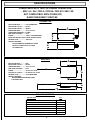
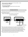
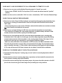
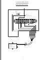
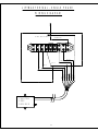
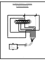
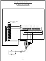
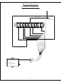
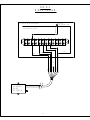
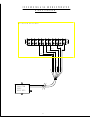
COOKSON OWNER'S MANUAL
VERSION 6
WIRELESS SELF MONITORING
SENSING EDGE SYSTEM
PATENT NO. 6,225,768
9046.DWG ECN 1057 10/27/09 REV 6
SPECIFICATIONS
COMPATIBLE WITH THE FOLLOWING OPERATORS:
- MGJ / H / GH / FDO-A / FDO-B / FDO-A10 / MG / SG
NOT COMPATIBLE WITH OTHER (RF)
RADIO FREQUENCY DEVICES
TRANSMITTER
ENCLOSURE MATL:..............POLYCARBONATE
ENCLOSURE COLOR:...........BLACK
ENCLOSURE RATING:..........NEMA 4
OPERATING TEMP:...............-25° F TO 120° F
OPERATING FREQUENCY:..315 Mhz
MAX OPER DISTANCE:.........50 FT
POWER:..................................9 VOLT LITHIUM BATTERY
EXPECTED BATTERY LIFE:.12 MOS-NORMAL USAGE
ANTENNA TYPE:....................PCB LOOP
SPECIAL FEATURES:
- PROGRAMMABLE TRANSMITTER CODES
- DETECTS LOW BATTERY VOLTAGE
- LED INDICATOR
558
134
134
RECEIVER
483
ENCLOSURE MATL:..............ABS
ENCLOSURE COLOR:...........BLACK
OPERATING TEMP:...............-25° F TO 120° F
MAX OPER DISTANCE:.........50 FT
POWER:..................................24 VOLT AC OR DC
ELECTRICAL CONFIG.:.........OPTIONAL N.O. OR N.C.
ANTENNA TYPE:....................COAX RIGID WIRE
SPECIAL FEATURES:
- PROGRAMMABLE RECEIVER CODES
- LED INDICATORS
334
141
1458
PACKAGE CONTENTS:
DESCRIPTION
QTY
RECEIVER W/WIRING HARNESS
1
TRANSMITTER W/ADHESIVE TAPE
1
BATTERY-9 VOLT LITHIUM
1
ANTENNA
1
#6 RHMS SCREWS
2
WIRE NUT
1
OWNERS MANUAL
1
2
THEORY OF OPERATION
GENERAL DESCRIPTION:
The Phantom Edge is a self monitoring wireless (RF) sensing edge system. A special
communication protocol between the transmitter and receiver allow for additional signals
(other than edge activation) to be sent, such as battery condition and periodic communication
checks. If the unit detects a fault it will convert the operator to supervised mode
(i.e. constant pressure contact on operator close control) indicating that maintenance
is required.
OPERATION:
When the Bottom Bar encounters an obstruction, the Transmitter sends reversing signal to
the Receiver, reversing the door. The unit has self check features, which ensure that the
device is functioning properly.
The unit periodically tests communication by sending a signal at regular intervals.
Low Battery Voltage condition
If any of the above occur (not occur) the unit will enter into Supervised Mode:
Constant pressure will be required on close door operation until fault is corrected.
INSTALLATION INSTRUCTIONS
TO PREVENT ELECTROCUTION DISCONNECT POWER AT FUSE BOX OR CIRCUIT
BREAKER AND OPERATOR BEFORE WIRING
FOLLOW ALL LOCAL BUILDING CODES AND NATIONAL ELECTRICAL CODES. IMPROPER
WIRING COULD CAUSE ELECTROCUTION OR DAMAGE TO CIRCUITRY
NOTES:
BEFORE INSTALLING, VERIFY THAT YOU HAVE A COMPATIBLE OPERATOR.
OPERATOR SHOULD BE COMPLETELY WIRED AND FUNCTIONAL PRIOR TO INSTALLING
PHANTOM EDGE SYSTEM.
TRANSMITTER INSTALLATION:
1) Locate position on Bottom Bar near Sensing Edge pigtail. (Approx. 18" from end of Bottom Bar)
2) Clean the vertical surface where the Transmitter is to be mounted on the Bottom Bar.
3) Remove the protective film from the adhesive backed foam tape and attach it to the back of the
Transmitter box. Attach the Transmitter box to Bottom Bar vertical surface with the label facing
outward, not up.
NOTE: If your installation requires the use of mounting screws, remove the cover from transmitter,
the mounting holes are at the corners (at cover screw locations). DO NOT drill any holes in
the Transmitter box.
4) Connect the sensing edge pigtail to the transmitter per the detail shown on the next page.
3
2 - Wire
B lack
Black
e
Wh it
White
5) Be sure that the battery strap is connected and insert the lithium ion 9 Volt battery into the
cover of the unit, and replace the cover. The green LED light should light indicating that the unit
is functioning properly.
4 - Wire
Connections
Dip Switch #5 "ON"
Connections
Dip Switch #5 "OFF"
RECEIVER INSTALLATION:
CAUTION: DISCONNECT POWER TO OPERATOR
1) Locate the Receiver on the Operator Control Enclosure, with Antenna horizontal and free
of obstructions. Make sure a knock out is accessible, and that mounting screws will clear
internal components of the door operator.
2) Wire to Operator per operator specific wiring diagram. (See Appendix for Wiring Diagrams)
3) Attach Coax Rigid Wire antenna. (The unit will not work unless the rigid antenna is properly attached)
(Units with Motor Covers will require a remote antenna kit to mount the antenna outside the motor cover)
4) Verify that the dip switches in the Receiver and Transmitter are set properly.
5) Verify correct wiring. Restore power to Operator.
CAUTION
BE SURE THAT ALL COAX FITTINGS AND COAX WIRES DO NOT COME IN CONTACT
WITH ANY PART OF THE METAL CONTROL BOX. THIS WILL RESULT IN A SHORT,
AND WILL DAMAGE THE RECEIVER.
4
START UP / TESTING PROCEDURES
RECEIVER
(ON OPERATOR)
INITIAL POWER UP:
1) The unit will be in "Supervised Mode":
Constant pressure required on door CLOSE control
- 2 LED's under the label will be lit.
2) Hold closed door control:
- (D3) "Transmitter Awake" (GREEN) LED will blink when edge is pressed.
- (D8) "Signal Acquired" (GREEN) LED will blink when edge is pressed.
3) When edge is first pressed;
- (D5) "Edge Activation" (AMBER) LED will light for several seconds.
GAGR
4) Receiver will switch to "Normal Mode":
- (D6) "Normal Mode" (GREEN) LED will light.
Door now requires momentary contact for CLOSE control.
D6
D5
D8
D7
LED LEGEND-RECEIVER
D6
GREEN
NORMAL MODE
D5
AMBER
EDGE ACTIVATION
D8
GREEN
SIGNAL ACQUIRED
D7
RED
CHECK BATTERY
TRANSMITTER
(ON BOTTOM BAR)
TEST SENSING EDGE TERMINATION:
1) With door several feet from closed position, disable sensing edge
connection to the Transmitter.
Electrical Edge:
- Unplug quick disconnect plug connecting
Transmitter to Sensing Edge.
- (D7) "Check Battery" (RED) LED should not be lit.
Unit should switch to "Supervised Mode":
Constant pressure required on door CLOSE control.
- (D6) "Normal Mode" (GREEN) LED will turn off.
5
LED LEGEND-TRANSMITTER
D3
GREEN
TRANSMITTER SENDING
3) Open door several feet - Verify that unit is still in "Supervised Mode". Constant
pressure required on door CLOSE control.
4) Reconnect sensing edge to Transmitter.
Unit will switch to "Normal Mode".
- (D6) "Normal Mode" (GRN) LED will light. Door now requires momentary
contact for CLOSE control.
TROUBLESHOOTING
1) Verify address selection dip switches (1 thru 4) are set the same on the Transmitter and Receiver.
2) Check the Battery voltage first.
- Minimum 7 Volts. Replace battery if voltage is at or below minimum.
DIP SWITCH CONFIGURATIONS
RECEIVER SWITCH SETTINGS
ON
1
2
3
4
TRANSMITTER SWITCH SETTINGS
ON
5
1
2
3
4
5
6
7
8
OFF (0)
OFF (0)
ADDRESS
SELECTOR
FACTORY SET
ADDRESS
SELECTOR DO NOT ADJUST
TEST
MODE
ON (1)
ON (2 WIRE, 10K TERMINATION EDGE)
OFF (4 WIRE EDGE)
3) Make sure the antenna is attached to the receiver, and that the "tip" of the antenna is NOT aimed
at the transmitter (the side of the whip antenna is what picks up the signals, not the tip).
4) Do NOT mount the antenna inside a closed metal box; the box will shield the antenna from all
signals, and the receiver will not work as a result. If the receiver must be mounted inside a metal
box, use an antenna extension kit to mount the antenna on the outside of the metal box.
5) Make sure the transmitter is mounted so that when the door is partly open, you are looking
directly at the label on the lid and not looking at the side of the case.
6
DOOR WON'T CLOSE OR REVERSES TO FULL OPEN WHEN IT ATTEMPTS TO CLOSE:
1) Receiver has no power and the Safety Edge relay output is "closed" as a result.
- Ensure that a STEADY 24 VOLTS are present; if DC is used, the red lead must be "positive"
polarity.
2) Make sure the receiver switch #5 in "ON" for 2-wire w/termination; "OFF" for 4-wire Phantom Edge.
DOOR STAYS IN CONSTANT PRESSURE MODE:
1) Receiver has had a Power-On-Reset and has not heard from the sensing edge transmitter since
the power-on, causing a Communication Time-Out Fault (the red LED on the receiver will be
"ON" solid).
* Check that the power to the receiver STAYS on when the limit switches are reached, and when
any of the Operator push buttons are pressed.
2) Receiver has a slowly blinking red LED; this means that the transmitter has a low battery.
* Use a lithium 9-volt battery for cold weather operation; an alkaline battery will work in mild
weather, but has about half the capacity of the lithium types.
3) Receiver has a fast blinking red LED; this means that the transmitter sees a sensing edge
termination fault. If the edge is a 4-wire type, one of the safety edge wires may not be making
contact in the connector in the transmitter, or the sensing edge is faulty. If the edge is of the
terminated 2-wire type, the transmitter is not seeing the terminator resistor.
* Make sure that switch #5 on the transmitter is OFF for 4-wire, and ON for terminated 2-wire.
This unit will not function correctly with a non-terminated 2-wire edge. The terminated edges
can be identified two ways; 1) There will be a blue band around the pigtail as it exits the edge;
2) The edge will measure 10K ohms between the two leads if checked with a multimeter.
DOOR FAILS TO REVERSE WHEN IT CONTACTS AN OBSTACLE:
1) Check that the Door Operator "sensing edge cut-out" switch is correctly adjusted to within 6"
of the floor.
2) Check that the receiver's sensing edge relay output wires are intact and still connected to the
Door Operator's sensing edge input terminals.
3) Check the receiver sensing edge relay output jumper; the jumper should be placed on the N/O
pins for the channel one (green and orange wires) normally-open relay contacts.
7
TO TEST FOR A RF SHORT-RANGE PROBLEM BETWEEN THE TRANSMITTER AND THE RECEIVER:
For a BRIEF TEST, turn on the transmitter's test mode switch, #8, and activate the safety edge to
initiate a transmission. The transmitter will come on and stay on until the switch #8 is turned back
off for normal operation. The receiver Signal Acquired green LED (next to the red Maintenance
Required LED) should come on and stay on while the door is run through its range of motion. The
safety edge should work as usual while in test mode. TURN OFF "TEST MODE" AS SOON AS
POSSIBLE, to avoid undue RF interference and also quickly exhausting the transmitter battery.
REMEMBER:
An ACTIVE SENSING EDGE to the transmitter will cause the receiver sensing edge output relay
to stay ACTIVE.
ALL FAULT CONDITIONS (low battery, edge termination not sensed, communications time-out)
cause the receiver to put the door-operator into Constant Pressure mode.
Check the condition of the receiver's indicator lights at the time of the problem, to quickly
find the cause.
Some locations are much more electrically noisy than others. If the receiver shows signs of
performing a "power-on" light test when the operator's motor starts or stops, or other heavy
equipment in the vicinity seems to be affecting the wireless link, please contact Miller Edge
with the necessary information (mounting location, plus the make and model of the door
operator or other related equipment) to resolve the problem.
8
LABEL AND MANUAL INFORMATION
1) Labeling Requirement
In accordance with the Section 15.19 of FCC Rules, a permanently attached label shall be affixed
to every product in a conspicuous location with the following statement:
"This device complies with part 15 of the FCC Rules. Operation is subject to the following two
conditions: 1) This device may not cause harmful interference, and 2) this device must accept any
interference received, including interference that may cause undesired operation."
(a) For a class A digital device or peripheral, the instructions furnished the user shall include the
following or similar statement, placed in a prominent location in the text of the manual:
"Note: This equipment has been tested and found to comply wit the limits for a Class A digital device,
pursuant to Part 15 of the FCC Rules. These limits are designed to provide reasonable protection
against harmful interference when the equipment is operated in a commercial environment. This
equipment generates, uses, and can radiate radio frequency energy and, if not installed and used in
accordance with the instruction manual, may cause harmful interference to radio communications.
Operation of this equipment in a residential area is likely to cause harmful interference in which
cause the user will be required to correct the interference at his own expense."
(b) For a class B digital device or peripheral, the instructions furnished the user shall include the
following or similar statement, placed in a prominent location in the text of the manual:
"Note: This equipment has been tested and found to comply wit the limits for a Class B digital device,
pursuant to Part 15 of the FCC Rules. These limits are designed to provide reasonable protection
against harmful interference when the equipment is operated in a commercial environment. This
equipment generates, uses, and can radiate radio frequency energy and, if not installed and used in
accordance with the instruction manual, may cause harmful interference to radio communications.
However, there is no guarantee that interference will not occur in a particular installation. If this
equipment does cause harmful interference to radio or television reception, which can be determined
by turning the equipment off and on, the user is encouraged to try to correct the interference by one
or more of the following measures:
- Reorient or relocate the receiving antenna.
- Increase the separation between the antenna and receiver.
- Connect the equipment into an outlet on a circuit different from that to which the receiver is
connected.
- Consult the dealer or an experienced radio/TV techician for help."
2) Information to User
The users manual or instruction manual for an intentional or unintential radiator shall caution the
user that changes or modifications not expressly approved by the party responsible for compliance
could void the user's authority to operate the equipment.
9
APPENDIX INDEX
DESCRIPTION
PAGE
LIFTMASTER
WIRING DIAGRAM - LIFTMASTER GH/H
A-1
WIRING DIAGRAM - LIFTMASTER MGJ
A-2
WIRING DIAGRAM - LIFTMASTER - MGJ 3 PHASE
A-3
WIRING DIAGRAM - FDO-A / FDO-B
A-4
MICANAN
A-5
WIRING DIAGRAM - PRO GH/H
COOKSON
WIRING DIAGRAM - FDO-A10
A-6
WIRING DIAGRAM - MG, MGHL, SGH
A-7
10
LIFTMASTER GH/H
WIRING DIAGRAM
RED
WIRE NUT
FROM
TRANSFORMER
WIRE NUT
(FIELD INSTALLED)
(REMOVE)
1
2
4
3
5
7
L1
10
L2
L3
ORANGE
BROWN
GREEN
BLUE
YELLOW
RED
PHANTOM
EDGE
RECEIVER
A-1
ORANGE
BROWN
GREEN
BLUE
YELLOW
RED
BLACK
BLACK
LIFTMASTER MGJ - SINGLE PHASE
RED
WIRING DIAGRAM
WIRE NUT
(FIELD INSTALLED)
2
3
4
5
7
11
10
12
BLUE
1
(REMOVE)
BROWN
ORANGE
BLACK
PHANTOM
EDGE
RECEIVER
A-2
BLUE
BROWN
YELLOW
BLACK
GREEN
RED
RED
ORANGE
NOT USED
GREEN
LIFTMASTER MGJ - 3 PHASE
WIRING DIAGRAM
TRANSFORMER
(FIELD INSTALLED)
WIRE NUT
RED
BROWN
WIRE NUT
RED (REMOVE)
1
2
4
3
5
7
10
ORANGE
BLACK
BLUE
GREEN
YELLOW
PHANTOM
EDGE
RECEIVER
A-3
BROWN
ORANGE
BLACK
BLUE
GREEN
YELLOW
RED
RED
FDO-A/FDO-B OPERATOR
WIRING DIAGRAM
10
AUX TERMINAL
BLOCK
J9
8
9
J2 CIRCUIT BOARD TERMINALS
13
14
15
16
17
18
19
20
21
22
1
2
3
4
5
6
7
8
9
23
24
BLACK
PHANTOM
EDGE
RECEIVER
A-4
ORANGE
BLACK
BROWN
RED
YELLOW
NOT USED
BLUE
GREEN
BROWN
ORANGE
BLUE
GREEN
RED
4
3
2
1
BLACK
BROWN
5
6
7
J8
10
11
12
WHITE
MICANAN GH/H
WIRING DIAGRAM
RED
(REMOVE)
1
2
4
3
5
6
7
8
9
ORANGE
YELLOW
GREEN
BLUE
PHANTOM
EDGE
RECEIVER
A-5
RED
BROWN
ORANGE
YELLOW
GREEN
BLUE
BLACK
BLACK
WIRE NUT
(FIELD
INSTALLED)
FDO-A10
WIRING DIAGRAM
WALL MOUNTED CONTROL PANEL
WIRE NUT
(FIELD INSTALLED)
1
2
3
4
5
(REMOVE)
YELLOW FROM TERMINAL 14
ON CLOSE CONTACTOR
6
10
11
A2
A1
L1
L2
GREEN
ORANGE
BLACK
BLUE
BROWN
A-6
BLUE
GREEN
ORANGE
YELLOW
BLACK
RED
PHANTOM
EDGE
RECEIVER
BROWN
NOT USED
RED
COOKSON MG & SG SERIES OPERATOR
WIRING DIAGRAM
WALL MOUNTED CONTROL PANEL
1
2
3
4
4A
5
7
6
8
10
9
BLACK
GREEN
BROWN
ORANGE
BLUE
A-7
BROWN
BLACK
GREEN
YELLOW
ORANGE
RED
PHANTOM
EDGE
RECEIVER
BLUE
NOT USED
RED