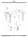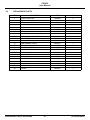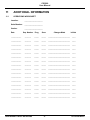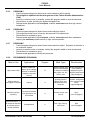
1
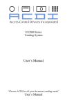
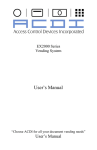
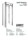
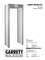
USER MANUAL
CS 5000
Model 11674xx
USA
Garrett Metal Detectors
Security Division
1881 W. State Street
Garland, Texas 75042-6797 USA
Phone:
Fax:
Email:
Website:
1.800.234.6151
1.972.494.1881
[email protected]
garrett.com
International
Garrett Metal Detectors
International Security Division
1881 W. State Street
Garland, Texas 75042-6797 USA
Phone:
Fax:
Email:
Website:
1.972.494.6151
1.972.494.1881
[email protected]
garrett.com
CS 5000
User Manual
MANUFACTURER CAUTION
Read Thoroughly Before Operating
CAUTION! Use of this equipment in a manner not specified by the manufacturer may result in damage to
property or injury to persons.
Electrical:
Installation Category:
Pollution Degree:
Maximum Relative Humidity:
Operating Temperature:
Maximum Altitude:
100 – 240 V~ +10% – -15%
1.0-.5A
50/60 Hz
II
2
95% non-condensing
-4ºF (-20ºC) to +158ºF (70ºC)
3000 meters
CAUTION! CS 5000 must be firmly anchored to the floor to reduce the risk of injury to persons or property
damage due to accidental knock down.
Warning! Battery Safety: The optional Battery Backup Module and the CMA Interface module contain
rechargeable batteries that may contain small amounts of harmful substances.
• Caution: Do not short circuit. Serious burns may result
• Caution: Do not dispose of batteries in a fire. They may explode
• Caution: Do not open or mutilate batteries. They may contain an electrolyte which is toxic and
harmful to the skin and eyes.
• Caution: Replace batteries with the same type and number of batteries as originally installed in the
equipment.
• Caution: Do not put the batteries in trash that is disposed of in landfills. When disposing of the
battery, comply with local ordinances or regulations and your company’s safety standards.
• Recycling centers and retailers with recycling programs may be found at www.rbrc.org.
SYMBOLS:
Alternating
current
Protective
conductor
terminal
CAUTION!
Risk of
electric
shock
CAUTION!
Refer to
accompanying
documentation
Recycle
Garrett Metal Detectors and garrett.com are trademarks and registered trademarks of Garrett Electronics, Inc.
If further assistance is required, please contact the factory using the contact information on the front cover.
©2005 GARRETT METAL DETECTORS
3
PN 1530100 REV D1
CS 5000
User Manual
MEDICAL SAFETY
Garrett Metal Detectors makes every effort to ensure its products are safe for use. Extensive research by Garrett
has produced no information which would indicate that its products have any adverse effects on medical
implants, pregnancy, recording media or magnetic strips. Garrett makes every effort to cooperate with medical
device manufacturers and to communicate with agencies such as the United States Food and Drug
Administration and Health Canada as a means of assuring product safety. The electromagnetic fields produced
by Garrett products are similar to those encountered in the daily environment and meet U.S. and International
standards for electromagnetic emissions.
Garrett recognizes that certain medical devices may have additional requirements which may require special
care. Any recommendations or directives issued by personal physicians or medical device manufacturers
should be followed. If, for any reason, (e.g. doctors orders, etc.), a patron objects to being scanned with a metal
detector, it is recommended that alternative procedures be used.
The following should be considered when developing a security checkpoint screening plan:
•
Traffic Flow - Traffic flow should remain unobstructed as a means of minimizing the time a person remains within the archway of a walk-through metal detector.
•
Alternative Screening - Alternative screening methods such as scanning with a hand held
metal detector, hand searching or denial of access should be clearly defined in checkpoint
screening procedures as approved alternatives to screening with the walk-through metal detec
tor.
•
Personnel Training - Security screening personnel should be instructed in the care of persons
with special medical needs and use of alternative screening methods that meet the requirements
of medical practitioners or medical device manufacturers.
© 2005 GARRETT METAL DETECTORS
4
PN 1530100 REV E
CS 5000
User Manual
TABLE OF CONTENTS
1.
GENERAL DESCRIPTION
6
2.
CONTROLS & MODULES
8
2.1
2.2
2.3
DISPLAY PANEL
TOUCHPADS
INTERNAL MODULES
3.
INSTALLATION INSTRUCTIONS
3.1
3.2
SITE SELECTION
ASSEMBLY
4.
SELF-DIAGNOSTIC TESTS
15
5.
INSTALLATION ADJUSTMENTS
17
6.
SUPERVISOR ADJUSTMENTS
19
7.
SUPERVISOR RESPONSIBILITIES
21
8.
TECHNICAL SPECIFICATIONS
24
9.
MAINTENANCE & REPAIR
26
9.1
9.2
9.3
9.4
9.5
PERIODIC MAINTENANCE
REPAIR
MODULE REPLACEMENT
REPLACEMENT PARTS
WARRANTY
10.
OPERATING INSTRUCTIONS
31
11.
ADDITIONAL INFORMATION
37
11.1
11.2
11.3
11.4
11.5
11.6
11.7
11.8
OPERATIONS WORKSHEET
PROGRAMS
MULTIPLE UNIT OPERATION
AC & DC CONTROL
REMOTE CONSOLES
BATTERY BACK-UP MODULE
STABILIZER BASE
ELECTRICAL WIRING
©2005 GARRETT METAL DETECTORS
8
9
10
12
12
12
26
26
26
29
30
37
38
40
41
42
43
44
45
5
PN 1530100 REV E
CS 5000
User Manual
1.
CS 5000 GENERAL DESCRIPTION
The Garrett CS 5000 Walk-Through Metal Detector features microprocessor-controlled circuitry and
LCD presentation of all calibrating and operating information. It is capable of remote operation and monitoring, when required, and is designed to be easily portable. The unit can be operated on battery power
alone through use of an optional battery pack, which further enhances its portability.
The detector is manufactured by Garrett Metal Detectors in Garland, Texas.
The CS 5000 uses microprocessors in both its detection and control circuitry. These integrated circuits
contain the necessary elements of a small digital computer and are preprogrammed to provide discrimination capabilities that enable the CS 5000 to optimally detect weapons and other devices made of
metal. At the same time, the microprocessors permit the detector to be considerably more sophisticated in its programming and provide greater flexibility in the selectivity of the metals it detects. The detector also features excellent sensitivity, stability and noise rejection. All electronics are built into an overhead panel of the unit to eliminate problems of logistics and reliability often associated with a cableconnected console. The LCD display on the face of the detector's overhead panel reports information
concerning the unit’s calibration and operation. This includes program data, sensitivity settings, operator settings and fault indication. A bright LED bar graph, easily visible from a distance, reports detection levels and separate lights indicate ready and alarm conditions.
All regulation and control functions are “self-prompting” with necessary commands shown automatically on the LCD. The Unit also reports a traffic count on its LCD. The system offers highly flexible capabilities with a continuously variable range of programs including several that have been designed for
specific purposes. Programs are regulated by state-of-the-art touchpads and reported visually on the
LCD. Improved security of the unit’s detection settings comes from an improved system of access
codes. Two levels of codes eliminate the need for bothersome keys for locked doors or other protective
devices, while the CS 5000 circuitry provides precise accuracy of calibration. Access Code #1 is used
by supervisors for selecting programs and sensitivity with Access Code #2 designed for initial set up and
overall control. All settings are encoded by touchpads and remembered in an resettable memory.
Security of the unit’s calibration settings is further protected by a non-resettable sequence code that
© 2005 GARRETT METAL DETECTORS
6
PN 1530100 REV E
CS 5000
User Manual
allows supervisors to keep a log of all changes that are ever made as well as any unsuccessful attempts
to change them. In addition, a tamper indication reports any unauthorized attempts at access. A complete and automatic self-diagnostic program is carried out by the CS 5000 each time the Operate touch
pad is pressed. In addition, the detector utilized self-testing circuitry that continuously monitors the critical functions of the detector, reporting automatically the failure of any element that would affect operation of the unit.
©2005 GARRETT METAL DETECTORS
7
PN 1530100 REV E
CS 5000
User Manual
2.
CONTROLS & MODULES
2.1
DISPLAY PANEL
2.1.1
LED BAR GRAPH
This LED display at the top of the Control Panel indicates the detection intensity which is based on
the amount and composition of metallic objects passing through the unit.
2.1.2
READY LIGHT
This green light appears when power is turned on and the unit is ready to operate. The light will also
indicate when an individual inspection has been completed by the unit and it is ready to accept the
next person. Operators should make certain the green light is visible before any individual is permitted to pass through the detector.
2.1.3
LCD PANEL
Large alpha/numeric LCD below the Bar Graph reports all operating, setup and diagnostic information of the unit. Because the unit is designed to be “user-friendly,” all regulation and control functions
are self-prompting with necessary commands shown on the LCD display.
2.1.4
ALARM LIGHT
This red light appears when the unit detects a targeted amount of metal on an individual, according
to specifications of the Program and Sensitivity levels that have been selected. Operators should be
instructed to respond to all alarms. For any detector to be effective in a security system it is absolutely necessary that the cause of EVERY ALARM be determined.
© 2005 GARRETT METAL DETECTORS
8
PN 1530100 REV E
CS 5000
User Manual
2.2
TOUCHPADS
Eight touchpads on the overhead Control Panel perform all control functions:
2.2.1
STANDBY
When this touchpad is pressed, the unit goes into a low power mode, ready to be returned to full
operation when the OPERATE pad is touched. When STANDBY is displayed on the LCD, the green
READY light is not visible and no processing can take place in the unit. It is important to remember
that the Power Switch located on the Battery Back-up Module (See Section 11.6) should be set to
its OFF position anytime the system is being stored and anytime the system is not in use and is not
connected to AC power for more than 24 hours.
2.2.2
OPERATE
Whenever this touchpad is pressed, the CS 5000 activates all circuits, initiates a self-diagnosis program and places the unit in the Operate Mode within fifteen (15) seconds. This diagnostic program
for instant fault detection can be activated at any time by touching this OPERATE pad. If any faults
are ever found, they will be immediately reported on the LCD display. (See Section 4.)
2.2.3
COUNTER
When this touchpad is pressed, the traffic count is displayed on the LCD display. Pressing and holding this touchpad for ten (10) seconds causes the counter to return to zero (0). Whenever the LCD
is displaying information other than the current traffic count, pressing this touchpad will cause the
count to appear along with the Sequence Number of changes that have been made to
Program/Sensitivity settings. CT (Number) and SEQ (Number) will appear. Each time the
Program/Sensitivity Mode is accessed, the Sequence Code that appears on the LCD will be
advanced one number. It is recommended that a written notation be made on the Operations
Worksheet (see Section 11.1) whenever this code is accessed, explaining reasons for the access.
If the ACCESS touchpad has been pressed and an improper access code has been entered, a * will
appear before the sequence number (SEQ *37). This indicates that an unsuccessful (unauthorized)
attempt has been made to gain access to the Program/Sensitivity setting.
2.2.4
VOLUME
When this touchpad is pressed, the volume level of the unit’s audible alarm will be shown on the
LCD display and the actual volume of the alarm will be heard. The + and - touchpads can be used
by operators to raise or lower the volume. Press OPERATE to return to the operate mode.
©2005 GARRETT METAL DETECTORS
9
PN 1530100 REV E
CS 5000
User Manual
2.2.5
+ AND These touchpads will be used to increase or decrease various numerical settings and for certain
On/Off functions.
2.2.6
PROGRAM
When this touchpad is pressed, the settings for Program and Sensitivity will appear on the LCD display.
2.2.7
ACCESS
The ACCESS touchpad will be used only by supervisory management personnel. It permits changing the Program and Sensitivity codes and also is used to control such functions as synchronization
of multiple units, pulse frequency, tone, etc. (See Section 5.3). The unit further protects security of
control settings by maintaining a non-resettable sequence code that indicates any attempt at seeking access to the settings. When this touchpad is pressed, audio of the system will “chirp” and
ENTER CODE will be displayed on the LCD, prompting the operator to enter an access code. If no
attempt is made to enter a code, the unit will continue chirping for ten (10) seconds and return to
Operate Mode. If the operator enters an incorrect code, audio will sound a Tamper Alarm and
ACCESS DENIED will appear on the LCD for five (5) seconds. An asterisk (*) will appear on the
Sequence Counter indicating that an unsuccessful attempt has been made to access the Installation
or Program/Sensitivity Modes of the unit.
If an operator should inadvertently press the ACCESS touchpad, no further action should be taken
and the unit will return automatically to the Operate Mode in about ten (10) seconds.
SPECIAL NOTE: The above touchpad functions will be available to operators of the detector at all
times. Additional functions such as program and sensitivity settings and other adjustments necessary only at installation time may be selected by pressing the ACCESS touchpad and entering a
security code.
2.3
INTERNAL MODULES
2.3.1
CONTROLLER MODULE
This module (in the center) contains all circuit boards necessary for operation of the detector. Two
cables (A and B) that connect this module to the side panels are to be plugged into the connectors
at the top of each panel. The cover of the Controller Module never needs to be removed except for:
•
•
•
•
Connecting wires to remote alarm relays or synchronization circuitry (See Section 11.3);
Connecting a remote console (See Section 11.5);
Attaching the optional battery back up (See Section 11.6);
Resetting to factory default Access Code (See Section 5.9).
Shown above is a view of the detection unit after the access door has been opened. Three metal
covers protect (from left) the POWER SUPPLY Module, CONTROLLER Module and the BATTERY
PACK Module (Optional).
2.3.2
POWER SUPPLY MODULE
This module contains all circuitry that relates to the power required for operation of the detector. The
Power Cord should be plugged into the Power Supply Module at the connector on the lower left side.
© 2005 GARRETT METAL DETECTORS
10
PN 1530100 REV E
CS 5000
User Manual
POWER
2.3.3
BATTERY PACK MODULE (OPTIONAL)
This module, which includes two (2) 12v batteries and charging circuitry that comprise the optional
battery pack, will be stored behind this cover and connected with the Controller Module. This pack
has a switch which is used to disconnect battery power.
This switch need be placed in the OFF position only during storage or when the unit is not being
used and is not connected to AC power for more than 24 hours. See Section 11.6.1 for installation
instructions.
©2005 GARRETT METAL DETECTORS
11
PN 1530100 REV E
CS 5000
User Manual
3.
INSTALLATION INSTRUCTIONS
3.1
SITE SELECTION
The Garrett CS 5000 should be located on a level, stable floor with no large metal items within three
(3) feet. Any nearby large metallic object can interfere with operation of the detector. Moving metallic objects, such as an escalator or revolving door, close to the detector can cause false alarms. Such
alarms can also be caused by electrical interference from radio telephones, television monitors, powerful electronic motors and transformers, power cables and control circuits.
Garrett’s special built-in circuitry is designed to suppress much of this electronic noise, especially Xray monitor horizontal synchronization signals and closed circuit television. Multiple frequencies permit several CS 5000 units to operate simultaneously, in close proximity.
For information concerning the operation of multiple units, see Section 11.3.
The site for a CS 5000 should be selected with requirements for its pedestrian traffic and use in mind;
i.e. space for waiting lines, operators and areas for hand-scanning. Although the detector is effective
with traffic moving in either direction, best results are obtained when traffic enters from the side opposite to the control touchpads and LCD display.
Locate the archway where it will not be subject to rain, mist or condensation. Protect the power cable
from pedestrian as well as vehicular traffic.
3.2
ASSEMBLY
NOTE: COMPLIANCE WITH REGULATORY STANDARDS REQUIRES THAT A CORD SET BE
USED FOR INSTALLATION.
3.2.1
Lay out the major pieces of the CS 5000, as shown at the right. Make certain all other attachmendevices are included. These should include:
•
•
•
•
•
•
•
•
•
•
•
•
•
Detection Panel A
Detection Panel B
Detection Unit
Crosspiece
Power Cord
1/4-20x3” Screws (8)
Finishing Washers (8)
Warranty Card
User’s Manual
Operator’s Manual
Instruction Video
Access Code Card
Cord Set
© 2005 GARRETT METAL DETECTORS
12
PN 1530100 REV E
CS 5000
User Manual
3.2.2
Install the Power Cord completely through one of the channels at the top of either of the Panels
as shown below. A channel can be found in each of the four corners. Select the corner that will
be convenient in relation to site selection. For overhead power connection, do not insert the
cable through a channel but leave it free at the top.
If using cord set, it must be routed through the channel closest to the Power Module. Care
should be taken to prevent accidental disconnections and exposure to water.
3.2.3
Place the styrofoam packing material on floor as shown and lay the Detection Unit on it with the
touch pad panel facing down. Use four (4) of the Screws and Finishing Washers to connect the
Detection Unit to Panels A and B. Do not tighten.
3.2.4
Open door of the Detection Unit and, first, connect Power Cord. Then, connect Cable A and
Cable B to the Panels as shown.
©2005 GARRETT METAL DETECTORS
13
PN 1530100 REV E
CS 5000
User Manual
3.2.5
Use the remaining screws and washers to attach the Crosspiece to the two panels, as shown
3.2.6
Tighten all eight screws securely with a slotted screwdriver.
3.2.7
With two or more people lift to a vertical position and move to location.
3.3.8
Check for stability of unit, which is important for proper operation and safety. If the floor proves
to be uneven, either shim a corner or slightly loosen the screws connecting the Detection Unit
and Overhead Crosspiece to the Side Panels and adjust as necessary.
3.3.9
Connect to the power line, and proceed with Installation Adjustments (See Section 5.)
© 2005 GARRETT METAL DETECTORS
14
PN 1530100 REV E
CS 5000
User Manual
4.
SELF-DIAGNOSTIC TESTS
The Garrett CS 5000 LCD panel provides valuable information concerning the operation of this unit
and the self-diagnostic program of which it is capable.
4.1
OPERATING INFORMATION
When the unit is placed into operation from the Standby Mode, the following information is reported:
1. Serial Number of the unit will be displayed.
2. Software Version of the unit will be displayed.
3. 50 Hz or 60 Hz will be displayed, indicating current status, if the unit is connected to power line
AC.
4. MASTER or SLAVE will be displayed, indicating current status.
5. CHANNEL designation will be displayed, indicating current status.
6. Program and Sensitivity levels, indicating current status.
4.1.1
SELF-TEST INFORMATION
After the sequence listed above is completed, as well as any time the system power
is connected or any time the OPERATE SELF-TEST touchpad is pressed, a system self-test procedure will be performed. The following information will be displayed on the Display Panel, as necessary. SELF-TEST will be displayed as the unit tests itself automatically. If any of the following six
errors are detected, they will be displayed as shown below:
Example: SELF-TEST...3..4 (Indicates that both Error 3 and Error 4 are occurring.)
4.1.2
CORRECTIVE ACTIONS
4.1.2.1
Error 1: Power failure
Check line voltage and externally connected devices.
4.1.2.2
Error 2: IR Emitter failure
Check connector to Panel A.
4.1.2.3
Error 3: IR Receiver failure
Check connector to Panel B; check for blockage of IR beam at waist level of unit.
4.1.2.4
Error 4: Receiver Balance problem
Check for large metal objects near panels.
4.1.2.5
Error 5: Transmit Energy out of range
Check all connectors; check for very large object near Panel A.
4.1.2.6
Error 6: No Line Sync
If unit is in Slave Mode, check synchronization cable; otherwise, verify that the unit is set to Master.
If an error occurs, follow the procedures noted above and press OPERATE to retest. You will be
prompted SELF-TEST OK when all functions are correct. If problems continue to occur, consult with
your supervisor or factory representative.
The self-diagnostic/reporting cycle described above will be carried out automatically by the unit any
time the OPERATE touchpad is pressed.
©2005 GARRETT METAL DETECTORS
15
PN 1530100 REV E
CS 5000
User Manual
4.1.3
FATAL ERRORS
The system continuously performs several of the tests described above. Errors 1,4 and 5 severely
limit or prohibit the operation of the Magnascanner and are considered Fatal Errors.
If a fatal error is encountered because of component failure, broken wire, etc., the
audible alarm will sound and the LED display will begin to flash. To remedy the situation, press the
OPERATE touchpad, which will initiate the self-diagnostic routine. Note the error(s) that will appear
on the LED and follow instructions stated above. If a solution is not obvious, it will be necessary to
follow the repair procedure described in Section 9.2.
4.1.4
NON-FATAL ERRORS
Errors 2, 3, and 6 may also occur. These failures do not limit the system’s detection capabilities and
the unit will continue to operate. Although the equipment is usable, it is important to identify and
orrect all problems as soon as possible in order to maintain full performance capabilities.
Another error indication is that of a warbling audio when a person is in the archway
(or, for an extended time if the IR Analysis is switched off). This sound indicates that
a large metallic object, such as a wheelchair, stroller, or very large hand-carried object, has “overloaded” the equipment to a degree that it cannot function accurately. If this sound is heard, the operator should see that the problem object is moved away, and the person being inspected should be
required to pass through the archway again after the green READY light appears.
© 2005 GARRETT METAL DETECTORS
16
PN 1530100 REV E
CS 5000
User Manual
5.
INSTALLATION ADJUSTMENTS
The Installation Adjustment Mode, which can be accessed only through use of a four-digit code
(Access Code #2), permits the CS 5000 to be set up properly for best performance in a given operational environment. Various options permit setting the unit for proper operation in conjunction with
other walk-through units or for dealing with typical operation problems.
Default settings, preset at the factory, are indicated below for each of the functions in this mode. Use
the + or - touchpads to regulate any of the functions.
To access the Installation Adjustment Mode for the first time, press the ACCESS touchpad and enter
the factory preset code of 5678. Functions to be set will be displayed in the following sequence:
Pressing ACCESS will scroll through these selections:
5.1
RECEIVER BALANCE
RX BALANCE will be displayed, indicating the balance of the receiving antenna.
A number less than 50 is acceptable. If the number is greater, check the areas around the detector
for large metal objects. If such objects are found, either move the object(s) or move the detector to
eliminate a potential problem.
Press ACCESS for next adjustment or OPERATE to return to normal operation.
5.2
TONE
The alarm tone is initially set at a median level. Through use of the + and - touchpads the tone level
can be raised or lowered. A corresponding number (1 to 9 ) will be displayed on the LCD panel and
the tone that has been selected will be heard. When the desired tone is reached, press ACCESS to
select the next adjustment or press OPERATE to return to normal operation.
5.3
SYNCHRONIZATION
Preset factory option is MASTER. See Multiple Unit Operation in Section 11.3 for directions on proper use of this option when it is necessary.
MASTER enables the unit to operate on its own internally generated synchronization from the
power line.
SLAVE synchronizes the unit to the signal received from another CS 5000 on the Sync terminal (on
the lower center of the Controller Circuit Board).
Press ACCESS for next adjustment or OPERATE to return to normal operation.
5.4
CHANNEL
This feature will allow multiple units to operate in close proximity. It is recommended that when two
(2) units are operated in close proximity that Channels A and B are used. If three (3) or more units
are operated in close proximity, use Channels A, C and D. Do not use Channel B because it may
conflict with Channel C. See Multiple Unit Operation in Section 11.3. Press ACCESS for next adjustment or OPERATE to return to normal operation.
5.5
VIDEO FILTER
This filter permits the unit to function effectively in proximity with video terminals of all types, computer, broadcast, closed circuit, etc. This filter may not apply to certain non-synchronous noise
sources. Settings from 1 to 90 are possible through the use of + and - touchpads. If noise is
observed at your desired operating sensitivity, increment the Video Filter settings to locate the set-
©2005 GARRETT METAL DETECTORS
17
PN 1530100 REV E
CS 5000
User Manual
ting with least interference as observed by fluctuation of the Bar Graph.
Press ACCESS for the next adjustment or OPERATE to return to normal operation.
5.6
RELAY
This feature allows the AC and DC relay circuits to be changed easily to Normally Open (N/O) or
Normally Closed (N/C) to meet installation requirements. Use + and - touchpads to select RELAY
N/C or RELAY N/O (See Section 11.4). Press ACCESS for next adjustment or OPERATE to return
to normal operation.
5.7
ALTER ACCESS CODE #1
This Supervisor Adjustments Code has been preset at the factory at 1234. To change this code:
1. Press the + touchpad.
2. Enter a new four-digit code.
3. The LCD display will prompt REPEAT CODE.
4 . Enter the same four digits of the new code and it will be set and CODE ENTERED OK will be
displayed. (If different digits are entered, the display will indicate INVALID ENTRY, and steps B,
C and D must be repeated.)
Press ACCESS for next adjustment or OPERATE to return to normal operation.
5.8
ALTER ACCESS CODE #2
This Installation Access Code has been preset at the factory at 5678. To change this code:
1. Press the + touchpad.
2. Enter a new four-digit code.
3. The LCD display will prompt REPEAT CODE.
4. Enter the same four digits of the new code and it will be set and CODE ENTERED OK will be
displayed. (If different digits are entered, the display will indicate INVALID ENTRY, and steps B,
C and D must be repeated.)
5. Press OPERATE to exit the Adjustment Mode and enable the detector to be
operated normally. If ACCESS is pressed, this Installation Adjustment cycle will be repeated,
beginning with Receiver Balance.
5.9
RESETTING FACTORY DEFAULT ACCESS CODES
If a code number is ever lost or forgotten, codes may be reset to factory default
settings through the following procedure:
• Open the main cover of the Detection Unit;
• Remove the three (3) screws that hold the Controller Circuit Board cover;
• With power connected and the unit in its Operate Mode press the Access Code Reset button in
the upper center of the circuit board.
• ACCESS CODE #1 will again be 1234 and ACCESS CODE #2 will be 5678.
© 2005 GARRETT METAL DETECTORS
18
PN 1530100 REV E
CS 5000
User Manual
6.
SUPERVISOR ADJUSTMENTS
Several adjustments may be made at the Supervisor’s Level (Access Code #1). These are primarily program/sensitivity settings and the operation of the IR Sensor. These supervisor’s adjustments
can be accessed only through use of a four-digit code (See instructions for altering Access Code #1
under Installation Adjustments, Section 5.7)
To access the Supervisor Adjustment Mode for the first time, press the ACCESS touchpad and the
factory preset code of 1234. The factory default settings of PROG D SENS 160 will be displayed
on the LCD with the program designation blinking. Pressing the ACCESS touchpad will permit scrolling through these selections.
Special Note
For maximum security it is recommended that both Access Code numbers be changed from the factory default settings and that the numbers be known only to those who use them. Record the new
code numbers on the Access Settings card that accompanied this User’s Manual. It is also suggested that codes be changed periodically, especially when any changes are made in personnel with
access to the codes.
6.1
PROGRAM
The programs detailed in Section 11 have been developed for use by the Garrett
CS 5000. These brief descriptions will give some indication of the intent of each program, but a final
judgment on the setting of each individual unit should be determined by the intent of its installation.
After the Program number is accessed through use of the four-digit code, + touchpad can be used
to increase the number, and the - touchpad to lower it. Press ACCESS for next adjustment or OPERATE to return to normal operation.
6.2
SENSITIVITY
This option permits the unit to be adjusted (range of 1 to 200) to the proper level of
sensitivity within a chosen program. Press ACCESS until the SENS and the number are displayed
on the LCD. Use the + and - touchpads to adjust the number. Sensitivity of detection will be
increased as the number is made larger, allowing alarm responses on smaller targets.
After the desired Sensitivity number has been selected, press ACCESS for next adjustment or
OPERATE to return to normal operation.
6.3
IR ANALYSIS
The Garrett CS 5000 utilizes an Infrared Sensor to enhance the operation of the unit in special situations. IR Analysis — ON or OFF appears on the LCD to indicate whether or not the IR Analysis
is being used. The + or - touchpad is used to turn the IR Analysis off and on. Whenever this is done,
it is necessary to press ACCESS for the next adjustment or OPERATE to return to normal operation.
Utilization of the Infrared Sensor is not required for operation of the CS 5000 and may be disabled
if desired.
Several benefits of the sensor are:
1. The units can operate more effectively by correlating signal responses with actual physical
movement. Because this sensor enables the Magnascanner to detect just those individuals and
objects while they are passing through the detector, it can minimize effects of noise and other
influences.
©2005 GARRETT METAL DETECTORS
19
PN 1530100 REV E
CS 5000
User Manual
2. By inhibiting the alarm when no one is in its archway, the IR Analysis greatly
minimizes nuisance alarms. In instances where there is movement of large metal objects near
the exterior of the unit, such as when luggage or supply carts pass by, or when lack of space
requires the unit to be placed very near a conveyor belt of parcel X-ray equipment, the sensor
will effectively inhibit alarms.
3. The IR Analysis provides a warning any time a person passes through the archway when the unit
is in the Set-Up or Self-Test Mode.
4. The IR Analysis enables the detector to count the number of individuals passing through it.
6.4
ALARM LEVEL READING
Computerized circuitry of the Garrett CS 5000 permits the unit to report the minimum
sensitivity level required to cause an alarm for the particular metallic target that is being passed
through the archway. This information can then be used to regulate the unit.
Press the ACCESS touchpad until PLEASE WAIT appears on the LCD Display, followed by ALARM
LEVEL and a number. The target in question should then be passed through the unit. Note the Alarm
Reading number that then appears on the LCD. This is the Sensitivity level that will be necessary
for the unit to sound an alarm on this target. Press the + touchpad to reset the indicator after each
measurement. It is recommended that several measurements of each object in question be made at
various archway positions to obtain the optimum sensitivity level setting.
Press ACCESS for next adjustment or OPERATE to return to normal operation.
© 2005 GARRETT METAL DETECTORS
20
PN 1530100 REV E
CS 5000
User Manual
7.
SUPERVISOR RESPONSIBILITIES
7.1
CALIBRATION
Calibration settings of walk-through metal detectors are dependent upon individual
security screening requirements and, therefore, must be the responsibility of the screening
installation. Program and Sensitivity settings should be established at a level that permits the
detector to detect all forbidden objects that can be reasonably expected to appear at a particular
screening station. Actual forbidden objects should be used as targets for initial calibration.
NOTE: Types of Audio Alarms
Understanding the audio alarms the CS 5000 can sound will enable both supervisors and operators
to understand the detector better and help assure totally accurate screening. Each of three unique
audio alarms is designed to call the operator’s attention to current circumstances:
1. Set-up Alarm: Produces two short beeps as a person is walking through the unit. This alarm
indicates that the metal detector is in a set-up mode and is not ready for operation. Wait for green
READY light (press OPERATE touchpad, if necessary). Person(s) who triggered the Set-up Alarm
must pass through the unit again.
2. Standard Alarm: Occurs when red ALARM light appears and a targeted amount of metal is
detected according to Program and Sensitivity levels.
3. Warble Alarm: Occurs when a large metal mass, such as a wheelchair, furniture or large metal
container is moved through or near the CS 5000. The large amount of metal has
saturated the detector’s receiver circuits and the warble alarm is an indicator that the operator
should correct the situation before allowing anyone to pass through the metal detector.
Calibration and verification can be performed with an Operational Test Piece (OTP), which is an
object similar in size, shape and composition to the smallest forbidden target. Once the walk-through
metal detector is properly calibrated, an OTP may be used to simulate the forbidden objects and verify calibration on a regular basis. The OTP thereby offers a generally accepted means of verifying
calibration without the necessity of having on hand actual weapons at the screening station on a
daily basis.
7.2
FAA TEST PIECE
Garrett manufactures an OTP made to the specifications of the U. S. Federal Aviation Administration
(Garrett Accessory #1600600). This piece is intended to simulate a small firearm.
If the OTP does not represent a specific security requirement then a different test piece(s) should
be considered.
7.3
TESTING
It is imperative that a standard test program be developed for walk-through metal detectors within a
security system. The various tests should be made on a regular basis to ensure that each unit is
properly calibrated and is detecting metal. The OTP has been designed to serve as a basic instrument for use in such a test program.
A test program should include passing the OTP and/or other objects through each metal detector at
various specified heights and horizontal positions, with the OTP (objects) held in different orientations. The number of repetitions required at each level with corresponding successful alarms should
©2005 GARRETT METAL DETECTORS
21
PN 1530100 REV E
CS 5000
User Manual
be established, and this testing system should be adhered to consistently.
Included in the test procedure should be the requirement that the tester be free of all metallic items,
including shoe shanks, prior to arming himself with the OTP. A hand-held metal detector can be used
to confirm that the tester is “clean” of extraneous metallic items.
7.4
ANKLE BOOST
The CS 5000 (Version 2.60 or greater, as displayed in Self-Test, Page 10) incorporates the ability to
adjust the sensitivity at ankle level without increasing sensitivity throughout the passageway. The
factory setting is with standard ankle boost to allow easier passage of shoes containing metal
shanks. Two additional levels of boost are available for higher levels of security.
This adjustment should be used only when sensitivity at ankle level needs to be increased.
7.4.1.
PROCEDURE:
• Disconnect the unit from AC power source (switch off battery back-up module, if installed
• Open access door of detection unit;
• Remove the three (3) screws that hold the controller cover. Move jumpers as shown in the above
diagram to achieve the required level of boost (both jumpers must be set to the same level);
• Replace cover and reconnect power;
• Test unit to assure desired performance level.
© 2005 GARRETT METAL DETECTORS
22
PN 1530100 REV E
CS 5000
User Manual
7.4.2.
APPLICATIONS:
• High: High sensitivity; low traffic volume
• Medium: High Sensitivity; high traffic volume
• Standard: Normal sensitivity; high traffic volume
©2005 GARRETT METAL DETECTORS
23
PN 1530100 REV E
CS 5000
User Manual
8.
TECHNICAL SPECIFICATIONS
8.1
ELECTRONICS
Digital-controlled pulse induction metal detector with microprocessors utilized in both detection and
control circuitry. Designed for tailoring specific programs to fulfill various security applications.
Electronics are modular and designed for easy plug-in and change-out.
8.2
MEMORY
All program selections and settings are maintained in electrically erasable non-volatile memory. The
unit will maintain all settings even when disconnected from power. No battery is required for memory retention.
8.3
OVERHEAD CONTROL UNIT
LCD Display, LED bar graph and control touchpads plus all wiring, connections and electronics are
integrated in a single overhead compartment that eliminates exposed wires and an external control
box.
8.4
CONTROL OUTPUTS
Low-voltage solid state switches. AC switch can control 48V at 100mA; normally open switch is isolated from system ground. DC switch can sink 100mA from a 15V source. Connections to 15V and
system ground are provided for use with internal or external power source.
8.5
CONNECTORS
AC switches, DC switches and synchronization are connected through a screw terminal block.
Remote indicators and remote console are connected through RJ-45 telephone- type connections.
8.6
INDICATORS
READY light indicates unit is operational; ALARM light and audible alarm are activated when target
amount of metal is detected; LED Bar Graph indicates amplitude of alarm signal.
8.7
TRAFFIC COUNTER
Built-in and resettable with current reading easily available on LCD panel.
8.8
TAMPERPROOF
Dual access codes required to set or change the operation of the unit: one level for use by superviors in selecting programs and sensitivity; the other for initial set-up and overall control. Security of
the unit’s calibration settings is further protected by a non-resettable sequence code that allows
supervisors to maintain a precise log of all changes ever made to the program, sensitivity or set-up,
as well as any attempts at changing them. An audible alarm reports any unauthorized attempt at
access.
8.9
CONSTRUCTION
Attractive scratch- and mar-resistant laminate with resilient end caps; control panel and crosspieces
of heavy duty aluminum.
8.10
REGULATORY STANDARDS
Meets (or exceeds) all 1991 Federal Aviation Administration airport applications specifications as
well as all requirements of National Institute of Law Enforcement and Criminal Justice (NILECJ) standard 0601.00, security levels 1-5.
© 2005 GARRETT METAL DETECTORS
24
PN 1530100 REV E
CS 5000
User Manual
8.11
REGULATORY INFORMATION
The Garrett CS 5000 meets or exceeds detection requirements of the National Institute of Law
Enforcement and Criminal Justice Standards #0601.00, levels 1-5, and Federal Aviation
Administration airport application specifications. Programs have been designed specifically to meet
he three-gun test of the FAA and the requirements of the Undetectable Firearm Act of 1991.
The unit also complies with IEC standards for Safety Requirements for Electronic Measuring
Apparatus and meets the Federal Communications Commission Class B standards for noise emission from commercial electrical equipment. It also conforms to the new European Electromagnetic
ompatibility Directive, 89/336/EEC -EN 55011, Group 2, Class B;-EN 50082-1
8.12
WEATHERPROOFING/FOREIGN OBJECT PROTECTION STANDARDS:
Meets IP 31, IEC Standard. Degrees of Protection Provided by Enclosures , CEI 529.
8.13
INTERFERENCE REJECTION
100% sensor coil Faraday shielding. DSP(Digital Signal Processor) automatically suppresses or
eliminates most noises associated with x-ray devices, video monitors and communications equipment, such as radios and walkie talkies. RFI-EMI filters provideattenuation from 10 MHz to 1000
MHz.
8.14
SYNCHRONIZATION
Multiple frequencies permit several CS 5000s to operate simultaneously in close proximity.
8.15
ELECTRICAL
Fully automatic 100 to 240 VAC, 50/60 Hertz, 55 watts; no rewiring, switching or adjustments
required. Power supply meets UL, CSA, TUV and VDE standards. Also complies with IEC standards
for Safety Requirements for Electronic Measuring Apparatus and meets the Federal
Communications Commission Class B standards for noise emission from commercial electrical
equipment.
8.16
DIMENSIONS
• Passageway interior:
• Overall exterior:
• Shipping:
Width: 30” (0.76m) / Height: 80” (2 m) / Depth: 23” (0.57m)
Width: 35” (0.9m) / Height: 87” (2.2m) / Depth: 23” (0.57m)
Width: 33.5” (85.1cm) / Height: 91.5” (223.4cm) / Depth: 6.25”
(15.9cm) / Weight: 129 lbs. (58.6 kg)
•
Througput Rate:
Not limited by electronics; 50-60 detections/minute is reasonable.
•
Optional features:
Remote operating capability (indicators and/or console); battery
back-up module (built-in for portability); Magnadolly (for easy
movement of assembled unit).
©2005 GARRETT METAL DETECTORS
25
PN 1530100 REV E
CS 5000
User Manual
9.
MAINTENANCE & REPAIR
9.1
PERIODIC MAINTENANCE
Periodic maintenance of the equipment requires only inspection for loose or damaged parts and
cleaning of the exterior surfaces.
• Open the access door of the Detection Unit and check that all connectors are
snapped securely and that all screws and nuts are in place.
• Inspect the windows of the IR Sensor to make certain they are not blocked in
any way.
• Check to make certain that the eight (8) screws that attach the Crosspiece and
Detection Unit to the Panels are in place and tight.
• Check to make certain that the archway sits flat on the floor and does not sway
or rock.
• If the power cord or cable to remote devices are at floor level, check for frayed or
broken wires. Replace immediately.
• Clean exterior surfaces with mild soap and water only. If a solvent is necessary for
heavy cleaning, use only denatured alcohol.
• Test the detector daily, or whenever the environment changes.
9.2
REPAIR
There are no user-adjustable controls inside the unit.
Should the equipment ever fail to perform properly, contact the seller for the name of the nearest field
service representative, or contact the factory.
Because the equipment is of modular design, repairs can often be made through replacement of
these plug-in modules. An illustrated parts list follows for your convenience.
If problems are site-related, see Section 3.1 or contact the factory for assistance. Many times these
problems may be resolved through the adjustment of the equipment or through relocation of the
equipment or surrounding objects.
9.3
MODULE REPLACEMENT
The system is built as a series of modules, each of which can be easily removed and replaced.
These modules are tested and calibrated independently, and there is no need for adjustment of any
other electronic assembly when a module is replaced.
It is necessary to test the system carefully to verify operation and the suitability of the product after
any component replacement.
© 2005 GARRETT METAL DETECTORS
26
PN 1530100 REV E
CS 5000
User Manual
POWER SUPPLY &
BATTERY BACK-UP CONNECTORS
ACCESS CODE RESET
FRONT TOUCHPAD CONNECTOR
(BOTTOM OF PC BOARD)
22
RIBBON CABLE CONNECTOR
(BOTTOM OF PC BOARD CONNECTOR)
16
CABLE B CONNECTOR
7
CABLE A CONNECTOR
8
15
5
13
12
9
6
14
23
©2005 GARRETT METAL DETECTORS
27
PN 1530100 REV E
CS 5000
User Manual
17
4
18
20
19
11
21
10
© 2005 GARRETT METAL DETECTORS
28
PN 1530100 REV E
CS 5000
User Manual
9.4.
REPLACEMENT PARTS
ITEM
1
2
3
4
5
6
7
8
9
10
11
12
13
14
15
16
17
18
19
20
21
22
23
DESCRIPTION
Access Control Card
Operation’s Manual
VHS - Instructional Video
Detection Unit
Panel A
Panel B
Display Circuit Board Assembly
Controller Circuit Board Assembly
Power Supply Module 85-265 vac
IR Emitter Circuit Board Assembly
IR Detector Circuit Board Assembly
Cable Assembly, Panel A
Cable Assembly, Panel B
Power Cord 110v 17’
Touchpanel
Ribbon Cable-16 conductor, 6”
Screw 1/4-20x3”
Finishing Washer
Screw 4-40-3/8 flat head, light beige
Crosspiece
Cover with window
Controller Cover
Cord Set
©2005 GARRETT METAL DETECTORS
29
PART #
1562300
1529600
1671600
2225870
2228000
2227970
2325902
2326081
2326300
2333702
2333802
2403700
2403800
9411500
9417500
9504700
9820400
9820500
9822980
9968800
9969590
9984500
9434900
QTY
2
1
1
1
1
1
1
1
1
1
1
1
1
1
1
1
8
8
4
1
2
1
1
PN 1530100 REV E
CS 5000
User Manual
9.5
WARRANTY
Garrett Electronics, Inc. (“Garrett”) warrants that this CS 5000 weapons/metal detector is protected
by the following limited parts and labor warranty for a period of 24 (twenty-four) months (the
“Warranty”).
During this 24-month period Garrett will inspect and evaluate all security equipment returned to its
authorized repair station or factory to determine if the equipment meets performance specifications.
Garrett will repair or replace at no charge to the owner all parts determined faulty. This Warranty does
not cover batteries nor any and all failures caused by abuse, tampering, theft, failure due to weather, battery acid or other contaminants and equipment repairs made by an unauthorized party.
This warranty is expressly in lieu of all other warranties, expressed or implied, including the
warranty of merchantability or fitness for a particular purpose.
The Buyer acknowledges that any oral statements about the merchandise described in this contract
made by representatives, if any such statements were made, do not constitute warranties, shall not
be relied upon by the Buyer and are not a part of this contract for sale. The entire contract is embodied in this writing. This writing constitutes the final expression of the parties’ agreement and is a complete and exclusive statement of the terms of this agreement.
The parties agree that the sole and exclusive remedy against Seller shall be for the repair and
replacement of defective parts. The Buyer agrees that no remedy (including, but not limited to, incidental or consequential damages for lost sales, lost profits, injury to person or property) shall be
available to him.
© 2005 GARRETT METAL DETECTORS
30
PN 1530100 REV E
CS 5000
User Manual
10.
OPERATING INSTRUCTIONS
This Manual is designed to provide all necessary information required for operation of the Garrett
CS 5000 walk-through metal detector. It contains four sections:
• Description of the detector;
• Description of all controls;
• Operators’ responsibilities;
• Basic operating instructions.
10.1
BASIC INSTRUCTIONS
In addition to following all operating procedures as directed by supervisors the operator of a CS
5000 detector has only these responsibilities:
• Assure that the detector is always operating properly;
• Select Off and Operate / On modes;
• Regulate volume of the alarm;
• Read and/or reset the counter;
• Respond to all alarms.
10.2
LCD REPORTS INFORMATION
The LCD on an overhead panel of the detector reports information concerning the unit’s calibration
and operation. This includes program data, sensitivity settings, operator settings and fault indication.
A bright LED bar graph, easily visible from a distance, reports detection levels and separate lights
indicate ready and alarm conditions. All regulation and control functions are “self-prompting” with
necessary commands shown automatically on the LCD. The unit also features the capability to
report a traffic count on its LCD.
Exact control of the unit’s sensitivity is assured by a system with 200 precise and
repeatable steps for each program level, regulated by state-of-the-art touchpads and reported visually on the LCD. Improved security of the unit’s detection settings comes from a totally new system
of access codes. Two levels of codes eliminate the need for bothersome keys for locked doors or
other protective devices, while the CS 5000’s circuitry provides precise accuracy of calibration never
before achieved. Access Code #1 is used by supervisors for selecting programs and sensitivity, with
Access Code #2 designed for initial set-up and overall control. All settings are encoded by touchpads and stored in a resettable memory.
Security of the unit’s calibration settings is further protected by a non-resettable sequence code that
allows supervisors to keep a log of all changes that are ever made to the program, sensitivity or set
up, as well as any unsuccessful attempt at changing them. In addition, a tamper indication reports
any unauthorized attempts at access.
A complete and automatic self-diagnostic program is carried out by the CS 5000 each time the
OPERATE touchpad is pressed. In addition, the detector utilizes self-testing circuitry that enables it
to identify and report automatically the failure of elements that would affect operation of the unit.
10.3
CONTROLS / LCD DISPLAY
Large alpha/numeric display on the Control Panel, backlit for easy viewing, reports
(in words) all regulating, controlling and self-prompting functions of the unit. Because the unit is
designed to be “user-friendly,” all regulation and control functions are self-prompting with necessary
commands shown on the LCD display. Operators should follow instructions of supervisors concerning responses to these commands.
©2005 GARRETT METAL DETECTORS
31
PN 1530100 REV E
CS 5000
User Manual
10.4
READY LIGHT
This green light appears when full power has been turned on and the unit is ready to detect. The light
will also indicate when an individual inspection has been completed by the unit and it is ready to
accept the next person. Operators should make certain the green light is visible before any individual is permitted to pass through the detector.
10.5
ALARM LIGHT
This red light appears when the unit detects a targeted amount of metal on an individual, according
to specifications of the Program and Sensitivity levels that supervisors have entered into its circuitry. This light will appear even when sound volume is inaudible. Operators should follow instructions
of supervisors in responding to alarms. It is absolutely necessary that the cause of EVERY ALARM
be determined.
10.6
TYPES OF AUDIO ALARMS
The CS 5000 has three types of alarms. Each of these unique alarms is designed to call the operator’s attention to current circumstances:
10.6.1
SET-UP ALARM
Produces two short beeps as a person is walking through the unit. This alarm indicates that the metal
detector is in a set-up mode and is not ready for operation. Wait for green READY light (press OPERATE touchpad, if necessary). Person(s) who triggered the Set-up Alarm must pass through the unit
again.
10.6.2
STANDARD ALARM
Occurs when a red Alarm Light appears and a targeted amount of metal is detected according to
Program and Sensitivity levels.
10.6.3
WARBLE ALARM
Occurs when a large metal mass (a wheelchair) moves through or near the Magnascanner. When a
large amount of metal saturates the detector’s receiver circuits the warble alarm indicates that the
situation should be corrected before anyone passes through the detector.
10.7
BAR GRAPH
This LED display indicates the amount of any metal passing through the unit.
10.8
TOUCHPADS
Eight touchpads on the overhead Control Panel perform all control functions.
10.8.1
STANDBY
When this touchpad is pressed, the unit goes into a low power mode, ready to be returned to full
operation when the OPERATE pad is touched. Operators should use all touchpads only as instructed by supervisors.
10.8.2
OPERATE
When this touchpad is pressed, the CS 5000 activates all circuits, initiates a selfdiagnostic program and places the unit in the Operate Mode within 10 seconds.
This diagnostic program for instant fault detection can be activated at any time by touching this
OPERATE pad. If any faults are ever found, they will be immediately reported on the LCD display.
(See Section 4.1.1)
© 2005 GARRETT METAL DETECTORS
32
PN 1530100 REV E
CS 5000
User Manual
10.8.3
COUNTER
Since the current traffic count of the CS 5000 is usually displayed, this touchpad will be needed only
for resetting the counter. Pressing and holding this touchpad for ten (10) seconds causes the counter to return to zero (0). Whenever the LCD displays information other than the current traffic count,
pressing this touchpad will cause the count to appear.
10.8.4
VOLUME
When this touchpad is pressed, the volume level of the unit’s audible alarm will be
displayed on the LCD display. By using the + and - touchpads, operators can raise or lower the volume.
10.8.5
+ AND These touchpads will be used to increase or decrease various numerical settings and for certain
On/Off functions.
10.8.6
PROGRAM
When this touchpad is pressed, the settings for Program and Sensitivity will appear on the LCD display.
All of the preceding touchpad functions will be available to operators of the detector at all times. The
ACCESS touchpad will be used only by supervisors.
10.9
ACCESS TOUCHPAD
This touchpad will be used only by supervisory management personnel. It permits changing the
Program and Sensitivity codes and also is used to control such functions as synchronization of multiple units, pulse frequency and tone. The unit further protects security of control settings by maintaining a non-resettable sequence code that indicates any attempt at seeking access to the settings.
A Tamper Alarm sounds within 10 seconds after the ACCESS touchpad is pressed unless a proper access code is entered. Follow supervisors’ instructions concerning response to this Tamper
Alarm.
10.10
OPERATORS’ RESPONSIBILITIES
• The primary responsibility of any operator is to follow all instructions of supervisors.
• These directives will govern the response of operators to alarms and other situations that will be
encountered. The basic continuing responsibility of the operator will be to ensure that the CS 5000
operates properly at all times as indicated by its LCD panel and that ALL alarms are investigated.
• Remember that the cause of every alarm MUST be determined.
10.11
OPERATORS’ INSTRUCTIONS
All personnel who are associated with the detector should watch a video presentation on the
Magnascanner CS 5000 in addition to studying this User Manual. Carefully following the instructions
in the Manual will help ensure the security of any facility this walk-through detector is expected to
protect.
As described in the CONTROLS section of this manual, CS 5000 controls are located in the top section of the archway. If the green READY light is not visible on the control panel, press the OPERATE touchpad. Operators can also adjust volume of the alarm and can reset the traffic counter.
©2005 GARRETT METAL DETECTORS
33
PN 1530100 REV E
CS 5000
User Manual
10.12
READY LIGHT
The green READY light, located at the top center of the Control Panel indicates that the CS 5000 is
operating. When the green light is showing, power has been turned on and the unit is prepared to
detect metal.
The green READY light must always be on before anyone is permitted to enter the
archway for inspection.
The green light will “wink” whenever anyone breaks the IR beam across the archway or whenever
there is a noise “spike.” If the green READY light should ever go off and remain off, however, the
operator should immediately press the OPERATE touchpad. The detector will then institute a selftest program with results reported on the LCD display. All traffic through the unit must be halted until
the green READY light again appears and remains constant.
10.13
DIAGNOSTIC PROBLEMS
Operators should follow instructions of supervisors concerning their response to any faults ever discovered by the CS 5000 in its self-diagnostic program. Two situations that can be immediately remedied by operators will be indicated by Error 3 and Error 4 on the LCD Panel.
• IR Fail (Error 3): Some obstruction within the unit may be blocking the IR sensor that projects
across the archway. Operator should make certain that the openings for the IR sensor on each side
of the archway, approximately 30 inches from the floor, have not been blocked in any way.
• Receiver Balance (Error 4): This problem could be caused by the presence of a large metal
object that has been placed near the unit. Operators should look for such an object and move it.
Even though these actions may temporarily solve the problems discovered by the self diagnostic program, supervisors should be notified.
While the detector is operating, if a test ever shows a failure that severely limits or prohibits acceptable performance of the unit, the alarm will sound and the LED display will flash. This flashing will
continue until power is removed or the cause of failure is corrected.
10.14
RESPONDING TO ALARMS
When an alarm sounds and the red ALARM light(s) go on, the person passing through the detector
at that time must either be scanned immediately with a SuperScanner or SuperWand hand-held
metal detector or asked to walk through the unit again after removing metal objects from body and
clothing.
If an alarm sounds after the person has removed metal objects, hand scanning is mandatory to find
the source of metal sounding the alarm. This metal must always be found before a person can be
allowed to proceed.
An operator should take nothing for granted! The source that causes any alarm must be discovered.
If a concealed weapon is ever found, the operator should follow instructions that have been given by
supervisors.
10.15
ADJUSTING VOLUME
To adjust the volume of the alarm, the operator should first press the VOLUME touchpad. Then use
the + and - touchpads to regulate the volume. Finally, press the OPERATE touchpad to resume normal operations.
© 2005 GARRETT METAL DETECTORS
34
PN 1530100 REV E
CS 5000
User Manual
10.16
NUISANCE ALARMS
Any metal detector will occasionally register what is called a “nuisance alarm,” triggered by electrical or mechanical noise from the environment. On most walk-through detectors such an alarm can
sound when a person carrying no detectable metal is passing through the archway, or even when
nobody is passing through. Audible nuisance alarms are minimized by the IR Sensor. This sensor
requires that a person must be passing through the unit for any alarm to sound. Because the IR
Sensor can be turned off by a supervisor, operators should always know whether it is functioning or
not.
It is important to remember that after power has been turned on, the CS 5000 is
operating at all times. Its IR Sensor capability inhibits the alarm only when there is no object or person within the archway.
No detector, however, is immune from nuisance alarms caused primarily by electrical
disturbances from large motors, computers, fluorescent lighting or many other sources. An operator
should not be overly concerned about nuisance alarms, but should accept that they can happen and
be ready for them. Of course, it will be necessary to retest any person passing through the detector
when a nuisance alarm is believed to have sounded.
Because of the high level of design quality represented by the CS 5000 and its IR
Sensor, it can be expected to produce relatively few “nuisance alarms” when installed properly.
Nevertheless, operators should always follow instructions from supervisors about reporting them.
On rare occasions a nuisance source might trigger the alarm just as someone is passing through
the detector. An operator should never try to guess about the source of such an alarm, and it should
never be assumed that the alarm is a nuisance. There have been occasions when an individual
would intentionally bump against a detector while passing through it and try to blame an alarm on
the bump.
If an alarm sounds for any reason while a person is passing through the archway, that person must
be asked to walk through the unit again and/or be examined for metallic objects with a hand-held
detector.
There will be no exceptions.
10.17
TAMPER ALARM
Whenever the ACCESS touchpad is pressed, the detector will begin “beeping” for about ten (10)
seconds or until a four-digit numerical access code is entered with the touchpads. During these ten
(10) seconds, the detector will sound an alarm if any person or object passes through the archway.
When less than four touchpads are pressed or if no attempt is made to enter a code within ten (10)
seconds, the detector will return to normal operation. After the ACCESS touchpad is pressed, if an
unauthorized four-touchpad code is entered, an audible Tamper Alarm will sound three loud “beeps.”
The detector will then return to normal operation.
Any attempt at access to the detector’s controls will also be indicated by an increase in the
SEQUENCE code as reported on the LCD display. Any unauthorized attempt at access that activates the Tamper Alarm will be indicated by this symbol (*) adjacent to the SEQUENCE code number. If the Tamper Alarm ever sounds, an operator should follow supervisor’s instructions.
©2005 GARRETT METAL DETECTORS
35
PN 1530100 REV E
CS 5000
User Manual
10.18
COUNTER
If the current traffic count is not being reported on the LCD display, press this touchpad to view it.
Pressing and holding this touchpad for ten (10) seconds enables the operator to return the traffic
counter to zero (0). Supervisors will issue instructions concerning this control and its use by individual operators.
10.19
SUMMARY
It is important that all operators study the guidelines in this section carefully and remember their
basic responsibilities for operating the CS 5000 as stated on the first page:
•
•
•
•
•
Make sure power is turned on;
Make certain the unit is operating properly;
Adjust volume of the alarm;
Read the counter;
Respond to all alarms.
Most important of all is the operator’s responsibility to make certain that every alarm be investigated
and that the reason for that alarm be determined.
The CS 5000 is a fine walk-through metal detector. But, in the end, even an electronic device as
sophisticated as this is only a tool. Ultimate success of its operation is dependent upon:
• The training and diligence of the men and women who operate it;
• The system of which it is a part.
© 2005 GARRETT METAL DETECTORS
36
PN 1530100 REV E
CS 5000
User Manual
11
ADDITIONAL INFORMATION
11.1
OPERATIONS WORK SHEET
Location:
____________________
Serial Number:
____________________
Version:
____________________
Date
Seq. Number
Prog
Sens
Changes Made
Initials
___________
_______
_____
_____
________________________
____
___________
_______
_____
_____
________________________
____
___________
_______
_____
_____
________________________
____
___________
_______
_____
_____
________________________
____
___________
_______
_____
_____
________________________
____
___________
_______
_____
_____
________________________
____
___________
_______
_____
_____
________________________
____
___________
_______
_____
_____
________________________
____
___________
_______
_____
_____
________________________
____
___________
_______
_____
_____
________________________
____
___________
_______
_____
_____
________________________
____
___________
_______
_____
_____
________________________
____
___________
_______
_____
_____
________________________
____
___________
_______
_____
_____
________________________
____
___________
_______
_____
_____
________________________
____
___________
_______
_____
_____
________________________
____
©2005 GARRETT METAL DETECTORS
37
PN 1530100 REV E
CS 5000
User Manual
11.2
PROGRAMS
Note: Although different settings are required for different applications, the manufacturer
finds Program D most effective for high volume high security; Program A for low volume
maximum security; and Program 9 in loss prevention situations and in cases where noise
problems limit performance of custom programs. It is the responsibility of the user to select
and implement that program which is best suited to a particular situation.
11.2.1
PROGRAMS 1-10
• Standard programs designed to detect a broad range of objects.
• Lower numbered programs are primarily for the detection of ferrous objects such as iron, most
stainless steel, etc.
• High numbered programs are primarily for the detection of conductive objects such as those
made of aluminum, zinc, lead, etc.
• Programs 7-9 provide a balanced response to ferrous and conductive objects.
• Program 9 provides good discrimination against foils (cigarette packs, etc.).
• Immunity to external noise is good, making these programs useful in noisy environments.
• Overall discrimination is poor.
• Recommended applications include loss prevention and installations where specific objects
need to be emphasized or ignored.
11.2.2
PROGRAMS 11-15
• Standard programs designed to detect a broad range of objects.
• Lower numbered programs are primarily for the detection of ferrous objects such as iron, most
stainless steel, etc.
• Higher numbered programs are primarily for the detection of large conductive objects such as
those made of aluminum, zinc, lead, etc.
• Programs 14 and 15 provide a balanced response to ferrous and conductive objects.
• Immunity to external noise is poor, making these programs difficult to use in noisy environments.
• Overall discrimination is moderate.
• Recommended applications include loss prevention and installations where specific objects
need to be emphasized or ignored.
11.2.3
PROGRAM A
• Custom program designed to detect the broadest range of objects.
• Emphasis of detection is on conductive objects. This program provides the highest level of
security available in the CS 5000.
• Immunity to external noise is moderate, making this program usable in most environments.
• Discrimination is poor.
• Recommended applications include prisons and other installations where volume requirements allow thorough inspection of each individual.
11.2.4
PROGRAM B
• Custom program designed to detect ferrous and conductive objects equally.
• Immunity to external noise is moderate, making this program usable in most environments.
• Discrimination is moderate.
• Recommended applications include general security.
© 2005 GARRETT METAL DETECTORS
38
PN 1530100 REV E
CS 5000
User Manual
11.2.5
PROGRAM C
• Custom program designed to detect ferrous and conductive objects equally.
• This program is optimized for the three-gun test of the Federal Aviation Administration
(FAA).
• Immunity to external noise is moderate, making this program usable in most environments.
• Discrimination is good, providing the highest throughput rate.
• Recommended applications include airports, schools, courtrooms and other high volume
installations.
11.2.6
PROGRAM D
• Custom program designed to detect ferrous and conductive objects.
• This program provides a level of security that exceeds FAA requirements.
• Discrimination is moderate to good.
• Recommended applications include airports, schools, courtrooms and other installations
requiring the maximum possible security in high volume operation.
11.2.7
PROGRAM E
• Custom program designed to detect ferrous and conductive objects. Emphasis of detection is
on conductive objects.
• Immunity to external noise is moderate, making this program usable in most environments.
• Discrimination is moderate to good.
• Recommended applications include loss prevention.
11.2.8
RECOMMENDED PROGRAMS
When to Use
Applications
High volume traffic
Airports, special
events, private businesses, gov’t buildings,
schools, courthouses,
hospitals, corporate
security
Program
D
Metal Types
Discrimination
Detects FAA test guns, Good to excellent preplus the multi-composivents masking
tion subject to masking designed to ignore
alloy types, iron, alu- common pocket items
minum, steel
(High throughput)
A
Specially tuned to
detect FAA 3 guns,
stainless steel, iron,
aluminum
Excellent - designed to
ignore common pocket
items.
(High throughout)
Correctional Facilities,
Loss prevention, law
enforcement
A
All metal, ferrous, nonferrous
None
(Low throughput)
All applications
9
FAA 3 gun, ferrous,
non-ferrous
Mild
Low Throughput
When maximum
throughput is required
Airports
Maximum security
screening
Alternative when A, C,
D cannot be used due
to extreme environmental conditions
©2005 GARRETT METAL DETECTORS
39
PN 1530100 REV E
CS 5000
User Manual
11.3
MULTIPLE UNIT OPERATION
There are several options for installation of multiple units in close proximity. The following list of
examples will be helpful in determining an appropriate method of connection.
For proper operation, each walk-through metal detector must be set to receive no interference
from adjoining units. This can be determined by observing the bar graph indication of one unit
while switching the remaining unit(s) from Standby to Operate. If the noise flicker increases on
the BAR GRAPH of a unit, then it may be necessary to select another set-up.
11.3.1
CASE I
Description:
• Two (2) units which interfere with each other;
• Both units plugged into same power line (same circuit breaker).
Procedure:
• Set both units to MASTER ;
• Set one unit to CHANNEL A ;
• Set one unit to CHANNEL B.
11.3.2
CASE II:
Description:
• Three (3) or more units that interfere with each other;
•
All units plugged into same power (same circuit breaker).
Procedure:
• Set all units to Master
• Set first unit to CHANNEL A
• Set second unit to CHANNEL B
• Set third unit to CHANNEL D ;
Repeat pattern of CHANNELS A,C, and D for any additional units.
11.3.3
CASE III:
Description:
• Three (3) or more units that interfere with each other;
• Units not plugged into the same power line or units with battery back-up option which may be
required to operate in the absence of AC power.
• With the exception of the first and last units, the SH-3 jumper must be removed. This jumper is
located on the Controller Board Assembly. Refer to the drawing for exact location.
© 2005 GARRETT METAL DETECTORS
40
PN 1530100 REV E
CS 5000
User Manual
Procedure:
• Disconnect units from power line;
• Open Access Door of Detection Unit;
• Remove three (3) screws that hold controller cover;
• Use synchronization wire (18 to 24-gauge, 2 conductor) between units; connect as shown;
• Set the end unit to MASTER CHANNEL A and ensure that this unit is connected to either AC
power or battery power at all times;
• Replace covers and reconnect power;
• Set all other units to Slave;
• Repeat pattern of CHANNELS A, C, and D for any additional units.
11.4
AC & DC CONTROL
11.4.1
AC CONTROL
Connection of an external alarm, locking device or other component may be made as shown
below. The optically-isolated triac output will conduct only during the time that the Red ALARM
light is illuminated. It is recommended that the control not exceed 48Vrms and 100mA. The output
is electrically isolated from ground.
•
•
•
•
11.4.2
Open Access Door of detection unit;
Remove three (3) screws that hold controller cover;
Connect the relay or device to control;
Replace cover and reconnect power.
DC CONTROL
The three drawings that follow illustrate alternate methods of connecting an external device which
has requirements of low voltage direct current. The output is an open collector configuration capable of switching 15V at 100mA or less, which includes connections to computing devices and
other equipment requiring low level DC.
©2005 GARRETT METAL DETECTORS
41
PN 1530100 REV E
CS 5000
User Manual
11.4.2.1
Case I: Use internal power
• Disconnect from AC power;
• Open Access Door of detection unit;
• Remove three (3) screws that hold
controller cover;
• Connect the relay or device to control, as
shown at right;
• Replace cover and reconnect power.
11.4.2.2
Case II: Use external power
• Disconnect from AC power;
• Remove three (3) screws that hold
controller cover;
• Connect the relay or device to control,
• Replace cover and reconnect power.
11.4.2.3
Case III: External logic control
• Disconnect from AC power;
• Open Access Door of detection unit;
• Remove three (3) screws that hold
controller cover;
• Connect the relay or device to control, as
shown at right.
• Replace cover and reconnect power.
11.5
REMOTE CONTROL (OPTIONAL)
A complete remote console with all control functions
that are available on the overhead panel is available
for monitoring and controlling functions of the
Magnascanner CS 5000 from a location apart from
the archway.
This remote console is connected to the overhead
unit with telephone-type cable and RJ 45 connectors
which can be easily concealed behind overhead
panels or in 1/2-inch conduit. The remote control
receives its power from the main detector unit.
Pressing a touchpad on the remote console
achieves the same result as pressing the same
touchpad on the overhead panel, except for the
VOLUME and TONE adjustment.
Regulating alarm volume and tone must be done
separately at the remote console and at each unit it
controls. This enables the audio to be set separately
at the required levels for the console and archway.
A 50-foot cable is standard, but custom lengths are
available.
© 2005 GARRETT METAL DETECTORS
42
PN 1530100 REV E
CS 5000
User Manual
11.5.1
INSTALLATION
• With power disconnected locate archway and console in their desired locations;
• Locate connecting wire and protect from tampering or vandalism, as necessary;
• Plug the wire into the rear of the console;
• Open the Access Door of the detection unit;
• Remove three (3) screws that hold the controller cover;
• Plug the wire into the Circuit Board connector as shown on Page 23;
• Replace covers and connect to power.
11.6
BATTERY BACK-UP MODULE (OPTIONAL)
This optional module is a field-installable assembly that provides power to operate the
Magnascanner CS 5000 for up to twenty (20) hours on a fully charged battery. System software
includes an alarm feature that alerts the operator to a low-battery condition. This ensures that the
unit continues to operate at its peak performance level.
A switch is provided on the side of the battery module to fully disconnect battery power. This
switch whould be set to its OFF position anytime the system is being stored and anytime the system is not in use and is not connected to AC power for more than 24 hours. Standby circuitry will
discharge a fully charged set of batteries in about ten (10) to fifteen (15) days whenever the switch
is not turned off.
11.6.1
INSTALLATION
1. Open the access door of the detection unit;
2. Disconnect the AC power plug from the Power Supply Module;
3. Remove the three (3) screws that hold the Controller Module Cover;
4. Remove the four (4) acorn nuts that are attached to the Battery Pack Module mounting studs;
5. Install the Battery Pack Module and replace the acorn nuts;
6. Disconnect the Power Supply Module connector on the upper left of the Controller Circuit
Board;
©2005 GARRETT METAL DETECTORS
43
PN 1530100 REV E
CS 5000
User Manual
7. Reconnect the Power Supply Module and Battery Pack Module as shown;
8. Reassemble the system and test.
11.7
STABILIZER BASE INSTALLATION
TOOLS REQUIRED
•1/4” Electric Drill Motor
•1/4” (6mm) Nut Driver or Hex Socket
•Tape Measure
•#2 Phillips Screwdriver
PARTS LIST
•2-Mounting Plate
•4-Screw #8x2” Self-Tapping 1/4”
•1-Drill Bit 3/32”
•1-Instruction Sheet
Procedure (NOTE: Install mounting plates before assembling the archway)
11.7.1
Examine the location and determine the best routing for the power cord.
11.7.2
For each panel, remove and discard the two (2) rubber bumpers located on the bottom of the panels. these holes will be used for attaching mounting plates to panels.
11.7.3
Using the supplied 3/32” (2.3mm) drill bit, extend the depth of the mounting holes to 2” (50mm) deep.
11.7.4
Attach the plates (with the edges pointing away from the panel using the supplied 2” long screws.
CAUTION:
The power cord must be installed in the correct Panel location (see Page 8, 3.2.2) before the plate
can be secured. DO NOT PINCH the cord between the panel and the plate. Ensure that the head of
the screw is tight against the plate to prevent the panels from sliding.
11.7.5
Assemble the unit.
11.7.6
Place unit in upright position at selected operating location.
11.7.7
Secure the unit to the floor using 1/4” (6mm) mounting screws (not supplied). The mounting holes in
the plates may be used as a drill guide.
© 2005 GARRETT METAL DETECTORS
44
PN 1530100 REV E
CS 5000
User Manual
Caution: Adjust the width of the unit at the bottom of the panels to 30” (762mm) BEFORE making the
holes in the next step.
11.8
ELECTRICAL WIRING REQUIREMENTS
Magnascanner CS 5000 # 11674XX
Comes with a standard American ground power cord. If the plug must be replaced or removed to hard
wire an AC junction box, use the following wiring list:
Green
Black
White
To Ground
To Line Hot
To Line Neutral
Magnascanner CS 5000 # 11674XX (International)
Comes with a European power cord. If the plug must be replaced or removed to hardwire to an AC
junction box, use the following wiring list:
Green/Yellow
Brown
Blue
©2005 GARRETT METAL DETECTORS
To Ground
To Line Hot
To Line Neutral
45
PN 1530100 REV E
CS 5000
User Manual
© 2005 GARRETT METAL DETECTORS
46
PN 1530100 REV E
© 2005 GARRETT METAL DETECTORS - The Global Leader of Metal Detection Products and Training - 1530100 REV E