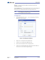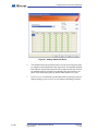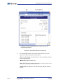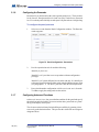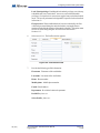
1
TX3 Series
Telephone Access, Card Access,
Configurator and Touch Screen
Configuration and Administration Manual
Version 2.4
LT-995
TX3 Configuration and Administrator Manual
Copyright 2012
1 (165)
Copyright 2012 Mircom Inc.
All rights reserved.
Mircom Configuration and Administrator Guide v.2.4 for Windows 2000/NT/XP®.
This manual, as well as the software described in it, is provided under licence or other agreements
and may be used or copied only in accordance with the terms of such license. The content of this
manual is furnished for informational use only. It is subject to change without notice, and should not
be construed as a commitment by Mircom. Mircom assumes no responsibility or liability for any errors
or inaccuracies that appear in this book.
Except as permitted by such license, no part of this publication may be reproduced, stored in a
retrieval system, transmitted in any form by means electronic, mechanical, using any recorded
media, or any other format without the prior written permission of Mircom.
Microsoft, MS-DOS, Windows, and Windows 2000/NT/XP are either registered trademarks or
trademarks of Microsoft Corporation in the United States and/or other countries.
Mircom
25 Interchange Way
Vaughan, Ontario
L4K 5W3
905.660.4655
Fax:905.660.4113
2 (165)
TX3 Configuration and Administrator Manual
Copyright 2012
Version 2.4
LT-995
Table of Contents
Contents
3 (165)
1
Welcome 8
1.1
1.2
1.3
1.4
1.5
1.6
1.7
1.8
1.9
Introducing the TX3 Suite 9
TX3 Features 10
Touch Screen Features 11
Administrator’s Responsibilities 12
Physical Architecture 12
About This Manual 13
Administrator Interface 14
Touch Screen User Interface 15
Contact Us 16
2
Getting Started 18
2.1
2.2
2.3
2.4
2.5
2.6
2.7
2.8
2.9
2.10
2.11
2.12
PC System Requirements 19
Installation 19
Logging into Administrator Mode 19
Shutting Down the TX3 Touch Screen 20
Main Window Components 21
Changing Passwords 25
Assigning Configurator User Privileges 26
Job Tree 28
Configuring a Job 29
Saving Log Files 37
Updating Firmware 39
Remote Access 41
3
Adding and Connecting to a Panel 48
3.1
3.2
Adding a Panel 49
Connecting to a Panel 51
4
Configuring the Touch Screen Appearance 57
4.1
4.2
4.3
4.4
4.5
4.6
4.7
4.8
Calibrating the Touch Screen 58
Configuring the Touch Screen Appearance 62
Modifying Layouts 64
Creating and Modifying Themes 65
Modifying Videos and Banners 67
Configuring the Advertising Module 79
Modifying More Options 92
Setting Language Options 97
5
Configuring a Telephone Access System Panel 99
5.1
5.2
5.3
5.4
Configuring a Telephone Access System Panel 100
Configuring Inputs 109
Configuring Outputs 111
Establishing Correlations 112
TX3 Configuration and Administrator Manual
Copyright 2012
Version 2.4
LT-995
Table of Contents
5.5
Adding or Modifying Residents 115
6
Configuring a Card Access System Panel 123
6.1
6.2
6.3
6.4
6.5
6.6
6.7
Configuring a Card Access System Panel 124
Configuring Inputs 131
Configuring Outputs 132
Establishing Correlations 135
Adding or Modifying Cards 138
Finding a Card 145
Configuring Access levels 146
7
Defining Schedules and Holidays 150
7.1
7.2
Defining Schedules 151
Defining Holidays 152
8
Monitoring 154
8.1
Monitoring 155
9
APPENDIX 159
9.1
Configurable Touch Screen User Interface Elements 160
Version 2.4
LT-995
TX3 Configuration and Administrator Manual
Copyright 2012
4 (165)
List of Figures
Figure 1.
Figure 2.
Figure 3.
Figure 4.
Figure 5.
Figure 6.
Figure 7.
Figure 8.
Figure 9.
Figure 10.
Figure 11.
Figure 12.
Figure 13.
Figure 14.
Figure 15.
Figure 16.
Figure 17.
Figure 18.
Figure 19.
Figure 20.
Figure 21.
Figure 22.
Figure 23.
Figure 24.
Figure 25.
Figure 26.
Figure 27.
Figure 28.
Figure 29.
Figure 30.
Figure 31.
Figure 32.
Figure 33.
Figure 34.
Figure 35.
Figure 36.
Figure 37.
Figure 38.
Figure 39.
Figure 40.
Figure 41.
Figure 42.
Figure 43.
Figure 44.
Figure 45.
Figure 46.
Figure 47.
Figure 48.
Figure 49.
Figure 50.
Version 2.4
LT-995
Administrator Interface 14
User Interface 15
Main Window Administrator Workspace 21
Tool Bar 24
Change User Password 26
User Management Window 27
Job Tree 28
Create New Job 30
Job Detail Configuration 31
Open Job 32
Backup Jobs 33
Select Job File to Restore 34
Get Job From Panel 36
TX3 Touch Admin Access 37
Configurator Exit Screen 37
TX3 Touch Admin Access 38
Help Menu Navigation 38
Log Files Save Screen 38
Firmware Upgrade 39
Firmware Upgrade - Erasing Current firmware. 40
Firmware Upgrade - Program new firmware 41
Remote Desktop Connection 42
Remote Desktop Connection - General 43
Remote Desktop Connection - Display 44
Remote Desktop Connection - Local Resources 45
Remote Desktop Connection - Local Devices and
Resources 46
Remote Desktop Connection - Log On to Windows 47
Add Panel 49
Create New Job 50
Network Configuration 52
Advanced Network Setup 52
Network Configuration - COM Port 53
Connection Status Icon - Connected 53
Network Configuration - Modem 54
Network Configuration - USB 55
Connection Status Icon - Disconnected 56
PenMount Icon 58
PenMount Control Panel 59
PenMount Device Calibration 59
Standard Calibration 60
Advanced Calibration (9 Points) 61
User Interface Screen Elements 62
Touch Screen Appearance 63
Touch Screen Layouts 64
Touch Screen Themes 65
Touch Screen Customize Theme 66
Touch Screen Videos and Banners 67
Touch Screen Videos and Banners 68
Touch Screen Main Video 69
Touch Screen Help Video 71
TX3 Configuration and Administrator Manual
Copyright 2012
5 (165)
Figure 51.
Figure 52.
Figure 53.
Figure 54.
Figure 55.
Figure 56.
Figure 57.
Figure 58.
Figure 59.
Figure 60.
Figure 61.
Figure 62.
Figure 63.
Figure 64.
Figure 65.
Figure 66.
Figure 67.
Figure 68.
Figure 69.
Figure 70.
Figure 71.
Figure 72.
Figure 73.
Figure 74.
Figure 75.
Figure 76.
Figure 77.
Figure 78.
Figure 79.
Figure 80.
Figure 81.
Figure 82.
Figure 83.
Figure 84.
Figure 85.
Figure 86.
Figure 87.
Figure 88.
Figure 89.
Figure 90.
Figure 91.
Figure 92.
Figure 93.
Figure 94.
Figure 95.
Figure 96.
Figure 97.
Figure 98.
Figure 99.
Figure 100.
Figure 101.
Figure 102.
Figure 103.
Figure 104.
6 (165)
Touch Screen Top Banner 73
Touch Screen Bottom Banner 75
Screen Saver Options 77
Activate Advertising Module 80
Advertising Module Configuration Screen 81
Adding a Media File Part 1 83
Adding a Media File Part 2 84
Edit an Advertising Video 85
Advertisement Scheduling Settings 86
Playlist Scheduling 87
Playlist Copy Options 87
Advertising Report Options 89
Advertising Report Preview Screen 90
Touch Screen More Options 92
Set Touchscreen Time and Date 93
Group Configuration 94
Touch Screen Email Messages 95
Language Editor 97
Language Selection 98
Panel Configuration 101
Panel Configuration - Messages 102
Panel Configuration - Phone Lines 103
Panel Configuration - Calls 104
Panel Configuration - Keypad 105
Panel Configuration - Passcodes 106
Panel Configuration - Advanced 107
Date and Time Options 108
Set New Date and Time 108
Input Configuration 110
Output Configuration 111
Correlation Configuration 113
Add Correlation 113
Resident Configuration List 116
Add Residents 117
Resident Details 118
Resident Details - Keyless Entry 119
Resident Details - Elevator Restrictions 120
Resident Details - Profile 121
Panel Configuration 124
Panel Configuration - Card Reader 126
Date and Time Options 127
Set New Date and Time 127
Access Point Configuration - Timers 128
Access Point Configuration - Advanced 129
Input Configuration 131
Output Configuration 134
Correlation Configuration 135
Add Correlation 136
Correlation activation 138
Card Configuration 139
Add Cards 139
Card Details 141
Card Details Advanced 143
Card Details Profile 144
TX3 Configuration and Administrator Manual
Copyright 2012
Version 2.4
LT-995
Figure 105.
Figure 106.
Figure 107.
Figure 108.
Figure 109.
Figure 110.
Figure 111.
Figure 112.
Figure 113.
Figure 114.
Figure 115.
Figure 116.
Version 2.4
LT-995
Card Details More Profile Info 145
Card Search 145
Access Level Configuration 147
Elevator Control 148
Schedule Configuration 151
Holiday Configuration 153
Network Status 155
Panel Information 156
Set Date and Time 156
Set Panel Passcode 157
Set Date and Time 157
Access Point Status 158
TX3 Configuration and Administrator Manual
Copyright 2012
7 (165)
Welcome
1
Welcome
Welcome provides information about the TX3 suite of building access system
panels. This document introduces these systems, captures typical user and
administrator sessions and presents the requirements on how to begin
configuring each system for the entire TX3 suite.
Note:
Mircom periodically updates panel firmware and software to
add features and correct any minor inconsistencies. For
information about the latest firmware or software visit the
Mircom website at www.mircom.com.
This chapter explains
8 (165)
•
The TX3 Suite
•
TX3 Applications
•
TX3 Configurable Features
•
Administrator Responsibilities
•
Physical Architecture
TX3 Configuration and Administrator Manual
Copyright 2012
Version 2.4
LT-995
Welcome
1.1
Introducing the TX3 Suite
The TX3 product suite consists of the Telephone Access, Card Access and Touch
Screen systems, and the Configurator software. The Telephone and Card Access
Systems are the traditional keypad and card access type of entry systems.
The Mircom Touch Screen (also referred to as Touch Screen) is part of the
Mircom suite of products that provide building ready monitoring, control and
software management solutions for use in the high end multi-tenant residential
market.
The Touch Screen system addresses the need within today’s multi-tenant
residential market for an easy-to-use tenant access system and an easy-to-use
administrator configuration utility. Touch Screen creates an aesthetically
pleasing high quality personalized communication system between residents and
their visitors in a multi-unit dwelling establishment.
1.1.1
Configurator Software
The Configurator is a PC based user friendly graphical application that lets you
configure the Telephone Access, Card Access and Touch Screen Systems.
On the Touch Screen system the Configurator is part of the administrator
interface.
This manual provides the administrator with information about the use and
configuration of the TX3 product suite, and explains how to configure various
components for a new system, including the modification of an existing system.
This manual describes the operation and configuration for the following TX3
Telephone Access and Card Access Systems:
1.1.2
•
TX3-120/200-4 (4x20 LCD)
•
TX3-1000-4 (4x20 LCD)
•
TX3-2000-4 (4x20 LCD)
•
TX3-200-8 (8x20 LCD)
•
TX3-1000-8 (8x20 LCD)
•
TX3-2000-8 (8x20 LCD)
•
TX3-CX Dual Card Reader
ADC and NSL Capability
Touch Screen and the Telephone Access System support full ADC and NSL
telephone connectivity for a single panel or a networked system of panels. A
single panel supports up to five ADC and/or NSL telephone lines.
Version 2.4
LT-995
TX3 Configuration and Administrator Manual
Copyright 2012
9 (165)
Welcome
An ADC connection requires a dedicated subscriber telephone line service
connected to an outside telephone line. This connection lets the visitor call the
tenant and access their voice mail.
An NSL type connection uses the existing building telephone lines for
communication and does not require an outside telephone line. The NSL units
intercept all telephone lines into the building’s suites and communicate directly
to the resident phone. This connection lets the visitor call the tenant and access
their voice mail and call waiting.
1.1.3
Other Controllers
Mircom controllers, such as the Card Access controller, may be networked with
the TX3 system through a peer-to-peer RS-485 network.
1.2
TX3 Features
Features of the TX3 product suite include:
10 (165)
•
An aesthetically pleasing high quality personalized communication
system between residents and their visitors
•
Building ready access control system with full software management in a
user friendly graphical touch enabled interface
•
Easy configuration and customization of tenant access
•
Provisions for postal lock and camera
•
Multilingual Display and Voice Greeting (English, French-Canadian and
Spanish) that provides instructions on how to use the Touch Screen
•
Concierge/Security Desk/Call Reception capability
•
Supports both Auto Dialer (ADC) and NSL
•
Ability to network panels together (peer-to-peer) through RS485
•
Hands free, full duplex communication
•
Flexible one to four digit resident dial codes
•
Dials up to 18 digit telephone numbers
•
Schedule based call restrictions provide more security and flexibility
•
System can be configured locally using the Configurator
•
Remote desktop configuration from any location using the Configurator
•
Upload/download configuration files without taking the whole system offline
•
Records a maximum of 5000 event logs
TX3 Configuration and Administrator Manual
Copyright 2012
Version 2.4
LT-995
Welcome
1.3
Touch Screen Features
The Touch Screen includes the following additional features:
1.3.1
•
Full color Touch Screen display
•
Stainless steel front panel
•
Viewable in direct sunlight
•
150 Watt stereo sound system
•
Ability to play advertisements
•
Ability for visitors to email residents
•
System can be configured locally or remotely using the Touch Screen
administrator interface
Touch Screen Applications
The Touch Screen is a user friendly graphical application that provides one-toone customization of tenant access by enhancing the building entry experience
and creating a truly personalized kiosk session. The Touch Screen graphical
interface includes the ability to provide tenants and guests with specific
advertisements and messages, making it an extremely valuable marketing and
notification tool.
As part of Mircom’s design theme and strategy for the high rise building market,
a visitor at the kiosk sees a series of institution defined advertisement and
promotional messages. These messages form the basis for the personalized
visitor session.
The entire building experience is personalized at the kiosk based on preferences
and marketing campaigns defined by the building management. The
personalization includes:
•
Setting eligible functions and tenant accessibility codes
•
Permitting user access and options
•
Changing the look and feel of the user interface
The Touch Screen provides a way for the institution to easily administer the kiosk
configuration session with the Mircom Touch Screen, and implement tenant
profile updates.
For the administrator, the Touch Screen provides an integrated and
comprehensive database facility to gather, configure and manage various system
components and parameters. This central database manages tenant and system
data, and facilitates the administrator in implementing updates to the tenant
registry.
Version 2.4
LT-995
TX3 Configuration and Administrator Manual
Copyright 2012
11 (165)
Welcome
1.4
Administrator’s Responsibilities
The software lets you configure and monitor activities of all controllers
connected to the TX3 network. The administrator is responsible for the
configuration of the TX3 system, Touch Screen, Configurator and all of the
related components.
When logged in as an administrator all of the following configurable functions
are available:
•
User interface appearance
•
Advertisement content
•
Support for panel functionality with the capability to interface to other
devices - the software fully integrates with the TX3 line of products
The administrator accesses the administrator mode from the Kiosk or computer
and has full rights to every function within the software. The administrator
performs many of the administrative tasks required for installing and managing
the software, including assigning permissions for each level of user. Touch
Screen kiosk personalization depends on preferences defined by the building
management. Additional responsibilities may be provided by the building
manager.
The Configurator software has five password protected user levels. The system
administrator accesses and configures all panels and devices connected to the
panels, and sets up user levels. Users are limited to specific responsibilities such
as adding or removing resident names or defining schedules.
The administrator is responsible for:
1.5
•
modifying user interface appearance
•
providing advertisement content
•
adding new tenants
•
system configuration
•
monitoring the operational health of the system
•
assigning user privileges
Physical Architecture
The Configurator lets you connect a single panel or an entire network of panels,
displaying images of every panel on your site in the Job tree.
You are able to assign additional panels using the Touch Screen or Configurator
interface to recognize and receive data from other panels on your network.
12 (165)
TX3 Configuration and Administrator Manual
Copyright 2012
Version 2.4
LT-995
Welcome
The modular architecture of the TX3 system allows for a flexible, scalable and
customized application, and is determined by the number of building access
points, expected traffic, number of residents, volume of communications,
concurrent connections and kiosk placement.
The network architecture is determined by the expected resident traffic, number
of residents, volume of transactions, concurrent connections and network
capacity. The components of TX3 system, networked together, allows
communication and interaction with the building infrastructure.
By default, Touch Screen is configured with the Telephone Access System Panel.
1.6
About This Manual
This manual provides comprehensive information on the use of the Configurator
and Touch Screen Configurator by the administrator and explains how you may
add additional components and modify and delete existing ones.
This manual assumes that all TX3 system components are setup and operational.
Chapters 1 to 2 provide general information about the TX3 systems.
Chapter 4 provides specific information on how to configure the Touch Screen
User interface.
Chapters 3 to 7 provide comprehensive information on the use of the Touch
Screen and Configurator software.
1.6.1
Additional Documentation
For a description on how to install the Configurator software see LT-973
Configurator Quick Start manual.
For additional documentation, see the following Mircom literature:
Version 2.4
LT-995
•
LT-968 TX3 Telephone Access System User’s Guide.
•
LT-969 TX3 Telephone Access System Installation and Operation
Manual.
•
LT-980 TX3-CX Card Access System Installation and Operation Manual.
•
TX3 Two Door Card Access System Kit Catalogue Number 6531.
•
TX3 Series Elevator Restriction Accessories Catalogue Number 6532.
TX3 Configuration and Administrator Manual
Copyright 2012
13 (165)
Welcome
1.7
Administrator Interface
The Configurator and Touch Screen applications provide a user-friendly
interface for viewing and editing tenant profiles and lets the administrator review
information, generate reports and control various configurations or operations.
The administrator interface is the same interface for both the Configurator and
Touch Screen.
Note:
The Send and Exit button, and Touch Screen tab in the administrator
interface are available only on the Touch Screen application.
Figure 1. Administrator Interface
14 (165)
TX3 Configuration and Administrator Manual
Copyright 2012
Version 2.4
LT-995
Welcome
1.8
Touch Screen User Interface
Touch Screen provides a user-friendly interface for the visitor entering the
building to view and select a tenant from the registry, and email or leave a
message for the tenant.
Figure 2 shows the Touch Screen user interface.
Note:
The user interface in only available on the Touch Screen
application.
Figure 2. User Interface
Version 2.4
LT-995
TX3 Configuration and Administrator Manual
Copyright 2012
15 (165)
Welcome
1.9
Contact Us
Mircom fosters a collaborative support process and environment in providing
early feedback to meet your specific needs.
You can contact us from Monday to Friday 8:00 A.M. to 5:00 P.M. E.S.T.
1.9.1
General Inquiries
For general inquiries call us at the following numbers:
Toll Free: 1-888-660-4655
Local: 905-660-4655
1.9.2
Customer Service
Customer service is available at the following numbers:
Toll Free: 1-888-MIRCOM5
Local: 905-695-3535
Local Fax: 905-660-4113
Toll-Free Fax: 1-888-660-4113
1.9.3
Website
Visit the Mircom website, at www.mircom.com, to find the product information
you are looking for and to learn about troubleshooting, training and technical
support options.
The website provides avenues for customers to ask questions about new and
existing technologies, and receive expert technical support about software and
products. Visit www.mircom.com/chat.
16 (165)
TX3 Configuration and Administrator Manual
Copyright 2012
Version 2.4
LT-995
Welcome
1.9.4
Email
As a customer you quickly become informed on how we can help with new
products and technologies. Contact Mircom at [email protected].
1.9.5
Technical Support
For technical support contact Mircom’s Technical Support Department between
8 A.M. and 5 P.M. (EST) Monday through Friday, excluding holidays.
Toll Free: 1-888-MIRCOM5
Local: 905-695-3535
Local Phone: 905-660-4655
Toll Free Phone: 1-888-660-4655
Email: [email protected]
Version 2.4
LT-995
TX3 Configuration and Administrator Manual
Copyright 2012
17 (165)
Getting Started
2
Getting Started
Getting Started with the Configurator or Touch Screen Configurator is as easy as
starting the software, logging in and using the basic functions.
Once you are familiar with the basic concepts and know your way around the user
and administrator interface, the application helps you to work efficiently and
effectively.
This chapter explains
18 (165)
•
PC System Requirements
•
Installation
•
Logging in
•
Main Window Components
•
Changing Passwords
•
Assigning User Privileges
•
Creating a Job
•
Updating Firmware
•
Establishing Remote Access
•
Shutting Down the TX3 Unit
TX3 Configuration and Administrator Manual
Copyright 2012
Version 2.4
LT-995
Getting Started
2.1
PC System Requirements
On the Touch Screen the Configurator is part of the system and does not require
additional software.
For the PC based Configurator the minimum system requirements are as follows:
2.2
•
Windows 7 (32 bit)
•
Windows XP SP2/ Vista (32 bit)
•
512 RAM
•
1 GHZ CPU
•
600M disk space
•
1 USB port
Installation
The Configurator installation is a fully automated process that is launched from
the Configurator installation CD.
To install the Configurator
1.
2.3
From the CD root directory run setup.exe and follow the instructions.
Once completed the TX3 Configurator icon appears on the desktop.
Logging into Administrator Mode
Logging into the Telephone Access and Card Access Systems requires a
connection to the PC. The PC connects to the controller board using a USB cable
from the computer to the TX3 controller board.
As an alternative, the PC also connects to the controller board modem. The TX3
system is compatible with the TrendNet TFM-560U High Speed USB 2.0 Fax
Modem, the Hiro H50113 56K V.92 USB Fax Modem, and the StarTech
USB56KEM2 56k V.92 USB Fax Modem.
On the Touch Screen system the Configurator is part of the administrator
interface and does not require a connection to a PC based Configurator. Logging
in is done through the Touch Screen interface. An alternative is to use the Remote
Access facility to establish a remote connection to the Touch Screen. See
paragraph 2.12.
When you start Touch Screen for the first time, it starts in user mode. You must
place it in administrator mode to set the application appearance and configure the
panel parameters, connections and passwords.
Version 2.4
LT-995
TX3 Configuration and Administrator Manual
Copyright 2012
19 (165)
Getting Started
See Chapter 5 for a description of the Telephone Access System and Chapter 6 for
a description of the Card Access System.
Note:
To facilitate configuration the previous session displays whenever
you log in.
To log in to Telephone or Card Access Systems
1.
Establish a connection from the PC to the controller using a USB or
modem connection.
2.
Double click the Configurator icon. The administrator access code
window appears.
3.
Enter your username and password to log in to the system and click OK (by
default the user name is administrator and with no password). The Main
Window appears. You are now ready to begin configuration.
4.
Proceed with the rest of the configuration or click Send and Exit from
the Tool Bar to apply the settings and exit the session.
To log in to Touch Screen
2.4
1.
Enter 9999. The administrator access code window appears.
2.
Enter your username and password to log in to the system and click OK (by
default the user name is administrator and with no password). The Main
Window appears. You are now ready to begin configuration.
3.
Proceed with the rest of the configuration or click Send and Exit from
the Tool Bar to apply the settings and exit the session.
Shutting Down the TX3 Touch Screen
To shut down the TX3 unit from the touch screen software navigate to the menu
bar along the top and select the File menu. In the drop down menu that appears
select Shut Down and in the side menu select Shut Down again. Confirm your
selection when the pop-up window appears. The configurator software will shut
down followed by the windows environment and the hardware. Do not
disconnect the power until the full shut down process has been completed.
20 (165)
TX3 Configuration and Administrator Manual
Copyright 2012
Version 2.4
LT-995
Getting Started
2.5
Main Window Components
When using the Configurator for the first time all networked components appear.
By default, Touch Screen is configured to operate with the Telephone Access
System panel. The Touch Screen Main Window lets you access all configurable
functions and consists of the following major areas:
•
Menu Bar
•
Tool Bar
•
Left Pane
•
Right Pane
•
Status Bar
•
Lower Pane
A
B
C
F
D
G
E
A. Menu Bar B. Tool Bar C. Left Pane D. Mode Selection E. Status Bar F. Right Pane G. Lower Pane
Figure 3. Main Window Administrator Workspace
2.5.1
Menu Bar
The Menu Bar lets you access all major Configurator features and consists of the
following six menus:
File Menu
The File Menu lets you setup and define jobs using the following commands:
Version 2.4
LT-995
TX3 Configuration and Administrator Manual
Copyright 2012
21 (165)
Getting Started
New Job. Creates a new Job by selecting a template, copying a current Job or
reading panels from the network. From the template you can select the basic
Touch Screen, Telephone Access or Card Access system.
Open Job. Opens or deletes an existing Job from the database.
Validate Job. Checks if the current Job has any configuration errors. This
operation is done automatically before a Job is sent to the panels.
Backup. Defines the location of the backup folder for a Job. The Backup button
in the Tool Bar uses this location for backing up files.
Restore. Restores user specified jobs from a folder.
Send and Exit. Sends the job to the TX3 Unit and exits out from the configurator.
Exit without Send. Does not send any changes made to the job and exits out from
the configurator.
Shut Down.
Shut Down. Exits from the configurator and shuts down the entire TX3 Unit
Restart. Logs out the current user and restarts the PC.
Exit to Windows. Closes the TX3 software and exits to the windows
environment.
Edit Menu
The Edit menu lets you add, edit and delete panels and components using the
following commands:
Add Panel. Adds panels to the network.
Add Residents. Adds one or more residents to the Job.
Add Cards. Adds one or more cards to the Job.
Edit Residents. Edits the currently selected residents.
Edit Cards. Edits the currently selected cards.
Delete. Deletes the currently selected items. It could be a panel item on the Job
tree, a resident record, or a card record.
Panels Menu
The Panels menu lets you activate panel functionality using the following
commands:
22 (165)
TX3 Configuration and Administrator Manual
Copyright 2012
Version 2.4
LT-995
Getting Started
Connect. Connects to the communication port specified on the Network View as
well as establish connections with the panels currently configured on the
network.
Send Job. Sends the current Job to all panels currently configured on the
network
Get Job. Gets the jobs from all panels currently configured on the network
Firmware Upgrade. Upgrades the firmware of the selected panel.
Reports Menu
The Reports menu lets you generate reports on events, residents and access cards
using the following commands:
Event Log. Generates an event log report from the database. This report shows
in a preview window and can be printed or exported to files in either Excel or pdf
format.
Residents. Generates a resident report from the database. This report shows in a
preview window and can be printed or exported to files in either Excel or pdf
format.
Access Cards. Generates an access card report from the database. This report
shows in a preview window and can be printed or exported to files in either Excel
or pdf format.
Advertising Report. This option is available for the TX3 Touch. Generates an
advertising report from the database. This report can be previewed, printed or
exported to either Excel or pdf formats.
Tools Menu
Tools menu lets you change passwords and set user privileges using the
following commands:
Change Password. Allows the user to change the user password
User Management. This menu item is available only on the Configurator
software to users who have the User Administration access right. Selecting it
launches the User Management dialog. Use this dialog to add or remove system
users, reset their passwords, and modify access rights. A system user is the
person who uses this software application, not to confuse with residents or card
holders.
Languages. This option is available for the TX3 Touch. Selecting this option
allows different languages to be chosen.
Version 2.4
LT-995
TX3 Configuration and Administrator Manual
Copyright 2012
23 (165)
Getting Started
Purchase Advertising Module. This option is available for the TX3 Touch. To
activate the advertising module select this option. For more information refer to
section 4.6, Configuring the Advertising Module.
Help Menu
Help menu provides you with information about the Configurator using the
following commands:
Help Topics. Displays the help content. Pressing the F1 key displays context
sensitive help.
About. Displays the About box of the software. The about box displays
information such as version number of the software and copyright notice.
2.5.2
Tool Bar
A list of ten buttons are available below the Menu Bar for quick access.
Figure 4. Tool Bar
New. Opens the Create New Job Form to create a new Job.
Open. Opens or deletes an existing Job from the database.
Backup. Backs up the current Job to a file in the pre-defined backup folder. The
backup folder location is defined in the Backup File Menu in the Menu Bar.
Add Residents. Opens the Add Residents Form to add one or more resident
records to the system.
Add Cards. Add Cards lets you add one or more cards to the system
Connect. Connects to the panels on the network.
Send. Sends the current Job to the panels on the network.
Get. Retrieves the Job from panels on the network.
Send and Exit. Saves the system information and sends it to the panel, and exists
from the configuration mode to display the Touch Screen user interface. This
button is available only on the Touch Screen Configurator software.
Help. Opens help file.
24 (165)
TX3 Configuration and Administrator Manual
Copyright 2012
Version 2.4
LT-995
Getting Started
2.5.3
Left Pane and Mode Selection
The Left Pane displays the currently selected function from one of the following:
2.5.4
•
Configuration
•
Monitoring
•
Touch Screen (if available)
Right Pane
The Right Pane displays the view associated with the selected Job tree item.
2.5.5
Lower Pane Online Events
The Lower Pane online events displays all events received by the software.
Events may be initiated by the panels or by the software. Only user activity is
logged to the event log.
The view has the following columns:
Time. Time stamp of the event.
Event Description. Description of the event.
Panel. Panel name of this event applies to.
2.5.6
Status Bar
The Status Bar displays status information such as the operation progress and
username.
2.6
Changing Passwords
Your password lets you access the Configurator and prohibits others from using
your account. Once you access the Configurator you can change your
administrator password.
Note:
Version 2.4
LT-995
At any time if you loose or forget the password, call Technical
Support to receive a temporary password. This temporary
password is only valid for the day it is issued.
TX3 Configuration and Administrator Manual
Copyright 2012
25 (165)
Getting Started
To change your administrator password
1.
Click Tools > Change Password. The Change User Password
window appears.
Figure 5. Change User Password
2.7
2.
Type your old password into the Old password text box.
3.
Type a password of 16 characters or less into the New password text
box.
4.
Type the same password into the Verify new password text box.
Assigning Configurator User Privileges
Assigning User Privileges is a Configurator feature that lets you define different
user levels. Once users are defined, system administrators can further organize
them to effectively manage the building.
The system administrator assigns privileges to a particular subordinating level of
user using the User Management window. Only the system administrator is able
to set user levels, add or remove various system users, reset their passwords and
modify access rights.
The various user levels consist of the following:
Operator. An operator has read access only. An operator can monitor live
events and accept access point requests.
User. A user has all of the rights of the operator plus additional reading and
writing card and resident records privileges.
Advanced User. An advanced user has all of the rights of user plus the ability to
read and write schedules, holidays and access levels.
26 (165)
TX3 Configuration and Administrator Manual
Copyright 2012
Version 2.4
LT-995
Getting Started
Manager. A manager has all of the rights of an advanced user plus user
management privileges.
System Administrator. The system administrator can access and configure all
panels and devices connected to the panels, and set up security levels.
Note:
When logging in to a particular user level, only information relevant
to your assigned role will be available.
To assign a user
1.
From the Menu Bar click Tools > User Management. The User
Management window appears.
Figure 6. User Management Window
Version 2.4
LT-995
2.
Enter a User name and Password for the user.
3.
Click Active to enable access rights for the user.
4.
Select a user level from the User Level drop down list.
5.
Click OK to save the information and return to the previous window, or
click Cancel to exit without saving the changes.
TX3 Configuration and Administrator Manual
Copyright 2012
27 (165)
Getting Started
2.8
Job Tree
The Job tree lists all networked components, such the Telephone Access and
Card Access Systems, and provides a list of options to let you add, modify and
delete these configurable components and their characteristics. Job is the
industry-standard term for this type of system.
The Configurator uses a centralized approach to continuously assess the state of
every panel and connected components. This avoids the need for continuous
administrator supervision and facilitates the task of complex configuration of
every system component. The Job tree further simplifies configuration by
providing an overview of the system by listing each configurable item.
Start the configuration by getting familiar with all of the existing networked
components. Selecting a Job tree node displays its corresponding details on the
Right Pane.
Figure 7. Job Tree
2.8.1
Job Tree Elements
When Telephone Access and Card Access Systems are on the network, the Job
tree contains the following elements:
Note:
28 (165)
Right clicking anywhere in the Left Pane lets you add, delete or send
configuration changes to a single panel.
TX3 Configuration and Administrator Manual
Copyright 2012
Version 2.4
LT-995
Getting Started
Job. Displays the Job Detail Configuration view. A Job consists of networks and
their components, such as Telephone Access Systems and Card Access Systems.
Network. Displays the Network Configuration view and consists of networked
components, such as Telephone Access Systems and Card Access Systems. All
connected panels are listed by their network address.
Panel. Displays the Panel Configuration view.
Panel/Access Points. When card access panels are added to the Job file, the
panel access points and card readers are displayed.
Panel/Inputs Outputs. Displays the input and output points of the panel. Inputs
and outputs are labelled, assigned and defined.
Panel/Correlations. Displays the panel Correlation view. Correlations let you
establish an action with an event.
Residents. Displays the Resident List view. Adding a Telephone Access System
panel for the first time to the network establishes the Resident List view.
Cards. Displays the Card List view. Adding a card access panel for the first time
to the network establishes the Card List view.
Access Levels. Displays the Access Levels view. Adding a card access panel for
the first time to the network establishes the Access Levels view.
Schedules. Displays the system and user defined timetables.
Holidays. Displays the Holiday schedules.
2.9
Configuring a Job
The Configurator lets you change panel and device properties. Configure items
individually or sequentially by going through each item from the top to the
bottom of the Job tree.
Configured jobs may be manually validated for any errors, or automatically
validated when sending a Job to the panels.
Configuration information can be sent to individual or multiple panels.
Selecting an item displays that item’s properties in the Right Pane.
By default the Configurator displays the most recently opened Job and network
configuration.
Version 2.4
LT-995
TX3 Configuration and Administrator Manual
Copyright 2012
29 (165)
Getting Started
2.9.1
Creating a new Job
Creating a new Job may be done by directly adding components, by making
modifications to templates or by using information read from the network.
To create a new Job
1.
Select File/New Job from the Menu Bar or New from the Tool bar. The
Create New Job window appears.
Figure 8. Create New Job
2.
Enter the following parameters about the Job:
Job name. Enter the Job name. This entry must be unique.
Description. Provide a description about the Job. This field is mandatory.
Created by. This field is read only and is set to the user when they log in.
Create from a template. Select from an existing template. From this
template you may add or modify components.
Copy from current Job. Select this option to copy information from the
current Job. From the copy you may add or modify components.
30 (165)
TX3 Configuration and Administrator Manual
Copyright 2012
Version 2.4
LT-995
Getting Started
Create by reading panels on the network. Select this option to have the
Configurator automatically retrieve information from all of the networked
panels and components. To use this option you must be connected to the
network.
3.
Click OK to create the new Job and return to the configuration window, or
click Cancel to exit without saving the changes.
To provide details about Job modifications
1.
Select a Job from the Left Pane. The Job Details appears on the Right
Pane.
Figure 9. Job Detail Configuration
2.
2.9.2
Provide a description about the Job in the Description text area and
proceed with the rest of the configuration.
Opening an existing Job
You may open a stored Job and can change existing configurations. These
changes are immediately saved to the database.
Version 2.4
LT-995
TX3 Configuration and Administrator Manual
Copyright 2012
31 (165)
Getting Started
To open an existing Job
1.
To open an existing Job, select File/Open Job from the Menu Bar. The
Open Job window appears.
Figure 10. Open Job
2.
Select a Job and click OK, or click Close to exit without saving the
changes.
To delete an existing Job
32 (165)
1.
To delete a Job permanently from the database, select the Job from the list
and click Delete. A confirmation window appears.
2.
Click Yes to confirm the deletion or No to exit and return to the previous
window.
TX3 Configuration and Administrator Manual
Copyright 2012
Version 2.4
LT-995
Getting Started
2.9.3
Backing up a Job
To backup a Job you must first define the location of the backup folder. You may
back up jobs and event logs to this folder.
To backup a Job
1.
Select File/Backup from the Menu Bar. The Backup Jobs window
appears.
Figure 11. Backup Jobs
2.
Enter the following parameters about the Job:
Backup all jobs. Select this option to backup all jobs in the database to the
backup folder. Backup files have the extension ".t3".
Backup current Job only. Select this option to backup the current Job
only to the backup folder.
Include event logs. Select this option if the event logs are to be backed up
as well.
Folder to store backup files. Select a folder to store the backup files.
3.
2.9.4
Click Backup Now to confirm or Close to exit and return to the
previous window.
Restoring a Job
You may restore previously saved jobs. Select single or multiple Job files with
the .t3 extension.
Version 2.4
LT-995
TX3 Configuration and Administrator Manual
Copyright 2012
33 (165)
Getting Started
To restore jobs
1.
Disconnect from the network and select File/Restore from the Menu
Bar. The Job Restore window appears.
Figure 12. Select Job File to Restore
2.
Select one or more backup files to restore.
Note:
3.
2.9.5
Restore will overwrite open jobs with the same name.
Consequently, saving this Job will overwrite the Job with the same
name in the database.
Click Open to restore the Job or Cancel to exit and return to the previous
window.
Validating a Job
The Configurator automatically validates a Job when it is sent to the panels, but
you have the option to manually validate a Job before sending it to the panels.
To validate a Job
1.
34 (165)
Click File > Validate Job. If there are any errors, an error message
will appear.
TX3 Configuration and Administrator Manual
Copyright 2012
Version 2.4
LT-995
Getting Started
2.
2.9.6
If there are no errors, click Send and Exit from the Tool Bar to apply
the settings and exit the session.
Sending Jobs to Panels
There are two ways to send a Job to a panel. Once panel connectivity is
established, you can send the current Job configuration to an individual panel by
clicking Send to Single Panel or to all panels by clicking Send Job to
Panels.
To reduce programming time, the Configurator determines the minimal set of
configuration changes to send. Sending a Job to all panels only sends the
individual changes. For example, modifying a resident record sends only that
record to the panel.
Sending a Job to a single panel sends all of the configuration information to that
panel including any modifications.
The Configurator does not send the entire configuration to a panel unless:
•
the user has modified the configuration from the front panel or
•
a new panel is added to the Job
To send to all panels
1.
Click Send from the Menu Bar.
2.
Proceed with another configuration or click Send and Exit from the
Tool Bar to apply the settings and exit the session.
To send to a single panel
2.9.7
1.
Right click on a panel in the Job tree and select Send to Single
Panel.
2.
Proceed with another configuration or click Send and Exit from the
Tool Bar to apply the settings and exit the session.
Getting Jobs
When retrieving a Job, the Job tree reads information directly from the panels
currently connected to the network and adds panels to the Job automatically.
Panels do not store the user profile information. In these cases panels use default
information. For a description of user profile see paragraph 5.5 (Telephone
Access) and paragraph 6.5 (Card Access).
Version 2.4
LT-995
TX3 Configuration and Administrator Manual
Copyright 2012
35 (165)
Getting Started
To get a Job
1.
Select Get from the Tool Bar. The Get Job from Panels window appears.
Figure 13. Get Job From Panel
2.
Select the following parameters:
Create a new Job. Scans the network for panels and uses their
configuration information to create a new Job. The Detect new panels
check box is automatically checked.
Create a new Job based on current Job. Copies the current Job and
creates a new Job based on the existing Job. If Detect new panels is
checked, new panels information is also retrieved.
Overwrite current Job. Overwrites the existing information with the
retrieved panel information.
Detect new panels. If selected the software scans the network for any new
panels and reads their configurations.
3.
36 (165)
Click Send and Exit from the Tool Bar to apply the settings and exit
the session.
TX3 Configuration and Administrator Manual
Copyright 2012
Version 2.4
LT-995
Getting Started
2.10
Saving Log Files
2.10.1
For TX3 Touch Software Versions Prior to 1.2.7
1.
From the main touch screen display enter “9999”. The administrator
access code window appears.
Figure 14. TX3 Touch Admin Access
2.
Enter the password to log in to the system and press OK (by default the
there is no password). The main configuration window appears.
3.
In the main configuration window press the Disconnect button.
4.
Navigate to the File menu and select Exit to windows.
Figure 15. Configurator Exit Screen
Version 2.4
LT-995
5.
Navigate to "C:\Program Files\Mircom Technologies\TX3 Touch"
6.
Open the “DataFiles” folder and copy all files with the .log extension and
save them to a usb flash drive.
7.
Open the “Database” folder and copy all files inside and save them to a usb
flash drive.
8.
Restart the TX3 software.
TX3 Configuration and Administrator Manual
Copyright 2012
37 (165)
Getting Started
2.10.2
For TX3 Touch Software Version 1.2.7 or Later
1.
From the main touch screen display enter “9999”. The administrator
access code window appears.
Figure 16. TX3 Touch Admin Access
2.
Enter the password to log in to the system and press OK (by default the
there is no password). The main configuration window appears.
3.
Navigate to the Help menu and select About. The About window appears.
Figure 17. Help Menu Navigation
4.
In the About window select Save Log Files and save them to a usb flash
drive.
Figure 18. Log Files Save Screen
5.
38 (165)
To return to the main touch screen display press Send and Exit.
TX3 Configuration and Administrator Manual
Copyright 2012
Version 2.4
LT-995
Getting Started
2.11
Updating Firmware
The Configurator provides you with a wizard to easily install the latest firmware
into a panel. Firmware updates require that a specialized controller board
hardware initialization procedure be done before using the installation wizard.
Go to the Mircom web site for the latest firmware.
Note:
Ensure the USB cable is directly connected to the USB port on the
controller.
To upgrade the firmware
1.
Initialize the controller for the firmware update.
2.
Click the Disconnect icon in the Tool Bar. The Configurator is
disconnected from the panel.
3.
Select Panels/Firmware Upgrade from the Menu Bar. The
Firmware Upgrade window appears.
Figure 19. Firmware Upgrade
4.
Version 2.4
LT-995
Browse to and select the firmware file.
TX3 Configuration and Administrator Manual
Copyright 2012
39 (165)
Getting Started
5.
Click Next. The Firmware Upgrade Wizard window appears instructing
you to erase the existing firmware.
Figure 20. Firmware Upgrade - Erasing Current firmware.
40 (165)
TX3 Configuration and Administrator Manual
Copyright 2012
Version 2.4
LT-995
Getting Started
6.
Complete the procedure and click Next. The Program new firmware
window appears.
Figure 21. Firmware Upgrade - Program new firmware
2.12
7.
Click Send to download the firmware or Back to repeat the procedure.
8.
Click Next to complete the upgrade and exit the session.
9.
Disconnect the USB cable from the controller and re-activate.
Remote Access
Touch Screen provides you with a facility to access the application remotely
using a Windows XP Pro based PC. This is extremely useful when adding a long
list of resident names and their information to the Touch Screen.
Using remote access requires that the Touch Screen and all TX3 system
components are networked.
Remote Access configuration of the Touch Screen also requires that you
complete the configuration by sending the Job to the panel using the Send
command and then restarting the PC using the Restart PC command from the
menu bar.
Note:
Version 2.4
LT-995
Do not use the Send and Exit command when using Remote Access.
TX3 Configuration and Administrator Manual
Copyright 2012
41 (165)
Getting Started
To establish a remote connection
1.
Select Start/All Programs/Accessories/Remote
Desktop Connection. The Remote Desktop Connection window
appears.
Figure 22. Remote Desktop Connection
42 (165)
TX3 Configuration and Administrator Manual
Copyright 2012
Version 2.4
LT-995
Getting Started
2.
Click Options. The Remote Desktop Connection Options window
appears showing the General tab.
Figure 23. Remote Desktop Connection - General
3.
Provide information for the following:
Computer. Enter the Touch Screen computer IP address.
User name. Enter the user name, administrator.
Version 2.4
LT-995
TX3 Configuration and Administrator Manual
Copyright 2012
43 (165)
Getting Started
4.
Click Display. The Display window appears.
Figure 24. Remote Desktop Connection - Display
5.
44 (165)
Set the remote desktop size by dragging the slider to 1024 x 768 pixels for
the 15 inch Touch Screen display.
TX3 Configuration and Administrator Manual
Copyright 2012
Version 2.4
LT-995
Getting Started
6.
Click Local Resources. The Local Resources window appears.
Figure 25. Remote Desktop Connection - Local Resources
7.
Provide information for the following:
Keyboard. From the drop down list select On the remote
computer. This selection allows to use the Alt-Tab control.
Printers. Uncheck Printers. Touch Screen is not connected to a
printer.
Clipboard. Enabling this selection lets you to use the clipboard.
Version 2.4
LT-995
TX3 Configuration and Administrator Manual
Copyright 2012
45 (165)
Getting Started
8.
In Local devices and resources, click More.... The Local devices and
resources window appears.
Figure 26. Remote Desktop Connection - Local Devices and Resources
46 (165)
9.
Select the Drives check box. You can now copy files from the local PC
to the remote PC.
10.
Click OK to save the information and return to the previous window, or
click Cancel to exit without saving the changes.
11.
Click General. The General window appears (Figure 23).
12.
Click Save As... to save this configuration to a file on the PC. For
convenience save the file to the desktop.
TX3 Configuration and Administrator Manual
Copyright 2012
Version 2.4
LT-995
Getting Started
13.
Press Connect. The remote computer login window appears.
Figure 27. Remote Desktop Connection - Log On to Windows
2.12.1
14.
Click OK. No password is required. Once connected the remote desktop
Touch Screen window appears giving you full control of the Touch
Screen. In this mode Touch Screen is not accessible by visitors.
15.
Proceed with the configuration. Once completed click Send.
16.
Click File > Restart PC. Touch Screen restarts in user mode and the
Remote Access session ends.
Ending Remote Access at any time
To exit the Remote Access configuration session at any time without applying the
changes click File > Restart PC.
To exit the Remote Access user session at any time, enter the configuration mode
and click File > Restart PC.
Version 2.4
LT-995
TX3 Configuration and Administrator Manual
Copyright 2012
47 (165)
Adding and Connecting to a Panel
3
Adding and Connecting to a Panel
The Touch Screen application and Configurator software lets you connect to any
panel on the network. Once you connect to a panel, you can monitor and
configure activities of all controllers connected to the TX3 network and add
resident and card information.
This chapter explains
48 (165)
•
Adding a panel
•
Connecting to a panel
TX3 Configuration and Administrator Manual
Copyright 2012
Version 2.4
LT-995
Adding and Connecting to a Panel
3.1
Adding a Panel
The first step in setting up the panel is to add the panel to the network. Once a
Touch Screen, Card Access or Telephone Access panel is added to the network,
access configuration information can be entered.
Note:
When adding additional panels ensure the selected panel matches
the panel and model you wish to connect to.
For information about the installation of the Telephone Access and Card Access
Systems, refer to the manuals shipped with the system and on the Mircom website
(www.mircom.com).
To add a panel to the network
1.
Right click anywhere on the tree and select Add Panel. The Add
window appears.
Figure 28. Add Panel
2.
Provide the following information:
Panel model. Click the drop down list and select a panel.
Address. This field displays the remaining available panel addresses.
Click the drop down list and select the panel address. Ensure that this
address matches the panel address.
Label. Provide a name for the panel.
3.
Version 2.4
LT-995
Click Add to add the panel and return to the configuration window, or
click Close to exit without saving the changes.
TX3 Configuration and Administrator Manual
Copyright 2012
49 (165)
Adding and Connecting to a Panel
To add a Touch Screen panel to the network
1.
Select File/New Job from the Menu Bar or New from the Tool bar. The
Create New Job window appears.
Figure 29. Create New Job
2.
Enter the following parameters about the Job:
Job name. Enter the Job name. This entry must be unique.
Description. Provide a description about the Job. This field is mandatory.
Created by. This field is read only and is set to the user when they log in.
3.1.1
3.
Select Create from a template / Basic Touch Screen
System.
4.
Click OK to create the new Job and return to the configuration window, or
click Cancel to exit without saving the changes.
Deleting a panel from the network
Deleting a panel from the network removes it entirely from the system.
Configuration information inside the panel remains unchanged.
To delete a panel from the network
1.
50 (165)
Select a panel and right click. The Delete Panel window appears.
TX3 Configuration and Administrator Manual
Copyright 2012
Version 2.4
LT-995
Adding and Connecting to a Panel
2.
3.2
Click Delete. A confirmation window appears. Click Yes to confirm the
deletion or No to exit and return to the main window.
Connecting to a Panel
The network configuration option lets you set the parameters required for the PC
to communicate with a single panel or a network of panels using a COM port,
Modem, USB or RS-485 connection. By default, the Touch Screen is connected
to the internal Telephone Access System Panel.
Note:
Whenever configuring a network, first disconnect from that
network.
Each controller must be set with a level 3 passcode. By default this passcode is
3333.
Note:
The level 3 panel passcode must match the network passcode in
order to connect to that panel. The level 3 passcode is initially set at
the panel.
When a panel is successfully connected, a message displays in the Lower Pane
Online Events indicating it is currently online. If unsuccessful an error message
appears.
Once connected the Connect toolbar button shows the ‘connected’ icon and
you can begin adding resident and card information.
To establish a network connection
1.
If connected, Click Disconnect from the toolbar.
2.
Establish the USB, modem, COM or RS-485 connection form the PC to
the controller.
Note:
Version 2.4
LT-995
When using an RS-485 connection select Com Port from the PC
connection list.
TX3 Configuration and Administrator Manual
Copyright 2012
51 (165)
Adding and Connecting to a Panel
3.
Click Network. The Network Configuration window appears.
Figure 30. Network Configuration
4.
Click Advanced. The Advanced Network Setup window appears.
Figure 31. Advanced Network Setup
5.
Enter the following parameters:
Network passcode. The network passcode is used for logging into each
panel. All panels on the network must use this passcode as their highest
level passcodes.
Network timeout. The timeout is the time the software will wait for each
panel to respond to a communication command. Increasing this value may
help when there are many communication errors.
52 (165)
TX3 Configuration and Administrator Manual
Copyright 2012
Version 2.4
LT-995
Adding and Connecting to a Panel
6.
Proceed with a USB, COM port or modem configuration as described in
the following paragraphs.
To connect to a panel using the COM port
1.
Select Com Port from the PC connection list. The Port Details window
appears.
Figure 32. Network Configuration - COM Port
2.
Select the COM port number. The speed is fixed set at 115200 baud. Data
bit settings are fixed at no parity, 8 data bits and 1 stop bit.
3.
Click Connect from the Tool Bar. Once connected the connection icon
appears.
.
Figure 33. Connection Status Icon - Connected
Version 2.4
LT-995
TX3 Configuration and Administrator Manual
Copyright 2012
53 (165)
Adding and Connecting to a Panel
To connect to a panel using the modem
1.
Select Modem from the PC connection list. The Modem window appears.
Figure 34. Network Configuration - Modem
2.
Enter the following parameters:
Modem. Select a modem currently configured into the PC.
Phone #. Provide the telephone number the panel is connected to. If
necessary use a comma for a pause.
Note:
The pause length depends on the type of modem.
Extra initialization commands. Provide any extra modem initialization
commands. The characters "AT" are automatically added before the
initialization commands. Refer to the manufacturer’s modem
documentation for additional information.
3.
54 (165)
Click Connect from the Tool Bar to connect.
TX3 Configuration and Administrator Manual
Copyright 2012
Version 2.4
LT-995
Adding and Connecting to a Panel
To connect to a panel using the USB port
1.
Select USB from the PC connection list. The USB window appears. The
connection automatically establishes and no settings are required. The
software looks for the USB to the serial virtual COM port configured on
the PC. The speed and data bit settings are the same as the COM port
option.
Figure 35. Network Configuration - USB
2.
3.2.1
Click Connect connect.
Disconnecting from a Network
The disconnection process, by pressing the Disconnect icon, is opposite to that of
connection process. The software logs out each panel and disconnects from the
communication port.
The disconnection process is also automatically invoked when closing a Job or
closing the software.
Note:
Version 2.4
LT-995
Some configuration functions, such changing the panel address or
model, require you to disconnect from the network. Whenever you
are doing any kind of configuration ensure whether disconnection
from the network is required.
TX3 Configuration and Administrator Manual
Copyright 2012
55 (165)
Adding and Connecting to a Panel
To disconnect from the panel network
1.
Click the Disconnect button. The Disconnect icon disappears,
indicating that it is ready to connect.
Figure 36. Connection Status Icon - Disconnected
2.
56 (165)
Proceed with the configuration.
TX3 Configuration and Administrator Manual
Copyright 2012
Version 2.4
LT-995
Configuring the Touch Screen Appearance
4
Configuring the Touch Screen
Appearance
Touch Screen lets you easily change the appearance of the user interface by
setting the system parameters and options.
This chapter explains how to
Version 2.4
LT-995
•
Calibrate the Touch Screen
•
Configure the Touch Screen
•
Create and Modify Layouts
•
Create and Modify Themes
•
Modify Videos and Banners
•
Configure the Advertising Module
•
Configure System Options
•
Configure the Date and Time
•
Configure Resident Groups
•
Configure Email Messaging
•
Set Language Options
TX3 Configuration and Administrator Manual
Copyright 2012
57 (165)
Configuring the Touch Screen Appearance
4.1
Calibrating the Touch Screen
The TX3 Touch Screen does not require calibration for the initial setup.
However, over time and with continued use it may require re-calibration. The
resistive Touch Screen hardware is controlled by third party software from
PenMount. Calibration cannot be performed remotely and must be performed
locally at each terminal. This section explains how to calibrate the Touch Screen
using the PenMount software.
Entering the PenMount Control Panel
1.
From the TX3 Touch software log in as administrator.
2.
From the menu bar select File > Exit to Windows. Press Yes to
confirm.
Figure 37. PenMount Icon
3.
Select the PenMount icon from the Windows taskbar notification area.
From the menu that appears select Control Panel. The PenMount
Control Panel appears.
Note:
58 (165)
If the PenMount icon does not appear in the taskbar notification area
ensure that the taskbar notification area is fully expanded.
TX3 Configuration and Administrator Manual
Copyright 2012
Version 2.4
LT-995
Configuring the Touch Screen Appearance
Calibrating the Touch Screen
Figure 38. PenMount Control Panel
1.
From the PenMount Control Panel select the device to configure in the
Device tab. If the device does not appear ensure that it is connected and
turned on, then press Refresh.
2.
Once the device is selected press Configure. The Device Calibration
window will appear.
Figure 39. PenMount Device Calibration
Version 2.4
LT-995
TX3 Configuration and Administrator Manual
Copyright 2012
59 (165)
Configuring the Touch Screen Appearance
3.
Two types of calibration options exist. For most touchscreens the
Standard Calibration option is sufficient. However, over time,
the Advanced Calibration option may be required. To perform
standard calibration proceed to step 4. To perform advanced calibration
skip to step 5.
4.
To start standard calibration press on the Standard Calibration
button in the Device Calibration window. The PenMount software will
display a series of four red squares on the screen which must be pressed in
sequence. Use your finger or a stylus to press each square. After each
square is pressed calibration will complete. Skip to step 8.
Figure 40. Standard Calibration
60 (165)
5.
The Advanced Calibration option can be configured to use between 4 to 25
points of calibration from the Advanced Mode box in the Device
Calibration window. Increasing this value increases the accuracy of the
calibration. From the Advanced Mode box select the number of points of
calibration to use.
6.
The Plot Calibration Data option displays a linearity comparison graph
after advanced calibration has been completed. Black lines on the graph
indicate the ideal linearity while the blue lines show the calculated
linearity. Select Plot Calibration Data to display this graph at the end of
calibration.
TX3 Configuration and Administrator Manual
Copyright 2012
Version 2.4
LT-995
Configuring the Touch Screen Appearance
7.
To begin the advanced calibration select Advanced Calibration
from the Device Calibration window. The PenMount software will display
a series of red squares on the screen which must be pressed in sequence.
Use your finger or a stylus to press each square. A stylus is recommended
for increased accuracy. After each square is pressed calibration will
complete.
Figure 41. Advanced Calibration (9 Points)
8.
Version 2.4
LT-995
Once calibration has been completed press OK in the Device Calibration
window. Press OK again in the PenMount Control Panel. Quickly press
twice on the TX3 Touch icon from the desktop to restart the TX3 Touch
software.
TX3 Configuration and Administrator Manual
Copyright 2012
61 (165)
Configuring the Touch Screen Appearance
4.2
Configuring the Touch Screen Appearance
Touch Screen customization lets you set the layout, theme, videos and banners,
and specific user options. If the preset appearance is not to your liking, you can
change it.
The appearance of all Touch Screen screen elements are configurable and may be
saved and re-applied. Figure 42 shows the user interface configurable screen
elements.
A
I
B
G, H
C
F
D
E
A. Main Video B. Help Button C. Call Reception D. Keyboard E. Bottom Banner F. Clock/Language
Selection G. Call Resident H. Disconnect I. Resident Scroll Buttons
Figure 42. User Interface Screen Elements
62 (165)
TX3 Configuration and Administrator Manual
Copyright 2012
Version 2.4
LT-995
Configuring the Touch Screen Appearance
To configure the Touch Screen appearance
1.
Log in as administrator and select the Touch Screen tab from the
bottom of the Left Pane. The Touch Screen Options window appears.
Figure 43. Touch Screen Appearance
2.
Version 2.4
LT-995
Proceed with the configuration of Layouts, Themes, Videos and
Banners or More Options as described in the following sections.
TX3 Configuration and Administrator Manual
Copyright 2012
63 (165)
Configuring the Touch Screen Appearance
4.3
Modifying Layouts
Layouts lets you determine how each of the major screen areas are arranged
and portrayed, and may be selected from existing templates or customized.
To change the current Layout
1.
From the Left Pane select Touch Screen > Layout. The Layouts
menu appears.
Figure 44. Touch Screen Layouts
2.
From the Screen Layouts select one of the four available layouts.
3.
From the Virtual Keyboards select from one of the following
options:
Full size. Displays the keyboard in full size.
Full + Num. Displays the keyboard in full size with numbers.
Simple. Displays the keyboard in basic formatted lettering.
64 (165)
4.
To show the dial codes on the residential directory select Show dial
codes box.
5.
To enable resident names to exceed 15 characters in length select the
Enable long names box.
6.
Proceed with another configuration or press Send and Exit from the
Tool Bar to apply the settings and exit the session.
TX3 Configuration and Administrator Manual
Copyright 2012
Version 2.4
LT-995
Configuring the Touch Screen Appearance
4.4
Creating and Modifying Themes
Themes lets you set the screen font size, color and element attributes. Selections
may be saved as.thm files and existing themes may be imported. You can
accept an existing customized theme or modify it as necessary. Preset themes are
fixed and cannot be modified.
A test option lets you look at the selection without exiting the administrator
mode.
See the Appendix for a detailed description of the user interface elements.
To create or modify themes
1.
From the Mode Selection press Touch Screen > Themes. The
Themes menu appears.
Figure 45. Touch Screen Themes
Note:
Version 2.4
LT-995
Preset themes can not be modified, only exported.
TX3 Configuration and Administrator Manual
Copyright 2012
65 (165)
Configuring the Touch Screen Appearance
2.
Select a custom theme and press Customize. The Customize Theme
window appears showing the font and color selections.
Figure 46. Touch Screen Customize Theme
66 (165)
3.
Select the font size and color for the user interface elements. For a
complete list of all the configurable user interface elements see the
appendix.
4.
Press Import to retrieve an existing theme or press Export to save the
theme to a file.
5.
Press Test to display the selection without exiting the administrator
mode.
6.
Press OK to apply the settings and return to the previous window.
7.
Proceed with another configuration or press Send and Exit from the
Tool Bar to apply the settings and exit the session.
TX3 Configuration and Administrator Manual
Copyright 2012
Version 2.4
LT-995
Configuring the Touch Screen Appearance
4.5
Modifying Videos and Banners
Videos and Banners lets you define and select the multi media options for the
Touch Screen user interface. There are four different locations where media can
be displayed. Figure 28 shows the customized Touch Screen user interface areas.
Media can be in any of the following video or still image formats: .avi, .wmv,
.swf, .jpg, .jpeg, .bmp, or .png.
A. Top Banner B. Main Video C. Help Video D. Bottom Banner E. Screen Saver
Figure 47. Touch Screen Videos and Banners
Version 2.4
LT-995
TX3 Configuration and Administrator Manual
Copyright 2012
67 (165)
Configuring the Touch Screen Appearance
To set videos, screen saver and banners
1.
From the Mode Selection select Touch Screen > Videos and
Banners. The Videos and Banners window appears.
Figure 48. Touch Screen Videos and Banners
2.
68 (165)
Configure the Main Video, Help Video, Top Banner, Bottom
Banner and Screen Saver as described in the following sections.
TX3 Configuration and Administrator Manual
Copyright 2012
Version 2.4
LT-995
Configuring the Touch Screen Appearance
To set the Main Video
1.
Select Main Video. The Media Selection window appears.
Figure 49. Touch Screen Main Video
2.
To determine how you want the video to display, define the following
parameters:
Single Video. To show a single media file on the main video display select
this option.
Advertising. To show multiple media files on the main video display
select this option. Refer to 4.6 Configuring the Advertising Module.
Select File. Press Select File to select a media file from a directory.
Original Size. This option appears when image or flash file formats are
selected. Selecting this option displays the image in its original size.
Resize to fit. This option appears when image or flash file formats are
selected. Selecting this option resizes the image to fit within the display
area.
Version 2.4
LT-995
TX3 Configuration and Administrator Manual
Copyright 2012
69 (165)
Configuring the Touch Screen Appearance
3.
To preview the selected media file use the video control buttons to play,
stop, pause, rewind or fast forward.
4.
To adjust the volume use the volume control buttons to the right of the
media perview window.
5.
Press OK to apply the settings and exit the Media Selection window session
or press Cancel to exit without selecting the media file.
6.
Proceed with another configuration or press Send and Exit from the
Tool Bar to apply the settings and exit the session.
Note:
70 (165)
To disable the Main Video select a layout that does not include it.
Refer to 4.3 Modifying Layouts.
TX3 Configuration and Administrator Manual
Copyright 2012
Version 2.4
LT-995
Configuring the Touch Screen Appearance
To set the Help Video
1.
Select Help Video. The Media Selection window appears.
Figure 50. Touch Screen Help Video
2.
To determine how you want the video to display, define the following
parameters:
Single Video. To show a single media file on the help video display select
this option. For the help video this is the only option available and it is
automatically selected.
Advertising. This option is disabled for help videos.
Select File. Press Select File to select a media file from a directory.
Original Size. This option appears when image or flash file formats are
selected. Selecting this option displays the image in its original size.
Resize to fit. This option appears when image or flash file formats are
selected. Selecting this option resizes the image to fit within the display
area.
Version 2.4
LT-995
TX3 Configuration and Administrator Manual
Copyright 2012
71 (165)
Configuring the Touch Screen Appearance
3.
To preview the selected media file use the video control buttons to play,
stop, pause, rewind or fast forward.
4.
To adjust the volume use the volume control buttons to the right of the
media perview window.
5.
Press OK to apply the settings and exit the Media Selection window session
or press Cancel to exit without selecting the media file.
6.
Proceed with another configuration or press Send and Exit from the
Tool Bar to apply the settings and exit the session.
Note:
72 (165)
To disable the Help Video select a layout that does not include it.
Refer to 4.3 Modifying Layouts.
TX3 Configuration and Administrator Manual
Copyright 2012
Version 2.4
LT-995
Configuring the Touch Screen Appearance
To set the Top Banner
1.
Select Top Banner. The Media Selection window appears.
Figure 51. Touch Screen Top Banner
2.
To determine how you want the video to display, define the following
parameters:
Single Video. To show a single media file on the top banner display select
this option. Only image or flash file formats can be used for the top banner.
Advertising. This option is disabled for the top banner.
Disable. To disable the top banner select this option.
Select File. Press Select File to select a media file from a directory.
Show Text. To display customized text select this option and enter the
desired text into the text field on the right. When this option is selected only
text appearing in the text field will be displayed and any previously
selected media files will not be displayed in the top banner. The text format
can be edited as described in 4.4 Creating and Modifying Themes.
Version 2.4
LT-995
TX3 Configuration and Administrator Manual
Copyright 2012
73 (165)
Configuring the Touch Screen Appearance
Original Size. Selecting this option displays the image or flash object in
its original size.
Resize to fit. Selecting this option resizes the image or flash object to fit
within the display area.
74 (165)
3.
Press OK to apply the settings and exit the Media Selection window session
or press Cancel to exit without selecting the media file.
4.
Proceed with another configuration or press Send and Exit from the
Tool Bar to apply the settings and exit the session.
TX3 Configuration and Administrator Manual
Copyright 2012
Version 2.4
LT-995
Configuring the Touch Screen Appearance
To set the Bottom Banner
1.
Select Bottom Banner. The Media Selection window appears.
Figure 52. Touch Screen Bottom Banner
2.
To determine how you want the video to display, define the following
parameters:
Single Video. To show a single media file on the bottom banner display
select this option.
Advertising. To show multiple media files on the bottom banner display
select this option. Refer to 4.6 Configuring the Advertising Module.
Disable. To disable the bottom banner select this option.
Select File. Press Select File to select a media file from a directory.
Original Size. This option appears when image or flash file formats are
selected. Selecting this option displays the image in its original size.
Resize to fit. This option appears when image or flash file formats are
selected. Selecting this option resizes the image to fit within the display
area.
Version 2.4
LT-995
TX3 Configuration and Administrator Manual
Copyright 2012
75 (165)
Configuring the Touch Screen Appearance
76 (165)
3.
To preview the selected media file use the video control buttons to play,
stop, pause, rewind or fast forward.
4.
To adjust the volume use the volume control buttons to the right of the
media perview window.
5.
Press OK to apply the settings and exit the Media Selection window session
or press Cancel to exit without selecting the media file.
6.
Proceed with another configuration or press Send and Exit from the
Tool Bar to apply the settings and exit the session.
TX3 Configuration and Administrator Manual
Copyright 2012
Version 2.4
LT-995
Configuring the Touch Screen Appearance
To set the Screen Saver
1.
Select Screen Saver. The Media Selection window appears.
Figure 53. Screen Saver Options
2.
To determine how you want the video to display, define the following
parameters:
Single Video. To show a single media file over the entire display while the
screen saver is active select this option.
Advertising. To show multiple media files on the over the entire display
while the screen saver is active select this option. Refer to 4.6 Configuring
the Advertising Module.
Disable. To disable the screen saver select this option.
Select File. Press Select File to select a media file from a directory.
Wait. Specify the amount of time before the screen saver begins playing.
Original Size. This option appears when image or flash file formats are
selected. Selecting this option displays the image in its original size.
Version 2.4
LT-995
TX3 Configuration and Administrator Manual
Copyright 2012
77 (165)
Configuring the Touch Screen Appearance
Resize to fit. This option appears when image or flash file formats are
selected. Selecting this option resizes the image to fit within the display
area.
78 (165)
3.
To preview the selected media file use the video control buttons to play,
stop, pause, rewind or fast forward.
4.
To adjust the volume use the volume control buttons to the right of the
media perview window.
5.
Press OK to apply the settings and exit the Media Selection window session
or press Cancel to exit without selecting the media file.
6.
Proceed with another configuration or press Send and Exit from the
Tool Bar to apply the settings and exit the session.
TX3 Configuration and Administrator Manual
Copyright 2012
Version 2.4
LT-995
Configuring the Touch Screen Appearance
4.6
Configuring the Advertising Module
The advertising module is an optional addition to the TX3 Touch. It allows
advertisements in the form of videos, images or animations to be displayed on the
touch screen. Advertising media can play on the Main Video display, the Bottom
Banner display and as a Screen Saver over the entire display.
The advertising module allows property managers to recoup the costs of their
telephone entry and card access security system by selling advertising time on
their kiosks in high traffic lobbies and entrance ways.
The subsequent sections explain the following configuration options:
Version 2.4
LT-995
•
Enabling the Advertising Module
•
Advertising Module Configuration
•
Adding an Advertisement
•
Editing an Advertisement
•
Deleting an Advertisement
•
Advertisement Priority Settings
•
Advanced Advertisement Options
•
Setting the Screen Saver Timer (Screen Saver selection only)
TX3 Configuration and Administrator Manual
Copyright 2012
79 (165)
Configuring the Touch Screen Appearance
Enabling the Advertising Module
To activate the software for the advertising module follow the steps below.
1.
From the menu at the top of the screen press Help > Purchase
Advertising Module. The Purchase TX3 Touch Advertising
Module window appears.
Figure 54. Activate Advertising Module
2.
Press Generate Licensing File. The Save Advertising Licensing
File window will appear.
3.
Select a location to save the file and press Save.
Note:
Remember where the licensing file is saved.
4.
Once the licensing file has been saved contact customer support at the
number provided on the Purchase TX3 Touch Advertising Module
window or from the information provided in 1.9 Contact Us.
5.
Once customer support has been contacted a license key will be generated
and provided to you. Enter the provided key into the Purchase TX3 Touch
Advertising Module window. Press Activate to activate the advertising
module.
Note:
80 (165)
The key is only valid for the unit for which the licensing file was
generated. Each unit requires a separate key to activate its
advertising module.
TX3 Configuration and Administrator Manual
Copyright 2012
Version 2.4
LT-995
Configuring the Touch Screen Appearance
Advertising Module Configuration
From the Videos and Banners tab the advertising module can be activated for the
following selections: Main Video, Bottom Banner and Screen Saver.
All media files are listed in the Video Files list. The files in this list are played
based on each file’s associated schedule.
A. Video Location Tabs B. Video Files List C. Configuration Buttons
D. Screen Saver Timeout E. Playlist Editing Buttons F. Scheduling Window
Figure 55. Advertising Module Configuration Screen
The advertising module configuration screen has several components:
Video Location Tabs. Advertisements can be played on three screen
locations: Main Video, Bottom Banner and Screen Saver. Select a tab to
configure advertisement options for each screen location.
Video Files List. Media files are listed here. The files in this list are played
during the three hour time slots that they have been assigned to in the
scheduling window. See Scheduling Window.
Configuration Buttons. These buttons allows video files to be added,
removed and configured.
Version 2.4
LT-995
TX3 Configuration and Administrator Manual
Copyright 2012
81 (165)
Configuring the Touch Screen Appearance
Screen Saver Timeout. Determines how long the TX3 Touch software
will idle before it enters Screen Saver mode.
Playlist Editing Buttons. These buttons configure the schedule by
specifying the video rotation for each of the 3 hour time slots .
Scheduling Window. The Scheduling display screen lists the 7 days of
the week, with each day consisting of 8 three hour time slots. Each cell
shows the number of videos that will play during each of the 56 time slots.
Once all of the videos in a time slot have played they will be looped until
the time slot is over.
Once advertisements have been configured for each of the three selections, Main
Video, Bottom Banner and Screen Saver, press OK to apply the settings and exit
the Media Selection window session or press Cancel to exit without saving any
changes.
82 (165)
TX3 Configuration and Administrator Manual
Copyright 2012
Version 2.4
LT-995
Configuring the Touch Screen Appearance
Adding an Advertisement
To add a media file to video files list follow the steps below.
1.
Press Add and the Add New Advertising Media File Wizard appears.
Figure 56. Adding a Media File Part 1
2.
Press Select File to select a media file from the directory. If an image
or flash file format is chosen then options to keep the original size or resize
the image or object to fit within the display will appear. Select the
appropriate option.
Note:
Version 2.4
LT-995
In addition to the other file formats, audio file formats .wav and
.mp3 are enabled for screensaver media file selection.
3.
To preview the selected media file use the video control buttons to play,
stop, pause, rewind or fast forward.
4.
To adjust the volume use the volume control buttons to the right of the
preview file window.
5.
Press Next to confirm the media file selection and continue to the next
stage of the wizard or press Cancel to exit without confirming a
selection.
TX3 Configuration and Administrator Manual
Copyright 2012
83 (165)
Configuring the Touch Screen Appearance
Figure 57. Adding a Media File Part 2
84 (165)
6.
The schedule for the advertisement can be set to one of several preset times
by using the Advertising Scheme drop down menu. The Start Date and End
Date indicate when the advertisement will be added to and removed from
the schedule rotation. Select the corresponding drop down menus to set
them. The default setting will keep the file in the rotation for 5 years.
7.
Press Finish to confirm the selection and exit the wizard, press Back to
change settings or press Cancel to exit without confirming a selection.
TX3 Configuration and Administrator Manual
Copyright 2012
Version 2.4
LT-995
Configuring the Touch Screen Appearance
Editing an Advertisement
Editing video file entries allows changes and updates to existing entries without
having to create new entries. All the settings selected for the initial addition of the
media file are saved including the associated scheduling settings. This is useful
for quickly replacing an old advertisement with an updated version.
1.
To edit an existing media file select the media file you would like to edit
from the Video Files list then press Edit. The Edit an Media File window
appears.
Figure 58. Edit an Advertising Video
Version 2.4
LT-995
2.
The Start Date and End Date indicate when the advertisement will be
added to and removed from the schedule rotation. Select the
corresponding drop down menus to set them. The default setting will keep
the file in the rotation for 5 years.
3.
Press Select File to replace the current media file with another file
from the dir ectory. If an image or flash file format is chosen then options
to keep the original image size or resize the image to fit within the display
appear. Select the appropriate option.
4.
To preview the selected media file use the video control buttons to play,
stop, pause, rewind or fast forward.
TX3 Configuration and Administrator Manual
Copyright 2012
85 (165)
Configuring the Touch Screen Appearance
5.
To adjust the volume use the volume control buttons to the right of the
preview file window.
6.
Press OK to apply the selected settings and exit the Edit an Advertising
Video window session or press Cancel to exit without saving any
modifications.
Deleting an Advertisement
1.
To remove a media file from the video file rotation select the media file
from the Video Files list and press Delete. A Delete File Confirmation
box appears.
2.
Press Yes to confirm the deletion or press No to cancel.
Advertisement Scheduling Settings
Figure 59. Advertisement Scheduling Settings
For each time slot media files play in a repeating rotation for the duration
of the time slot. Each time slot displays a number that represents the
number of files currently in its rotation.
Each time slot requires separate configuration. To select a time slot press
on the time slot. To configure the selected time slot press the Edit
Playlist button. The Playlist Scheduling window appears.
86 (165)
TX3 Configuration and Administrator Manual
Copyright 2012
Version 2.4
LT-995
Configuring the Touch Screen Appearance
Figure 60. Playlist Scheduling
In the Playlist Scheduling window press Add to add an entry to the playlist
for the timeslot. Once an entry has been added select the entry and use the
drop down menu to set a specific media file for the entry. The media files
available for selection are the same as the ones in the video files list in the
Media Selection window. The same media file can be added multiple
times in the playlist. An entry can be removed by selecting it and pressing
the Delete button.
Press OK to apply the playlist schedule and exit the Playlist Scheduling
window or press Cancel to exit without saving any modifications.
A playlist schedule can be copied from one time slot to another for quicker
configuration. To copy a playlist schedule select the timeslot that contains
the playlist then press Copy. Then select the timeslot that you wish to copy
the play list to and press Paste. The Playlist Copy Options window
appears.
Figure 61. Playlist Copy Options
Version 2.4
LT-995
TX3 Configuration and Administrator Manual
Copyright 2012
87 (165)
Configuring the Touch Screen Appearance
Press Overwrite if you wish to replace the schedule in the destination
time slot with the schedule being copied. Press Add if you wish to include
the schedule being copied to the schedule in the destination time slot. Press
Cancel to return to the Media Selection window without copying.
Setting the Screen Saver Timer
In the Screen Saver Timeout box press on the time that the TX3
Touch will idle for before entering Screen Saver mode. This option is only
available in the Screen Saver tab.
88 (165)
TX3 Configuration and Administrator Manual
Copyright 2012
Version 2.4
LT-995
Configuring the Touch Screen Appearance
Printing an Advertising Report
1.
From the menu bar press Reports > Advertising Report. The
Advertising Report Options window appears.
Figure 62. Advertising Report Options
2.
Provide the following information:
Select Screen. Select the screen that the advertisment plays on.
Select File. Select the advertisment you want to print the report for.
Report Period. Define the reporting period. Select from one of the four
predefined periods: the Current Week, the Current Month, the
Last Week and the Last Month. Once any of these four options are
selected the date range will be defined in the greyed out From and To
boxes. To define a custom date select Custom. Select the desired dates in
the From and To boxes.
Version 2.4
LT-995
3.
To delete the advertising record of the selected advertisement press
Delete. A Delete Current Advertising Records box will appear. Press
Yes to confirm the deletion or press No to cancel.
4.
To delete the advertising records of all of the advertisements press
Delete All. A Delete All Advertising Records dialouge box will
appear. Press Yes to confirm the deletion or press No to cancel.
5.
Press OK to generate an advertising report with the selected settings or
press Cancel to exit. If OK is selected an Advertising Report preview
window appears.
TX3 Configuration and Administrator Manual
Copyright 2012
89 (165)
Configuring the Touch Screen Appearance
A. Browse or Select Pages B. Refresh C. Print D. Print Layout
E. Page Setup F. Export
Figure 63. Advertising Report Preview Screen
6.
The Advertising Report preview window shows how the report will
appear. There are several options on the toolbar:
Browse or Select Pages. Use these buttons to browse through each page
of the advertising report.
Refresh. Refresh the report preview.
Print. If the TX3 touch is on the same network as a printer then the report
can be printed directly from the touch screen.
Print Layout. This option previews how the report will look when it is
printed
90 (165)
TX3 Configuration and Administrator Manual
Copyright 2012
Version 2.4
LT-995
Configuring the Touch Screen Appearance
Page Setup. If the TX3 touch is on the same network as a printer then page
setup options can be customized.
Export. The advertising report can be saved as either a Microsoft Excel
spreadsheet document format, .xls, or as an Adobe Acrobat portable
document format, .pdf.
Version 2.4
LT-995
7.
Once the advertising report has been printed or saved exit from the
Advertising Report window by pressing the Close button at the top right
and then exit from the Advertising Report Options window by pressing the
Close button at top right again or by pressing Cancel.
8.
Proceed with another configuration or press Send and Exit from the
Tool Bar to apply the settings and exit the session.
TX3 Configuration and Administrator Manual
Copyright 2012
91 (165)
Configuring the Touch Screen Appearance
4.7
Modifying More Options
More Options lets you specify more specific screen characteristics such as
screen contrast, volume and other various user options, such as clock and email
settings.
The Touch Screen has a built-in lobby control unit (model TX3-2000-8) with a
unique ID address. This must match the assigned Touch Screen panel address.
Every lobby control unit and Touch Screen on the same network has a unique ID
address.
To configure More Options
1.
From the Mode Selection select Touch Screen > More Options.
The More Options window appears.
Figure 64. Touch Screen More Options
2.
Define the following parameters:
Screen Contrast. Defines the brightness ratio of the lightest to the darkest
part of the Touch Screen interface.
Master Volume. Defines the volume of the Kiosk speakers.
Event Prompt Volume. Defines the volume of all notifications as a
percentage of the Master Volume. Select the play button to preview the
volume level.
92 (165)
TX3 Configuration and Administrator Manual
Copyright 2012
Version 2.4
LT-995
Configuring the Touch Screen Appearance
Voice prompt. Enables voice prompting for every selection.
Show clock. Enables the clock display.
Scroll by page. Enables page scrolling.
Keyboard voice. Enables the audible keystrokes.
Show date. Enables date display.
Scroll by line. Enables line scrolling.
Panel address. Assigns the panel to the Touch Screen system. From the
list select the address of the panel.
Note:
3.
4.7.1
Ensure the selected panel is configured, connected and assigned
with a unique panel address.
Proceed with configuring the date and time, resident groups, email
messages or press Send and Exit from the Tool Bar to apply the
settings and exit the session.
Setting the Date and Time
This option sets the date and time. To do this follow the steps below.
1.
Select Set Date and Time. The Set Touchscreen Time and Date
window appears.
Figure 65. Set Touchscreen Time and Date
2.
Version 2.4
LT-995
In the Set Date box choose the appropriate date. In the Set Time boxes
choose the hour, minute and AM or PM.
TX3 Configuration and Administrator Manual
Copyright 2012
93 (165)
Configuring the Touch Screen Appearance
4.7.2
3.
Press OK to apply the settings and exit the Set Touchscreen Time and Date
window session or press Cancel to exit without saving the information.
4.
Proceed with another configuration or press Send and Exit from the
Tool Bar to apply the settings and exit the session.
Configuring Resident Groups
You may configure residents into specific groups by their dial codes using
designated text and logos. This feature allows visitors to easily make a selection
using the Group Buttons at the top of the user interface. Up to five groups may be
created.
To configure resident groups
1.
Select Resident Groups. The Resident Groups window appears.
Figure 66. Group Configuration
2.
Press Add to create a resident group. The default Group Name appears.
Press Delete to delete an exisiting resident group.
3.
Provide the following information:
Enable Groups. Select this check box to enable resident grouping.
Group name. Provide a group name.
94 (165)
TX3 Configuration and Administrator Manual
Copyright 2012
Version 2.4
LT-995
Configuring the Touch Screen Appearance
Dial Code Range Start. Enter the start value for the group dial code.
Dial Code Range End. Enter the end value for the group dial code.
Text Only. Select Text Only to display only the Group Name.
Logo Only. Select Logo Only to display only the Logo.
Logo and Text. Select Logo and Text to display both the Logo and Text.
Group Logo. Select a logo for the group from a file.
4.7.3
4.
Press OK to apply the settings and exit the Group Configuration window
session or press Cancel to exit without saving the information.
5.
Proceed with another configuration or press Send and Exit from the
Tool Bar to apply the settings and exit the session.
Configuring Email Messages
You may configure the email addressing feature and send a test message to verify
the connection.
To configure email messages
1.
Select Email Messages. The Email Messages appears.
Figure 67. Touch Screen Email Messages
Version 2.4
LT-995
TX3 Configuration and Administrator Manual
Copyright 2012
95 (165)
Configuring the Touch Screen Appearance
2.
Provide the following information:
Username. Select this check box to enable email messaging.
Email server (SMTP). Enter the email service provider IP address.
Username. Enter the user name.
Password. Enter the password.
From address. Provide the email address of the sender. This email
address tells the receiver and the ISP provider who is sending the email.
Audio message time. Audio message time represents the duration of the
recorded message. Press the down arrow and select the time interval.
To address. Enter the email address of the person you wish to send a test
message to.
96 (165)
3.
To verify that all of the email service parameters are correct, send a sample
email message by pressing the Send Sample Email Message Now button.
4.
Press OK to apply the settings and exit the Email Message Options window
session or press Cancel to exit without saving the information.
5.
Proceed with another configuration or press Send and Exit from the
Tool Bar to apply the settings and exit the session.
TX3 Configuration and Administrator Manual
Copyright 2012
Version 2.4
LT-995
Configuring the Touch Screen Appearance
4.8
Setting Language Options
1.
Log in as administrator and select Tools from the menu bar, followed by
Language. The Language Editor window appears.
Figure 68. Language Editor
Version 2.4
LT-995
2.
Select the language to edit using the drop down menu.
3.
Once a language has been chosen it can be set as Available for
selection using the check box. At least one language must always be
set as Available for selection and by default this is English. If
more than one language is set as Available for selection an
option appears on the main Touch Screen display to choose between
languages.
4.
A list of messages are listed for each language. A message can be altered
by pressing on the text once to select the message and then pressing on the
text again to edit it.
5.
Press Reset to default to restore all messages to their original
content.
TX3 Configuration and Administrator Manual
Copyright 2012
97 (165)
Configuring the Touch Screen Appearance
6.
Press OK to apply the selected settings and exit the Language Editor
window or press Cancel to exit without saving any modifications.
Figure 69. Language Selection
7.
If multiple languages are enabled the main Touch Screen display will have
a button to select between languages instead of display a clock as in Figure
69. Language Selection. Press the language button and buttons appear for
each language enabled. Press the button corresponding to the language
you wish to select.
Note:
98 (165)
With multiple languages enabled the Touch Screen will prompt for
a language choice each time the screen saver clears.
TX3 Configuration and Administrator Manual
Copyright 2012
Version 2.4
LT-995
Configuring a Telephone Access System Panel
5
Configuring a Telephone Access
System Panel
Touch Screen and Configurator let you access, add and modify Telephone
Access System panels. Once you connect to a building panel, you can begin
configuration.
This chapter explains
Version 2.4
LT-995
•
Configuring a Panel
•
Configuring Inputs and Outputs
•
Establishing Correlations
•
Adding or Modifying Residents
TX3 Configuration and Administrator Manual
Copyright 2012
99 (165)
Configuring a Telephone Access System Panel
5.1
Configuring a Telephone Access System Panel
Configuring a Telephone Access System panel sets the entry panel system
parameters and establishes how inputs are labelled, assigned, defined and
correlated with outputs.
By default Touch Screen has one Telephone Access System panel. Additional
panels may be manually added to the network.
Note:
When adding additional panels ensure the panel model you wish to
add to the Job tree matches the panel you wish to connect to.
Configuring a Telephone Access System lets you:
•
label a panel
•
set the panel options
•
define the phone lines as ADC or NSL
•
set the resident telephone call controls
•
define and assign inputs and outputs
•
correlate events with actions
•
create a schedule
•
create passcodes
•
creating hold open times
•
define a limit on postal lock usage
•
set elevator usage if elevator controls are used
•
set custom entry access codes
For information about the installation of the Telephone Access Systems, refer to
the manuals shipped with the system and on the Mircom website
(www.mircom.com).
5.1.1
Labelling a Panel
Labelling a panel lets you specify the panel name and establish its network
address.
100 (165)
TX3 Configuration and Administrator Manual
Copyright 2012
Version 2.4
LT-995
Configuring a Telephone Access System Panel
To label a panel
1.
Select a panel. The Panel Configuration window appears.
Figure 70. Panel Configuration
2.
Provide information for the following:
Panel label. Provide a name for the Panel.
Panel model. The application automatically retrieves the selected panel
model information. This field is read only.
Address. The drop down list displays the remaining available panel
addresses. From this list select the panel address. This field is disabled if
a connection is active. Ensure that this address matches the panel address.
3.
5.1.2
Proceed with the rest of the configuration or click Send and Exit from
the Tool Bar to apply the settings and exit the session.
Configuring Messaging on the Configurator
Messages is a Configurator feature that determines how messages and settings
associated with a lobby panel appear on the LCD. This feature is not used by
Touch Screen.
Version 2.4
LT-995
TX3 Configuration and Administrator Manual
Copyright 2012
101 (165)
Configuring a Telephone Access System Panel
To configure messages
1.
Select Messages from the Panel Configuration window. The Messages
window appears.
Figure 71. Panel Configuration - Messages
2.
Provide information for each the following:
Display messages in. Select the language to use for welcome messages.
A multiple language selection scrolls sequentially through each message.
Select language to edit. Select the welcome message to edit based on
language.
Font. Select the type of font to use when displaying welcome messages.
This option is only available for the 8-line lobby unit model. This feature
is not used by Touch Screen.
Welcome message lines. Welcome messages shows the instructions in
the specified language. Use this area to make changes to the text. This
feature is not used by Touch Screen.
3.
5.1.3
Proceed with another configuration or click Send and Exit from the
Tool Bar to apply the settings and exit the session.
Configuring Phone Lines and Guard Phone
The Phone Lines window lets you select the resident’s telephone line type as
either ADC or NSL. Up to five lines may be configured.
If a guard phone is installed with the system, in order to use it you must first
activate the guard phone using this window. For a description on how to install
and use the guard phone, see LT-969 TX3 Telephone Access System Installation
and Operation Manual.
102 (165)
TX3 Configuration and Administrator Manual
Copyright 2012
Version 2.4
LT-995
Configuring a Telephone Access System Panel
To configure phone lines
1.
Select Phone Lines from the Panel Configuration window. The Phone
Lines window appears.
Figure 72. Panel Configuration - Phone Lines
2.
Provide information for each the following:
Phone lines. Select either not used, ADC or NSL.
Guard phone is connected. Select this check box if the TX3-GPM Guard
Phone Module is installed on this panel
3.
5.1.4
Proceed with another configuration or click Send and Exit from the
Tool Bar to apply the settings and exit the session.
Configuring Calls
Configuring calls lets you specify the call duration, number of rings and call
scheduling. Speaker volume for the panel is controlled from Panel
Configuration. Touch Screen speaker volume is controlled from Touch
Screen Options (see section 4.7).
Version 2.4
LT-995
TX3 Configuration and Administrator Manual
Copyright 2012
103 (165)
Configuring a Telephone Access System Panel
To configure calls
1.
Select Calls from the Panel Configuration window. The Calls window
appears.
Figure 73. Panel Configuration - Calls
2.
Provide information for each the following:
Maximum talk time. Specify the maximum time in seconds the visitor
may communicate with the resident on a single call. After this time, the
panel disconnects.
Maximum number of rings. For NSL lines, specify the numbers of rings
of each call before the panel reports no answer and hangs up. For ADC
lines, this setting is not used and ring duration is determined by the
maximum talk time.
Allow calls. Use this selection to allow calls to the residents based on the
selected schedule.
Allow calls and unlock. Use this selection to allow the resident to use
their phone to unlock doors during a set schedule.
Allow keyless entry. Use this selection to allow keyless entries during
selected schedule.
Speaker volume. Specify the panel speaker volume. This option is only
available for Telephone Access System panels. Touch Screen uses its own
speaker (see section 4.7).
Microphone volume. Specify the panel or Touch Screen microphone
sensitivity.
3.
104 (165)
Proceed with another configuration or click Send and Exit from the
Tool Bar to apply the settings and exit the session.
TX3 Configuration and Administrator Manual
Copyright 2012
Version 2.4
LT-995
Configuring a Telephone Access System Panel
5.1.5
Configuring the Keypad
Configuring the Keypad lets you set permissions for the resident for opening
doors, using call waiting and using the panel during calls.
To configure the keypad
1.
Select Keypad from the Panel Configuration window. The Keypad
window appears.
Figure 74. Panel Configuration - Keypad
2.
Provide information for each the following:
Open Main door by pressing. Specifies which key on the resident’s
phone unlocks the main door.
unlock door for. Specifies the time duration to unlock the main door.
Open Aux door by pressing. Specifies on Telephone Access Systems
the key to press on the residence phone to unlock the auxiliary door.
unlock door for. Specifies the time duration to unlock the auxiliary door.
Get call waiting by pressing. Specifies the key to press on the residence
phone to connect to the lobby phone while on an outside call.
Enable front panel keypad during calls. Selecting this check box
allows the panel keypad to be used during a call.
3.
Version 2.4
LT-995
Proceed with another configuration or click Send and Exit from the
Tool Bar to apply the settings and exit the session.
TX3 Configuration and Administrator Manual
Copyright 2012
105 (165)
Configuring a Telephone Access System Panel
5.1.6
Configuring the Passcode
Passcodes let you define and set the code to permit panel access. There are three
levels of access. Panel passcode levels 1 and 2 are set by Touch Screen. Passcode
level 3 is read only and is initially set at the panel. All passcodes are 10 digits long.
To configure the panel passcode
1.
Select Passcode from the Panel Configuration window. The Passcode
window appears.
Figure 75. Panel Configuration - Passcodes
2.
Provide a permission code for each the following:
Level 1. for future use.
Level 2. Level 2 provides access to operations without configuration
privileges.
Level 3. Level 3 grants full panel access and is read only. It is initially set
at the panel, but can be changed afterwards using the Monitoring provision
(see paragraph 8.1.1). The level 3 passcode is also the network passcode.
3.
5.1.7
Proceed with another configuration or click Send and Exit from the
Tool Bar to apply the settings and exit the session.
Configuring Advanced Functions
Advanced Functions lets you set the date and time for the panel and specify
the main door unlock schedule, elevator restriction time, postal lock use, phone
line type and display scroll speed.
The elevator restriction feature limits building accessibility by granting visitor
access only to the destination floor. This prevents the visitor from accessing nondesignated floors.
106 (165)
TX3 Configuration and Administrator Manual
Copyright 2012
Version 2.4
LT-995
Configuring a Telephone Access System Panel
The date and time option lets you set the panel clock according to the PC clock.
If installed the postal lock provides mail carriers access to the building. The
building administrator arranges for the installation of this lock with the post
office and defines its usage on a daily or indefinite basis. The “Postal Usage”
function lets you define the maximum usage for the postal lock.
To configure advanced functions
1.
Select Advanced from the Panel Configuration window. The Advanced
window appears.
Figure 76. Panel Configuration - Advanced
2.
Provide information for each the following:
Auto unlock Main Door. Use this selection to unlock the main door
based on the selected schedule.
Elevator restriction time. Specifies the amount of time a elevator is
accessible for a visitor after the resident grants access.
Daily postal lock usage. Specifies the daily limit for postal access. The
range is 1 to 254 and the default is 4. For unlimited usage set the value to
255.
DTMF type. For ADC lines specify the signal type as tone or pulse. For
NSL lines the signal type is tone.
DTMF sensitivity. Set the sensitivity to a level between 1 to 8. The default
is 5. Lower sensitivity levels reduce interference from nearby cell phones.
Text scroll speed. Specifies the scroll speed for the resident record
directory display on Telephone Access System panels. This option is not
available on Touch Screen.
Version 2.4
LT-995
TX3 Configuration and Administrator Manual
Copyright 2012
107 (165)
Configuring a Telephone Access System Panel
Voice help. Select this check box to enable voice help for the Telephone
Access System.
3.
Proceed with configuring the Date and Time or click Send and Exit
from the Tool Bar to apply the settings and exit the session.
To set the date and time
1.
Click Date and Time. The Date and Time Options window appears.
Figure 77. Date and Time Options
2.
Provide information for the following parameters:
Set Date and Time. Selecting this option lets you set the panel clock to a
time other than the PC clock. Every time you access the Set Date and Time
window the current PC time appears.
Figure 78. Set New Date and Time
108 (165)
TX3 Configuration and Administrator Manual
Copyright 2012
Version 2.4
LT-995
Configuring a Telephone Access System Panel
Enable Daylight Savings Time. Select this check box to enable daylight
saving time. When enabled provide the daylight savings start and end time
for the local area.
Adjust panel time for. Provide a value to compensate for the daily drift
away from the true time.
5.2
3.
Click OK to save the information and return to the configuration window,
or click Cancel to exit without saving the changes.
4.
Click Send and Exit from the Tool Bar to apply the settings and exit
the session.
Configuring Inputs
Inputs 1 to 5 are assigned specific functions. Inputs 1 to 3 have pre-defined
functions and connect to specific devices. Inputs 4 and 5 are general purpose
inputs that can be manually assigned (correlated) to activate a general purpose
output.
The application autosenses the on/off status of connected components. In order
to accurately monitor the functional state of the panel inputs, you must first
define the electrical circuit characteristics of the input.
5.2.1
Inputs 1 to 5
Inputs 1 to 5 are designated as follows:
Input 1. Input 1 connects to the Postal Lock. Activation of this input unlocks the
main door and starts the main door timer. The door locks when the timer expires
or when the door sense input is activated. Daily usage is limited according to a
pre-defined amount. Any attempt to use the postal lock beyond this point causes
a warning message to appear and the system to return to normal operation.
Input 1 can also, when configured, activate a general purpose output to perform
any required function.
Input 2. Input 2 connects to the fire alarm panel and receives fire notification.
Activation of this input unlocks the main and auxiliary doors. These outputs are
active as long as the fire panel input is active. Input 2 can also, when configured,
activate a general purpose output to perform any required function.
Input 3. Input 3 connects to the door sense switch. Unlocking the main door
activates the main door open timer. Activation of the Main Door Sense locks the
main door and resets the main door open timer. This function is typically used to
prevent ‘tailgating’. Input 3 can also, when configured, activate a general
purpose output to perform any required function.
Input 4. Input 4 is a general purpose input that, when configured, activates a
general purpose output to perform any required function.
Version 2.4
LT-995
TX3 Configuration and Administrator Manual
Copyright 2012
109 (165)
Configuring a Telephone Access System Panel
Input 5. Input 5 is a general purpose input that, when configured, activates a
general purpose output to perform any required function.
To configure inputs
1.
Select Inputs/Outputs. The Inputs/Outputs Configuration window
appears.
Figure 79. Input Configuration
2.
Click Inputs. A list of the panel inputs appears.
3.
Select an input and provide information for the following parameters:
Label. Use this text box to provide a label name for this panel input. This
information is not stored in the panel and reverts to the state when a Job is
retrieved from the panel.
Assigned to. Assigned to contains a drop-down list of all assigned
inputs. This option is read only on Telephone Access System panels.
Active state. Active state specifies the state by which it is
considered active. Two selections are presented. Select one of the
following:
Open
Close
Circuit supervision. Circuit supervision specifies the circuit
type and indicates whether the input is supervised. Select one of the
following:
None
Open circuit
110 (165)
TX3 Configuration and Administrator Manual
Copyright 2012
Version 2.4
LT-995
Configuring a Telephone Access System Panel
Short circuit
Open and short circuit
4.
5.3
Click Add to add the panel and return to the configuration window, or
click Close to exit without saving the changes.
Configuring Outputs
Outputs are programmed for specific functionality, such as specific delay and on/
off times.
The Telephone Access System has the following four panel outputs:
Output 1. Output 1 is a dedicated output that controls the relays for the AC and
DC main door lock strikes.
Output 2. Output 2 is a dedicated output that controls the relay for the auxiliary
door lock strike.
Output 3. Output 3 is a general purpose output that performs any required
function.
Output 4. Output 4 is a general purpose output that performs any required
function.
To configure outputs
1.
Select Inputs/Outputs. The Inputs/Outputs Configuration window
appears.
Figure 80. Output Configuration
2.
Version 2.4
LT-995
Click Outputs. A list of the panel outputs appears.
TX3 Configuration and Administrator Manual
Copyright 2012
111 (165)
Configuring a Telephone Access System Panel
3.
Select an output and provide information for the following parameters:
Label. Use this text box to provide a label name for this panel input. This
information is not stored in the panel and reverts to the default state when
a Job is retrieved from the panel.
Assigned to. Assigned to designates the panel output to the device.
From the list select a device. This option is read only on Telephone Access
System panels.
Active state. Active state specifies the state by which it is
considered active. Two selections are presented. Select one of the
following:
Energized. When the device is energized it is considered to be active.
De-energized. When the device is de-energized it is considered to be
active.
4.
5.4
Click Add to add the panel and return to the configuration window, or
click close to exit without saving the changes.
Establishing Correlations
Correlations lets you establish specific relationships between panel inputs
(events) and outputs (actions). Use Correlations to specify the relationships
between events, actions and schedules.
Note:
All inputs, outputs and schedules must be defined before applying
correlations.
The application shows a list of correlations currently configured to the panel. A
check box appears besides each active correlation. When unchecked, the
correlation is inactive.
112 (165)
TX3 Configuration and Administrator Manual
Copyright 2012
Version 2.4
LT-995
Configuring a Telephone Access System Panel
To create a correlation
1.
Select Network > Panel > Correlations. The Correlations
Configuration window appears in the Right Pane.
Figure 81. Correlation Configuration
2.
Click Add. The Add Correlation window appears.
Figure 82. Add Correlation
Version 2.4
LT-995
TX3 Configuration and Administrator Manual
Copyright 2012
113 (165)
Configuring a Telephone Access System Panel
3.
Enter the following parameters:
When. This parameter defines the input event that activates an output
action. Select one of the following:
Input is active. Select a panel input from 1 to 5 as defined in
paragraph 5.2.
Call Started. A call to a resident is placed from the lobby.
Call finished. A call to a resident ends.
Call is connected. A call is established.
Access is granted. Resident grants access using their telephone
keypad.
Access is denied. Resident denies access.
System is normal.
Action. Action specifies the type of action to occur for a specific input.
Select one of the following:
Turn ON general output
Turn OFF general output
On panel. On panel applies the action to the selected panel. All
networked panels appear, in this example panel 1 and panel 2 are listed.
Select one of the following:
Panel1 (lobby)
Panel2 (lobby)
All
Note:
All also applies to any Card Access Panels on the network.
Output. Output applies the action to a specific output on the panel.
Select one of the following:
Output3
Output4
For. For represents the duration of the action in minutes and seconds up
to a maximum of 600 minutes. Uncheck the box if you want the action to
continue indefinitely.
114 (165)
TX3 Configuration and Administrator Manual
Copyright 2012
Version 2.4
LT-995
Configuring a Telephone Access System Panel
During schedule. This parameter lets you apply this correlation to a
schedule. The two default selections (Always and Never) and any
previously defined schedules are presented.
4.
Click OK to save the information and return to the configuration window,
or click Cancel to exit without saving the changes.
To edit a correlation
1.
Select a correlation and press Edit. The Edit Correlation window
appears.
2.
Provide the information as you would when creating a correlation.
3.
Click Ok to confirm the edit or Cancel to exit and return to the previous
window.
To delete a correlation
1.
Select a correlation and press Delete.
2.
Click Send and Exit from the Tool Bar to apply the settings and exit
the session.
To activate a correlation
5.5
1.
Click on the checkbox beside the correlation.
2.
Click Send and Exit from the Tool Bar to apply the settings and exit
the session.
Adding or Modifying Residents
The application lets you add residents and modifying resident information.
Adding the first access panel to the network automatically adds the resident list to
the Job tree.
To facilitate the task of entering a large resident list you can add multiple resident
information at the same time and then edit their automatically generated default
values.
The resident list provides browsing and quick searching capabilities of resident
information and displays the complete residential list when Residents is
selected from the Job tree. Clicking the column header sorts the list by that
column in either ascending or descending order.
Version 2.4
LT-995
TX3 Configuration and Administrator Manual
Copyright 2012
115 (165)
Configuring a Telephone Access System Panel
Single residents can be connected to multiple lobby panel units, making it
possible for the resident to be reached from different lobbies.
Note:
All resident information is stored in the panel with the exception of
profile information, which is stored on the PC. See Figure 88.
To find a resident
1.
Select Residents from the Job tree. The Resident Configuration list
appears in the Right Pane.
Figure 83. Resident Configuration List
2.
To find a resident, enter the person's name in the Find box. The resident list
automatically sorts as you type. To refine the search, select a parameter
from the In column list.
3.
Press the Clear button to restore the list back to its full state.
To add a resident:
1.
116 (165)
Select Residents from the Job tree. The Resident Configuration list
appears in the Right Pane (see Figure 83).
TX3 Configuration and Administrator Manual
Copyright 2012
Version 2.4
LT-995
Configuring a Telephone Access System Panel
2.
Select Add Residents from the Menu Bar or right click on the Resident
Configuration list. The Add Residents window appears.
Figure 84. Add Residents
3.
Provide information for the following parameters:
Total number of residents to add. Specify the total number of residents
to add.
Connect to panel. Select the panel to add residents to.
Panel phone line. Select the phone line on the panel the resident(s) will
use.
Note:
Ensure that the panel phone line is specified. If the phone line is not
specified, the resident will not be added to the panel.
Resident name. Provide the resident name. If more than one resident is
added at a time, a number will be attached to the names to make them
unique.
Dial code. The dial code is set automatically for each resident based on the
initial starting value.
Keyless entry code. The keyless entry code is set automatically for each
resident based on the initial starting value. By default this value is 0 and is
not used.
Version 2.4
LT-995
TX3 Configuration and Administrator Manual
Copyright 2012
117 (165)
Configuring a Telephone Access System Panel
Relay code (NSL only). The NSL relay code is set automatically for each
resident based on the initial starting value.
4.
Edit each resident for specific details if multiple residents were added.
5.
Click OK to add a resident and return to the configuration window, or click
close to exit without saving the changes.
To edit a resident’s information
1.
Select Residents from the Job tree. The Resident Configuration
window appears (Figure 83).
Note:
2.
You can edit multiple residents at the same time by selecting
multiple residents then launching the Resident Details dialog.
Some options may be disabled if their values are resident specific.
To edit a resident’s information, click its row header on the far left or
double click elsewhere on the row. You may also right click and select
Edit Resident. The Resident Details window appears.
Figure 85. Resident Details
3.
Provide the following information:
Name. Enter the resident’s name.
118 (165)
TX3 Configuration and Administrator Manual
Copyright 2012
Version 2.4
LT-995
Configuring a Telephone Access System Panel
Dial code. Enter the resident’s dial code.
Apt#. Enter the apartment or suite number.
Hide from directory. Check this box to hide the resident’s name from the
panel directory.
4.
Select Phone lines and provide the following information to
determine which panels will have telephone access:
Lobby Unit. Each lobby unit is shown in a list.
Phone Line. From the list select the telephone line for each lobby unit
(NSL, ADC or not connected).
Phone number. Provide the resident’s phone number. This selection is
available for ADC lines only.
Relay code. Enter the NSL unit relay code associated with the resident.
This selection is available for NSL lines only.
Ring pattern. Select the resident’s phone ring pattern from the list. Each
panel may have its own unique ring. This selection is available for NSL
lines only.
5.
Select Entry. The Entry window appears.
Figure 86. Resident Details - Keyless Entry
Version 2.4
LT-995
TX3 Configuration and Administrator Manual
Copyright 2012
119 (165)
Configuring a Telephone Access System Panel
6.
Provide the following information to enable the use of resident keyless
entry code:
Keyless entry code. Enter the resident keyless entry code using a number
from 1 to 999999.
Open Main door. Selecting this box opens the main door when the
resident enters their keyless entry code.
Open Aux door. Selecting this box opens the auxiliary door when the
resident enters their keyless entry code.
Note:
By default both the main and auxiliary doors are selected.
Open main door by pressing. Enter a series of up to 4 digits from 0 to 9
followed by pound (#). This code will replace the button set in section
5.1.5 Configuring the Keypad for opening the main door. This applies to
the specific resident.
Open aux door by pressing. Enter a series of up to 4 digits from 0 to 9
followed by pound (#). This code will replace the button set in section
5.1.5 Configuring the Keypad for opening the auxiliary door. This applies
to the specific resident.
7.
Select Elevator. The Elevator window appears.
Figure 87. Resident Details - Elevator Restrictions
120 (165)
TX3 Configuration and Administrator Manual
Copyright 2012
Version 2.4
LT-995
Configuring a Telephone Access System Panel
8.
Provide the following information to restrict elevator use:
Enable Elevator Restriction. Select this box to enable elevator
restrictions.
Elevator address. Provide the network address of the elevator restriction
unit that the resident will be using.
Elevator relay code. Provide the elevator relay code for the resident’s
floor.
9.
Select Profile. The Profile window appears.
Figure 88. Resident Details - Profile
10.
Provide the following information:
Select a photo. Select the resident’s photo from a directory.
First name. Enter the resident’s first name.
Last name. Enter the resident’s last name.
email. Enter the resident’s email.
Mobile phone. Enter the resident’s mobile phone number.
Notes. Provide additional notes.
Profile ID. Provide a profile ID.
Version 2.4
LT-995
TX3 Configuration and Administrator Manual
Copyright 2012
121 (165)
Configuring a Telephone Access System Panel
11.
Click OK to add a resident and return to the configuration window, or click
cancel to exit without saving the changes.
To delete one or more residents
122 (165)
1.
Right click one or more residents and then select Delete. Pressing Del
key will achieve the same purpose.
2.
Click Yes to delete a resident and return to the configuration window, or
click No to exit without saving the changes.
TX3 Configuration and Administrator Manual
Copyright 2012
Version 2.4
LT-995
Configuring a Card Access System Panel
6
Configuring a Card Access
System Panel
Touch Screen and Configurator let you access, add and modify Card Access
System panels. Once you connect to a panel, you can begin configuration.
This chapter explains
Version 2.4
LT-995
•
Access Points
•
Resident Cards
•
Adding Cards
•
Editing Cards
•
Finding Cards
TX3 Configuration and Administrator Manual
Copyright 2012
123 (165)
Configuring a Card Access System Panel
6.1
Configuring a Card Access System Panel
Configuring a Card Access System panel sets the panel system parameters and
establishes how inputs are labelled, assigned, defined and correlated with
outputs.
Note:
When adding additional panels ensure the selected panel matches
the panel you wish to connect to.
Card Access System panel configuration lets you:
•
label a panel
•
set panel options
•
define and assign inputs and outputs
•
correlate events with actions
•
create a schedule
•
create pass codes
•
creating hold open timers
•
create access levels
•
set elevator usage if elevator controls are used
For information about the installation of the Card Access Systems, refer to the
manuals shipped with the system and on the Mircom website
(www.mircom.com).
6.1.1
Labelling a Panel
Labelling a panel lets you specify the panel name and establish its network
address.
To label a panel
1.
Select a panel. The Panel Configuration window appears.
Figure 89. Panel Configuration
2.
124 (165)
Provide information for the following:
TX3 Configuration and Administrator Manual
Copyright 2012
Version 2.4
LT-995
Configuring a Card Access System Panel
Panel label. Provide a name for the Panel.
Panel model. The application automatically retrieves the selected panel
model information. This field is read only.
Address. The drop down list displays the remaining available panel
addresses. From this list select the panel address. This field is disabled if
a connection is active. Ensure that this address matches the panel address.
3.
6.1.2
Proceed with the rest of the configuration or click Send and Exit from
the Tool Bar to apply the settings and exit the session.
Setting the Card Access Panel
The application lets you set and define log reporting, facility code usage,
interlock access and daylight savings time.
The Card Access System supports both the 26 bit Wiegand and the 37 bit Mircom
proprietary card reader standards for each access point at the same time.
Interlock mode is typically used in a double door application to prevent
unauthorised access. During this mode the user presents the card at both doors.
The second door unlocks after presenting the card, if the first door is locked and
closed.
Cards contain facility code and card number information. The Card Access
System is configurable to grant access on the basis of one of the following:
Version 2.4
LT-995
•
facility code only
•
card number only
•
facility code and card number
TX3 Configuration and Administrator Manual
Copyright 2012
125 (165)
Configuring a Card Access System Panel
To set the card access panel
1.
Click Panel. The Panel Configuration window appears:
Figure 90. Panel Configuration - Card Reader
2.
Provide information for each the following:
Select card format to support. Select the card reader format for each
access point, 26-bit Wiegand or 37-bit Mircom. When both formats are
used by the same controller, select both.
Report real time events to PC. Enable or disable real time event sending
to the PC. If enabled, only the real time logs are sent to the PC.
Facility code. Enter the building’s facility code with a value from 0 to
4294967294. Enabling the facility code mode lets you grant access to
cards based on facility code.
Interlock. If enabled door B cannot be unlocked until door A is locked
and closed. Door A cannot be unlocked until door B is locked and closed.
Date and Time button. Select this option to set the daylight savings time.
3.
126 (165)
Proceed with another configuration or click Send and Exit from the
Tool Bar to apply the settings and exit the session.
TX3 Configuration and Administrator Manual
Copyright 2012
Version 2.4
LT-995
Configuring a Card Access System Panel
To set the daylight saving time
1.
Click Date and Time. The Date and Time Options window appears.
Figure 91. Date and Time Options
2.
Provide information for the following parameters:
Set Date and Time. Selecting this option lets you set the panel clock to a
time other than the PC clock. Every time you access the Set Date and Time
window the current PC time is shown.
Figure 92. Set New Date and Time
Enable Daylight Savings Time. Select this check box to enable daylight
saving time. When enabled provide the daylight savings start and end time
for the local area.
Adjust panel time for. Provide a value to compensate for the daily drift
away from the true time.
Version 2.4
LT-995
TX3 Configuration and Administrator Manual
Copyright 2012
127 (165)
Configuring a Card Access System Panel
6.1.3
3.
Click OK to save the information and return to the configuration window,
or click Cancel to exit without saving the changes.
4.
Click Send and Exit from the Tool Bar to apply the settings and exit
the session.
Configuring Access Points
Card readers at access points require additional configuration to specify how
certain access requirements run on a scheduled basis. Access privileges may
have dependencies and consequently may be more suitable to run as a scheduled
task.
To apply schedules, they must be first created using the Schedule Configuration
Window (see Chapter 7).
The auto lock/unlock scheduling for door operation allows free access without an
access card, during specified times and areas.
To configure access points
1.
Expand the Access Point list and click on an access point. The Access
Point Configuration window appears.
Figure 93. Access Point Configuration - Timers
128 (165)
2.
In the Access point label provide a name for the access point.
3.
From the tab select Timers and provide information for each the
following:
TX3 Configuration and Administrator Manual
Copyright 2012
Version 2.4
LT-995
Configuring a Card Access System Panel
Auto-unlock schedule. The auto-unlock schedule lets you specify when
the door will be unlocked. From the list select an auto-unlock schedule.
PIN required schedule. If a card is assigned a PIN, this schedule lets you
specify when to grant access to a card with a PIN. From the list select the
schedule.
Unlock time. Specify the amount of time the door remains unlocked after
granting access.
Extended unlock time. Specify the amount of time the door remains
unlocked for a card assigned with the extended unlock time privilege.
Door held open warning. Specify the amount of time for the door to stay
open until a warning is issued.
Door held open alarm. Specify the amount of time for the door to stay
open until an alarm is issued.
Anti-passback. Specify the time period in which the same card cannot be
used twice at this reader.
4.
From the tab select Advanced. The Advanced Configuration Window
appears:
Figure 94. Access Point Configuration - Advanced
5.
Provide information for each the following:
High security. Selecting High security grants access only to cards
assigned with the high security privilege.
Version 2.4
LT-995
TX3 Configuration and Administrator Manual
Copyright 2012
129 (165)
Configuring a Card Access System Panel
PC decision required. When enabled the PC decision to grant access is
transferred from the controller to the PC with an attendant. For this option
to work the PC needs to be on all the time. Use this option when the
building has a security desk or a concierge.
Deduct usage count. Selecting this option enables a counter to deduct by
one every time a card is used at this access point. When it reaches zero, the
card is deactivated.
First person in. When enabled the door becomes unlocked by the first
valid card presented during the unlock schedule, causing the door to
remain unlocked for the duration of the unlock schedule. The 'First person
in' option must also be set on the card (see Section 6.5.2).
Facility code mode. Enabling the Facility code mode grants access to
cards based on only their facility code. Card holders with the same facility
code are granted access, regardless of their card numbers.
Note:
If you are enabling the facility code mode ensure that the facility
code is set on the panel (see paragraph 6.1.2).
Inhibit ID. When enabled the card code is not send to the PC. This feature
prevents the logging and reporting of cards at this access point.
Timed anti-passback. Selecting this option enables the anti-passback
feature in which the same card cannot be used twice at the same reader
until the anti-pass back time period expires.
Report request to exit. Selecting this option enables the panel to report
‘request to exit events’ to the PC.
Report unknown format. Selecting this option enables the panel to
report ‘unknown card format’ events to the PC.
Report door not open. Selecting this option enables the panel to log and
report ‘door not open’ events to the PC when access is granted but the door
remains closed.
Auto relock. Selecting this option locks the door as soon as the door
closes before the door open timer or extended door timer expire. Disabling
this option locks the door, but only after the expiration of door open timer
or extended door open timer.
RTE bypass DC. When enabled a request to exit bypasses the door
contact and does not unlock the door. This is typically used where there is
a mechanical egress device installed on the door.
Disable forced entry alarm. Selecting this option disables the forced
entry alarm.
130 (165)
TX3 Configuration and Administrator Manual
Copyright 2012
Version 2.4
LT-995
Configuring a Card Access System Panel
Ignore card facility code. Selecting this option grants access to card
holders on the basis of their card numbers and not the card facility code.
6.
6.2
Proceed with another configuration or click Send and Exit from the
Tool Bar to apply the settings and exit the session.
Configuring Inputs
In order to accurately monitor the functional state of the panel inputs, you must
first define the electrical circuit characteristics of the input (active state and
circuit supervision). For a detailed description of the circuit characteristics see
LT-980 TX3-CX Card Access System Installation and Operation Manual.
Each card access controller has eight inputs that can be configured to
accommodate specific events for the following controller functions:
Door sense for reader A or B. An input assigned this function senses if a door is
opened or closed.
Request to exit for reader A or B. An input assigned this function sends a signal
to the controller that a request to exit has been made.
General purpose function. An input assigned this function can activate a
general purpose output to perform any required function or turn on or off the high
security mode.
To configure inputs
1.
Select Inputs/Outputs. The Input/Output Configuration window
appears.
Figure 95. Input Configuration
2.
Version 2.4
LT-995
Click Inputs. A list of the panel inputs appears.
TX3 Configuration and Administrator Manual
Copyright 2012
131 (165)
Configuring a Card Access System Panel
3.
Select an input and provide information for the following parameters:
Label. Use this text box to provide a name for input.
Assigned to. Assigned to contains a drop-down list of all assigned
inputs.
Active state. Active state specifies the state by which it is
considered active. Two selections are presented. Select one of the
following:
Open
Close
Circuit supervision. Circuit supervision specifies the circuit
type and indicates whether the input is supervised. Select one of the
following:
None
Open circuit
Short circuit
Open and short circuit
Alarm delay. In the event of an alarm condition Alarm delay
specifies the amount of time to wait before raising an alarm condition.
This option is only available to card access panels.
4.
6.3
Click Add to add the panel and return to the configuration window, or
click Close to exit without saving the changes.
Configuring Outputs
By default output 1 is assigned to Reader A lock with an energized active state.
When access is granted this output unlocks the main door.
Whenever you configure an output, the active state of the output must be defined
as a function of the device it attaches. When the device is energized it is
considered to be active. When the device is de-energized it is considered to be
inactive.
Each card access controller has eight outputs that can be configured to
accommodate specific actions for the following controller functions:
Lock for reader A or B. This output is assigned to either reader A or B to unlock
the main door. When access is granted at the designated reader, this output
unlocks the door.
132 (165)
TX3 Configuration and Administrator Manual
Copyright 2012
Version 2.4
LT-995
Configuring a Card Access System Panel
Handicap lock for reader A or B. This output is assigned to either reader A or
B to unlock the handicap access door. When access is granted at the designated
reader, this output unlocks the door. Access is granted to cards with designated
handicap privileges.
General purpose output. An output assigned this function can perform any
required function, such as turning on a light.
Outputs 1 to 8 have the following default settings:
Output 1. Lock for reader A
Output 2. Reader A handicap
Output 3. General Purpose
Output 4. General Purpose
Output 5. Lock for reader B
Output 6. Reader B handicap
Output 7. General Purpose
Output 8. General Purpose
Outputs 1 to 6 are dry relay contacts.
Outputs 7 and 8 are programmable and provide:
Version 2.4
LT-995
•
12 Vdc
•
a maximum output of 700 mA each, for a combined total output of 1 A.
For example, if output 7 provides 700 mA, then output 8 provides 300
mA.
TX3 Configuration and Administrator Manual
Copyright 2012
133 (165)
Configuring a Card Access System Panel
To configure outputs
1.
Select Inputs/Outputs. The Inputs/Outputs Configuration window
appears.
Figure 96. Output Configuration
2.
Click Outputs. A list of the panel outputs appears.
3.
Select an output and provide information for the following parameters:
Label. Use this text box to provide a label name for this panel input.
Assigned to. Assigned to designates the output to a specific controller
function. From the list select one of the following controller functions.
Reader A lock.
Reader B lock.
Reader A handicap.
Reader B handicap.
General Purpose.
Active state. Active state specifies the state by which it is
considered active. Two selections are presented. Select one of the
following:
Energized. When the device is energized it is considered to be active.
De-energized. When the device is de-energized it is considered to be
active.
4.
134 (165)
Click Add to add the panel and return to the configuration window, or
click close to exit without saving the changes.
TX3 Configuration and Administrator Manual
Copyright 2012
Version 2.4
LT-995
Configuring a Card Access System Panel
6.4
Establishing Correlations
Correlations lets you establish specific relationships between panel inputs
(events) and outputs (actions). Use Correlations to specify the relationships
between events, actions and schedules.
Note:
All inputs, outputs and schedules must be defined before applying
correlations.
The application shows a particular Job with a list of correlations currently
configured to a panel. A check box appears besides each correlation. When
unchecked, the correlation is inactive.
To create a correlation
1.
Select Network > Panel > Correlations. The Correlations
Configuration window appears in the Right Pane.
Figure 97. Correlation Configuration
Version 2.4
LT-995
TX3 Configuration and Administrator Manual
Copyright 2012
135 (165)
Configuring a Card Access System Panel
2.
Click Add. The Add Correlation window appears.
Figure 98. Add Correlation
3.
Enter the following parameters:
When. This parameter defines the input event. Select one of the
following:
Access is granted. Access is granted.
Access is denied. Access is denied.
Forced entry alarm. A door is forced open.
Door held open alarm. A door did not close.
Door not open. Access granted but the door remains closed.
Input is active. Select a panel input from 1 to 8 as defined in
paragraph 6.2.
Unlock mode is on. When in unlock mode the door is unlocked.
Unlock mode is off. When in lock mode the door is locked.
High security is on. When enabled only access cards with this
privilege are able to open the door.
136 (165)
TX3 Configuration and Administrator Manual
Copyright 2012
Version 2.4
LT-995
Configuring a Card Access System Panel
High security is off. When disabled all access cards are able to open
the door.
At access point/Input label. This parameter defines the access point or
input.
Action. Action specifies the type of action to occur for a specific input.
Select one of the following:
Turn ON general output. When enabled the output assigned a
specific function performs the required action.
Turn OFF general output. When disabled the output assigned this
specific function does not perform the designated action.
Turn ON high security. When enabled only access cards with this
privilege are able to open the door.
Turn OFF high security. When disabled all access cards are able to
open the door.
On panel. On panel applies the action to the selected panel. All
networked panels appear, in this example panel 1 and panel 2 are listed.
Select one of the following:
Panel1 (card)
Panel2 (card)
All
Note:
All also applies to any Telephone Access Panels on the network.
Output. This parameter applies the action to a specific output or access
point on the panel. For an output to appear on this list it must be designated
as a general purpose output. For a reader to appear on this list the output
must be assigned to a reader. For a Job that uses two outputs and two
readers, select one of the following:
Output 3
Output 4
Reader A
Reader B
For. For represents the duration of the action in minutes and seconds up
to a maximum of 600 minutes. Uncheck the box if you want the action to
continue indefinitely.
Version 2.4
LT-995
TX3 Configuration and Administrator Manual
Copyright 2012
137 (165)
Configuring a Card Access System Panel
During schedule. This parameter lets you apply this correlation to a predefined schedule. For a schedule to appear on this list it must be created
(see Chapter 7).
4.
Click OK to save the information and return to the configuration window,
or click Cancel to exit without saving the changes.
To edit a correlation
1.
Select a correlation and press Edit. The Edit Correlation window
appears.
2.
Provide the information as you would when creating a correlation.
3.
Click Ok to confirm the edit or Cancel to exit and return to the previous
window.
To delete a correlation
1.
Select a correlation and press Delete.
2.
Click Send and Exit from the Tool Bar to apply the settings and exit
the session.
To activate a correlation
1.
Click on the check box beside the correlation as shown in Figure 99.
Figure 99. Correlation activation
2.
6.5
Click Send and Exit from the Tool Bar to apply the settings and exit
the session.
Adding or Modifying Cards
Cards appear in the Job tree with the addition of the first Card Access System
panel. Selecting Cards from the Job tree displays all currently configured cards
and their corresponding details on the Right Pane.
138 (165)
TX3 Configuration and Administrator Manual
Copyright 2012
Version 2.4
LT-995
Configuring a Card Access System Panel
Clicking on an item in the column header sorts the list in either its ascending or
descending order.
Note:
All card information is stored in the panel with the exception of
profile information, which is stored on the PC. See Figure 104.
Figure 100. Card Configuration
6.5.1
Adding Cards
The application lets you easily add and modify resident’s card information. To
facilitate the task of entering a large card list you can add multiple card
information at the same time and then edit their specific values.
For information on how to provide detailed configuration information for a card
see paragraph 6.5.2.
To add a card
1.
Select Add Cards from the Menu Bar or right click in the Card
Configuration window and select Add Cards. The Add Cards window
appears.
Figure 101. Add Cards
2.
Version 2.4
LT-995
Provide the following information:
TX3 Configuration and Administrator Manual
Copyright 2012
139 (165)
Configuring a Card Access System Panel
Total number of cards to add. Specify the number of cards to add.
Card name. Specify a name for the card. The maximum number of
characters is 30.
Card number. Provide a unique card number. If more than one card is
added at a time, a number will be attached to the cards to make them
unique.
Access Level. Select an access level from the list. Access levels are preset
by the administrator. See Section 6.7 on how to create Access Levels.
Facility code. Enter a facility code for the card with a value from 0 to
4294967294. Access is granted when this facility code matches the value
set for the Card Access Panel (see section 6.1.3).
3.
6.5.2
Click OK to add the card(s) and return to the configuration window or click
Detail to proceed with additional configuration as described in the next
paragraph. You may also click Close to save the existing changes and
continue with adding another card.
Editing Card Details
A card can be edited by selecting Detail from the Add Card window or by double
clicking the card.
Multiple cards can be edited at the same time by selecting and right clicking on
multiple cards. Some options may be disabled or their values may not be
assigned to multiple cards.
140 (165)
TX3 Configuration and Administrator Manual
Copyright 2012
Version 2.4
LT-995
Configuring a Card Access System Panel
To edit card details
1.
Click the row header on the far left or double click anywhere on the row.
You may also right click and select Edit Cards. The Card Details
window appears.
Figure 102. Card Details
2.
Provide the following information:
Select a photo here. Click this area and select the card holder’s photo
from a directory.
Card number. Specify the card number. This number is printed on the
card.
Note:
For card readers with a keypad, the card number serves as the
keypad entry access code.
PIN. Enter a Personal Identification Number. The pin code is 1 to 4 digits
long and is programmed for each card. 0 is not accepted. This is required
if the ‘PIN required schedule’ feature is enabled on the card reader.
Version 2.4
LT-995
TX3 Configuration and Administrator Manual
Copyright 2012
141 (165)
Configuring a Card Access System Panel
Name. Provide a name for the card holder.
Notes. Provide any notes for this card.
3.
Select General and provide the following information to specify access
levels and activation dates and status:
Access level. Select an access level for the card. Access privileges to
designated areas are defined by the administrator.
Activation date. Specify the activation date for the card.
De-activation date. Specify the de-activation date.
Status. Status shows the current status of this card. Select Inactive
to de-activate or Active to activate the card.
Usage counter. Usage counter is a configurable feature that uses a
counter to specify a card usage limit at a reader. Each time the card is used
this value decreases by one in the database. When it reaches zero, the card
is de-activated. Select the check box and specify the maximum usage
count for this card. When deselected the card has an unlimited use.
Note:
142 (165)
For the Usage counter to function enable the Deduct Usage
Count feature on the card reader (see paragraph 6.1.3).
TX3 Configuration and Administrator Manual
Copyright 2012
Version 2.4
LT-995
Configuring a Card Access System Panel
4.
Select Advanced. The Advanced tab appears.
Figure 103. Card Details Advanced
5.
Enable the following features to specify additional access privileges:
High security privilege. Assigns the card access rights to areas
designated as high security. A card with this privilege can toggle the high
security mode to either on or off by swiping the card four times in
succession. This option must also be set when configuring the Access
Point as described in Section 6.1.3.
Extended unlock time. Enables the card to be used during the extended
unlock time period. During this time the door remains unlocked. This
option is commonly given to seniors and handicap persons.
Ignore anti-passback. When this option is specified the card holder is not
restricted, if set, by the timed anti-passback mode of the reader. Selecting
this option allows the same card unlimited use at the same reader. To set
anti-passback see Section 6.1.3.
Handicap. Enables the card to access points designated as handicap
access as well as the regular lock. The access point must be designated as
a handicap lock as described in Section 6.3.
Version 2.4
LT-995
TX3 Configuration and Administrator Manual
Copyright 2012
143 (165)
Configuring a Card Access System Panel
Lock-Unlock privilege. Enabling the lock/unlock privilege overrides any
scheduled card access restrictions. An access card with lock/unlock
privileges, if swiped twice in succession, toggles between lock and unlock
mode. The access point must be designated as a specific lock as described
in Section 6.3.
First person in. When enabled the door becomes unlocked by the first
valid card presented during the unlock schedule, causing the door to
remain unlocked for the duration of the unlock schedule. This option must
also be set when configuring the Access Point as described in
Section 6.1.3.
6.
Select Profile. The Profile window appears.
Figure 104. Card Details Profile
7.
Provide the following profile information:
First name. First name of the card holder.
Last name. Last name of the card holder.
Phone. Phone number.
Mobile phone. Mobile phone number.
E-mail. Email address.
Department. Provide the business department.
Profile ID. future use.
Select Profile. future use.
144 (165)
TX3 Configuration and Administrator Manual
Copyright 2012
Version 2.4
LT-995
Configuring a Card Access System Panel
8.
Select More Profile Info. The More Profile Info window appears.
Figure 105. Card Details More Profile Info
9.
Provide the following additional address information.
Address. Resident address
Apt#. Resident apartment number.
City. City name.
Province/state. Province or state.
Country/region. Country or region name.
Postal/zip code. Postal or zip code.
10.
6.6
Click OK to add the card information and return to the configuration
window, or click Cancel to exit without saving the changes.
Finding a Card
The application provides you with quick browsing and searching capabilities for
finding card information.
Figure 106. Card Search
To find a card, enter the card name in the Find box above the list. The list will
automatically refresh as you type in the criteria.
To find by another column, say by card number, select Card Number in the In
column box. To restore the full list, press the Clear button.
Version 2.4
LT-995
TX3 Configuration and Administrator Manual
Copyright 2012
145 (165)
Configuring a Card Access System Panel
6.7
Configuring Access levels
Creating an access level lets you define where and when to use a card, and set
elevator usage if elevator controls are used. Access levels are assigned to cards to
help the administrator keep track of access privileges (for a description of how to
assign an access level to a card see section 6.5).
A maximum of 32 access levels are defined for each controller. A schedule is
associated with each access level for all the access points on the controller as
indicated by the following example.
Access level ID = 1
•
for reader A schedule = Always
•
for reader B schedule = Never
Access level ID = 2
•
for reader A schedule = Office hours
•
for reader B schedule = Always
If a card is assigned an access level 1 it means the user has access to reader A at all
times but will not have access to reader B at any time.
If a card is assigned an access level 2 it means the user has access to reader A
during the office hours and will have access to reader B all the time.
Access Levels appear in the Job tree with the addition of the first Card Access
System panel. Selecting Access Levels from the Job tree displays all currently
configured access levels and their corresponding details in the Access Level
Configuration window in the Right Pane.
146 (165)
TX3 Configuration and Administrator Manual
Copyright 2012
Version 2.4
LT-995
Configuring a Card Access System Panel
Clicking on an item in the column header sorts the list in either its ascending or
descending order.
Figure 107. Access Level Configuration
Note:
By default the ‘Admin’ level has access to all access points at all
times and it is not configurable.
To create an access level
1.
Select Access Levels from the Job tree. The Access Level
Configuration window appears.
2.
Click Add. A new access level appears.
3.
Define the following parameters:
Label. Provide a name for this access level. This item is not stored on the
panel. Retrieving a Job resets the label to the default value, such as ‘Access
Level1’.
Access Points. All access points appear. Use this text box to enable or
disable access.
Schedule. From the schedule list select when access is granted: always,
never or evenings, or any other previously defined schedule.
4.
Use the following commands as required:
Add. Add lets you create additional access levels.
Version 2.4
LT-995
TX3 Configuration and Administrator Manual
Copyright 2012
147 (165)
Configuring a Card Access System Panel
Delete. Deletes the selected access level.
Set all. Set all enables access to all access levels.
Clear all. Clear all disables access to all access levels
To set an elevator control
1.
Click Elevators... . The Elevator Control window appears.
Figure 108. Elevator Control
2.
Provide the following information to restrict elevator use:
Enable Elevator Restriction. Select this box to enable elevator
restrictions.
Elevator address. Provide the network address of the elevator restriction
unit for the card.
Activate relays for. Specify the amount of time a elevator is accessible
after the controller grants access up to a maximum of 600 seconds.
148 (165)
TX3 Configuration and Administrator Manual
Copyright 2012
Version 2.4
LT-995
Configuring a Card Access System Panel
Elevator relay code. Provide the elevator relay code for each floor that
requires access.
Note:
Version 2.4
LT-995
The maximum number of relays that can be assigned to an access
level is 16.
3.
Click OK to add the elevator control information and return to the Access
Level Configuration window, or click Cancel to exit without saving the
changes.
4.
Click Send and Exit from the Tool Bar to apply the settings and exit
the session.
TX3 Configuration and Administrator Manual
Copyright 2012
149 (165)
Defining Schedules and Holidays
7
Defining Schedules and Holidays
Touch Screen and Configurator let you assign access levels for card users.
This chapter explains
150 (165)
•
Schedules
•
Holidays
TX3 Configuration and Administrator Manual
Copyright 2012
Version 2.4
LT-995
Defining Schedules and Holidays
7.1
Defining Schedules
Schedules lets you define a timetable to establish when certain panel functions
are permitted to occur, such as when calls to residents are allowed, when
residents can grant access to a visitor or when the postal lock can be used. These
schedules are designated and listed by name, and are available for selection
wherever it is necessary to invoke access permission.
Multiple periods may be used if the schedule is not continuous or does not span to
the next day.
To create a schedule
1.
Click Schedules from the Job tree. The Schedule Configuration
window appears listing the available schedules.
Figure 109. Schedule Configuration
2.
Select a schedule or click Add to create a new schedule. Provide
information for the following parameters:
Always. Select this option to always allow panel settings to occur at all
times. By default this schedule is pre-defined and is not accessible.
Never. Select this option to never allow panel settings to occur at any
time. By default this schedule is pre-defined and is not accessible.
Label. Provide a name for the schedule.
Start. Specify a start day and time.
Version 2.4
LT-995
TX3 Configuration and Administrator Manual
Copyright 2012
151 (165)
Defining Schedules and Holidays
End. Specify an end day and time.
Sun to Sat. Select the day or days of the week for the schedule to take
effect.
Hol. Select this check box to apply to include holidays. Holidays are
defined on the Holiday View.
3.
Click Send and Exit from the Tool Bar to apply the settings and exit
the session.
To delete a schedule
7.2
1.
Select the schedule and click Delete.
2.
Click Send and Exit from the Tool Bar to apply the settings and exit
the session.
Defining Holidays
Holidays allow you to define a calendar of holiday periods for determining when
certain panel functions, such door access permission, are allowed. A holiday is
part of a schedule.
Holidays consist of start date and time, end date and time, and may include
holidays that re-occur on the same date every year.
152 (165)
TX3 Configuration and Administrator Manual
Copyright 2012
Version 2.4
LT-995
Defining Schedules and Holidays
To create a holiday
1.
Click Holiday from the Job tree. The Holiday Configuration window
appears listing the available holidays.
Figure 110. Holiday Configuration
2.
Select a holiday or click Add to create a new holiday. Provide information
for the following parameters:
Name. Provide a name for the holiday.
Start. Specify a start day and time.
End. Specify an end day and time.
Repeat annually. Check this box if the same start, end date and time reoccur every year.
3.
Click Send and Exit from the Tool Bar to apply the settings and exit
the session.
To delete a schedule
Version 2.4
LT-995
1.
Select the schedule and click Delete.
2.
Click Send and Exit from the Tool Bar t
TX3 Configuration and Administrator Manual
Copyright 2012
153 (165)
Monitoring
8
Monitoring
Touch Screen and Configurator let you monitor the system information and
status.
This chapter explains
154 (165)
•
Network status monitoring
•
Access point monitoring
TX3 Configuration and Administrator Manual
Copyright 2012
Version 2.4
LT-995
Monitoring
8.1
Monitoring
Touch Screen and Configurator display all network and access point status.
Selecting Monitoring displays all panels and their corresponding details in the
Network Status window in the Right Pane.
8.1.1
Network Status
Network status provides information about panel connectivity and shows the
existing state as ‘normal’, ‘trouble’, ‘alarm’, or ‘offline’, as well as the firmware
version number. Access to additional panel options is available.
To access network status
1.
Click Network Status on the Job tree. The Network Status window
appears showing the state of each panel.
Figure 111. Network Status
2.
Version 2.4
LT-995
Left click or right click on the panel. The following information appears:
TX3 Configuration and Administrator Manual
Copyright 2012
155 (165)
Monitoring
Panel information. Panel Information shows the panel name, type,
model, hardware version, firmware version, network address, network
panel ID and the date of the last change.
Figure 112. Panel Information
Set Date and Time. Selecting this option lets you set the panel clock to a
time other than the PC clock. Every time you access the Set Date and Time
window the current PC time is shown.
Figure 113. Set Date and Time
156 (165)
TX3 Configuration and Administrator Manual
Copyright 2012
Version 2.4
LT-995
Monitoring
Set Panel Passcode. Set Panel Passcode allows you to set the level 3
passcode. In order to connect to the panel, this passcode must match the
level 3 passcode on the panel.
Figure 114. Set Panel Passcode
Note:
The level 3 passcode is initially set at the panel. The default is 3333.
Event Logs. Event Logs lets you read the user and system logs, and save
them to the database. You may also erase the logs from the panel or from
the database.
Figure 115. Set Date and Time
3.
Version 2.4
LT-995
Click Send and Exit from the Tool Bar to apply the settings and exit
the session.
TX3 Configuration and Administrator Manual
Copyright 2012
157 (165)
Monitoring
8.1.2
Access Point Status
Access Point Status displays the current status of the all card reader access points
on the network and shows their status as ‘normal’, ‘trouble’, ‘alarm’, or ‘offline’,
as well as their lock/unlock and high security on/off status.
Access Point Status also lets you grant access, and turn on or off the unlock and
high security functions.
To view the status of access points
1.
Click Access Point Status on the Job tree. The Access Point Status
window appears showing the state of each access point.
Figure 116. Access Point Status
2.
Right click on an access point. The following selections appear:
Grant access. Use Grant access to admit access point entry. Typically
this unlocks the door.
Unlock mode ON. Turns on the unlock mode until the next scheduled
event or the panel is reset.
Unlock mode OFF. Turns off the unlock mode until the next scheduled
event or the panel is reset.
High security ON. Turns on the high security mode until the next
scheduled event or the panel is reset.
High security OFF. Turns off the high security mode until the next
scheduled event or the panel is reset.
3.
158 (165)
Click Send and Exit from the Tool Bar to apply the settings and exit
the session.
TX3 Configuration and Administrator Manual
Copyright 2012
Version 2.4
LT-995
APPENDIX
9
APPENDIX
The Appendix provides additional information about the Touch Screen.
This chapter explains
•
Version 2.4
LT-995
Configurable User Interface Elements
TX3 Configuration and Administrator Manual
Copyright 2012
159 (165)
APPENDIX
9.1
Configurable Touch Screen User Interface
Elements
The following tables describe the user interface elements as shown in
Figures 42, 46 and 47.
Call Button
Element
Description
Call button border color
Call button border color
Call button color
Call button color
Call button font
Font used for call button
Call button font color
Font color used for call button
Call button shade
Call button shade
Call Reception
Element
Description
Reception button border
color
Call reception button border color
Reception button color
Call reception button color
Reception button font color
Font color used for call reception button
Reception button font
Font used for call reception button
Reception button shade
Call reception button shade
General
160 (165)
Element
Description
Event screen back color
Background color of the event screen
that appears when calling a resident
Event screen button color
Color of the button on the event screen
that appears when calling a resident
TX3 Configuration and Administrator Manual
Copyright 2012
Version 2.4
LT-995
APPENDIX
General (Continued)
Element
Description
Event screen font color
Color of the font that is used in the
event screen that appears when calling a
resident
Event screen font
Font that is used in the event screen that
appears when calling a resident
Invalid name/dial code back
color
Background color of the box that
appears when an invalid resident name
or dial code is entered
Invalid name/dial code font
color
Color of the font used for the box that
appears when an invalid resident name
or dial code is entered
Invalid name/dial code font
Font used for the box that appears when
an invalid resident name or dial code is
entered
Keyboard back color
Background color of the keyboard
Main screen back color
Background color of the main screen
Help Button
Element
Description
Help button border color
Help / Information button border color
Help button color
Help / Information button color
Help button font color
Font color used for help / information
button
Help button font
Font used for help / information button
Help button shade
Help / Information button shade
Keyboard Buttons
Version 2.4
LT-995
Element
Description
Letter button border color
Border color of all keyboard letter
(alphabetic) buttons
TX3 Configuration and Administrator Manual
Copyright 2012
161 (165)
APPENDIX
Keyboard Buttons (Continued)
Element
Description
Letter button color
Color of all keyboard letter (alphabetic) buttons
Letter button font
Font used for all keyboard letter (alphabetic) buttons
Letter button shade
Button shade of all keyboard letter
(alphabetic) buttons
Num button border color
Border color of all keyboard numeric
buttons
Num button color
Color of all keyboard numeric buttons
Num button font color
Font color used for all keyboard
numeric buttons
Num button font
Font used for all keyboard numeric buttons
Num button shade
Button shade of all keyboard numeric
buttons
Letter button font color
Font color used for all keyboard letter
(alphabetic) buttons
Leave Message Button
162 (165)
Element
Description
Msg. button border color
Leave message button border color
Msg. button color
Leave message button color
Msg. button font color
Font color used for leave message button
Msg. button font
Font used for leave message button
Msg. button shade
Leave message button shade
TX3 Configuration and Administrator Manual
Copyright 2012
Version 2.4
LT-995
APPENDIX
Miscellaneous
Version 2.4
LT-995
Element
Description
Clock hour color
Color of the hour hand for the analogue
clock
Clock minute color
Color of the minute hand for the analogue clock
Clock sec. color
Color of the second hand for the analogue clock
Clock ticks color
Color of the ticks for the analogue clock
Date font color
Color of the date font
Date font
Font used for the date label
Dial code font color
Font color used for dial code label found
in the resident detail box
Dial code font
Font used for dial code label found in
the resident detail box
Info box border color
Border color used for the title of the
information box
Info box font color
Font color used for the title of the information box
Info box font
Font used for the title of the information
box
Res. box border color
Border color used for the resident directory box,
Res. box font color
Font color used for the title of the resident directory box
Res. detail box font
Font used for the title of the resident
detail box
Res. detail box border color
Border color used for the resident detail
box
Res. detail box color
Font color used for the title of the resident detail box
Search box color
Search text box background color
Search box font color
Search text box font color,
TX3 Configuration and Administrator Manual
Copyright 2012
163 (165)
APPENDIX
Miscellaneous (Continued)
Element
Description
Search box font
Search text box font,
Res. detail box border color
Border color used for the resident detail
box
Res. detail box color
Font color used for the title of the resident detail box
Residents
164 (165)
Element
Description
Alternate highlight color
Color of alternate rows when selected
Back color
Background color (Recommended: Use
same as Main Screen background color)
Column size
Size of dial code column (The resident
name column is adjusted automatically)
Column title back color
Background color of the column title
Column title font color
Color of the font used in column title
Column title font
Font used for the column title
Column title text align
Text alignment of the column title
Font color
Color of font used for resident names
and dial codes
Font
Font used for resident names and dial
codes
Grid color
Color of grid lines separating rows and
columns
Highlight color
Color of row when selected
Highlight font color
Color of font used for resident name and
dial code when selected
Row size
Size of rows that hold resident names
and dial codes
Text alignment
Text alignment for resident names and
dial codes
TX3 Configuration and Administrator Manual
Copyright 2012
Version 2.4
LT-995
APPENDIX
Residents (Continued)
Element
Description
Alternate highlight color
Color of alternate rows when selected
Scroll Up Down Buttons
Element
Description
Scroll border color
Border color for scroll up and down buttons
Scroll button color
Button color for scroll up and down buttons
Scroll button shade
Button shade for scroll up and down
buttons
Show Flash Button
Version 2.4
LT-995
Element
Description
Flash button border color
Show flash banner button border color
Flash button color
Show flash banner button color
Flash button font color
Font color used for show flash banner
button
Flash button font
Font used for show flash banner button
Flash button shade
Show flash banner button shade
TX3 Configuration and Administrator Manual
Copyright 2012
165 (165)