1
COMDIAL
Executech II
• Installation
• Maintenance
• Programming
1311 66-Q31
July, 1986
-I
c;
INSTALLATION
AND MAINTENANCE
INFORMATION
FOR THE MODEL 616
ELECTRONtC
KEY SYSTEM
SERIAL
NUMBER YvvwvvYwwwvvvvvvvYvwv
. . .
111
-
. .
.’
_
-_-_c
/-_--_
‘.
_.
_-
.
Table
IMI 66-031
Of Contents
;‘
L
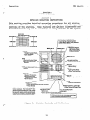
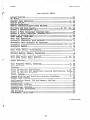
TABLE OF CONTENTS
CHAPTER
1 INTRODUCTION
. . ..*..................................
SECTION 1 GENERAL INFORMATION .............................
MANUAL SCOPE ...........................................
GENERAL DESCRIPTION ....................................
KEY SYSTEM FEATURES ....................................
SPECIFICATIONS ........................................
SECTION
1
1
:
2 INSTALLER/USER
RULES
INFORMATION
REGARDING FCC
AND REGULATIONS . . . . . . . . ..A...............
CHAPTER 2 INSTALLATION ......................................
...............................
MOUNTING.CONSIDERATIONS
CABLE ROUTING .........................................
CONNECTIONS ...........................................
CHECKOUT ..............................................
SYSTEM CLOCK INFORMATION ..............................
*.
CHAPTER 3 OPERATION .........................................
BASIC OPERATION ..........................................
FEATURES OPERATION .......................................
OPTIONAL FEATURES OPERATION ..............................
STATION OPERATING CONDITIONS .............................
SMDR AND COS PRINTOUT ....................................
15
11%
20
21
29
31
33
34
38
46
48
50
CHAPTER 4 SYSTEM PROGRAMMING ................................
GENERAL INFORMATION ...................................
BASE LEVEL PROGRAMMING
ENTRY ..........................
SYSTEM COS ............................................
LINE COS ..............................................
STATION COS ...........................................
53
53
53
54
59
61
CHAPTER
71
5 MAINTENANCE
SECTION
SECTION
CHAPTER
1 TECHNICAL ASSISTANCE
AND REPAIR SERVICE........7 1
2 TROUBLESHOOTING ................................
71
6 REPLACEMENT
PUBLICATION
. . . ..*......a...........................
PARTS . . . . . . . . . ..a.....................
INDEX . . . . . . ..***.......*...........*............
iv
76
77
.
IMI 66-031
Introduction
CHAPTER 1
INTRODUCTION
SECTION 1
GENERAL INFORMATION
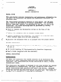
MANUAL SCOPE
This publication contains installation and maintenance information for
the Model 816 electronic key system and associated electronic key
telephone sets.
The installation procedures detailed in this manual, for the most
part, should be performed by a trained technician. The following
service items may, however, be performed by any user at his or her
discretion. All other servicing must be performed by factory
authorized personnel.
Place or replace any designation strips on the face of the
telephone.
Replace the telephone line or handset coiled cord.
Replace telephones and handsets. The handset is a special type.
Other handset types will not work properly.
Relocate the telephone when it is plugged into the proper system
jacks.
RELATED INFORMATION
l
IMI 01-001 Compliance Requirements To FCC Rules and Regulations Part
68 and 15
l
IMI 01-005 Handling Of Electrostatically Sensitive Components
l
User's Guide (supplied with the stations)
GENERAL DESCRIPTION
i
:
;c
;
The Model 816 electronic key system consists of an electronic Key
Service Unit (KSU), dedicated electronic key system telephone sets
(stations), and interconnecting wiring consisting of small, 4-wire,
twisted-pair cable.
This electronic key system is designed to not only provide the economy
and features of a conventional "lA2 type" system but also a much
easier installation made possible with small size wiring. Advanced
operating features are made possible by the electronic technology used
in the KSU and the dedicated key system telephone set. The system is
equipped for a maximum of 8 lines and 16 stations.
1
_
x-----------T---_,
_..__-._L__--_.
--- -__
z---
I
Introduction
IMI 66-031
:
L
The KSU is a fully electronic key service unit. It is essentially a
special purpose computer system acting as a communications controller
between TELCO or PABX supplied lines and propriatery 3-line and 8-line
telephone stations.
The KSU is contained in a functional, modern-style metal housing of
contemporary design in keeping with the needs-of the modern offlce
enviroment. .It is engineered to be wall or rack mounted.
-WThe telephone set is an electronic, microprocessor-controlled device.
It is desi ned to allow not only multiline pickup but also single key
access to 7eatures available from the serving TELCO or PABX switch.
All stations are equipped with standard modular jacks.
The telephone sets are available in 3-line (S-button) and 8-line
(lo-button) handsfree dialing models: 3-line and 8-line full
speakerphone models; and an B-line, handsfree dialing model with a
busy lamp field.
KEY SYSTEM
,
FEATURES
*
_.
-.
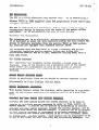
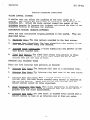
The electronic key telephone system provides a broad range of
features. Some of the features are a permanent part of the system
while others are programmable as part of the system or station
rogramming procedure. The following paragraphs describe the
Features.
&W&%4&8~~~~
Access to particular lines can be denied to certain stations in the
system through system programming. This access denied feature is
programmable on a per line/per station basis.
_.
4b@JGQ
Canferance
&4Ji!&&W
This system feature allows the stations, while operating in a private
mode, to add another station to an existing call or to a.multiline
call.
WW.WW&&MQ~
All-call and zone paging allows the system stations to be used to
receive or originate one-way messages in order to find, notify, or
summon someone.. A station can be enabled by-programming to receive
all-call and zone paging messages through the station speaker, and to
originate them using the station handset. A station can be programmed
to
only
receive messages‘or programmed to orignate messages as well.
The programming can enable zone paging in up to four different zones
or system-wide, all-call paging. Each station can be programmed to be
in any or all zones for both receiving and originating messages. The
2
-~
.
Introduction
c
IMI 66-031
system defaults to system-wide, all-call paging in zone D with all
stations having both receive and originate capability.
A station port can be programmed to interface with an external paging
amplifier. It can be dial accessed from the other stations in the
system. A line port can also be programmed to interface with an
external paging amplifier. This paging amplifier can be accessed from
the stations in the system with the line select key. DTMF tones can
be dialed through the line paging port to provide zone selection if
dialed zone selection is available at the external paging amplifier.
If an on-hold party hangs up at the TELCO/PBX end of the
communications link, causing an interruption in the tip/ring line
current, the system will drop the line off of the hold condition and
return it for service. The line select indicator will turn off to
indicate an idle line condition.
If the intercom line is selected while an outside line call is active,
this system feature will cause the outside call to be automatically
placed on hold.
A system feature provides automatic privacy on all lines at every
station. Automatic privacy prevents other stations from joining a
station on an active line unless that station user allows it. Through
programming, the system can be configured so that certain lines are .
normally non-private. When the non-private line is in use at a
particular station, users of other stations in the system can join
that station user on the non-private line. This can be accomplished
by pressing that line select key on their station.
An automatic redial of the last dialed number is available at every
station. A busy number or unanswered call is automatically redialed
by this feature. Once automatic redial is selected, the station will
select a line, automatically dial a number, and wait for a response.
It will do this once a minute for 10 minutes.
c
3
,
.
f
w
Introduction
IMI 66-031
';
f
,
L
The user must lift the handset to complete the call voice link.
Lifting the handset or pressing any other key will cancel further
automatic redial action. Users of the optional speakerphone station
can complete the call voice link by pressing the MONITOR OFF key
instead of lifting the handset.
X_/
The system will detect an A-lead contact closure on certain incoming
lines. When the system detects an A-lead contact Closure by an
external device connected to one of these lines, it causes a busy line
light indication for this line to appear at all the stations in the
system. This A-lead contact closure provides detection only. The
system does not send any A-lead signal to the external device
connected to the line. Pressing the line select key on a system
station cannot interrupt the external A-lead device unless the line is
programmed to be non-private.
Refer to the discussion titled G&&!J@?~&UU~&~
2&J&Q&&
The system provides basic, lA2 type features. Features such as
selective line pickup, common line, hold, and multiline pickup and
hold are available at every station.
'The system programming is electronically protected by a "super-cap"
device during an AC power failure. The stored program data will
remain in memory for a minimum of W-*:hours after AC power fails or is
Some key system models include a system clock. On
disconnected,
those models, the system clock will continue to run and keep time for
at least 30 minutes after an AC power failure or disconnect.
:
;
There is an optionally available 8-line telephone station equipped
with 14 visual indicators adjacent to the memory keys. This station
provides all of the available features in addition to a Busy Lamp
Field (BLF) display. The visual indicators of this station display
the status of the Direct Station Selection (DSS) intercom stations
provided by the system at the key locations.
-4
Introduction
IMI 66-031
The internal speaker at each station provides call-announce capability
over the intercom link. A handsfree response to a call-announce call
can be made. This response is transmitted by the microphone built into
the handset.
Call transfer allows incoming calls to be transferred from one station
to another, via the intercom link, in one of two ways. If both
stations have access to the incoming line, a common line pickup
transfer can be effected. If the other station does not have access
to the incoming line, transfer can still take place using the system
transfer feature. Some transfer considerations are as follows: If a
transfer is attempted when there is no call on hold, the station being
transferred to will receive the intercom dial tone, and the
transferring station will be dropped from the intercom line. If a
transfer is attempted and the station being transferred to does not
answer the intercom call, the transferring station will reconnect to
the call.
c
Contact points are available which provide relay contact closures
whenever an incoming line rings and whenever station 17 rings. The
contact closures track the ringing pattern and can be used to control
an external signalling device. When certain station ports are
prrogrammed to function as PA ports, these contact closures become
enable contacts. They close when the PA port is called and can be
used to enable an external PA system.
~11 class of service (COS) programming is performed from station 100
COS programming is used by the installer to configure and maintain the
system, line, and station operating conditions.
Class of service and toll restriction records can be received and
printed by any RS-232 compatible serial printer which is capable of
operating at 110/300 baud.
At initial power up of the system, the operating features are set to a
specific group of operating conditions (default conditions).
The
default conditions provide a complete operating system for use. It
can be left as a defaulted system or reprogrammed as desired. Default
conditions can be restored, if desired, by programming action.
5
Introduction
IMI 66-031
W.nsQ~&L~~
_
._
The system attendant station (station 10) can be called whenever the 0
key is dialed on the intercom line.
The ringing pattern of an incoming call follows the ringing pattern of
fhe TELCO or PBX system. The ringing pattern of a tone signalled
intercom call presents two tone bursts sounded every 4 seconds. A
voice signalled intercom sounds two tone bursts one time.
Any station can be set to a do-not-disturb mode with the MONITOR.
key. While in this mode, the station will not ring on any incoming
call nor will it accept an intercom call.
The DSS/BLF Console is an optional console device designed to be a
companion to a regular system station. It is useful with high call
volume systems which require a dedicated call transfer location. The
console provides 24ikey direct station selection (DSS) intercom and an
associated busy lamp field (BLF). It also provides one-key access to
system-wide! all-call paging. The console is designed to be connected
to any station port and serve as a companion to the station connected
to the adjacent data-line paired port. Installation of this option to
a system does not affect any features currently available to the
companion station.
duda-
4ikxaas
442su
&4&s&4 Ji$&2sa U8W
&?a&
A faceplate mounted volume control on each station can be adjusted to
set the audio level of the call announce speaker output, A bottom
mounted volume control on each station can be adjusted to set the
audio level of the tone ringer.
The system can accept DTMF tones from a station, send them through the
TELCO network, and hav.e them received at the distant end for inward
call completion at the distant system. This conventional, off-hook
dialing mode can be performed from every station in the system.
Pressing the HOLD key twice, when placing a call on hold, effects an
exclusive hold. condition. Exclusive hold links the held call to the
timed hold recall timeout feature. Exclusive hold prohibits the held
call from being picked up at any other station during the programmed
timeout period. After timeout, audible and visual signalling will
occur and the exclusive hold condition will revert to a normal line
hold condition.
6
.
Introduction
IMI-66-031
d
lgSSLvuithanskseLw
Each station comes equipped with a built-in direct station select
intercom for stations 12 through 25. Access to these stations is
effected by pressing the intercom select key and then pressing one of
the memory keys. This action completes a voice announced intercom
call to the selected station.
Any active outside line is
automatically placed on hold when the intercom select key is pressed.
When custom calling features are available via a .flash" signal, the
system can be programmed so that the RECALL key will generate a
"flash" signal when it is pressed. When custom calling features are
not available, the system can be programmed to allow the RECALL key to
act as a positive disconnect or dial tone recall key. These two
features are mutually exclusive. The system can be programmed to
provide only one of these features at a time.
Flexible ringing assignments are programmable on a per line/per
station basis. The system can be configured to provide direct ringing
for every line at every station; direct ringing for prime line with
delayed ringing for all other lines; and prime line ringing only.
Ringing can be disabled for each line on an individual basis at each
station. Subdued ringing is automatically provided to any station
that is busy on an outside line.
The station handset is compatible with magnetically-coupled
aids.
hearing
The light associated with the line select keys provide a visual
indication of the in-use and hold status of each line available for
use at a particular station.
Refer to the discussion titled, a
a
B&S
&JJJ&JJ~
J&J&-~,
’
Introduction
IMI 66-031
’
L
Should the intercom line be selected with no subsequent action taking
place, the system will timeout the active status and return the
station to an idle state.
Bach station is equipped with a last number redial feature. This
feature will save the last number manually dialed from the keypad. It
will redial the saved number upon key command. A newly dialed number
will automatically replace a currently saved number.
If a station is programmed to include a prime line, this line will be
automatically selected for a manual dialing operation when the handset
is taken off hook. If the prime line is busy, a manual line selection
must be made.
Auto dial and speed dial numbers can be programmed to include any
particular line desired. When this is done, an auto dial or speed
dial operation automatically selects that line for dialing. Should
(If a line is
that line be busy, manual line selection must be made.
selected manually for a speed dial call, either station or system,
press the HOLD key before pressing the speed dial key on the key pad.1
If a particular line is not programmed for selection as part of the
auto or speed dial, the prime line (if programmed) will be
automatically chosen. If the prime line is unavailable or busy, the
last line used to originate a call will be chosen.
Other than the prime line or the auto/speed dial line selection,
automatic preselection of a line is not part of the system. A line
can be manually selected before lifting the handset (for handsfree
dialing) or after the handset is lifted. The key pad is automatically
set for manual dialing when a manual line selection is made.
A key activated feature at each station will place a PBX or TELCO line
on hold and provide music-on-hold to the held party if that capability
is available.
Pressing the HOLD key once effects a normal timed hold condition. Any
station which has access to the line can pick up the held call. The
normal hold condition will hold a call for a programmed length of
time. At the end of the first timeout period, the line select
indicator will flutter rapidly at all stations and three quick tone
bursts will sound at the holding station. At the end of each
subsequent timeout period, the holding station receives an additional
three quick tone bursts.
8
.._J
IMI 66-031
mbsf(eus,SneedDialL
1
.-
‘
_
mixture of 3-line and 8-line telephone
can be standard, handsfree stations or full
‘.
ghen it is actuated. Th is
Itions with a programmed
lrammable.memory dialing features available
These memory keys can be programmed to
.c dialing purposes. The stored numbers can
lth and can include line or intercom
', pauses, and flash signals. A pause is
key is pressed, and a flash signal is stored
.s pressed. The pause and flash intervals
,tely, memory location 14 can provide
.ing of the last number dialed if a memory
tat location.
lmmed to provide 10 speed dial numbers at the
.umbers can be up to 150digits in length and
ntercom selection, numbers, Q'S, *'s,
ddition to the station speed dial numbers,
numbers are available at the keypad keys.
ers can be up to 31 digits in length, and
,mation as described above. %ystem speed
be done at station 10.
IMI 66-031
sting a non-electronic
. 2500.
This voice pair
thenever there is an AC
lg on this power failure
condition. The power
:t as soon as power is
iS
’
lower on indication and
I all other stations are
line unless that station
ws a station user to
ions can be added to an
ly interconnected by employing industry
and modular plug/jack combinations.
-conductor, twisted-pair cable throughout
tary contact, press and release types. They
11 monitoring, and other feature selection.
eature selection is provided by built-in
s)
l
llow one or more stations to access two
time resulting in a multipath conversation.
distant parties' stations is dependent upon
lines. If more than one internal station
8 the voice levels may be lower than when a
involved.
I
lection and a station
DSS memory key. When this
tomatically placed on hold
atically made to that
xtory.
This director
ial and station speed 3 ial
4sis to allow the stations
needed. Alternately, the
:one dialing.
9
I
L
Introduction
IMI 66-031
s
b
The system can be programmed on a per station basis to enable ringing
line preference. When ringing line preference is enabled at a
station, taking it off-hook will automatically connect it to an
outside line which has audible ringing. A line select key will not
have to be pressed.
This feature enables a key action to save the last number manual1
dialed from the keypad. The same key action will redial the save8
number when it is pressed at a later time. The saved number is
permanently available for later use until it is replaced with a new
number.
Each station can execute a self test when so enabled.
The optional speakerphone provides full handset free operation of all
features except voice signalled intercom calls. The handset must be
used for this purpose.
Refer to the discussion titled, &JJQ~
U&,&Q
Em
The SMDR feature allows a record of calls to be kept for each Station'
in the system. Call record data may be received and printed by any
RS-232 compatible, serial printer which is capable of operating at
110/300 baud. This feature records the number of the TELCO line used
and the digits dialed (up to 32 including up to 8 t's and *'s for
billing code information). These records are kept for all incoming
and outgoing calls greater than 20 seconds in length. In addition, on
incoming calls, the answer time (in tenths of a minute) for a ringing
line is kept. The call record is presented at an RS-232 level as
ASCII transmit data on terminals at the station connector block. The
call record is presented as it is taken. No mass storage of data is
maintained for later recall. Communications are one-way to the
printer only.
The system programming selects the timeout period for a call on hold.
When a held call exceeds the timeout period, the system audibly
signals the condition to the station that placed the call on hold. It
also visually signals all other stations. The audible signal is
repeated at the end of each time out period. The visual indication
continues until the held call is picked up.
12
I._
Introduction
IMI 66-031
,
System toll call restriction can be configured, by Class Of Service
programming, to prohibit some or all stations from calling a wide
range of number combinations.
The restricted numbers are specified on
programmable restricted number tables which are assigned on a per
station and per line basis.
In general, toll restriction works as follows: The programmable tables
of restricted numbers contain entries of up to 16 digits each. Each
table of restricted numbers can be programmed to be an "allowN table
or a "deny" table with entries in an "allow" table overriding entries
in a "deny" table. This feature allows exceptions to toll restriction
to be enabled. For example, the dialing of all 1-xxx-xxx-xxxx numbers
can be denied while the dialing of l-8000xxx-xxxx numbers is enabled.
A "match anything" symbol (t) can be stored to represent any digit
from 1 to 0. The programmed toll restriction tables are individually
assigned to each station and line.
When a line selection is made and a station is dialed, the system
examines the dialed number and makes a comparison between the station
toll restriction tables and the line toll restriction tables. Any
tables assigned to BOTH the station being used and the selected line
determine the toll restrictions to be imposed. Dialing a restricted
number on a restricted line from a restricted station will cause the
line to be automatically disconnected for 2 seconds.
The intercom feature links the stations of the system together. Four
intercon paths are available on the Model 816 system. Intercom calls
can be tone signalled or voice announced as desired, and can be
responded to in a handsfree manner. Intercom call progress is marked
by special tone signals. A visual indication is presented when all of
the paths are busy.
A special adapter is available which will allow a station to be
mounted on a wall.
zWU&&s
Refer to the discussion titled, m
snaaw
&j
&g
&Q&J
&T&
&J&&Q
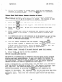
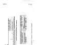
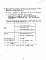
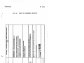
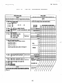
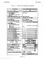
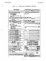
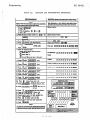
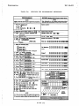
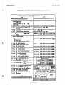
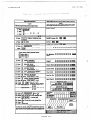
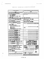
SPECIFICATIONS
The general specifications of the
shown in Table 1
Model 816 electronic key system are
13
:
.-.
_
IMI 66-031
Introduction
,
c
Table
1.
7)
General Specifications
Model
818
System System Capaclty Co Lines
Stations
Intercom Links
Paging Link
Power Dissipation KSU and power supply
fully loaded system
8
18
3
1
@ 117VAC nominal,
55 watts
Dimensions and Welghts KSU width (inches)
height
depth
KSU pounds
Keyset footprint (inches)
Keyset pounds (lb-ot)
15x!
E
23
7%x8%
2-10
Cable Requirements Station cable, P-pair twisted, non-shielded
Maximum cable length 1500 feet
A-Lead Control Loop Limits
Maximum Resistance of 1500 Ohms
24AWG
Power Requlrements KSU and power supply
Input: 117 VAC + 10% 0.4 AMPS, 80H2, single phase
Switching Principle Solid state space division analog switching
..
with stored program control.
Operating Environment Temperature: 32-120” F (O”-43.3”C)
Humidity 90% relative, noncondensing
Industry/Regulatory
Standards FCC certified, part 15a
FCC registered, part 88
UL Listed (in process)
EIA RS478, Bell Pub 48002 guidance
Hearing aid compatible
Termlnatlon for Outside Llnes Individual 623 -type four-conductor
Termination for Stations 25pair connector for connection
minijacks; USOC’s RJll C (or RJlPC with A/Al leads
for lines 7 or 8).
to external distribution
field.
Central Office Limits Maximum 1900 OHMS loop, minimum 15,000 OHMS cable insulation
CO/PBX Line Ringer Equivalence Number REN 0.3B
FCC Reglstratlon Number CVW7WC-12829-KF-E
Station Message Detail Recording (SMDR) Port Format: Serial, pseudo RS-232C (transmit only)
Parity: None
Data Bits: 7
Stop Bits: 2
Baud Rate: 300/l 10 COS programmable
Handshaking Requirements:
CTS (if available) from printer to KSU
RTS (if needed) from KSU to printer
Printer Cable Length: 50 feet maximum from KSU to printer
14
leakage.
--)
.._
Introduction
IMI 66-031
&
SECTION
2
INSTALLER/USER
INFORMATION
REGARDING FCC RULES AND REGULATIONS
This electronic key system complies with Federal Communications
Commission (FCC) Rules, Part 68.
The FCC registration label on the KSU contains the FCC registration
number, the ringer equivalence number, the model number, and the
serial number or production date of the system.
NOTIFICATION
TO TELEPHONE
COMPANY
Unless the telephone operating company provides and installs the
system, the telephone operating company must be notified before a
connection is made. The lines (telephone numbers) involved, the FCC
registration number, and the ringer equivalence must be provided to
the telephone company. The FCC registration number and the ringer
equivalence number of this equipment are provided on the label
attached to the KSU.
The user is required to notify the telephone company when final
disconnection of this equipment from the telephone company line
occurs.
COMPATIBILITY
WITH
TELEPHONE
NETWORK
When necessary, the telephone operating company provides information
on the maximum number of telephones or ringers that can be connected
to one line, as well as any other applicable technical information.
The telephone operating company can temporarily discontinue service .
and make changes which could effect the operation of your equipment*
They must,
however, provide adequate notice, in writing, of any future
equipment changes that would make the system incompatible.
INSTALLATION REQUIREMENTS
Connection of the electronic key system to the telephone lines must be
through universal service order code (USOC) outlet jacks supplied by
the telephone operating company. If the installation site does not
have the proper outlets, ask the telephone company business office to
install new outlets or adapters for the present ones. The correct
outlet jacks for this system are type RJllC or RJ12C jacks.
15
_
IMI 66-031
Introduction
;
.
PARTY LINES AND COIN LINES
Local telephone company regulations may not permit connections to
party lines and coin lines by anyone except the telephone operating
company.
TROUBLESHOOTING
If a service problem occurs, first try to determine if the trouble is
in the on-site system or in the telephone company equipment.
Disconnect all equipment not owned by the telephone company. If this
to
corrects the problem, the faulty equipment must not be reconnected
the telephone line until the problem has been corrected.
Any trouble
that causes improper operation of the telephone network may require
the telephone company to discontinue service to the trouble site after
they notify the user of the reason.
i
REPAIR AUTHORIZATION
.
..
FCC regulations do not permit repair of customer owned equipment b
anyone except the manufacturer or their authorized agent and by otX ers
who might be authorized by the FCC. However, routine repairs can be
made according to the maintenance instructions in this publication,
provided that all FCC restrictions are obeyed.
RADIO FREQUENCY INTERFERENCE
--I
The electronic key system contains incidental radio frequency
generating circuitry and, if not installed and used properly, may
cause interference to radio and television reception.
This equipment
has.been tested and found to comply with the limits for a Class A
computing device pursuant to Subpart J of Part 15 of FCC Rules. These
limits are designed to provide reasonable protection against such
interference when operated in a commercial environment.
..,
Operation of this equipment in a residential area may cause
interference to radio and television reception; in which case the user
is encouraged to take whatever measures may be required to correct the
interference.
..
If this equipment does cause interference to radio or television
reception, which can be determined by turning the equipment off andon, the user is encouraged to try to correct the interference by one
or both of the following measures: Reorient the television or radio
receiving antenna. Relocate the KSU, the individual telephone
stations, and the radio or TV with respect to each other.
..
16
IMI 66-031
Introduction
r.
If necessary, the user should consult the manufacturer or an
experienced radio/television technician for additional Suggestions.
The user may find the following booklet prepared by the Federal
Communications Commission helpful: "HOW to Identify and Resolve
Radio-TV Interference Problems." This booklet is available from the
Government Printing Office, Washington D.C. 20402. Stock No.
004-000-00345-4.
RINGER EQUIVALENCE NUMBER
The REN of each line of the KSU is 0.3s. The FCC requires the
installer to determine the total REN for each line, and record it at
the equipment.
17-18
Installation
IMI 66-031
*
CHAPTER 2
INSTALLATION
.,f
MOUNTING
0
CONSIDERATIONS
The KSU cabinet should be attached vertically to any sturdy, flat,
surface. It may be vertically rack mounted if desired. It must be
located within 6 feet of a properly grounded, three-wire, 117VAC,
electrical outlet. The distance between the KSU and the TELCO/PBX
jacks must be 25 feet or less as per FCC requirements. A nominal
distance of 7 feet is recommended.
a Choose a secure, dry mounting location with adequate ventilation.
The temperature range of the location must be within 32-120 degrees
F (O-49 degrees C). If the mounting surface is damp or if it is
concrete or masonry material, a backboard must be attached to the
mounting surface to be used for KSU mounting. Suitable mounting
backboards are available commercially or can be constructed out of
l/2-inch plywood cut to size.
l
c-
Tools and hardware required for mounting the KSU cabinet include:
l/4 x l-inch round head wood screws, toggle bolts, or wall anchors
and fasteners; a screwdriver; an electric drill if prepared holes
are required; and a connecting tool for fastening wires to a type-66
connector block.
1.
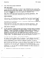
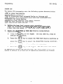
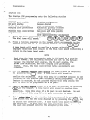
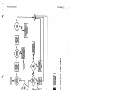
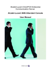
A full scale mounting template is
Hold'or tape this template to the
location of the mounting holes on
located on the template. The KSU
on Figure 1.
2.
Drill holes in the mounting surface of a proper size to
accommodate the hardware being used. If necessary, prepare these
holes with inserts, anchors or other attachment devices as
dictated by the type of mounting surface.
3.
Attach the KSU to the mounting surface with four (4) screws
installed through the KSU mounting flange and into the mounting
surface holes. Note that the flange holes are elongated with an
enlargement at one end of the hole. This feature allows the
mounting screws to be partially installed in the mounting surface
before the KSU is hung on them.
19
supplied in the KSU packing box.
mounting surface, and mark the
the mounting surface as they are
mounting dimensions are as shown
.
.
IMI 66-031
Installation
;
_
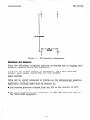
19.25 INCHES
hNElEr----i
o-al
I
Figure 1.
KSU Mounting Dimensions
W&&Wi%&&&Qtina
Place the individual telephone stations as desired and in keeping with
accepted industry and office standards.
A station can be wall mounted if necessary. Use a wall mounting
bracket (part number 701032-056) for this purpose.
CABLE ROUTING
Cable may be routed concealed or visible as the installation location
requires. Good engineering practices must be observed and all
applicable building codes must be adhered to.
l
The maximum distance allowed from the KSU to the station is 1500
feet using t24 gauge, twisted-pair cable.
a The allowed tip/ring loop resistance is 1900 ohms from the jack to
the TELCO/PABX equipment.
20
s
IMI
Installation
66-031
’ L
f-
c
CONNECTIONS
Connection between the KSU and the TELCO or PABX line is via four-wire
cable and modular plug/jack connection. The maximum length of a line
cable is determined by the limitations detailed above.
A-Lead Control
The KSU inputs of TELCO lines 7 and 8 are configured to detect an
A-lead (A and Al) control signal when it is applied at the modular
line jack of the KSU. When the KSU detects an A-lead control signal
on line 7 or 8, it causes a busy line light indication to be shown at
all of the key system stations connected to it. The A-lead loop
resistance must not exceed 1500 ohms.
A typical use of A-lead control signal detection would find a
single-line, non-key system, telephone set, modem, data terminal, etc.
configured for A-lead control and connected to the TELCO line at
terminal clips provided on the station connector block connected to J2
of the KSU. A connected device parallels the tip and ring leads of
the TELCO line and supplies the A and Al control signals to the KSU.
&&z&&Q
(
$&W&&z@
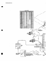
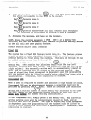
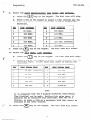
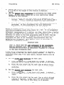
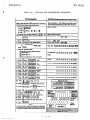
Connections between the KSU and the stations are typically via two
66M-xx station distribution connector blocks per the discussion steps
given below. Refer to Figures 2 through 5 for connection details.
Various tvnes of station distribution connector blocks are available
and may be-used in lieu of the type 66M-xx connector if desired.
NOTE
The system provides one tip and ring pair connected to line
1 as an emergency, power failure circuit. This power
failure pair is located as detailed on Figures 4 and 5. The
power failure pair is only active during a power failure.
An industry standard, single-line telephone, such as a type
2500, can be connected to this pair and used to provide
communications capability should the AC power to the system
be interrupted.
i.
Connect a cable between the KSU connector and the connector on the
66~-xx
connecting block.
2.
Connect four-wire, twisted-pair cables from-the 66M-XX block
directly to the station or from the 66M-xx block to modular RJ14
configuration station jacks.
21
_
Installation
IMI 66-031
The polarity between the individual wires in a particular
voice or data pair is not critical; however, do not connect
the voice circuits to the data circuits: To do SOI will
make a station inoperative as well as the adjacent odd or
even station.
3.
After making the wiring connections discussed above and
illustrated in Figures 2 through 5, double check all connections
and cable routing to insure accuracy.
When a serial data printer is used for SMDR and COS printout, connect
it to clips 41, 42 43, and 44 of station connector block Jl.
Transmitted data, signal ground, request-to-send, and clear-to-send
terminations are supplied at the connection block by the KSU. Signal
levels meet RS-232 specifications. A typical connection configuration
is as illustrated in Figure 5. The maximum distance between the
printer and the KSU must not exceed 50 feet. When preparing a cable
for connection to the printer interface connector, refer to the
manufacturer's manual applicable to the printer being interfaced, and
make the following wiring connections:
l
Wire the TD line (data to printer from KSU - clip 41) to the printer
receive data input pin.
-
0
Wire the SG line (signal ground - clip 42) to the printer signal
ground pin.'
l
Wire the RTS line (status signal from the KSU to the printer - clip
43) to the printer data-set-ready input pin.
a Wire the CTS line (status from printer to KSU - clip 44) to the
printer request-to-send output pin.
Configure the printer , per the manufacturer's instructions, to receive
7-bit data, 2 stop bits, and no parity. Set the baud rate for the
serial data at 110 or 300 baud. The printer baud rate setting must
match the system baud rate set by COS programming. The system
defaults to a baud rate of 110.
22
.
-.,
_-__
__-.__-_-~___
Installation
IMI 66-031
I
To apply AC power to the KSU, connect the AC power cord to a properly
grounded, three-wire, 117VAC electrical outlet. A plug-in, power line
surge protector should be installed between the KSU power cord and the
AC outlet.
Do not connect the AC power cord until the installation has
been checked per the instructions given later .in this
chapter.
It is recommended that a grounding wire, separate from the three wire
AC line cord, be used. Some local codes may require this use- A
ground stud is located at the lower right corner of the KSU for this
purpose. Wire a 810 or #12, insulated, solid copper wire between this
ground stud and a reliable earth ground such as a metal cold water
pipe or a building frame ground.
c
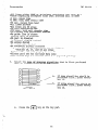
mo sets of relay closure contact points, are available at the Jl
station connector block. One set (clips 45 and 46) provides a relay
contact closure whenever any of the TELCO lines, connected to the KSU,
ring. The other set (clips 47 and 48) provides a relay contact
closure whenever station 17 rings. These contact closures track the
ringing pattern in both cases. The contacts are closed during the
ring on period and are open during the silent period.
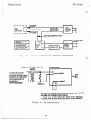
A typical connection to these terminals is illustrated in Figure 2.
Refer to the paragraph headed -3
~~JJJJJ &.J+Q&~~
for a discussion
for using these terminals in this alternate paging function.
m
Do not exceed a 0.4 amps at 24 volts load on these control
terminals. If the load requirements exceed this limit,
connect the load through an external relay. DO NOT CONNECT
THESE CONTROL TERMINALS DIRECTLY TO THE 117VAC LINE.
’
i.
Installation
4
2
;
%?Etews
IMI 66-031
.+
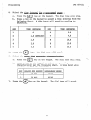
can be programmed to be a PA station port
e!+w
IaLii
e ephone
station port (see Chapter 4 for programming
details). When this is done, the audio input of a PA amplifier can be
connected to the audio pair of the station port as illustrated in
Figure 3. The connection must be isolated with a 600 ohm to 600 ohm
audio matching transformer. Terminate the audio input of the PA
amplifier with a 620 ohm (nominal value) resistor.
the Common Audible contact
@-=JQa;M&~~~a~*
Points are automatica y recon lgure as PA enable terminals. The
on these terminals
occurs when PA station 23
relay contact closure
is dialed. The normal common audible function, as discussed
previously, is disabled as long as station 23 is a PA station.
l
'!F
&$ &&&J
a & m
e a a u~ga
the Auxiliary Station
Interface (station 17 audible) contact points are automatically
reconfigured as PA enable terminals. The relay contact closure on
these terminals occurs when PA station 25 is dialed. The normal
auxiliary station interface, as discussed previously, is disabled-as
long as station 25 is a PA station.
A line port can be configured by class-of service programming to be -an
AUXILIARY port. As an AUXILIARY port, it can be used to couple a.
statlon voice path to an external device. This is done from any
allowed station by pressing the proper line select key to select the
AUXILIARY port. DTMF tones or dial pulses can be sent through the
auxiliary port as needed.
,'\
If direct access area paging is to be part of the system, connect the'
audio input of a paging amplifier to the KSU line jack programmed to
be an AUXILIARY port. The input impedance of this port is
a proximately 600 ohms. The connection must be isolated with a 600
oRm to 600 ohm audio matching transformer. Terminate the audio input
of the paging amplifier with a 620 ohm (nominal value) resistor. A
tone select, zone-paging amplifier can be employed if desired. If
used, the zone-select code must be dialed after the AUXILIARY port
line select key is pressed.
If music on hold is to be part of the system, connect a KX registered
music source to the KSU input jack (phono jack) provided for this
purpose. The impedance of this input is approximately 500 ohms.
Level adjustment of the music source may be necessary. This may be
done during system checkout.
e
:;-
.'
24
Installation
IMI 66-031
An optional station is available which is equipped with a 14 station
Busy Lamp Field (BLF). up to eight BLF stations can be connected to
the system. A BLF station can be connected to any odd or even station
port in the system per the following guidelines.
l The installed distance between the KSU and the BLF station must be
limited to 1000 feet or less.
OThe data-line paired station port cannot be used as a BLF station
connection or as a regular station connection. Data-line pairing
is: 10-11, 12-13, 14-15, 16-17, 18-19, 19-21, 22-24, and 23-25.
l The overload paired station port cannot be used as a BLF station
connection but can be used as a regular station connection.
Overload pairing is: 10-12, 11-13, 14-16, 15-17, 18-20, 19-21,
22-24, and 23-25.
l A port, paired in either manner with a BLF station, can be used as a
PA port if desired.
r
The optional DSS/BLF console may be installed at any station port to
work in conjunction with a companion system station connected to the
adjacent port (e.g.; port 10 for station and port 11 for console).
The installed distance limit between the KSU and the console is the
same as that specified for the companion station. Connect all four
wires (voice pair and data pair) of the console cable to the station
connection block.
The voice pair connections of the console can be used simultaneously
to enable a PA port function. Refer to the paragraph in this chapter
headed Q&Q &SW
m&
J&&MS
w&*
and to the illustration shown
in Figure 5. Per that discussion, wire a PA amplifier input to the
DSS/BLF console voice-pair at the station connector block clip
terminals. Use an audio matching transformer, as discussed in the
referenced paragraph and illustration, to provide isolation. If an
enable signal is required with the particular PA equipment being used,
the console and PA equipment connections are limited to the station
ports specified in the above mentioned reference.
The DSS/BLF console port must be programmed as a DSS/BLF port (see
Chapter 4 for programming details) before console operation can take
place. The console port must be also programmed as a PA port if a PA
amplifier has been.connected to the voice pair as part of the system.
25
I
IMI 66-031
Installation
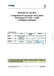
CLIP TERM
l----1
24V@
0.4A MAX
VOLTAGE CLAMPING DIODE
RECOMMENDED
CONTACT CLOSURE
External Signalling --Typical Connection
Figure 2.
600-h
TO KSU STATION
TO 6OOA
(1:l)
PA SYSTEM
AUDIO
TRANSFOF
111 r
PORT 23 OR 25 IF
ENABLE IS REQUIRED
OR TO ANY UNUSED
STATION PORT IF
ENABLE IS
NOT REQUIRED.
I
AUDIO INPUT
:
.
.
ENABLE INPUT
t
TO KSU EXTERNAL
CONTROL CONNECTION
POINTS
ON 66M-XX CONNECTOR
BLOCK.
l
CLIPS 45 & 46 FOR STATION PORT 23 PA ENABLE
l
CLIPS 47 8148 FOR STATION PORT 25 PA ENABLE
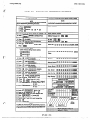
Figure 3.
PA Connections
26
_..__..___
Installation
IMI
Figure
4.
System
Interconnection-Typical
Connections
27
66-031
Installation
IMI
GREEN-WHITE
1
J
1
3
1
12
13
I
RED-SLATE
SLATE-RED
E
1
1
l4
-_c._..
.
I
~~
111
1 z
-I
BLACK-BROWN
BROWN-BLACK
YELLOW-BLUE
BLUE-YELLOW
YELLOW-ORANGE
ORANGE-YELLOW/
YELLOW-GREEN
GREEN-YELLOW
YELLOW-BROWN
BROWN-YELLOW
YELLOW-SLATE
SLATE-YELLOW
VIOLET-BLUE
15
41
I6
,~
”
.n
I
PA’R
DATA
PAIR
I
VOICE
1
I
j-1
’
1
1
1 ‘= 1
’
1
DAIE)
I
-I ,
43
18
44
,q /
~
1L
DATA
PAIR
I
I
a”
21
22
23
1 GREEN
r RED
YELLOW
BLACK
SEEN
24
25
SPAREI------+
-
DATA
PAIR
19
__
/ ;i 1
1RED
GREEN
35
36
37
YELLOW
BLACK
GREEN
--...
SPARE
FROM
SMDR
TELCO
LINE 7
23
VIOLET-BROWN
SLATE-VIOLET
VIOLET-SLATE
VOICE
PAIR
VOICE
19
VIOLET-ORANGE
BROWN-VIOLET
r)c
&J
“?%tE( SPARE 1
BLUE-VIOLET
ORANGE-VIOLET
VIOLET-GREEN
GREEN-VIOLET
1
1
17
1
‘*
VOICE
1
-j 16
,4
1
24
25
40
23
COMM.
49
AUDlt
&A17
24
25
50
Figure
.
3.
CONTACT
CONTACT
FnnU
. .._...
TELCO
CONTACT
CONTACT
AUDIB.
POWER
TIP
FAIL
RING
5.
1
KSU
LINE
.
SPARE
To Station
28
8
TIP
I
1 GREEN
I
I
45
46
RING
RED
A
Al
YELLOW
47
BLACK
46
-
GREEN
49
m
Wiring
66-031
.
Installation
IMI 66-031
..
CHECKOUT
The system operating features are set to the system default conditions
at initial power up. These conditions provide a basic operating
system. They can be altered as described in the Chapter 4 Class Of
Service programming discussion; however, the system
should
be
initially checked out with the default conditions in place.
The system default conditions are as follows.
-All lines are DTMF
-Voice signalling attempted first when intercom call is made
-1 sec. pause time
-2 sec. dial tone recall time
-30 sec. recall from hold
-All lines private
-All lines are CO lines
-300 msec. held call abandon time
-No ringing line preference enabled
-No prime line is chosen
-DSS/BLF port is disabled
-PA port is disabled
-No delayed ringing enabled
-No access denied
-No origination denied
-No automatic privacy released
-Day and night ringing patterns set as follows:
-station 10, 17, and 24 all lines
-System-wide, all call paging in zone D
-SMDR port set for 110 baud data rate
pairing)
-Line select buttons l-n selects lines l-n (squared
Whenever the system is operating, default conditions can be reset from
station 10 per the following instructions.
0
1.
Press the
2.
Press the following keys @maa@@@@
3.
Press the
ITCM
button.
button.
0
the KSU and telephone
MONITOR
Check
installation for proper operation by
performing the following actions.
1.
Before any AC power is applied to the system, measure the
resistance across each station voice and data pair. Disconnect
the 250pair cables from the KSU at the 66M-xx connector blocks but
leave the stations connected. Make the measurements from the
blocks (refer to Figures 4 and 5 to identify the connection points
of the voice and data pairs). The measured resistance must be as
follows:
29
.
.
Installation
IMI 66-031
VOICE PAIR: 45 OHMS TYPICAL (40 OHMS MIN.--150 OHMS MAX.)
DATA PAIR: 45 OHMS TYPICAL (40 OHMS MIN.--150 OHMS MAX.)
,
.?
Readings which are outside of the above range indicate a
possible wiring or station problem.
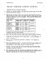
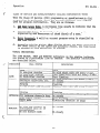
2.
Connect the 250pair cables, and plug the AC power plug of the KSU
into the electrical outlet.
3.
Measure the voltage across one voice line and one data line and
then across the other voice line and the other data line for each
even and odd station. Make the measurements at the 66M-xx blocks
(refer to Figures 4 and 5 as needed). The measured voltage must
be as follows:
-1
each odd sta.
I
I
I
Readings other than those shown above indicate a
possible wiring or KSU problem.
4.
Check the red light emitting diode (LED) system status indicator.
Be sure that it is on steady. If it is off or flashing,
disconnect and reconnect the AC power plug. If the indicator is
still not on steady, refer to the Failure Analysis Flow Chart
.
found in Chapter 5.
5.
Refer to the information provided in Chapter 3 for operating
information.
6.
From each telephone station, initiate and receive an outside line
and an intercom line call. Be sure to set the ringer volume to
the medimum or high volume setting at each station.
7.
Exercise every feature and option available at each individual
station. Be sure that the line select indicators and any other
indicators function properly.
8.
Once the basic system is 'verified as completely operational, set
the system clock per the instructions given below. Then, refer to
Chapter 4 and perform the Class Of Service programming.
30
Installation
SYSTEM
IMI 66-031
CLOCK
INFORMATION
2
sisidaaaa
From station 10, set the system clock to the current time.as follows:
0ITCM
1.
Press
2.
Dial the clock date with the key pad keys
00
YEAR
, then dial
00
MONTH
00DAY
0000
HOUR
MINUTE
NOTE
Values less than 10 must be dialed as OX, and hours must be
expressed in the 240hour format.
3.
If the SMDR printer is installed and operating, the clock date
will be printed as illustrated in the following typical example.
** 01/08/86 16:00
4.
Reset the minutes setting, if necessary, as follows:
a.
Repeat step 1.
b.
Dial the new setting digits, and press the
C.
A new clock date printing will occur.
0#p
key.
Obtain a printing of the current clock date whenever needed:
At station 10, press
0
ITCM
and dial@a(#
A clock date printing will occur automatically once each 24-hour
period. This daily, automatic printing will be:
** MO/DY/YR 0O:OO
(current date and 0O:OO hours)
31
;
IMI 66-031
Installation
,
The system clock will continue to run for at least 30 minutes after AC
power has been removed form the system. If power is restored within
the 30-minute backup period, the following printing sequence will
occur:
OFF TIME
** MO/DY/YR HR:MN
(time of power outage)
** MO/DY/YR HR:MN
(time of power return)
If power is not restored within the backup period, the following
printing sequence will occur when the power is restored.
CLOCK NOT VALID!
** 12/01/86 OO:OO(
(default clock date)
The clock will begin running from the default date.
to the current date per the instructions above.
It must be reset
.-
.
32
IMI
Operation
66-031
_
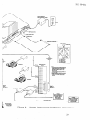
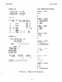
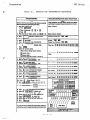
CHAPTER 3
SYSTEM OPERATION
/
SECTION 1
DETAILED OPERATING INSTRUCTIONS
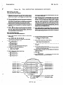
This section
provides
detailed
operating
procedures
for all station
features.
The illustration
shown in Figure 6 points out the operating
Some features
and options
illustrated
and
controls
of the stations.
described
herein may not be available
on every station
in the system.
FIXED DSS
STATION SELECTOR
LOCATIONS
00
&--
STATION 12
2
1
THROUGH
I
00
00
00
00
00
00
STATION
IQ
MEMORY DIALING FEATURES
l Auto Dialing of Special Number
l Direct Station Select (DSS) Intercom
l Feature Code Dialing
1
THROUGH
I
STATION 25
STATION 18
MEMORY
RECALL
l Transfer Access (Flash)
l Dial Tone Recall
l Call Transfer
KEY #l
YEMORV
I
KEY #
AUTO REDIAL
l Repeatedly Redials
Last Number Dialed
(Unless programmed as
*n autodial location)
EMORY KEY 114
SAVE
l Save Last Number Dialed
l Store Auto/Speed
Dial
Numbers
OLUME CONTROL
l Adjusts Voice Volume
MUTE
l Prevent distant party fro
l
l
l
l
l
Speaker Off (Monitor)
End Handsfree Call
(Speakerphone Model)
Do Not Disturb
Last Number Redial
Pulse/Tone Switching
System Speed Dial Enable
Intercom Line Selector
n and Key Pad Functions
RINGER CONTROL (ON BASE)
l Adjust Volume of Ringer Tone
A 5-key telephone
trative purposes
phone set is also a
for use with syste
line capacity. Both 5-key and lo-key configurations are available as handsfree dialing
models and as full speakerphone models.
Figure 6.
LINE SELECTORS
l Select Line
l Enable Conferencing
l Enable Speaker For On-Hook Dialing
OUT DIRECTORY
NOTE: Um rM
keys m numbered lrom WI to tQhL Key 41 b nexi
tobeHOLD key. K~ys4lhrough 8 (whmmU.bie)oecup),.,,uppr
“WI 4 b.kW MA.4 dlm(ly ,b”. th. HOLD k.y.
Station Controls and Indicators
33
ss
IMI 66-031.
Operation
.
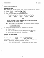
BASIC OPERATION
ORIGINATE A CALL (OUTSIDE LINE)
Press an unlighted line select key. When the dial tone is heard, dial
the desired number. The line select indicator will wink Slowly at the
calling station and be on steady at all other stations when the line
select key is pressed. The station speaker will sound the dial tone
and the ring back or busv tone sicrnals. If the calling station is not
a speakerphone, the user-must lifi the handset to compiete the call
when the called party answers. If a busy tone is received or no
key to end the call.
answer is heard, the user must press the *tDN,TOR
0
ANSWER A CALL (OUTSIDX LINE)
Press the line select key with the flashing indicator, and lift the
handset. The indicator changes from flashing to a wink off at the
calling station and to a steady bright at all other stations.
MANUAL HOLD
kUdAcallUU&W&
SHIFT
0HoLD-
key. The call
the outside party to wait, and press the
a21 stations.
the
indicator
changes
to
winking
at
goes on hoiflFTnd
soon the
key is pressed, the user can hang up or use any
Ask
As
0
available telephone
HOLD
function. To return to the held party, press the
line select key. Refer to the paragraph headed Q&,& i$.JwmB
for
a
discussion on transferring a held call.
If a held party hangs up, the key system will: wait a programmed
period of time, automatically return the holding station to an idle
condition, and turn off the line select indicator. This feature is
contingent upon the availability of a loop disconnect feature in the
TELCO/PBX equipment.
If the key system is so programmed, the line select indicator will
flutter rapidly at all stations and three quick tones bursts will
sound at the holding station when someone has been on hold beyond a
predetermined time. The holding station will periodically sound the
three quick tone bursts as long as the call remains on hold.
SHIFT
If the
0
HOLD
key is pressed twice and no other stations are connected
to the same line, an exclusive hold condition is activated. The line
Select indicator will be on steady at all other stations and will wink
off at the calling station. An exclusive hold will prevent any other
station from accessing the held line. Should a recall from hold
occur, the exclusive hold condition will revert to a standard hold
34
'7
.
_
IMI 66-031
Operation
.-
condition allowing any other station to access the line.
Press the ITCM
key. The intercom dial tone will sound, and the
intercom in
SJ lcator of the calling station will wink slowlY.
2.
Dial the intercom number of the desired station. If the handset
is off-hook, press the ITCM key again. This action places the
0
called station in a tone signalling mode. A double ringing tone
burst, repeated every 4 seconds, will be heard at the station
being called. Two bursts of a ring back tone will be heard at
your station every 4 seconds.
3.
If handset on the calling station is on-hook when the called party
answers, it must be lifted to complete the conversation link.
4.
If the called station is busy on another intercom call, the system
will return a busy tone. If the called station is busy on an
outside call, the system will return a fast ring back tone. The
caller may wait for the called party to answer or disconnect by
pressing the
When the ringing tone sounds, the user must lift the handset to answer
the call. If currently engaged in a call on an outside line, the user
may disconnect from it by pressing the hookswitch, or place it on hold
by pressing the
key when the flashing intercom indicator is
observed.
,TCM
0
ITCM
1.
Lift the handset (even when using a speakerphone), press the
.U
and listen for the dial tone. Dial the intercom number of
key,
the desired station.
2.
The calling station will sound a single tone burst to let the user
know that the voice signalling mode is active. They can speak
their message after hearing this confirming tone.
3.
If the called station is busy on an outside call, the system will
revert to a tone signalling mode and the calling station will
receive a fast ring back tone.
4.
If the called station is busy on an intercom call, the calling
station receive a busy tone.
Ansble&W B JiQbx $ii!!bama
L.
;68tr?rcom iaL&
A user can respond to a single tone burst followed by a caller's voice
without lifting the handset. They need only to speak toward the
35
:
Operation
IMI 66-031
telephone in a normal tone of voice. A two way conversation may
continue in this handsfree manner or the user can lift the handset for
a private conversation.
CALL TRANSFER
If the incoming line is common to the calling station and to the
station to which a transfer is to be made, a common line
pick
UP
transfer can be effected by the station user. To do so, proceed as
follows:
key.
0lTCM
1.
While the call is active, press the
automatically places the call on hold.
2.
Make an intercom call to the station to which a transfer is
desired, announce the call, identify the line, and hang up.
3.
That station user must press the line select key of the called
station to pick up the call.
This action
If the called station does not have direct access to the active line
to receive a transferred call, follow the procedure detailed below to
transfer a call.
0
1.
While the call is active, press the ITCM
key. This action
automatically places the call on hold. Use the intercom to
contact the station to which the transfer is directed.
2.
The user 'of the called station must lift the handset to accept a
transferred call. Once the called station is ready to receive the
call, the caller must press the RECALLkey on the calling station.
The transfer will take place.
0
3.
If the called station does not answer, the caller can press the
RECALL key on the calling station to return to the held party. If
the called party declines the call, they must hang up. The caller
can then press the RECALLkey to return to the held party.
MULTILINE CONFERENCING
0
The key system will allow one telephone set to access two outside
lines at the same time. The resulting three-way conversation is
referred to as multiline conferencing. When using this conferencing
feature, it should be noted that under certain line conditions
transmission levels may not be adequate. To enable multiline
conferencing, the station user must perform the following procedure.
1.
Answer or make a call, and place it on hold.
2.
Select an idle line, and make a second call.
36
:
Operation
IMI 66-031
Establish the conference per the following steps:
a.
Press and hold the line select key of the second call.
b.
Press the line select key of the first call.
C.
Release both line select keys.
Both lines are now connected to the same station in a conference call.
4.
The user can selectively disconnect one member of the conference
call while saving the other by pressing the line select key of the
line to be saved. The other line will automatically be
disconnected.
5.
The user may hold conferenced lines and use other telephone
features. The conference call can be re-established per step 3,
above.
6.
Other stations may be added to the conference call by placing the
conferenced line on hold and then releasing privacy. Refer to the
paragraph titled m
m
mu
&$,&&Jja for details.
7,
End the conference call by hanging up.
AUTOMATIC PRIVACY
A station can be programmed to operate in a normally private or a
feature can be programmed on a per line basis.
non-private mode. This
The system manager determines station features.
The private mode, when programmed, allows exclusive use of an active.
line. NO other station can connect to an active line unless the
add-on conferencing feature described below is used.
In the non-private mode, when it is programmed, several stations in
the system can connect to a line at one time. When a station is
connected to a line, other stations can also connect to it. Another
station user may connect to a line by pressing the line select key on
their station. The resulting conference is referred to as common line
pick up.
37
IMI 66-031
Operation
i
ADD-ON CONFERENCE/PRIVACY
RELEASE
',
.
Once a station connects to a line in a private mode, all other
stations are excluded from connecting to it. A user can add other
stations to that line as follows:
1.
Place the call on hold, and use the intercom feature to invite an
additional station to join the line.
2.
Press and hold the line select key on the first station. This
makes the line non-secure. The user of the second station must
press the same line select key to join the line.
3.
Release the line select key after the other station has joined the
conversation to return the line to a private condition for both
stations.
:
FEATURES OPERATION
LAST NUMBER REDIAL
A station is equipped with a last number redial feature, it may be
used to repeat the last number manually dialed from the dial pad. A
station user may employ the feature as follows:
1.
0#B
key. The station will automatically turn on the
Press the
monitor speaker, select the station prime line, if available, or
the last active line, and will dial the last number (up to 31
digits) that was dialed from the keypad.
NOTE
The keypad always exists, at idle, as an automatic line
select speed dialer. If a line select key is pressed to
select a line, the station converts the keypad to a manual
dialing mode. Therefore, to avoid the need to manually dial
a number after manually selecting a line, the user must
SHIFT
convert the keypad back into a speed dialer by pressing the
HOLD
key.
0
2.
Listen for an answer or a busy tone.
complete an answered call.
busy or unanswered call.
up the handset to
key to terminate a
SAVED NUMBER REDIAL
0
The %VE
key can be used to store the last number manually dialed
from the keypad. After the number is dialed and before any other
numbers are dialed, the user can press the m
key to cause the
last manually dialed number to be stored for later recall. This
number remains stored until replaced by another one. This action can
be taken while the station is either on-hook or off-hook. To dial
using the saved last number feature, the user must do as follows:
38
-7
Operation
.I
IMI 66-031
SHIFT
0
0
Press the HoLD key and immediately press the SAVE key.
The station will automatically turn on the monitor speaker: select
the station prime line, if available, or the last active line; and
dial the saved number.
2.
Listen for an answer or a busy tone. Pick up the handset to
complete an answered call. Press the MONITOR key to terminate a
busy or unanswered call.
0
AUTOMATIC REDIAL (OF BUSY NUMBERS)
An automatic redial of a busy number can be performed by a station
user.
This feature is available when the station is connected to a
line and a dialing operation has taken place resulting in a busy
signal or no answer. Automatic redial is automatically disabled
whenever a memory dialing.feature is programmed at memory key 14 but
is automatically restored when the programmed feature is cleared.
To use the automatic redial feature, proceed as follows:
1.
When the busy number signal is heard , press the memory key 14
(AUTO REDIAL). Hang up the handset if off hook. The
light
0
ITCM
will flash rapidly to indicate that automatic redial is active.
r
2.
After a 1 minute wait, the system will activate the station
monitor speaker, reselect the line, and redial the number. If the
handset is not picked up or the MON,TOR
key is not pressed
0
(because of a continued busy signal), the line will be dropped
approximately 20 seconds after the number is completely dialed.
Automatic redial action will repeat ten times. If the ringing
tone is heard, the handset must be picked up or the MON,TOR
key
pressed to take control of the call.
flashing when this action is taken.
0
.
The indicator will stop
NOTE
On a s eakerphone, take control of a call either by pressing
key or by lifting the handset. Although a
the MON,TOR
ii
conversation can be established on a speakerphone without
taking control of the call, the line will be disconnected
within 20 seconds if control action is not taken.
3.
Cancel the automatic redial by lifting and replacing the handset.
Any other use of the station while the automatic redial feature is
active will cancel further automatic redial action. The indicator
will stop flashing when automatic redial is cancelled.
39
”
_
Operation
IMI 66-031
AUTOMATIC AND SPEED DIALING
:
./T
(STATION)
station
is
equipped for both automatic dialing and speed dialing.
These features provide methods by which numbers can be retained for
easy retrieval. Up to fourteen 150digit numbers in the automatic dial
ortion and up to ten 15-digit numbers in the speed dial portion can
ge stored for retrieval. An additional ten 310digit numbers can be
stored at station 10 and used by all stations for system-wide speed
dialing. In the following paragraphs, the method of storing numbers
for use is the same for all types of dialing modes and is described
together; however, the way that these features are used is somewhat
different and is described separately.
A
i
.
SfrdrlnOBgAlltauaBMBialm
A user may store a desired number as follows:
0
the
0
a memory
1.
Press the
ITCM
2.
Press
SAVE
3.
Press
key for the automatic dial number to be stored or
press a keypad key (1-O) for the location code of the speed dial
number to be stored. A tone burst will sound to confirm this
action.
key,
key.
and listen for the dial tone.
The intercom dial tone will stop.
.4. If a specific line or intercom is to be stored as part of the
number, press the line select or intercom key corresponding to it.
A tone burst will confirm this selection. This action is
optional. If a specific line or intercom is not stored, the
system will automatically select the prime line (if available) or
the last line used to originate a call when automatically dialing
the number.
5.
Dial the number sequence as if it were being dialed on-line.
pause can be stored by pressing the x
key, and a
0
t's, f's, pauses,
hookswitch flash can be stored by pressing the
15 digits including the numbers,
be stored at each location.
6.
RECALL
key.
A
up to
and flashes can
Repeat steps 2 through 5 for each desired automatic dial number or
speed dial number. If the memory key 14 is programmed as an
automatic dial location, the automatic redial feature normally
controlled by this key is disabled. To restore the automatic
redial feature, repeat steps 1 and 2, press key 14.
Press the
0
MONITOR
key,to end the procedure.
40
1
IMI 66-031
Operation
1.
Press a memory key. A station will automatically turn on the
monitor speaker; select a line (programmed as part of the number,
the station prime line, or the last active line): and dial the
number.
2.
Listen for an answer or a busy tone. Pick up the handset to
key to terminate a
complete an answered call. Press the YIOFl,TOR
busy or unanswered call.
0
SneednialQ~~tian
1.
Press the keypad key corresponding to the desired number. A
station will automatically turn on the monitor speaker; select a
line (stored as part of the number, the station prime line, or the
last active line): and dial the number.
NOTE
The keypad always exists, at idle, as an automatic line
select speed dialer. If a line select key is pressed to
select a line, the station converts the keypad to a manual
dialing mode. Therefore, to avoid the need to manually dial
a number after manually selecting a line, the user must
c:;;Frt the keypad back into a speed dialer by pressing the
key.
0
Listen
HOLD
2.
for an answer or a busy tone. Pick up the handset to
complete an answered call. Press the MONITOR key to terminate a
busy or unanswered call.
0
SPEED DIALING (SYSTEM)
The
any
are
the
system can have speed dial numbers stored which can be accessed by
station in the system. The system manager determines what numbers
available with this feature. The user can employ this feature per
following procedure.
0
1 . . Press the *i
key on the keypad and immediately press the keypad
key corresponding to the desired number. A station will
automatically turn on the monitor speaker: select a line (stored
as part of the number, the station prime line, or the last active
line); and dial the number.
NOTE
The keypad always exists, at idle, as an automatic line
select speed dialer. If a line select key is pressed to
select a line, the station converts the keypad to a manual
dialing mode. Therefore, to avoid the need to manually dial
a number after manually selecting a line, the user must
c;E,;Frt the keypad back into a speed dialer by pressing the
key.
0
HOLD
41
;
Operation
2.
IMI 66-031
..',
MON,TOR
0
Listen for an answer or a busy tone. Pick up the handset to
complete an answered call. Press the
key to terminate a
busy or unanswered call.
The system speed dial numbers can only be stored from station
100
The station 10 user
can program these numbers per the following instructions:
These numbers can be up to 31 digits in length.
0I1
CM
1.
Press the
2.
Press the
3.
Press the
entry.
4.
Press a keypad key (1-O) to establish the location code of the
first number to be stored. A tone will sound to confirm this
action.
5.
If a specific line or the intercom is to be stored as part of the
number, press the line select key for that line. A tone will
sound to confirm this action.
key and listen for the dial tone.
*f$
0SAVE
A
0 key.
key on the keypad.
Note that the dial tone stops.
tone will sound to confirm the mode
SHIFT
6.
Dial the number sequence from the keypad.
0
Press the HOLD
key to store a pause if needed, and press the
0
RECALLkey to store
a flash signal if required. Up to 31 digits (numbers, a's, **s,
pauses, and flashes) can be stored in this manner.
7.
Repeat steps 3 through 6 for each desired speed dial number.
8.
Press the
0
MONITOR
key to end the procedure.
ON-HOOK DIALING/LINE MONITOR
.The station is essentially a handsfree station which allows on-hook
dialing and call establishment. A user only needs the handset for
originating intercom calls and to complete a voice link after a call
During a conversation a user may switch from the
is established.
handset to the call monitor speaker and back again.
After a handsfree call is established, the user must lift the handset
from the cradle to provide a voice link. The monitor indicator light
will turn off. The handsfree operation can be reactivated for
monitoring purposes by pressing the MON,TOR
key and replacing the
0
press
the
handset in the cradle. The indicator will turn on once more when this
action is taken. TO hang up when the call is:finished,
Note that the indicator light turns off once more.
MONITOR
key
again
0
l
42
Operation
IMI 66-031
_
_ --
f’:-
DIAL TONE RECALL/FLASH OPERATION
It iS sometimes convenient to have a line disconnect key to use when
making one call right after another. When custom calling features are
not available
from the host system, the key system can be programmed
to allow the RECALLkey to act as a positive disconnect key.
0
The
features.
Dial tone' recall and flash operation are mutually exclusive.
system
will
be programmed
to provide
only
one of these
When custom calling features are available from the host system, the
instructions for accessing them indicate that the user should first
execute a "flash" operation. Each station is equipped with a AECALL
0
key which can be pressed to cause a precisely timed. flash signal to be
electronically generated.
Flash operation and dial tone recall are mutually exclusive. The
system will be programmed to provide only one of these features.
AREA PAGING INTERFACE
If the telephone system includes the proper external paging equipment,
and a station is programmed to enable paging, it can be used to voice
address an area of the site in order to find, notify, or summon
someone. A user can access this paging feature directly by pressing
the proper line select key and speaking into the handset. If zone
paging is available, dial the proper zone code before speaking.
Paging'aCCess may require the use of the intercom and the dialing of a
2-digit code. The system manager can provide complete details.
ALL-CALL AND ZONE PAGING - VIA STATION SPEAKERS
All Call And Zone Paging uses the station monitor speaker and handset
to receive and originate one-way messages.
Such messages could be
used to find, notify, or summon someone. With this feature, a station
may be programmed to only receive a message; however, it may be
programmed to originate a message as well. Also, a station may be a
part of only one call zone, a part of several call zones, or a part of
the system-wide all call. The system manager determines the
capabilities of the stations. Reception of all call and zone paging
messages are automatic. If a station has message originating
capability, it can be used to announce messages to other stations in
the system as follows:
1.
Determine to which zone the message is directed.
r-
43
.
Operation
2.
IMI 66-031
0
and then press the keypad
Lift the handset, press the ITCM
key,
kev which corresoonds to the zone to be called.
--
selects zone A
Key
Key{5
i)selects zone B
Key(6
z)selects zone C
Key
0
3.
’
system-wide all
7 DP selects
system is programmed to
call (Unless your telephone
provide a zone D instead)
Announce the message, and hang up the handset.
KEY ) at a memory key
HINT: Store the calling sequence ( ITCM
location, and use the automatic dial feature to provide one-key access
to the all call and zone paging feature.
DIRECT STATION SELECT (DSS) INTERCOM
The system has a Fixed DSS feature built into it. The feature allows
a user to make a voice signalled intercom call to certain stations
without having to first store the numbers. Stations 12 through 25 can
be called using memory keys 1 through 14.
0
ITCM
TO use Fixed DSS, the user must press the
and then press a
key,
memory key.. (The station key locations begin with the top left
location , proceed down that column, and continues with the top of the
right column.) Any currently active call is automatically placed on
hold, and an intercom call is placed to the selected station. The
type of signalling first attempted is dependent upon COS programming'
but the handset must be lifted to enable voice signalling (even with a
Otherwise, tone signalling is enabled.
speakerphone).
When a user is required'to answer and announce a high volume of calls,
Programmed
DSS may be advantageous because a selection need not be
prefixed by pressing the ,TCM key. Store an intercom line selection
0
;zzi;;sand a station number at those memory key locations to be used
(Refer to the paragraph headed aa~
J@ &J&!$ &a& m &
&$Q$Q QJ& mE;R
for number storing instructions.)
l
z
To use Programmed DSS, simply press .a DSS memory key. Any currently
active outside call will be automatically placed on hold, and an
intercom call will be placed. The type of signalling first attempted
is dependent upon COS programming but the handset must be lifted to
enable a voice signalling (even with a speakerphone).
Otherwise, tone
signalling is enabled.
44
3
IMI 66-031
Operation
_:
NIGHT TRANSFER
(Station 10 Only)
The night transfer mode can only be set from station 10. No other
station in the system can control this feature. This operating mode
is programmed to automatically transfer the ringing of all incoming
calls to a particular station or stations for off-hour or special
purpose answering. The station 10 user can set this mode as follows:
1.
Press the cITCM
key, and listen for the dial tone.
Press the 0 # B key on the keypad. Note that the dial tone stops
and the intercom indicator will flash rapidly.
To deactivate the night transfer mode, repeat steps 1 and 2. The
intercom indicator will turn off.
2.
0
DO NOT DISTURB
MONITOR
The user can disable the station ringer by pressing the
key
once. The indicator will remain on steady as a reminder that this
feature is active. To re-enable the ringer, the user must press the
key again.
or off hook.
This feature can be activated with the handset on
MUTE
During a conversation, a user may press and hold the
prevent the distant party from hearing. Releasing the MUTE
allows a two-way conversation to resume.
0
key to
key
PULSE/TONE DIAL SWITCHAHLE
The method of dial signalling used is determined by system
rogramming. If the line has been configured to allow pulse dialing',
fhe initial dialing mode will be pulse. Pulse dialing will remain
active during a dialing operation until tone dialing is selected by
pressing the
#F
key. Once selected, the tone dialing mode will
0
remain active until the station is disconnected from the line (hang up
occurs).
After tone dialing has been selected, the #b
key will
0
generate a DTMF tone when pressed again. The # F key can be pressed
0
during the storing of a memory dialing sequence to cause the
:
pulse/tone switching to occur during the automatic dialing of a
number.
LINE PRESELECTION (PRIME LINE)
The system programming can assign a particular line to a station as a
rinci le or "prime" line. If a station has been assigned a prime
P ine, ehis line is automatically selected by the station for each call
originate action unless it is already busy. Also when a call comes in
on the prime line, the user can answer it by lifting the handset
without pressing the line select key. If a station does not have an
assigned prime line, the user must manually select a line before
making or receiving a call.
45
.,
Operation
IMI 66-031
a,
RINGING LINE PREFERENCE
The system programming can be performed to enable a ringing line
preference feature at a station. If enabled, an audibly ringing line
(either outside or intercom) will be automatically answered when the
station handset is lifted or the
0
MONITOR
key is pressed on a
speakerphone. Neither the line select key nor the
have to be pressed to connect to the ringing line.
DIALING 0 FOR ATTENDANT
0
key will
ITCM
0
0 ii key, an
When a user presses the lTCM key and then presses the
intercom call is automatically made to station 10. This feature
allows a station user to call the system attendant using a familiar
method (i.e.: dialing 0 for the operator).
0
OPTIONAL FEATURES OPERATION
SPEAKERPHONE OPERATION
To originate a speakerphone call, the user must select an idle line
and dial the desired number. When the called party answers a
handsfree conversation can begin. The user must press the
to end the call.
0
MONITOR
key,-\
To answer a speakerphone call, the user must press the line select key
of the ringing line and speak in a normal tone of voice toward the
station. The audio volume level is adjustable with the volume control
that is located on the faceplate. The user must press the
to end the call.
key
0
MONITOR
During a conversation a user may switch from handset operation to
speakerphone operation and back again as follows:
Handset To Speakerphone
0
MONITOR
1.
Press the
key (note that the indicator turns on), and
return the handset to ‘the cradle.
2.
Continue the conversation in a handsfree mode using the
speakerphone.
3.
Hang up when the call is finished by pressing the
again (note that the indicator turns off).
46
0
MONITOR
key
Operation
IMI 66-031
Speakerphone To Handset
1.
During a speakerphone call, lift the handset (note that the
indicator light will turn off).
2.
Continue the conversation in a private mode using the handset.
3.
Reactivate the speakerphone operation by pressing the
key
and hanging up the handset (note that the indicator light will
turn on once more).
4.
Press the
0
MONITOR
0
MONfTOR
.key again to end the call.
BUSY LAMP FIELD STATION OPERATION
An optionally available 8-line telephone station is equipped with 14
visual indicators adjacent to the memory keys. This station provides
all of the available system features in addition to a Busy Lamp Field
(BLF) display. It is normally connected as the attendant's station.
The BLF indicators always display the status of the stations which are
reached via the Fixed DSS feature built into the Station. No DSS
programming is required to activate the BLF indicators.
____________________~~~~~~~~~~~~
________
The BLF indicators display the following station status:
r
LIGHT OFF
1Station
idle - can be signalled
1
Station busy on intercom line - cannot be signalled.
LIGHT
---_-_--
________________
Station busy on outside line - receives subdued
ringing and the intercom line indicator flashes.
Station in do not disturb mode - receives no
but intercom line indicator flashes.
47
I
.
Operation
IMI 66-031
STATION OPERATING CONDITIONS
VOLUME CONTROL (RINGER)
A station
station.
telephone
telephone
telephone
user can adjust the loudness of the tone ringer at a
The control for doing this is located on the bottom of the
set. Adjust the lever control toward the center of the
housing to increase the loudness and toward the edge of the
housing to decrease the loudness.
DISTINCTIVE RINGING (RINGING PATTERNS)
There are four distinctive ringing patterns in the system.
described below.
u
They are
1.
m
The ring pattern provided by the host system.
2.
&~a=
au
Sinnallina The tone signalling ring pattern is two
tone bursts sounded every four seconds.
A voice signalling ring pattern is two
4.
The timed hold recall ring pattern is three
iiu2ad
&z&P
bursts soun
?ib ed at the end of each recall period at the
station that put the call on hold.
’
F one
l
INTERCOM CALL PROGRESS TONES
There are five intercom tone patterns as follows:
1.
il2Jhaaa
2.
rnsgn;Q3
3.
Bing &&
When a called station is busy on an
two tone bursts sounded every second is received at
the calling station. These tone bursts also signify that the
called station cannot be voice signalled.
4.
J&&
When voice signalling is activated,
Z?!$7!e"&+H+~ urst *wi 1 sound to indicate that the caller should
proceed with the voice announcement.
5.
aa
J&U as
One tone burst is sounded every second when
called station is busy on an intercom call or does not exist.
BAaa Tonel The intercom dial tone is a continuous tone.
a&ler Backr The intercom ring back tone is two tone bursts
sounded every 4 seconds
48
e
Operation
IMI 66-031 .,
CLASS OF SERVICE AND SPEED/AUTOMATIC DIALING CONFIRMATION TONES
When the Class Of Service (COS) programming or speed/automatic dial
programming is performed, there are several different tone signals
used for program confirmation. They are as follows:
continuous tone sounds to indicate that the
mode is active.
1.
tLGsa&sL~A
ase level programming
Iii=
2.
&&J&j
&JJs J&w
An invalid or improper program entry is
signalled by one occurrence of three bursts of a tone.
3.
one
@-if4.
one
* A valid or correct program entry is signalled by
urs .
When dialing digits are being programmed
ater recall by t e speed and automatic dialer, one tone burst
is sounded as each keypad key is pressed.
flG&yaaMaa~
VISUAL INDICATIONS
The LINE SELECT, ITCM and MONITOR indicators on the station indicate
the status of a particular line or feature. The possible indications
are described below.
Ringing
In use-your station
INTERCOM All intercom channels busy
Auto redial active
Night mode
MONITOR
On line and speaker on
(microphone also on if.
speakerphone)
Jo not disturb mode
Flashinq
On with short wink off every 2 sec.
On steady
Fast flashing
Fluttering ,(Station 10 only)
On steady
On steady
49
IMI 66-031
Operation
’
U
SMDR AND COS PRINTOUT
When a data printer is connected to the printer port to print station
message detail recording (SMDR), it can also be commanded to print the
class of service (COS) programming configuration for the System,
lines, and stations. Partial or complete printouts can be obtained.
When the printer is being used to obtain a COS printout, the SMDR
function is temporarily halted. SMDR data collection is continued by
the system during a COS printout operation; however, if more than two
calls are logged for any one line, call records may be lost. Typical
COS and SMDR printouts are shown in Figure 7a and 7b.
Use the following procedure to obtain the COS printout.
1.
2.
At Station 10, place the system in the base level program entry
mode.
0
a.
Press the
b.
Once the dial tone is heard, press the m
keypad.
C.
Press, in sequence, them,the@),axe&keypad
keys. A tone burst will sound to indicate that the base level
programming mode is entered.
d.
Press the
ITCM
key.
074:key and listen
key on the
:_i
for dial tone.
Press a memory key to select the type of printout desired per the
following chart.
I
BUTTON
I
9
PRINTOUT
10
COMPLETE
11
I
L.
IT-n-1
n
PRINTOUT FEATURE
12
KEYPAD KEYS
I
STOPS AT NEXT COS BREAKPOINT
PRINTOUT
PRINTS SYSTEM AND LINE COS PLUS TOLL
RESTRICTIONS
-~-
~~
-
1 PRINTS SELECTED
STATION
COS
I
1 SELECT9 STATION (10-25) FOR COS PRINTOUT
3.
When a particular station COS printout is desired, follow the
memory dialing feature key operation by pressing km
keys which
correspond to the desired station (e.g., press keys
Oand
@
to select station 12).
4.
COS printout will begin immediately. Press the
exit the base level program entry mode.
c
50
key to
0MONITOR
1
Operation
IMI 66-031
SYSTEM
TOLL
COS
PAUSE TIME
PULSE DIAL
FLASH TIME
HOLD RECALL
LINE
COS
LINE
PRV
RLS
TYPE
PU- HOLD
LSE 50MS
C.O.
1
2
3
4
5
6
7
8
AUX
NONE
PABX
PABX
x
STATION
TOLL
ALL
X
X
456
456
13
RESTRICTION
P.A. ENABLE
PRIME LINE
LINE
DELAY
NITE
ACCESS
ORIGIN
PRIVACY
6
6
6
6
78
X
X
123
RING
RING
RING
DENY
DENY
RLS
CALL
GROUP
BUTTON
LINE NO.
1
123
DENY
TABLE 3
1 8311
2 5893
3
4
DENY
TABLE 4
1
91
2 90
3
4
DENY
TABLE 5 ALLOW
1 91804
2 917034341133
3 91703494????
4
1
45678
X
X
TABLE 6
1
1800
2 91800
ALLOW
:
RECEIVE
ABCD
X
ORIGIN
ABCD
TABLE 7
11
2 2
3 3
4
91985
X
12345678
2 3 4 1 6 7 8 5
DENY
TABLE 8 ALLOW
14
2
5
3 6
4
17039491234
Figure
7a.
TABLES
TABLE 2 ALLOW
1 17034344664
2 17039493337
3 1985
4
1831
TOLL
TABLES
123
123
123
123
C.O.
C.O.
C.O.
x
x
TABLE
11
2 0
3
4
2.0 SEC
20 PPS
720 MSEC
240 SEC
RESTRICTION
Typical
51
COS Printouts
..
;,
!I
.>
Figure 7b.
1
PRINTOUT EXAMPLES
UNANSWERED INCOMING CALL
1
1 V/05/80
ANSWERED INCOMING CALL
18 1 12lO5/08
ANSWERED INCOMING CALL
24~l&2l05/86
fWlTH CALLER ID ADDED BY
1631
1652
1653
TENTHS
NOANS 0.6
1.6 0.2
1.2 0.2
DIALED DIGITS - UP TO MAXIMUM OF 32
(ACCOUNT CODES ARE ISOLATED BY l OR # SYMBOLS)
[CARRIAGE RETuRNIILINEIZE~
lLlNEFEEDj
CALL DURATION TIME - MINUTES.
(NO ANSWER, PRINT “NOANS”)
INITIATE TIME - HOUR : MINUTE
(24 HOUR REAL TIME CLOCK)
Station Message Deta'il Record Printout Format
OUTGOING CALL MUST BE OFF HOOK FOR 20
SECONDS MINIMUM OR NO RECORDING OCCURS.
2.
NOTES
I
MONTHtDAYNEAR
CARRIAGE RETURN AND LINE FEED IMMEDIATELY
FOLLOW LAST PRINTED CHARACTER ON EACH LINE.
,
-
LINE NUMBER
1.
2
PRINTOUT
LINE
1
,.I
1,,(,
,
,.,/_
IMI 66-031
Programming
_.
CHAPTER 4
SYSTEM PROGRAMMING
;
I
GENERAL INFORMATION
aClass Of Service (COS) programming consists of setting the Class Of
COS programming 'Isdivided into
Service (COS) operating-condition&.
the following three major categories: General System COS, Line COS,
and Station COS.
0
All COS programming commands must originate at station 10. No COS
programming commands can be accepted from any other station
connected to the system. COS programming causes station 10 to
default to a square condition (line select key 1 selects line 1, key
2 selects line 2, etc.). It is recommended that station 10 always
remain in a square condition to avoid possible programming
confusion.
l
COS programming does not require that a sequential process be
followed once the base level program entry mode has been established
except where noted herein.
l
The system defaults to preset characteristics when it is initially
powered up or whenever programmed to do SO. If the default
characteristics, or any other previously set characteristics, are
satisfactory, those portions of the programming sequence may be
omitted.
l
Prior to taking any programming action, record the system, line and
station COS conditions on Table 2a, 2b, and 2c (included at the end
of this chapter). Also, record all toll restriction requirements on
Table 2d.
0
THE PROGRAMMING STEPS MUST BE PERFORMED WITH LESS THAN 17 SECONDS OF
A delay of longer that 17
DELAY TIME BETWEEN KEYSTROKE OPERATIONS.
seconds causes the KSU programming mode to time out.
/
c.
BASE LEVEL PROGRAM ENTRY MODE
The first step in a COS programming sequence is to enter the base
level programming mode. Once in this mode, COS can be set as desired.
0
ITCM
1.
Press the
2.
Press the following keys in sequence: (*:5)m@)m
Note that the dial tone stops and a tone burst sounds to indicate
that the base level programming mode is entered.
3.
Press the
key. The dial tone will return as a confirmation
that the base level mode is active.
key.
The dial tone will sound.
0*i
Proceed from this point to program the COS.
L.
5*
53
.
Programming
IMI 66-031
SYSTEM COS
The System COS programming sets the following system characteristics:
-DTMF or pulse tone dialing
-System default conditions
-Type of signalling first attempted during an intercom call
-Time interval for a programmed pause used with auto/speed dial
-Parame.ters for pulse dialing
-Hookswitch flash time/dial tone recall interval
-Time out time interval for hold recall
-Toll restriction table entries
1.
Perform the base level program entry procedure:
Press the following keys
A dial tone will sound.
2.
Select the =a&$
characteristics.
a
0#F
00 8R
0
0
au
au
dialing system default
a.
Press the
key on the keypad.
confirm the selection.
b.
Press the
press the
1
The dial tone will stop to
?_
key to select the TONE ONLY dialing condition or
key to select the PULSE/TONE dialing condition.
A tone burst will sound to confirm the selection.
c.
Press the
*i
key on the keypad.
The dial tone will return.
In addition to setting the dialing mode, the above action causes the
system to default to a fixed set of operating conditions as follows:
54
,
r_
Programming
IMI 66-031
-All lines either DTMF or Pulse/Tone switchable (per step 2b.)
-Voice signalling attempted first when intercom call is made
-1 sec. pause time
-2 sec. dial tone recall time
-30 sec. recall from hold
-All lines private
-All lines are CO lines
-No toll restriction set
-300 msec. held call abandon time
-No ringing line preference enabled
-No prime line is chosen
-DSS/BLF port is disabled
-PA port is disabled
-No delayed ringing enabled
-No access denied
-No origination denied
-No automatic privacy released
-Day and night ringing patterns set as follows:
-station 10, 17, and 24 all lines
-System-wide, all call paging in zone D
-Printer port set for 110 baud data rate
-Line select keys l-n selects lines l-n (squared pairing)
3.
Select the $y@ a &m
&Q&&&J~
when an intercom call is placed.
that is first performed
0
0
0
0
0
0
0
LO171
c.
a.
0
0
0
Oyb*
Press the
If voice signalling should be
performed first, press memory
key 14.
WI
0*? s
If tone signalling should be
performed first, press memory
key 13.
key on the key pad.
55
’
r
IMI 66-031
Programming
4.
Select the &+a eiazksax~aiha
0
4 B
Jila%sa~~d i2i3YSt;
l
The dial tone will stop.
a.
Press the
b.
Press a key on the keypad to select a time interval from the
following chart. A tone burst will sound to confirm to
selection.
key on the keypad.
3
1.5
8
10.0
4
2.0
9
15.0
5
3.0
0
20.0
0
key.
5.
Press the
6.
Select the a&U
7.
0
*i
The dial tone will sound.
&U&U %Wx&W
05i
S&U&%&3&S*
a.
Press the
b.
Press a key on the keypad to select an operating
characteristic per the following chart. A tone burst will
sound to confirm the selection.
Press the
0
*i
key on the keypad.
key on the keypad.
56
The dial tone will stop.
The dial tone will sound..
.
,
IMI 66-031
Programming
a.
Press the
b.
Press
0
6
M
8
key on the keypad.
a key on the keypad to select a time interval per the
following chart. A tone burst will sound to confirm the
selection.
I
3.0 SEC.
0
*g
key on the keypad.
0
10. Select the J-&&d sa&J
9.
Press the
U?&
a.
'
b.
The dial tone will stop.
J
The dial tone will sound.
;ie&rza&
7 c key on the keypad. The dial tone will stop.
0
'Press a key on the keypad to select a time interval from the
Press the
following chart.
selection.
A tone burst will sound to confirm the
r
&&a:
I1
I
I2 I
30 SEC. (DEFAULT)1
60 SEC.
180 SEC.
I
J&x& 23&a&
xi@
6
240 SEC.
7
300 SEC.
8
360 SEC.
9
420 SEC.
0
DISABLED
NOTE
It is suggested that the 0 program selection (Hold Recall
Time Disabled) not be made. Setting this value makes it
possible for an exclusive hold condition, when set at a
station, to place a line on a permanent hold that cannot he
released at any other station.
r
11. Press the
*i
0)
key on the keypad.
57
The dial tone will sound.
,
Programming
IMI 66-031
12. Select the ba
&wtm~g
&&be, g~$&a
. Refer to the
programming table (Table 2d) found at the end of the chapter to
preselect the entry requirements. Figure 8, shown below,
illustrates the keys and keys used to perform the toll restriction
table entries.
SELECTS YMLE
1
82uc?2
melt
2
8nJm-s
TAM.2
2
8LL2CYS
--,-,
CT8 TABLE 0
LECYI
ENYRY 1
CYS ENTRY 2
TrnLE
1
cls
SELECTS PAWE
1
Cl2ENYRY4
8ELLcT2
0
Yull.E
ENYRY 2
ETS ALLOW TABLE
EY2 DENY TABLE
Figure 8.
Toll Restriction Programming Keys
a.
Press a memory key (1 through 8) to select a toll restriction
table (1 through 8). Key 1 selects table 1, key 2 selects
table 2, etc. The dial tone will stop when the selection is
made.
b.
Select the restriction mode of the table using a keypad key.
A tone burst will sound to conform the selection.
z&U&
02°C
03P
SEUGXUU
sets the table as an ALLOW table
sets the table as a DENY table
C.
Press a memory key (9 through 12) to choose the desired table
entry per the following chart. This action clears any current
entry and causes a continuous busy dial tone to sound.
d.
Press the keypad keys
0
0#
0 f
9 y to enter the
0
number as a table entry.
through
digits of the desired restriction
Press the keypad key
to enter a "match anything" digit
!
if such an item is desired. A tone burst will sound after
each key is pressed. A single table entry can contain a
*
Programming
IMI 66-031
maximum of 16 digits. When the maximum number of digits are
entered, the system sounds a fast ringhack dial tone and steps
to the next entry point on a table or to the next table.
e.
If less than the maximum number of digits are required as part
of a table entry, select the next entry location with the
proper memory key. Select each entry location even if no
input is required. This action insures that any previous
entry is erased. Erase a complete table, if desired, by
selecting the table and then selecting each entry location in
sequence. Do not dial any numbers after any of the entry
location selections.
f.
Repeat steps a. through e. until all toll restriction tables
are programmed.
13. Press the
0
*f
key on the keypad.
14. Program the &b
03:i
00
/-
m
bw
The dial tone will sound.
w
for the printer port. Press the
keypad key to set a system data speed of 300 baud. Press the
keypad key to set a system data speed of 110 baud.
default condw
15. Press the
The system
sets a system data speed of 110 baud.
key to exit the programming mode.
UMONITOR
LINE COS
The Line COS programming sets the following line characteristics:
-Privacy status
-Line toll restriction requirements
-Line port type
-Dialing mode
-Time interval for held call abandon
1.
Enter the base programming mode:
The dial tone will sound.
2.
Set the amu
a.
&as
Press the
08 F
Q& &&
&&a
per the following steps.
key on the keypad.
The dial tone will stop.
This action initializes all lines aS private.
is the system default value.
b.
This condition
Press the line select key of each line which is to be
non-private. A tone burst will sound after each selection to
confirm it. The line status chosen will be in effect at every
station in the system.
-
0
*z
key on the keypad.
The dial tone will sound.
3.
Press the
4.
Press the line select key of the line to be set. The dial tone
will stop. The toll restriction tables currently assigned to the
selected line will be disabled when the line select key is
pressed.
59
II
_
IMI 66-031
Programming
1
,
5.
6.
Assign the line specific toll restriction tables per the following
31
toll restriction tables are
point,
procedure. Atthis
unassigned for the selected line.
a.
Press a memory key for each table to be assigned to the line.
Tables 1 through 8 correspond to the memory keys 1 through 8.
A tone burst will sound with each selection.
b.
Proceed with step 6 if other COS programming must be
performed. If programming only the toll restriction
requirements of a line, repeat step 5 until all lines are
programmed.
Select the remaining line characteristics by pressing keys on the
keypad to choose them per the following chart. A tone burst will
sound after each selection to confirm it.
I
LINE
TYPE
0
I
2
I
1
..I
.
31
DIALING
MoDE
I
I
,
TELCO PORT (DEFAULT VALUE)
PAHX PORT
3
c
I
AUXILIARY PORT
1
I
LINE PORT DISABLED
’
I
I
TIME INTERVAL FOR
LINE RESTORE AFTER
HOLD IS ABANDONED
8
9
50 MSEC.
300 MSEC. (DEFAULT VALUE)
7.
Repeat Steps 5 through 7 for each line.
8.
Press the
9.
Press
0*i
the
0
MONITOR
1
key on the keypad. The dial tone will sound.
key to exit
the programming mode.
60
Programming
IPlI 66-031
.P-
STATION COS
The Station COS programming sets the following station
characteristics:
DSS/BLF port enable
PA port enable
Prime line selection
Ringing line preference
status
Station toll restriction
requirements
Ringing assignments
Access denied
Call origination denied
Automatic privacy release
Night ringing assignment
All-call and zone paging
confiquration
Line appearance/key assignment
Enter the base programming mode:
The dial tone will sound.
Press a two-key sequence on the keypad which corresponds to the
station to be set (i. e.,to choose station 11 press
(l)al*
A tone burst will sound to confirm a proper selection. An
improper selection will result in the dial tone sound indicating a
return to the base level mode.
NOTE
Each time the base programming mode is followed by a station
select number, the following features are set to the default
values: the DSS/BLF port enable, the PA port enable, the
'prime line selection, and the ringing line preference
enable. Plus, the toll restriction table assignments are
disabled.
Set the ~&!~g.&~ s;sggg&
by pressing the
0
the selection.
ggg&
key.
(if such a port is required)
A tone burst will sound to
g;e&&g
RECALL
confirm
Skip this step if a DSS/BLF console is not
installed at the station port currently being programmed.
If this
feature is enabled, do not proceed beyond this step unless the
port is also to be programmed as a PA port.
Set the a &&J&-LSQ&&
y on the keypad.
9
0selection.
(only if a PA port is desired) by pressing
A tone burst will sound to confirm this
Y
Skip this step if a PA port is not desired. Do not
proceed beyond this step if a PA port selection is made.
Set a a~%
line select
’
P ey
for the station being programmed by pressing the
for the line desired or by pressing the ITCM
key
0
to select the intercom line.
A tone burst will sound to confirm
the selection. If more than one line selection key is pressed,
the
last
one pressed selects the accepted prime line.
61
Programming
6.
7.
IMI 66-031
dewi
qweqya
Enable the rlna,inn
for the station by pressing the
key on the keypad rf t is feature is desired.
1
Set the ~&&JQ
&J&J, &gst&ti+cre by performing the steps listed
below. At this point, there are no toll restriction tables
assigned to this station.
0
a.
Press a memory key for each table to be assigned to the
station. Tables 1 through 8 correspond to the memory keys 1
through 8. A tone burst will sound with each selection.
b.
Proceed with step 8 if other station COS programming must be
performed. If only programming the toll restriction
requirements of a station, proceed with step 16.
During an initial station programming sequence, perform all of the
remaining programming steps given herein (8 - 14). It is recommended
that they be performed in the order that they are presented. During
subsequent reprogramming of a station, any step, controlling a feature
that does not need to be reprogrammed, can be skipped over. It is not
necessary to return to the base programming mode to shift from one
programming step to another. A default value is automatically
programmed for most of the following characteristics when the
selection key is pressed. This default value is overridden by
subsequent programming action.
IMPORTANT NOTE
STEP 15, WHICH SETS THE
PROGRAMMING ACTION MUST BE IMMEDIATELY FOLLOWED BY A RETURN
TO THE BASE PROGRAMMING MODE.
A line may be programmed for direct ringing (step 8) or delayed
ringing (step 9) but not for both ringing features. If step 8 is
programmed after step 9 for some reason, delayed ringing will be
disabled.
8.
Set the a&
’
9.
key. A tone burst yi 1 soun
ringing enabled wil\ be se% onAal%f??+i$s.
Press the line select key for each line on which direct'
ringing is desired. A tone burst will sound after each
selection.
Set the &md
a.
b.
for each line.
l
a.
b.
~&&&JJJ
J&J~ a&&&e
for each line.
i
Press theok3 F ey. A tone burst will sound. A default
condition of no delayed ringing enabled will be set on all
lines.
Press the line select key for each line on which delayed
ringing is desired. A tone burst will sound after each
selection. The time of this delay is 15 seconds.
62
‘I
IMI 66-031
Programming
.
F“
w
10. Set the
a.
condition o
b.
for each line.
A tone burst will sound. A default
access not denied will be set on all lines.
Press the line select key for each line on which access is to
be denied. A tone burst will sound after each selection.
11. Set the m
&&J&&Q
dgnigd &&
for each line.
A tone burst will sound.
A default
origination not denied will be set on all
a.
lines.
b.
Press the line select key for each line on which call
origination is to be denied. A tone burst will sound after
each selection.
12. Set the m
&
mj6;
May
M
r9lgae
for each line.
a.
Press the 6 8 ey. A tone burst will sound. A default
conditionQko no access to automatic privacy release will be
set on all lines.
b.
Press the line select key for each line on which access to
automatic privacy release is desired. A tone burst will sound
after each selection.
p
13. Set the Q&J&+
w
for each line.
a.
A tone burst will sound. A default
condition of no night ringing will be set on all lines.
b.
Press the line select key for each line on which night ringing
is desired. A tone burst will sound after each selection.
14. Set the &&&&a
&&j m
J&J&J eagabili$y for the station. The
system default value fixes all call at all stations in the system.
A tone burst will sound.
from zones A, B, and C.
a.
is desired to clear the station from all-call, press the
b.
c.
To assign reception by zone:
1.
2.
;:
r-
This action
Press line
Press line
Press line
Press line
(if it was
select key
select key
select key
select key
cleared in
1 for zone A
2 for zone B
3 for zone C.
4 for all-call
step b).
63
Programming
d.
IMI 66-031
x.
To enable origination by zone;
1.
2.
3.
4.
Press line
Press line
Press line
Press line
(if it was
select key
select key
select key
select key
cleared in
5 for zone A
6 for zone 3
7 for zone C
8 for all-call
step b).
.-.
NOTE
Step 15 must
be performed last. See previous important note.
B
a w
m
only if current settings
15. Set the &&
are not correct. When power was initially applied to the KSU, the
system set the line appearance to key assignment so that line 1
matched select key 1, line 2 matched select key 2, etc. (squared
pairing). If this squared pairing is desired, skip step 15a and
b.
0
a.
Press the
b.
Assign the pairing. Any desired pairing can be set. All line
select keys can be programmed to select the same line if such
a condition is desired.
7 i key on the keypad. A tone burst will sound.
There is no default condition set by pressing this key.
(1) Press a line select key. A tone burst will sound.
(2) Press the keypad key that represents the line
to be paired. Another tone burst will sound.
(3) Repeat this sequence for every line select key.
C.
Disable the line select key and the indicator light for any
lines which are unassigned to a particular station:
(1) Press the line select key for the unassigned line.
key on the keypad.
(2) Press the
9
(3) Repeat this action for each unassigned line.
16. Press the
0
*i
key to return to the base programming mode.
17. Repeat steps 1 through 16 for each station connected to the
system.
18. Press the
0
MONITOR
key to exit the programming mode.
64
3
r
q
I TE
q
9. Pnu
q
pJ
12. Pm1
ls..U
1.0
0.5
1.5
3
2.0
4
w/44
2
40/40
5.0
8
7.5
7
10.
8
15.
9
ymdlauto
PPI 6 BREAK/MAKE)
3.0
5
Iw 110 baud
REFERENCE.
(HOLD RECALL INTERVAL IN SECONDS)
(TRANSFER ACCESS INTERVAL IN SECONOS)
2oPPI5
10PPIA
1
(PULSE DIAL TlMES -
2
1
TOLL RESTRICTION PROGRAYMlNa
a
11. Prnl
14 for woke elgnalllng Intercom.
(PAUSE INTERVAL IN SECONDS -
kq
13 for lone slgn~lllnp Inlmom.
(PULSE/TONE DIALINQ)
10. Fmnr om key
q
pJ
munor
tI1rIlABl
(TONI! DIALINO)
nwmory kw
8*
q
q
5.PNu
7.Prnswk.y
8.Rnr
Pm8
OR
1. Pnu
I.Flwl
or
PmBl
3. Pm4
2. Pms
d. Pnu
c. PNU. In seqmm,
b.Rl”‘F
RRIU
1. Bon Iwel Prognm rntt7
20.
0
dhl)
NOTE
Clrclr th* f9cotd wlu49 aI flpht bafon pwformlnp lha praOnmmlng procadun glwn below.
PROCEDURE
nhn
1.5 2.0 3.0
5.0 7.5 10. 15. 20.
Tabla 2d.
TOLL RESTRICTION FROQRAMMINQ REFERCNM
HOLO RECALL INTERVAL IN SECONDS
TRANSFER ACCESS INTERVAL IN SECONDS
wq
PULSE DIAL TIMES (PPI I BREAK/MAKE)
0.5 ,‘$
PAUSI! INTERVAL IN SECONDS
TONE SIGNALLINB
FIRST ATTEMPTED INTERCOM SIQNALLINO MOOE
I
NOTE
for ti s7h111 belq pognmnnd
1 PULSE TONE 5WITCHABLE
SYSTEM DIALING MODE
@iai&q
.’
(Shading Denotes System Default V&es)
Circle Iha dnhd
RECORD
,-
IMI 66-031
Programming
Table
LINE
2b.
PROGRAMMING
COS
PROCEDURE
NOTE
Enter the informatlon in thr box at right beforo parforming
the programmlng procedures given below.
’
REFERENCE
RECORD
(Shading Denotes System Default Values)
I
NOTE
l
Chsck oath line number block for the Iine teature that b set.
0 Write In the calling number and tocatton status
1. Base love1 program entry
a. press [INTERCOM]
b. press m
q
2 press
(SET ALL LINES PRIVATE)
3. Press [LINE sf3Ec-rj i-a (SET NON-PRIVATE LINES)
4. Press
q
5. Press [LINE SELECTI
6. press
(DISABLED LINE)
(AUXIL LINE)
(TELCO LINE)
(PBX LINE)
q
q
q
q
7. Select toll restrlctlon tables
-Press memory features dlallng buttons
a
selects table 1
a
selects table 2
a
selects table 3
a
through a
RESTRICTION
selects tables 4 through 8
Press
q
q
(PULSE/TONE DIALING)
(TONE ONLY DIALING)
0. press
press
q
q
(HOLD ABANDON
(HOLD ABANDON
8. Press
3
&I.CIOM ferrun
ku IhGkmy
SOms) soktorn wun
3OOms) maw
koy
3
10. Repeat steps 5 through 0 for arch Ilne
11. Press
q
CALLING NO.
12 press IVoNlToRJ
NOTE
If a time out occurs durtng the prognmmtng sequence,
perlorm base kvel entry agaln and proceed at program step
2 or4
I
66
IMI 66-031
Programming
Table
STATION
2c.
COS PROGRAMMING
Enter tntorrnatlon
1. Base kvet
program
entry
NOTE
or ctrcle derired
Statton Locrtlon:
b. press
@SS/BLF
CONSOLE
ertures
Poft)
DSWBLF console Porl
buttons
loll
CALL ORIGINATION
Restrlctlon
DENIED
Auto Prlv. Rel.
Zones A, B & C)
(Clears all call, lt desired)
l-4
(Receive Zone A, 8, C,
All Call)
All CM)
If 0 time out occurs
perform base level en
2. Re-enter the stptlo
ve at ttme out.
67-68
(a)
REFERENCE
values below belore
.:
Programming
TM1
Table
2c.
STATION
COS PROGRAMMING
-press
memory dlallng katuraar buttons
0
selects table 1
selects table 2
aelects table 3
Delayed
:f2.
Pnrr
KLINE SELECTI
s-8
(
epeat steps 24 and 25 for each asslgned
18. Press
llna
q
to disable button and light
ps 27 and 28 for each unused line
NOTE
If a tlme out occurs durtng the programmlng sequence,
perform base level entry again and proceed at program step
2. Reanter the statlon number that was active at time out.
67-68
-_____________._
(b)
Ringing
REFERENCE
66-031
Programming
IMI 66-031
Table 2c.
STATION
COS PROGRAMMING
Enter Intormatlon
or clrc
Gtatlon Location:
(DSSIBLF
CONSOLE
Port
DSS/BLF
PrtmeLlne
aturer
buttons
CALL ORIGINATION
(Clears
l-4
DENIED
all call. it deslred)
(Receive
Zone A, 8, C,
All Call)
button and light
ps 27 and 28 for each unused line
NOTE
If a time out occurs durtng the progmmmlng sequence,
perform base level entry again and proceed at progrsm step
2. Re-enter the Hqtion number that was active at tlme out.
67-68 (c)
Console Port
REFERENCE
Ired values below
:
_
IMI 66-031
Programming
Table 2c.
selects table 2
select8 table 9
throughaselects
If a tlme out occurs
pertorm base level en
2. Reanter the statlo
STATION
COS PROGRAMMING
tables 4 through 8
ve at Ume out.
67-68 (d)
REFERENCE
,
IMI
Programming
Table
2c.
STATION
COS PROGRAMMING
66-031
,,
REFERENCE
NOTE
uence,
q
.:
-.
1
1
1
1
1
INATION DENIED)
1
1
Auto Prtv. Rd.
1
1
1
:
:
:
:
d
d
4
It a tlme out occurs
perform bare level ent
2. Reanter the ttstlo
e progmmmlng sequence,
nd proceed ll program step
ber that was ectlve et ttme out.
67-68
(e)
IMI 66-031
Programming
Table
Circle of enter the
2c.
STATION
COS PROGRAMMING
Enter fnformetton or ctrcta dedred valuer below befon
record
SlBLF CONSOLE Porl)
-bu
REFERENCE
DBWBLF Consote Port
memory dldlnp ferturer button@
selects table 1
Delayed Ringing
IS. Presr all desired
q
to dlrrble button and light
28. Press
2% Repeat stepr 27 end 28 for each unused Ilne
30. Press
q
NOTE
If a Umr out occurs durtng the programmlng sequence,
perlorm base level entry lgain and proceed at program rtep
2. Re-enter the rtatlon number that was active at Ume out.
67-68
(f)
:
IMI 66-031
Programming
.
_
f
=
Table
STATION
2c.
COS PROGRAMMING
Enkr
(DSWBLF
lnformrtlon
Port)
CONSOLE
latures buttons
(LINE
APPEARANCE/BUl-TON
ASSIGN.).
q
25. Prerr key tar selected line
26. Repeat steps 24 and 25 for each arrlgned
line
q
to dlrable button and light
26. Prerr
Lg. Repeat steps 27 and 26 tar each unused line
NOTE
If a Ume out occurs durtng the programmlng requence,
pertorm base level entry agaln and proceed at program step
2. Reanter the statlon number that was active at time out.
67-68
(g)
*..
REFERENCE
NOTE
or circle derlred
valueo below before
,
s
Programming
IMI 66-031
'Table 2c.
STATION
COS PROGRAMMING
REFERENCE
Informetion or drcte derlred voluee betow belore
Ing the prognmmlng promdun given on the Mt.
Cole of enter the record VOIUW at right before p-1
with the prognmmlng proc+dure gtven WOW.
j---_
PftmeLtne
-Prerr
memory diellng teeturea button,
~eelecte
table 1
eelectr table 2
eelects teble 3
lelectr tebler 4 th
Delayed Ringing
to dlsrble button and light
ps 27 and 28 for rech unueed line
NOTE
II a time out occurs during the progmmmlng lequence,
pertorm base level entry again and proceed at program etep
2. RI-enter the etatlon number that wes active et tlme out.
67-68
(h)
,:
Programming
IMI 66-031
i--
Table
STATION
2c.
COS PROGRAm4ING
PROGRAMMING
REFERENCE
RECORD (Shading Donotos System Dafautt Vatuos)
NOTE
Cfrcla or enter the record values at right betore proceeding
Mh the programming procedure given below.
1. Base kvel program entry
NOTE
Enla tnformatton or drcte dcrlred values &low baforo
pertormlng the programming procedure given on the left.
Statlon Locatton:
:!zz~
.
2. Press two keys tor atatton number (I.e.
3.Preu
RECALL
qq
= 12)
(DSWBLF CONSOLE Port)
Btatton Intercom Numben
DSWSLF
Console Pod
m
m
1
4. Press
5. Press
q
q
(PA PORT)
PA Port
(RINGING LINE PREFERENCE)
Rlnglng Une Preference
6. press one
1LINE SELECT1
(PRIME LINE)
Press Ollij;l
7. Select toll rertrlctlon tables
-Prers memory dialing teaturer buttons
~selectr
table 1
a
relectr table 2
aselectr
table 3
a
through a
selects tabler 4 through 5
q
8. Press
(DIRECT RINGING)
0. Presr all desired 1LINE SE LECTl
(l-8)
q
IO. Presr
(DELAYED RING)
Il. press all derlred ILINE SELECT]
(l-5)
q
12. Prerr
(ACCESS DENIED)
13. Press all derlred [LINE SELECfl
(l-8)
q
14. Prerr
(CALL ORIGINATION DENIED)
IS. press all derlred 1LINE SELECT [ (l-3)
q
16. Press
(PRIVACY RELEASED)
17. Press all derlred [LINE SELECT1 (l-5)
!Oa. Press
q
(Clears Zoner A, B 3 C)
(Clears all call, If derlred)
[IfCM
21.
20b.Prerr
prer*&LINE SELECT l-4 (Receive Zone A, B, C,
All Call)
inate Zone A B, C
LINE APPEARANC5/BUTTONASSIGN.).
24. Prers one
each astlgned line
each unused llne
f-..
.
NOTE
If a tlme out occurs durtng the programmlng requence,
pertorm base level entry again and proceed at program step
2. Reanter the station number that was active at time out.
67-68
-
(i)
m
m
m
m
a
IMI
Programming
66-031
:
_.
Table
2c.
STATION
COS PROGRAMMING
NOTE
Trcle or enter the record velues ~1 right before prooeedlng
dlh the progremmlng procedure glwn below.
RECALL
NOTE
Enter InformatIon of cfrcle deslred uelues below before
pertormlng the ProgrammIng ~rooedure gken on the IeH.
Stetlon Location:
q
&
2. Press two keys for stetlon number (Le.
3. Press
:I
RECORD (ShadingDenoteaSystemDefeUnVduea)
PROGRAMMING
1. Bese ievel program entry
a. Press
b. Press ‘F
; zi
lntequenco.
a
REFERENCE
q
qq
= 12)
(DSSlBLF CONSOLE por0
SWon
lntercom Number.
DgWBLFConsohPo~
m
m
I
4. press
a
(PA PORT)
PAPoll
S. Press
a
(RINGING LINE PREFERENCE)
RlnglngUnePrehrence
S. Press one
m
&5j
IVESI m
j LINE SELECT1
(PRIME LINE)
Press O’jq
7. Select toll restrlctlon hbles
-Press memory dlrllng ketures buttons
~selects
tsble 1
Q> selects tsble 2
~selects
hble 3
a
through ~selects
tebles 4 through 6
q
0. Press
(DIRECT RINGING)
0. Press ell deslred [LINE SELECT1
Rlnglng’
(l-2)
q
IO. Press
(DELAYED RING)
Il. Press ell deslred LLINE SELECT1
(l-3)
q
12. Press
(ACCESS DENIED)
13. Press lll desired [LINE SELECTi
(l-3)
14. Press a
(CALL ORIGINATION DENIED)
IS. Press sll deslred ILINE SELECT1 (l-3)
q
(PRIVACY RELEASED)
IS. Press
II. Press lll deslred PiNE SELECT\ (l-3)
If a tlme out occurs
perform base level en
2. Reanter the slstlo
67-68
(j)
jiJ~~~~~~~fzl]‘riiZiK~
-3
Programming
IMI 66-031
Table
2c.
STATION
COS PROGRAMMING
REFERENCE
PrfmeLtne
toll
Rettrktlon
qqq
selects table 3
throughaselectr
tables 4 through
8
17. Press all deslred
tf a time out occurs
perform base level en
2. Re-enter the rtatlo
mmlng sequence,
ed al program step
active at time out.
67-68
.. .
.-
Ik)
-_____I_
.---
_.
.
IMI 66-031
Programming
Table
2c.
selects tablr 2
selects table 3
through~selects
It a tlme out occurs
perform base level en
2. RI-enter the rtatlo
STATION
COS PROGRAMMING
tables 4 thro
ogrammlng sequence,
roceed at program step
was active at time out.
67-68
(1)
REFERENCE
i
.
IMI 66-031
Programming
_
Table
STATION
2c.
COS PROGRAMMING
(DSS!BLF CONSOLE P&)
rtum
14. Press
(CALL ORIGINATION
DSS/BLF Consote Port
buttons
DENIED)
NlGHT ANSWER RINGING
CWBUTTON ASSIGN.).
24. Press one
26. Repro1 steps 24 and 25 lor each arrlgned line
L
.
If a tlme oul occun during the programmlng sequence,
perform base level entry lgain and proceed at program step
2. Re-enter the statlon number that was active at time out.
67-68
bn)
REFERENCE
'
-
IMI 66-031
Programming
Table
2c.
STATION
PROGRAMMING
COS PROGRAMMING
RECORD fshdna oenoies&stem D&UII Vduesl
C
I
<
4
1
ss memory dlrllng lerturen buttons
lelects tebk 1
selects teble 2
selects table 3
1
1
1
1
REFERENCE
(ACCESS DENIED)
1
1
1
1
1
1
2
2
2
2
2
2
2
2
a
2
1
1
2
It l ttme out occur0
perform bese Irvel en
2 Re-entrr the stetlo
L
67-68 (n)
:
.
IMI 66-031
Programming
i
Table
STATION
2c.
COS PROGRAMMING
REFERENCE
NOTE
(DSSISLF
NIQHT
ANSWER
CONSOLE
Port)
DSSISLF
RINGING)
(LINE APPEAAANCVBtJ?TON ASSIQN.).
q
25. Press key for aelected ilne
26. Repeat rtepr 24 and 25 for each rrrlgned
‘L/
28. Press
q
29. Repeat
stepr 27 and 29 for arch
to dlrrble
line
button and light
unused line
NOTE
If a tlme out occurs durtng the progrsmmlng requence,
perform bare level entry rgaln and proceed at program step
2. Rcanter the rtatlon number that was active at time out.
67-68
(0)
Cormok
Port
.
IMI -66-031
Programming
Table
2c.
STATION
COS PROGRAMMING
'
REFERENCE
Ctrek or water thr record values 6t tight betwe
* tth thr prognmmlng pmoedure gkea below.
1
Won
Locatton:
I
1
4
!
f
1
-Press mrmory dlellng feetures buttons
(I> selects teble 1
lelects table 2
selects teblo 2
It. Press
t
q
(DIRECT RINGING)
_J
11
1’
1:
1:
14
l!
1(
1;
II
II
21
21
2
z
2:
2
3
3
3
3
to dluble button and light
3!g. Repeat steps 27 and 26 for lsch unused line
3Ia Press
3Il. Press IMONITO@
q
If
l
ttme out occurs during the progmmmlng sequence,
67-68
(p)
’ ,
t
IMI 66-031
Programming
Table
HOW TO FILL &JT
TOLL.RESTRICTION
2d.
PROGRAMMING
THE
TOLL RESTRICTION
REFERENCE
_
TABLES
Determine the types of dialing restrictions which must be
imposed on the system. Typically, this includes access
codes which result in toll charges, and certain local
numbers as desired.
If the restricted dialing codes will be imposed consistently
on most or all stations in the system, list them on one or two
entry tables. If a wide variation in the dialing restrictions is
planned, spread the listings out across several tables.
Strategically group the listings on the tables so that a list of
restrictions can be applied to a particular station or
stations.
q
key in place of a particular digit to condense a
Press a
series of restricted codes into one listing. For example, if
357, 387, and 397 are to be restricted digits, one entry of
3 # 7 can be listed to cover them all.
Enter # 1 II and IO I to restrict all 3-digit access codes with
a 1 or 0 as a middle digit.
5. Designate each table as a DENY table or as an ALLOW
table. All entries on a DENY table are dialing restricted
entries. All ALLOW table entries allows certain override
conditions to prevail. A typical example follows: A DENY
table may contain entries which restricts the dialing of
1 804 while an ALLOW table may contain entries which do
not restrict the dialing of 1 &XI. Another typical entry on an
ALLOW table is a PBX outside line access code. This entry
will allow a toll restricted station to have access to an
outside line for an unrestricted use.
6. Once these tables are completely filled out. enter this
restriction planning on tables 2b and 2c so that the line and
station programming reference records reflect the planned
toll restrictions for the system.
HOW TO PROGRAM THE
TOLL RESTRICTION REQUIREMENTS
Fill out the following
instructions.
q
restriction
per the above
q q q
m
Press 11
-sets base level programming
Select a table:
- aselects
- a
selects
-a
selects
- athrough
tables
.
mode if not now active.
6. Dial the restricted number from the keypad.
- maximum of 16 digits allowed.
for “match anything” digit.
-dial
q
Select another table entry: repeat step 5.
-automatic
selection of next entry point occurs after 16th
digit is dialed in preceding entry.
Press memory key.
table 1
table 2
table 3
aselects
tables 4 through 8
Make entry for all four table entry points: repeat steps 5
through 7.
Select another table: repeat step 3.
- automatic table selection occurs after 16th digit is dialed
in 4th entry of preceding table.
4. Set the table mode: Press keypad key.
for ALLOWtable.
@ for DENY table.
q
10. Repeat steps 3 through
tables are created.
5. Select a table entry: Press memory key.
- a
selects entry 1
- a
selects entry 2
- a
selectsentry
- a
selects entry 4
new entry selection clears current entry.
8 until all desired toll restriction
11. Press D
or proceed to next system COS
12. Press 1 MONITOR 1
programming step as found on Table 2a.
SELECTS TABLE 1
ELECTS TABLE 8
SELECTS TABLE 2
ELECTS ENTRY 1
SELECTS TABLE 3
SELECTS ENTRY 2
-SELECTS TABLE 4
ELECTS ENTRY 3
SELECTS TABLE 5
ELECTS ENTRY 4
SELECTS TABLE 6
_.
SELECTS TABLE 7
69-70
(a)
*
Programming
IMI 66-031
Table
2d.
CHOOSE EITHER MODE: ALLOW
DENY ,-‘IPRESS
RESSWUDRYUEY
tosElEcT
ENruYPDlw
WlTDN
*
TOLL
RESTRICTION
.-
REFERENCE
I
RESTRICTION TABLE 1
(PRESS MEMORY KEY)
(PRESS KEYPAD KEY 21
KEYPAD KEY, 3)
UANUALLY
J
DIALRESMCTED
NUMBER
~D~~D~DSD~D~WDS
DlO
(16 MAXMUM)
Dll
012
DlS
DlS
mr
DlB
ENTRY
1
I
I
RESTRICTION
.-.---- 2
..-- . .._.._ -- TABLE
12
.
TABLE ASSIGNMENf:
I
I
I
I
I
I
LINES
I
I
STATIONS
69-70
(b)
I
I
I
I
,;
I
I
1
‘.
.
Programming
IMI 66-031
_
Table
CHOOSE EITHER MODE: ;\U&W
2d.
TOLL
._{PRESS
RESTRICTION
REFERENCE
RESTRICTION TABLE 6
(PRESS MEMORY KEY)
KEYPAD KEY 2)
(PRESS KEYPAD KEY 3)
UANUALLY DIAL RESTRICTED NUMBER (16 MAXIMUM)
PREssuEuow)(Ey
TOSELECT
mlRYmtNl
eu?-lnu
_
_ _..
I
014
fwm”
_.. .
0
1
{
10
P
I
,I
a
I
4
I
12
I
TABLE ASSIGNMENT:
I
I
I
I
I
I
I
TO SELECT
ENTRYPOINT
6
1
10
12
I
I
Dl
I
I
I
I
I
I
I
I
I
I
I
I
I
I. I
I
I
STATIONS
I
RESTRICTION TABLE 8
(PRESS MEMORY KEY)
(PRESS KEYPAD KEY 2)
(PRESS KEYPAD KEY 3)
CHOOSE EITHER MODE: ALLOW
DENY
MEMORYKEY
PRESS
1
I
I
Dl6
I
i
LINES
L
BUTTON
I
016
MANUALLY DIAL RESTRICTED NUMBER (16 MAXIMUM)
02
D3
D4
D6
D6
07
D6
D10
D6
011
012
013
014
015
016
ENTRY
1
2
4
TABLE ASSIGNMENT:
I
1
i--
I
!
I
-r
!
I
I
I
I
.!
!
I
LINES
I
!
!
!
!
!
!
!
I
I
I
I
I
I
I
I
I
STATIONS
69-70
(c)
I
I
’
--
-.-_-..
--__I__
_
___-
.
.,
.
Maintenance
IMI 66-031
CHAPTER 5
MAINTENANCE
SECTION 1
TECHNICAL ASSISTANCE
AND REPAIR SERVICE
Should you experience difficulty installing the Model 816 electronic
key system, if the system fails to operate properly after
installation, or if the system ever requires servicing, call the
Technical Service staff. They can be reached at 800-431-4345 (in
Virginia: 804-978-2288) between the hours of 8:00 AM and 4:30 PM
Eastern time, Monday through Friday. Additional literature is also
available by calling this number.
If your KSU or an individual station needs repair, subsequ;;: to the
warranty period, it may be returned to the manufacturer.
manufacturer will, at their option, either repair the defective
equipment or replace it with a remanufactured unit. This repair will
be done for a fixed charge. For information on this charge, please
call or write to the address given below.
When returning equipment for repair, pack it carefully to prevent
damage. Any damages during shipment will be the responsibility of the
purchaser. The equipment should be shipped freight or postage
prepaid.
SECTION 2
TROUBLESHOOTING
FUSE LOCATION
The KSU is protected against short circuit damage by a fuse located in
the primary of the AC transformer winding. Fuse FS-1 is a 1 ampl
25OV, SLO-BLO type fuse. The fuse holder is located near the ton of
the right side of the KSU cabinet. Always replace this fuse with one
of the same value and type, otherwise, equipment damage could result.
71
c
Maintenance
IMI 66-031
’
FAILURE ISOLATION
The red LED located near the fuse holder is the system status
indicator. This indicator should turn on steady when AC power is
applied to the KSU. If the indicator flashes after power up, it could
be indicating a processor failure. Unplug and reconnect the AC power
to the KSU and observe the LED indication. If it still shows a.
flashing indication, refer to Figure 9.
Exercise the station self test feature as follows:
1.
Disconnect the line cord at the station base.
IMPORTANT NOTE
THE ADJACENT ODD OR EVEN STATION WILL BE DISABLED DURING THE
TIME THAT THE STATION LINE CORD IS BEING DISCONNECTED OR
RECONNECTED.
2.
Press and hold the- MUTE key, and reconnect the line cord to the
sta,tion connector. The station will automatically perform a self
test routine. Release the MUTE key as soon as the test begins.
The sequence of the test is as follows:
a.
b.
The line select indicators will light in sequence from 1 to 8.
The intercom select indicator will light.
The speaker indicator will light.
dc: All indicators will turn off in the same sequence.
e. The ringer will sound - Be sure that the ringer volume control
is set to the medium or high volume setting.
;i.
Replace any station that does not pass the self test.
Test the DSS/BLF Console for proper lamp-operation per the following
procedure.
.
1.
Disconnect the console line cord plug from the line.
2.
Press and hold the station. 10 select key while reconnecting the
;
c
line cord plug to the line.
I.
IMPORTANT. NCTE
THE COMPANION STATION WILL BE DISABLED DURING THE TIME
THAT THE CONSOLE IS BEING DISCONNECTED AND RECONNECTED.
72
i
IMI 66-031
Maintenance
c
3.
Release the station 10 select key, and note that the BLF
indicators will each turn on in sequence beginning with the
station 10 indicator. The indicators will then turn off and the
console will become operational.
Data Line Pairing
All stations are even/odd paired on the data lines as shown in Table
3. Station 10 is paired with station 11, etc. If erratic light
indications or ring signals occur at a paired station, an open data
pair at either station may be the fault.. A station with an open data
line may work properly on a short loop but fail on a long loop. Test
the station wiring per the checkout procedure given in Chapter 2.
Overload Pairing
All stations are paired as shown in Table 3 for overload current
protection. If a fault occurs which causes more than 300 ma. of
current to be drawn, the paired stations are disabled by circuit
action. Disconnect the disabled stations and reconnect-them one at a
time to isolate the faulty one.
Table 3.
r
Station Pairing
OVERLOAD PAIRING
DATA LINE PAIRING
lo--12
ll--13
14--16
150-17
18--20
19--21
22--24
23--25
lo--11
12--13
14--15
16--17
18--19
20--21
22--23
24--25
Figure 9 details a failure analysis flow chart to assist a service
technician in isolating a failure in a defective system. One way to
isolate a failure is to substitute a known good assembly for a
suspected one. This is the recommended failure isolation method to
use with the system.
Connecting and disconnecting stations to the system does not affect
the stored station auto/speed dial memory data. This data is stored
in the KSU memory and not at the individual stations. Replacing the
KSU, however, causes all stored memory to be lost. This includes all
memory dialing numbers as well as all COS programming data.
73
c
IMI 66-031
Maintenance
Default conditions can be reset,
the following instructions.
0lTCM
1.
Press the
2.
Press the following keys:
3.
Press the
key.
0
MONITOR
‘
whenever the system is operating, per
c*n>~~~@TJ@J~@)
key.
The following system default conditions are set:
-All lines are DTMF
-Voice signalling attempted first when intercom call is made
-1 sec. pause time
-2 sec. dial tone recall time
-30 sec. recall from hold
-All lines private
-All lines are CO lines
-No toll restriction set
-300 msec. held call abandon time
-No ringing line preference enabled
-No prime line is chosen
-DSS/BLF port is disabled
-PA port is disabled
-No delayed ringing enabled
-No access denied
-No origination denied
-No automatic privacy released
-Day and night ringing patterns set as follows:
-station 10, 17, and 24 all lines
-System-wide, all call paging in zone D
-Printer port set for 110 baud data rate
-Line select buttons l-n selects lines l-n (squared pairing)
74
‘7
,
Figure
ISOLATE FAILED LINE
FROM KSU - DISCONNEOT
CORRESPONDING
TELCOlPBX LINE
INPUT TO KSU
9.
-THEN
Failure
1 MINUTE
Analysis
Flow
Chart
HAVE SERVICE
AOENT REPLACE
KSU AND PERFORM
.
.”
IMI 66-031
Maintenance
_
SECTION
REPLACEMENT
Unit,
3
PARTS
8 Lines, 16 Stations
816 KSU
Key Service
3503.xx-CT-90OM
3593-xx-CT-900M
3508-xx-CT-900M
3598-xx-CT-900M
35080xx-CT-935M
Electronic Key Telephone, 3-Line
Same as 3503 with Speakerphone option
Electronic Key Telephone, 8-Line
Same as 3508 with Speakerphone option
8-Line Key Telephone with 14-Station RLF
703500-990
Fuse,
300001-911
303944-518
703508-343
703508-388
703500-604
703500-560
703508-343
703508-390
703802-337
Number Card, Station ID
Number Card Cover, Station ID
Index Card, Memory Key Location
Index Card Cover, Memory Key Location
Index Card, Pull Out Reference Stri
Lens Assembly, Pull Out Reference S! rip
Designation Strip, Line Select Buttons
Designation Strip Cover
Designation Strip Package, includes:
50 number cards
50 memory key index cards/design. strips
50 pull-out reference
index cards
5 number card covers
5 memory key index covers
5 pull-out reference covers
5 designation strip covers
KA-M-xx
Handset
H4DU-~-M-XX
H4DU-9-M-xX
H4DU-12-M-xx
Handset Cord
6-foot length
g-foot length
12-foot length
KSU Power Supply, lA, 25OV, SLO-BLO
D4BU-7
D4BU-14
D4BU-25
Line Cord, 4-Wire, Flat
lo-Inch
7-Foot
l4-Foot
25-Foot
703500-550
Cable Assembly, Data Printer
701032-056
Wall Mounting Bracket, Telephone
703805~185
xx = COLOR
(See parts catalog for details)
76
IMI 66-031
PUBLICATION INDEX
A-Lead Control .............................................
AC Power ................................................... 22:
Abandon Call Detection .................................. 2, 60
Access Denied ........................................... 2, 63
Add-On-Conference ........................................... 2
Add-On Conferencing/Privacy Release........................3 8
All Call and Zone Paging........................2. 13, 43, 63
Answer A Speakerphone Call ................................. 46
Answer A Tone Signalled Intercom Call......................3 S
Answer A Voice Signalled Intercom Call.....................3 5
Answer An Outside Call .....................................
Area Paging Interface ............................... 3, 24, 34:
Auto Dial Operation ........................................ 41
Automatic Abandoned Hold Release........................3. 34
Automatic Hold Transfer To Intercom ...................... ...3
Automatic Privacy ............................... 3r 11, 37, 63
Automatic Redial ........................................ 3, 38
Auxiliary Equipment Interface ............................... 4
Base Level Entry, Programming .............................. 53
Basic Key Service ........................................... 4
Battery Backup (Memory Protected) ........................... 4
Baud Rate, SMDR Printer, Programming.......................5 9
Busy Lamp Field (BLF) Station.......................4. 25, 47
Busy Lamp Field (BLF) Status ............................... 47
Cable Routing .............................................. 20
Call Announce With Handsfree Answerback .................. ...4
Call Progress Tones, Intercom ........................... 3, 48
Call Transfer ........................................... 4, 36
Checkout ................................................... 29
Class Of Service Programming ............................ 5, 53
Class Of Service And Speed/Auto Dialing Confirmation Tones.49
Class Of Service Printout ............................... 5, 50
Clock, System .............................................. 31
Common Audible And Auxiliary Station Interface..........S. 23
Common Line Pickup ......................................... 36
Confirmation Tones, COS And Memory Dialing.................4 9
Connections ................................................ .21
Connections, Line .......................................... 21
Connections, Printer ....................................... 22
Connections, Station ....................................... 21
Controls and Indicators .................................... 33
COS Printout ............................................... 50
Conference, Multiline ...................................... 36
- continued
77