1
Spectra-Physics
Model 168 and 1688
OEM and Scientific
lon Lasers
Instruction Manual
LASER PRODUCTS DIVISION
Uploaded By ProDJAllen @ www.allen.dj/laserscope
1250 W. Middlefield Road, Mountain VIew, CA 94039-7013
Slemensstrasse 20, D-6100 Darmstadt-Kranlchsteln, West Germany
Part Number 230000- 076A <February, 1987)
Ill
PREFACE
This manual
contains
Model 168 OEH and
Information needed for day-to-day operation and maintenance of
Sclen~lflc
lon Laser. Including the Model 1686.
all
versions
of
the
You wll I find Instructions for Instal-
lation, operation, routine maintenance, and such troubleshooting as can be done without removing the covers
of the Model 265 Power Supply.
Model 168 ton lasers are sold only on an OEM or export basts.
with CDRH Performance Standard 21
CFR 1040 10(dl;
Versions other than Model 1686 do not comply
It Is the user's responsibility
his product where applicable.
Iv
to certify compliance of
TABLE OF CONTENTS
INTRODUCTION
EMISS ION AND ABSORPT ION OF L IGHT ••••••••••••••••••••••••••••••••••••••••••••••••••••••••••••••••• •·1- 1
POPULATI ON INVERS ION •••••••••••••••••••• • ••• • •••••••••••••••••••••••••••••••••••••••••••••••••••• • • l - 2
ARGON AS AN EXC I TATI ON MEDI UM•••••••••••••••••••••••••••••••••••••••••••••••••••••••••• • • • •••••••• • 1-3
THE RESONANT ~TICAL CAV I TY•••••••••••••••••••••••••••• • •••••••• • •••••••••••••••••••••• • ••• • ••••••• 1- 5
THE PLASMA TUBE ••••••••••••••••••• • •••••••• • ••••••••••••••• • •••••••••••••••••••••••••••••• •• ••••••· 1-5
THE ~DE L 168 I ON LASER SYSTEM •••••••••••••••••••••••••••••••• • • ••••••••••••••••••••••••• • • ••• •••• • 1-5
THE LASER HEAD •••••••• • ••••••••••••••••••••••••••••••••••••••••••••••••••••••••••••••• • • ••••••• • •• • 1-6
THE rvr>DEL 26 5 POWER SUPPLY •••••••••••••••••••••••••••••••••••••••••••••••••••• • •••••••••••••••• ••• • 1- 7
SPECIFICAT IONS ••••••••••••••••••••••••••••••••••••••••••••••••••••• • ••••••••••••••••• • ••••••••• •• •• 1-8
LASER SAFETY
PRECAUT IONS FOR THE SAFE OPER ATI ON OF CLASS IV -HI GH POWER LASERS•••••••••••••••••••••••• • ••••• • •· 2-1
SCHEDU LE OF MA INTEN ANCE NECESSARY TO KEEP MODEL 1686 LASERS IN COMPLIANCE
WI TH CDRH 21 CFR CH APTER 1, SUBCHAPTER J, PARTS 1040 .1 0 AND 1040 .11•••• • ••••••••••••••••••••••••••· 2-2
COVER INTERLOCKS ••••••••••••••••••••••••••••••••••••••••••••••••••••••••••••••••••••••••••••••••••• 2-2
BENJl BLOCKER ••••••••••••••••••••••••••••••••••••••••••• • •••••••••••••••••••••••••• • •••••• • • ••• • •• • • 2-2
INSTALLATION
UNPACKING YOUR LAS ER••••••••••••••••••••••••••••••••••••••• • ••••••••••••••••••••••••••••••• • •••• • •· 3- 1
ELECTRICAL OONNECT IONS •••••••• • ••••••••••••••••••••••••••••••••••••••••••••••••••••••••••••••••• • • • 3- 1
WATER CONNECTI ON$ •••••••••• • ••••••••••••••••••••••••••••••• • •••••••••••••••••••• • •••• • •••••• •••• ••• 3-1
OPERATION
POWER SUPPLY CONTROLS•••••••••••••••••••••••••••••••••••••••••• • ••••••••••••••••••••••••••••••• • •• • 4-1
LASER HEAD {))NTROLS••••••••••••••••••••••••••••••••••••••••••••••••••••••••••••••••••••••• • ••• ••• • •4- 3
TEST I NG ••••••••••••••••••••••••••• • •••••••••••••••••••••••••••••••••••••••••••••••••••••••••• • •• • • • 4-4
WATER TESTING THE PLASMA TU BE ••••••••••••••••••••••••••••••••••••••••••••••••••• • •••••••••• •• •• • ••· 4-4
CONTROL OPERAT ION TESTS ••••••••••••••••••••••••••••••• • ••••••••••••••••••••••••••••••••••• ••• • ••• •• 4-4
START ING THE ARGON LASER ••• • •••••••••••••••••••• • ••••••••••••••••••••••••••••••••••••••• • • • • • • •••• · 4-6
ADJ USTMENT FOR PEAK OUTPUT POWER•••••••••••••••••••••••••••••••••••••••••••••••••••• •• •••••••••• •• · 4- 6
WAVELENGTH SELECTI ON••••••••••••••••••••••••••••••••••••••••••••••••••••••••••••••••••••• • ••••• •• •• 4-7
FINDING PEAK OUTPUT WITH THE FIELD CONTROL•••••••••••••••••••••••••••••••••••••••••••••••••••••• ••• 4-7
GAS FILL ••••••••••••••••••••••••••••••••••••••••••••••••••••••••••••••••••••••••••••••••••••••••••• 4-7
CHANG ING OPT IC$ •••••••••••••••••••••••••••••••••••••••••••••••••••••••••••••••••••••••••••••••• •• •• 4- 7
SHUTDOWN PROCEDURE••••••••••••••••••••••• • ••••••••••••••••••••••••••••••••••••••••••••••••• • ••• •• • • 4- 8
HA I NTENANCE
NOTES ON THE CLEANI NG OF LASER OPTI CS••••••••••••••••••••••••••••••••••••••• • ••• • •••••••••••• • • • ••• S-2
CLEAN ING PR I SMS ~D MIRRORS •••••••••••••••••••••••••••••••••••••••••••••••••••••••••••••••••••••••• 5-2
CLE ANING PL ASMA TU BE WINDOWS••••••••••••••• • •••••••••••••••••••••••••••••••• •• ••••••••••••••••••••• S- 3
AL IGN I f\K3 THE MIRRORS ••••••••••••••••••••••••••••••••••••••••••••••••••••••••••••••••••••••••••••••• 5- 4
AL IGN ING THE PLASMA TUBE••••••••••••••••••••••••••••••••••••••••••••••••••••••••••••••••••••••• • ••• 5-5
AL IGNING THE PRISM•••••••••••••••••••••••••••••••••••••••••••••••••••••••••••••••••••••••••••••••• • 5- 6
REPLACEMENT PARTS••••••••••••••••••••••••••••••••••••••••••••••••••••••••••••••••••••••••••••••• • • ·S- 8
v
TABLE OF CONTENTS (con't.l
TROUBLESOOOT ING
SYMPTOM:
SYt'-1PTOM:
SYMPTOM:
CIRCUIT BREAKER WON'T TURN ON••••••••••••••••••••••••••••••••••••••••••••••••••••••••••·5-10
CIRCUIT BREAKER TRIPS OFF••••••••••••••••••••••••••••••••••••••••••••••••••••••••••••••·5-10
PLASMA TUBE FAILS TO IGNITE•••••••••••••••••••••••••••••••••••••••••••••••••••••••••••• 5-10
SYMPTOM:
LOW OUTPUT POWER. •• •••• ••. ••• •••. •• •••• •• •••• • • •• ••• • ••. • • •• • ••• • • • •• •• •••• •••• ••••••••• 5-11
SYMPTOM:
CURRENT CANNONT BE RAISED TO MAXIMUM•••••••••••••••••••••••••••••••••••••••••••••••••••·5-12
S Yrvt=>TO~~:
NO CURRENT ••• ••••• •••• ••••••••• •••••••• •••••••• •••••• ••••••• ••••••••• ••• •••••••••• •••••• 5-12
SYMPTOf4:
NO OUTPUT BEAM, PLASMA TUBE GLOWS INDICATING DISCHARGE <VERTICN.. SEARCH>•••••••••••••••·5-12
KRYPTON LASER <PERAT ION
AUTOMATIC PRESSURE CONTROL PUMP LASER••••••••••••••••••••••••••••••••••••••••••••••••••••••••••••·6-1
START UP PROCEDURE ••••••••••••••••••••••••••••••••••••••••••• • ••• • • •. • • • ••••••••••••••••••••••••••• 6-1
SHUTDOWN PROCEDURE •••••••••••••••••••••••••••••••••••••••••••••••••••••••••••••••••••••••••••••••• 6-2
STANDARD MODEL 168 NON-PUMPING KRYPTON LASER••••••••••••••••••••••••••••••••••••••••••••••••••••••6-2
START UP PROCEDURE ••••••••••••••••••••••••••••••••••••••••••••••••••••••••••••••••••••••••••••••••• 6-2
SHUTDOWN PROCEDURE ••••••••• •• •• ••. •• •• ••. • •• ••• •• • • •• •• •. ••••. •• •• •• •• ••. ••. • ••••••••• •••. •• •••••• 6-4
CUSTOI-ER SERVICE
WARRANTY •••••••••••• •. • ••••••••••••••••••••••••••••••••••••••••••••••••••••••••••••••••••••••••••• 7-1
RETURN OF THE INSTRUMENT FOR REPAIR••••••••••••••••••••••••••••••••••••••••••••••••••••••••••••••·7-1
SERVICE CENTERS••••••••••••••••••••••••••••••••••••••••••••••••••••••••••••••••••••••••••••••••••·7-1
FIELD SERVICE OFFICES ••••••••••••••••••••••••••••••••••••••••••••••••••••••••••••••••••••••••••••• ?-2
ARGON ION LASER STARTUP AND SHUTDOWN CHECKLIST•••••••••••••••••••••••••••••••••••••••••••••••••••·7-4
AUTOMATIC PRESSURE CONTROL PUMP KRYPTON LASER CHECKLIST••••••••••••••••••••••••••••••••••••••••••·7-5
STANDARD r~EL NON-PUMPING KRYPTON LASER CHECKLIST•••••••••••••••••••••••••••••••••••••••••••••••·7-6
LIST OF FIGURES
FIGURE NUMBER
1.1
1.2
1.3
1.4
1.5
2.1
2.2
3.1
3.2
3.3
3.4
3.5
3.6
4.1
PAGE
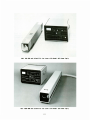
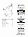
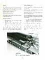
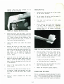
Model 168 OEM and Sclentlf1c ion Laser with Model 265 Power SuppiY••••••••••••••••••••••••••••••••III
Electron Orbttals ••••••••••••••••••••••••••••••••••••••••••••••••••••••••••••••••••••••••••••••••• 1-1
A Four-Level Laser Transition Scheme••••••••••••••••••••••••••••••••••••••••••••••••••••••••••••··1-3
Energy Levels of Argon Transltlons •••••••••••••••••••••••••••••••••••••••••••••••••••••••••••••••• l-4
Model 168 Speclfl~tlons •••••••••••••••••••••••••••••••••••••••••••••••••••••••••••••••••••••••••• 1-8
Model 168 Output Power Speclflcatlons ••••••••••••••••••••••••••••••••••••••••••••••••••••••••••••• l-9
Standard Safety Warning Stgn•••••••••••••••••••••••••••••••••••••••••••••••••••••••••••••••••••••·2-1
Folded Metal Beam Target•••••••••••••••••••••••••••••••••••••••••••••••••••••••••••••••••••••••••·2-1
Model 265 Rear Panel••••••••••••••••••••••••••••••••••••••••••••••••••••••••••••••••••••••••••••••3-2
Model 168/265 lon Laser Thermal Parameters••••••••••••••••••••••••••••••••••••••••••••••••••••••••3-2
Model 314 ion Laser Water Condltlon1ng System Speclflcatlons •••••••••••••••••••••••••••••••••••••• 3-2
Utll1ty Requirements for Model 168 lon Lasers Under Worst Case Service Condlt1ons ••••••••••••••••• 3-3
Laser Head Interior <Anode End>•••••••••••••••••••••••••••••••••••••••••••••••••••••••••••••••••••3-4
Laser Head Interior <Cathode End>•••••••••••••••••••••••••••••••••••••••••••••••••••••••••••••••••3-4
t~de I 265 Front Pane I •• •• ••••••••••••• •• •••••••••••••••••••••••••••••••••••••••••••••••••••••••••• 4-1
v1
LIST OF FIGURES (oon 1 1". >
PAGE
FIGURE
4.2
Front Pane I f'.1eter. •• ••••. • • • • •• • •• • •• •• •• •••• •• •••••• ••••• • • • ••• •• • •••• • • ••• •• • ••••• • ••• • •••• • •• 4-1
Maximum Aval lable Current for Model 168 Verslons•••••••••••••••••••••••••••••••••••••••••••••••·4-2
4.3
4.4
Rear f~lrror AdJustments ••• •• •• ••• •• •••••• • ••• •••••• • • •• ••• • • • • • •••• •••••••••••• ••••• •• •• ••• • •• • .4-3
Anode End Water Connecttons ••••••••••••••••••••••••••••••••••••••••••••••••••••••••••••••••••••• 4-4
4.5
4. 6
Power Supply Control Operations Tests••••••••••••••••••••••••••••••••••••••••••••••••••••••••••·4-5
lon Laser Opt1cs Optlons •••••••••••••••••••••••••••••••••••••••••••••••••••••••••••••••••••••••• 4-9
4.7
5.1
Schematic Representation of Ideal Resonator Allgnment••••••••••••••••••••••••••••••••••••••••••·5-1
5. 2 Cleaning the Mirror Surface •••••• ••••• ••••••••••••••••••••• •••••••••••••••••••••••••••••• ••••••• 5-2
Lens Tissue Folded for Prism Cleanlng ••••••••••••••••••••••••••••••••••••••••••••••••••••••••••• S-3
5. 3
5.4
Misaligned Mirrors Cause Lasing at Reduced Power•••••••••••••••••••••••••••••••••••••••••••••••·5-5
5.5
Misaligned Plasma Tube Causes Lasing at Reduced Power••••••••••••••••••••••••••••••••••••••••••·5-5
5. 6
Prism Alignment Adjustment S cre~s••••••••••••••••••••••••••••••••••••••••••••••••••••••••••••••·5-6
5.7
P lasma Tube Alignment Adjustments•••••••••••••••••••••••••••••••••••••••••••••••••••••••••••••••5-7
5.8
Vertical Search••••••••••••••••••••••••••••••••••••••••••••••••••••••••••••••••••••••••••••••••·5-12
5. 9
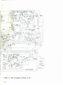
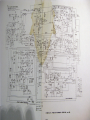
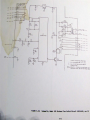
Schematic, Automatic Pressure Control Circui t - Model 168-01, -31••••••••••••••••••••••••••••••·5-13
5.10 Schematic, Model 265 Proteus Flow Switch Clrcult•••••••••••••••••••••••••••••••••••••••••••••••·5-14
5. 11 r.4o del 265 Sche matic •• ••••••••••••••••••••••••• ••••• ••••••••••••••••• •••••••••••••••••••••••••••·5-15
6 .1
Gas Fill
Indicator ••••••••••••••••• ••••• ••••• •••••••••••••••••••••••• •••••• ••••••••••• ••• ••••••• 6-2
Sl
~ITS
The fo ll owin g System lnte rnatlon a I CSI) units, abbreviations, and prefIxes are used In Spectra-Physi cs
ma nual s :
Quantity
Unit
ma ss
le ngt h
t i me
f re quen cy
force
e ne r gy
power
e lec tric current
e lectrlc charge
e le ctric potential
res I s tance
Inductance
ma gnetic flu x
mag netic flux density
l uminous Intensity
t empe r ature
k llogram
meter
second
hertz
newton
joul e
watt
ampere
coulomb
volt
ohm
henry
weber
tesla
candela
kelvin
Abbreviation
kg
m
s
Hz
N
J
w
A
c
v
0
H
Wb
T
cd
K
vii
Prefixes
tera
glga
mega
kilo
decl
cent I
mill I
micro
nano
plco
atto
( 1012)
( 109)
( 1o 6 >
( to3)
( 10- 1>
( 10-2)
(10- 3 >
uo-6>
( 10-9 >
uo-12>
( 10-18)
T
G
M
k
d
c
m
f.l
n
p
a
INTRODUCTIO,.
z
z
X
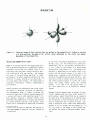
Figure 1.1:
Elecrrons occupy disTincT orbi-tals fflaT are defined by the probabiliTy of finding an elecrron
aT a given posiTion. ffle shape of ffle orbi-tal being de1er•lned by ffle radial and angular
dependence of the probabl I 11-y.
EMISSION N£J ABSORPTION Of LIGHT•
by the radla I and angular dependence of that prob-
laser Is an acronym derIved from "II ght amp II fIcation by stimulated emission of radiation." Thermal
ability, e.g., all "s" orbitals are spherically
symmetrical, and all "p" orbitals surround the x ,
y, and z axes of the nucleus In a double-lobed
radiators,
-
such as the sun,
-
scatter
configuration (see Figure 1.1>.
light In all
The energy of an
But because
electron Is determined by the orbital that It occupies, and the overall energy of an atom- Its
the laser Is an oscillating amplifier of light,
and because Its output comprIses photons that are
Identical In phase, direction, and amplitude, It
Is unique among light sources.
Its output beam Is
energy level - depends on the distribution of Its
electrons throughout the available orbitals. Each
atom has an array of energy levels: the level with
the lowest possible energy Is called the ground
singularly
state,
directions, the Individual photons having no definite relationship with one another.
directional,
Intense,
monochromatic,
Radiant emission and absorption take place within
the atomic or molecular structure of materials.
The
contemporary
model
of
atomic
structure
and
higher
energy
levels
are
excited
states.
If an atom Is In Its ground state, It
will stay there until It Is excited by externa I
forces.
and coherent.
l-1ovement from one energy level to another (a transition) happens when the atom either absorbs or
de-
scribes an electrically neutral system composed of
a nucleus with one or more electrons bound to ft.
emits energy.
Upward transitions can be caused by
Each electron occupies a distinct orbital that
represents the probabl I tty of finding the electron
at a given position relative to the nucleus. Each
orbital has a characteristic shape that Is defined
collision with a free electron or an excited atom,
and transitions In both directions occur as a resu It of I nteractl on wIth a photon of II ght. Consider a transition from a lower level whose energy
content Is E 1 to a higher one with energy E2 • It
to describe the portion of
to
will only occur If the energy of the Incident pho-
*"Light" will be used
ton matches the energy difference between
I .e.,
the electromagnetic spectrum from far Infrared
ultraviolet.
1-1
levels,
of available energy levels exists with nearly all
atoms In the ground state.
Since the rate of absorption of all frequencies exceeds that of emission, the absorption coefficient at any frequency
Is positive.
11 I
where h Is Planck's constant, and
v Is the fre-
quency of the photon.
Likewise, when an atom excited to E2 decays to E1 ,
It loses energy equal to E2-E 1• Because Its tendency Is toward the lower energy state, the atom
may decay spontaneously, emitting a photon with
energy hv and frequency
It enough light of
populations can be
these conditions the
ulated emission are
frequency vIs supplied, the
shifted until N2 =N 1 •
Under
rates of absorption and stimequal, and the absorption co-
efficient at frequency vIs zero.
If the transition scheme Is limited to two energy levels, It Is
Impossible to drive the populations Involved beyond equality; that Is, N2 can never exceed N1 be-
121
Spontaneous decay can also occur without emission
of a photon, the lost energy taking another form,
e.g., transfer of kinetic energy by col IIston with
another atom.
An atom excited to E2 can also be
stimulated to decay to E1 by Interacting with a
photon of frequency v, shedding energy In the form
of a pair of photons that are Identical to the Incident one In phase, frequency, and direction. By
contrast, spontaneous emission produces photons
that have no directional or phase relationship
cause every upward transition Is matched by one In
the opposite direction.
However, If three or more energy levels are employed, and If their relationship satlsltles cartaln requirements described below, addltlona I excitation can create a population Inversion, In
whIch N2>N 1•
A model four-level laser transition scheme Is depleted In Figure 1.2(a).
A photon of frequency
v 1 excites or "pumps" an atom from E1 to E4 •
If
the E 4 to E 3 transition probability Is greater
than that of E4 to E1, and If E4 Is unstable, the
atom will decay almost Immediately to E 3 •
If
atoms that occupy E3 have a relatively long life-
wIth one another.
A laser Is designed to take advantage of absorption, and both spontaneous and stimulated emission
phenomena, using them to create conditions favorable to light amplification. The following paragraphs describe these conditions.
time, the population wl II grow rapidly as excited
atoms cascade from above.
The E3 atom will eventually decay to E2 , emitting a photon of frequency
v2 •
Finally, If E2 Is unstable, Its atoms will
rapidly return to the ground state, El' keeping
the population of E2 small and reducing the rate
of absorption of v 2 •
In this way the population
of E3 Is kept large and that of E2 remains low,
thus estab llshlng a popu latlon lnvers !on between
E3 and E 2 • Under these conditions, the absorption
coeff I clent at v 2 becomes negatl ve. Ll ght Is amplified as It passes through the material, which
Is now called an "active medium." The greater the
population Inversion, the greater the gain.
POPUU\T ION INYERS ION
The absorption coefficient at a given frequency Is
the difference between the rates of emission and
absorption at that frequency.
It can be shown
that the rate of excitation from E1 to E2 Is proport I on a I to both the number of a toms In the I ower
level CN 1 l and the transition probability.
Similady, the rate of stimulated emission Is proportional to the population of the upper level CN 2 >
and the transition probability.
Moreover, the
transition probability depends on the flux of the
Incident wave and a characteristic of the transltlon ca lied Its "cross section."
It can a I so be
shown that the transition cross section Is the
same regardless of direction. Therefore, the absorption coefficient depends only on the difference between the populations lnvol ved, N1 and N2 ,
and the flux of the Incident wave.
A four- I eve I scheme, II ke that descrIbed above,
has a distinct advantage over three-level systems,
In which E1 Is both the or! gin of the pumping
transition and the terminus of the losing tronsltlon.
In the four-level arrangement, the first
atom that Is pumped contributes to the popu latlon
Inversion, while over ha If of the atoms must be
pumped from E1 before an Inversion Is established
In the three-level system.
When a material Is at thermal equilibrium, a
Boltzmann distribution of Its atoms over the array
1-2
/
/
/
/
/
/
/
/
E3
4p
Visible Laser Transition
Pumping Transition
4s
E2
''
E,
''
At
3sf
Ionizing Transition
~ ·------~~~~--Ar
....,
ground
6
(b)
(a)
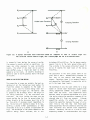
Figure 1.2:
A ~yplcal four-level laser ~ansl~lon scheme (a) compared to tha~ of visible argon
One collision Ionizes neu~al argon. and a second pu1111ps the lon 1o an excl1ed sta1e.
(b).
In commercIa I I a ser desIgns itte source of exc Itatlon energy Is usually optical or electrical. Arc
be between 400 and 600 nm. The lon decays spontaneously from 4s to the Ionic ground state, emit-
lamps are often employed
lasers.
The output of one
ting a photon In the vacuum ultraviolet (about 74
nml as It vacates the lower level of the lasing
pump another,
e . g.,
a
to pump solid-state
laser can be used to
liquid dye
laser
transition.
Is often
pumped by an lon laser.
An electric discharge Is
gene rally used to excite gasseous media like argon
or krypton.
The population In the Ionic ground state at any
given time Is smal I. Recombination processes re-
ARGON AS HI EXCITATION M::DIUM
turn
Ions to the neutral
atom energy
level
scheme.
Therefore, there Is no tendency toward a
self-absorption "bottleneck"
Figure
1.~(b),
and Its visible energy
gram Is depleted In Figure 1.3.
Is pumped to the 4p energy
level
The neutral
level -
The existence of only two lower states for a large
dia-
number of
atom
strong competition between I lnes with a common
lower level may exist.
Such competition would
the origin of
either directly to the 4p energy level <E 3 l or to
E4 , from which It cascades almost Immediately to
4p. The 4p Ions wll I eventually decay to 4s <E 2 >,
slngle-1 lne operation Improves the power of principal lines by less than 10%.
Even those upper
state populations that are shared by more than one
laser transition only exhibit minor competition
effects.
Therefore, the use of a prism or other
emitting
a photon either spontaneously or when
stimulated to do so by a photon of equivalent energy. The wavelength of the photon depends on the
energy
levels
Involved,
but
It
visible laser transitions suggests that
manifest Itself as Improved performance of a given
line during single-line operation, compared to Its
strength when a II I I nes are present.
A I though
competition exists,
Its effect Is minor, and
the lasing transition - by two coli Is Ions with
electrons.
The first Ionizes the atom, and the
second excites the lon from Its ground state <E 1 l
specific
(a population bul ld-
upl In the lower laser levels.
The properties of argon are probably the best understood of all the Ionized gas laser media; Its
transition scheme Is compared to the model In
w I II
dispersing element
1-3
In continuous-wave
(cwl argon
--.,..--- 112 4p 2 0
s
3/2 } 4p 2p0
1/2
;~~
} 4p 2oo
1/21
3/2
4 0
4p D
5/2
5/7
4s 2p { 1/2
3/2---~
Figure 1.3:
Energy levels of tf1e 4p - 4s argon lon laser 1ransl"tlons
Ton lasers Is not necessarily advantageous, except
In single-line applications.
varies approximately as the square of the Input
power over a large range of operating parameters.
Most of the visible laser transitions In a continuous wave argon I on laser have approximate I y the
same power-to-gain ratio as the 488 nm line, al-
A magnetic field,
though
they
less gain.
are
weaker
than
that
line
The 514.5 nm line, however,
and
Induced by a solenoid surround-
Ing the plasma tube, tends
away from the tube wa I Is.
to force
electrons
Since they are not
lost, the electrons are subjected to the plasma
discharge and the energy distribution of the tree
have
Is an ex-
ception. Whl le Its gain Is only about 1/4 that of
the 488 nm line, Its output Is approximately 25%
greater, provided the gain Is sufficient to overcome I nterna I I osses.
The upper state of the
electron population rises. Since the upper energy
levels can only be populated through collisions
between Ions and free electrons having at least
the energy of the state beIng excl ted, the presence of the magnetic field enhances the population
Inversion.
514.5 nm line Is In a dl fferent tam II y of I eve Is
than that of most of the other transitions and the
difference In atomic constants changes the powerto-gaIn ratIo.
The magnetic field also causes Zeeman splitting of
the laser lines. These split lines have elllptlca I poI ar I zatl on.
S I nee the pI asma tube wIndows
The relationship of !on laser gain to Input power
Is quite different from that of other lasers. The
population
will only transmit vertically polarized lines, the
energy of the split lines Is lost.
Inversion requires more than one col IIston to
reach the upper state of the transition and the
gain varies approximately as the square of the
current density.
The close relationship between
Output power, Increased by an enhanced population
Inversion and decreased by the Zeeman effect, depends directly on the strength of the magnetic
excitation
process
that
produces
the
current density and Input power density suggests
that high Input power densities are desirable for
maximum output power.
The output power, In tact,
field.
There
each I lne.
1-4
Is
an
optimum
field
strength
tor
Low porosity Is Important for three reasons.
First, the bore must be vacuum-tight; porous mater I a Is can't sustaIn a vacuum.
Second, porous
materials provide traps for contaminants that
TifE RESONANT <l"TICAL CAY ITY
A resonant cavity, which Is defined by two mirrors, provides feedback to the active medium.
Photons that are emitted para I lei to the cavity
ax! s
are
reflected,
other excited Ions.
returnIng
to
Interact
will
outgas during operation.
Third, the more
porous the mater! a I the greater the lnterna I sur-
with
Stimulated emission produces
face area of
the bore and the greater the dep le-
two photons of equal energy, phase, and direction
from each Interaction.
The two become four, four
t! on rate of the fill gas.
become el ght, and the numbers continue to Increase
geometrically until an equl llbrlum between excita-
The bore must be exceeding! y strong to withstand
mechanical and thermal shock. Moreover, the bore
tion and emission Is reached.
must maintain
Its
Integrity under bombardment by
the discharge.
It must not flake or powder,
contaminating plasma tube windows from within.
Both mirrors are coated to reflect the wavelength,
or wavelengths, of Interest while transmitting all
To start and maintain an arc discharge, the elec-
others. One of the mirrors - the output coupler transmits a fraction of the energy that Is stored
tr I ca I conduct! vi ty of the gas must be hIgher than
within the cavity, and the escaping radiation becomes the output beam of the laser.
the electrical conductivity of the surrounding
walls.
In order to start the discharge, a high
For broad-band
the
mirrors
voltage pulse must be applied across the gas. The
dielectric strength of the bore material must be
reflect a number of
lines within a
wavelength range (about 70 nm maximum).
limited
Several
sufficient to allow It to withstand such a start
pulse without breakdown.
sets of
(a 11-llnes) operation
broad-band optics are available to cover
To function properly In a high-vacuum evnlronment,
dIfferent groups of I aser II nes.
the bore material must have an extremely low vapor
pressure and be free of extraneous materials with
higher vapor pressures.
Adding a prism to the cavity limits oscillation to
a single line. The dispersion of the prism allows
only one line to be perfectly aligned with . the
high ref lector, so the t i l t of the prism determines which line will oscll late.
Of all the possible materials or combinations of
materials that are presently available for plasma
PLASMA TUBE
tube bore construction, beryllium oxide (Be0) has
proven Itself to be the material of choice for
tubes of high reliability and long life.
The plasma tube Is the most critical
any
Jon
laser.
component of
0
It must provide the optical gain
necessary for lasing by sustaining a high-currentdensity arc discharge through Its bore.
The primary consideration
In plasma
tube
design
Is
0
the
choice of bore material.
The Ideal material provides a combination of the following properties:
high thermal conductivity, low porosity, high me-
0
chanical strength, electrical Insulation, high dielectric
strength,
high
purity,
low
vapor
pressure.
Jon
watt
lasers are
of
output,
low-efficiency devices.
at
least
1.5
kW
of
The
therma I
conduct! vi ty
of
BeO
Is
0.45 cal cm-1 sec-1 oc-1, a value higher than
that of most metals.
Its modulus of rupture
Is greater than
2x13 kg cm- 2, whl le Its modulus of elasticity
Is greater than 3.5x10⁶ 0-cm-2.
Its resistivity Is 101 6 O-cm-1.
V cm-1.
0
Its dielectric strength Is 1.8x10⁶
0
Its vapor pressure Is less than 10-11 mm Hg@
120°C.
The BeO used In Spectra-PhysIcs pI asma tube
bores Is guaranteed at least 99.5% pure.
0
For each
electrlca I
TifE tiDEL 168 ION LASER SYSTEM
power must be dissipated as heat In the plasma
tube bore.
Eff lclent heat transfer, from the Ins I de of the bore to the coo II ng water, Is essential; thus the need for high thermal conductivity.
The Spectra-PhysIcs Mode I
168 argon
and
krypton
Jon lasers provide optimum cw output power for a
broad range of OEM applications.
These Include
1-5
Industrial spectroscopy, data recording and retrieval, biological cell sortl'ng, retinal surgery,
A set of optics for either single-line or alllines operation Is supplied with each laser. The
and endoscopic coagulation.
optics are
o
changed.
splitter
Argon lasers are aval lable In four baste versions,
broad band or single
line,
Krypton lasers are available In four
versions: standard or automatic pump,
threaded mounts
that can
be
for single-line operation.
baste
TEMoo
f~odel
or multlmode.
The krypton lasers provide
broad band output In the red wavelengths and
1688 lasers employ a fixed aperture, located
Inside the cavity near the
produce a TEM 00 output beam.
moderate power In the near Infrared.
The Krypton Automatic Pressure Control
In
stabilizer. AI 1-llnes operation Is obtained using
a high reflector.
An assembly containing a Brewster-angle prism and high reflector Is employed
TEMoo or
multi mode.
0
held
The output mirror holder Includes a beam
for the built-In power meter and light
output
coupler,
to
Plas1111 Tube
Pump
Laser Incorporates an automatic krypton presAll
Model
168
Lasers
use
rugged
BeO
and
glass
sure control pump and related electronics.
In addition to the standard krypton wave-
plasma tubes built with
lengths, thIs mode I performs we II In the
pressure-sans I tl ve green-ye I low region of the
long
path
spectrum.
adequate gas conductance wh lie prevent! ng tube
fa II ure due to an arc dl scharge through the return
Refer
Output
to
description of
versIon numbers.
Power
the
Specifications
available
models
for
a
and the
The laser system Is composed of the Model
Laser Head and the Mode I 265 Power Supp I y.
laser
head
contains
the
resonator
with
hard-seal
technology for
life and high reliability.
The gas return
Is a separate, large-bore tube that allows
line.
The high thermal conductivity, strength,
and mechanlc11l stability of BeO make It an Ideal
material for plasma tube construction.
Its resistance to erosion, caused by borrbardment by the
high energy plasma, assures long tube life.
The
bore segments 11re Joined by a proprietary, non-
168
The
laser
metallic bonding process.
The fused-silica
win-
optics, plasma tube, and magnet. The power supply
contains all of the electronic circuits necessary
to create, sustain, and monitor the plasma tube
dows are hard-sea led to the tube at Brewster 1 s
angle, thereby allowing a thorough, hlgh-temperllture bakeout of the entire tube during processing.
discharge;
to
monitor
power;
to
supply
The result Is a contamination-free
long life expectancy.
and
and
control
and regulate
the
output
the magnetic
tube
with
a
f leI d.
Model 168 argon and krypton lasers use the highest
grade of optical
THE LASER I£AD
Resonator
A massive extruded aluminum resonator provides
support for the plasma tube, optics, and magnet.
The excellent thermal conductivity of aluminum
assures uniform distribution of heat throughout
the structure, keeping thermal gradients to a minImum. As the temperature of the unit changes, Its
dimensions
change
uniformly,
with stiff springs.
resonator, combined
reduce
available.
Fused
All argon models employ a gas fill reservoir connected to the pI asma tube through a
actuated valve that Is controlled by
located within the power supply.
thereby maintaining
Most krypton
alignment and beam-pointing stability. The aluminum mirror mounts are held against the resonator
springs,
fused quartz
quartz 1s the material of choice for visible operation because of Its high purity, uniform optical
and mechanlca I properties, and ability to be polIshed to a superb optical finish.
vibrations
of
lines are pressure sensitive.
A combined pump and fill mechanism provides the
ability to raise and lower gas pressure on laser
models 168-01,-31,-41,-71 The pump can be operated
The mass of the mounts and
with the stiffness of the
mechanical
laser
solenoIdcircuitry
automatically, or It can be operated manually for
the
opt I mum
performance
at
sans I tl ve krypton II ne.
mirrors, thereby reducing frequency Jitter.
1-6
a
selected
pressure-
THE KX>EL 265 POWER SlFPL Y
switch activates the gas till circuit, adjusting
the pressure to opt! mum performance I eve Is.
The
cl rcu It automat! ca II y prevents overt Ill. When the
automatic pressure control system Is used with a
The tu I I y regu I a ted power supp I y contro Is the dIscharge current to provide consistent laser performance despite fluctuations In line voltage.
A
separate circuit provides current to the magnet.
The magnetic field Is continuously adjustable all owIng max I mum petormance at a II I aser II nes.
krypton laser, spec I a I electronIcs monItor plasma
tube pressure and automat! ca II y control the pump/
till system tor optimum performance.
A II ght stab Ill zer circuit uses feedback from a
photo detector In the laser head to control output
power by regulating plasma current.
Current can
a I so be contro lied manua II y from the front pane I
of the power supply.
Option 411-813 adds electronics to the Model 265
Power Supply that allows modulation and remote
control of the laser.
The laser output can be
modulated at rates up to 10 Hz.
Option 411-814 adds a circuit to the Model 265
Power Supp I y that automat! ca II y starts the laser.
The photo detector sl gna I can a I so be fed to the
multi-purpose meter on the front panel. The meter
can
monitor output power, plasma current, gas
pressure, or the condition of the plasma current
regu I a tor.
An audible alarm warns of low gas pressure.
The start sequence Is Initiated 30 sec after the
cl rcu It breaker on the front pane I of the power
supply Is closed.
The following tables provide detailed specifications for all of the aval lable Model 168 versions.
A key
1-7
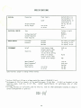
SPECIFICATIONS
PHYSICAL
Power Supply
Dimensions
Laser
Shipping Weight
Cavity Length
ELECTRICAL SERY ICE
w/o prism
w/ prism
Type
3-phase w/ earth
ground
208±8% v
38A
13.1 kW
Voltage Requlred 1
Current Required
Power Required
WATER SERY ICE
Flow Rate
Pressure
PERFORMANCE
Stability
Beam Dl ameter3
Beam Divergence}
Polar I zatlon
Mode Spacing
42.5x27.7x41.9 em
16.7x10.9x16.5 In
14.9x14.4x100.1 em
5.9x5.7x39.4 In
105 kg, 232 lbs
0.9 m
0.95 m
Minimum
Minimum
Maximum
8.5 1/mln, 2.2 g/mln
1.8 kg/cm2, 25 psi
3.5 kg/cm 2, 50 psi
Light Control Mode
Current Control Mode
Light Control Mode
{In any 30 min period,
after 2 hr warmup)
Current Control Mode
{after 30 mIn warmup l
0.2% rms
1%
w/o prl sm
w/ prism
±0.5%
1.25 mm
0.69 mrad
Vert I ca I
167 MHz
158 MHz
Specifications subject to change without notice.
Versions 168-09 and -49 have a voltage regulation range of 208+8%-5% V {ac.l
2 Performance at 514.5 nm {argonl, at the specified power, 10 Hz-2 MHz.
At 647.1 nm (krypton>, at the
specified power, 0.3% rms, 10 Hz-1 MHz.
Contact Spectra-Physics for performance data at other
wavelengths.
3 For TEM
2
00 versions: at 1/e points, data for 514.5 nm. Data for other wavelengths {assuming no change In
optical configuration) Is given by:
DI A< 1 l
DIAC2l
1-8
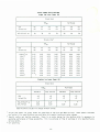
OUTPUT POWER SPECIFICATIONS
Argon lon Laser Power (W)
Br oad Ban d
Multi mode
TEMoo
OEM
Sc ie nt ifi c
457. 9- 514. 5 nm
-57
-17
- 56
-1 6
2W
-58
-18
-59
- 19
-67
-27
- 68
-28
-69
-29
5W
3W
4W
5W
4W
3W
SIn g I e - Ll ne 1
Multi mode
TEMoo
OEM
Sc ie ntifi c
to9o . o2 nm
528 .7 2
514 . 5
501.7
496 . 5
488 . 0
476 . 5
472 .7
465 . 8
457. 9
454. 5 2
- 46
- 06
-47
- 07
- 48
-08
- 49
-09
-77
-37
-78
-38
-79
-39
0. 02
0 .1 5
0. 80
0 .1 0
0 . 28
0.70
0 . 25
0. 05
0. 05
o . 11
0.03
0. 25
1. 20
0. 20
0.40
1. oo
0.35
0.13
0. 07
0. 20
0.05
0. 04
0. 30
1.70
0.30
0. 60
1. 30
0. 60
0. 25
0.1 3
0.30
0.10
0.05
0. 34
2. 00
0.40
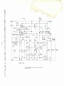
0.70
1.50
0.75
0.30
0. 20
0. 35
0.12
0.03
0.25
1 .20
0.20
0.40
1.00
0.35
0 .13
0.07
0.20
0.05
0.04
0.30
1. 70
0.30
0.60
1. 30
0. 60
0.25
0.13
0.30
0.10
0.05
0.34
2.00
0.40
0.70
1. 50
0.75
0.30
0.20
0.35
0.12
3
Krypton lon Laser Power (W)
Broad Band
Multi mode
TEMoo
Standard
OEM
Scientific
752.5-799 .32 nm
647.1-67 6 .4
Pump Ve rsion
-61
-21
-41
-01
0.25
0.60
0. 25
0.60
Standard
-51
-11
Pump Version
-71
-31
3
o.ao
3
0.80
Spec i fications subject to change without notice.
Sln g le -llne powe rs for argon lasers are specified at 514.5 nm and 488.0 nm only. Other powers Indicated
are nominal; firm specifications are aval table with special testing at extra charge.
2 Specla I optics and testing required. There Is an extra charge for the testing which Is necessary to
guarantee performance at these wavelenths. Thi s Is available at time of purchase or at a Spectra-Physics
Service Center.
3 Not specified.
1-9
CAUTION
The Spectra-PhysIcs Mode I 168 Laser Is a
Class
IV-High
Power
Laser
whose
beam
Is, by definition, a safety and fire
hazard.
Take precautions to prevent
accidental exposure to both direct and
reflected beams.
Diffuse as well as
specular
beam ref lectlons can
cause
severe eye or skIn damage.
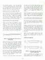
FIGURE 2.2:
PRECAUTIONS FOR THE SAFE <PERATION Of QASS IV-
Folded Metal Beam Target
HIGH POWER LASERS
o
0
Do not attempt to view either a direct or re-
Set up shields to prevent stray reflections
from escapIng the I aser operatl ng area.
flected beam; even a diffuse beam reflection
0
0
WARNit«7:
may be hazardous.
Avoid blocking direct or reflected beams with
any part of the body.
Establish a controlled-access area for laser
operation. Limit access to those persons who
Both the Mode I 168 and Its power supp I y
contain electrical circuits operating at
dangerous voltage and current levels.
are trained In laser safety principles.
light
level
Exercise
0
Maintain a high ambient
In
0
eye remains constricted, reducing the possibility of damage.
Post warning signs prominently near the laser
HIGH V<l...TAGE N«> aJRRENT
the
extreme
caution
whenever
the
covers of the laser head or power supply
are removed.
Do not touch high voltage
laser operation area so that the pupil of the
terminals or components.
CAUTION
operation area.
Use of controls or adjustments or
per-
formance of procedures other than those
specified herein may result In hazardous
radiation exposure.
Operating this laser without due regard for these
precautions or In a manner that does not comply
wIth recommended procedures may be dangerous.
At
all times during Installation, maintenance or service of your laser, avoid unnecessary exposure to
laser or collateral radiation that exceeds the accessIble emIssIon II mIts II sted In Performance
Standards for Laser Products, 21 CFR 1040 10(d).
FIGURE 2.1:
0
0
0
Sillndard Safety Warning Sign
Fo I I ow Ins tructl ons contaIned In thIs manu a I for
proper lnsta llatlon and operation of your laser.
We recommend the use of protect! ve eyewear when-
Provide enclosures for beam paths whenever
possible.
To avoid unnecessary radiation exposure, keep
the
I aser cover
In place
durIng norma I
operation.
Set up a meta I beam target to capture the
laser beam and prevent accidental exposure.
ever possible; selection depends on the energy and
wavelength of the laser beam used as wei I as operating conditions.
Consult relevant OSHA, ACGIH or ANSI standards for
further guidance.
2-1
SQ\miLE <I' M\MtelNtt£ tEC£SSH\l 10 t(EB> MI>EL
1688 LASERS IN CDIA..IANCE WITH <DRH 21 a=R QIAPTER 1. SUBCHAPTER J. PARTS 1040.10 Nl> 1040.11
This
OOlER \KT£R..OCKS
laser product compiles with Title 21 of the
United States Code of Federal Regualtlons, Chapter
1 , Subchapter J, Parts 1040.10 and 1040.11, as
app I I cab I e.
To maIntaIn comp II a nee wlth these
regulations, once a year or whenever the product
has been subjected to adverse environmental conditions
(e.g.,
fIre,
flood,
mechan lea I
shock,
spilled solvent) check to see that all features of
the product listed on the radiation
control
drawing <Figure 2.5) function properly.
Also
Insure
that all
required
labels are
firmly
attached.
FIGIRE 2.:5:
Verify that
(Interlock)
removal of the remote control
plug
<Figure
2.5
and
3.1)
An Interlock th11t prevents !lccldent!ll electric
shock or exposure to coll!lter!ll
r!ldl!ltlon
Is
Incorporated In the cover of the Model 168B.
prevents operation of the laser.
e~~nnot
2
Verify th11t the
w I thout the key.
3
Verify th11t the emission lndlc!ltor provides 11
visible slgn!ll when the Instrument emits
l11ser r!ldl!!tlon that exceeds the !lccesslble
laser
be
turned
Remov11l of the cover opens a protective circuit,
tripping the m11ln circuit bre11ker. The l11ser will
not oper11te until the cover Is on or an Interlock
defeat plug h11s been lnst!llled.
The cover c~~nnot
on
be
Jnst11lled
until
the
defe11t pi ug
Is
removed.
Shut down the laser before removing the plug.
emission limits for Cl11ss 1*.
Also verify
th11t the slgn~~l provides 11n 11dvance W!lrnlng
sufficient to 111 low !!pproprl!lte 11ctlon to
11vold r!ldl!!tlon exposure.
4
Contr Interlock Defea't Plug
careful
to !!Void high voltllge termln11ls:
f!lm Ill 11r I ze yourse If wIth the lr loe~~ tlons, wh lch
!Ire Identified by warning l11bels.
Be
Verify th11t the be11m blocker !1ctu11lly blocks
access to l11ser emission.
EEAM ll...CX:KER
5
Verify th11t the s11fety Interlock stops emission of l11ser or coll!lter!ll- r!ldlatlon upon
remova I or d I sp I 11cement of the Inter I ocked
p11rt of the protective housing.
Model 1688 l11sers h11ve a mech!lnlcal shutter th11t
e~~n be oper11ted using 11 thumbwheel that protrudes
through the top cover ne11r the emission lndlc!ltor.
6
Verify th11t, when the s11fety Interlock Is
defe11ted, the defe11t plug Is cle11rly visible
11nd prevents lnstllll!ltlon of the cover.
* 0.39 ~o~lf for cw oper11tlon where output Is limited
to the 400-1400 nm range.
** Any electronic product r!ldl!!tlon, except l11ser
r!ldl!!tlon, emitted by 11 laser product !IS 11 result
of or necess11ry for the oper11tlon of 11 l11ser
lncorpor11ted Into that product.
FIGIRE 2.4:
2-2
Model 1688
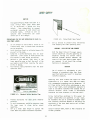
a..
Blocker
~
SPECTRA-PHYSICS INC .
1250 WEST MIDDLEFIELD ROAD
MT. VIEW, CALIFORNIA 94042
J
MANUFACTURED:
MONTH
YR
:1688
MODEL
S/ N
THIS LASER PRODUCT COMPLIES
WITH 21 CFR 1040 AS APPLICABLE
MADE IN U.S.A.
Certification Label
WarnIng Logotype
FIGURE 2.5:
VISIBLE
AND INVISIBLE•
LASER RADIATION IS
EMITIED FROM THIS APERTURE
Model 1688 Radiation Control Drawing
La ser Sa fe ty Feature
Certification Label
Warning Logotype
Aperture Label
Cover Interlock Label
Electromagnetic Rad i ation Label
Remote Contr ol (In t er lock) Plug
Power Supp ly Em i ssion Indicator
Beam Attenuator
MASTER Key Switch
Laser Head Emission Indicator
Cover Inter Iock
LOC8tlon
( AVOID EXPOSURE )
Aperture Labe I
2
3
4
5
6
7
8
9
VIS I BLE AND INVISIBLE
HAZARDOUS ELECTROMAGNETIC
RADIATION WH E N OPEN AND
INTERLOCK DEFEATED*
10
' SEE MANUAL
11
Cover lnierlock Label
VISIBLE AND INVISIBLE
LASER RADIATION WHEN OPEN
AND INTERLOCK DEFEATED
AVOID EYE OR SKIN EXPOSURE
TO DIREC T OR SCATTERED
RADIATION *
' SEE MANUAL
Electromagnetic Radiation Label
FIGURE 2.6:
2-3
Model 1688 Warning Labels
INSTALLATION
U~ACKING
YOUR LASER
0
sever a I ba II
drIvers for pI asma tube a II gn-
ment <the Allen wrench set supplied with the
Inspect each component of the system carefully as
you unpack ft.
If you notice any damage, such as
dents or scratches on the laser head or power supply cases, broken knobs or switches, or a broken
plasma tube, notify the shipper and your SpectraPhysics
upon
meet
wIll
sales
representative
Immediately.
o
laser Is adequate, buta set of ball drivers
that Includes three 125 and four 123 wrenches
makes alignment a much simpler process)
a thIrd water hose for the over-pressure relief drain
If,
Installation, the laser falls to operate or
performance specifications, Spectra-Physics
arrange for repaIr or rep I a cement wIthout
ELECTRICAL OONNECTIOHS
The
power
supp I y
requIres
208±8%
waiting for your claim against the carrier to be
electrical service, rated at 50 A.
settled.
should be
less than 2.4 m (8 ft)
V three-phase
The switch box
from the power
Connect the ~n lead 1o earth ground.
supp I y.
not neutral. Connect the remaInIng three leads to
If you file a
Retain ffle shipping containers.
damage claim, you may need them to demonstrate
that the damage occurred as a resu It of shIppIng.
If you need to return the laser for service, the
specially designed crate assures adequate protec-
the legs of the three-phase servIce; sequence
not Important.
If a dIsconnect pI ug Is used,
must be rated for at least 50 A.
Is
It
WARNING
tion.
You will find the following Items In the accessor i es kit In which this manual was packed:
Do not exceed 230 VI
If only >230 V
three-phase Is available, you must use a
transformer to step down to 208 V.
o
A tool kit that contains all of the tools you
will need to align and maintain your laser,
Contact your Spectra-Physics field engineer for details.
Inc I udlng: fuses, extra hose washers, a set
of A I I en wrenches for beam a II gnment, a box
wrench for unlocking the magnet for align-
Place both the laser head and power supply In
their operating positions. The standard length of
ment,
a
mirror
wrench
for
mirror
remova I,
the umb Ill ca I between the I aser and the power
supply Is 2.4 m. Connect the electrical umbilical
forceps and lens tis sue for optics cleaning,
a dispensing bottle for optics cleaning
to the receptacle on the rear panel
0
Two water hoses for system cooling water: you
will need one hose for Inlet water and one
for outflow
supply; Insert the plug Into the jack and press
until the connection Is snug. Tighten the retainIng ring finger-tight.
0
One water filter with three
cartridges: one cartridge Is
WATER CONNECTIONS
25f! m filter
packed In the
of the power
the filter housing
0
to the fittings
A small cardboard box that contains the high-
Connect the laser head water hoses
reflector mirror, a mirror wrench, and two
sets of keys: a pair of master switch keys
and a pair of gas fill switch keys
located beneath the electrical umbilical. Cooling
water may be supplied from an open-loop system
consisting of filtered tap water source and direct
A large ball
driver
for
plasma
tube
removal
connection of the outflow to a drain, provided the
water flow r11te Is at le11st 8.5 1/mln (2.2 US
Is
packed separately.
ga I /m1 n) at a d I fferentl a I pressure* between 2.11
and 3.52 kg/cm2 (30 11nd 50 psi g.)
The Incoming
In addition to these accessories, you will need to
supply several Items, Including:
water service should be at
0
electronic grade (or better) acetone for op-
least 3/4"
*defined as the difference between
back pressure 11nd the Input pressure
tics cleaning
3-1
diameter.
the
exit
Overpressure Relief Outlet
Water Inlet
Remote Control Plug
Umbilical Connector
Water Outlet
F IGtiE 3. 1 : llbllt I 265 Reer Pane I
In the Spectra-Physics 160 series. If you pl~n to
design your own closed-loop system, use the specifications and thermal par~meters ~s a guide.
A 25 ~m w~ter filter Is Included with your l~ser
system.
It prevents blocked w~ter p~ss~ges by removing p~rtlcles from the cool lng water.
lnst~ll
It with 21 shutoff vt~lve on the Inlet side ~nd ~
check vt~lve on the outlet side.
Provide enough
room around the filter to t~llow easy access for
FIGURE 3.2:
Model 1681265 lon Laser The.-.al
Para~~e1'ers
service.
Connect the fl ltered cool lng water to the femt~le
hose f I ttl ng on the re~r pane I of the power supply.
Connect ~ dr~ln hose to the !Mle hose fitting.
Required He21t Dissipation
Required Coolant Flow Rate
Maximum Outlet Temperature
Required Coolant Pressure*
An over-pressure reI lef va I ve protects the l~ser
~nd power supp I y from d~mage due to hIgh water
pressure. It wl II open If cool lng system pressure
exceeds 3.5 kg/cm2 <50 psI g >.
Connect another
drain hose to the over-pressure fitting.
Both
drain hoses IMY be merged with ~ "Y" connection
before they reach the dr~ln. However, If a "Y" Is
used, take ~re to avoid stepping on the outlet
hoses, which ~n cause excessive back pressure.
FIGURE 3.3:
Model 314 lon Laser Waier
<Andl'tlonlng Specifica-tions
Allowed Heat Dissipation
Flltratlon
Delonlzatlon
Deoxygen~tlon
A closed-loop cooling system, such ~s the SpectraPhysics Model 314 Water Conditioner IMY also be
used.
Its specifications, II sted be low, exceed
the ther!MI p~rameters of ~II of the l~sers
13.1 kW
8.5 1/mln
2.2 g~llmln
53°C ( 127°F>
30-50 psi g
40 kW
25 ~m
>0.175 MO-cm
>1 ppm
*defIned as the d If terence be-tween
back pressure and the Input pressure
3-2
the
exit
FIGURE 3.4:
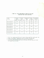
U1"1111"y Requlre.an-ts for Model 168 Jon Lasers
Under Wors-t easel Service Condi-tion s
Maximum
Outlet
Temp2 C"Fl
Maximum
In let
Temp3 ("Fl
Temperature
Change
C"Fl
Power
Consumed
CkWl
AC Current
Requlred4
CAl
-06,-16,-46,-56
127
95
32
10 . 4
28
-07,-17,-27,-37,
-47,-57,-67,-77
127
91
36
11.6
31
-08,-18,-28,-38
-48,-58,-68,-78
127
88
39
12.6
34
-09,-19,-29,-39
-49,-59,-69,-79
127
85
42
13.5
37
-11 ,-21 ,-01,-31
-51,-61,-71,-41
127
88
39
12.6
34
Laser
Version
224.6 V (acl (maximum specified) and 2.2 g/mln (minimum specified) cooling water flow
2 Preset at the factory- temperature at which the thermal Interlock opens
3 Inlet water temperature must be below this value for safe operation
4 Current rating of the three-phase circuit that serves the laser should be at least
10 A higher than this value.
3-3
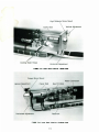
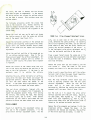
High Reflector Mirror Mount
~-~\
Verti/justment
•
Horizontal Adjustment
FIGURE l.5: l.aser Heed ln'hlrlor
c--. EM!)
Output Mirror Mount
Water Connection
Cavity Seal
Horizontal Adjustment
Fl~
Reservoir
1.6: Laser Heed ln"htrlor CCafflode End)
3-4
OPERATION
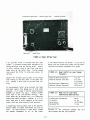
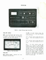
FIGURE 4.1:
Model 265 Power Supply Fron-t Panel
POWER stPPLY a:Jff'Tml.S
50 AMPS - the meter displays plasma tube
current from 0 to 50 A. Read values displayed
on the D-50 seale.
t£TER- the multi-function meter displays plasma
tube current, I aser output power, gas pressure as
a function of tube voltage, and the operating
condition of the tube current regulator.
5 W -
the meter displays output power from 0
Read va I ues dl splayed on the Q-5
to 5 W.
seale.
1 W -the meter displays output power from 0
to 1 W.
Read values displayed on the Q-1
scale.
FILL
the meter displays plasma tube
pressure as a function of tube voltage.
Optimum pressure ranges for argon and krypton
versions of t he Model 168 are color coded on
the meter face:
Ar/blue Is for visible argon
operation; Kr/red Is for krypton operation In
the red (647.1-799.3 nm) range; Kr/green Is
for a I I other krypton II nes.
If the meter
def lectlon, at maximum CURRENT, fa II s within
the color bar corresponding to the operating
wavelength of the laser, tube pressure Is
within Its optimum range.
FIGURE 4.2: Fron-t Panel Mlt'htr
t£TER function se lec1'or - determInes
displayed on the panel meter.
the
va I ue
4-1
If
the
meter
falls
gas pressure
to
I s too
reach
the
I ow and the
color bar,
position,
plasma
tube shou I d
adjusting
the
control
selected by
until
a
predeter-
mined value Is displayed on the meter.
be f !lied.
Mu ltiply
tube current can be
CURRENT
values
displayed on
by a factor of
six
to
vo I tage.
If
co lor bar,
the tube
find
the meter
the 0-50 scale
the actual
deflects beyond
Is overfilled.
When
tube
the METER
5 W pos Itt on,
the
to
Refer to
a
se I ec tor
Is
In eIther the 1 W or
laser output power can
predetermIned
va I ue
by
be adjusted
turn l ng
the CURRENT
control.
the "Gas Fill" Instructions for details.
CONTR>L 14X>E swItch REG - the meter displays the voltage across
the plasma tube current r egulator by finding
the difference between the supply line voltage and the plasma tube voltage.
ter deflection
Is within
the
LIGHT control knob- output power Is stab! I !zed by
sampling the output beam and compensating for flu-
green REG bar,
ctuat ions through feedback to the plasma tube cur-
the regulator voltage Is within Its operating
rent
voltage
If the deflection falls to reach the
regulator.
Minor
the
low.
LIGHT control mode.
line voltage or high plasma
tube
voltage can both reduce regulator volt-
age.
If the meter def lectlon exceeds the REG
range, regulator voltage Is too high.
can
be
arises,
line voltage or
the
check
cause.
the
If
tube
low tube
either
output
When
Ei ther
resonator
Irregularities and other
REG bar, the current regulator voltage Is too
high supply
eIther the CURRENT
If the me-
range.
Low supply
se I ects
control or LIGHT control mode.
beam
can
be
the METER se I ector
5 W position,
misalignments,
disturbances
compensated
Is
In eIther
laser output can
In
for
In
the
1 W or
be adjusted
the
to a
predeterm l ned va I ue by turn l ng the LIGHT contro I.
voltage
condition
voltage by
switching
The usable output range Is 100 mW to 2 W.
the meter display to FILL.
low
the
stabilization
circuit enough
To al-
latitude
operate proper I y, plasma tube current must be
Multiply the value displayed on the 0-1 scale
to
set
at least 2 A below Its maximum rated value.
by a factor of ten to find the actual regulator voltage.
Light stabilization during multi-line operation Is
Impossible
since
there
Is
no
way
to
CURRENT control knob- output power Is stab! I !zed
relative stability of all of the lines
by regulating the plasma tube current.
put beam.
maintained
at
fluctuations
a
selected
value,
Current Is
Independent
assure
the
In the out-
of
FIELD control
In supply lin e voltage.
knob- adjusts
the
axial
magnetic
f leld along the plasma discharge from 500-1000 G.
When the METER function selector Is In the 50 AMPS
The output power of some krypton
hi!!nced
netic
FIGURE 4.3:
Maximum Plas.a Current
for Model 168 Versions
on
the
field.
pump
vers ton
The 647.1
by
line
lines can be enreduct ng
the mag-
Cl!ln be enhanced by
30% and the 520.8 II ne by as much as 80%.
A separ!lte
Argon Versions
assures
There
-06,-46 ••••••••••• 28A
-16,-56,-97 •••••••• 30A
It ng
-27,-37,-67,-77 ••• 30A
-07,-17,-47,-57 •••• 32A
f leI d.
-28,-38,-68,-78 ••• 32A
-08,-18,-48,-58 •••• 35A
-29,-39,-69,-79 ••• 35A
-09,-19,-49,-59 •••• 38A
a
regulated power
stable
magnetic
Is no possibility of
to
the
output
beam
supply
field
for
the magnet
without
ripple.
noise or ripple
through
the
coup-
magnetic
MASTER OONTR>L - the key sw Itch act l va tes the sy s-
Krypton Versions
tem and must be on before the circuit breakers Ci!ln
be closed.
When It Is on the lamp will glow.
-11,-21,-51,-61 •••••••••••••••••••••••••••••30A
-01 ,-31 ,-41 ,-71 •••.•.••••••••••••••••••••••• 35A
Circuit Breaker- connects all power supply circuits to the 208 V ac supply line.
It Is Interlocked with the water flow, cover, and temperl!lture
4-2
monitors
to
~ssure
GAS FILL control - the key switch activates the
gas f I II mechanIsm to Increase pI asma tube pressure. Refer to the "Gas Fill" Instructions In the
Operation section for details.
Improper use of
sate operation.
LINE Indicator la!ips - monitor the three phase
II ne vo I tages wIth respect to one another.
A II
three
lamps glow when power Is applied to the
the Gas Fill system can cause permanent pI asma
tube damage.
(If you have a krypton laser, refer
to Krypton Laser Operation for additional Instructions.)
Model 265.
WATER Indicator la!ips - the WATER ON lamp glows
when water pressure and flow are sufficient for
safe oper~tlon.
The WATER HOT Indicator glows
when the cooling system output Is too hot for safe
oper~tlon; It goes out as soon as a safe water
temperature Is reached.
Such a change can occur
quickly and the WATER Indicator may only glow
momentarily after the laser shuts down.
LASER HEAD OONTRX..S
Horizontal - moves the optlca I axis of the mirror
horl zonta II y.
Vertical - moves
vertically.
LASER Indicator laiiPs - the READY lamp glows when
the system Is ready to start, about 15 sec after
the MASTER CONTROL key switch Is turned ON. Press
the START button to send a high volt~ge pulse to
shrt the plasma discharge.
the
axis of
the mirror
ATTENUATOR- a mechanlca I shutter that blocks the
beam as It emerges from the output coupler.
Horizontal
FIGURE 4.4:
optlc~l
High Reflector Mirror Adjus-t.anb
4-3
TESTING
OONTROL <PERAT ION TESTS
The following tests should be performed before you
attempt to start your laser for the first time.
They are your final assurance that the system
arrived In proper working condition.
Check the key swItches to be sure that they operate smooth I y•
Check to make sure the MASTER CONTROL key will not
pull out when the switch Is ON.
WATER TESTING lHE PLASMA TUBE
Check that each control knob turns smoothly; set
each at Its minimum value.
Remove the laser head cover.
Slowly open the water supply valve until you begin
to hear the water f Iow.
With the MASTER CONTROL switch OFF and the water
supp I y on, app Iy power to the Mode I 265 and check
the following:
Check the following:
0
0
o
Water shou I d enter the tube through the magnet water fitting.
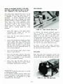
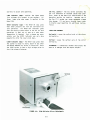
Check for leaks at the anode block (see
Figure 4.5), the hose clamps, and the connect! on at the rear of the power supp Iy. Check
for water drops beneath the power supply.
0
0
All three LINE Indicator lamps should glow.
The WATER ON Indicator lamp should glow.
The WATER HOT Indicator lamp should be dark.
Conduct the power supply tests In figure 4.6.
If your system f11lls any of the above tests, c11ll
your Spectra-Physics representative. If 1111 tests
were satisfactory, go on to "Starting the Argon
Laser." (If you have a krypton laser, refer to
Krypton Laser Operation for starting Instruct! ons.)
If water leaks appear at the fittings or hose
clamps, tighten them to see If the leaks stop. If
they persist, shut off the water supply, drain the
tube and call your Spectra-Physics representative.
FIGURE 4.5: Anode End Vaiw
4-4
Conn~lons
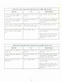
FIGURE 4.6Ca>: Power Supply Control Operation Tests for Mode I 168B ton Lasers
OONOITION
TEST
EXPECTED RESULT
Circuit br eaker OFF , r emot e control p lu g In socke t, ~A S T ER
sw Itch OFF
Move c ir cu it breaker to ON
position
Circuit breaker should not remain
ON
Cir cuit br eake r OFF , remote con trol p I ug In socket, MASTE R
SWItch OFF
Move circuit breake r to ON
position
Circuit breaker should engage and
remain ON; MASTER Indicator la mp
should glow
MASTER sw Itch ON , remote con tro I
plug In socket , circu it breake r
ON
Remo ve remote control plug
fr om r ea r of power supply
Circuit breaker shou I d turn OFF
MASTER sw itch ON, r emo t e contro I
p l ug In socket, c ir cui t breaker
OFF
Turn OFF wate r supply
You shou I d not be able to close the
circuit breaker.
When you restore the water s uppl y,
the WATE R ON Indicato r should glow
and the circuit breaker shou Id
remaIn ON ,
FIGURE 4.6(b): Power Supply Control Operation Tests for Model 168 ton Lasers
OONJITION
TEST
EXPECTED RESULT
Cir cu it brea ker OFF, MASTER key
switch ON
Move c l rcu It breaker to ON
position
The circuit breaker shou I d not
remaIn ON .
Cir cu it breaker OFF , MASTER key
switch ON
Move c l rcu It breaker to ON
position
The circuit breaker s hou l d engage
and remaIn ON, The MASTER OONTROL
I nd lcator lamp should glow.
Turn off water supply
You shou I d not be able to close the
MASTER key switch ON , circuit
breake r OFF
circuit breaker.
When you restore the water suppl y,
the WATER ON Indicator should glow
and the circuit breaker shou I d
remain ON.
4-5
supply off; you should not be able to close
STARTING niE ARGON LASER
the circuit breaker when the water supply Is
cut off.
CAUTION
Restore
12
The output beam of this laser Is a
safety and fire hazard.
Avoid viewing
the beam directly or blocking the beam
the
water
supply
and
circuit breaker on.
Walt
LASER READY lamp to glow.
30
switch
sec
the
for
the
Press the LASER START button; the READY
lamp
with clothing or parts of the body.Piace
a
power
absorbing
shield
In
the
13
beam
will
path (see Laser Safety>.
go out and the
laser beam will
emerge
from the output end.
Check the line voltage; It should be between
190 and 225 V; extended operatl on at the
When
2
that the
Check
green
power
supply
the
laser
Is
first
turned on,
plasma
tube
pressure may be low enough to actIvate the low
pressure a I arm.
Ignore the buzzer unt II the I aser
limits of this range Is not recommended.
lead
has
Is
box.
3
Turn the water supply on.
4
Check the water temperature; If It Is <13°C
(55°F), check the Inside of the power supply
warmed
up
11bout
10 min.
Turning the FIELD
control to minimum may deactivate the alarm during
warmup.
If the alarm persists after warmup, refer
to the GAS FILL section.
connected to earth g-ound at the rna In swItch
AOJUSn£NT FOR PEAK OOTPUT POWER
MI sa II gnment of
for condensation.
If condensation exists
within the power supply, It will also exist
Its presence can
within the laser head.
cause severe prob I ems
6
lead! ng to fa II ure and
The coo II ng
aligned
system
accumu I a ted
both, laser output will suffer.
moisture removed before you can safely operate your laser.
Try running prewarmed water
MonItor the output power wIth
through the system to promote evaporation.
If you know that the water temperature will
meter.
The power
CONTROL MODE.
must
be low
be
13°C,
warmed
start
and
the
the
laser
as
soon
Is
the
either
horizontally
or
vertically,
11n extern a I
supp I y must be
or
power
In the CURRENT
as
cooling water circulation Is established and
stable, thereby avoiding moisture buildup.
The mirror mount Is designed so that both the
vert! ca I and horizontal mirror angles can be
readily adjusted.
Turn one mirror adjustment
Set the METER selector switch at 50 AMPS.
control
power.
Set the CURRENT control at Its midpoint.
while observIng the change In
If the power Increases, continue
the con tro I
to the left to
7
Move the CONTROL ~DE swItch
the CURRENT control position.
8
Set the FIELD control at maximum value.
In the sa me dIrect I on •
turn
Turn
on
the
rna In
power
at the
swItch
to
contro I
In
with
output
to turn
I f the power
the
opposIte
one
control
Peak the output power wIth the other control
box.
In
The adjustments may Interact with
each other so you will
Check that all three LINE Indicators and the
WATER ON lamp are glowing; all other l11mps
should be dark.
Turn the MASTER CONTROL key
the
direction. Achieve peak power
before moving to the other one.
the same way.
10
mount
low output power, provided
the laser has been a I lowed to warm up proper I y.
The beam must strike the mirror at right angles
for optimum performance.
If the mirror Is mis-
dec II nes,
9
hIgh ref I ector
potent I a I damage to the system.
be
5
the
most frequent cause of
need
to repeat the proce-
dure, first with one control, then with the other,
until
the
highest possible
output power
Is
11chleved.
ON.
If the unit stops lasing while you 11re turning one
of the controls, turn It In the opposite direction
11
Test
the
flow
switch
by
turn lng
the
water
until
4-6
lasing
Is restored.
Don't turn
the other
control until you get the unit lasing again.
qulred every
few
days of
operation.
After
the
fIrst few hundred operatl ng hours, fIll wIll be
required only after every several hundred hours.
The curved output coupler should remain stationary
under normal operating conditions.
If Its alignment Is disturbed, realignment may be time consum-
Low pressure Is Indicated by the fill alarm buzzer
the high reflecior
If, after
output performance
remains below specification, refer to r~alntenance.
pressure change during the first few minutes of
operation, the buzzer should be Ignored until af-
Ing and
tedious.
Use only
adjustw3nts to achieve
adjusting the mirror,
peak
the
In the power supply.
power.
Since gas distribution and
ter 10 min has passed.
If It persists,
the pressure In the following manner.
Increase
WAVELENGTH SELECTION
operation
the
high reflector
contains a prism and a flat
Turn the METER selector to FILL and set the
CONTROL MODE swItch to CURRENT.
At fu I I CURRENT
and FIELD the meter should rise to the color bar
mirror . The prism disperses the laser beam, bendIng Individual
lines according to their wave-
that corresponds to the gas type
(argon or
krypton) and desired wavelength (see Power Supply
len gth.
Controls,
For single-line
optics assembly
A line will oscillate If Its angle of re-
fractl on through the prIsm matches the vert I ca I
rotation angle of the prism. As you turn the vertical adjusting screw of the mirror mount, the
angle
at which
change and,
the
with
beam
strikes
the
prism will
It, the wavelength of
the
METER
selector
for
detallsl.
If
It
falls to reach the appropriate color bar, turn the
GAS FILL key switch for a fraction of a second.
Recheck the meter. Repeat the fill sequence until
the buzzer stops and the meter rises to the
line
correct color bar.
that wIll oscillate.
Avoid overfilling the tube.
The
lines
power,
can
a
be
Identified
comparison
of
by
which
their
Is
relative
found
Excessive gas pres-
sure causes the maximum possible current
In
to de-
cline thereby decreasing maximum output power.
If
the tube becomes overf Tiled, contl nued operation
Specifications. Positive Identification of weaker
lines requires a spectroscope.
wIll eventua II y return the pressure
I eve I. The amount of tl me requIred
FIN:>ING PEAK OUTPUT POWER WITH lHE FIB.D OONTROL
pressure depends on the age of
degree of overfll ling.
to Its opt I mum
to reduce gas
the tube and the
The laser output power at a given line Is directly
atANG I NG <PT I CS
related to the strength of the magnetic field surrounding the plasma tube discharge.
While most
lines perform best at maximum field strength, some
others can be enhanced by reducing the field with
CAUTION
The
the power supply FIELD control.
optics
are
fragile
damaged If dropped.
soft surface.
and
can
be
Work over a clean,
After you tune the laser to a given line and adjust the high reflector for peak output power, try
The
changing the FIELD setting while using the power
designed
meter to observe the change In output
Adjust the field for maximum output power.
lengths spec If led at the time of purchase. Other
sets of optics can be obtained from SpectraPhysics for special applications.
The mirror
mount allows access to the mirrors for cleaning or
replacement.
The front mount holds the output
coupler, a thin-film mirror coated to allow a few
power.
If your working output power Is less than the full
capacity of the laser, adjust the FIELD control
for Its opt I mum va I ue before you make the f Ina I
power setting using the CURRENT or LIGHT controls.
168 comes equipped with a set of mirrors
to
optimize
performance
at
the
wave-
percent transmlss Jon of des Ired wave lengths.
broad-band high reflector mirror Is coated
high reflectance of desired wavelengths.
Spectra-Physics part number and an arrow
GAS FILL
(For krypton
~~del
lasers refer to Krypton Laser Opera-
tion for Instructions.)
printed on the edge of each mirror.
When the plasma tube Is new, gas fill
mirror so that
cavIty.
may be re-
4-7
the
arrow
points
The
for
A
are
Insert the
Into the laser
Always align your laser for peak output power be-
Hold
fore removing any of Its optics. The lntracavlty
spaces of the Mode I 168 are sea led at the factory
top.
To reach the high reflector unscrew the
black nut with the mirror wrench. Push the mirror
to
out wIth a cotton swab.
maintain
wIndows.
cleanliness
of
the
mirrors
and
the
mirrors
the mirror.
If you must c I ean the ml rrors, remove,
clean and replace them one at a time.
with
their
coated
surface
on
Use fInger cots to hoI d
Reverse the sequence to rep lace the
mirror. Removing and replacing the high reflector
may throw the mirror out of alignment.
NOTE
SHUTDOWN PR>CEDURE
The lntracavlty spaces should not remain
uncovered for more than a few minutes at
(If you have a krypton laser, refer
Laser Operation for Instructions.)
a time.
to Krypton
Repeak the output power, adjusting only the mirror
that was removed, after each optic Is replaced.
Your
after
laser
will
changing
usually
optics.
operate
at
full
power
Shut off the circuit breaker.
If a significant power
2
loss occurs, try removing, cleaning and replacing
the mirror again.
If the problem persists, refer
to Maintenance.
Turn the MASTER CONTROL key switch OFF and
remove the key. Don't leave the laser accessible to people who are untrained In laser
safety or operation.
Under
normal
operating
conditions,
the
output
coupler should not need realignment after a mirror
change.
Avoid tampering with output coupler controls unless you are certain that It Is misaligned; realignment can be time consuming and tedious.
4-8
3
Remove the key from the GAS FILL switch.
4
Walt at least 15 sec for the pl11sma tube to
coo I, then turn oft the water supp I y.
F IGURE 4.1: MX>EL 168 OPTICS OPTIONS
Argon Ion Laser
Laser Version
A
nm
Output
Coupler
Broad Band
High Ref lector
Prism
HIgh Ref lector
Remarks
-06,-07 , -08, - 09
-46,-47,-48 ,-49
457 . 9- 514.5
528 . 7
1090
G3861-001
G3861-003
G381 2-006
n/a
n/a
G3812-005
G3801-010
G3801-013
n/a
-27,-28 , -29 ,
-67,-68,-69
457 . 9- 514.5
457 . 9- 514.5
G3808-017
G3808-017
G3808-018
G3808-018
n/a
n/a
Broad Band Multlmode
Broad Band Multlmode
-16,-17,-18 , -19
-56,-57,-58,-59
457. 9- 514.5
457.9- 514.5
G3861-001
G3861-001
G3802-009
G3802- 009
n/a
n/a
Broad Band TEMoo
Broad Band TEMoo
-37,-38,-39
-77,-78,-79
457 . 9-514.5
457 . 9- 514.5
G3808-017
G3808-017
n/a
n/a
GOOOl-003
GOOOl-003
Prism Multlmode
Prism Multlmode
Prism TEMoo
Prism TEM 00
Prism TEMoo
Krypton lon Laser
Laser Version
A
nm
-01,-21,-41, -61
-11,-31,-51 ,-71
647.1 - 676.4
647.1-676.4
Output
Coupler
Broad Band
High Re f lector
Prism
High Ref lector
Remarks
G3812-012
G3808-001
G3812-011
G3808-004
n/a
n/a
Broad Band TEM 00
Broad Band Multlmode
Op-tics Holders
Beam Sp II tter
421-624-2
Broad Band
4-9
421-626-2
Prism
423-600
MAINTENANCE
If
you
notice a
significant drop
In
power,
the
The Mode I
source of the prob I em wIll probab I y be one of the
following: dirty optics (output coupler, high reflector,
or
misaligned
prism>;
optics;
dirty
or
plasma
misaligned
tube
the laser to provide optimum performance,
conditions must be met:
tube.
The procedures In this section allow you to solve
these problems, thereby returning your laser to
optimum output. They are provided In the order In
which you should perform them.
0
Clean the optics.
Clean the plasma tube windows.
All gn the optics.
0
All gn the plasma tube.
0
0
most
probable
cause
of
poor
The line defined by the plasma tube bore must
be centered on the resonator axIs.
o
The high reflector must be perpendicular to
the resonator axis.
The center of curvature of the output coupler
must be on the resonator axis.
o
performance
Is
three
o
Your
The
Is desIgned so that the
the centers of both mirrors lie on the same I Jne:
the res on a tor axIs (See FIgure 5. 1 • )
In order for
windows;
plasma
168 resonator
plasma tube bore, the center of the aperture, and
laser
Is factory aligned and should perform
to specifications without realignment.
dirty optics, therefore they should be cleaned before you try anything else.
If, after cleaning
the optics, the laser still performs below expec-
If the laser has been cleaned and aligned, and you
are sure that It Is producing maximum power, but
tations, clean the plasma tube windows.
Then, If
necessary, align the optics. Finally, If all else
either the plasma tube or a power supply circuit
falls,
align
progressive
Its
the plasma tube. The procedures are
In nature;
performance
remains
below
specification,
success at
has failed.
Call your Spectra-Physics
representative In this case.
Plasma Tube Bore
High Reflector
If you achieve
Service
to the next.
Output Coupler
/t
-1----
I
\
--- ----Resonator Axis
Center of Curvature
FIGURE 5.1: Schetlatlc Representation of Ideal Resonator Allgnllltflt
5-1
time.
If all of the optics are removed and
replaced as a group, all reference points
will be lost, making realignment extremely
NOTES ON lHE O..EAN I NG OF LASER <PT I CS
ion lasers are oscillators that operate with gain
margins of a few percent.
Losses due to unclean
optics, which might be negligible In ordinary opDust on
tical systems, can disabl e a laser.
difficult.
0
Use
dry
nitrogen,
canned
air,
mirror surfaces can r e duce output power or cause
total failure.
Cleanliness Is essential, and the
squeeze bulb to blow dust or
maintenance techniques used with laser optics must
nent damage can occur
be applied with extreme care and attention to det a II.
glass or mirror coating.
or
a rubber
II nt from the
surface before cleaning with solvent.
Perma-
If dust scratches the
" Clean" Is a r e lative description; nothing Is ever
Use spectroscopic, electronic, or reagent
grade solvents. Don't try to remove contami-
pe rfectly clean, and no cleaning
completely removes contaminants.
nation with a cleaning solvent that may leave
other Impurities behind.
0
process
of
reducing
operation ever
Cleaning Is a
objectionable
materials
to
acceptable I eve Is.
0
and plasma tube windows; use each piece only
once.
Since cleaning simply dl lutes contamination to the
l im it set by solvent Impurities, solvents must be
as pure as possible.
Use photographic lens tissue to clean optics
O..EAN I NG PRISMS IHJ MIRRORS
Use spectroscopic, electron-
Ic, or reagent grade solvents, and leave as little
solvent on the surface as possible.
As any solvent e vaporates, It leaves Impurities behind In
Equl~nt
proportion to Its volume.
o
Avoid rewlplng a surIt won't remove
o
o
o
photographic lens tissue
spectroscopic grade acetone
forceps
and ace t one collect mol sture durl ng
o
hemostat
r e distribute contamination,
tt .
Both methanol
prolonged e xposure to air.
sol vent;
Instead,
or rubber
squeeze
Avoid storage In bot-
tle s where a large volume of air Is trapped above
t he
dry nitrogen, canned air,
bulb
f ace with the same swab: a used swab and solvent
will
Required
store
sol vents
In
Cleaning the Output Coupler
squeeze
bottles from which trapped air can be removed.
Get the cavity seal out of the way by
unscrewing the smaller nut on the end of the
La ser optics are made by vacuum-depositing micro-
cavity seal closer to the plasma tube.
thin layers of materials of varying Indices of re-
the nut and 0 ring towards the plasma tube.
fraction on glass substrates.
If the surface Is
scratched to a depth as sha I low as 0.01 mm, the
operating efficiency of the optical coating will
be reduced si gnificantly.
Unscrew the I arge nut on the front of the
cavity seal. Carefully slide the seal toward
the pI asma tube.
2
With the mirror
plastic nut on
coupler.
3
With a cotton swab, push the mirror out of
the laser head.
The beam splitter assembly
and cylindrical
mirror holder, with
the
mirror In It, will drop out.
4
The mirror can be safely held with fingers
protected by finger cots. The high reflector
mirror
can
usually
be
cleaned
without
Follow these principles when you clean an optical
surface:
0
Wash your hands thoroughly with liquid detergent.
Body
oils
and contaminants can
render
otherwise
pra ctices useless.
fastidious
cleaning
0
Work In a clean environment, over an
covered by a soft cloth or pad.
o
Remove and
clean
one
opt! ca I
element
area
at
a
5-2
Push
wrench, unscrew the black
the front of the output
coupler,
which
has two
cleaned, has to be removed.
surfaces
to
Cleaning the Prls.
be
to gain access
Un screw the prism housing cap
to the opt! ca I surfaces.
FIGURE 5.2:
5
2
Do not remove the pr ism from
can be cleaned In Its mount.
3
B low away dust
nitrogen or air.
4
Fold a piece of lens tissue Into a pad about
1 on on a side and clamp It In a hemostat
(see Figure 5.3).
Saturate the pad with
acetone, shake off the excess, resaturate,
and shake
particles
or
Its mount;
lint
It
using
Cleaning 1he Mirror Surface
Remove the mIrror from the hoI der. HoI d the
mirror with Its coated surface horizontal and
squeeze out a drop or two of acetone to cover
l t.
Place a piece of lens tissue on the
wetted surface and gently draw It across to
f loat away dissolved contaminants.
6
In vert the
sur face.
7
Re place the mirror In the mirror holder.
The arrow on the edge of the mIrror shou I d
point away from the cup. Note: the white Teflon'" 0 ring In the mirror holder may have
come loose.
If so, center It Inside the
holder and force It Into the Indentation
which Is there.
8
mirror
and
clean
the
second
FIGURE 5.3: lens Tissue Folded for Prls• Cleaning
5
Slide the mirror and holder beck Into the
opening In the mirror mount plate, mirror end
f Irst.
S II de the beam sp II tter assemb I y
A clean prism surface will
back, I lnlng up the dowel pin with the slot
In the aperture.
9
Screw In the bleck
mirror wrench.
plastic
ring
with
10
Slide the cavity seal and nut toward the out-
Wipe one surface of the prism, bottom to top,
In a single motion. Be carefu I that the tip
of
the
hemostat
does
not
scratch
the
surface.
Repeat the operation with a clea n
tissue on the other prism surface.
scatter little or
no II ght when the laser Is opera+! ng.
6
Replace the prism cap and adjust the mirror
mount for maximum output power.
7
Reseal the lntracavlty spaces promptly.
the
put coupler. Screw first the small nut, then
t he l erge nut onto the a~vlty seal, finger-
O....EAN I NG PLASMA TUBE WI!O>WS
t ight.
11
Follow
a
similar
procedure
for
the
This Is a progressive procedure designed to enable
you to remove even the most stubborn contaminating
films.
If you achieve success before you complete
e II of the steps, those that remaIn are opt! on a I .
high
relector.
5-3
Having begun a numbered step, be sure you follow
It through to completion.
Failure to do so may
leave additional
contamination on the window
3
Fold another tissue and saturate It with
acetone, as above. Wipe the window again.
Follow the acetone with another methanol
wipe, using a clean tissue pad.
4
Saturate a cotton swab with 5% hydrogen peroxide; use a circular motion to clean the entl re wIndow surface.
surface.
Equlp.ent Required
0
o
0
0
0
0
0
0
0
0
forced air supply or dry nitrogen
photographic lens tissue
cotton swabs
hemostat
deionized or distilled water
hydrogen peroxide <H 2o >, 5% solution
2
prerinse solution, composed of:
Follow the H2o 2 with another methanol
using a clean tissue pad.
5
Saturate a cotton swab with Oaklte 33'"; use a
circular motion
surface.
1 part nitric acid <HN0 3 >
19 parts deionized water
17 parts methano I ( CH 3oH)
calcium carbonate (CaC0 3 > - primary standard
powder, 600+ mesh - per American Chemical
Society specifications
Malllnckrodt 4071, 4072, or equivalent
Micro Detergent•, manufactured by:
wipe,
to clean
the entire
window
Rinse using a cotton swab saturated with deIonized water; repeat three times, using a
fresh swab each time.
Follow the deionized water with another
methanol wipe, using a clean tissue pad.
International Products Corporation
P.O. Box 118
Trenton, NJ 08601
three empty bottles to hold the cleaning
solutions listed below
6
Use a cotton swob to wet the entire window
with prerinse solution.
Dip a cotton swab,
wet with prerinse, lightly Into calcium carbonate powder; the resulting paste should
have the consistency of toothpaste.
Scrub
A kit, composed of the above materials Is available from Spectra-Physics (part number OOOQ-0013).
the window surface, using a circular motion,
for about 30 seconds.
Cleaning Solutions Required
Dip a dry cotton swab In the ca lculm carbonate powder and scrub the wIn dow agaIn. The
additional powder will dry the paste remainIng from the previous step.
o
o
0
spectroscopic grade acetone CCH 3COCH 3 >
spectroscopic grade methanol CCH 30Hl
Oaklte 33•, manufactured by:
Oaklte Products, Inc.
50 Va I ley Road
Berkeley Heights, NJ 07922
Rinse with a cotton swab saturated with prerinse solution.
Saturate a cotton swab with Micro Detergent•
Procedure
Use compressed air or dry
and clean the mirror surface using a circular
motion.
nitrogen
to blow
dust particles and lint away.
2
Rl nse the surface three tl mes usIng cotton
swabs saturated with deionized water.
Fold a lens tissue pad, clamp It In the hemostat, and saturate It with methanol.
Shake
off the excess, resaturate, and shake agal n.
(See Fl gure 5.2>
Follow the deionized water with another
methono I wlpe, usIng a clean tl ssue pad.
7
WIpe the wIndow wIth a sIngle stroke from
bottom to top.
Most contamination can be
removed with this step alone.
Reseal the lntracavlty spaces promptly.
ALIGNING MIRRORS
Patience and attention 1o detail are required to
5-4
assure proper alignment.
First, the
be tuned for apparent peak power.
laser must
the
Then the beam
laser and turn them the same direction, that
Is, If you turn the high reflector vertical control clockwise, turn the output coupler vertical
control clockwise (keeping the same point of view
as before).
If you lose lasing, reverse the direction of mirror movement until lasing Is restored.
must be "walked" along the parallel mirrors until
you have determined, by trial and error, that no
additional power can be coaxed from the unit.
Adjusting the Mirrors For Apparent Peak Power
While monitoring the output with an external power
Observe the change In output power as you turn the
mirror control; If the output peak exceeds the
original value, walk the mirrors In the same direction. Repeat until the power reaches Its peak.
meter, turn one of the ml rror adjustment contra Is
back and forth until the output Is at Its peak,
Repeat the adjustments,
then turn the other.
f 1rst turn 1ng one contra I, then the other, back
to reach the original value,
to their original positions.
and forth untl I no further power Increases are
attainable. Make a note of the output power.
If the output falls
return both controls
"Walking the Mirrors• to Assure Peak Power
Walk the mirrors with the other pair of controls.
If you first walked the vertical mirror controls,
do the same with the horizontal controls or viceversa.
Figure 5.4 Illustrates an arrangement of cavity
mirrors that will allow lasing, but with reduced
output.
A slight tilt of the high reflector
compensates for a similar t i l t of the output
coupler. The resulting beam Is skewed with respect
to the resonator axis and the plasma tube bore.
Under these conditions, the laser can be "peaked",
but the output will be less than optimum because
part of the beam Is obstructed by the bore wal Is.
Remember, always walk the mirrors In the direction
of Increased output power; If the power starts to
decline, go the other way.
Also, always find the
peak power with one set of controls before moving
to the other set; finish with the vertical controls before you move the horizontal controls and
vice versa.
Repeat the walking process several times, first
wIth one set of contra I s, then wIth the other.
Continue until the output power Is as high as It
can go.
ALIGNING lltE PLASMA TUEE
FIGURE 5.4: Misaligned Mirrors Cause Lasing at
Reduced Power
u
--t:j------ ~ ----~ ---t=1-- ---]---~- ----------------------~-.~----- -
Walkin g the mirrors Is a trial and error procedure
that assures optimum mirror a II gnment.
The goal
Is to align the lntracavlty beam with the resonator ax is by making small adjustments of the high
reflector and matching them with adjustments of
-B- _ J_ v __--
the output coupler.
By observing the change In
output power as you move the mirrors, you will
find the optlmu~ alignment positions.
----]---~--------------------------1-------t=1--
Once the high reflector has been pellked, detune
one of Its controls until the output Is about 50%
of Its peak value.
Move to the other end of the
laser and turn the corresponding output coupler
control In the same direction.
Be carefu I I
------------===~ - -- f-----
FIGURE 5.5:
Misaligned Plas.a Tube Causes
Lasing at Reduced Power
Figure 5.5 Illustrates two llrrangements of the
cavity elements In which the plasma tube Is
mlsllllgned with respect to the resonator axis.
In
Use the same contra Is on both ends of
5-5
the
first,
the
tube
Is
skewed,
and
have been aligned to compensate.
the
mirrors
In the second,
the cavity mirrors are aligned tor optimum output,
but the tube Is skewed.
Both problems cause sub-
optimum output.
The tot lowing procedures center the plasma tube
bore on the resonator axis, thereby enabling the
laser to produce maximum output power.
v
Use an ex-
ternal power meter to monitor the alignment of the
plasma tube.
Remove the front and rear cavity seals and loosen
the
FIGURE 5.6:
lock lng screws at both the anode and cathode
Prl s• A I I gn.mt Adjusta.ent Screws
ends of the magnet (see Figure 5.7).
Adjust the horizontal position of the cathode end
by working one adjusting screw against the other;
adjust until you achieve maximum output power.
nuts, one on each side of the mirror mounting
plate, determine the plate position. By loosening
one nut and tightening the other, you can move the
plate toward or away from the prism, thereby ad-
Move to the anode end and repeat the horizontal
justing the vertical
movement of the mirror.
H1
Is the horizontal prism mirror adjustment and Hz
adjustment.
locks the horizontal position of the mirror.
Adjust the vertical position of the anode end
til you achieve maximum power.
Move to the
thode end and repeat the vertical adjustment.
peat the adjustment sequence until no further
uncaReIn-
PI ace a paper target around the anode end of the
plasma tube and use the high reflector adjustments
to peak the laser In broadband. Remove the broad-
crease In power occurs; the plasma tube alignment
band high reflector.
Is "peaked".
Reduce the current to the
Remove the prism dust cap and loosen Hz and the
nuts around V.
Grasp the sides of the prism
lowest va I ue that wIll
stl II allow lasing and observe the position of the
beam on the hIgh ref I ector.
If the beam Is not
centered,
move
It
by
walking
the
mirrors.
assembly and Insert It In the rear mirror mount.
Determine the axis, either horizontal or vertical,
a long whl ch the beam must travel and adjust the
appropriate controls. Monitor the output power as
ly be low the center of the
pl<~sma
Rock
mirror
you
walk
the
beam
toward
the
center
of
Using H1 and V, move the mirror until the reflected bore light strikes the paper target Immediate-
the
forth
mIrror.
If the power drops sIgn It I cant I y, adjust
the tube position to repeak the output power.
the
by
vertical
p l<~te,
high
reflector
app I y I ng
pressure
<~djustment.
Whl le
tube.
near
you
mount
the
back
end
rock
and
pI ate
the
end
H1 to
move
the
prism
mirror
hor I zonta II y. Continue the rockIng and hor I zontl! I
movement until you see a f I ash of I aser II ght.
Tube and mirror adjustments Interact with one
another, so you will probably find It necessary to
repeat the sequences several times, first walking
turn
the mirrors, then moving the tube, then walking
the mirrors again, and so forth.
After several
Use the nuts on V to adjust the prism mirror
vertical position untl I the unit l<~ses. Adjust H
1
for peak power, then tighten Hz•
It the output
repetitions you will reach a point where the last
possible ml lllwatt has been coaxed from the laser.
<~galnst
PRISM
upon tightening Hz• work H1 <~nd Hz
each other until the prism mirror plate Is
locked on Its optimum horizontal position.
power
f<~lls
ALI~NT
Remove the prism <~ssembl y <~nd rep lace It with the
broad-band mirror.
Repe<~k the
laser.
As the
assemblies are removed and Inserted, the position
of the mirror mount may be moved.
In order to
Figure 5.6 Identifies the adjustment screws you
will use In the alignment procedure.
V Is the
prism mirror vertical adjustment screw.
Two hex
5-6
Horizontal Alignment (Hidden)
Loosen Before Alignment
\
Loosen Before Alignment
Vertical Alignment
Horizontal Alignment
Cathode End
Horizontal Alignment
~(Hidden)
Anode End
FIGURE 5. 7:
Plas- Tube Alignmen-t Adjus-t.en"ts
5-7
If the laser beam Is blue-green or blue, the prism
mirror plate needs to be moved away from the
prism.
Alternate tightening v1 and loosening v2
until the beam Is green.
keep It In Its optimum lasing position, you must
repeak the laser In broad band from time to time;
use only the high reflector adjustments.
Reinstall
the prism.
If the unit falls to lase,
If
Horizontal and vertical adjustments may Interact
so you may have to repeat the prism mirror align-
If the laser beam Is green, lock the prism mirror
In place .
Remove the prism assembly and tighten
v1, then tighten v2 and reinstall the prism
assemb I Y•
ablllty Is achieved. Remember to repeak the laser
In broad band periodically to maintain the reference point at which the prism will Interchange.
Restore the reference pol nt after two or three
repeat the prIsm ml rror a II gnment sequence.
the unit lases, observe the color of the beam.
ment sequence several times until full
prism mirror adjustments.
REPLACEMENT PARTS
2
3
4
5101-0300 Fuse 2A
5101-0310 Fuse 1/4A
5101-0090 Fuse 3A
5101-0240 Fuse 8A
5
6
7
8
5101-0280
5101-0270
5101-0070
2604-0070
Fuse 6A
Fuse 5A
Fuse 1/4A-5B
Water Filter Cartridges*
*"FIIterlte" cartridges are manufactured by Sliver Screen, part number 4-10.
Contact your local "FIIterlte" distributor.
5-8
lnterchang-
TROUBLESHOOTING
The f o llowing Information will help you solve some
of
common problems that arise with the Model 168/265.
extens lve
For In f ormation about factory repair of the
or powe r supply, see Customer Service.
circuits can
mu I tlmeter.
laser
The
Th i s I nstrument Is connected directly to a high
curre nt power II ne and a I I centro I cIrcuIts are
at or near line potential with respect to ground.
It Is f.-possible 1o safely raeasure ffle voltages
or wavefor•s within this fnstru.ant with test
SY~TOM:
equipment
damage
be
can
cause
powerful
arcs
to electronic components.
checked using a
safest troubleshooting
method
battery
for
and
Most
powered
the Model
168/265 Is to check the equipment with an ohmmeter
while the laser head and power supply are "cold"
(power off). Measuring the resistance of semiconductor components will Identify most common problems.
It Is possible to test the light stabi-
SAFE USE Of TEST EQU IP~T
equfpraent that has a !TOUnded case.
connections. or both. An unintentional
this
lizer, the magnet regulator, and all
circuits without starting the plasma
current.
or probe
grounding
threshold
discharge
Cl RaJ IT EREAKER liON' T TURN CJil
ThIngs to Check
Probabl e Cause
Inlet water may be too hot; the WATER HOT lamp on
Insuffici e nt water flow
the front panel of the power supply only glows momentarily before the Interlock trips; It will
out soon after the power supply shuts down.
go
Remo te control plug absent or misaligned
Check the seating of both the cover Interlock and
remote control plug.
MASTER CONTROL key switch OFF
Turn MASTER CONTROL key ON.
De f e c t ive Circuit Breaker
Turn
the
main
power
off.
Jiggle
the
Circuit
Breaker: If It seems wobbly, the Circuit Breaker
Is defective.
Contact your Spectra-Phys lcs Service Center to have It replaced.
SY~TOM:
CIROJIT IREAKER TRIPS OFF
Probable Cause
Things to Check
Inl et water temperature above 35°C C95°F)
Check the water service flow rate.
The In line
25 IJm filter m11y be dirty.
A separate filter
protects the flow switch; remove the bottom panel
fran the power supply to gain access.
Check Its
condition and clean or replace It, If necessary.
SY~TOM:
PLASMA TUBE FAILS TO IGH ITE
Probable Cause
Things to Check
B l own fuse
Check power supply fuses bene11th top cover, behind
front panel.
5-9
S'M"TOM:
PLASMA TUBE FAILS TO IGNITE
Probable Cause
Things to Check
HIgh pI a sma tube pressure
If possible, check past performance for lndlcatl ons of overt I Ill ng.
Low tube current or hIgh
tube voltage are manifestations of high gas pressure.
Tube vacuum Is lost; tube Is "up
to air"
It
Tube replacement Is the only sure cure.
the
getter,
a s II ver mater I a I
deposIted near
the cathode, has turned milky or has disappeared,
or If a black, flaky deposit Is found on the fl lament, the vacuum seal of the tube Is most likely
broken.
S'M"TOM:
LOW OUTPUT POWER
Probable Cause
Things to Check
Dirty optics
Remove
either
and Inspect one mirror at a time.
It
Is unclean, refer to "Cleaning Prisms and
Mirrors" In Maintenance.
Repeak the mirror mount
to maximum output power each time you replace a
mirror.
Inspect the plasma tube windows, If
either Is unclean, refer to "Cleaning the Plasma
Tube Windows" In Maintenance.
Double-check the CURRENT or LIGHT control setting.
Check the FIELD contro I settl ng.
It you are
operating with single-line output assure yourself
Incorrect control settings
tnat
the
length.
laser
Is
tuned
to
the
desired
wave-
Check the METER selector; are you reading
the correct power scale?
Check the optics to see If they are coated for the
wave length to which the laser Is tuned by comparIng the part number on the mirror with the part
Improper optics
number In the optics list.
This
Important with krypton lasers.
Is especially
Misaligned Mirrors
Repeak and walk the mirrors as
"Mirror Alignment" In Maintenance.
described
Misaligned Plasma Tube
Realign the plasma tube as described
Tube Alignment" In Maintenance.
Defective Magnet
Switch the METER selector to the FILL position and
turn the FIELD control back and forth.
The tube
voltage should swing three to four divisions on
the meter sea I e.
5-10
In
In
"Plasma
SYWTOM:
~
CANNOT 11:: RAISED 10 MXUU4
Prob11ble Cause
Things to Check
High g11s pressure
Use the FILL meter, or an external
check tube voltage.
voltmeter,
to
CAUTION
Avoid shorting the anode block to
the magnet wIth tt-e meter probe 1.
Do not connect an externa I
st11rted.
If the voltage
probably overfilled.
Be
F I ELD con tro I s are set to
tt-e magnet condition.
meter untl I tt-e tube Is
Is >250 V, the tube Is
sure the CURRENT and
max I mum va I ue.
Check
Low I I ne vo I t11 ge
If tt-e I lne volt11ge Is too
rent wl II not reach 30 A.
Probable Cause
Things to Check
Short circuit, blown fuse
Check fuses beneath top cover, behind front panel.
B l own passbank
Check
fuses
several
shorted
f«> OUTPUT
SYWTOM:
I til ICATI NG 0 I SOiMGE
II::AM.
PLASMA
TUBE
on
passback
low, <190 V,
heat
the cur-
exchanger.
are blown, then enough transistors
to cause the passbank to shut off.
If
are
GLOWS
Probable Cause
Vertical Search Alignment Procedure
Severely misaligned rear end plate
Remove the top cover from tt-e I aser head and grasp
the high reflector mirror mount near the vertical
11djustlng wheel and rock It b11ck and forth. While
rocking, turn the horizontal control to rotate the
high reflector horizontally.
Keep rocking and
rotating until you observe a bright flash of laser
light.
When the beam flashes, stop turning the
horlzont11l control.
If you turn the horizontal control so far that you
are convinced that you will never 11chleve lasing,
turn It In the other direction. Keep rocking the
ml rror mount as you turn tt-e contro 1.
Once
the
l11ser
beam
flashes,
turn
tt-e
vertic!! I
control until you establish sustained l !l slng.
FIGURE 5.8:
Yertlca I Search
5-11
...,
;
VI
..
•ID
P'-'\~MA
th- 1..0
...fn
i
(!U~2..£HT'
t u ..q:~,t,""'-"1'b~
C.09"\Ir\l'tiJ0
+- 2.'10v I 51------~
8
.e.a
.. I S
50.C.
cez
-b ...
• EF
I .V4St..
E. /I
::!:
ce:J
n
"''
;
Cit
Cit
CEJ
!Ait2 5t.>
~
~
\11
.!.
N
• 1!! 1:3
"Z., tv
(')
I
n~
~
.~
-....
~
£
cr
....
VI
..
~
c
...,
I
e ? ~e9
23
4.71(
I
-
I: I S
4 701::.
10Q£
a
I
~
I
Ed
470L::
~
-.
1~5«>
- PUI'1P~1-1~ .
IK
47C
~210
zw
e ;z
E ld
ezo
IS C
! S O L:.
i?. Z C.
t-5~:,
4:1v
t--'"' ~
Q2
ces
D~h
e 14
/Z~
+ C3
~2 17
xr:J4 522.1'.
C5
3 Y
-IJI/ 7S Y
1
.,.ORV· Oil .,..,Mtr
01'1- " Y
I
COL.. I.. i:(. TOI!- )
1-
501-'ti'JOIO O.E:,JvEJl
Ill
P-1 5 5 8AA/~
Llt.JL t=:5.5 OTI-It:2W1.5t: .5Pt:CJFIED, ee:51.5 Toe::, Aec
1/ZW'A TT, / 0 °/ o .
P UM P
.50LCA/010
/A/45"'-
FILL. PI!L.S Elit
I'A S3Ma.-x
-1///, 7_!;V
~. ~c
SQIJ/
sov
1.% ..
C.t:4
~~508"
IZN264b
.. ,cz
COMM.
C4
e 1t.o
6:>81::.
~----
lll)f[$.
I. <?285 N / qA/£5 7 RE5157a-t! DES/ <$.
2 . WNE/\1 US£0 WITH
t•-'·~5 .
RIRENiJ.I£~£:5 ~0
W~t.N
3
\J !> tt:l
&ft .a. C. •({. ,- ~
r
WfT ~
~
,- 0
7"/ol£
.-.t\1
8£ J..S F.n
H o5 · 0 1
~~
vAt..V£
' "'i !tll'\U~'T\O N !)
IN
U ~ E. O
Cl
.----··-"'--"'.,~
"·"
4.7f>Z w
I
I
I
I
j
---
- sTAerF~
•'
~""''*"'
f~li I<J ;(is
Ill
;>.
.f:~-~",;<;::.z___
r'~"'~-....--.
L_ - - - - --· -
....
td,
-
TD JI O I · P
TO VIOl · ;
:
,---I
~==~~~~==~~~~~~
I
I
I
I
I
I
L
________ _
L _ ___ _
MA~.~.7
Ct/,/?R£N'T R£6(.!4AT()A?
®
o ~Lt#LNf ~
c
[ ] (..l~ r
(~
(!)
#IAIIID
C.Dafllt~t
m
/MilD
PftOT E.U \
liD) H S· OI
(
ao-.a
'\ltrr.\P &0
,-I
I
I
I
I
I
I
I
I
_ _ _ _ _ _ _ _j
FIGURE 5.11:
5-14
Modal 265 Sct.e.a"tlc (E407-904• rev AR>
--
....
--r ----
I. lll/.5 MffAIF'ST ~~ ~
...-v UN"Q ,...,.,., ,., ..,._
I
.,..~
...ut.M"
J
•~ll't•t.,.,
r :-
"TO
•'t.
un.o
'
NV
,.,.,-ltlll"-~ ~~ .1!11£ ~ ~
~tM utl.O Wt"T .. li>S 01
"• P IIV C.TtONS
I
IN
I t",.~w:£~.....!~~:\
_,..~
r ___
Ct
.------"·-.6--~~
'
~7n. rw
1
L-
II
--- -
•••
r.-T~ .4•~--~~~-l~'- '-'-----;
..-....o
A«A~· r
J,PSJ. N()r
..._, lli!l C04.Q
~I
r----1r -nt1
-4- - -
-----.J
. I.
I
••
~~
I
I
L:_:_:_----- .~
ttlMPIH
i--;;:;.-;
r -,....-:..-:.:_-__________-f__-:.::__-_-:._-_-__-.::_-_::-.::_-:.::_-_-_-_~:__-:::_----=~---.~
I
I
I
.
I
I
I
I
I
I
2R:t:~
I
I
I
__________________
I
...... _
:-- - - -
c~·.
~
I
I
-- -- -...
I
I
,.
f
..
.. . . . .._,.
I
P
IK
,~,_,
~N
......-
1
~1/ttNT ~~I/IN~I¥ .
~ IN~p ;,y
I
I
---------~~~~L«~~--@)
rtl.L
I,
~~~ OJ AL.IAM
\(llf"WOu;"Q.;(; ~
I
I
I
~~
~11\1
I
S4
4
76#'
-~
<::s•
**
I
C4AC"4v1
"'""~- r 4...,.,. ~I
h - tlll
~.-6tll
I
~----~----~nw~
L~T
t,.~.CCI • A.~
•• <1'144
I
I
.,.IJWJw ~•~IA.)
, ,,.
~;
!>5
J
,.,-.,.
I
I
,I
I
..
I
I
I
II)
AAJ I
I
I
1I
VIti.
I
I
I
I
71'• •.
----l
I
I
I
I
L
1
TlO . . . .
'-t::":..=-.==-==-~=-==-==--=------+-----<,_!!..:!?r
~~., _Jj
---- -- - - - - --
I
I
I
I
l'N)~
I
--------------~~~<~ltj::::::ri-t--~
===J-r--;;;
•1+~1
I
,·Ji$. -~::}
..'::; -:""J_1~iI
• ~t ~
~ -~
ll _j
I
I
"--'-==---.- l
~==tt~~~~~:
I
I
I
(
I
!l1
I
I
I
:-::::=-:~=-:~+<:'1
- -- --
[!)
i..I4Nr
(!) ~a.mt,,
- - - - - - - - ----------------~~
( 4 M •.N,P
llfiAt#P
( <ttl., ,,.;
_,.II ( - o'l.- ?4/,)
II f'ROTlU\
i!J) hS-01
IOAIU)
11'\1'-\P IOAtlO
FIGURE 5.11 : Modltl
5- 14
(£407- 904. rev Aft)
I
I
I
I
_ _ _j
-
f?c- __
(,r'it.AM.~T fl'VS•
_j
,e
PtltQT8C.T' C:ICT, )
--- - --
-
~~~/."!
.-<'fP! •
~
'
I " -.
7
---
~
,!. 0:11;
7
'
-::'po•, 9~e
---
--
VRi
76\.06
~· '
'o
I
0
J_c ,
~.I
"j P I·-'
.--( P f •S
I p ...
--<
'-!-
"~
4+
~~
- ----.
6
Kl
~7
II<
0:,_2
5
[]::>
R~
e.eK
I.A IN•Oo..
.....
Re
ISOK
I.-
.....
"10
Ra
+
E
1 cz
/EZ
n
~Nt
------<
Rc
.. 7 1(
~
~ I•• ·
"'
~~.•004
ft•
c~
RIO
3 30 .n.
Ul
lM2907N-8
\7
t~:
10z
I
its
9
K C.
CRI · ItIN9 16
I
I
'- I
I
4
o•o
I
..
a
5 \K
.!.'"100<0
J-~·
I
~~~
~
..-<
c.q~
~VI
;!
R"'
s.
........
7
Rl
·~
.~
CR4
7
IK
" • Tl
GR:t
IN 400.Q
Jt ..
~~o~l
FICUE 5.10:
IV
\~
~
-
Q. l
ZN ,..04
'.
I
2.
llNLE~~ O,.HERWl SE SPE.CtFtEb:
AL\. RS.~1S.TOR~ ARE 1/4 w~ S•r•.
ALL '=.I- ~.t.C 11'0~ VAlUE~ ARE \H
M1CR01''-?AIO.S.
RES I s.-... jo.: :;,s> SH< ., C..'N ~OR MOC,E~ 2'"'0
[!> R"<
,._ ~~-?:=>: PS.~ ' SK .. 2W FOJt t'\ObEL 2E.~.
Sc.. ss-tlc• ...,.I 265 Pro11tus Flow SWitch Circui-t (C4~1. rev D)
KRYPTON LASER OPERATION
THE IClOEL 168 KRYPTON
AUTOMATIC PRESSURE CONTROL PUMP LASER
(Versions 168-41,-71,-01,-31)
6
Turn the
va I ue.
Its
minimum
7
f-love the CONTRQ MODE swItch to the
CURRENT control position.
I eft, or
8
Move the FIELD control
9
Turn the FILL switch OFF.
10
Check that <:>II
ST NHUP PROCEDURE
CAUTION
The output beam of this laser Is a
Avoid viewing
safety and fire hazard.
the beam dIrect I y or I nterceptl ng the
beam with clothing or parts of the body.
Piace a power absorbing shield
beam path (see Laser Safety).
The
output
power
of krypton I on
and
discharge
In
the
I asers are not as stable as those
Instability
,o
to
Its minimum value.
three LINE Indicators and the
other
11
Turn the MASTER CONTROL key switch ON.
12
Test the
lamps
characteristics
during warmup,
use
f lo~o~
switch
by
turning
the
water
supply off; fOU should not be able to close
the circuit breaker when the water supply Is
cut off.
It the laser Is tuned to a wave length other than
647.1 nm. To minimize pressure change effects and
plasma
control
WATER ON lamp are glowing; a II
should be dark.
of argon lasers.
The effect of gas pressure
changes during warmup Is significant, especially
avoid
CURRENT
13
the
Restore the water supply and turn the circuit
breaker ON.
following startup sequence.
WaIt 30 sec for the READY lamp
to glow.
Check the
line voltage;
It should be between
14
190 and 225 V ac.
2
Press the STAAT button; the READY
go out and the
the output end.
Check that the safety green lead Is connected
laser beam will
lamp will
emerge
from
to earffl ground.
15
3
Turn on the water supp I y.
4
Check the water temperature; If It Is <1 3°C
(55°Fl, check the Inside of the power supply
for condensation.
If condensation exists
A built-In time delay will prevent operation
at currents greater than 18 A for about 2
m1n • Wa 1t 2 m1n •
16
The
within the power supply, It will also exist
wIthIn the I aser head.
Its presence can
cause severe problems leading to fa! lure and
potential damage to the system.
Increase the FIELD by two mllrks on Its seale.
optimum
magnetic
field
depends
on
the
wavelength of Interest.
If you Intend to
tune to yellow, green or blue, a setting between two and four on the seale produces opt! mum resu Its.
If you want a red II ne, the
The cooling
system must be warmed and the accumu fated
mo 1sture removed before you can safe I y oper-
setting will be between six and eight, and If
ate your Ia ser.
Try runn 1ng prewarmed water
through the system to promote evaporation.
you expect to use alI I lnes, the optimum
setting will be between three and seven.
If you know that the water temperature wII I
be be low I3°C, stllrt the lllser liS soon as
cooling water circulation Is established and
If the FIELD setting Is optimum for the wavelength of Interest, turn on the PRESSURE
control and go to step 18.
stable, thereby avoiding moisture buildup.
5
If the fIe I d Is I ess than opt! mum, check the
GAS FILL Indicator; It will Indicate the need
Move the METER selector switch to 50 AMPS.
for pressure adjustment.
6-1
3
If the FILL lamp glows, walt until It goes
out.
By filling the tube before shutdown,
you assure adequate pressure the next tl me
you turn the I a ser on.
4
Turn the FILL switch OFF.
5
Shut off the circuit breaker.
6
Turn OFF the MASTER CONTROL key swItch and
remove the key. Don't leave the laser accessible to people who are untrained In laser
PRESSURE
LNof> OOtll IT ION
OFF••••••••••••••••••••••••••••••OK
ON ••••••••••••••••••••••••••••••• LOW
FLASHING•••••••••••••••••••••••••HIGH
FIGURE 6.1: Gas Fill Indicator
If the light Is off or flashing, repeat this
step.
safety or operation.
17
If the pressure control Is off, turn It on.
Walt until the fill circuit raises the gas
pressure,
turnIng the
I amp off;
go
to
7
Walt
at
least
15
sec
for
the
plasma
tube
to coo I then turn the water supp I y off.
step
16.
18
To eliminate the need for lengthy warmup periods,
plan to operate your krypton laser for at least
Increase the current by 5 A and check the
fill lamp.
If It Is on, walt until the fill
three hours each week.
circuit raises the gas pressure, turning the
lamp off.
19
ntE STNI>ARD fO)El 168
<Non-i'...plng) KRYPTON LASER
(Versions 168-61,-51,-21,-11)
The optimum current Is the lowest va I ue that
will produce the desired output power.
If
the current Is less than optimum or 25 A (the
maximum current va I ue suggested during the
first 30 min of operation) go to step 18.
ST ARTIP PROCEDURE
CAUTION
The output beam of this laser Is a
safety and fire hazard.
Avoid viewing
the beam d I recti y or b I ock I ng the beam
with clothing or parts of the body. Place
a power absorbing shield In the beam path
(see Laser Safety).
Krypton pump versions of the Model 168 should be
operated In the CURRENT control mode for at least
10 min with a current limit of 25 A.
Until the
tube warms up enough to allow the gas to
redistribute, higher currents will cause plasma
oscillations
which manifest themselves
as
a
"chirping" sound.
If allowed to continue for a
prolonged period, the oscillations will cause
power supply components to overheat.
While In
this condition the plasma tube voltage may reach
10 kV peaks.
Do not atteiiiPt 1o •asure tube
pressure If your krypton tube Is chirping!
Any
atfeii!Pt 1o cb so will short circuit the nB"hJr and
cause catastrophic power supply failure.
The output power and discharge characteristics
of krypton I on I asers are not as stable as those
of argon lasers.
The effect of gas pressure
changes during warmup Is slgnlflcMt, especia lly
If the laser Is tuned to a wavelength other than
647.1 nm. To minimize pressure change effects and
avoid plasma Instability during warmup, use the
fo II owIng startup sequence.
Krypton non-pumping versions of the Model 168
should be operated In the CURRENT control mode for
at least 30 min with a current limit of 25 A.
Until the tube warms up enough to allow the gas to
redistribute, higher currents will cause plasma
oscillations
which manifest themse I ves
as a
"chirping" sound.
If a I lowed to continue for a
prolonged period, the oscillations will cause
SHUlOOWN PROCEDURE
Turn the FIELD control
(fully clockwise.)
2
to Its maximum value
Move the CONTROL MODE swItch to the CURRENT
pos I tl on and turn the CURRENT contro I to Its
maximum value (fully clockwise.)
6-2
power supply components to overheat.
While In
thIs cond I tl on the pI asma tube vo I tage may reach
breaker ON.
to glow.
10 kV peaks.
Do no+ a11etlp+ 1n -asure +ube
pressure If your kryp-ton +ube Is chirping!
Any
a+teiiP+ 1n do so viii shor+ clrcul+ 1tle e1er and
cause
13
Press the START button; the READY lamp will
go out and the laser beam wIll emerge from
the output end.
14
Allow the laser to warm up at least 30 min at
catastrophic paver supply failure.
Check the II ne vo Ita ge; It shou I d be between
Walt 30 sec for the READY lamp
minimum current.
If the laser has been shut
down for more than a week, a I I ow It to warm
up for at least 2 hr.
190 and 225 V (ac).
2
Check that the safety green lead Is connected
to earth ground, not neutral.
3
Turn the water supply on.
period, Ignore lt.
4
Check the water temperature; It It Is <13°C
(55°Cl, check the Inside of the power supply
tor condensation.
It condensation exists
If, In addition to the till alarm, plasma
Instabilities cause the laser to "chirp",
contact
your
Spectra-Physics
Service
within the power supply, It will also exist
within the laser head.
Its presence can cause
potential damage to the system.
The cooling
system must be warmed and the accumu Ia ted
moisture removed before you can safely operate your laser. Try running prewarmed water
representatl ve.
If
through
the
system
to
promote evaporation.
Move the METER selector switch to 50 AMP.
6
Turn the
va I ue.
7
Move the CONTROL MODE switch to the lett, or
CURRENT control position.
CURRENT
control
to
Its
f-love the FIELD control to Its minimum value.
9
Check that all three LINE Indicators and the
WATER ON lamp are glowing; all other lamps
shou I d be dark.
10
Turn the MASTER CONTROL key switch ON.
11
Test the flow switch by turning the water
supply oft; you should not be able to close
the circuit breaker when the water supply Is
s l srm
bU%% 9 !
dur ing the warmup
Turn the FIELD control slowly clockwise.
16
Turn the CURRENT control slowly clockwise.
17
If, after an adequate (see 14 above> warmup,
the
tIll
a I arm
sounds
wh I le
you
are
Increasing current or field, add one "buzz"
of gas by turning the key switch momentarily,
allowing just enough time tor the tl II system
to actuate the so I enol d.
Ll sten tor a buzz
or click from the solenoid.
Walt at least 30 min tor the pressure to
stabilize before adding any
more. If the
alarm persists after 30 min add another
buzz of gas .
minimum
8
fill
15
If you know that the water temperature wIll
be below 13°C, start the laser as soon as
cooling water circulation Is established and
stable, thereby avoiding moisture buildup.
5
th~
It, In addition to the till alarm, the laser
starts to chirp, reduce the CURRENT until It
stops and add one buzz of gas; walt at
least 30 m1n tor the pressure to stabilize
before adding any more.
18
Continue to Increase the CURRENT slowly,
adding gas when prompted to do so by the till
alarm, until It Is at maximum value. Walt at
least 30 min between buzzes of gas.
19
Adjust the FIELD control
power.
20
SwItch the METER se I ector to FILL and check
that the meter rl ses to the color bar that
tor maximum output
cut off.
12
Restore the water supply and turn the circuit
6-3
2
corresponds to the desired wavelength (see
Power Supply Controls, Meter Selector for
maximum value (fully clockwise).
deta I I s.)
3
If the meter falls to reach the appropriate
21
color
M:>ve the CONTROL f.()DE swItch to the CURRENT
pos I tl on and turn the CURRENT control to Its
bar,
contact
your
By filling
the tube before shutdown, you assure adequate
pressure the next tl me you turn the I aser
Service representotlve.
Non - pumping krypton plasma tubes are susceptible
to overt II I, whIch sever I y II mIts theIr performance and can cause total
If the FILL alarm buzzes, add gas slowly, one
buzz at a tlnB until It goes off.
Spectra-Physics
tube failure .
on. Remember to walt at least 30 min between
buzzes
to
a I low
the
pressure
to
gas
stabilize.
Switch the meter to FILL and
To pre-
vent overfilling and prolong tube life, be sure to
monitor
add gas one buzz at" time.
a I arm sounds, add one buzz of
Increase the pressure. Brl ng the pressure up
to
Its
optimum
operating
level
before
shutting the laser off.
least
30
min
to
allow
the
Whenever the fill
gas, then waIt at
gas
pressure
to
the
change
In
tube
volts
as
you
stab I I ize .
The buzz Is, at best, an Imprecise unit of
measu r e .
Your first buzz may produce an Increase
of 5 V after stabilization; the next may only
yield 2 V.
unpredictable ,
4
Shut off the circuit breaker.
5
Turn the MASTER CX>NTROL key swItch OFF and
remove the key.
Don't leave the
laser
accessible to people who
laser safety or operation.
Since the amount of change Is
a
stepwise
"buzz
and
walt"
are
untrained
In
procedure Is the best way to avoid overfilling.
6
Remove the key from the GAS FILL swItc h.
7
Walt at least 15 sec for the plasm<~
To eliminate the need for
Turn the FIELD control
(fully clockwise).
tube to
cool then turn the water supply off.
SHUTDOWN PR>CEDURES
lengthy warmup periods,
plan to operate your krypton
hr each week.
to Its maximum va I ue
6-4
laser for at least 3
CUSTOMER SERVICE
At Spectra-Physics,
we
take
great
pride
In
the
Simple
ma I adjustments
or
unclean
optics
are
frequent causes of poor Instrument performance or
fa II ure and are exc I uded from warranty coverage.
durability of our products. Considerable emphasis
has
been
placed
on
control led
manufacturing
methods and qua I tty control throughout the manuf acturing process.
A service charge wll I be assessed If an Instrument
Despite this fact, Instruments
which,
when
shipped
to
Spectra-Physics
for
warranty repair, can be returned to operating
condition by routine cleaning or adjustment.
do bre ak down In operation.
We feel that our
Instruments have favorable service records compared to competitive products and we hope to
demon strate, In the long run, that we provide
above-average service to our customers-not only
In
provIdIng
the
best
equIpment
for
the
Always drain cooling water
from
the
plasma
tube
before shipping. Water expands when frozen and
may shatter the tube; such damage Is excluded from
money,
warranty coverage.
but, In addition, service fact I I ties that get your
Instrument back Into action as soon as possible.
RETURN Of THE INSTRUMENT FOR REPAIR
Spectra-Physics maintains major service centers In
t he UnIted States,
Europe and
ally, there are field
United States cities.
Japan.
Contact your nearest Spectra-Physics
Add I tl on-
field
sales
office, service center, or local distributor for
shipping Instructions, and forward the Instrument
service offices In major
Call the nearest service
prepaid
center or field service office for assistance.
to
the
destination
Indicated.
Special
Spectra-Physics packing boxes designed to securely
Rep 1a cement parts shou I d be ordered dIrect I y from
Spectra-Physics.
For ordering or shipping In-
hold Instruments during shipment should be used.
If shipping boxes have been lost or destroyed, we
struct! on s or for ass I stance of any kInd, contact
your nearest sa I es offIce or servIce center and
g ive the Instrument model and serial numbers.
recommend that you obtain a new one, for a nominal
charge, from Spectra-Physics. Spectra-Physics wll I
Service
tainers.
data
or
shipping
Instructions
wll I
only
be
return
Instruments
In Spectra-Physics'
promptly supplied.
WARRANTY
Unless
otherwise
specified,
all
Spectra-Physics
products are warranted to be free from defects In
workmanship and materials for one year from the
da t e of shipment.
Spectra-Physics will repair or
replace
Instruments which
during the
warranty
prove
obligation of Spectra-Physics
repair,
and
does
to be
defective
period without charge.
not
extend
Is
The
limited to such
to
consequential
<Turn the page for Service Center addresses.)
damages.
7-1
con-
SERV ICE CLNTERS
JAPAN
WESTERN UNITED STATES
Spectra-Physics KK
15-8 Nanpeldal-cho
Sh lbuya-ku
Tokyo 150
Japan
Tel:
Spectra-Physics Inc
Telex:
Laser Products Division
TWX:
1250 W Middlefi e ld Rd
PO Box 7013
Mountain VIew, CA 94039-7013
{800l 227-8054
348488
910-379-6941
(03)770-5411
2466976
SWITZERLAND
Spectra-Physics AG
Schwelzergasse 39
4054 Basel
Switzerland
EAST ERN UNIT ED STATES
Spectra-Physics Inc
Tel (NJl:
366 S Ran dolphvlll e Rd
(other):
Piscataway, NJ 0885 4-4175
Telex:
Tel:
Telex:
{201) 981-0390
{800) 631-5693
710-997-9506
Tel: <061 )54 11 54
Telex: 64335
WEST GERMANY & EXPORT COUNTRIES*
BENELUX COUNTRI ES
Spectra-Physics BV
PO Box 2264
5600 CG Eindhoven
The Nether lands
Te I:
Telex:
Tel:
Spectra-Physics GmbH
Slemensstrasse 20
Telex:
D-6100 Darmstadt-Kranlchsteln
F. R. Germany
(040)45 18 55
51668
F I EL.D SERVICE OFFICES
CANADA, LATIN AMERI CA, PACIFIC REGION
Spectra-Physics lnt' I
Tel:
Telex:
1250 W Mid d le field Rd
TWX:
PO Box 7013
Mountain VIew, CA 94039-7013
{415) 961-2550
348488
910-379-6941
Albuquerque, NM
Boston, ~
Chicago, IL
Dayton, OH
Houston, TX
Los Angeles, CA
Washington, DC
ENGLAND
Spectra-Phys lc s Ltd
17 Brick Knoll Park
St Albans
Hertfordshlre , AL15UF
England
Tel:
Telex:
(0727)30131
23578
Te I :
Te Iex:
1 .6907 99 56
6911 83
{06151>708-0
419471
Tel:
Tel:
Tel:
Tel:
Tel:
Tel:
Tel:
{800)
{800)
(800)
(800)
(800)
(800)
(800)
227-8054
631-5693
631-5693
631-5693
631-5693
227-8054
631-5693
FRANCE
Spectra-Physics SA
Avenue de Scandlnavle
ZA de Courtaboeuf
EP 28
91941 LES ULIS Cedex
France
*CSSR, Denmark, Egypt, Finland, Greece, Ireland,
Israel,
Italy,
Kuwait,
Norway,
Pakistan,
Portugal, Saudi Arabia, Spain, South Africa,
Sweden, Turkey, USSR, and Yugoslavia
7-2
SPECTRA-PHYSICS INSTRUCTION 14\MJJ\L - PROBLEMS AND n.UTIONS
We have provided this form to encourage you to tell us about any difficulties you have experienced In
using your Spectra-Physics Instrument or Its Instruction manual - problems or errors that did not require
a ca ll or formal letter to our Service Department, but that you feel should be remedied. We are always
Interested In Improving our products and manuals, and we appreciate alI suggestions. Thank you.
FROM:
Name
---------------------------------------------
Company or Institution
-----------------------------------
Depa rtment
----------------------------------------Address
-------------------------------------------
In s trument Model Number
---------
Serial Number
---------
PROBLEM:----------------------------------------------------------------------------------
SUGGESTED SOLUTION ( Sl
=----------------------------------------------------------------------
MAIL TO:
Spectra-PhysIcs, Inc.
LPD Technical Publications
P.O. Box 7013 MS 18-40
Mountain VIew, CA 94039-7013
u.s.A.
Spectra-Physics
ARGON ION LASER
START-uP CHECKLIST
[]
Main power (switch box) -ON
ELECTRICAL SERVICE
[]
LINE lamps -all 3 glowing
[]
Line voltage OK [190<V<225 V (acl, 50AI
[J
r~ASTER CONTROL - ON
[]
Ea rth ground
[]
Flow switch operation - OK
[]
Water supp Iy - ON
[]
Circuit Breaker - ON
[J
READY lamp - ON
[]
START button- push (laser emission>
<green
wire)
connection
at
swltchbox.
WATER SERVICE
[]
Water temperature OK
Inlet specifications)
[]
Water pressure OK (30<P<50 pslgl
[]
Water flow rate OK (R>2.2 gal/mlnl
(See
FIGURE
3.3
for
SHUTDOWN CHECKL IST
FRONT PANEL CONTROLS
[]
Circuit Breaker - OFF
[]
METER selector - 50 At.PS
[]
MASTER CONTROL - OFF (key out)
[]
CURRENT - midrange or lower
[]
GAS FILL- key out
[]
CONTROL MODE - CURRENT
[]
Water supply - walt 15 sec, then OFF
[]
FIELD control -maximum
[]
Main power -OFF
Spectra-Physics
AUTOMATIC PRESSURE CONTROL PUMP KRYPTON LASER
START-up CHECKLIST
If the FILL lamp Is
ELECTRICAL SERVICE
OFF or FLASHING, repeat this step.
[]
Line voltage OK (190<V<225 VAC)
[]
Earth ground
ON, turn the PRESSURE control ON and walt
for the fill lamp to go out; repeat
this step.
(green wire) connected at main
swttchbox.
WATER SERVICE
[]
Water temperature OK <T<27°C; If T<13°C,
check power supply Interior for condensation)
[]
Water pressure OK (30<P<50 pslg)
[]
Water flow rate OK <R>2.2 gal/min)
[]
Increase the current 5 A and check the fill
lamp.
If It Is on, walt for It to
extinguish.
If the CURRENT value Is
<25 A and
this step.
FRONT PANEL CONTROLS
CURRENT- minimum
D
CONTROL MODE - CURRENT
than
optimum,
repeat
25 A, allow the laser to warm up for at
least 10 m1n before ra 1sIng the CURRENT
to Its operating level.
[] METER selector- 50 AMPS
[]
less
SHUTDOWN CHECKLIST
[] FIELD control -minimum
D
FIELD control
clockw tse).
maximum
[]
FILL switch -OFF
[]
CONTROL MODE switch - CURRENT
D
D
LINE lamps - all 3 glowing
D
CURRENT control
clockwise).
maximum
value
( fu II y
value
(fu II y
MASTER control - ON
If the FILL lamp glows, watt until It goes
out. By filling the tube before shutdown, you
assure adequate pressure the next time you
turn the laser on.
[] Flow Switch -OK
[]
Water Supply -ON
D
D
Circuit Breaker -ON
[]
FILL switch -OFF
READY lamp - ON
[]
Circuit Breaker -OFF
[] START button -Push (Laser Emission)
[] MASTER CONTROL key switch - OFF (key out>
[]
[] Water supply- watt 15 sec, then OFF
Increase the field two marks; If the field Is
optimum, turn on the PRESSURE control and go
to the next step.
[] Main power -OFF
NON-PUMPING KRYPTON LASER
START-uP CHECKLIST
[]
ELECTRICAL SERVICE
[]
L1 ne vo Itage OK ( 190<V<225 VAG)
[]
Eartft ground (green wire) connected at rna In
swltchbox.
[]
WATER SERVICE
[]
Water temperature OK (T<27°C; If T<13°C,
check power supply Interior for condensation)
[]
Water pressure OK (30<P<50 pslg)
[]
Water flow rate OK (R>2.2 gal/min)
D
If the fill alarm buzzes, ad:! 1 buzz of gas
by turning the key ~wiTch rnornentarlly,
allowing just enough time for the fill system
to actuate the solenoid. Listen for a buzz
or click from the solenoid. Walt 30 min.
Repeat, Increasing CURRENT nnd FIELD stepwise, adding gas one buzz at a time with a 30
min wa ltlng period after each buzz, until
maxlmum _CURRENT and optimum FIELD values have
been reached.
SwItch the METER se Iector to FILL and check
the pressure.
SHUTDOWN CHECKLIST
FRONT PANEL CONTROLS
maximum
value
[]
FIELD control
clockwise).
CURRENT -minimum
[]
CONTROL MODE switch - CURRENT position
D
CONTROL MODE - CURRENT
D
CURRENT contro I
clockwise).
[]
FIELD control - minimum
D
LINE lamps - alI 3 glowing
[J
MASTER switch -ON
D
Flow Switch -OK
D
Water Supply -ON
[]
Circuit Breaker -ON
[J
READY Iamp - ON
[]
START button - Push <Laser Emission>
[J
METER selector- 50 AMPS
[]
[]
[]
D
If the laser chirps call Spectra-Physics
Service.
WaIt 30 min for warmup, 2 hr If the unit has
been shut off for more than two weeks.
Slowly Increase the CURRENT and FIELD.
D
maximum
va I ue
(fully
<fu II y
If the FILL alarm sounds, add gas slowly, one
buzz at a time, until It stops. By f II II ng
the tube before shutdown, you assure adequate
pressure the next tl me you turn the I aser
on. Remember to walt at least 30 min between
buzzes to a I low the gas pressure to
stabilize.
Switch the meter to FILL and
monitor the change In tube volts as you
Increase the pressure.
[]
Circuit Breaker - OFF
D
MASTER CONTROL key switch - OFF (key out)
D
GAS FILL key out
D
Water Supply - Walt 15 sec, then OFF
[]
Main Power -OFF