1
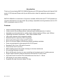
RKP21x-208KVM Series RKP241x-208KVM Series USER’S MANUAL WHERE TO BUY http://www.rackmountnet.com 1933 O'Toole Ave, #A107 San Jose, CA 95131, USA Toll Free Tel: (866)955-0598 email: [email protected] Introduction Thank you for purchasing RKP215-208KVM Rackmount LCD Keyboard Drawer with 8 ports KVM switch. LCD Keyboard Drawer with 8 ports KVM switch is ideal for application where space is critical. RKP215-208KVM is a combination of keyboard, trackball, KVM switch and TFT LCD packed into a drawer with features such as monitor flip up design, adjustable mounting brackets, built in LCD OSD, centralized control of 8 PCs. Features • • • • • • • • • • • • • • • • • • Unique mechanical design to maximize rack mountable space Unique monitor flip up design allows viewing through closed glass door of cabinet Adjustable mounting brackets for multiple depth cabinets between 650mm and 1000mm Lightweight aluminum construction – with a black anodize finish High quality keyboard with integrated trackball Keyboard options supporting twelve languages Side to side wide-angle viewing as CRT monitor Built in On Screen Display controlled by integral membrane switches Power saving feature for prolonging the life of LCD panel Standard D-sub 15-pin VGA input connector Front-access lock for security EMC shielding around the monitor housing to minimize interference All mounting hardware included Built in KVM switch function for easy controlling and monitoring up to 8 residing servers Support eight character password protection and search PC server name Auto scan mode for monitor PCs and flexible scan time from 5 ~ 99 sec LED display for easy status monitoring Supplied with eight screened cables 6 ft long Rev. JUL-02 Packing Contents RKP215-208KVM LCD Keyboard Drawer with KVM switch User’s manual AC to DC Power Adapter w/power cord Rack Mount Kit Standard 3-in-1 KVM cable 1 PCS 1 PCS 1 PCS 1 SET 8 PCS Before Unpacking It is very important to locate the LCD Keyboard Drawer with KVM switch in a suitable environment. z The surface for placing and fixing the LCD Keyboard Drawer with KVM switch should be stable and level or mounted into a suitable cabinet. z Make sure the place has good ventilation, is out of direct sunlight, sway from sources of excessive dust, dirt, heat, water, moisture and vibration. z Convenience for connecting the LCD Keyboard Drawer with KVM switch to the related facilities should be well considers too. Unpacking The LCD Keyboard Drawer with KVM switch comes with the following standard parts shown as below. Check and make sure they are included and in good condition. If anything is missing, or damage, contact the supplier immediately. Connection The DC Power inlet and connection cables are located in the lower rear panel of the LCD Keyboard Drawer. 1. DC Power Inlet f : plug in the AC to DC Power Adapter 2. VGA port : Connect to VGA port in computer 3. PS/2 Keyboard cable : Connect to keyboard port in computer 4. PS/2 Mouse cable : Connect to mouse port in computer Rev. JUL-02 Important Safeguards Please read all of these instructions carefully before you use the device. Save this manual for future reference. z Unplug the LCD Keyboard Drawer with KVM switch from the power outlet before cleaning. z Do not spray liquid cleaners or aerosol directly on the device. Wet a cloth with a neutral detergent (e.g. clean water) and squeeze it tight, then clean the screen slightly with it. z Do not expose the LCD Keyboard Drawer with KVM switch directly to rain, water, moisture or sunlight. z Avoid pressure on the LCD screen to prevent permanent damage to the display. z Do not attempt to service the device yourself. Improper operation may void your warranty. Refer all servicing to qualified service personnel. z Safe storage environment of the LCD Keyboard Drawer with KVM switch is ranging between –20oC and 60oC. Permanent damage could occur if the LCD Keyboard Drawer with KVM switch is stored outside the safe range. z Unplug the LCD Keyboard Drawer witch KVM switch immediately and call a qualified service personnel under the following conditions: 1. The VGA signal cord is frayed or damaged. 2. If the monitor has been exposed to rain, liquid or water. 3. If the monitor has been dropped or the casing has been damaged. What the warranty does not cover 1. Any product, on which the serial number has been defaced, modified or removed. 2. Damage, deterioration or malfunction resulting from: a) Accident, misuse, neglect, fire, water, lightning, or other acts of nature, unauthorized product modification, or failure to follow instructions supplied with the product. 3. b) Repair or attempted repair by anyone not authorized by us. c) Any damage of the product due to shipment. d) Removal or installation of the product. e) Causes external to the product, such as electric power fluctuation or failure. f) Use of supplies or parts not meeting our specifications. g) Normal wear and tear. h) Any other causes which does not relate to a product defect. Removal, installation, and set-up service charges. Rev. JUL-02 LCD Session Rev. JUL-02 On Screen Display - OSD OSD is the convenient way for a user to adjust the screen performance to his satisfaction. Menu / Selection Left Right 1. Entering the OSD Meun 2. Press the to display the OSD main menu. 3. Selecting icons for adjusting 4. Use buttons to scroll through the icons within the main menu and other sub-menus the currently selected icon will be highlighted. 5. A slider bar is displayed whenever a value is to be sent. Use the bar. 6. Saving the settings and Exit 7. Selections / selected values is automatically saved once made. Rev. JUL-02 buttons to scroll along 8. Select “Auto” for autoadjust LCD quality Rev. JUL-02 Customizing the Settings 1. Brightness • To perform brightness adjustment of the input RGB signal 2. Contrast • To adjust the contrast level of the input signal 3. Phase • To optimize the picture quality by adjusting the sampling clock of the input RGB Signal 4. Frequency • To adjust the frequency of the input signal to optimize the picture quality 5. H - Position • To adjust the horizontal position of the frame 6. V - Position • To adjust the vertical position of the frame 7. Sharpness • To enhance more sharpening on the appearance of images 8. Color Temperature • To enter into the Color temperature sub-menu Rev. JUL-02 1. H - Position • To adjust the horizontal position of the OSD frame 2. V - Position • To adjust the vertical position of the OSD frame 3. Half Tone • To switch the OSD color from full color to half tone 4. OSD Timeout • 1. To modify the duration of the OSD time-out Information • To display the existing input signal information 2. Reset • To reset the LCD to factory setting Rev. JUL-02 3. • Half Tone To switch LCD power ON/OFF auto mode Resolution Setting Step 1 – Press right click on the desktop Step 2 – Choose “Properties” Step 3 – change the “Screen Resolution” Rev. JUL-02 Step 4 – change the “Screen refresh rate” FAQ My display doesn’t work, even though the computer appears to work 1. Make sure the power cable is securely plugged into the display 2. Make sure the display is turned on 3. Try turning the display off and then turning it on again 4. Make sure the display’s power cord is plugged into a power outlet and into the AC power adapter. Check to see whether the outlet works by plugging another device into the outlet 5. Check the connection between the display and the computer, The cable connectors must be pushed in all the way The message “Check Cable” appears on my display 1. This message appears when the video cable is not properly connected to the computer 2. Make sure the analog video cable is plugged into the Analog Video Input port on the back of the display 3. Make sure the other end of analog video cable is plugged into the PC’s video port The message “No Sync” appears on my display 1. This message appears when there is no video signal from the computer a. with cable already connected 2. Make sure that the computer’s power is turn on 3. Make sure that your graphic card has its output already The message “Signal Out of Range” appears on my display 1. This message appears when the input signal is beyond the display’s capability 2. 13.3” 1024 x 768 at 70Hz (Max.) 3. 15.1” 1024 x 768 at 75Hz (Max.) 4. 17.1” 1280 x 1024 at 75Hz (Max.) Rev. JUL-02 FAQ – Sun Server Sun Server are using resolution at 1152 x 900 x 76Hz Supported resolution mode 640 x 480 x 70/75Hz 800 x 600 x 70/75Hz 1024 x 768 x 70/75Hz 1280 x 1024 x 75Hz (17” LCD) Note the Max. frequency of 13.3” is 70Hz You need to change the Sun Server resolution before you connect to LCD Display Please do the following procedure to change the resolution setting : 1. as root: you may find the following comment “/user/sbin/m64config” 2. Type “/user/sbin/m64config – prconf” to view current resolution 3. Type “/user/sbin/m64config – res 1024x768x70 now” to change to 1024x768 @ 70MHZ 4. the screen will be rubbish 5. Then type “pkill Xsun” 6. And Type “pkill Xsession” to restart the Xsession Remember this process need to RESTART the server Under Common Desktop Environment (CDE) To change the OpenBoot resolution, you can type the following commend in OK prompt 1. In OK prompt, type “setenv output-device screen:r1024x768x70” 2. Type “printenv” to confirm the resolution has been changed to 1024x768x70Hz 3. Then type “reset” to restart the system Remember this process need to RESTART the server Rev. JUL-02 Technical Information LCD Video Power Management Control Size 17” Screen Type TFT Active Matrix Display Area 337.92mm(H) x 270.336mm(V) Contrast Ratio 350 : 1 Viewing Angle 150{ (H) x 125{ (V) Typ. Resolution XGA 1280 x 1024 Pixel pitch 0.264mm (H) x 0.264mm (W) Response Time Tr=5ms, Tf=20ms Typ Brightness 250 cd/m2 Panel Color 16.7M Colors Back Light 4 Lamps Synchronization Horizontal : 31-69 KHz Range Vertical : 56-75 Hz Input Signal Analog RGB 0.7Vp-p VESA DPMS Power Micro on/off switch on the backside OSD Control Brightness, Contrast, Color, H position, V position, Auto config, OSD adjust, Dither, etc. External Connection Power Input Video Input LCD Size Screen Type Display Area Contrast Ratio Viewing Angle Resolution Pixel pitch Response Time Brightness Panel Color Back Light Video Power Management Control External Connection Rev. JUL-02 12V/5A DC adapter 15-pin D-Sub connector 15” TFT 304.1mm(H) x 228.1mm(V) 300 : 1 130{ (H) x 110{ (V) Typ 1024 x 768 0.297mm (H) x 0.297mm (W) Tr=5ms, Tf=20ms Typ 250 cd/m2 16.2M 4 CCFTs (Cold Cathode Fluorescent tube) Synchronization Horizontal : 48.36-60 KHz Range Vertical : 56-75 KHz Input Signal Analog RGB 0.7Vp-p VESA DPMS Power Micro on/off switch on the backside OSD Control Brightness, Contrast, Color, H position, V position, Clock, Phase, Auto config, Scaling, Input select, Clear EEPROM, Multi window, OSD adjust, Save Power Input Video Input 12V/5A DC adapter 15-pin D-Sub connector KVM Session Rev. JUL-02 KVM Bank Button Channel Button PS/2 Cable: Mini Din 6 pin Male to Male VGA Cable: HDB15 pin Male to Male Installation Before installation, please make sure all of peripherals and computers have been turned off. 1. Connect the Keyboard, VGA, Mouse cables to the computer ports of KVM switch 2. After Powering on computers and finishing the boot-up process, you can start to go KVM switch. Note: Please don’t switch the PC port (i.e. Don’t press the push button of KVM switch or run hot key) during the computers are under boot-up process. Rev. JUL-02 Startup 1. Power on the KVM power 2. 7 segments LED is on 3. Key-in the password, default is “00000000” 4. If you forget your password, please send back to Manufacturer / Distributor 5. Pressing to view all port 1 2 3 4 8 7 6 5 LED Indication When you change the channel If the PC is turn off or is disconnected The LED will flash otherwise is will lit Keyboard hot key command Simple key sequence Press “ Scroll Lock” twice within 2sec Follow with a beep sound, going into the hot key mode Need to key in the hot key within 2 sec Go back to Operation System Control state Rev. JUL-02 Hot Key Press “Bank” & “Channel” at the same time to reset the KVM switch to default setting • S.L. + S.L. + Previous Channel • S.L. + S.L. + Next Channel Note: You also could press “up arrow key” or “down arrow key” longer time to speed up selecting the destination port • S.L. + S.L. + Page Up Previous Bank • S.L. + S.L. + Page Down Next Bank To Select PC port • S.L. + S.L. + Bank No. + Port No. • Bank No. 1 – 8 (Max.) Port No. 01 – 16 (Max.) • Example we select Bank 3 Channel 14 • S.L. + S.L. + 3 + 14 • Example we select Bank 7 Channel 5 • S.L. + S.L. + 7 + 05 Beeper On/Off • S.L. + S.L. + B (Default is On) Auto Scan • S.L. + S.L. + S (Default is 10 sec from P to P) • Press any key to stop ROM REFLASH Rom Refresh • S.L. + S.L. + R (Refresh to OSD Default Value) • Not include the PASSWORD Find by PC name • S.L. + S.L. +F FIND:█ • Key the PC name • Search PC name starting from 1st PC port OSD Menu • S.L. + S.L. + Spacebar Rev. JUL-02 Rev. JUL-02 OSD Menu Bank No. BANK : 1 01 SYSTEM 01 02 SYSTEM 02 ( 03 SYSTEM 03 04 SYSTEM 04 05 SYSTEM 05 06 07 SYSTEM 07 08 SYSTEM 08 SYSTEM 06 PC Name List OSD : 1 0 SEC. CHANGE PASSWORD SCAN: 1 0 SEC. CONSOLE ON/OFF ESC : QUIT TAB : NEXT KVM Settings ENTER :COMPLETE INSERT :EDIT Ç/È: SELECT PORT Info. PgDn/PgUp: BANK SELECT Use “Tab” key to select items like Bank, OSD, SCAN, CHANGE PASSWORD, CONSOLE ON/OFF, etc… Use Page Up & Page Down to switch previous or next bank Rev. JUL-02 OSD Menu BANK : 1 01 SYSTEM 01 02 SYSTEM 02 ( 03 SYSTEM 03 04 SYSTEM 04 05 SYSTEM 05 06 07 SYSTEM 07 08 SYSTEM 08 SYSTEM 06 OSD : 1 0 SEC. CHANGE PASSWORD SCAN: 1 0 SEC. CONSOLE ON/OFF • PC Name List • “” near to the PC name represents the PC system is powered on • Use up arrow key “Ç” or down arrow key “È” to select port for destination PC name and press “Enter” to select • Edit PC name • Press “Ins” key for editing PC name • PC name should not more than 8 characters • After finish edit press “Enter” • OSD – 10 sec Ç/È: SELECT PORT • OSD window display or PC name exist 10 sec • Default Value is 10 sec • Modify from 05 – 99 sec PgDn/PgUp: BANK SELECT • Scan – 10 sec ESC : QUIT TAB : NEXT ENTER :COMPLETE INSERT :EDIT • Scan interval from one PC port to next PC port is 10 sec • Default Value is 10 sec • Max. 99 sec Rev. JUL-02 OSD - Password ENTER PASSWORD : █ ESC : QUIT ENTER : ENTER NEW PASSWORD : █ ESC : QUIT ENTER : COMPLETE • Changing Password • • • • • • Default password “00000000” Choose “Change Password” Key-in the existing password Enter the New Password Re-Enter the New Password Changing Password complete • Max. 8 digits RETYPE NEW PASSWORD : █ ESC : QUIT ENTER : COMPLETE NEW PASSWORD COMPLETE ESC : QUIT ENTER : COMPLETE Console On/OFF ON – any user can the console OFF – user is not allow to use the console, unless key-in password Default – OFF, you need to key-in password Escape 102 ?SYSTEM 02 PC name show in the up-left corner Press “Esc” key to dear the message right away of OSD menu Rev. JUL-02 Rev. JUL-02 Cascade Using 3 in 1 KVM cable connect from Bank 1’s “Cascade port” to Bank 2’s “Console port”. After connected please press “Bank” & “Channel” button on the front of the KVM switch to reset the KVM switch. Bank 1 Bank 2 Bank 3 Bank 8 (Max) Cascade level Max. 8 level Max. PC connection is 128 (all using 16 ports) All KVM switch is compatible & can cascade with each other Using 3 in 1 KVM cable to cascade Normal distance from one KVM to another is 15ft Rev. JUL-02 FAQ 1. Don’t press any keys on the keyboard while the selected computer is booting up. Otherwise, it might cause the keyboard error or keyboard is not detected at PC side. 2. The computer boot up fine, but keyboard doesn’t work z Make sure the keyboard works when directly plugged into the computer. z Try a different keyboard, but use only 101, 102 or 104-key keyboard. 3. The Mouse is not detected during PC boot up. z Make sure the mouse works when directly plugged into the computer. z Make sure the mouse is a true PS/2 mouse. A combo mouse will work just as long as it is set for PS/2 mode with the correct adapter. Try a different mouse. z Avoiding moving the mouse or pressing the mouse buttons when switching ports. z Avoiding switching ports during shutting down the PC process. z When you switch one PC port to another PC port, the best scan time setting need to be set to 5 sec. or more. Normally, the VGA monitor change one resolution mode to another will take one or two seconds. So, the scan time is not recommended to below 5 seconds. 4. Sun Server connection problem KVM switch are using standard PS/2 type keyboard and mouse and D-sub 15pin VGA for connection. If you need to connect Sun Server to KVM switch, you need a separate converter kit. Sun – 21 Kit Convert Sun Micro Din 8 pin Keyboard & Mouse to Standard Din 6 pin P/S 2 Keyboard & Mouse Convert Sun micro 13W3 VGA to D-sub 15 pin Standard VGA For old model Sun Micro Server Sun – 31 Kit Convert USB to P/S 2 Keyboard & Mouse New model Sun Micro Server are using D-sub 15 pin Standard VGA Rev. JUL-02 Technical Information 8 Ports KVM Switch PC Port PC Port Connector (All Female Type) 8 PC selection 7 segment LED On Screen Display Control Scan Intervals Keyboard Emulation Mouse Emulation VGA Resolution Bandwidth Daisy Chain MAX Level MAX PC Connection Housing Power Adapter Operation Temperature PS/2 Keyboard mini Din 6 pin PS/2 Mouse Mini Din 6 pin VGA HDDB 15pin PS/2 Keyboard mini Din 6 pin PS/2 Mouse Mini Din 6 pin VGA HDDB 15pin On Screen Display Manual, Hot Key, Push Button One Bank LED, Two PC Port LEDs Yes 5~99 Sec. PS2 PS2 1920X1440 200MHz 8 levels 120 Metal DC 12V 1A or DC 9V 1A 0~40℃ Storage Temperature -20 ~ 60℃ Humidity Size 0~80%, Non-Condensing 19” Rack Mount / 1RU Daisy Chain Port Connector (All Female Type) Rev. JUL-02