1
CS50/Z
2002
5RW1-AE1
SERVICE MANUAL
EAS00001
CS50/Z
SERVICE MANUAL
© 2002 by Yamaha Motor España, S.A.
1st Edition, September 2002
Any reprinting or use of this material
without the prior authorisation of
Yamaha Motor España, S.A.
is expressly prohibited.
Printed in Spain.
EAS00002
NOTICE
This manual was produced by the Yamaha Motor España, S.A., primarily for use by Yamaha/MBK
dealers and their qualified mechanics. It is not possible to include all the knowledge of a mechanic
in one manual. Therefore, anyone who uses this book to perform maintenance and repairs on
Yamaha/MBK vehicles should have a basic understanding of the mechanics and the techniques to
repair these types of vehicles. Repair and maintenance work attempted by anyone without this
knowledge is likely to render the vehicle unsafe and unfit for use.
Yamaha Motor España, S.A., is continually striving to improve all of its models. Modifications and
significant changes in specifications or procedures will be forwarded to all authorized Yamaha/MBK
dealers and will appear in future editions of this manual where applicabe.
NOTE:
Designs and specifications are subject to change without notice.
EAS00005
IMPORTANT INFORMATION
Particularly important information is distinguished in this manual by the following.
The Safety Alert Symbol means ATTENTION! BECOME ALERT!
YOUR SAFETY IS INVOLDED!
t
s WARNING
Failure to follow WARNING instructions could result in severe injury
or death to the scooter operator, a bystander, or a person inspecting or repairing the scooter.
CAUTION:
A CAUTION indicates special precautions that must be taken to
avoid damage to the scooter.
NOTE :
A NOTE provides key information to make procedures easier or clearer.
EAS00007
HOW TO USE THIS MANUAL
FORMAT OF THIS MANUAL
This manual consists of chapters for the main subject categories (See “Illustrated Symbols”).
First heading : This is a chapter with a symbol at the top right-hand side of each page.
Second heading :
This title appears at the top of each page to the left of the chapter symbol.
(For the “Inspection and periodic adjustments”, chapter the third heading
appears.)
Third heading : This is a final heading.
MANUAL FORMAT
All the procedures in this manual are organized sequentially, step by step. The information has been
compiled to make reading easy for the mechanic and to provide useful reference material which
contains ample explanations of all disassembly, repair, assembly and inspection procedures. A particularly important procedure is placed between a lines of asterisks “**” with each procedure preceded by “•”.
IMPORTANT CHARACTERISTICS
• Data and special tools are put in a box preceded by a corresponding symbol .
• A number within a circle indicates the number of a part, and a alphabetical letter within a circle indicates data or an alignment mark , everything else is indicated by a letter within a box .
• The conditions of defective components will precede an arrow symbol and the course of action
to be followd will follow the symbol .
DETAILED DIAGRAM
Each chapter provides detailed diagrams before each disassembly section, for the easy identification of disassembly/assembly procedures.
EAS00008
GEN
INFO
ILLUSTRATED SYMBOLS
(See illustration)
The symbols from to are designed as
thumb indices, to indicate the chapter number and index.
SPEC
CHK
ADJ
ENG
COOL
CARB
CHAS
ELEC
10
The illustrated symbols from 10 to 16 are
used to identify the specifications that appear
in the text.
TRBL
SHTG
11
12
13
14
15
16
10 Refill liquid
11 Lubricant
12 Special tool
13 Torque
14 Wear, play limit
15 Motor speed
16 Ω, V, A
17 to 24 of the
The illustrated symbols from detailed diagrams indicate the grade of lubricant and the site of the lubrication point.
17
18
19
20
21
22
23
General information
Specifications
Periodic checks and adjustments
General motor revision
Cooling system
Carburetor
Chassis
Electrical system
Troubleshooting
24
New
17 Apply motor oil
18 Apply gear oil
19 Apply molybdenum disulphide oil
20 Apply wheel bearing grease
21 Apply lightweight lithium soap base
grease
22 Apply molybdenum disulphide grease
23 Apply blocking agent (LOCTITE®)
24 Use a new one
EAS00010
TABLE OF CONTENTS
GENERAL INFORMATION
SPECIFICATIONS
PERIODIC CHECKS AND
ADJUSTMENTS
ENGINE
COOLING SYSTEM
CARBURETOR
CHASSIS
ELECTRICAL SYSTEM
TROUBLESHOOTING
GEN
INFO
1
SPEC
2
CHK
ADJ
3
ENG
4
COOL
5
CARB
6
CHAS
7
ELEC
8
TRBL
SHTG
9
GEN
INFO
1
GEN
INFO
CHAPTER 1
GENERAL INFORMATION
SCOOTER IDENTIFICATION……………………………………………………1-1
FRAME SERIAL NUMBER ……………………………………………………1-1
ENGINE SERIAL NUMBER……………………………………………………1-1
IMPORTANT INFORMATION …………………………………………………1-2
REPLACEMENT PARTS ………………………………………………………1-2
GASKETS, OIL SEALS AND O-RINGS ……………………………………1-2
LOCK WASHERS/PLATES AND COTTER PINS……………………………1-2
BEARINGS AND OIL SEALS …………………………………………………1-2
CIRCLIPS ………………………………………………………………………1-3
SPECIAL TOOLS …………………………………………………………………1-4
IDENTIFICATION OF SCOOTER
GEN
INFO
EAS00015
GENERAL INFORMATION
SCOOTER IDENTIFICATION
FRAME SERIAL NUMBER
The frame serial number is stamped on the
chassis.
ENGINE SERIAL NUMBER
The serial number of the engine is stamped
on the raised portion of the rear left section of
the transmission box.
NOTE:
The first three digits of these numbers are for
identifying the model; the remaining digits
constitute the production number of the unit.
NOTE:
Designs and specifications are subject to
change without notice.
1-1
IMPORTANT INFORMATION
GEN
INFO
IMPORTANT INFORMATION
EAS00021
REPLACEMENT PARTS
1. Use only genuine Yamaha/MBK parts for all
replacements. Use the oil and/or grease
recommended by Yamaha/MBK for
assembly and adjustment.
EAS00022
GASKETS, OIL SEALS AND O-RINGS
1. Replace all gaskets, seals and O-rings
when overhauling the engine. All gasket
surfaces, oil seal lips and O-rings must be
cleaned.
2. Properly oil all mating parts and bearings
during reassembly. Apply grease to the oil
seal lips.
EAS00023
LOCK WASHERS/PLATES AND COTTER
PINS
1. Replace all lock washers/plates and cotter pins after removal. Bend lock tabs along
the bolt or nut flats after the bolt or nut has
been tightened to specification.
EAS00024
BEARINGS AND OIL SEALS
1. Install the bearings and oil stops with
their manufacturer brands or numbers
facing outwards. (In other words, the stamped letters should be on the side exposed
to view.) When installing oil seals, apply a
light coating of lightweight lithium base grease to the seal lips. Put oil on the bearings
when installing.
CAUTION:
Do not use compressed air to spin the bearings dry. This will damage the bearing surface.
1-2
IMPORTANT INFORMATION
GEN
INFO
EAS00025
CIRCLIPS
1. Check all circlips carefully before reassembly. Always replace piston pin clips
after one use. Replace distorted circlips.
When installing a circlip , make sure that
the sharp-edged corner is positioned
opposite the thrust it receives. See sectional view.
Shaft.
1-3
SPECIAL TOOLS
GEN
INFO
EAS00027
SPECIAL TOOLS
The following special tools are necessary for complete and accurate tune-up and assembly. Use
only the appropriate special tools; this will help prevent damage caused by the use of inappropriate tools or improvised techniques.
When placing an order, refer to the list provided below to avoid any mistakes.
Tool No.
Tool name / Usage
Illustration
90890-01235
Rotor holding tool
90890-01337
This tool is used to remove the flywheel
magneto.
Clutch spring bracket
90890-01362
This tool is used to remove the clutch nut
while holding the compression spring.
Container of the crankshaft installer a
Bolt of the crankshaft installer b
Adapter c, Spacer d
These tools are used to install the
crankshaft.
Flywheel puller
90890-01135
For removing the flywheel.
Crankcase separation tool
90890-01384
This tool is used to remove the
crankshaft or separate the crankcase.
Oil seal guide
90890-01403
Protects the edge of the oil seal during
the installation of the secondary sliding
pulley wheel.
Ring nut wrench
90890-01701
This tool is used to loosen and tighten
the steering ring nut.
Pulley bracket
90890-03079
This tools is used to disassemble and
assemble the secondary pulley.
Thickenss gauge
90890-01274
-01275
-01277
-01288
.
This tool is used to measure the clearance.
1-4
SPECIAL TOOLS
Tool No.
Tool name / Usage
Illustration
90890-03112
Pocket tester
90890-03113
This instrument is very important
for checking the electrical system.
Engine tachometer
90890-01409
This tool is necessary for detecting
the engine rpm.
Oil seals guide
90890-01410
This tool is used to install the left oil
guide of the crankcase.
Oil seals installer
90890-06754
This tool is used to install the left oil
seal of the crankcase.
Ignition checker
90890-85505
This instrument is necessary
to check the components of the
ignition system.
Yamaha bond No. 1215
90890-01348
This bond (sealant) is used for crankcase
mating surface, etc.
Locknut wrench
90890-01367 -01400 90890-01326
90890-01294
GEN
INFO
This tool is used to loosen and tighten
the secondary sheave nut.
Front oil seals inserter
Counterweight a
Adapter b
These tools are used in the installation
of seals.
T-handle
Damper rod holder
These tool are used for holding the damper rod
holder when removing or installing the damper
rod holder.
1-5
SPEC
2
SPEC
CHAPTER 2
SPECIFICATIONS
GENERAL SPECIFICATIONS …………………………………………………2-1
MAINTENANCE SPECIFICATIONS ……………………………………………2-3
ENGINE …………………………………………………………………………2-3
CHASSIS ………………………………………………………………………2-5
ELECTRICAL SYSTEM ………………………………………………………2-6
CONVERSION TABLE……………………………………………………………2-7
GENERAL TIGHTENING TORQUE SPECIFICATIONS ……………………2-7
TIGHTENING TORQUES ………………………………………………………2-8
ENGINE TIGHTENING TORQUES …………………………………………2-8
CHASSIS TIGHTENING TORQUES …………………………………………2-9
COOLING SYSTEM (CS50Z only) ……………………………………………2-10
CABLE ROUTING ………………………………………………………………2-11
GENERAL SPECIFICATIONS
SPEC
SPECIFICATIONS
GENERAL SPECIFICATIONS
Model
Dimensions:
Overall lenght
Overall widht
Overall height
Seat height
Wheelbase
Minimum ground clearance
Basic weight (With oil and full fuel tank):
Engine:
Engine type
Cylinder arrangement
Displacement
Bore x stroke
Compression ratio
Starting system
Lubrication system:
Oil type or grade:
Engine oil
Transmission oil
Oil capacity:
Oil tank (motor oil)
Transmission fluid
Periodic fluid change
Total amount
Cooling system capacity:
(Total amount)
Air filter:
Fuel:
Type
Fuel tank capacity
Carburetor:
Type/quantity
Manufacturer
Spark plug:
Type/Manufacturer
Spark plug gap
Clutch type:
Transmission:
Primary reduction system
Primary reduction ratio
Secondary reduction system
Secondary reduction ratio
Transmission type
Operation
CS50
1.740 mm
675 mm
1.065 mm
770 mm / 776 mm
1.210 mm
132 mm
80,5 kg
CS50Z
83,7 kg
Plate valve, gasoline, 2-strokes
air-cooled
Liquid cooled
Forward-inclined single cylinder
49,3 cc
40,0 x 39,2 mm
10,2 : 1
11,4 : 1
Electric and kickstarter
Yamaha autolube
2-strokes motor oil (JASO grade FC)
SE type 10W30 SAE motor oil
1,4 L
0,10 L
0,11 L
–
Wet type element
0,910 L
Unleaded gasoline
5,5 L
PHVA12ZS/1, PY12/1
DELL’ORTO, GURTNER
PHVA12ZS/1
DELL’ORTO
BR8HS/N.G.K.
0,6 ~ 0,7 mm
Dry, centrifugal automatic
Helical gear
52/13 (4.000)
Straight gearing
42/13 (3.230)
43/13 (3.310)
Single speed automatic
(V-belt type)
Centrifugal automatic type
2-1
GENERAL SPECIFICATIONS
Model
Chassis:
Frame type
Front axle incline angle
Steering angle base
Tire:
Size/Type (Front)
Size/Type (Rear)
Tire pressure (cold tire):
Front
Rear
Maximum Load:
Front
Rear
Brake:
Type of front brake
Activation
Type of rear brake
Activation
Suspension:
Front suspension
Rear suspension
Shock absorber:
Front shock absorber
Rear shock absorber
Wheel travel:
Front wheel travel
Rear wheel travel
Electrical:
Ignition system
Generator system
Battery type or model
Battery capacity
Type of headlamp:
Bulb wattage/quantity:
Headlight
Tail/brake light
Turn signal light
Auxiliary light
License plate light
Meter lighting
Indicator light voltage/quantity:
Oil level warning light
Turn signal indicator light
High beam indicator light
Coolant temperature warning light
CS50
SPEC
CS50Z
Steel tube underbone
25°
80 mm
110/70-12 / 47 L
120/70-12 / 51 L, 130/70-12 / 56 L
175 KPa
200 KPa
(1,75 kg/cm2)
(2,00 kg/cm2)
175 KPa
225 KPa
(1,75 Kg/cm2)
(2,25 Kg/cm2)
Disk brake
Right hand operation
Drum brake
Left hand operation
Telescopic fork
Unit swing
Coil spring/Oil damper
Coil spring/Oil damper
70 mm
60 mm
DC-CDI
Magnetic flywheel
Maintenance free
12V 4AH
Bulb
12V,
12V,
12V,
12V,
12V,
12V,
35W / 35Wx1
5W / 21Wx1
10Wx2 (rear) / 12V, 16Wx2 (front)
5W x 2
5W x 1
1,2W x 2
LED
12V, 2W x 2
12V, 2W x 1
–
2-2
LED
MAINTENANCE SPECIFICATIONS
SPEC
MAINTENANCE SPECIFICATIONS
ENGINE
Model
Cylinder head:
Warp limit
Cylinder:
Bore size
<Limit>
Taper limit
Out of round limit
Piston:
Piston size
Measuring point
Piston clearance
On measurement
1st
Piston rings:
Cut-away section (BXT)/TYPE
Top ring
2nd ring
End gap (installed)
Top ring
2nd ring
<Limit>
Sice clearance
Top ring
2nd ring
Crankshaft:
Crank width “A”
Runout limit “C”
Large end of rod side clearance “D”
Small end of rod clerance “F”
CS50
CS50Z
0,02 mm
* The lines indicate measurement
with straight edge
39,993 ~ 40,012 mm
<40,1 mm>
0,05 mm
0,01 mm
39,952 - 39,972 mm
5 mm
39,957 - 39,997 mm
0,034 - 0,047 mm
0,029 - 0,042 mm
40,25 mm
1.5 x 1.8 mm/Keystone
1.5 x 1.8 mm/Keystone
0,15 ~ 0,35 mm
0,15 ~ 0,35 mm
<0,6 mm>
0,03 ~ 0,05 mm
0,03 ~ 0,05 mm
37,90 ~ 37,95 mm
0,03 mm
0,2 ~ 0,5 mm
0,4 ~ 0,8 mm
2-3
MAINTENANCE SPECIFICATIONS
Model
Automatic centrifugal clutch:
Clutch shoe thickness
<Limit>
Clutch shoe spring free length
Clutch - in revolution
Clutch - stall revolution
2,0 mm
<1,0 mm>
29,9 mm
3.350 - 3.850 r/min.
5.200 - 6.000 r/min.
V-belt:
V-belt width
<Limit>
16,5 mm
<15,7 mm>
Transmission:
Main axle eccentricity limit
Drive axle eccentricity limit
0,08 mm
0,08 mm
Pedal starting:
Type
Strength of pedal spring
Ratchet
150 ~ 250 g
Air filter oil grade:
Carburetor:
Type / Manufacturer / Amount
Main jet / Model
(M.J.)
Jet needle
(J.N.)
Main air jet
(M.A.J.)
Pilot jet
(P.J.)
Pilot screw
(P.A.S.)
Valve seat size
Engine idling speed
Starter jet
CS50
SPEC
CS50Z
3.950 - 4.450 r/min.
6.900 - 7.700 r/min.
For foam air filter or air-cooled 2-stroke
motor oil
PHVA12ZS/1
DELL’ORTO
#65
A20-3/5
ø 2.5
#36
2 - 21/4
1.2
#50
2-4
PY12/1
PHVA12ZS/1
GURTNER DELL’ORTO
#62
#65
B10A-2/3
A35-4/5
ø 2.0
ø 2.5
#38
#36
13/4 - 2
13/4 ± 1/8
1.4
1.2
1650 ~ 1950 r/min
#42
#50
MAINTENANCE SPECIFICATIONS
SPEC
CHASSIS
Model
Steering system:
Steering bearing type Upper
Lower
Ball bearing
Ball bearing
Front suspension:
Front fork travel
Fork spring free length
70 mm
224 mm
Spring rate
(K1)
(K2)
Oil capacity
Oil grade
Rear suspension:
Shock absorber stroke
Spring free length
Spring rate
(K1)
(K2)
Wheels:
Type of front wheel
Type of rear wheel
Size/material of front tyre
Size/material of rear tyre
Rim runout limit
Radial
Lateral
CS50
1,33 Kgf/mm
2,0 Kgf/mm
45 cc ± 1
Fork oil: 10W or equivalent
60 mm
220 mm
4,58 Kgf/mm
6,12 Kgf/mm
Alloy rim
Alloy rim
2,75 x 12 / aluminium
3,00 x 12 / aluminium
1,0 mm
1,0 mm
Front disc brake:
Type
Disc outside diameter x thickness
Pad thickness
<Limit>
Interior diameter of pump
Calliper interior diameter
Brake fluid type
Single
ø 190 x 3,5 mm
4,5 mm
<0,5 mm>
11 mm
30 mm
DOT #4
Rear drum brake:
Type
Drum inside diameter
<Limit>
Shoe thickness
<Limit>
Single cam
ø 110 mm
<ø 110,5 mm>
4 mm
<2 mm>
Brake levers:
Free play of the front brake lever
(right)/measurement
Free play of the rear brake lever
(left)/measurement
2 ~ 5 mm / At the end of the lever
5 ~ 10 mm / At the end of the lever
2-5
CS50Z
MAINTENANCE SPECIFICATIONS
SPEC
ELECTRICAL SYSTEM
Model
Ignition system:
Type
Ignition timing (B.T.D.C.)
Pickup coil resistance (colour)
Igntion coil:
Minimum spark gap
Primary winding resistance
Secondary winding resistance
Charging system:
Normal output
Source coil resistance (colour)
Lighting system:
Lighting output
Lighting coil resistance (colour)
CS50
CS50Z
DC-CDI
14°/5.000 r/min
400 ~ 600 Ω at 20 °C (68 °F)
(Black-White/Blue)
6.0 mm
0.56 ~ 0.84 Ω at 20 °C
5.68 ~ 8.52 KΩ at 20 °C
0.4 A or more/3.000 r/min
1.0 A or less/8.000 r/min
0.288 ~ 0.432 Ω at 20 °C (68 °F) (White-Black)
12 V or more/3.000 r/min
15 V or less/8.000 r/min
0.176 ~ 0.264 Ω at 20 °C (68 °F)
(Yellow/Red-Black)
Battery:
Type
Capacity
GT4L-BS
12V 4 Ah
Electric starter system:
Type
Constant mesh type
Starter motor:
Output
Armature coil resistance
Brush length
<Limit>
0.14 kw
0.064 ~ 0.079 Ω at 20 °C (68°F)
3.9 mm
<0.9 mm>
Circuit breaker:
Type
Amperage/Quantity
Fuse
7.5A x 1
2-6
CONVERSION TABLE /
GENERAL TIGHTENING TORQUES SPECIFICATIONS
SPEC
EAS00028
EAS00029
CONVERSION TABLE
GENERAL TIGHTENING TORQUE
SPECIFICATIONS
All specification data in this manual are listed
in SI and METRIC UNITS.
Use this table to convert METRIC unit data to
IMPERIAL unit data.
This chart specifies tightening torques for
standard fasteners with a standard ISO thread
pitch. Tightening torque specifications for
special components or assemblies are provided for each chapter of this manual. To avoid
warpage, tighten multi-fastener assemblies in
a crisscross pattern and progressive stages
until the specified tightening torque is
reached. Unless otherwise specified, tightening torque specifications require clean, dry
threads. Components should be at room
temperature.
Ex.
METRIC
MULTIPLIER
IMPERIAL
** mm x
0.03937 =
** in
2 mm x
0.03937 = 0.08 in
CONVERSION TABLE
METRIC TO IMPERIAL
Metric unit
m•kg
m•kg
cm•kg
cm•kg
Multiplier
7.233
86.794
0.0723
0.8679
Imperial unit
ft•lb
in•lb
ft•lb
in•lb
Weight
kg
g
2.205
0.03527
lb
oz
Speed
km/h
0.6214
mi/h
Distance
km
m
m
cm
mm
0.6214
3.281
1.094
0.3937
0.03937
mi
ft
yd
in
in
Volume,
Capacity
cc (cm3)
cc (cm3)
L (liter)
L (liter)
0.03527
0.06102
0.8799
0.2199
oz (IMP liq.)
cu•in
qt (IMP liq.)
gal (IMP liq.)
kg/mm
kg/cm2
Centigrade
(°C)
55.997
14.2234
9/5 + 32
lb/in
psi (lb/in2)
Fahrenheit (°F)
Tightening
Torque
Misc.
A: Width across flats
B: Thread diameter
A
(Nut)
10
12
14
17
19
22
2-7
mm
mm
mm
mm
mm
mm
B
(Bolt)
6 mm
8 mm
10 mm
12 mm
14 mm
16 mm
General tightening
torques
Nm
m • kg
6
0.6
15
1.5
30
3.0
55
5.5
85
8.5
130
13.0
TIGHTENING TORQUES
SPEC
TIGHTENING TORQUES
ENGINE TIGHTENING TORQUES
Part to be tightened
Spark plug
Cylinder head and cylinder
Cylinder
Air protector 2 (A/C)
Air protector 3 (A/C)
Fan (A/C)
Automatic lubrication pump
Reed valve
Air filter
Carburettor cover
Exhaust pipe
Muffler
Exhaust pipe protector
Exhaust pipe cover
Crankcase
Cover of crankcase 2
Cover of crankcase 1
Air conduct (A/C)
Crankcase bracket
Drain bolt
Oil plug
Intermediate gear plate
Kickstarter
Starter motor
Clutch housing
Primary pulley
Magnet base
Magnet rotor
Cranckshaft oil seal stay
Water pump housing cover (L/C)
Water pump driver bolts (L/C)
Magnet cover (L/C)
Part name
Thread
size
–
Nut
Stud
Screw
Screw
Screw
Screw
Bolt
Screw
Screw
Screw
Bolt
Bolt
Bolt
Bolt
Bolt
Bolt
Screw
Screw
Bolt
Plug
Screw
Bolt
Bolt
Nut
Nut
Screw
Nut
Bolt
Bolt
Bolt
Bolt
M 14
M7
M7
M6
M6
M6
M5
M6
M6
M4
M6
M8
M6
M6
M6
M6
M6
M6
M6
M8
M 14
M6
M6
M6
M 10
M 12
M6
M 12
M6
M6
M6
M6
2-8
Q’ty
1
4
4
3
1
3
2
4
1
2
2
2
2
5
6
6
12
2
2
1
1
2
1
2
1
1
2
1
1
3
3
3
Tightening
torque
Remarks
Nm
m•kg
20
14
17
7
2
7
4
11
9
2
9
26
0.7
0.7
10
10
12
7
7
18
3
8
9
13
40
45
8
43
8
7
6.5
6.5
2,0
1.4
1.7
0.7
0.2
0.7
0.4
1.1
0.9
0.2
0.9
2.6
0.7
0.7
1.0
1.0
1.2
0.7
0.7
1.8
0.3
0.8
0.9
1.3
4.0
4.5
0.8
4.3
0.8
0.7
0.65
0.65
TIGHTENING TORQUES
SPEC
CHASSIS TIGHTENING TORQUES
Part to be tightened
Frame, Engine and Parts
Frame with bracket 3
Engine bracket 3 with
the engine
Cushion and related parts
Rear shock absorber
(bracket side)
Rear shock absorber
(engine side)
Forks, handlebar and parts
Handlebar or grip with
axle guide
Axle guide
Brake tube joint screw
Seats and related parts
Seat lock unit
Hook bracket
Case
Covers and related parts
Plastic parts, plastic covers
Frame footrest plate
Leg protector 2/frame
Front and rear wheels
Front wheel axle
Rear wheel axle
Rear brake lever
Shoe axle
Brake disk
Front brake calliper
Fuel tank
Fuel cut-off valve
Thread size
Tihtening
torque
Nm
m•kg
M10 x 1.25
42
4.2
M12 x 1.25
84
8.4
M10 x 1.25
31.5
3.15
M8 x 1.25
17.5
1.75
M10 x 1.25
42.5
4.25
M25 x 1.00
75
7.5
M10 x 1.25
23
2.3
M6 x 1.0
M6 x 1.0
M6 x 1.0
9.75
8
8
0.975
0.8
0.8
M5
M6 x 1.0
M6 x 1.0
1.5
4
4
0.15
0.4
0.4
M10 x 1.25
M14 x 1.5
M6 x 1.0
M10 x 1.25
M8 x 1.25
M8 x 1.25
47.5
125
13.5
12
23
23
4.75
12.5
1.35
1.2
2.3
2.3
11
1.1
2-9
Remarks
See chapter 3
“ADJUSTING THE
STEERING HEAD”
COOLING SYSTEM
COOLING SYSTEM (L/C VERSION ONLY)
Radiator
Water pump
Cylinder
Reservoir tank
2-10
SPEC
CABLE ROUTING
SPEC
CABLE ROUTING
A Insert the three tubes through the clamp
B Connect the oil hose to the carburettor
C Set the intake hose under the reinforcement
Front brake hose
Rear brake cable
Front brake calliper
Front mudguard
Taillight
Vacuum pipe
Fuel pipe
Intake hose (L/C)
Wire harness
10 Engine breather
11 Throttle cable
12 Seat lock cable
13 Coolant hose (L/C)
14 DC-CDI
15 Coolant hoses - Carburetor (L/C)
(L/C)
D Clamp the fuel pipe to the carburettor
E Tighten together the ground cable and the
starter motor
F Clamp all the cables except the coolant
hose (L/C) without tightening
G Clamp the intake hose to the air filter box
(L/C)
H Pass the brake cable through the guide
2-11
CABLE ROUTING
SPEC
CABLE ROUTING
A Clamp the wire harness, brake cable and
Rectifier / Regulator
Main switch
Fuel level gauge
Horn
Ignition coil
Spark plug wire
Oil level gauge
Oil tank
Speedometer cable
throttle to the frame
B Clamp the oil hose to the tank
C Connect the oil hose to the pump
D Tie both ends
E Tighten together the ground cable and the
ignition coil
F Pass the speedometer cable through the
guide
G Insert the seat lock cable throught the orifice of the frame
2-12
CABLE ROUTING
SPEC
CABLE ROUTING
A Throttle tension cable. Cover then adjust
B Connect the brake switch cables in this
Front brake switch
Wire harness
Throttle cable
Rear brake cable
Front brake hose
area
C Do not pass the brake hose through
the clamp
2-13
CHK
ADJ
3
CHK
ADJ
CHAPTER 3
PERIODIC CHECKS AND ADJUSTMENTS
INTRODUCTION/PERIODIC MAINTENANCE/LUBRICATION INTERVALS……3-1
REAR BODYWORK AND MUDGUARD ………………………………………3-2
REMOVAL ………………………………………………………………………3-2
INSTALLATION …………………………………………………………………3-3
FRONT COWLING AND FOOTREST …………………………………………3-4
REMOVAL ………………………………………………………………………3-4
INSTALLATION …………………………………………………………………3-5
HANDLEBAR COVERS …………………………………………………………3-6
REMOVAL ………………………………………………………………………3-6
INSTALLATION …………………………………………………………………3-7
ENGINE ……………………………………………………………………………3-8
ADJUSTING THE ENGINE IDLING SPEED …………………………………3-8
ADJUSTING THE THROTTLE CABLE FREE PLAY ………………………3-9
CHECKING THE SPARK PLUG ……………………………………………3-10
CHECKING THE ENGINE OIL LEVEL ……………………………………3-11
CHANGING THE TRANSMISSION OIL ……………………………………3-12
AUTOLUBE PUMP AIR BLEEDING ………………………………………3-12
CLEANING THE AIR FILTER ELEMENT……………………………………3-13
CHECKING THE COOLANT LEVEL (CS50Z only) ………………………3-14
CHANGING THE COOLANT (CS50Z only) ………………………………3-15
CHASSIS …………………………………………………………………………3-18
ADJUSTMENT THE FRONT BRAKE LEVER………………………………3-18
ADJUSTMENT THE REAR BRAKE LEVER ………………………………3-18
CHECKING THE FRONT BRAKE PADS …………………………………3-18
CHECKING THE REAR BRAKE SHOES …………………………………3-19
CHECKING THE BRAKE FLUID LEVEL……………………………………3-19
BLEEDING THE HYDRAULIC BRAKE SYSTEM …………………………3-20
CHECKING AND ADJUSTING THE STEERING HEAD …………………3-21
CHECKING THE TIRES ……………………………………………………3-23
CHECKING THE WHEELS …………………………………………………3-23
CHECKING THE FRONT FORK ……………………………………………3-23
REAR SHOCK ABSORBER INSPECTION…………………………………3-24
ELECTRICAL SYSTEM…………………………………………………………3-25
CHECKING AND CHARGING THE BATTERY ……………………………3-25
CHECKING THE FUSE ………………………………………………………3-30
REPLACING THE HEADLIGHT BULB ……………………………………3-31
ADJUSTING THE HEADLIGHT BEAM ……………………………………3-31
INTRODUCTION/PERIODIC MAINTENANCE/
LUBRICATION INTERVALS
CHK
ADJ
EAS00036
PERIODIC CHECKS AND ADJUSTMENTS
INTRODUCTION
This chapter includes all the information necessary to perform the recommended inspections and
adjustments. These preventive maintenance procedures, if followed correctly, will ensure more reliable operation of the vehicle and a longer life of service. The need for costly revision and repair work
will be greatly reduced. This information is applicable to vehicles that are already in service, as well
as for new vehicles that have been prepared for sale. All service technicians must become familiar
with the entire chapter.
EAS00037
PERIODIC MAINTENANCE AND LUBRICATION INTERVALS
ODOMETER READING
( x 1.000 km)
No.
ITEM
CHECK OR MAINTENANCE JOB
Fuel line
• Check fuel hoses and vacuum hose
for cracks.
2
Spark Plug
• Check condition.
• Clean and regap.
3
Air filter element
• Clean.
• Replace.
• Check operation, fluid level and vehicle for
fluid leakage.
1
*
1
6
12
√
√
4
*
Front brake
5
*
Rear brake
√
√
Brake hose
√
√
√
• Replace.
*
Wheels
• Check runout and for damage.
8
*
Tires
•
•
•
•
Check tread depth and for damage.
Replace if necessary.
Check air pressure.
Correct if necessary.
*
Wheel
bearings
• Check bearing for looseness or damage.
10
*
Steering bearings
• Check bearing play and steering for roughness.
12
√
√
√
√
√
√
√
√
√
√
√
√
√
√
√
√
√
√
√
√
√
√
√
√
√
√
√
√
√
√
√
√
√
• Lubricate with lithium-soap-based grease.
*
√
Every 4 years
9
11
√
Whenever worn to the limit
• Check for cracks or damage.
7
√
√
Whenever worn to the limit
• Check operation and adjust brake lever freeplay.
• Replace brake shoes.
*
24
√
√
• Replace brake pads.
6
18
√
• Replace.
ANNUAL
CHECK
Every 24.000 km
Chassis fasteners
• Make sure that all nuts, bolts and screws are
properly tightened.
√
√
√
√
√
Centerstand
• Check operation.
• Lubricate.
√
√
√
√
√
13
*
Front fork
• Check operation and for oil leakage.
√
√
√
√
14
*
Rear shock
absorber assembly
• Check operation and shock absorber for oil
leakage.
√
√
√
√
15
*
Carburetor
• Check starter (choke) operation.
• Adjust engine idling speed.
√
√
√
√
√
√
16
*
Autolube pump
• Check operation.
• Bleed if necessary.
√
√
√
17
*
Cooling system
• Check coolant level and vehicle for coolant leakage.
√
√
(L/C version only)
• Change.
Final transmission
• Check vehicle for oil leakage.
√
oil
• Change.
√
V-belt
• Replace.
Front and rear
brake switches
• Check operation.
Moving parts
and cables
• Lubricate.
Lights, signals
and switches
• Check operation.
• Adjust headlight beam.
18
19
*
20
21
22
*
√
√
√
√
Every 3 years
√
√
*: It is recommended that these items be revised by an authorized Yamaha/MBK dealer.
**: Apply grease for mid-weight bearings.
NOTE:
• The air filter needs more frequent service if you are riding in unusually wet or dusty areas.
• Hydraulic brake service
•• Regularly check and, if necessary, correct the brake fluid level.
•• Replace the brake hoses every four years and if cracked or damaged.
3-1
√
√
√
√
√
√
√
√
√
√
√
√
√
√
√
√
√
√
√
√
√
REAR BODYWORK, MUDGUARD
CHK
ADJ
REAR BODYWORK, MUDGUARD
REMOVAL
1. Remove:
• seat 2. Remove:
• central panel NOTE:
Slide the panel to the front.
3. Remove:
• rear fender 4. Remove:
• oil tank cap and grommet
• fuel tank cap and grommet
• passenger hand grap bolts and collars • passenger hand grap oil
3-2
REAR BODYWORK, MUDGUARD
CHK
ADJ
5. Remove:
• side covers (4 bolts)
NOTE:
Remove carefully the hook between side cover
and tail light.
6. Remove:
• battery cover , leads and battery
• oil tank fixing bolt
NOTE:
Fix the oil tank to the frame with a band.
• helmet box
7. Remove:
• rear mudguard (4 bolts)
INSTALLATION
Reverse the removal process.
NOTE:
After installing all plastic parts, check that all
hooks are properly attached.
3-3
FRONT COWLING AND FOOTREST
CHK
ADJ
FRONT COWLING AND
FOOTREST
REMOVAL
1. Remove:
• front upper cowling
NOTE:
Disconect front light and indicator light couplers.
2. Remove:
• front middle cowling
3. Remove:
• lower cowling
4. Remove:
• under cowling
3-4
FRONT COWLING AND FOOTREST
CHK
ADJ
5. Remove:
• legshield
NOTE:
Remove first the main switch cover
6. Remove:
• hook bracket 7. Remove:
• footrest
INSTALLATION
Reverse the removal process
NOTE:
After installing all plastic parts, check that all
hooks are properly attached.
3-5
HANDLEBAR COVERS
CHK
ADJ
HANDLEBAR COVERS
REMOVAL
1. Remove:
• upper handlebar cover NOTE:
Disconect panel meter couplers
2. Remove:
• front master cylinder (2 bolts) • handlebar switch couplers
• stop switch couplers
• rear brake wire from lever side
• throttle wire from throttle grip
3. Remove:
• handlebar fixing bolt 4. Remove:
• lower handlebar cover bolts
3-6
HANDLEBAR COVERS
CHK
ADJ
5. Slide dow the lower handlebar cover 6. Remove the wiring harness rubber band from the handlebar
7. Remove:
• handlebar
• lower handlebar cover
INSTALLATION
Reverse the removal process.
NOTE:
• For handlebar installation refer to chapter 7.
• After installing all plastic parts, check that
all hooks are properly attached.
3-7
CHK
ADJ
ADJUSTING THE ENGINE IDLING SPEED
ENGINE
EAS00054
ADJUSTING THE ENGINE IDLING SPEED
NOTE:
Prior to adjusting the engine idling speed, the
air filter element should be clean, and the engine shoud have adequate compression.
1. Start the engine and let it warm up for several minutes.
2. Connect:
• engine tachometer (onto the spark plug lead)
Engine tachometer
90890-03113
3. Check:
• engine idling speed
Out of specification
Adjust.
Engine idling speed
1.650 ~ 1.950 r/min
4. Adjust:
• engine idling speed
a. Remove the center panel.
b. Turn the pilot air screw in or out until it is
lightly seated.
c. Turn the pilot screw out the specified number of turns.
a
b
Pilot air screw setting
CS50:
Dellorto 2 - 2 1/4
Gurtner 1 3/4 - 2
CS50Z: Dellorto 1 3/4 ± 1/8
d. Turn the throttle stop screw in direction
a or b until the specified engine idling
speed is obtained.
Direction a
Engine idling speed is
increased.
Direction b
Engine idling speed is
decreased.
e. Install the center panel.
5. Adjust:
• throttle cable free play
Refer to “ADJUSTING THE THROTTLE
CABLE FREE PLAY“
3-8
Throttle cable free play (at the
flange of the throttle grip)
2 ~ 5 mm
ADJUSTING THE THROTTLE CABLE FREE PLAY
CHK
ADJ
EAS00058
ADJUSTING THE THROTTLE CABLE FREE
PLAY
NOTE:
Prior to adjusting the throttle cable free play,
the engine idling speed should be adjusted.
1. Check:
• throttle cable free play a
Out of specification Adjust.
Throttle cable free play (at the
flange of the throttle grip)
2 ~ 5 mm
2. Remove:
• center panel
• grip bar
• battery
• right side cover
• helmet box
Refer to BODYWORK
3. Adjust:
• throttle cable free play
a
b
Carburetor side
a. Loosen the locknut .
b. Turn the adjusting nut in direction a or
b until the specified throttle cable free play
is obtained.
Direction a
Direction b
Throttle cable free play
is increased.
Throttle cable free play
is decreased.
c. Tighten the locknut.
NOTE:
If the specified throttle cable free play cannot
be obtained on the carburetor side of the cable,
use the adjusting nut on the handlebar side.
Handlebar side
a. Loosen the locknut .
b. Turn the adjusting nut in direction
a or b
until the specified throttle cable freey play is
obtained.
Direction a
Direction b
b
a
Throttle cable free play
is increased.
Throttle cable free play
is decreased.
c. Thighten the loknut.
s WARNING
After adjusting the throttle cable free play,
start the engine and turn the handlebar to
the right or left to ensure that this does not
3-9 cause the engine idling speed to change.
CHK
ADJ
CHECKING THE SPARK PLUG
EAS00060
CHECKING THE SPARK PLUG
1. Disconnect:
• spark plug cap
2. Remove:
• spark plug
CAUTION:
Before removing the spark plug, blow away
any dirt accumulated in the spark plug well
with compressed air to prevent it from
falling into the cylinder.
3. Check:
• spark plug type
Incorrect Change.
Spark plug type (manufacturer)
BR8HS (NGK)
4. Check:
• electrode Damage/wear Replace the spark plug.
• insulator Abnormal color Replace the spark plug.
Normal color is medium-to light tan.
5. Clean:
• spark plug
(with a spark plug cleaner or wire brush)
6. Measure:
• spark plug gap a
(with a wire Thickness gauge)
Out of specification Regap.
Spark plug type (manufacturer)
0,6 ~ 0,7 mm
7. Install:
• spark plug
20 Nm (2.0 m • kg)
NOTE:
Before installing the spark plug, clean the
spark plug and gasket surface.
8. Connect:
• spark plug cap
3-10
CHECKING THE ENGINE OIL LEVEL
CHK
ADJ
CHECKING THE ENGINE OIL LEVEL
1. Inspect:
• engine oil level
Low oil level Add sufficient oil.
Oil indicator light “OIL CAUTION”
Visual inspection steps for engine oil level
Place main switch in
position (h)
The “OIL CAUTION”
indicator light is not lit.
The “OIL CAUTION”
indicator light is lit.
Place the main switch in
position “f”
Inspect for defective
electric circuit, bulbs,
etc.
The “OIL CAUTION”
indicator light is not lit.
The “OIL CAUTION”
indicator light is lit.
The engine oil level and
electric circuit are in
good condition.
Supply engine oil.
The “OIL CAUTION”
indicator light is lit.
Recommended oil:
YAMAHA 2T 2-stroke engine oil
or equivalent
Total:
1.4 L
NOTE:
After filling the oil tank, close it with the cap and close the seat.
3-11
CHANGING THE TRANSMISSION OIL/
AUTOLUBE PUMP AIR BLEEDING
CHANGING THE TRANSMISSION OIL
1. Remove:
• drain bolt Drain the transmission oil.
• oil filler cap 2. Inspect:
• gasket (drain bolt)
• o-ring (filler cap)
Damaged Replace
3. Install:
• gasket
• drain bolt
2
4
CHK
ADJ
Drain bolt
18 Nm (1.8 m • kg)
4. Fill:
• transmission case
Transmission oil:
10W30 type SE or higher engine
oil or GL gear oil
Capacity:
0,11 L
CS50
AUTOLUBE PUMP AIR BLEEDING
The air bleeding must be done always the oil
tank is empty, when the intake lube is disconnected or the tank is disassembled.
NOTE:
The air bleeding must be done after filling the
oil tank.
1. Remove
• fan cover (CS50)
• crankcase cover (right) (CS50Z)
CS50Z
2. Remove
• drain screw Let the oil flow out until the air bubbles have
been removed.
3-12
CHK
ADJ
CLEANING THE AIR FILTER ELEMENT
EAS00089
CLEANING THE AIR FILTER ELEMENT
Carburetor side
1. Remove:
• center cover
• grip bar
• battery
• right side cover
• helmet box
• air filter box assembly 2. Remove:
• air filter box cover
• air filter
CAUTION:
Never start up the engine with the air filter
removed. This will allow the entry of unfiltered air, causing rapid wear and possible
damage to the engine. Also, using the engine without the filter will affect the carburettor jets resulting in poor performance and
the possible overheating of the engine.
Be careful not to block the inlet area of the
air filter with cloths or rags.
3. Inspect:
• damaged element
4. Clean:
• air filter
Change
Steps for cleaning air filter:
• Wash the filter carefully but completely with
solvent.
s WARNING
Never use solvents with a low flammability
point, such as petrol, to clean the filter.
Such solvents may cause fire or explosions.
• Clean off excess solvent from the filter and
leave it to dry.
CAUTION:
Do not twist the air filter element when
squeezing it.
• Apply oil for foam air filters or YAMAHA 2T
engine oil or equivalent oil for 2 stroke engines.
• Wipe off the excess oil.
NOTE:
The filter should be wet but not dripping.
3-13
CHECKING THE COOLANT LEVEL
CHK
ADJ
EAS00103
CHECKING THE COOLANT LEVEL (CS50Z
only)
1. Stand the scooter on a level surface.
NOTE:
• Place the scooter on a suitable stand.
• Make sure the scooter is upright.
40
c
30
20
10
0
2. Check:
• coolant level
The coolant level should be between the
maximum level mark a and minimum level
mark b
Below the minimum level mark Remove
the front upper cowling and add the recommended coolant to the proper level.
50
60
d
70
80
j
y
z
a
k
b
a
b
CAUTION:
• Adding water instead of coolant lowers
the antifreeze content of the coolant. If
water is used instead of coolant check,
and if necessary, correct the antifreeze
concentration of the coolant.
• Use only distilled water. However, if distilled water is not available, soft water
may be used.
3. Start the engine, warm it up for several
minutes, and then turn it off.
4. Check:
• coolant level
NOTE:
Before checking the coolant level, wait a few
minutes until it settles.
3-14
CHANGING THE COOLANT
CHK
ADJ
EAS00105
CHANGING THE COOLANT (CS50Z only)
1. Remove:
• water pump cover • coolant filler cap
s WARNING
Do not remove the water pump cover when
the engine is hot. Scalding hot fluid and
steam may be blown out, which could
cause serious injury. When the engine has
cooled, remove the water pump cover.
2. Drain:
• coolant
(from the engine and radiator)
3. Check:
• o-ring (water pump cover)
Damage Replace
4. Install:
• water pump cover
7 Nm (0.7 m • kg)
5. Fill:
• coolant reservoir
(with the specified amount of the recommended coolant)
NOTE:
While start the engine, fill the coolant until specified amount.
Recommended antifreeze
High-quality ethylene glycol antifreeze containing corrosion inhibitors for aluminum engines
Mixing ratio
1:1 (antifreeze: water)
Quantity
Total amount
0,910 L
Coolant reservoir capacity
0,380 L
3-15
CHANGING THE COOLANT
CHK
ADJ
Handling notes for coolant
Coolant is potentially harmful and should be
handled with special care.
s WARNING
• If coolant splashes in your eyes, thoroughly wash them with water and consult a doctor.
• If coolant splashes on your clothes,
quickly wash it away with water and then
with soap and water.
• If coolant is swallowed, induce vomiting
and get immediate medical attention.
CAUTION:
• Adding water instead of coolant lowers
the antifreeze content of the coolant. If
water is used instead of coolant check,
and if necessary, correct the antifreeze
concentration of the coolant.
• Use only distilled water. However, if distilled water is not available, soft water
may be used.
• If coolant comes into contact with painted surfaces, immediately wash them
with water.
• Do not mix different types of antifreeze.
3-16
CHANGING THE COOLANT
CHK
ADJ
6. Install:
• coolant filler cap
7. Warm it up for several minutes, and then
stop it.
8. Check:
• coolant level
Refer to “CHECKING THE COOLANT
LEVEL”.
NOTE:
Before checking the coolant level, wait a few
minutes until the coolant has settled.
NOTE:
For a quick air bleeding, lift up the front wheel
1metre with the engine at idle speed.
This will provide a effective and air quick bleeding from the head cylinder to the radiator.
9. Install
• front upper cowling
3-17
ADJUSTMENT THE FRONT BRAKE LEVER/
ADJUSTMEN THE REAR BRAKE LEVER/
CHECKING THE FRONT BRAKE PADS
CHK
ADJ
EAS00109
CHASSIS
a
ADJUSTMENT THE FRONT BRAKE LEVER
1. Check:
• free play of the front brake lever a.
Brake lever free play (at the end of
the brake lever)
2 ~ 5 mm
s WARNING
The soft or spongy feeling of the brake lever
may indicate the presence of air in the
brake system. This air should be extracted
by bleeding the brake system before using
the vehicle. Air in the system will reduce the
braking capacity and may cause loss of
control and accidents. Inspect and bleed
the system if it is necessary.
EAS00114
ADJUSTMENT THE REAR BRAKE LEVER
1. Check.
• free play of rear brake lever a
Outside specified value Adjust
a
Brake lever free play (at the end of
the brake lever)
5 ~ 10 mm
j
k
Steps for adjusting the free play of the rear
brake lever:
• Turn the adjuster inwards or outwards
until the correct free play is obtained.
EAS00117
CHECKING THE FRONT BRAKE PADS
1. Inspect:
• brake pads.
Wear indicator almost contacts with the
brake disc . Replace the set of brake
pads.
See “CHANGE OF BRAKE PADS” section
in chapter 7.
3-18
CHECKING THE REAR BRAKE SHOES/
CHECKING THE BRAKE FLUID LEVEL
CHK
ADJ
EAS00126
CHECKING THE REAR BRAKE SHOES
1. Activate the brake lever
2. Check:
• wear indicator Indicator on wear limit line Replace
the brake shoes.
EAS00116
CHECKING THE BRAKE FLUID LEVEL
NOTE:
Place the scooter upright when inspecting the
fluid level.
1. Check:
• brake fluid level.
The brake fluid level is below the minimum
level line Refill up to correct level.
MIN
Recommended fluid:
DOT #4
CAUTION:
The fluid may corrode painted surfaces or
plastic parts. Always clean any spilt fluid
immediately.
s WARNING
• Only use fluid of the designated quality.
Otherwise the rubber seals may deteriorate due to leakages and poor performance of the brakes.
• Refill with the same type of fluid. The mixture of fluids may cause a damaging chemical reaction which may cause the poor
performance of the brakes.
• Take care not to let water enter the pump
while it is being filled. The water will lower
the boiling point of the fluid significantly
and may cause a steam blockage.
3-19
BLEEDING THE HYDRAULIC BRAKE SYSTEM
CHK
ADJ
EAS00133
BLEEDING THE HYDRAULIC BRAKE
SYSTEM
s WARNING
Bleed the hydraulic brake system whenever:
• the system is disassembled.
• a brake hose is loosened, disconnected
or replace.
• the brake fluid level is very low.
• brake operation is faulty.
NOTE:
• Be careful not to spill any brake fluid or
allow the brake master cylinder reservoir to
overflow.
• When bleeding the hydraulic brake system,
make sure there is always enough brake
fluid before applying the brake. Ignoring this
precaution could allow air to enter the
hydraulic brake system, considerably lengthening the bleeding procedure.
• If bleeding is difficult, it may be necessary
to let the brake fluid settle for a few hours.
Repeat the bleeding procedure when the
tiny bubbles in the hose have disappeared.
1. Bleed:
• brake fluid
Steps for air bleeding:
a. Add the appropriate amount of brake fluid
to the sump.
b. Install the diaphragm. Take care not to spill
fluid or to let the sump overflow.
c. Connect the clean plastic tube .
d. Place the other end of the tube in a container.
e. Slowly apply the brake lever several times.
f. Pull the lever inwards. Keep it in this position.
g. Loosen the bleed screw and tighten the
lever as far as it will go.
h. Tighten the bleed screw when it has reached its limit, afterwards loosen the lever.
i. Repeat steps (e) to (h) until the air bubbles
in the system have been removed.
j. Add brake fluid to the correct level.
WARNING
After bleeding the hydraulic brake system, check the brake operation.
3-20
CHECKING AND ADJUSTING THE STEERING HEAD
CHK
ADJ
EAS00148
CHECKING AND ADJUSTING THE
STEERING HEAD
1. Stand the scooter on a level surface.
s WARNING
Securely support the scooter so that there
is no danger of it falling over.
NOTE:
Place the scooter on a suitable stand so that
the front wheel is elevated.
2. Check:
• steering head
Grasp the bottom of the front fork legs and
gently rock the front fork.
Blinding/looseness Adjust the steering
head.
3. Remove:
• front upper cowling
• front middle cowling
• legshield
4. Adjust:
• steering head
a. Remove the upper ring nut , the lock
washer , the center ring nut and the
rubber washer .
b. Loosen the lower ring nut and then tighten it to specification with the ring nut
wrench.
c. Loosen the lower ring nut 1/2 turn counterclockwise then tighten it to specification
with a steering nut wrench.
Lower ring nut (initial tightening
torque)
38 Nm (3.8 m • kg)
s WARNING
Do not overtighten the lower ring nut.
3-21
CHECKING AND ADJUSTING THE STEERING HEAD
CHK
ADJ
Lower ring nut (final tightening torque)
6.5 Nm (0.65 m • kg)
d. Check the steering head for looseness or
binding by turning the front fork all the way
in both directions. If any binding is felt,
remove the lower bracket and check the
upper and lower bearings.
Refer to “STEERING HEAD” in chapter 7.
e. Install the rubber washer.
f. Install the center ring nut.
g. Finger tighten the center ring nut , then
align the slots of both ring nuts. If necessary, hold the lower ring nut and tighten the
center ring nut until their slots are aligned.
h. Install the lock washer .
b
NOTE:
a
Make sure the lock washer tabs a sit correctly
in the ring nut slots b.
i. Hold the lower and center ring nuts with a
ring nut wrench and tighten the upper ring
nut with a steering nut wrench.
Steering/Ring nut wrench
90890-01403
Upper ring nut
75Nm (7.5 m • kg)
5. Install:
• legshield
• front middle cowling
• front upper cowling
3-22
CHECKING THE TIRES / CHECKING THE WHEELS/
CHECKING THE FRONT FORK
CHK
ADJ
EAS00163
CHECKING THE TIRES
1. Measure:
• air pressure
Outside specified value
Maximum load*:
Pressure cold
Up to 90 kg
90 kg to
maximum load
Adjust
158.3 kg (CS50Z)
161.5 kg (CS50)
Front
Rear
175kpa.
200kpa.
(1.75kg/cm2)
(2.0kg/cm2)
175kpa.
225kpa.
(1.75kg/cm2)
(2.25kg/cm2)
* Total weight of rider, passenger, cargo and
accessories
2. Inspect:
• tyre surface
Worn/Damaged
Change
Minimum depth of thread of tyres
0.8 mm
Thread depth
Side wall
Wear indicator
EAS00168
CHECKING THE WHEELS
The following procedure applies to both of the
wheels.
1. Check:
• wheel
Damage/out-of-round Replace.
s WARNING
Never attempt to make any repairs to the
wheel.
NOTE:
After a tire or wheel has been changed or
replaced, always balance the wheel.
EAS00151
CHECKING THE FRONT FORK
1. Inspect:
• front fork
Bent/Damaged Fork bar Change
Oil leaks Seals Replace
Rough operation Fork assembly Replace
3-23
REAR SHOCK ABSORBER INSPECTION
CHK
ADJ
REAR SHOCK ABSORBER INSPECTION
1. Inspect:
• rear shock absorber
Oil leaks/Damage Replace
2. Check
• tightening torque
3-24
Upper
(nut)
31.5 Nm (3.15 m • kg)
Lower
(bolt)
17.5 Nm (1.75 m • kg)
CHECKING AND CHARGING THE BATTERY
CHK
ADJ
EAS00179
ELECTRICAL SYSTEM
CHECKING AND CHARGING THE BATTERY
s WARNING
Batteries generate explosive hydrogen gas
and contain electrolyte which is made of
poisonous and highly caustic sulfuric acid.
Therefore, always follow these preventive
measures:
• Wear protective eye gear when handling
or working near batteries.
• Charge batteries in a well-ventilated
area.
• Keep batteries away from fire, sparks or
open flames (e.g., welding equipment,
lighted cigarettes).
• DO NOT SMOKE when charging or handling batteries.
• KEEP BATTERIES AND ELECTROLYTE
OUT OF REACH OF CHILDREN.
• Avoid bodily contact with electrolyte as it
can cause severe burns or permanent
eye injury.
FIRST AID IN CASE OF BODILY CONTACT:
EXTERNAL
• Skin — Wash with water.
• Eyes — Flush with water for 15 minutes
and get immediate medical attention.
INTERNAL
• Drink large quantities of water or milk
followed with milk of magnesia, beaten
egg or vegetable oil. Get immediate
medical attention.
CAUTION:
• This is a sealed battery. Never remove
the sealing caps because the balance
between cells will not be maintained and
battery performance will deteriorate.
• Charging time, charging amperage and
charging voltage for an MF battery are
different from those of conventional batteries. The MF battery should be charged
as explained in the charging method
illustrations. If the battery is overcharged, the electrolyte level will drop considerably. Therefore, take special care
when charging the battery.
3-25
CHK
ADJ
CHECKING AND CHARGING THE BATTERY
NOTE:
Since MF batteries are sealed, it is not possible to check the charge state of the battery by
measuring the specific gravity of the electrolyte. Therefore, the charge of the battery has to
be checked by measuring the voltage at the
battery terminals.
1. Remove:
• battery cover
2. Disconnect:
• battery leads
(from the battery terminals)
CAUTION:
First, disconnect the negative battery lead
, and then the positive battery lead .
3. Remove:
• battery
4. Check:
• battery charge
a. Connect a pocket tester to the battery terminals.
Positive tester probe
positive battery
terminal
Negative tester probe negative battery
terminal
NOTE:
• The charge state of an MF battery can be
checked by measuring its open-circuit voltage (i.e., the voltage when the positive terminal is disconnected).
• No charging is necessary when the opencircuit voltage equals or exceeds 12.8 V.
b. Check the charge of the battery, as shown
in the charts and the following example.
Example
c. Open-circuit voltage = 12.0 V
d. Charging time = 6.5 hours
e. Charge of the battery = 20 ~ 30%
3-26
CHECKING AND CHARGING THE BATTERY
CHK
ADJ
5. Charge:
• battery
(refer to the appropriate charging method
illustration)
s WARNING
Do not quick charge a battery.
CAUTION:
• Never remove the MF battery sealing
caps.
• Do not use a high-rate battery charger
since it forces a high-amperage current
into the battery quickly and can cause
battery overheating and battery plate
damage.
• If it is impossible to regulate the charging current on the battery charger, be
careful not to overcharge the battery.
• When charging a battery, be sure to
remove it from the scooter. (If charging
has to be done with the battery mounted
on the scooter, disconnect the negative
battery lead from the battery terminal.)
• To reduce the chance of sparks, do not
plug in the battery charger until the battery charger leads are connected to the
battery.
• Before removing the battery charger lead
clips from the battery terminals, be sure
to turn off the battery charger.
• Make sure the battery charger lead clips
are in full contact with the battery terminal and that they are not shorted. A
corroded battery charger lead clip may
generate heat in the contact area and a
weak clip spring may cause sparks.
• If the battery becomes hot to the touch
at any time during the charging process,
disconnect the battery charger and let
the battery cool before reconnecting it.
Hot batteries can explode!
• As shown in the following illustration, the
open-circuit voltage of an MF battery
stabilizes about 30 minutes after charging has been completed. Therefore,
wait 30 minutes after charging is completed before measuring the open-circuit
voltage.
3-27
CHECKING AND CHARGING THE BATTERY
CHK
ADJ
Charging method using a variable-current (voltage) charger
Measure the open-circuit
voltage prior to charging.
NOTE:
Voltage should be measured 30 minutes after the
machine is stopped.
Connect a charged and
AMP meter to the battery
and start charging.
YES
NOTE:
Set the charging voltage at 16 ~ 17 V. (If the setting is lower, charging will be insufficient. If too
high, the battery will be over-charged.)
Make sure that the current
is higher than the standard
charging current written on
the battery.
NO
By turning the charging
voltage adjust dial, set the
charging voltage at 20 ~ 24 V.
Adjust the voltage so that the
current is at the standard
charging level.
YES
Monitor the amperage for
3 ~ 5 minutes to check if the
standard charging current is
reached.
NO
Set the time according to the
charging time suitable for the
open-circuit voltage.
Refer to “Battery condition
checking steps.
If the current does not
exceed the standard
charging current after 5
minutes, replace the battery.
If charging requires more than 5 hours, it is advisable to check the
charging current after a lapse of 5 hours. If there is any change in the
amperage, readjust the voltage to obtain the standard charging
current.
Measure the battery open-circuit voltage after leaving the battery
unused for more than 30 minutes.
12.8 V or more --- Charging is complete.
12.7 V or less --- Recharging is required.
Under 12.0 V --- Replace the battery
3-28
CHECKING AND CHARGING THE BATTERY
CHK
ADJ
Charging method using a constant voltage charger
Measure the open-circuit
voltage prior to charging.
NOTE:
Voltage should be measured 30 minutes after the
machine is stopped.
Connect a charged and
AMP meter to the battery
and start charging.
YES
Make sure that the current
is higher than the standard
charging current written on
the battery.
Charge the battery until the
battery’s charging voltage
is 15 V.
NO
This type of battery charger
cannot charge the MF battery.
A variable voltage charger is
recommended.
NOTE:
Set the charging time at 20 hours
(maximum).
Measure the battery open-circuit
voltage after leaving the battery
unused for more than 30 minutes.
12.8 V or more --- Charging is complete.
12.7 V or less --- Recharging is required.
Under 12.0 V --- Replace the battery.
3-29
CHECKING AND CHARGING THE BATTERY/
CHECKING THE FUSE
CHK
ADJ
6. Install:
• battery
7. Connect:
• battery leads
(to the battery terminals)
CAUTION:
First, connect the positive battery lead ,
and then the negative battery lead .
8. Check:
• battery terminals
Dirt Clean with a wire brush.
Loose connection Connect properly.
9. Lubricate:
• battery terminals
Recommended lubricant
Dielectric grease
10. Install:
• battery cover
EAS00181
CHECKING THE FUSE
1. Remove:
• the battery cover
See the “FRONT BODYWORK” section
2. Inspect:
• fuse Defective Replace
Steps to be taken for blown fuses:
• Disconnect the ignition and circuit.
• Install a new fuse of the correct amperage.
• Connect the switches to check the correct
operation of the electrical device.
• If the fuse blows immediately after, check the
circuit concerned.
s WARNING
Do not use fuses of a higher amperage
than that recommended. This can
cause extensive damage to the electrical system and fire.
Description
Principal
3-30
Amperage
Quantity
7.5 A
1
REPLACING THE HEADLIGHT BULB/
ADJUSTING THE HEADLIGHT BEAM
CHK
ADJ
EAS00182
REPLACING THE HEADLIGHT BULB
1. Remove:
• front upper cowling
2. Remove:
• headlight bulb holder 3. Remove:
• headlight bulb
B Y G
s WARNING
Since the headlight bulb gets extremely hot,
keep flammable products and your hands
away from the bulb until it has cooled
down.
4. Install:
• headlight bulb NEW
Secure the new headlight bulb with the
headlight bulb holder.
CAUTION:
Avoid touching the glass part of the headlight bulb to keep it free from oil, otherwise
the transparency of the glass, the life of the
bulb and the luminous flux will be adversely
affected. If the headlight bulb gets soiled,
thoroughly clean it with a cloth moistened
with alcohol or lacquer thinner.
5. Install:
• headlight bulb holder
6. Install:
• front upper cowling
EAS00186
ADJUSTING THE HEADLIGHT BEAM
1. Adjust:
• headlight beam (vertically)
a. Turn the adjusting screw in direction a
or b.
b
a
Direction a
Headlight beam is
raised.
Direction b
Headlight beam is
lowered.
3-31
ENG
4
ENG
CHAPTER 4
ENGINE
ENGINE REMOVAL ………………………………………………………………4-1
COVER REMOVAL ……………………………………………………………4-1
COOLING SYSTEM (CS50Z only)……………………………………………4-1
CABLES, LEADS AND HOSES ………………………………………………4-1
ENGINE REMOVAL ……………………………………………………………4-2
ENGINE DISASSEMBLY…………………………………………………………4-3
REMOVING THE REAR WHEEL ……………………………………………4-3
REMOVING THE CYLINDER HEAD AND CYLINDER ……………………4-3
REMOVING THE PISTON PIN AND PISTON ………………………………4-3
REMOVING THE KICKSTARTER SYSTEM …………………………………4-4
REMOVING THE PRIMARY SHEAVE ………………………………………4-5
DISASSEMBLING THE SECONDARY SHEAVE ……………………………4-6
REMOVING THE STARTER SYSTEM ………………………………………4-7
TRANSMISSION ………………………………………………………………4-7
DC-CDI MAGNETO ……………………………………………………………4-8
AUTOLUBE OIL PUMP ………………………………………………………4-9
REMOVING THE CENTERSTAND……………………………………………4-9
DISASSEMBLING THE CRANKCASE AND CRANKSHAFT………………4-9
INSPECTION AND REPAIR ……………………………………………………4-11
CHECKING THE CYLINDER HEAD ………………………………………4-11
CHECKING THE CYLINDER AND PISTON ………………………………4-12
CHECKING THE PISTON RINGS …………………………………………4-14
CHECKING THE PISTON PIN AND PISTON PIN BEARING ……………4-15
CHECKING THE KICKSTARTER ……………………………………………4-16
TRANSMISSION………………………………………………………………4-16
AUTOLUBE OIL PUMP………………………………………………………4-17
CHECKING THE CRANKSHAFT ……………………………………………4-17
CHECKING THE BEARINGS ………………………………………………4-18
CHECKING THE PRIMARY SHEAVE ………………………………………4-18
CHECKING THE SECONDARY SHEAVE …………………………………4-19
CHECKING THE V-BELT ……………………………………………………4-20
STARTER CLUTCH AND GEARS …………………………………………4-21
ENGINE ASSEMBLY AND ADJUSTMENT …………………………………4-22
CRANKSHAFT AND CRANKCASE…………………………………………4-22
INSTALLING THE CRANKSHAF ……………………………………………4-23
AUTOLUBE OIL PUMP AND DC-CDI MAGNETO ………………………4-24
INSTALLING THE AUTOLUBE OIL PUMP ………………………………4-25
INSTALLING THE DC-CDI MAGNETO ……………………………………4-25
TRANSMISSION………………………………………………………………4-27
INSTALLING THE TRANSMISSION ………………………………………4-28
STARTER SYSTEM …………………………………………………………4-29
INSTALLING THE STARTER SYSTEM ……………………………………4-30
PRIMARY AND SECONDARY SHEAVE ……………………………………4-31
KICKSTARTER ………………………………………………………………4-32
ASSEMBLING THE SECONDARY SHEAVE ………………………………4-33
ASSEMBLING THE PRIMARY SHEAVE……………………………………4-34
INSTALLING THE KICKSTARTER …………………………………………4-36
PISTON, CYLINDER AND CYLINDER HEAD (CS50) ……………………4-37
PISTON, CYLINDER AND CYLINDER HEAD (CS50Z) …………………4-38
PISTON AND PISTON PIN …………………………………………………4-39
CYLINDER AND CYLINDER HEAD ………………………………………4-39
ENGINE REMOUNTING ……………………………………………………4-41
ENGINE REMOVAL
ENG
ENGINE
ENGINE REMOVAL
COVER REMOVAL
1. Remove:
• center cover
• helmet box
Refer to “REAR BODYWORK, MUDGUARD” in chapter 3.
COOLING SYSTEM (CS50Z only)
1. Disconnect:
• coolant hose (on water pump cover)
Drain the coolant
• coolant hose (on cylinder head)
CABLES, LEADS AND HOSES
1. Loosen:
• rear axle nut
2. Disconnect:
• rear brake cable
3. Disconnect:
• starter motor leads (positive/negative leads)
4. Disconnect:
• DC-CDI magneto lead
• spark plug cap
• temperature sensor lead on the cylinder
head
• autochoke lead • throttle cable (with throttle valve) • vaccum hose • fuel hose 5. Disconnect:
• oil hose delivery (oil tank-oil pump)
4-1
ENGINE REMOVAL
ENG
ENGINE REMOVAL
1. Place a suitable stand under the frame.
2. Remove:
• rear shock absorber bolt (lower) • engine mounting bolt 3. Remove:
• engine
NOTE:
Lift up the frame and remove the engine.
4. Place the frame on a suitable stand.
4-2
ENGINE DISASSEMBLY
ENG
ENGINE DISASSEMBLY
REMOVING THE REAR WHEEL
1. Remove:
• rear wheel
Refer to “REMOVING THE REAR WHEEL”
in chapter 7
• brake shoes • flat washer EAS00222
REMOVING THE CYLINDER HEAD AND
CYLINDER
1. Remove:
• cylinder covers (CS50 only)
• carburator coolant hoses (CS50Z only)
• cylinder head • cylinder head gasket
NOTE:
• Before loosening the cylinder head, loosen
the spark plug .
• The position nuts of the cylinder head
should be loosened by 1/2 a turn each time
and then removed.
2. Remove:
• coolant hose (on cylinder) (CS50Z only)
• cylinder • cylinder gasket REMOVING THE PISTON PIN AND PISTON
1. Remove:
• piston pin clip NOTE:
Before removing the piston pin clip, cover the
crankcase with a clean cloth so that it does not
accidentally fall into the crankcase.
4-3
ENGINE DISASSEMBLY
ENG
2. Remove:
• piston pin • piston • piston pin bearing CAUTION:
Do not use a hammer to take out the piston
pin.
REMOVING THE KICKSTARTER SYSTEM
1. Remove:
• clamp (air filter)
• air filter
2. Remove:
• oil hose delivery • carburator
3. Remove:
• kick crank
• crankcase cover (left)
4. Remove:
• kick pinion gear NOTE:
When the kick pinion gear removed, move the
pedal axle.
5. Unhook:
• return spring 4-4
ENGINE DISASSEMBLY
ENG
6. Remove:
• circlip • flat washer • kick shaft EAS00317
REMOVING THE PRIMARY SHEAVE
1. Remove:
• fan (CS50 only)
• right cranckcase cover (CS50Z only)
2. Remove:
• nut (primary sheave)
NOTE:
To loos nut (primary sheave), support the magnetic flywheel using Fly wheel holder .
Fly wheel holder
90890-01235
3. Remove:
• conical spring washer • one-way clutch • special washer • fixed primary sheave • shim • v-belt
4. Remove:
• hub • primary sheave assembly 4-5
ENGINE DISASSEMBLY
ENG
EAS00319
DISASSEMBLING THE SECONDARY
SHEAVE
1. Remove:
• nut (secondary sheave)
NOTE:
Hold the secondary sheave with a sheave holder to loosen the nut.
Sheave holder
90870-01701
2. Remove:
• clutch drum • secondary sheave • crankcase cover gasket
• dowel pins
3. Attach:
• sheave holder • nut spanner (41 mm)
Sheave holder
90870-01701
4. Loosen:
• clutch securing nut
CAUTION:
Do not remove the clutch positioning nut
yet.
5. Attach:
• clutch spring compressor Clutch spring compressor
90890-01337
6. Remove:
• clutch securing nut 7. Remove:
• clutch assembly • secondary sheave spring • spring seat • guide pins
• secondary sliding sheave
4-6
ENGINE DISASSEMBLY
ENG
REMOVING THE STARTER SYSTEM
1. Remove:
• plate (intermediate gearing)
• intermediate gearing • starter clutch assembly • starter wheel gear 2. Remove:
• spacer • bearing • washer • starter motor
TRANSMISSION
1. Remove:
• transmission box cover • gasket • dowel pins NOTE:
Before proceeding to disassemble the transmission cover, empty the oil.
2. Remove:
• main shaft • drive shaft • flat washer • conical spring washer 3. Remove:
• oil seal • bearing • secondary sheave axle 4-7
ENGINE DISASSEMBLY
ENG
DC-CDI MAGNETO
1. Remove:
• bolts (CS50Z only)
2. Remove:
• nut (rotor)
• flat washer
NOTE:
Support the rotor to loosen the nut with the
engine flywheel holder .
Flywheel holder
90890-01235
3. Remove:
• rotor
• woodruff key
Use the flywheel puller Flywheel puller
90890-01362
• stator assembly
• gasket
NOTE:
Attach the flywheel puller using the flywheel
thread holes.
4-8
ENGINE DISASSEMBLY
ENG
AUTOLUBE OIL PUMP
1. Remove:
• autolube oil pump 2. Remove:
• circlip • pump drive gear • pin • circlip 3. Remove:
• carburetor joint • reed valve
• reed valve gasket
REMOVING THE CENTERSTAND
1. Remove:
• clip • rubber washer • axle • spring • central stand DISASSEMBLING THE CRANKCASE AND
CRANKSHAFT
1. Remove:
• oil seal stopper • screws (crankcase)
NOTE:
Loosen each screw 1/4 of a turn and remove
them after loosening them.
4-9
ENGINE DISASSEMBLY
ENG
2. Attach:
• crankcase puller Crankcase puller
90890-01135
NOTE:
Fully tighten the positioning bolts of the tool,
but ensure that the tool body is parallel with
the box. If necessary, slightly loosen one of the
bolts to level the body of the tool.
3. Remove:
• crankcase (right)
As pressure is applied, keep taping carefully on the engine mounting bosses.
CAUTION:
Tap on one side of the crankcase with a
soft-face hammer. Tap only on reinforced
portions of the crankcase, not on the
crankcase mating surfaces. Work slowly
and carefully and make sure the crankcase
halves separate evenly.
4. Attach:
• crankcase puller Crankcase puller
90890-01135
5. Remove:
• crankshaft 4-10
INSPECTION AND REPAIR
ENG
INSPECTION AND REPAIR
EAS00229
CHECKING THE CYLINDER HEAD
1. Eliminate:
• combustion chamber carbon deposits (with
a rounded scraper)
NOTE:
Do not use a sharp instrument to avoid damaging or scratching:
• spark plug bore threads
2. Check:
• cylinder head
Damage/scratches Replace.
• cylinder head water jacket (CS50Z only)
Mineral deposits/ruts Eliminate.
3. Measure:
• cylinder head warpage
Out of specification Resurface the cylinder
head.
Maximum cylinder head warpage
0.02 mm
a. Place a straightedge and a tickness
gauge across the cylinder head.
b. Measure the warpage.
c. If the limit is exceeded, resurface the cylinder head. as follows.
d. Place a 400 ~ 600 grit wet sandpaper on
the surface plate and resurface the cylinder
head using a figure-eight sanding pattern.
NOTE:
To ensure an even surface, rotate the cylinder
head several times.
4-11
INSPECTION AND REPAIR
ENG
EAS00258
CHECKING THE CYLINDER AND PISTON
1. Eliminate:
• carbon deposits
Use a rounde scraper 2. Inspect:
• cylinder wall Wear/striping Rectify or
change
3. Eliminate:
• carbon deposits
From the piston crown and ring groovers
.
4. Remove:
• cracking marks and carbon deposits on
piston sides.
5. Inspect:
• piston wall
Wear/striping/damage Replace.
6. Measure:
• piston to cylinder clearance
4-12
ENG
INSPECTION AND REPAIR
a. Measure cylinder bore “C” with the cylinder
bore gauge.
NOTE:
Measure cylinder bore “C” by taking side-toside and front-to-back measurements of the
cylinder.Then, find the average of the measurements.
Standard
Wear limit
Cylinder
bore “C”
39.99 ~ 40.01 mm
40.1 mm
Taper Limit
“T”
–
0.05 mm
Out of round
“R”
–
0.01 mm
“C” = maximum of D1 ~ D6
“T” = maximum of D1, or D2 - maximum of
D5 or D6
“R” = maximum of D1, D3 or D5 - minimum
of D2, D4 or D6
b. If out of specification, rebore or replace the
cylinder, and replace the piston and piston
rings as a set.
c. Measure piston skirt diameter “P” with the
micrometer.
a 5 mm from the bottom edge of the piston.
Piston size “P”
Standard
CS50: 39.952 ~ 39.972 mm
CS50Z: 39.957 ~ 39.977 mm
d. If out of specification, replace the piston
and piston rings as a set.
e. Calculate the piston-to-cylinder clearance
with the following formula.
Piston-to-cylinder clearance=
Cylinder bore “C” Piston skirt diameter “P”
Piston-to-cylinder clearance
CS50: 0.034 ~ 0.047 mm
CS50Z: 0.029 ~ 0.042 mm
<Limit>: 0.1 mm
f. If out of specification, rebore or replace the
cylinder, and replace the piston and piston
rings as a set.
4-13
INSPECTION AND REPAIR
ENG
EAS00263
CHECKING THE PISTON RINGS
1. Measure:
• piston ring side clearance
Out of specification Replace the piston
and piston rings as a set.
Use a Feeler Gauge NOTE:
Before measuring the piston ring side clearance, eliminate any carbon deposits from the
piston ring grooves and piston rings.
Piston ring side clearance
Top ring
0.03 ~ 0.05 mm
<Limit>: 0.1 mm
2nd ring
0.03 ~ 0.05 mm
<Limit>: 0.1 mm
2. Install:
• piston ring
(into the cylinder)
NOTE:
Level the piston ring into the cylinder with the
piston crown.
a 20 mm
3. Measure:
• piston ring end gap
Out of specification Replace the piston
ring.
Use a Feeler Gauge Piston ring end gap
Top ring
0.15 ~ 0.35 mm
<Limit>: 0.6 mm
2nd ring
0.15 ~ 0.35 mm
<Limit>: 0.6 mm
4-14
INSPECTION AND REPAIR
ENG
EAS00265
CHECKING THE PISTON PIN AND PISTON
PIN BEARING
1. Check:
• piston pin
Blue discoloration/grooves Replace the
piston pin and then check the lubrication
system.
2. Measure:
• piston pin outside diameter a
Out of specification Replace the piston
pin.
Piston pin outside diameter
9.996 ~ 10.000 mm
3. Calculate:
• piston-pin-to-piston clearance
Out of specification Replace the piston
pin and piston as a set.
Piston-pin-to-piston clearance=
Piston pin bore diameter bPiston pin outside diameter a
Piston-pin-to-piston clearance
0.004 ~ 0.017 mm
<Limit>: 0.07 mm
4. Inspect:
• bearing (piston pin)
Pitting/Damage Change
4-15
INSPECTION AND REPAIR
ENG
EAS00339
CHECKING THE KICKSTARTER
1. Check:
• kick gear teeth • kick pinion gear teeth Damage/wear Replace.
2. Check:
• mating dogs (kick pinion gear and one-way
clutch)
Rounded edges/Damage Replace.
3. Measure:
• kickstarter pinion gear clip force (with the spring gauge) Out of specification Replace the
kickstarter pinion gear clip.
Kickstarter pinion gear clip force
150 ~ 250 gr (5.3 ~ 8.8 oz)
TRANSMISSION
1. Inspect:
• main axle • drive axle • secondary sheave axle Burrs/Chips/Non-uniformity/Wear
Replace
2. Inspect:
• secondary sheave axle bearing • drive axle bearing • main axle bearing Pivot the inner guide of the bearing.
Excessive play/Non-uniformity Replace
Pitting/Damage Replace
4-16
INSPECTION AND REPAIR
ENG
AUTOLUBE OIL PUMP
Internal wear or poor operation may cause the
pump to deviate from its factory adjustment.
However, this is very uncommon. If incorrect
operation is suspected, inspect the following:
1. Inspect:
• supply line Obstruction Apply air under
pressure.
Wear/Damage Replace.
2. Inspect:
• drive gear teeth of the autolube oil pump • gear teeth driven by autolube oil pump Pitting/Wear/Damage Replace
EAS00394
CHECKING THE CRANKSHAFT
1. Measure:
C
• crankshaft runout Out of specification Replace the crankshaft, bearing or both.
NOTE:
Turn the crankshaft slowly.
Maximum crankshaft runout
0.03 mm
2. Measure:
• big end side clearance D
Out of specification Replace the big end
bearing, crankshaft pin, or connecting rod.
Big end side clearance
0.2 ~ 0.5 mm
3. Measure:
• crankshaft width A
Out of specification Replace the crankshaft.
Crankshaft width
37.90 ~ 37.95 mm
4-17
INSPECTION AND REPAIR
ENG
EAS00401
CHECKING THE BEARINGS
1. Check:
• bearings
Clean and lubricate the bearings, then rotate the inner race with your finger.
Rough movement Replace.
EAS00321
CHECKING THE PRIMARY SHEAVE
1. Inspect:
• primary sliding pulley wheel • primary fixed pulley wheel Wear/Crackjs/Striping/Damage Replace
2. Check:
• free movement
Insert the collar in the primary sliding
sheave and check if there is free movement.
If it catches or there is excessive play Replace the pulley wheel or the bushing.
3. Measure:
• external diameter (collar)
Outside specified value Replace
Primary sheave weight outside
diameter
15 mm
<Limit>: 14.5 mm
4-18
INSPECTION AND REPAIR
ENG
EAS00322
CHECKING THE SECONDARY SHEAVE
1. Inspect:
• secondary fixed sheave • secondary sliding sheave Striping/Cracks/Damage Replace as a
set.
• oil seal Damage Replace.
2. Inspect:
• torque cam groove • guide pin Wear/Damage Replace as a set
• o-ring Damaged Replace
3. Measure:
• clutch spring free length
Outside specified value Replace
Clutch spring free length
121.7 mm
<Limit>: 106.7 mm
4. Inspect:
• clutch housing inner surface
Oil/Striping Clean
Oil
Striping
Use a cloth dampened
with dissolvent
Use sand paper (polish lightly
and uniformly)
5. Measure:
• internal diameter of the clutch hub a
Outside of specification Replace
Clutch housing inside diameter
107.0 mm
<Wear limit>: 107.4 mm
4-19
ENG
INSPECTION AND REPAIR
6. Inspect:
• clutch shoes
Shiny parts Polish with sand paper.
NOTE:
After using sand paper, clean off the polished
particles with a cloth.
7. Measure:
• clutch shoe thickness a
Outside specified value Replace
Clutch shoe thickness
2.0 mm
<Wear limit>: 1.0 mm
EAS00320
CHECKING THE V-BELT
1. Check:
• v-belt Cracks/damage/wear Replace
Grease/oil Clean the primary and
secondary sheave.
2. Measure:
• v-belt width a
Out of specification
Replace
V-belt width
16.5 mm
<Limit>: 15.7 mm
4-20
INSPECTION AND REPAIR
ENG
STARTER CLUTCH AND GEARS
1. Inspect:
• starter clutch
Press the conical pin in the direction of the
arrow.
Unsmooth operaton Replace starter
clutch assembly
2. Inspect:
• starter wheel gear teeth • idle gear teeth Burrs/Spalling/Non-uniformity/Wear
Replace
• bearing (starter wheel gear)
Pitting/Damage Replace
4-21
ENG
ENGINE ASSEMBLY AND ADJUSTMENT
ENGINE ASSEMBLY AND ADJUSTMENT
EAS00381
CRANKSHAFT AND CRANKCASE
Crankshaft pin
Connecting rod
Crankshaft (left)
Bearing
Engine mounting spacer
Crankcase (left)
Oil seal
Oil seal
Oil seal catch
Crankcase (right)
Dowel pin
Bearing
Crankshaft (right)
Bearing
9 Nm (0.9 m • kg)
13 Nm (1.3 m • kg)
Crankshaft:
A: 37.90 ~ 37.95 mm
C: 0.03 mm
D: 0.2 ~ 0.5 mm
E: 0.004 ~ 0.017 mm
F: 0.4 ~ 0.8 mm
17.5 Nm (1.75 m • kg)
4-22
ENGINE ASSEMBLY AND ADJUSTMENT
ENG
EAS00407
INSTALLING THE CRANKSHAFT
1. Place:
• crankshaft installation tool
Crankshaft installation tool
: 90890-01411
: 90890-01274
: 90890-01275
: 90890-01277
2. Install:
• crankshaft:
(in left crankcase)
3. Install:
• dowell pins
4. Apply:
• Yamaha Nº 1215 adhesive on the corresponding surfaces of both halves of the
crankcase
Yamaha Nº 1215 adhesive
90890-85505
5. Place:
• crankshaft installation tool
Crankshaft installation tool
: 90890-01411
: 90890-01274
: 90890-01275
: 90890-01277
6. Install:
• right crankcase
7. Tighten:
• crankcase positioning screws
NOTE:
Tigten the crankcase positioning screws in
stages, using a crossed method for tightening.
Screw (Crankcase)
13 Nm (1.3 m • kg)
8. Check:
• rotation of crankshaft
rough turning Repair
9. Install:
• oil seal catch plate Screw (oil seal catch plate)
9 Nm (0.9 m • kg)
4-23
ENGINE ASSEMBLY AND ADJUSTMENT
EAS00360
AUTOLUBE OIL PUMP AND DC-CDI MAGNETO
Fan (CS50 only)
Flat washer
Rotor assembly
Charge coil
Lighting coil
Pickup coil
Stator plate
Oil seal
Gasket
Oil hose
Oil delivery hose
Bushing
Autolube pump
O-ring
Circlip
Oil pump drive gear
Pin
7 Nm (0.7 m • kg)
43 Nm (4.3 m • kg)
9 Nm (0.9 m • kg)
4 Nm (0.4 m • kg)
4-24
ENG
ENGINE ASSEMBLY AND ADJUSTMENT
ENG
INSTALLING THE AUTOLUBE OIL PUMP
1. Install:
• circlip • pin • pump drive gear • circlip 2. Apply:
• grease with lithium soap base
(on the o-ring )
3. Install:
• autolubrication pump Screw (autolubrication pump)
4 Nm (0.4 m • kg)
4. Apply:
• grease with lithium soap base
(on the autolubrication pump gear , )
Lithium soap base grease
15 cc (0.92 cu • in)
INSTALLING THE DC-CDI MAGNETO
1. Install:
• gasket
2. Apply:
• grease with lithium soap base
(on the oil seal )
3. Pass the wheel cable through the crankcase orifice.
4. Install:
• stator assembly
Screw (stator assembly)
8.5 Nm (0.85 m • kg)
5. Install:
• woodruff key • rotor • plain washer • nut 4-25
ENGINE ASSEMBLY AND ADJUSTMENT
ENG
6. Tighten:
• nut (magneto rotor)
Use the flywheel holding tool .
Flywheel holding tool
90890-01235
Nut (Flywheel magneto)
43 Nm (4.3 m • kg)
4-26
ENGINE ASSEMBLY AND ADJUSTMENT
EAS00419
TRANSMISSION
Circlip
Bearing
Oil seal
Drive axle
Bearing
Main axle
Conical spring washer
Flat washer
Secondary sheave axle
Bearing
Dowel pin
Gasket
Transmission case cover
Bearing
Oil seal
9 Nm (0.9 m • kg)
4-27
ENG
ENGINE ASSEMBLY AND ADJUSTMENT
ENG
EAS00428
INSTALLING THE TRANSMISSION
1. Apply:
• SE engine oil type 10W30
(on the tansmission box cover bearing)
2. Install:
• secondary sheave axle (on transmission case cover)
3. Install:
• circlip • oil seal NOTE:
Apply grease with lithium soap based onto the
oil seal lips.
4. Check:
• rotation of secondary sheave axle
Rough rotation Repair.
5. Apply:
• SE type 10W30 engine oil
(on bearing of main axle and drive axle bearing)
6. Install:
• drive axle • main axle • conical spring washer • flat washer 7. Install:
• gasket
• dowel pins
• transmission case cover
Screw (case cover)
9 Nm (0.9 m • kg)
4-28
ENGINE ASSEMBLY AND ADJUSTMENT
ENG
STARTER SYSTEM
Collar
Starter wheel gear
Bearing
Starter clutch
Plate
Shaft
Flat washer
Idle gear
O-ring
Starter motor
8 Nm (0.8 m • kg)
13 Nm (1.3 m • kg)
4-29
ENGINE ASSEMBLY AND ADJUSTMENT
ENG
INSTALLING THE STARTER SYSTEM
1. Install:
• bushing • bearing • starter wheel gear • starter clutch NOTE:
• Apply grease with a lithium soap base on
the bearing .
• Apply molybdenum disulphide oil on the pin
(starter clutch) .
2. Install:
• flat washer • idle gear • flat washer • plate (intermediate gear)
Screw (intermediate gear plate)
8 Nm (0.8 m • kg)
NOTE:
Apply engine oil on the intermediate gear .
3. Install:
• starter motor Screw (starter motor)
13 Nm (1.3 m • kg)
NOTE:
Apply grease with a lithium soap base on the
o-ring of the starter motor.
4-30
ENGINE ASSEMBLY AND ADJUSTMENT
ENG
PRIMARY AND SECONDARY SHEAVE
Nut
Clutch drum
Clutch plate
Clutch spring
Spring
Spring seat
Oil seal
O-ring
Secondary sliding sheave
V-belt
Guide pin
Secondary fixed sheave
Conical washer
One-way clutch
Special washer
Primary fixed sheave
Shim
Collar
Primary sliding sheave
Weight
21 Slider
22 Cam
*: Apply assembly lube
Free length limit of spring:
29.9 mm
40 Nm (4.0 m • kg)
Waste limit of clutch housing:
107.4 mm
50 Nm (5.0 m • kg)
Waste limit of clutch shoes:
1.0 mm
Trapezoidal belt waste limit:
15.7 mm
Variator roller limit:
14.5 mm
33 Nm (3.3 m • kg)
4-31
ENGINE ASSEMBLY AND ADJUSTMENT
EAS00338
KICKSTARTER
Kick shaft
Return spring
Collar
Flat washer
Circlip
Kick crank
Kick pinion gear clip
Kick pinion gear
10 Nm (1.0 m • kg)
150 ~ 250 g
4-32
ENG
ENGINE ASSEMBLY AND ADJUSTMENT
ENG
EAS00324
ASSEMBLING THE SECONDARY SHEAVE
1. Lubricate:
• secondary fixed sheave’s inner surface
• secondary sliding sheave’s inner surface
Recommended lubricant
assembly lube
2. Install:
• secondary sliding sheave NOTE:
Take care that the lips of the oil seals do not
turn when the pulley wheel is installed.
3. Install:
• guide pin 4. Lubricate:
• guide pin groove
• oil seal
(with the recommended lubricant)
5. Install:
• secondary sheave complete • spring
• clutch carrier • spacer (diameter = 30 mm, thickness = 2 ~
3 mm)
NOTE:
Attach the clutch spring holder and clutch
spring holder arm onto the secondary sheave as shown. Then, compress the spring, and
tighten the clutch securing nut .
Clutch spring holder
90890-01337
4-33
ENGINE ASSEMBLY AND ADJUSTMENT
ENG
6. Tighten:
• clutch securing nut
use sheave holder spanner (41 mm)
Sheave holder
90890-01701
Clutch securing nut
50 Nm (5.0 m • kg)
7. Install:
• dowel pin
• gasket
• secondary assembly • clutch housing 8. Tighten:
• nut (secondary sheave)
Use sheave holder
Sheave holder
90890-01701
Nut (secondary sheave)
40 Nm (4.0 m • kg)
EAS00323
ASSEMBLING THE PRIMARY SHEAVE
1. Clean:
• primary sliding sheave face • primary fixed sheave face • collar • primary sheave weights • primary sliding sheave cam surface 2. Install:
• primary sheave weights • cam • slider • collar NOTE:
Before installing the primary sheave weights,
lubricate the inside and outside of each
weight.
4-34
ENGINE ASSEMBLY AND ADJUSTMENT
ENG
3. Check:
• cam operation
Unsmooth operation Repair
4. Install:
• primary sheave assembly • collar 5. Install:
• v-belt
NOTE:
The v-belt should be installed with the arrow
facing towards the front.
6. Install:
• shim • primary fixed sheave • special washer • one-way clutch • conical spring washer • nut 7. Tighten:
• nut (primary sheave)
Nut (Primary sheave)
33 Nm (3.3 m • kg)
NOTE:
When the nut is tightened (primary sheave),
support the magnetic flywheel using the engine wheel support tool .
Flywheel holding
90890-01235
4-35
ENGINE ASSEMBLY AND ADJUSTMENT
ENG
8. Adjust:
• v-belt
Tense the V-belt by turning the primary sheave several times.
9. Install:
• fan (CS50 only)
Side right
Screw (fan)
7 Nm (0.7 m • kg)
INSTALLING THE KICKSTARTER
1. Install:
• return spring • kick shaft • collar • flat washer • circlip 2. Hook on:
• return spring
(on kick gear and hub)
3. Install:
• kick pinion gear 4. Install:
• crankcase cover Screw (crankcase cover)
9 Nm (0.9 m • kg)
5. Install:
• kick crank Bolt (kick crank)
10 Nm (1.0 m • kg)
4-36
ENGINE ASSEMBLY AND ADJUSTMENT
ENG
PISTON, CYLINDER AND CYLINDER HEAD (CS50 A/C)
Carburetor joint
Reed valve
Gasket
Cylinder head
Cylinder head gasket
Cylinder
Cylinder gasket
Piston rings
Piston
Piston pin
Piston pin clips
Bearing
CS50
Piston-to-cylinder clearance:
0.034 ~ 0.047 mm
<Limit>: 0.1 mm
End gap (installed):
Top ring
0.15 ~ 0.35 mm
<Limit>: 0.60 mm
Second ring
0.15 ~ 0.35 mm
<Limit>: 0.60 mm
11 Nm (1.1 m • kg)
Ring side clearance:
Top ring
0.03 ~ 0.05 mm
Second ring
0.03 ~ 0.05 mm
Spark plug:
Type / manufacturer: BR8HS/NGK
Spark plug gap: 0.6 ~ 0.7 mm
14 Nm (1.4 m • kg)
20 Nm (2.0 m • kg)
4-37
ENGINE ASSEMBLY AND ADJUSTMENT
ENG
PISTON, CYLINDER AND CYLINDER HEAD (CS50Z L/C)
Piston rings
Piston
Piston pin
Piston pin clips
Bearing
Thermo switch
Thermostat
Carburetor joint
Reed valve
Gasket
Cylinder head
Cylinder head gaskets
Cylinder
Cylinder gasket
CS50Z
Piston-to-cylinder clearance:
0.029 ~ 0.042 mm
<Limit>: 0.1 mm
End gap (installed):
Top ring
0.15 ~ 0.35 mm
<Limit>: 0.60 mm
Second ring
0.15 ~ 0.35 mm
<Limit>: 0.60 mm
11 Nm (1.1 m • kg)
Ring side clearance:
Top ring
0.03 ~ 0.05 mm
Second ring
0.03 ~ 0.05 mm
Spark plug:
Type / manufacturer: BR8HS/NGK
Spark plug gap: 0.6 ~ 0.7 mm
5 Nm (0.5 m • kg)
16 Nm (1.6 m • kg)
20 Nm (2.0 m • kg)
14 Nm (1.4 m • kg)
4-38
ENGINE ASSEMBLY AND ADJUSTMENT
ENG
PISTON AND PISTON PIN
1. Apply:
• engine oil
(in the crankshaft bearing, big end bearing,
small end bearing, piston pin, piston ring
grooves and piston skirt areas).
2. Install:
• reed valve gasket
• reed valve • carburetor joint Carburetor joint
9 Nm (0.9 m • kg)
3. Install:
• small end bearing
• piston • piston pin • piston circlips NOTE:
• The arrow of the piston should point to
the exhaust side.
• Before installing the piston circlip, cover the
crankcase with a towel or clean cloth so
that the circlip and other materials do not
accidentally fall into the crankcase.
• Always use new piston circlips.
CYLINDER AND CYLINDER HEAD
1. Install:
• cylinder gasket (Use a new gasket)
2. Check:
• piston rings
NOTE:
• Ensure that the ends of the rings are
correctly coupled around the centring devices on the piston grooves.
4-39
ENGINE ASSEMBLY AND ADJUSTMENT
ENG
• Check that the manufacturers symbols or
numbers printed on the rings are on the
upper side.
3. Intall:
• cylinder NOTE:
Install the cylinder with one hand while compressing the piston rings with the other.
• coolant pipe (CS50Z only)
4. Install:
• cylinder head gasket (new gasket)
5. Install:
• thermostat (CS50Z only) on cylinder head
5 Nm (0.5 m • kg)
• cylinder head • spark plug • air covers (CS50 only)
NOTE:
• The arrow “EX” from the cylinder head
should point to the exhaust side.
• Tighten the cylinder head positioning nuts
in several steps, using a cris-cross pattern.
• right crankcase cover (CS50Z only)
Cylinder head positioning nuts
14 Nm (1.4 m • kg)
Spark plug
20 Nm (2.0 m • kg)
Thermo switch (CS50Z only)
16 Nm (1.6 m • kg)
4-40
ENGINE ASSEMBLY AND ADJUSTMENT
ENG
6. Install:
• central stand • spring • axle • clasp • rubber washer • strap loop 7. Install:
• brake shoes • flat washer • rear wheel
• rear brake cable
ENGINE REMOUNTING
When the engine is being assembled, reverse
the removal procedure.
1. Install:
• engine assembly bolt • rear shock absorber bolt (lower)
Engine mounting bolt
84 Nm (8.4 m • kg)
Rear shock absorber bolt (lower)
18 Nm (1.8 m • kg)
2. Install:
• carburetor
• oil supply pipe • fuel pipe • autochoke lead • air filter box assembly
• water pipes of carburator (CS50Z only)
NOTE:
• Align the projection of the carburetor with
the projections of the carburator joint.
• Before installing the oil supply pipe, fill it
with oil.
3. Install:
• oil pipe (oil tank)
• head cylinder coolant pipe (CS50Z only)
• spark plug cap
NOTE:
Pass the oil supply pipe and the oil pipe
through as shown.
4-41
ENGINE ASSEMBLY AND ADJUSTMENT
ENG
4. Bleed the air:
• autolubrication pump
Refer to chapter 3, “BLEEDING OF AIR
FROM THE AUTOLUBRICATION PUMP”
section.
5. Tighten:
• rear wheel axle nut NOTE:
When the rear wheel axle nut is tightened,
apply the rear brake.
Rear wheel axle bolt
125 Nm (12.5 m • kg)
6. Install:
• muffler • fan cover (CS50 only)
Bolt (muffler)
26 Nm (2.6 m • kg)
Bolt (exhaust pipe)
9 Nm (0.9 m • kg)
• coolant hose (on water pump cover)
(CS50Z only)
Refill coolant and bleed the air.
Refer to chapter 5.
7. Apply:
• transmission oil
Refer to “CHANCHING TRANSMISSION
OIL” in chapter 3.
8. Adjust:
• free play of brake levers
Refer to “ADJUSTMENT OF FREE PLAY OF
FRONT/REAR BRAKE LEVER” in chapter 3.
• free play of throttle cable
Refer to “ADJUSTMENT OF FREE PLAY OF
ACCELERATOR CABLE” in chapter 3.
9. Install:
• helmet box
• center cover
Refer to “REAR BODYWORK, MUDGUARD” in chapter 3.
4-42
COOL
5
COOL
CHAPTER 5
COOLING SYSTEM (CS50Z only)
RADIATOR AND WATER PUMP ………………………………………………5-1
REMOVING THE RADIATOR …………………………………………………5-2
REMOVING THE WATER PUMP ……………………………………………5-2
CHECKING THE RADIATOR …………………………………………………5-3
CHECKING THE WATER PUMP ……………………………………………5-3
INSTALLING THE WATER PUMP ……………………………………………5-4
INSTALLING THE RADIATOR…………………………………………………5-5
THERMOSTAT ……………………………………………………………………5-5
REMOVING THE THERMOSTAT ……………………………………………5-5
CHECKING THE THERMOSTAT ……………………………………………5-6
INSTALLING THE THERMOSTAT ……………………………………………5-6
COOL
RADIATOR AND WATER PUMP
EAS00454
COOLING SYSTEM (CS50Z only)
RADIATOR AND WATER PUMP
Water pump outlet hose
O-ring
10 Reservoir tank
11 Reservoir tank hose
12 Thermostatic valve
13 Thermo switch
Radiator
Radiator inlet hose
Radiator outlet hose
Carburetor inlet hose
Carburetor outlet hose
Impeller
Water pump cover
9 Nm (0.9 m • kg)
10
7 Nm (0.7 m • kg)
11
12
13
16 Nm (1.6 m • kg)
5-1
5 Nm (0.5 m • kg)
RADIATOR AND WATER PUMP
COOL
REMOVING THE RADIATOR
1. Remove:
• front upper cowling
• front middle cowling
• front lower cowling
Refer to “FRONT COWLING AND FOOTREST” in chapter 3.
2. Drain:
• coolant (from cooling system)
Refer to “CHANGING THE COOLANT” in
chapter 3.
3. Remove:
• hose clamp NOTE:
Remove the hose clamp with a thin flattedhead screwdirver.
4. Remove:
• radiator hoses • radiator EAS00470
REMOVING THE WATER PUMP
1. Drain:
• coolant (from cooling system)
Refer to “CHANGING THE COOLANT” in
chapter 3.
2. Remove:
• water pump cover • crankcase cover (right)
3. Remove:
• circlip • water pump drive pulley • pin • impeller
4. Remove:
• bearings NOTE:
Remove the bearing and oil seal from the outside of the crankcase cover (right).
5. Remove:
• water pump seal NOTE:
Remove te water pump seal from the inside of
the crankcase cover (right)
5-2
RADIATOR AND WATER PUMP
COOL
EAS00455
CHECKING THE RADIATOR
1. Check:
• radiator fins
Obstruction Clean.
Apply compressed air to the rear of the
radiator.
Damage Repair or replace.
NOTE:
Straighten any flattened fins with a thin, flathead screwdriver.
2. Check:
• radiator hoses
• radiator pipes
Cracks/damage
Replace.
EAS00473
CHECKING THE WATER PUMP
1. Check:
• crankcase cover (right) • water pump cover • impeller • pin • o-ring • water pump drive pulley • water pump seal Cracks/damage/wear Replace.
• circlip 2. Check:
• bearings Rough movement Replace.
5-3
RADIATOR AND WATER PUMP
COOL
EAS00477
INSTALLING THE WATER PUMP
NOTE:
Always replace the entire water pump
assembly.
1. Install:
• impeller
• pin
• water pump drive pulley • circlip New NOTE:
After installation, check that the impeller shaft
rotates smoothly.
2. Install:
• crankcase cover (right)
3. Install:
• o-ring New NOTE:
Lubricate the O-ring with a thin coat of lithiumsoap-based grease.
4. Install:
• water pump cover 7 Nm (0.7 m • kg)
5-4
RADIATOR AND WATER PUMP / THERMOSTAT
COOL
EAS00456
INSTALLING THE RADIATOR
1. Install:
• hose clamp NOTE:
Install the hose clamp with a pliers .
2. Fill:
• cooling system
(with the specified amount of the recommended coolant)
Refer to “CHANGING THE COOLANT” in
chapter 3.
2. Check:
• cooling system
Leaks Repair or replace any faulty part.
THERMOSTAT
REMOVING THE THERMOSTAT
1. Drain:
• coolant
Refer to “CHANGING COOLANT” in chapter 3.
2. Remove:
• cylinder head
• thermostat 5-5
THERMOSTAT
COOL
EAS00462
CHECKING THE THERMOSTAT
1. Check:
• thermostat
Does not open at 70.0°C ~ 82.0°C
Replace.
a. Suspend the thermostat in a container filled
with water.
b. Slowly heat the water.
c. Place a thermometer in the water.
d. While stirring the water, observe the thermostat and thermometer’s indicated temperature.
A
B
Thermostat
Container
Thermometer
Water
Fully closed
Fully open
NOTE:
If the accuracy of the thermostat is in doubt,
replace it. A faulty thermostat could cause
serious overheating or overcooling.
EAS00466
INSTALLING THE THERMOSTAT
1. Install:
• thermostat
5 Nm (0.5 m • kg)
• cylinder head
2. Fill:
• cooling system
(with the specified amount of the recommended coolant)
Refer to “CHANGING THE COOLANT” in
chapter 3.
3. Check:
• cooling system
Leaks Repair or replace any faulty part.
5-6
CARB
6
CARB
CHAPTER 6
CARBURETOR
CARBURETOR ……………………………………………………………………6-1
REMOVING THE CARBURETOR ……………………………………………6-2
DISASSEMBLING THE CARBURETOR ……………………………………6-2
CHECKING THE CARBURETOR ……………………………………………6-3
ASSEMBLING THE CARBURETOR …………………………………………6-5
CHECKING THE AUTOCHOKE UNIT ………………………………………6-6
INSTALLING THE CARBURETOR……………………………………………6-7
FUEL COCK ………………………………………………………………………6-7
CHECKING THE FUEL COCK ………………………………………………6-7
REED VALVE ………………………………………………………………………6-8
REMOVING THE REED VALVE ………………………………………………6-8
CHECKING THE REED VALVE ………………………………………………6-8
INSTALLING THE REED VALVE………………………………………………6-9
CARBURETOR
CARB
EAS00480
CARBURETOR
CARBURETOR
Pilot jet
Throttle valve spring
Spring catch
Throttle valve
Jet needle
Pilot air screw
Throttle stop screw
Needle jet
Main jet
10 Float
11 Float gasket
12 Drain screw
13 Needle valve
14 Float chamber
Main jet: #65
Jet needle A20 - 3/5, A35 - 4/5 (CS50Z)
Main air jet: ø 2.5
Pilot jet: #36
Starter jet: #50
Pilot air screw: 1 3/4 ± 1/8 (CS50Z), 2 - 1/4
Idling speed: 1.800 r/min ± 150Idling
speed:
Main jet: #62
Jet needle B10 A - 2/3
Main air jet: ø 2.0
Pilot jet: #38
Starter jet: #42
Pilot air screw: 1 3/4 - 2
Idling speed: 1.800 ± 150 r/min
carburetor dell’orto (CS50/CS50Z)
carburetor gurtner (CS50 only)
15
13
13
10
10
11
11
14
14
12
6-1
CARBURETOR
REMOVING THE CARBURETOR
1. Remove:
• air filter box
• helmet box
Refer to “REAR BODYWORK, MUDGUARD” in chapter 3
2. Drain:
• fuel (from drain screw )
• coolant
Refer to “CHANGING THE COOLANT” in
chapter 3.
3. Disconnect:
• autochoke lead coupler • coolant hoses • fuel hose • vacuum hose • oil delivery hose • throttle cable (with throttle valve) • clamp (fixing clip) 4. Remove:
• carburetor
CARB
DISASSEMBLING THE CARBURETOR
1. Remove:
• float chamber 2. Remove:
• float pin • float • needle valve 3. Remove:
• pilot jet • main jet • needle jet 6-2
CARBURETOR
CARB
4. Remove:
• throttle stop screw (with spring,
washer and o-ring)
• pilot air screw (with spring)
5. Remove:
• spring seat • jet needle • throttle valve • throttle valve spring
EAS00485
CHECKING THE CARBURETOR
1. Check:
• carburetor body Dirty Clean
NOTE:
For cleaning, use a petrol based solvent. Clean
the pipes and jets with compressed air
2. Check:
• main jet • needle jet • pilot jet Dirty Clean
3. Check:
• needle valve Wear/Dirty Clean
• float Damage Change
• gasket Damage Change
6-3
CARBURETOR
CARB
4. Check:
• throttle valve Wear/Damage Change
5. Check:
• throttle valve displacement
Irregular movement/Catches Change
Insert the throttle valve in the body and check its displacement.
6. Check:
• throttle stop screw • pilot air screw • jet needle • starter plunger Wear/Damage Change
7. Measure:
• Float height a
Outside specifications
float and valve seat
Check valve,
Float height a
15.0 mm ~ 17.0 mm
Steps for measuring the height of the float:
• Assemble the valve, float and axle on the
carburettor body
• Turn the carburettor upside down
• Using a vernier caliper, measure the distance
between the plane of the bowl gasket (without the gasket) and the upper part of the
float.
6-4
CARBURETOR
CARB
NOTE:
The arm of the float should be supported on
the valve without compressing it.
• If the height of the float is not within the specified limits, inspect the valve and its seat.
• Substitute both parts if any part of them is
worn.
• If both are in good condition, replace the
float.
• Check the height of the float again.
NOTE:
The height of the float is adjusted in the factory. Do not try to modify it under any circumstances.
EAS00487
ASSEMBLING THE CARBURETOR
The assembly of the carburetor is carried out
following the reverse procedure to “DISASSEMBLY”. Bear in mind the following points:
CAUTION:
• Before assembling the carburetor, wash
all of the parts in a petroleum-based solvent.
• Always use new gaskets.
1. Install:
• jet needle • clip • throttle valve • spring seat
• spring
CS50
CS50Z
Jet needle clip position:
CS50: 3/5 (Dell’orto)
2/3 (Gurtner)
CS50Z: 4/5 (Dell’orto)
2. Install:
• throttle valve NOTE:
Align the groove with the carburetor projection .
6-5
CARB
CARBURETOR
EAS00503
CHECKING THE AUTOCHOKE UNIT
NOTE:
When checking the autochoke unit, the
ambient temperature must be lower than 45°C
(113°F).
1. Remove:
• carburetor
2. Check:
• autochoke unit
a. Connect a 3.3 mm hose to the starter air
passage and blow into the hose.
NOTE:
When the starter plunger is open, air should
come out of the other side of the starter air
passage.
Starter plunger
opens
Perform step (3)
Starter plunger
closes
Replace the autochoke unit.
3. Check:
• autochoke unit
a. Connect the autochoke unit leads to a
12.0 V battery for five minutes.
Positive batter lead yellow/red
Negtive battery lead black
b. Connect a 3.3 mm hose to the starter air
passage and blow into the hose.
Starter plunger
opens
Replace the autochoke unit.
Starter plunger
closes
Autochoke is OK.
6-6
CARBURETOR/ FUEL COCK
CARB
EAS00492
INSTALLING THE CARBURETOR
1. Adjust:
• engine idling speed
Engine idling speed
1.650 ~ 1.950 r/min (CS50)
1.850 ~ 2.150 r/min (CS50Z)
Refer to “ADJUSTING HE ENGINE IDLING
SPEED” in chapter 3.
2. Adjust:
• throttle cable free play
Throttle cable free play (at the
flange of the throttle grip)
2 ~ 5 mm
Refer to “ADJUSTING HE ENGINE IDLING
SPEED” in chapter 3.
EAS00505
FUEL COCK
CHECKING THE FUEL COCK
1. Stop the engine.
2. Remove:
• helmet box
Refer to chapter 3, “REAR BODYWORK,
MUDGUARD” section.
3. Inspect:
• fuel cock
Steps for inspecting fuel cock:
• Disconnect the fuel hose • Place a receptacle under the end of the fuel
hose.
• Disconnect the vacum hose and suction
to create a vacuum
• If the fuel comes out of the fuel hose as a
result of applying a vacuum and stops when
the vacuum is stopped, the cock is in good
condition. If not, clean or replace the vacuum
hose, the fuel hose and cock.
6-7
REED VALVE
CARB
REED VALVE
REMOVING THE REED VALVE
1. Remove:
• helmet box
Refer to “REAR BODYWORK, MUDGUARD” in chapter 3.
• air filter box assembly 2. Remove:
• carburetor
See section “REMOVING THE CARBURETOR”
3. Remove:
• carburetor joint • reed valve assembly
CHECKING THE REED VALVE
1. Inspect:
• carburetor joint
Damage/Cracks Change
• reed valve
Fatigue/Cracks Change
Inspection steps:
• Visually inspect the reed valve.
• If there is any doubt on how to seal, apply
suction on the carburettor side.
• Leaks should be light or moderate.
6-8
REED VALVE
CARB
2. Measure:
• valve stopper height Out of specification Adjust the stopper/Replace the valve stopper.
Height of valve stopper 6.0 ~ 6.4 mm
3. Measure:
• clearance of reed valve Out of specification Replace the reed
valve.
Clearance of reed valve Less than 0.2 mm
INSTALLING THE REED VALVE
When the reed valve assembly is installed,
reverse the removal procedure. Bear in mind
the following points.
1. Install:
• gasket New
2. Tighten:
• tighten the bolts for reed valve
Reed valve
11 Nm (1.1 m • kg)
NOTE:
Tighten each bolt gradually to avoid it being
deformed.
6-9
CHAS
7
CHAS
CHAPTER 7
CHASSIS
FRONT WHEEL …………………………………………………………………7-1
REMOVING THE FRONT WHEEL ……………………………………………7-2
CHECKING THE FRONT WHEEL ……………………………………………7-3
CHECKING HE SPEED SENSOR UNIT ……………………………………7-4
CHECKING THE BRAKE DISC ………………………………………………7-4
INSTALLING THE FRONT WHEEL …………………………………………7-6
FRONT BRAKE……………………………………………………………………7-7
REPLACING THE FRONT BRAKE PADS……………………………………7-8
REMOVING THE BRAKE HOSE ……………………………………………7-10
CHECKING THE BRAKE HOSE ……………………………………………7-10
INSTALLING THE BRAKE HOSE …………………………………………7-11
REAR WHEEL……………………………………………………………………7-13
REMOVING THE REAR WHEEL ……………………………………………7-14
CHECKING THE REAR WHEEL ……………………………………………7-14
ASSEMBLING THE BRAKE SHOES ………………………………………7-15
INSTALLING THE REAR WHEEL …………………………………………7-16
FRONT FORK ……………………………………………………………………7-17
REMOVING THE FRONT FORK LEGS ……………………………………7-18
DISASSEMBLING THE FRONT FORK LEGS ……………………………7-18
CHECKING THE FRONT FORK LEGS ……………………………………7-19
ASSEMBLING THE FRONT FORK LEGS …………………………………7-20
INSTALLING THE FRONT FORK LEGS ……………………………………7-22
HANDLEBAR AND STEERING ………………………………………………7-23
REMOVING THE HANDLEBAR ……………………………………………7-24
REMOVING THE LOWER BRACKET ………………………………………7-25
CHECKING THE STEERING HEAD ………………………………………7-26
CHECKING THE HANDLEBAR ……………………………………………7-27
INSTALLING THE STEERING HEAD ………………………………………7-27
INSTALLING THE HANDLEBAR ……………………………………………7-28
CHAS
FRONT WHEEL
EAS00518
CHASSIS
FRONT WHEEL
Tyre
Front rim
Oil seal
Spacer
10 Nut
Wheel axle
Speed sensor unit
Bearing
Collar
Valve
Tyre:
Size: 110/70-12
Type: 47 L
Rim runout limit:
Vertical: 1.0 mm
Lateral: 1.0 mm
Wheel axle bend limit:
0.25 mm
47.5 Nm (4.75 m • kg)
7-1
FRONT WHEEL
CHAS
EAS00520
REMOVING THE FRONT WHEEL
1. Stand the scooter on a level surface.
s WARNING
Securely support the scooter so that there
is no danger of it falling over.
NOTE:
Place the scooter on a suitable stand so that
the front wheel is elevated.
2. Remove:
• brake caliper • axle nut NOTE:
Do not apply the brake lever when removing
the brake caliper.
3. Elevate:
• front wheel
NOTE:
Place the scooter on a suitable stand so that
the front wheel is elevated.
4. Remove:
• axle • speed sensor unit 7-2
FRONT WHEEL
CHAS
EAS00525
CHECKING THE FRONT WHEEL
1. Check:
• wheel axle
Roll the wheel axle on a flat surface.
Bends Replace.
s WARNING
Do not attempt to straighten a bent wheel
axle.
2. Check:
• tire
• front wheel
Damage/wear Replace.
Refer to “CHECKING THE TIRES” and
“CHECKING THE WHEELS” in chapter 3.
3. Measure:
• radial wheel runout
• lateral wheel runout
Over the specified limits Replace.
Rim runout limit
Radial: 1.0 mm
Rim runout limit
Lateral: 1.0 mm
4. Check:
• wheel bearings
Front wheel turns roughly or is loose
Replace the wheel bearings.
• oil seals
Damage/wear Replace.
5. Replace:
• wheel bearings New
• oil seals New
a. Clean the outside of the front wheel hub.
b. Remove the oil seals with a flat-head
screwdriver.
NOTE:
To prevent damaging the wheel, place a rag between the screwdriver and the wheel surface.
c. Remove the wheel bearings with a general bearing puller.
d. Install the new wheel bearings and oil seals
in the reverse order of disassembly.
7-3
FRONT WHEEL
CHAS
CAUTION:
Do not contact the wheel bearing inner race
or balls . Contact should be made only
with the outer race .
NOTE:
Use a socket that matches the diameter of
the wheel bearing outer race and oil seal.
EAS00535
CHECKING THE SPEED SENSOR UNIT
1. Check:
• speedometer sensor
Bends/damage/wear Replace.
2. Check:
• speedometer drive gear
• speedometer driven gear
Damage/wear Replace.
EAS00528
CHECKING THE BRAKE DISC
1. Check:
• brake disc
Damage/galling Replace.
2. Measure:
• brake disc deflection
Out of specification Correct the brake
disc deflection or replace the brake disc.
Brake disc deflection limit (maximum)
0.25 mm
a. Place the scooter on a suitable stand so
that the front wheel is elevated.
b. Before measuring the front brake disc
deflection, turn the handlebar to the left or
right to ensure that the front wheel is stationary.
c. Remove the brake caliper.
d. Hold the dial gauge at a right angle against
the brake disc surface.
e. Measure the deflection below the edge of
the brake disc.
7-4
FRONT WHEEL
CHAS
3. Measure:
• brake disc thickness
Measure the brake disc thickness at a few
different locations.
Out of specification Replace.
Brake disc thickness limit (minimum)
3.0 mm
4. Adjust:
• brake disc deflection
a. Remove the brake disc.
b. Rotate the brake disc by one bolt hole.
c. Install the brake disc.
NOTE:
Tighten the brake disc bolts in stages and in a
crisscross pattern.
Brake disc bolt
23 Nm (2.3 m•kg)
LOCTITE®
d. Measure the brake disc deflection.
e. If out of specification, repeat the adjustment steps until the brake disc deflection is
within specification.
f. If the brake disc deflection cannot be
brought within specification, replace the
brake disc.
7-5
CHAS
FRONT WHEEL
EAS00542
INSTALLING THE FRONT WHEEL
1. Lubricate:
• wheel axle
• wheel bearings
• oil seal lips
• speedometer drive gear
• speedometer driven gear
Recommended lubricant
Lithium-soap-based grease
2. Install:
• speed sensor unit NOTE:
Make sure the speed sensor unit and the
wheel hub are installed with the two projections engaged into the flat surface of the
wheel.
3. Install:
• front wheel
NOTE:
Make sure the slot in the speed sensor unit fits
over the stopper on the outer tube .
4. Tighten:
• wheel axle
47.5 Nm (4.75 m • kg)
• brake caliper bolts
23 Nm (2.3 m • kg)
s WARNING
Make sure the brake hose is routed properly.
CAUTION:
Before tightening the wheel axle nut, push
down hard on the handlebar several times
and check if the front fork rebounds smoothly.
7-6
CHAS
FRONT BRAKE
EAS00576
FRONT BRAKE
Master cylinder cap
Retaining bolt
Air bleed screw
Caliper assembly
Pad spring
Pad set
Retaining pin
Brake pad cover
Brake disc
10 Diaphragm
11 Brake hose
12 Brake pump assy
13 Front brake lever
14 Copper washers
15 Union bolt
16 Brake light switch cable
Type of brake fluid:
DOT #4
12
Wear limit of brake pads:
0.5 mm
Wear limit of brake disc:
3.0 mm
13
10
14
15
16
23 Nm (2.3 m • kg)
11
23 Nm (2.3 m • kg)
23 Nm (2.3 m • kg)
7-7
FRONT BRAKE
CHAS
EAS00583
REPLACING THE FRONT BRAKE PADS
NOTE:
When replacing the brake pads, it is not
necessary to disconnect the brake hose or
disassemble the brake caliper.
1. Remove:
• brake pad cover • brake pad clip • brake pad pin • brake pad spring 2. Remove:
• brake pads (along with the brake pad shims )
3. Measure:
• brake pad wear limit a
Out of specification Replace the brake
pads as a set.
Brake pad wear limit
0.5 mm
4. Install:
• brake pad shims
(onto the brake pads)
• brake pads
• brake pad spring
NOTE:
Always install new brake pads, brake pad
shims, and a brake pad spring as a set.
a
a. Connect a clear plastic hose tightly to
the bleed screw . Put the other end of the
hose into an open container.
b. Loosen the bleed screw and push the brake
caliper pistons into the brake caliper with
your finger.
c. Tighten the bleed screw.
Bleed screw
6 Nm (0.6 m• kg)
d. Install a new brake pad shim onto each
new brake pad .
a
7-8
FRONT BRAKE
CHAS
NOTE:
b
The triangle mark a on the brake pad shim
must point in the direction of disc rotation.
e. Install new brake pads and a new brake pad
spring .
NOTE:
The arrow mark b of the brake pad spring
must point in the direction of disc rotation.
5. Install:
• brake pad pins
• brake pad clips
• brake pad cover
6. Check:
• brake fluid level
Below the minimum level mark Add the
recommended brake fluid to the proper
level.
Refer to “CHECKING THE BRAKE FLUID
LEVEL” in chapter 3.
7. Check:
• brake lever operation
Soft or spongy feeling Bleed the brake
system.
Refer to “BLEEDING THE HYDRAULIC
BRAKE SYSTEM” in chapter 3.
7-9
FRONT BRAKE
CHAS
REMOVING THE BRAKE HOSE
NOTE:
Before replacing the brake hose, drain the
brake fluid from the entire brake system.
1. Remove:
• union bolt • copper washers • brake hose NOTE:
To collect any remaining brake fluid, place a
container under the end of the brake hose.
CHECKING THE BRAKE HOSE
1. Check:
• brake hoses cracks/damage/wear Replace.
7-10
FRONT BRAKE
CHAS
EAS00596
INSTALLING THE BRAKE HOSE
s WARNING
• Never use solvents on internal brake
components.
Recommended brake fluid
DOT #4
1. Install:
• copper washers
• brake hose
• union bolt
New
23 Nm (2.3 m • kg)
s WARNING
Proper brake hose routing is essential to
insure safe scooter operation. Refer to
“CABLE ROUTING”.
NOTE:
• While holding the brake hose, tighten the
union bolt.
• Turn the handlebar to the left and right to
make sure the brake hose does not touch
other parts (e.g., wire harness, cables,
leads). Correct if necessary.
2. Fill:
• brake master cylinder reservoir (with the specified amount of the recommended brake fluid)
Recommended brake fluid
DOT #4
7-11
FRONT BRAKE
CHAS
s WARNING
• Use only the designated brake fluid.
Other brake fluids may cause the rubber
seals to deteriorate, causing leakage
and poor brake performance.
• Refill with the same type of brake fluid
that is already in the system. Mixing
brake fluids may result in a harmful chemical reaction, leading to poor brake
performance.
• When refilling, be careful that water does
not enter the brake master cylinder
reservoir. Water will significantly lower
the boiling point of the brake fluid and
could cause vapor lock.
CAUTION:
Brake fluid may damage painted surfaces
and plastic parts. Therefore, always clean
up any spilt brake fluid immediately.
4. Bleed:
• brake system
Refer to “BLEEDING THE HYDRAULIC
BRAKE SYSTEM” in chapter 3.
5. Check:
• brake fluid level
Below the minimum level mark Add
the recommended brake fluid to the proper
level.
Refer to “CHECKING THE BRAKE FLUID
LEVEL” in chapter 3.
6. Check:
• brake lever operation
Soft or spongy feeling Bleed the brake
system.
Refer to “BLEEDING THE HYDRAULIC
BRAKE SYSTEM” in chapter 3.
MIN
7-12
CHAS
REAR WHEEL
EAS00560
REAR WHEEL
Wear indicator
Bolt
10 Brake camshaft lever
11 Axle
12 O-ring
13 Nut
Nut
Washer
Rear rim
Valve
Return springs
Brake shoes
Brake camshaft
Tyre:
Size: 130/70-12
Type: 56 L
Size: 120/70 - 12
Type: 51 L (Spain)
Brake drum wear limit:
110.5 mm
Brake shoe wear limit:
2.0 mm
Wheel runout limit:
Vertical: 1.0 mm
Lateral: 1.0 mm
11
13 Nm (1.3 m • kg)
10
12
13
12 Nm (1.2 m • kg)
7-13
REAR WHEEL
CHAS
EAS00564
REMOVING THE REAR WHEEL
1. Remove:
• exhaust pipe assembly
2. Loosen:
• rear axle nut NOTE:
When the axle nut is loosened, apply rear
brake.
3. Remove:
• rear wheel
4. Remove:
• rear brake cable • brake shoes • plain washer EAS00565
CHECKING THE REAR WHEEL
1. Inspect:
• wheel
See “CHECKING THE FRONT WHEEL”
section
2. Measure:
• wheel runout
See “CHECKING THE FRONT WHEEL”
section
Rim runout limits
Vertical: 1.0 mm
Lateral: 1.0 mm
3. Check:
• wheel bearings
See “CHECKING THE FRONT WHEEL”
section
4. Inspect:
• brake shoes Crystallisation
sand paper.
Polish with
NOTE:
After using sand paper, clean the polished particles with a cloth.
7-14
REAR WHEEL
CHAS
5. Measure:
• Thickness of brake shoes a
Outside specified value Change
Brake shoes thickness
4.0 mm
<Limit>: 2.0 mm
6. Inspect:
• Drum brake inner surface
Oil/Scratches Replace
7. Measure
• Drum brake inner diameter a :
Out of specification Replace
Wear limit of brake drum
110.5 mm
EAS00570
ASSEMBLING THE BRAKE SHOES
When the brake shoe carrier plate is assembled, reverse the removal procedure.
Bear in mind the following points.
1. Install:
• brake cam NOTE:
Apply Grease with a lithium soap base on the
brake cam and pin .
CAUTION:
After installing the brake cam, remove
excess grease.
2. Install:
• brake shoes • return spring NOTE:
Install with the mark outwards.
3. Install:
• wear indicator • cam lever NOTE:
• Align the projection of the wear indicator with the line as shown.
• Align the punch marks .
7-15
REAR WHEEL
CHAS
Bolt (cam lever)
10 Nm (1.0 m • kg)
4. Install:
• plain washer • brake cable
EAS00574
INSTALLING THE REAR WHEEL
When installing the rear wheel, reverse the
removal procedure.
The following points should be remembered.
1. Install:
• rear wheel
• plain washer • nut Nut (Rear wheel axle)
125Nm (12.5 m • kg)
2. Install:
• muffler
Bolt (exhaust pipe side)
9 Nm (0.9 m • kg)
Bolt (muffler side)
26 Nm (2.6 m • kg)
3. Adjust:
• free play of rear brake lever
Refer to “CHECKING FREE PLAY OF REAR
BRAKE LEVER”, in chapter 3.
7-16
CHAS
FRONT FORK
EAS00646
FRONT FORK
11 Spring
12 Piston
13 Rebound spring
14 Circlip
15 Inner tube
16 Oil lock piece
17 Outer tube
18 Washer
19 Bolt
Steering bracket
Bolt
Rubber cap
Circlip
Spring stopper
O-ring
Collar
Dust seal
Oil seal circlip
10 Oil seal
Fork spring free lenght:
224 mm
Fork oil capacity:
45 cc ± 1 cc
Oil grade:
SAE 10 W oil fork or equivalent
13
14
15
10
16
11
17
12
18
19
7-17
FRONT FORK
CHAS
EAS00651
REMOVING THE FRONT FORK LEGS
1. Place the scooter on its central stand and
place an adequate support under the engine
2. Remove:
• brake calipers
Refer to “FRONT BRAKE REMOVAL” section.
3. Remove:
• front fender
• front wheel
See “FRONT WHEEL REMOVAL” section.
4. Remove:
• front upper cowling
Refer to “FRONT BODYWORK, MUDGUARD” in chapter 3.
5. Loosen:
• pinch bolt (fork)
6. Remove:
• circlip • front fork EAS00652
DISASSEMBLING THE FRONT FORK LEGS
1. Remove:
• rubber cap
• circlip • spring stopper • collar
• fork spring
2. Drain:
• fork oil
3. Remove:
• dust seal
• circlip 7-18
CHAS
FRONT FORK
4. Remove:
• bolt (hydraulic rod) • copper washer
NOTE:
Remove the bolt (hydraulic rod) while the
hydraulic rod is held with the T-handle and
a support T-handle:
90890-01326
Support:
90890-01294
5. Remove:
• inner tube
• piston (hydraulic rod)
• rebound spring
• oil lock piece
• oil seal (outer tube)
EAS00657
CHECKING THE FRONT FORK LEGS
1. Check:
• outer tube • inner tube • piston (hydraulic rod) Striping/Warping/Wear/Damage Replace
s WARNING
Do not try to straighten an outer tube or an
inner tube as this may dangerously weaken
the tube.
2. Measure:
• fork spring
Above specified limit
Replace
Fork spring free lenght 224 mm
3. Inspect:
• oil lock piece • o-ring (spring stopper) Wear/Damage Replace
7-19
FRONT FORK
CHAS
EAS00658
ASSEMBLING THE FRONT FORK LEGS
Reverse the disassembly procedure. Bear in
mind the following points.
NOTE:
• When assembling the fork, ensure that the
following new parts are used.
• Oil seal
• Circlips
• Ensure that all components are clean before
assembly.
1. Install:
• oil lock piece
• piston (hydraulic rod)
• inner tube • copper washer (new)
• bolt (hydraulic rod) Bolt (hydraulic rod)
23 Nm (2.3 m • kg)
LOCTITE®
NOTE:
Tighten the bolt (hydraulic rod) while supporting the outer tube with the T-handle and
the support .
T-handle
90890-01326
Support:
90890-01294
2. Install:
• oil seal Use a counterbalance for installing fork
seals and an adaptor .
Counterbalance for installing oil
seals
90890-01184
Adaptor:
90890-01186
NOTE:
Before installing the oil seal, apply grease with
a lithium soap base on the edges of same.
CAUTION:
Ensure that the numbered side of the seal is
facing upwards.
7-20
FRONT FORK
CHAS
3. Install:
• circlip • dust seal
NOTE:
Couple the circlip correctly on the groove of
the outer tube .
4. Fill:
• fork oil
Quantity (each front fork leg)
45 cc
Recommended oil
SAE 10W or equivalent
From fork leg oil level (from the
top of the inner tube, with the
inner tube fully compressed and
without the fork spring)
105 mm
NOTE:
Place the fork in a vertical position.
5. Install:
• fork spring
• collar
• spring stopper
• circlip
• rubber cap
NOTE:
• Before installing the spring stopper, apply
grease to the o-ring.
• Couple the circlip correctly on the inner tube
groove.
7-21
FRONT FORK
CHAS
EAS00663
INSTALLING THE FRONT FORK LEGS
Reverse the removal procedure.
The following points should be remembered
1. Install:
• front fork
• circlip NOTE:
Attach the circlip correctly on the inner tube
groove.
2. Tighten:
• pinch bolt (steering bracket):
Pinch bolt (steering bracket)
30 Nm (3.0 m • kg)
3. Install:
• front wheel
• brake calliper
• brake hose holder
• speed sensor coupler
See “FRONT WHEEL” section
• front mudguard
Refer to “FRONT BODYWORK MUDGUARD” in chapter 3.
Wheel axle
47.5 Nm (4.75 m • kg)
7-22
HANDLEBAR AND STEERING
CHAS
EAS00664
HANDLEBAR AND STEERING
11 Lock washer
12 Center ring nut
13 Rubber washer
14 Lower ring nut
15 Bearing cover
16 Upper bearing race
17 Bearing cage
18 Bearing race
19 Lower bracket
Handlebar
Grip cap
Throttle grip
Throttle grip guide
Grip
Nut
Bolt
Throttle cable
Brake cable
10 Upper ring nut
10
11
13
15
17
16
18
12
14
16
18
17
19
7-23
HANDLEBAR AND STEERING
CHAS
EAS00666
REMOVING THE HANDLEBAR
1. Stand the scooter on a level surface.
s WARNING
Securely support the scooter so that there
is no danger of it falling over.
2. Remove:
• front upper cowling
• front middle cowling
• legshield
• handlebar cover (upper) 3. Disconnect:
• meter coupler • flasher relay 4. Disconnect
• handlebar switch couplers (left and right)
• brake switch connectors (front and rear)
• rear brake cable
5. Remove:
• handlebar switch (right) 6. Disconnect:
• throttle cable
7. Remove:
• throttle grip
8. Loosen:
• handlebar securing nut 9. Remove:
• screws (lower handlebar cover)
10. Remove:
• wire harness fixed strap 11. Remove:
• handlebar • handlebar cover (lower) 7-24
HANDLEBAR AND STEERING
CHAS
EAS00678
REMOVING THE LOWER BRACKET
1. Stand the scooter on a level surface.
s WARNING
Securely support the scooter so that there
is no danger of it falling over.
2. Remove:
• handlebar
3. Remove:
• brake caliper
• brake hose holder 4. Disconnect:
• speed sensor coupler 5. Remove:
• clamp 6. Remove:
• ring nut (upper)
(with the ring nut wrench)
Ring nut wrench
90890-01403
7. Remove:
• lock washer
• ring nut (center)
• rubber washer
• ring nut (lower)
s WARNING
Securely support the lower bracket so that
there is no danger of it falling.
8. Remove:
• lower bracket (with wheel and front forks)
7-25
HANDLEBAR AND STEERING
CHAS
EAS00682
CHECKING THE STEERING HEAD
1. Wash:
• bearing balls
• bearing races
Recommended cleaning solvent
Kerosene
2. Check:
• bearing races Damage/pitting Replace.
• bearing balls Damage/pitting Replace.
3. Replace:
• bearing balls
• bearing races
a. Remove the bearing races from the steering
head pipe with a long rod and hammer.
b. Remove the bearing race from the lower
bracket with a floor chisel and hammer.
c. Install a new dust seal and new bearing
races.
CAUTION:
If the bearing race is not installed properly,
the steering head pipe could be damaged.
NOTE:
• Always replace the bearing balls and bearing races as a set.
• Whenever the steering head is disassembled, replace the dust seal.
4. Check:
• lower bracket
(along with the steering stem)
Bends/cracks/damage Replace.
7-26
HANDLEBAR AND STEERING
CHAS
EAS00668
CHECKING THE HANDLEBAR
1. Check:
• handlebar Bends/cracks/damage Replace.
s WARNING
Do not attempt to straighten a bent handlebar as this may dangerously weaken it.
2. Install:
• handlebar grip
a. Apply a thin coat of rubber adhesive onto
the left end of the handlebar.
b. Slide the handlebar grip over the left end of
the handlebar.
c. Wipe off any excess rubber adhesive with a
clean rag.
s WARNING
Do not touch the handlebar grip until the
rubber adhesive has fully dried.
EAS00684
INSTALLING THE STEERING HEAD
1. Lubricate:
• upper bearing
• lower bearing
• bearing races
Recommended lubricant
Lithium-soap-based grease
2. Install:
• lower bracket • lower ring nut • rubber washer • center ring nut • lock washer • upper ring nut Refer to “CHECKING THE STEERING
HEAD” in chapter 3.
NOTE:
Tighten the ring nuts to specification torque
and according to process.
7-27
CHAS
HANDLEBAR AND STEERING
EAS00673
INSTALLING THE HANDLEBAR
1. Stand the scooter on a level surface.
s WARNING
Securely support the scooter so that there
is no danger of it falling over.
2. Install:
• handlebar a
NOTE:
Align the slot a on the steering with the pin on
the handlebar.
3. Tighten:
• handlebar securing nut
42.5 Nm (4.25 m • kg)
4. Install:
• right handlebar switch • throttle cable • throttle grip NOTE:
Lubricate the inside of the throttle grip with a
thin coat of lithium-soap-based grease and
install it onto the handlebar.
NOTE:
• Align the projection on the right handlebar
switch with the hole on the handlebar.
s WARNING
Make sure the throttle grip operates smoothly.
5. Fasten:
• wire harness
(fixed to steering head with a strap )
6. Adjust:
• throttle cable free play
Refer to “ADJUSTING THE THROTTLE
CABLE FREE PLAY” in chapter 3.
Throttle cable free play (at the
flange of the throttle grip)
2 ~ 5 mm
7-28
ELEC
8
ELEC
CHAPTER 8
ELECTRICAL SYSTEM
ELECTRICAL COMPONENTS …………………………………………………8-1
CHECKING SWITCH CONTINUITY……………………………………………8-3
CHECKING THE SWITCHES……………………………………………………8-4
CHECKING THE BULBS AND BULB SOCKETS ……………………………8-5
TYPS OF BULBS ………………………………………………………………8-5
CHECKING THE CONDITION OF THE BULBS ……………………………8-5
CHECKING THE CONDITION OF THE BULB SOCKETS…………………8-6
IGNITION SYSTEM ………………………………………………………………8-8
CIRCUIT DIAGRAM ……………………………………………………………8-8
TROUBLESHOOTING …………………………………………………………8-9
ELECTRIC STARTING SYSTEM………………………………………………8-12
CIRCUIT DIAGRAM …………………………………………………………8-12
STARTING CIRCUIT CUT-OFF SYSTEM OPERATION …………………8-13
TROUBLESHOOTING ………………………………………………………8-14
STARTER MOTOR ……………………………………………………………8-16
REMOVING THE STARTER MOTOR ………………………………………8-17
CHECKING THE STARTER MOTOR ………………………………………8-17
ASSEMBLING THE STARTER MOTOR ……………………………………8-18
CHARGING SYSTEM …………………………………………………………8-19
CIRCUIT DIAGRAM …………………………………………………………8-19
TROUBLESHOOTING ………………………………………………………8-20
LIGHTING SYSTEM ……………………………………………………………8-22
CIRCUIT DIAGRAM …………………………………………………………8-22
TROUBLESHOOTING ………………………………………………………8-23
CHECKING THE LIGHTING SYSTEM ……………………………………8-24
SIGNALING SYSTEM …………………………………………………………8-27
CIRCUIT DIAGRAM …………………………………………………………8-27
TROUBLESHOOTING ………………………………………………………8-28
CHECKING THE SIGNALING SYSTEM ……………………………………8-29
ELECTRICAL COMPONENTS
ELEC
EAS00729
ELECTRICAL SYSTEM
ELECTRICAL COMPONENTS
Ignition coil
Temperature sender (CS50Z only)
Wire harness
Starter motor
DC-CDI Unit
Engine oil level gauge
Starter relay
Fuel sender gauge
Battery
Ignition coil:
Primary coil resistance:
0.56 ~ 0.84 Ω at 20 °C
Secondary coil resistance:
5.68 ~ 8.52 Ω at 20 °C
8-1
ELECTRICAL COMPONENTS
Main switch/seat closure
Indicator relay
Rectifier/regulator
Horn
8-2
ELEC
CHECKING SWITCH CONTINUTY
ELEC
EAS00730
CHECKING SWITCH CONTINUITY
Check each switch for continuity with the pocket tester. If the continuity reading is incorrect,
check the wiring connections and if necessary,
replace the switch.
CAUTION:
Never insert the tester probes into the coupler terminal slots. Always insert the probes
from the opposite end of the coupler, taking
care not to loosen or damage the leads.
Pocket tester
90890-03112
NOTE:
• Before checking for continuity, set the pocket tester to “0” and to the “Ωx1” range.
• When checking for continuity, switch back
and forth between the switch positions a
few times.
b
GY Br R
B B/W
The terminal connections for switches (e.g.,
main switch, engine stop switch) are shown in
an illustration similar to the one on the left.
The switch positions a are shown in the far
left column and the switch lead colors b are
shown in the top row in the switch illustration.
LOCK
a
OPEN
OFF
CHECK
ON
NOTE:
“—” indicates a continuity of electricity
between switch terminals (i.e., a closed circuit
at the respective switch position).
The example illustration on the left shows
that:
There is continuity between black and
black/white when the switch is set to “ON”.
There is continuity between red and brown
when the switch is set to “ON”.
8-3
ELEC
CHECKING THE SWITCHES
EAS00731
CHECKING THE SWITCHES
Check each switch for damage or wear, proper
connections, and also for continuity between the
terminals. Refer to “CHECKING SWITCH CONTINUITY”.
TOP VIEW
B
P
Damage/wear Repair or replace.
Improperly connected Properly connect.
Incorrect continuity reading Replace the
switch.
OFF
PUSH
G L
Y
HI
LO
Ch
Br
/W Dg
L
N
R
Y
Dg L/R
Br
B
G
/W
Ch
P
G/Y Br R
LOCK
OPEN
B B/W
B
L/ B
W
R
OFF
G/ Br
Y
START
OFF
CHECK
ON
SIDE VIEW
Horn switch
Dimmer switch
Turn signal switch
Front brake switch
Rear brake switch
Star switch
8-4
Main switch
Fuse
Oil level switch
CHECKING THE BULBS AND BULB SOCKETS
ELEC
EAS00733
CHECKING THE BULBS AND
BULB SOCKETS
Check each bulb and bulb socket for damage
or wear, proper connections, and also for continuity between the terminals.
Damage/wear Repair or replace the bulb,
bulb socket or both.
Improperly connected Properly connect.
No continuity Repair or replace the bulb,
bulb socket or both.
b
a
TYPES OF BULBS
The bulbs used on this scooter are shown in
the illustration on the left.
• Bulbs a and b are used for the headlights
and usually use a bulb holder that must be
detached before removing the bulb. The
majority of these types of bulbs can be
removed from their respective socket by
turning them counterclockwise.
• Bulbs c is used for turn signal and
tail/brake lights and can be removed from
the socket by pushing and turning the bulb
counterclockwise.
• Bulbs d and e are used for meter and
indicator lights and can be removed from
their respective socket by carefully pulling
them out.
c
d
e
CHECKING THE CONDITION OF THE
BULBS
The following procedure applies to all of the
bulbs.
1. Remove:
• bulb
s WARNING
Since the headlight bulb gets extremely hot,
keep flammable products and your hands
away from the bulb until it has cooled
down.
CAUTION:
• Be sure to hold the socket firmly when
removing the bulb. Never pull the lead,
otherwise it may be pulled out of the terminal in the coupler.
8-5
CHECKING THE BULBS AND BULB SOCKETS
ELEC
• Avoid touching the glass part of the
headlight bulb to keep it free from oil,
otherwise the transparency of the glass,
the life of the bulb, and the luminous flux
will be adversely affected. If the headlight bulb gets soiled, thoroughly clean it
with a cloth moistened with alcohol or
lacquer thinner.
2. Check:
• bulb (for continuity)
(with the pocket tester)
No continuity Replace.
Pocket tester
90890-03112
NOTE:
Before checking for continuity, set the pocket
tester to “0” and to the “Ω x 1” range.
a. Connect the positive tester probe to terminal and the negative tester probe to terminal , and check the continuity.
b. Connect the positive tester probe to terminal and the negative tester probe to terminal , and check the continuity.
c. If either of the readings indicate no continuity, replace the bulb.
CHECKING THE CONDITION OF THE BULB
SOCKETS
The following procedure applies to all of the
bulb sockets.
1. Check:
• bulb socket (for continuity)
(with the pocket tester)
No continuity Replace.
Pocket tester
90890-03112
NOTE:
Check each bulb socket for continuity in the
same manner as described in the bulb section;
however, note the following.
a. Install a good bulb into the bulb socket.
8-6
CHECKING THE BULBS AND BULB SOCKETS
ELEC
b. Connect the pocket tester probes to the
respective leads of the bulb socket.
c. Check the bulb socket for continuity. If any
of the readings indicate no continuity, replace the bulb socket.
8-7
IGNITION SYSTEM
EAS00734
IGNITION SYSTEM
CIRCUIT DIAGRAM
Main switch
Fuse
Battery
DC-CDI magneto (pickup coil)
DC-CDI unit
Ignition coil
Spark plug
8-8
ELEC
IGNITION SYSTEM
ELEC
EAS00740
EAS00736
TROUBLESHOOTING
1. Spark plug
The ignition system fails to operate
(no spark or intermittent spark).
• Check the condition of the spark plug.
• Check the spark plug type.
• Measure the spark plug gap.
Refer to “CHECKING THE SPARK PLUG” in
chapter 3.
Check:
1. Spark plug
2. Ignition spark gap
3. Spark plug cap resistance
4. Ignition coil resistance
5. Main switch
6. Pickup coil resistance
7. Main fuse
8. Battery
9. Wiring connections (of the entire ignition
system)
Standard spark plug
BR8HS (NGK)
Spark plug gap
0.6 ~ 0.7 mm
• Is the spark plug in good condition, is it of
the correct type, and is its gap within specification?
YES
NO
Re-gap or replace
the spark plug.
NOTE:
• Before troubleshooting, remove the following part(s):
1.Front upper cover
2.Footrest board
• Troubleshoot with the following special
tool(s).
EAS00742
2. Ignition spark gap
• Disconnect the spark plug cap from the
spark plug.
• Connect the ignition checker as shown.
Ignition checker
90890-06754
Pocket tester
90890-03112
Spark plug cap
• Set the main switch to “ON”.
• Measure the ignition spark gap .
• Crank the engine by pushing the starter
switch and gradually increase the spark
gap until a misfire occurs.
Minimum ignition spark gap
6,0 mm
• Is there a spark and is the spark gap within
specification?
YES
NO
The ignition system
is OK.
8-9
ELEC
IGNITION SYSTEM
EAS00744
• Connect the pocket tester (Ω x 1k) to the
ignition coil as shown.
3. Spark plug cap resistance
• Remove the spark plug cap from the spark
plug lead.
• Connect the pocket tester (“Ω x 1k” range)
to the spark plug cap as shown.
• Measure the spark plug cap resistance.
Negative tester probe spark plug lead Positive tester probe ground • Measure the secondary coil resistance.
Secondary coil resistance
5.68 ~ 8.52 kΩ at 20°C
Spark plug cap resistance
10KΩ at 20°C
• Is the ignition coil OK?
• Is the spark plug cap OK?
YES
YES
NO
NO
Replace the ignition
coil.
Replace the spark
plug cap.
EAS00749
EAS00746
5. Main switch
4. Ignition coil resistance
• Check the main switch for continuity.
Refer to “CHECKING THE SWITCHES”.
• Is the main switch OK?
• Disconnect the ignition coil connectors
from the ignition coil terminals.
• Connect the pocket tester (Ω x 1) to the
ignition coil as shown.
YES
NO
Replace the main
switch.
Positive tester probe red/black
Negative tester probe orange (gray)
• Measure the primary coil resistance.
Primary coil resistance
0.56 ~ 0.84 at 20°C
8-10
IGNITION SYSTEM
EAS00748
ELEC
EAS00739
6. Pickup coil resistance
8. Battery
• Disconnect the pickup coil coupler from the
wire harness.
• Connect the pocket tester (Ω x 100) to the
pickup coil terminal as shown.
• Check the condition of the battery.
Refer to “CHECKING AND CHARGING THE
BATTERY” in chapter 3.
Minimum open-circuit voltage
12.8 V or more at 20°C
Positive tester probe white/blue Negative tester probe ground • Is the battery OK?
YES
• Recharge or
replace the
battery.
2
1
W/
L
Y/
R
B
DC - CDI
MAGNETO
W
NO
EAS00754
9. Wiring
• Check the entire ignition system’s wiring.
Refer to “CIRCUIT DIAGRAM”.
• Is the ignition system’s wiring properly connected and without defects?
• Measure the pickup coil resistance.
Pickup coil resistance
460 ~ 600 Ω at 20°C
(between white/red and
white/green)
YES
• Is the pickup coil OK?
YES
Replace the DCCDI unit.
NO
Replace the pickup
coil.
EAS00738
7. Main fuse
• Check the fuse for continuity.
Refer to “CHECKING THE FUSES” in
chapter 3.
• Is the fuse OK?
YES
NO
Replace the fuse.
8-11
NO
Properly connect or
repair the ignition
system’s wiring.
ELECTRIC STARTING SYSTEM
EAS00755
ELECTRIC STARTING SYSTEM
CIRCUIT DIAGRAM
Main switch
Fuse
Battery
Starter relay
Starter motor
Start switch
Front brake switch
Rear brake switch
8-12
ELEC
ELECTRIC STARTING SYSTEM
ELEC
EAS00756
STARTING CIRCUIT CUT-OFF SYSTEM
OPERATION
If the main switch is set to “ON” the starter
motor can only operate if at least one of the
following conditions is met:
• The front brake switch is ON.
• The rear brake switch is ON.
When at least one of the above conditions has
been met the starter relay is closed and the
engine can be started by pressing the starter
switch.
Battery
Fuse
Main switch
Front brake switch
Rear brake switch
Starter relay
Start switch
Starter motor
LOCK
OPEN
OFF
CHECK
ON
Br R
R
R
G/
Y
L/
W
R
B
M
8-13
ELECTRIC STARTING SYSTEM
EAS00757
ELEC
EAS00739
TROUBLESHOOTING
2. Battery
• Check the condition of the battery.
Refer to “CHECKING AND CHARGING THE
BATTERY” in chapter 3.
The starter motor fails to turn.
Check:
1. main fuse
2. battery
3. starter motor
4. starter relay
5. main switch
6. start switch
7. wiring connections
(of the entire starting system)
Minimum open-circuit voltage
12.8 V or more at 20°C
• Is the battery OK?
YES
NO
• Recharge or
replace the
battery.
NOTE:
• Before troubleshooting, remove the following part(s):
1. Front upper cowling
2. Center cover
3. Footrest board
4. Handlebar cover (upper)
• Troubleshoot with the following special
tool(s).
EAS00758
3. Starter motor
• Connect the positive battery terminal and starter motor lead with a jumper
lead .
Pocket tester
90890-03112
EAS00738
1. Main fuse
• Check the fuse for continuity.
Refer to “CHECKING THE FUSES” in chapter 3.
• Is the fuse OK?
YES
s WARNING
• A wire that is used as a jumper lead must
have at least the same capacity or more
as that of the battery lead, otherwise the
jumper lead may burn.
• This check is likely to produce sparks,
therefore make sure nothing flammable
is in the vicinity.
NO
Replace the fuse.
• Does the starter motor turn?
YES
NO
Repair or replace
the starter motor.
8-14
ELECTRIC STARTING SYSTEM
EAS00761
ELEC
EAS00766
4. Starter relay
7. Wiring
• Disconnect the starter relay coupler from
the coupler.
• Connect the pocket tester (Ω x 1) and battery (12 V) to the starter relay coupler as
shown.
• Check the entire starting system’s wiring.
Refer to “CIRCUIT DIAGRAM”.
• Is the starting system’s wiring properly
connected and without defects?
YES
4
-
The starting system
circuit is OK.
3
R
R
G/Y
+
2
1
+
-
L/W
Positive battery terminal green/yellow Negative battery terminal blue/white Positive tester probe red Negative tester probe red • Does the starter relay have continuity between red and red?
YES
NO
Replace the starter
relay.
EAS00749
5. Main switch
• Check the main switch for continuity.
Refer to “CHECKING THE SWITCHES”.
• Is the main switch OK?
YES
NO
Replace the main
switch.
EAS00764
6. Start switch
• Check the start switch for continuity.
Refer to “CHECKING THE SWITCHES”.
• Is the start switch OK?
YES
NO
Replace the right
handlebar switch.
8-15
NO
Properly connect or
repair the starting
system’s wiring.
ELECTRIC STARTING SYSTEM
ELEC
EAS00767
STARTER MOTOR
O-ring
Starter motor front cover
Rubber seal
Brush holder / brushes
Armature assembly
Starter motor rear cover
Wiring
Brush wear limit:
0.9 mm
Commutator wear limit:
14.8 mm
Mica lower cut-off:
1.15 mm
8-16
ELECTRIC STARTING SYSTEM
ELEC
REMOVING THE STARTER MOTOR
1. Remove:
• exhaust pipe assembly
• rear wheel
• starter motor
EAS00769
CHECKING THE STARTER MOTOR
1. Check:
• commutator
Dirt Clean with 600-grit sandpaper.
2. Measure:
• commutator diameter a
Out of specification Replace the starter
motor.
Commutator wear limit
14.8 mm
a
3. Measure:
• armature assembly resistances (commutator and insulation)
Out of specification Replace the starter
motor.
a. Measure the armature assembly resistances
with the pocket tester.
Pocket tester
90890-03112
Armature coil
Commutator resistance 0.064 ~ 0.079 Ω at 20°C
Insulation resistance Above 1 MΩ at 20°C
b. If any resistance is out of specification,
replace the starter motor.
4. Measure:
• brush length a
Out of specification Replace the brushes
as a set.
Brush length wear limit
0.9 mm
a
8-17
ELEC
ELECTRIC STARTING SYSTEM
EAS00772
ASSEMBLING THE STARTER MOTOR
1. Install:
• brush set • rubber seal • starter motor front cover 2. Install:
• starter motor rear cover 3. Install:
• Starter motor bolts a
13 Nm (1.3 m • kg)
NOTE:
When install the starter motor the ground terminal a is installed with upper side bolt.
8-18
CHARGING SYSTEM
EAS00773
CHARGING SYSTEM
CIRCUIT DIAGRAM
DC-CDI Magneto
Main fuse
Battery
Rectifier/regulator
8-19
ELEC
ELEC
CHARGING SYSTEM
EAS00774
EAS00738
TROUBLESHOOTING
2. Main fuse
The battery is not being charged.
• Check the fuse for continuity.
Refer to “CHECKING THE FUSES” in chapter 3.
• Is the fuse OK?
Check:
1. charging voltage
2. main fuse
3. battery
4. charging coil resistance
5. wiring connections
(of the entire charging system)
YES
NO
Replace the fuse.
NOTE:
EAS00739
• Before troubleshooting, remove the following part(s):
1.Front upper cowling
2.Footrest board
• Troubleshoot with the following special
tool(s).
3. Battery
• Check the condition of the battery.
Refer to “CHECKING AND CHARGING THE
BATTERY” in chapter 3.
Minimum open-circuit voltage
12.8 V or more at 20°C
Engine tachometer
90890-03113
Pocket tester
90890-03112
• Is the battery OK?
YES
NO
EAS00775
• Recharge or
replace the
battery.
• Clean the battery
terminals.
1. Charging voltage
• Connect the engine tachometer to the
spark plug lead.
• Connect the pocket tester (DC 20 V) to the
battery.
EAS00776
4. Charging coil resistance
positive battery
terminal
Negative tester probe negative battery
terminal
Positive tester probe
• Disconnect the DC-CDI magneto coupler.
• Connect the pocket tester (Ω x 1) to the
charging coils as shown.
• Start the engine and let it run at approximately 3000 r/min.
• Measure the charging voltage.
2
W/
L
Y/
R
Charging voltage
12 V or more at 3000 r/min
15 V or less at 8000 r/min
NOTE:
B
W
1
Make sure the battery is fully charged.
• Is the charging voltage within specification?
NO
YES
The charging circuit
is OK.
8-20
CHARGING SYSTEM
Positive tester probe white Negative tester probe black • Measure the charging coil resistance.
Charging coil resistance
0.288 ~ 0.432 Ω at 20°C
• Is the charging coil OK?
YES
NO
Replace the charging coil assembly.
EAS00779
5. Wiring
• Check the wiring connections of the entire
charging system.
Refer to “CIRCUIT DIAGRAM”.
• Is the charging system’s wiring properly
connected and without defects?
YES
Replace the rectifier/
regulator.
NO
Properly connect or
repair the charging
system’s wiring.
8-21
ELEC
LIGHTING SYSTEM
EAS00780
LIGHTING SYSTEM
CIRCUIT DIAGRAM
DC-CDI magneto (lighting coil)
Tail/brake light
License light (for UK only)
Auxiliary light
24 Dimmer switch
25 Headlight
35 High beam indicator light
37 Meter light
8-22
ELEC
LIGHTING SYSTEM
EAS00782
ELEC
EAS00784
TROUBLESHOOTING
2. Dimmer switch
• Check the dimmer switch for continuity.
Refer to “CHECKING THE SWITCHES”.
• Is the dimmer switch OK?
Any of the following fail to light: headlight, high beam indicator light, taillight,
position light, and meter light.
Check:
1. lighting coil resistance
2. dimmer switch
3. wiring connections
(of the entire charging system)
YES
The dimmer switch
is faulty. Replace
the left handlebar
switch.
NOTE:
EAS00787
• Before troubleshooting, remove the following part(s):
1. Front upper cowling
2. Footrest board
3. Handlebar cover (upper)
• Troubleshoot with the following special
tool(s).
3. Wiring
• Check the entire lighting system’s wiring.
Refer to “CIRCUIT DIAGRAM”.
• Is the lighting system’s wiring properly connected and without defects?
YES
Pocket tester
90890-03112
Check the condition
of each of the
lighting system’s
circuits. Refer to
“CHECKING THE
LIGHTING
SYSTEM”.
1. Lighting coil resistance
• Disconnect the DC-CDI magneto coupler.
• Connect the pocket tester (Ωx1) to the
lighting coil as shown.
2
W/
L
Y/
R
B
W
1
Positive tester probe Yellow/red Negative tester probe black • Measure the lighting coil resistance.
Lighting coil resistance:
0.116 ~0.264 Ω at 20°C
• Is the lighting coil OK?
YES
NO
NO
Replace the lighting
coil assembly
8-23
NO
Properly connect or
repair the lighting
system’s wiring.
ELEC
LIGHTING SYSTEM
EAS00788
CHECKING THE LIGHTING SYSTEM
1. The headlight and the high beam indicator
light fail to come on.
Meter light coupler (wire harness side)
• Set the main switch to “ON”.
• Start the engine.
• Set the dimmer switch to “HI” or “LO”.
• Measure the voltage (DC 12 V) of yellow or green on the headlight coupler (wire
harness side).
• Is the voltage within specification?
1. Headlight bulb and socket
• Check the headlight bulb and socket for
continuity.
Refer to “CHECKING THE BULBS AND
BULB SOCKETS”
• Are the headlight bulb and socket OK?
YES
NO
The wiring circuit
from the main
switch to the headlight coupler is
faulty and must be
repaired.
This circuit is OK.
YES
NO
Replace the headlight bulb, socket
or both.
EAS00789
2. The meter light fails to come on.
2. Voltage
1. Meter light bulb and socket
• Connect the pocket tester (DC 20 V) to the
headlight and high beam indicator light
couplers as shown.
• Check the meter light bulb and socket for
continuity.
Refer to “CHECKING THE BULBS AND
BULB SOCKETS”
• Are the meter light bulb and socket OK?
A When the dimmer switch is set to “HI”
When the dimmer switch is set to “LO”
Headlight coupler (wire harness side)
YES
Headlight
Positive tester probe yellow or
green Negative tester probe black Replace the meter
light bulb, socket or
both.
High beam indicator light
Positive tester probe yellow Negative tester probe black G
2. Voltage
• Connect the pocket tester (DC 20 V) to the
meter light coupler (wire harness side) as
shown.
Y
1
NO
2
Positive tester probe blue Negative tester probe black 3
2
1
B
A
Gy Y GR
5
R
4
Br
L Ch Dg
B BY
Sb G RY LG
Dg Ch L
Gy Y GR
R
Br
L Ch Dg
B BY
Sb G RY LG
Dg Ch L
LG RY G Sb
LG RY G Sb
GR Y Gy
BY B
Br
R
8-24
GR Y Gy
BY B
Br
R
ELEC
LIGHTING SYSTEM
• Set the main switch to “ON”.
• Start the engine.
• Measure the voltage (DC 12 V) of blue on
the meter light coupler (wire harness side).
• Is the voltage within specification?
YES
• Set the main switch to “ON”.
• Start the engine.
• Measure the voltage (DC 12 V) of blue on
the tail/brake light coupler (tail/brake light
side).
• Is the voltage within specification?
NO
YES
This circuit is OK.
The wiring circuit
from the main
switch to the meter
light coupler is
faulty and must be
repaired.
NO
This circuit is OK.
Wiring circuit from
the main switch to
the tail/brake light
coupler is faulty and
must be repaired.
EAS00790
EAS00791
3. The tail/brake light fails to come on.
4. The position light fails to come on.
1. Tail/brake light bulb and socket
1. Position light bulb and socket
• Check the tail/brake light bulb and socket
for continuity.
Refer to “CHECKING THE BULBS AND
BULB SOCKETS”
• Are the tail/brake light bulb and socket OK?
• Check the position light bulb and socket for
continuity.
Refer to “CHECKING THE BULBS AND
BULB SOCKETS”
• Are the position light bulb and socket OK?
YES
YES
NO
NO
Replace the position light bulb,
socket or both.
Replace the
tail/brake light bulb,
socket or both.
2. Voltage
2. Voltage
• Connect the pocket tester (DC 20 V) to the
tail/brake light coupler (wire harness side)
as shown.
• Connect the pocket tester (DC 20 V) to the
position light coupler (wire harness side) as
shown.
Positive tester probe blue Negative tester probe black L
Positive tester probe blue Negative tester probe black G/Y
1
1
L
L
B
B
2
2
B
8-25
LIGHTING SYSTEM
• Set the main switch to “ON”.
• Start the engine.
• Measure the voltage (DC 12 V) of blue on
the position light coupler (positionlight
side).
• Is the voltage within specification?
YES
This circuit is OK.
NO
Wiring circuit from
the main switch
to the position light
coupler is faulty
and must be
repaired.
8-26
ELEC
SIGNALING SYSTEM
EAS00793
SIGNALING SYSTEM
CIRCUIT DIAGRAM
Main switch
Fuse
Battery
13 Front brake switch
14 Rear brake switch
15 Tail/brake light
18 Turn signal relay
19 Turn signal switch
20 Front turn signal light (left)
21 Front turn signal light (right)
22 Rear turn signal light (left)
23 Rear turn signal light (right)
26 Horn
27 Horn switch
28 Fuel sender
29 Thermo switch (CS50Z only)
30 Engine oil level switch
31 Water temperature warning light
(CS50Z only)
32 Fuel meter
33 Right turn signal indicator light
34 Left turn signal indicator light
36 Oil level warning light
38 Clock
39 Speedometer
40 Speed sensor
8-27
ELEC
SIGNALING SYSTEM
EAS00794
ELEC
EAS00749
TROUBLESHOOTING
3. Main switch
•Any of the following fail to light: flasher
light, brake light or an indicator light.
•The horn fails to sound.
• Check the main switch for continuity.
Refer to “CHECKING THE SWITCHES”.
• Is the main switch OK?
Check:
1. main fuse
2. battery
3. main switch
4. wiring connections
(of the entire signaling system)
YES
NO
Replace the main
switch.
EAS00795
NOTE:
4. Wiring
• Before troubleshooting, remove the following part(s):
1.Front upper cowling
2.Footrest board
3.Handlebar cover (upper)
• Troubleshoot with the following special
tool(s).
• Check the entire signal system’s wiring.
Refer to “CIRCUIT DIAGRAM”.
• Is the signaling system’s wiring properly
connected and without defects?
YES
Check the condition
of each of the
signaling system’s
circuits.
Refer to “CHECKING THE SIGNALING SYSTEM”.
Pocket tester
90890-03112
EAS00738
1. Main fuse
• Check the fuse for continuity.
Refer to “CHECKING THE FUSES” in chapter 3.
• Is the fuse OK?
YES
NO
Replace the fuse.
EAS00739
2. Battery
• Check the condition of the battery.
Refer to “CHECKING AND CHARGING THE
BATTERY” in chapter 3.
Minimum open-circuit voltage
12.8 V or more at 20°C
• Is the battery OK?
YES
• Clean the battery
terminals.
NO
• Recharge or
replace the
battery.
8-28
NO
Properly connect or
repair the signaling
system’s wiring.
ELEC
SIGNALING SYSTEM
EAS00796
CHECKING THE SIGNALING SYSTEM
1. The horn fails to sound.
3. Horn
• Disconnect the pink connector at the horn
terminal.
• Connect a jumper lead to the horn terminal
and ground the jumper lead.
• Set the main switch to “ON”.
• Does the horn sound?
1. Horn switch
• Check the horn switch for continuity.
Refer to “CHECKING THE SWITCHES”.
• Is the horn switch OK?
YES
NO
YES
NO
Replace the left
handlebar switch.
Replace the horn.
2. Voltage
4. Voltage
• Connect the pocket tester (DC 20 V) to the
horn connector at the horn terminal as
shown.
• Disconnect the pink and brown connectors
at the horn terminal.
• Connect the pocket tester (DC 20 V) to the
horn connectors as shown.
Positive tester probe brown Negative tester probe ground
Br
Positive tester probe brown Negative tester probe pink Br
-
+
-
P
+
P
• Set the main switch to “ON”.
• Measure the voltage (DC 12 V) of brown at
the horn terminal.
• Is the voltage within specification?
YES
• Set the main switch to “ON”. Push horn
switch
• Measure the voltage (DC 12 V) of pink at
the horn terminal.
• Is the voltage within specification?
NO
The wiring circuit
from the main
switch to the horn
connector is faulty
and must be
repaired.
YES
This circuit is OK.
8-29
NO
The wiring circuit or
horn switch is faulty
and must be repaired.
SIGNALING SYSTEM
ELEC
EAS00798
• Set the main switch to “ON”.
• Pull in the brake levers.
• Measure the voltage (DC 12 V) of
green/yellow on the tail/brake light coupler (wire harness side).
• Is the voltage within specification?
2. The tail/brake light fails to come on.
1. Tail/brake light bulb and socket
• Check the tail/brake light bulb and socket
for continuity.
Refer to “CHECKING THE BULBS AND
BULB SOCKETS”
• Are the tail/brake light bulb and socket OK?
YES
YES
NO
This circuit is OK.
NO
The wiring circuit
from the main
switch to the
tail/brake light coupler is faulty and
must be repaired.
Replace the
tail/brake light bulb,
socket or both.
2. Brake light switches
EAS00799
• Check the brake light switches for continuity.
Refer to “CHECKING THE SWITCHES”.
• Is the brake light switch OK?
YES
3. The turn signal light, turn signal indicator
light or both fail to blink.
1. Turn signal indicator light bulb and socket
• Check the turn signal light bulb and socket
for continuity.
Refer to “CHECKING THE BULBS AND
BULB SOCKETS”
• Are the turn signal light bulb and socket
OK?
NO
Replace the brake
light switch.
3. Voltage
YES
• Connect the pocket tester (DC 20 V) to the
tail/brake light coupler (wire harness side)
as shown.
Replace the turn
signal light bulb,
socket or both.
Positive tester probe green/yellow Negative tester probe black L
NO
2. Turn signal switch
G/Y
• Check the turn signal switch for continuity.
Refer to “CHECKING THE SWITCHES”.
• Is the turn signal switch OK?
1
2
YES
NO
B
Replace the left
handlebar switch.
8-30
ELEC
SIGNALING SYSTEM
3. Voltage
• Set the main switch to “ON”.
• Set the turn signal switch to “L” or “R”.
• Measure the voltage (DC 12 V) on
brown/white at the turn signal relay coupler (wire harness side).
• Is the voltage within specification?
• Connect the pocket tester (DC 20 V) to the
turn signal relay coupler (wire harness side)
as shown.
Positive tester probe brown Negative tester probe ground
YES
Br/
W
NO
The turn signal
relay is faulty and
must be replaced.
Br
1
-
+
5. Voltage
• Connect the pocket tester (DC 20 V) to the
turn signal light connector or meter coupler
(wire harness side) as shown.
• Set the main switch to “ON”.
• Measure the voltage (DC 12 V) on brown at the turn signal relay coupler (wire harness side).
• Is the voltage within specification?
YES
Turn signal light
Turn signal indicator light
Left turn signal light
Positive tester probe chocolate Negative tester probe ground
NO
Right turn signal light
Positive tester probe dark green Negative tester probe ground
The wiring circuit
from the main
switch to the turn
signal relay coupler
is faulty and must
be repaired.
1
Ch
B
Dg
4. Voltage
• Connect the pocket tester (DC 20 V) to the
turn signal relay coupler (wire harness side)
as shown.
2
Positive tester probe brown/white Negative tester probe ground
Br/
W
Br
-
+
1
8-31
Gy Y GR
R
Br
L Ch Dg
B BY
Sb G RY LG
Dg Ch L
LG RY G Sb
GR Y Gy
BY B
Br
R
ELEC
SIGNALING SYSTEM
• Set the main switch to “ON”.
• Set the turn signal switch to “L” or “R”.
• Measure the voltage (DC 12 V) of the chocolate or dark green 2 at the turn signal
light connector (wire harness side).
• Is the voltage within specification?
YES
3. Voltage
• Connect the pocket tester (DC 20 V) to the
meter coupler (wire harness side) as
shown.
Positive tester probe green/yellow Negative tester probe black NO
This circuit is OK.
The wiring circuit
from the turn signal
switch to the turn
signal light connector is faulty and
must be repaired.
G/
Y
B
L Ch Dg
Br
B BY
Sb G RY LG
GR Y Gy
LG RY G Sb
BY B
Br
R
• Set the main switch to “ON”.
• Measure the voltage (DC 12 V) of
green/yellow and black at the meter
coupler.
• Is the voltage within specification?
4. The oil level warning light fails to come on.
1. Oil level warning light bulb and socket
• Check the oil level warning light bulb and
socket for continuity.
Refer to “CHECKING THE BULBS AND
BULB SOCKETS”
• Are the oil level warning light bulb and socket OK?
YES
NO
This circuit is OK.
NO
Replace the oil level
warning light bulb,
socket or both.
The wiring circuit
from the main
switch to the meter
coupler is faulty
and must be
repaired.
EAS00804
5. The fuel level gauge fails to operate.
1. Fuel sender
2. Engine oil level switch
• Remove the fuel sender from the fuel tank.
• Connect the pocket tester to the fuel sender coupler (wire harness side) as shown.
• Drain the engine oil and remove the engine
oil level switch from the oil pan.
• Check the engine oil level switch for continuity.
Refer to “CHECKING THE SWITCHES”.
• Is the engine oil level switch OK?
YES
Gy Y GR
R
Dg Ch L
EAS00802
YES
1
2
Positive tester probe green Negative tester probe sky blue NO
Replace the engine
oil level switch.
G
1
8-32
Sb
2
SIGNALING SYSTEM
• Measure the fuel sender resistances.
3. Fuel level gauge
• Set the main switch to “ON”.
• Move the float up or down.
• Check that the display segments of the fuel
level gauge increase or decrease to “E” or
“F”.
Fuel sender resistance (up position
“F”)
(Ω x 1)
1.5 ~ 7.5 Ω at 20°C (68°F)
Fuel sender resistance (down position “E”)
(Ω x 10)
90 ~ 100 Ω at 20°C (68°F)
NOTE:
Before reading the fuel level gauge, leave
the float in one position (either up or down)
for at least three minutes.
• Is the fuel sender OK?
YES
ELEC
• Does the fuel level gauge needle move
appropriately?
NO
Replace the fuel
sender.
YES
NO
Replace the fuel
level gauge.
2. Voltage
• Connect the pocket tester (DC 20 V) to the
meter coupler (wire harness side) as
shown.
Positive tester probe
Negative tester probe
G
green sky blue Br
EAS00806
6. The speedometer fails to come on.
2
Gy Y GR
R
Check the entire signaling system’s wiring.
1
Sb
4. Wiring
1. Voltage
• Connect the pocket tester (DC 20 V) to the
multi-function meter socket coupler (wire
harness side) as shown.
L Ch Dg
B BY
Sb G RY LG
Dg Ch L
LG RY G Sb
Positive tester probe red/yellow Negative tester probe black/yellow GR Y Gy
BY B
Br
R
• Set the main switch to “ON”.
• Measure the voltage (DC 12 V) of green on the meter light coupler (wire harness
side).
• Is the voltage within specification?
YES
3
R/
Y
B/
Y
L/
G
NO
1
2
Gy Y GR
R
Br
L Ch Dg
B BY
Sb G RY LG
Dg Ch L
LG RY G Sb
Check the wiring
connections of the
entire signaling
system.
8-33
GR Y Gy
BY B
Br
R
SIGNALING SYSTEM
ELEC
EAS00802
• Set the main switch to “ON”.
• Measure the voltage (DC 12 V) of red/yellow
on the multi-function meter coupler (wire
harness side).
• Is the voltage within specification?
YES
7. The water temperature warning light fails to
come on (CS50Z only).
1. Water temperature warning light bulb and
socket
• Check the water temperature warning light
bulb and socket for continuity.
Refer to “CHECKING THE BULBS AND
BULB SOCKETS”
• Are the water temperature warning light
bulb and socket OK?
NO
The wiring circuit
from the main
switch to the multifunction meter bulb
socket coupler (wire
harness side) is
faulty, repair it.
YES
NO
Replace the water
temperature warning light bulb,
socket or both.
2. Speed sensor
• Connect the pocket tester (DC 20 V) to the
speed sensor coupler (wire harness side) as
shown.
EAS00811
2. Thermo switch
• Remove the thermo switch from the cylinder head.
Positive tester probe blue/green Negative tester probe black/yellow • Connect the pocket tester (Ω x 1) to the
thermo switch as shown.
L B R
L/ B/ R/
G Y Y
• Set the main switch to “ON”.
• Elevate the front wheel and slowly rotate it.
• Measure the voltage (DC 12 V) of red/yellow
and black/yellow. With each full rotation of
the front wheel, the voltage reading should
cycle from 0 V to 5 ~ 11V to 0 V to 5 ~ 11V.
• Does the voltage reading cycle correctly?
YES
• Immerse the thermo switch in a container
filled with coolant.
• Place a thermometer in the coolant.
• Slowly heat the coolant, then let it cool
down to the specified temperature.
• Check the thermo switch for continuity at
the temperatures indicated below.
NO
Test step
This circuit is OK.
Replace the speed
sensor.
1
2
3*
4*
Coolant temperature
Thermo switch
Continuity
0 ~ 120 3°C
More than 120 3°C
120 3°C to 113 3°C
Less than 113 3°C
NO
YES
YES
NO
Steps 1 & 2: Heating phase
Steps 3* & 4*: Cooling phase
8-34
SIGNALING SYSTEM
s WARNING
• Handle the thermo switch with special
care.
• Never subject the thermo switch to
strong shocks. If the thermo switch is
dropped, replace it.
Thermo switch
16 Nm (1.6m • kg)
Three bond sealock® 10
• Does the thermo switch operate properly as
described above?
YES
NO
Replace the thermo
switch
3. Voltage
• Connect the pocket tester (DC 20 V) to the
meter coupler (wire harness side) as
shown.
Positive tester probe brown Negative tester probe green/red Br
G/
R
Gy Y GR
R
Br
L Ch Dg
B BY
Sb G RY LG
Dg Ch L
GR Y Gy
LG RY G Sb
BY B
Br
R
• Set the main switch to “ON”.
• Measure the voltage (DC 12 V) of brown and green/red at the meter coupler.
• Is the voltage within specification?
YES
The circuit is OK.
NO
The wiring circuit
from the main
switch to the meter
coupler is faulty
and must be
repaired.
8-35
ELEC
?
TRBL
SHTG
9
TRBL
SHTG
CHAPTER 9
TROUBLESHOOTING
STARTING FAILURE / HARD STARTING ……………………………………9-1
ENGINE …………………………………………………………………………9-1
FUEL SYSTEM …………………………………………………………………9-1
ELECTRICAL SYSTEM ………………………………………………………9-2
INCORRECT ENGINE IDLING SPEED ………………………………………9-2
ENGINE …………………………………………………………………………9-2
FUEL SYSTEM …………………………………………………………………9-2
ELECTRICAL SYSTEM ………………………………………………………9-2
POOR MEDIUM-AND-HIGH-SPEED PERFORMANCE ……………………9-3
ENGINE …………………………………………………………………………9-3
FUEL SYSTEM …………………………………………………………………9-3
FAULTY CLUTCH…………………………………………………………………9-3
ENGINE OPERATES BUT SCOOTER WILL NOT MOVE …………………9-3
CLUTCH SLIPS ………………………………………………………………9-3
POOR STARTING PERFORMANCE …………………………………………9-3
POOR SPEED PERFORMANCE ……………………………………………9-3
OVERHEATING ……………………………………………………………………9-4
ENGINE …………………………………………………………………………9-4
COOLING SYSTEM ……………………………………………………………9-4
FUEL SYSTEM …………………………………………………………………9-4
CHASSIS ………………………………………………………………………9-4
ELECTRICAL SYSTEM ………………………………………………………9-4
OVERCOOLING (CS50Z only) …………………………………………………9-4
COOLING SYSTEM ……………………………………………………………9-4
POOR BRAKING PERFORMANCE ……………………………………………9-4
FAULTY FRONT FORK LEGS …………………………………………………9-5
LEAKING OIL …………………………………………………………………9-5
MALFUNCTION ………………………………………………………………9-5
UNSTABLE HANDLING …………………………………………………………9-5
FAULTY LIGHTING OR SIGNALING SYSTEM ………………………………9-6
HEADLIGHT DOES NOT COME ON…………………………………………9-6
HEADLIGHT BULB BURNT OUT ……………………………………………9-6
TAIL/BRAKE LIGHT DOES NOT COME ON ………………………………9-6
TAIL/BRAKE LIGHT BULB BURNT OUT ……………………………………9-6
TURN SIGNAL DOES NOT COME ON ……………………………………9-6
TURN SIGNAL BLINKS SLOWLY ……………………………………………9-6
TURN SIGNAL REMAINS LIT ………………………………………………9-6
TURN SIGNAL BLINKS QUICKLY……………………………………………9-6
HORN DOES NOT SOUND …………………………………………………9-6
STARTING FAILURE/HARD STARTING
TRBL
SHTG
EAS00845
TROUBLESHOOTING
NOTE:
The following guide for troubleshooting does not cover all the possible causes of trouble. It should
be helpful, however, as a guide to basic troubleshooting. Refer to the relative procedure in this
manual for checks, adjustments, and replacement of parts.
STARTING FAILURE/ HARD STARTING
ENGINE
Cylinder(s) and cylinder head(s)
• Loose spark plug
• Loose cylinder head or cylinder
• Damaged cylinder head gasket
• Damaged cylinder gasket
• Worn or damaged cylinder
Piston(s) and piston ring(s)
• Improperly installed piston ring
• Damaged, worn or fatigued piston ring
• Seized piston ring
• Seized or damaged piston
Air filter
• Improperly installed air filter
• Clogged air filter element
Crankcase and crankshaft
• Improperly assembled crankcase
• Seized crankshaft
FUEL SYSTEM
Fuel tank
• Empty fuel tank
• Clogged fuel tank cap breather hole
• Deteriorated or contaminated fuel
• Clogged or damaged fuel hose
Fuel pump
• Faulty fuel pump
• Faulty fuel pump relay
• Damaged vacuum hose
• Improperly routed hose
Carburetor(s)
• Deteriorated or contaminated fuel
• Clogged pilot jet
• Clogged pilot air passage
• Sucked-in air
• Damaged float
• Worn needle valve
• Improperly installed needle valve seat
• Incorrect fuel level
• Improperly adjusted pilot air screw
• Improperly installed pilot jet
• Clogged starter jet
• Clogged emulsion tube
Autochoke unit
• Faulty starter plunger
• Improperly adjusted starter cable
• Faulty ignitor unit
• Faulty thermo switch
9-1
STARTING FAILURE/HARD STARTING /
INCORRECT ENGINE IDLING SPEED
ELECTRICAL SYSTEMS
Battery
• Discharged battery
• Faulty battery
TRBL
SHTG
Switches and wiring
• Faulty main switch
• Faulty engine stop switch
• Broken or shorted wiring
• Faulty front, rear or both brake light switches
• Faulty start switch
• Faulty sidestand switch
• Improperly grounded circuit
• Loose connections
Fuse(s)
• Blown, damaged or incorrect fuse
• Improperly installed fuse
Spark plug(s)
• Incorrect spark plug gap
• Incorrect spark plug heat range
• Fouled spark plug
• Worn or damaged electrode
• Worn or damaged insulator
• Faulty spark plug cap
Starting system
• Faulty starter motor
• Faulty starter relay
• Faulty starting circuit cut-off relay
• Faulty starter clutch
Ignition coil(s)
• Cracked or broken ignition coil body
• Broken or shorted primary or secondary coils
• Faulty spark plug lead
Ignition system
• Faulty ignitor unit
• Faulty pickup coil
• Broken generator rotor woodruff key
EAS00847
INCORRECT ENGINE IDLING SPEED
ENGINE
Cylinder(s) and cylinder head(s)
• Incorrect valve clearance
• Damaged valve train components
ELECTRICAL SYSTEMS
Battery
• Discharged battery
• Faulty battery
Air filter
• Clogged air filter element
Spark plug(s)
• Incorrect spark plug gap
• Incorrect spark plug heat range
• Fouled spark plug
• Worn or damaged electrode
• Worn or damaged insulator
• Faulty spark plug cap
FUEL SYSTEM
Carburetor(s)
• Faulty starter plunger
• Loose or clogged pilot jet
• Loose or clogged pilot air jet
• Damaged or loose carburetor joint
• Improperly synchronized carburetors
• Improperly adjusted engine idling speed
(throttle stop screw)
• Improper throttle cable free play
• Flooded carburetor
Ignition coil(s)
• Faulty spark plug lead
Ignition system
• Faulty ignitor unit
• Faulty pickup coil
Autochoke unit
• Faulty starter plunger
• Improperly adjusted starter cable
• Faulty ignitor unit
9-2
POOR MEDIUM-AND-HIGH-SPEED PERFORMANCE/
FAULTY CLUTCH
TRBL
SHTG
EAS00848
POOR MEDIUM-AND-HIGH-SPEED PERFORMANCE
Refer to “STARTING FAILURES”.
ENGINE
Air filter
• Clogged air filter element
FUEL SYSTEM
Carburetor(s)
• Faulty diaphragm
• Incorrect fuel level
• Loose or clogged main jet
Fuel pump
• Faulty fuel pump
EAS00853
FAULTY CLUTCH
ENGINE OPERATES BUT
SCOOTER WILL NOT MOVE
V-belt
• Bent, damaged or worn V-belt
• Slipping V-belt
Primary pulley cam and primary pulley slider
• Damaged or worn primary pulley cam
• Damaged or worn primary pulley slider
Clutch spring(s)
• Damaged clutch spring
POOR STARTING PERFORMANCE
V-belt
• V-belt slips
• Oil or grease on the V-belt
Primary sliding sheave
• Faulty operation
• Worn pin groove
• Worn pin
Clutch shoe(s)
• Bent, damaged or worn clutch shoe
Transmission gear(s)
• Damaged transmission gear
POOR SPEED PERFORMANCE
V-belt
• Oil or grease on the V-belt
CLUTCH SLIPS
Clutch shoe spring(s)
• Damaged, loose or worn clutch shoe spring
Primary pulley weight(s)
• Faulty operation
• Worn primary pulley weight
Clutch shoe(s)
• Damaged or worn clutch shoe
Primary fixed sheave
• Worn primary fixed sheave
Primary sliding sheave
• Seized primary sliding sheave
Primary sliding sheave
• Worn primary sliding sheave
Secondary fixed sheave
• Worn secondary fixed sheave
Secondary sliding sheave
• Worn secondary sliding sheave
9-3
OVERHEATING / OVERCOOLING /
POOR BRAKING PERFORMANCE
TRBL
SHTG
EAS00855
OVERHEATING
ENGINE
Clogged coolant passages
• Cylinder head(s) and piston(s)
• Heavy carbon buildup
Engine oil
• Incorrect oil level
• Incorrect oil viscosity
• Inferior oil quality
COOLING SYSTEM (CS50Z only)
Coolant
• Low coolant level
Radiator
• Damaged or leaking radiator
• Bent or damaged radiator fin
Water pump
• Damaged or faulty water pump
• Thermostat
• Thermostat stays closed
• Oil cooler
• Clogged or damaged oil cooler
• Hose(s) and pipe(s)
• Damaged hose
• Improperly connected hose
• Damaged pipe
• Improperly connected pipe
FUEL SYSTEM
Carburetor(s)
• Incorrect main jet setting
• Incorrect fuel level
• Damaged or loose carburetor joint
Air filter
• Clogged air filter element
CHASSIS
Brake(s)
• Dragging brake
ELECTRICAL SYSTEMS
Spark plug(s)
• Incorrect spark plug gap
• Incorrect spark plug heat range
Ignition system
• Faulty ignitor unit
EAS00856
OVERCOOLING (CS50Z only)
COOLING SYSTEM
Thermostat
• Thermostat stays open
EAS00859
POOR BRAKING PERFORMANCE
Disc brake
• Worn brake pad
• Worn brake disc
• Air in hydraulic brake system
• Leaking brake fluid
• Faulty brake caliper kit
• Faulty brake caliper seal
• Loose union bolt
• Damaged brake hose
• Oil or grease on the brake disc
• Oil or grease on the brake pad
• Incorrect brake fluid level
Drum brake
• Worn brake shoe
• Worn or rusty brake drum
• Incorrect brake camshaft lever position
• Incorrect brake shoe position
• Damaged or fatigued brake shoe spring
• Oil or grease on the brake shoe
• Oil or grease on the brake drum
• Broken brake torque rod
9-4
FAULTY FRONT FORK LEGS / UNSTABLE HANDLING
TRBL
SHTG
EAS00861
FAULTY FRONT FORK LEGS
LEAKING OIL
• Bent, damaged or rusty inner tube
• Cracked or damaged outer tube
• Improperly installed oil seal
• Damaged oil seal lip
• Incorrect oil level (high)
• Loose damper rod assembly bolt
• Damaged damper rod assembly bolt copper
washer
• Cracked or damaged cap bolt O-ring
MALFUNCTION
• Bent or damaged inner tube
• Bent or damaged outer tube
• Damaged fork spring
• Worn or damaged outer tube bushing
• Bent or damaged damper rod
• Incorrect oil viscosity
• Incorrect oil level
EAS00862
UNSTABLE HANDLING
Rear shock absorber assembly(-ies)
• Faulty rear shock absorber spring
• Leaking oil or gas
Handlebar
• Bent or improperly installed handlebar
Steering head components
• Improperly installed upper bracket
• Improperly installed lower bracket
(improperly tightened ring nut)
• Bent steering stem
• Damaged ball bearing or bearing race
Tire(s)
• Uneven tire pressures (front and rear)
• Incorrect tire pressure
• Uneven tire wear
Front fork leg(s)
• Uneven oil levels (both front fork legs)
• Unevenly tensioned fork spring (both front
fork legs)
• Broken fork spring
• Bent or damaged inner tube
• Bent or damaged outer tube
Swingarm
• Worn bearing or bushing
• Bent or damaged swingarm
Wheel(s)
• Incorrect wheel balance
• Deformed cast wheel
• Damaged wheel bearing
• Bent or loose wheel axle
• Excessive wheel runout
Frame
• Bent frame
• Damaged steering head pipe
• Improperly installed bearing race
9-5
FAULTY LIGHTING OR SIGNALING SYSTEM
TRBL
SHTG
EAS00866
FAULTY LIGHTING OR SIGNALING SYSTEM
HEADLIGHT DOES NOT COME ON
• Wrong headlight bulb
• Too many electrical accessories
• Hard charging
• Incorrect connection
• Improperly grounded circuit
• Poor contacts (main or light switch)
• Burnt-out headlight bulb
HEADLIGHT BULB BURNT OUT
• Wrong headlight bulb
• Faulty battery
• Faulty rectifier/regulator
• Improperly grounded circuit
• Faulty main switch
• Faulty light switch
• Headlight bulb life expired
TAIL/BRAKE LIGHT DOES NOT COME ON
• Wrong tail/brake light bulb
• Too many electrical accessories
• Incorrect connection
• Burnt-out tail/brake light bulb
TURN SIGNAL BLINKS SLOWLY
• Faulty turn signal relay
• Faulty main switch
• Faulty turn signal switch
• Incorrect turn signal bulb
TURN SIGNAL REMAINS LIT
• Faulty turn signal relay
• Burnt-out turn signal bulb
TURN SIGNAL BLINKS QUICKLY
• Incorrect turn signal bulb
• Faulty turn signal relay
• Burnt-out turn signal bulb
HORN DOES NOT SOUND
• Improperly adjusted horn
• Damaged or faulty horn
• Faulty main switch
• Faulty horn switch
• Faulty battery
• Blown, damaged or incorrect fuse
• Faulty wire harness
TAIL/BRAKE LIGHT BULB BURNT OUT
• Wrong tail/brake light bulb
• Faulty battery
• Incorrectly adjusted rear brake light switch
• Tail/brake light bulb life expired
TURN SIGNAL DOES NOT COME ON
• Faulty turn signal switch
• Faulty turn signal relay
• Burnt-out turn signal bulb
• Incorrect connection
• Damaged or faulty wire harness
• Improperly grounded circuit
• Faulty battery
• Blown, damaged or incorrect fuse
9-6
CS50/Z 2002 WIRING DIAGRAM
COLOR CODE
B. ..............................BLACK
R. ..............................RED
L................................BLUE
G...............................GREEN
O...............................ORANGE
Y................................YELLOW
P................................PINK
Br. .............................BROWN
Ch. ............................CHOCOLATE
Sb. ............................SKY BLUE
Dg. ............................DARK GREEN
B/Br...........................BLACK/BROWN
B/Y. ...........................BLACK/YELLOW
B/W. ..........................BLACK/WHITE
G/R. ..........................GREEN/RED
G/Y............................GREEN/YELLOW
Br/W..........................BROWN/WHITE
W/L ...........................WHITE/BLUE
Y/R............................YELLOW/RED
L/G............................BLUE/GREEN
L/W ...........................BLUE/WHITE
L/Y ............................BLUE/YELLOW
R/Y............................RED/YELLOW
1. DC-CDI magneto
2. DC-CDI. unit
3. Ignition coil
4. Spark plug
5. Main switch
6. Fuse
7. Battery
8. Rectifier/regulator
9. Starter relay
10. Starter motor
11. Start switch
12. Auto choke
13. Front brake switch
14. Rear brake switch
15. Tail/brake light
16. License light (for UK only)
17. Position light
18. Turn signal relay
19. Turn signal switch
20. Front turn signal light (Left)
21. Front turn signal light (right)
22. Rear turn signal light (Left)
23. Rear turn signal light (Right)
24. Dimmer switch
25. Headlight
26. Horn
27. Horn switch
28. Fuel sender
29. Thermo switch (for CS50Z only)
30. Oil level switch
31. Water temperature warning light
(for CS50Z only)
32. Fuel meter
33. Turn signal indicator light (right)
34. Turn signal indicator light (left)
35. High beam indicator light
36. Oil level warning light
37. Meter light
38. Clock
39. Speedometer
40. Speed sensor

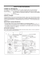

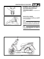
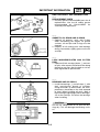
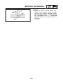
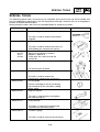


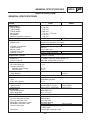
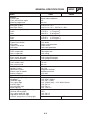
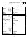


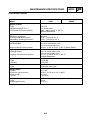

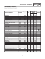
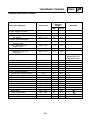

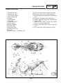
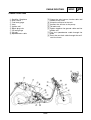
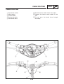


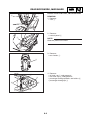
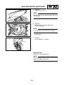
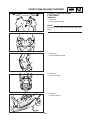
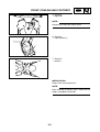
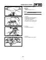
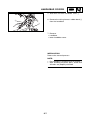
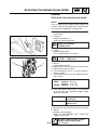
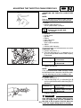
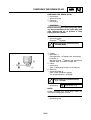
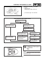
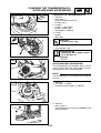

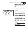


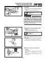


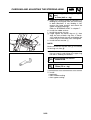
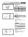

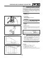
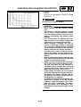

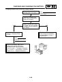
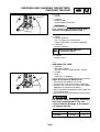


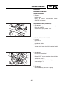
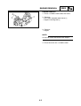
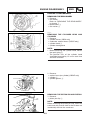
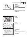
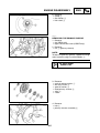

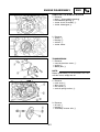

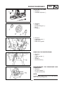
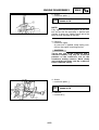


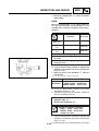
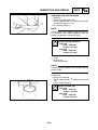
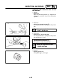

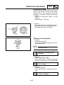
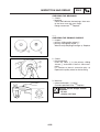
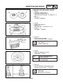

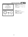
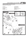
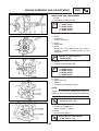
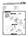

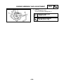

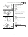
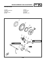
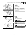
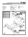

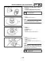

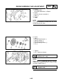
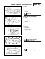


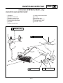
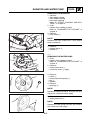
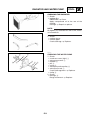
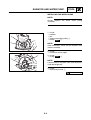


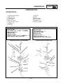

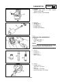
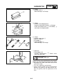
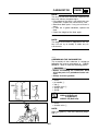
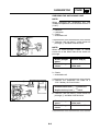
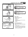
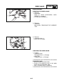
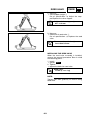

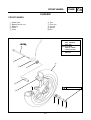
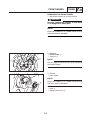


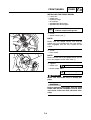

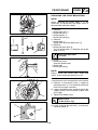

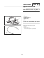
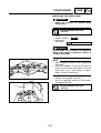
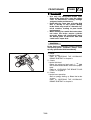
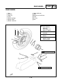

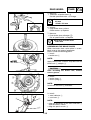
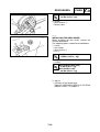
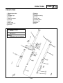

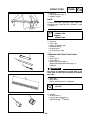
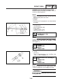
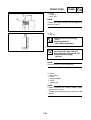

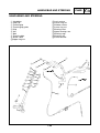

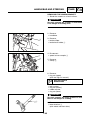
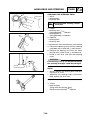
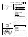
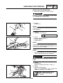


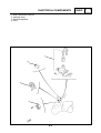
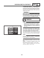
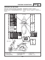
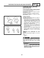


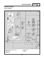
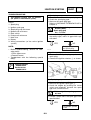
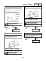
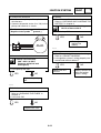

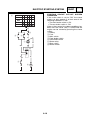
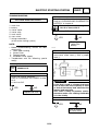
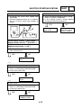
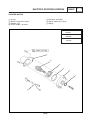


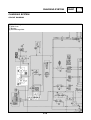
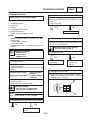


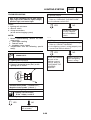

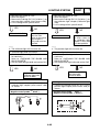


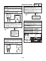


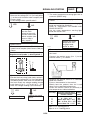


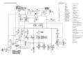
![Manuale Officina [ ITA ] Yamaha R1 2002-2003](http://vs1.manualzilla.com/store/data/006110674_1-52d32bbc9127defc0419b49b1226ec2b-150x150.png)