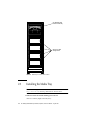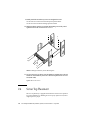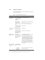
1
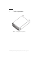
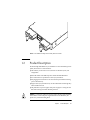
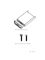
Sun StorEdge™ D240 Media Tray
Installation, Operation,
and Service Manual
Sun Microsystems, Inc.
901 San Antonio Road
Palo Alto, CA 94303
U.S.A. 650-960-1300
Part No. 806-4211-12
August 2001, Revision A
Send comments about this document to: [email protected]
Copyright 2001 Sun Microsystems, Inc., 901 San Antonio Road, Palo Alto, CA 94303-4900 U.S.A. All rights reserved.
This product or document is distributed under licenses restricting its use, copying, distribution, and decompilation. No part of this product or
document may be reproduced in any form by any means without prior written authorization of Sun and its licensors, if any. Third-party
software, including font technology, is copyrighted and licensed from Sun suppliers.
Parts of the product may be derived from Berkeley BSD systems, licensed from the University of California. UNIX is a registered trademark in
the U.S. and other countries, exclusively licensed through X/Open Company, Ltd.
Sun, Sun Microsystems, the Sun logo, AnswerBook2, docs.sun.com, Sun StorEdge and Solaris are trademarks, registered trademarks, or service
marks of Sun Microsystems, Inc. in the U.S. and other countries. All SPARC trademarks are used under license and are trademarks or registered
trademarks of SPARC International, Inc. in the U.S. and other countries. Products bearing SPARC trademarks are based upon an architecture
developed by Sun Microsystems, Inc. The Energy Star logo is a registered trademark of EPA.
The OPEN LOOK and Sun™ Graphical User Interface was developed by Sun Microsystems, Inc. for its users and licensees. Sun acknowledges
the pioneering efforts of Xerox in researching and developing the concept of visual or graphical user interfaces for the computer industry. Sun
holds a non-exclusive license from Xerox to the Xerox Graphical User Interface, which license also covers Sun’s licensees who implement OPEN
LOOK GUIs and otherwise comply with Sun’s written license agreements.
Federal Acquisitions: Commercial Software—Government Users Subject to Standard License Terms and Conditions.
DOCUMENTATION IS PROVIDED “AS IS” AND ALL EXPRESS OR IMPLIED CONDITIONS, REPRESENTATIONS AND WARRANTIES,
INCLUDING ANY IMPLIED WARRANTY OF MERCHANTABILITY, FITNESS FOR A PARTICULAR PURPOSE OR NON-INFRINGEMENT,
ARE DISCLAIMED, EXCEPT TO THE EXTENT THAT SUCH DISCLAIMERS ARE HELD TO BE LEGALLY INVALID.
Copyright 2001 Sun Microsystems, Inc., 901 San Antonio Road, Palo Alto, CA 94303-4900 Etats-Unis. Tous droits réservés.
Ce produit ou document est distribué avec des licences qui en restreignent l’utilisation, la copie, la distribution, et la décompilation. Aucune
partie de ce produit ou document ne peut être reproduite sous aucune forme, par quelque moyen que ce soit, sans l’autorisation préalable et
écrite de Sun et de ses bailleurs de licence, s’il y en a. Le logiciel détenu par des tiers, et qui comprend la technologie relative aux polices de
caractères, est protégé par un copyright et licencié par des fournisseurs de Sun.
Des parties de ce produit pourront être dérivées des systèmes Berkeley BSD licenciés par l’Université de Californie. UNIX est une marque
déposée aux Etats-Unis et dans d’autres pays et licenciée exclusivement par X/Open Company, Ltd.
Sun, Sun Microsystems, le logo Sun, AnswerBook2, docs.sun.com, Sun StorEdge et Solaris sont des marques de fabrique ou des marques
déposées, ou marques de service, de Sun Microsystems, Inc. aux Etats-Unis et dans d’autres pays. Toutes les marques SPARC sont utilisées sous
licence et sont des marques de fabrique ou des marques déposées de SPARC International, Inc. aux Etats-Unis et dans d’autres pays. Les
produits portant les marques SPARC sont basés sur une architecture développée par Sun Microsystems, Inc.
L’interface d’utilisation graphique OPEN LOOK et Sun™ a été développée par Sun Microsystems, Inc. pour ses utilisateurs et licenciés. Sun
reconnaît les efforts de pionniers de Xerox pour la recherche et le développement du concept des interfaces d’utilisation visuelle ou graphique
pour l’industrie de l’informatique. Sun détient une licence non exclusive de Xerox sur l’interface d’utilisation graphique Xerox, cette licence
couvrant également les licenciés de Sun qui mettent en place l’interface d’utilisation graphique OPEN LOOK et qui en outre se conforment aux
licences écrites de Sun.
LA DOCUMENTATION EST FOURNIE “EN L’ETAT” ET TOUTES AUTRES CONDITIONS, DECLARATIONS ET GARANTIES EXPRESSES
OU TACITES SONT FORMELLEMENT EXCLUES, DANS LA MESURE AUTORISEE PAR LA LOI APPLICABLE, Y COMPRIS NOTAMMENT
TOUTE GARANTIE IMPLICITE RELATIVE A LA QUALITE MARCHANDE, A L’APTITUDE A UNE UTILISATION PARTICULIERE OU A
L’ABSENCE DE CONTREFAÇON.
Please
Recycle
Regulatory Compliance Statements
Your Sun product is marked to indicate its compliance class:
•
•
•
•
Federal Communications Commission (FCC) — USA
Industry Canada Equipment Standard for Digital Equipment (ICES-003) — Canada
Voluntary Control Council for Interference (VCCI) — Japan
Bureau of Standards Metrology and Inspection (BSMI) — Taiwan
Please read the appropriate section that corresponds to the marking on your Sun product before attempting to install the
product.
FCC Class A Notice
This device complies with Part 15 of the FCC Rules. Operation is subject to the following two conditions:
1. This device may not cause harmful interference.
2. This device must accept any interference received, including interference that may cause undesired operation.
Note: This equipment has been tested and found to comply with the limits for a Class A digital device, pursuant to Part 15 of
the FCC Rules. These limits are designed to provide reasonable protection against harmful interference when the equipment
is operated in a commercial environment. This equipment generates, uses, and can radiate radio frequency energy, and if it is
not installed and used in accordance with the instruction manual, it may cause harmful interference to radio communications.
Operation of this equipment in a residential area is likely to cause harmful interference, in which case the user will be required
to correct the interference at his own expense.
Shielded Cables: Connections between the workstation and peripherals must be made using shielded cables to comply with
FCC radio frequency emission limits. Networking connections can be made using unshielded twisted-pair (UTP) cables.
Modifications: Any modifications made to this device that are not approved by Sun Microsystems, Inc. may void the authority
granted to the user by the FCC to operate this equipment.
FCC Class B Notice
This device complies with Part 15 of the FCC Rules. Operation is subject to the following two conditions:
1. This device may not cause harmful interference.
2. This device must accept any interference received, including interference that may cause undesired operation.
Note: This equipment has been tested and found to comply with the limits for a Class B digital device, pursuant to Part 15 of
the FCC Rules. These limits are designed to provide reasonable protection against harmful interference in a residential
installation. This equipment generates, uses and can radiate radio frequency energy and, if not installed and used in
accordance with the instructions, may cause harmful interference to radio communications. However, there is no guarantee
that interference will not occur in a particular installation. If this equipment does cause harmful interference to radio or
television reception, which can be determined by turning the equipment off and on, the user is encouraged to try to correct the
interference by one or more of the following measures:
•
•
•
•
Reorient or relocate the receiving antenna.
Increase the separation between the equipment and receiver.
Connect the equipment into an outlet on a circuit different from that to which the receiver is connected.
Consult the dealer or an experienced radio/television technician for help.
Shielded Cables: Connections between the workstation and peripherals must be made using shielded cables in order to
maintain compliance with FCC radio frequency emission limits. Networking connections can be made using unshielded
twisted pair (UTP) cables.
Modifications: Any modifications made to this device that are not approved by Sun Microsystems, Inc. may void the authority
granted to the user by the FCC to operate this equipment.
iii
ICES-003 Class A Notice - Avis NMB-003, Classe A
This Class A digital apparatus complies with Canadian ICES-003.
Cet appareil numérique de la classe A est conforme à la norme NMB-003 du Canada.
ICES-003 Class B Notice - Avis NMB-003, Classe B
This Class B digital apparatus complies with Canadian ICES-003.
Cet appareil numérique de la classe B est conforme à la norme NMB-003 du Canada.
iv
Sun StorEdge D240 Media Tray Installation, Operation, and Service Manual • August 2001
BSMI Class A Notice
The following statement is applicable to products shipped to Taiwan and marked as Class A on the product compliance
label.
v
vi
Sun StorEdge D240 Media Tray Installation, Operation, and Service Manual • August 2001
Safety Agency Compliance
Statements
Depending on the type of power switch your device has,
one of the following symbols may be used:
Caution – Removes AC power from the
system.
Read this section before beginning any procedure. The
following text provides safety precautions to follow when
installing a Sun Microsystems product.
Safety Precautions
For your protection, observe the following safety
precautions when setting up your equipment:
■
■
■
Follow all cautions and instructions marked on the
equipment.
Ensure that the voltage and frequency of your power
source match the voltage and frequency inscribed on
the equipment’s electrical rating label.
Never push objects of any kind through openings in
the equipment. Dangerous voltages may be present.
Conductive foreign objects could produce a short
circuit that could cause fire, electric shock, or damage
to your equipment.
Symbols
The following symbols may appear in this book:
Caution – There is a risk of personal injury
and equipment damage. Follow the
instructions.
Caution – The On/Standby switch is in the
standby position.
Modifications to Equipment
Do not make mechanical or electrical modifications to the
equipment. Sun Microsystems is not responsible for
regulatory compliance of a modified Sun product.
Placement of a Sun Product
Caution – Do not block or cover the openings
of your Sun product. Never place a Sun
product near a radiator or heat register.
Failure to follow these guidelines can cause
overheating and affect the reliability of your
Sun product.
Caution – The workplace-dependent noise
level defined in DIN 45 635 Part 1000 must be
70Db(A) or less.
Caution – Hot surface. Avoid contact.
Surfaces are hot and may cause personal
injury if touched.
Caution – Hazardous voltages are present. To
reduce the risk of electric shock and danger to
personal health, follow the instructions.
Caution – Applies AC power to the system.
vii
SELV Compliance
Safety status of I/O connections comply to SELV
requirements.
Power Cord Connection
Caution – Sun products are designed to work
with single-phase power systems having a
grounded neutral conductor. To reduce the
risk of electric shock, do not plug Sun
products into any other type of power system.
Contact your facilities manager or a qualified
electrician if you are not sure what type of
power is supplied to your building.
Caution – Not all power cords have the same
current ratings. Household extension cords do
not have overload protection and are not
meant for use with computer systems. Do not
use household extension cords with your Sun
product.
Caution – Your Sun product is shipped with a
grounding type (three-wire) power cord. To
reduce the risk of electric shock, always plug
the cord into a grounded power outlet
The following caution applies only to devices with a
Standby power switch:
Caution – The power switch of this product
functions as a standby type device only. The
power cord serves as the primary disconnect
device for the system. Be sure to plug the
power cord into a grounded power outlet that
is nearby the system and is readily accessible.
Do not connect the power cord when the
power supply has been removed from the
system chassis.
viii
Lithium Battery
Caution – On Sun CPU boards, there is a
lithium battery molded into the real-time
clock, SGS No. MK48T59Y, MK48TXXB-XX,
MK48T18-XXXPCZ, M48T59W-XXXPCZ, or
MK48T08. Batteries are not customer
replaceable parts. They may explode if
mishandled. Do not dispose of the battery in
fire. Do not disassemble it or attempt to
recharge it.
Battery Pack
Caution – There is a sealed lead acid battery
in Product Name units. Portable Energy
Products No. TLC02V50. There is danger of
explosion if the battery pack is mishandled or
incorrectly replaced. Replace only with the
same type of Sun Microsystems battery pack.
Do not disassemble it or attempt to recharge it
outside the system. Do not dispose of the
battery in fire. Dispose of the battery properly
in accordance with local regulations
System Unit Cover
You must remove the cover of your Sun computer system
unit to add cards, memory, or internal storage devices. Be
sure to replace the top cover before powering on your
computer system.
Caution – Do not operate Sun products
without the top cover in place. Failure to take
this precaution may result in personal injury
and system damage.
Laser Compliance Notice
Symbole
Sun products that use laser technology comply with Class 1
laser requirements.
Die Symbole in diesem Handbuch haben folgende
Bedeutung:
Achtung – Gefahr von Verletzung und
Geräteschaden. Befolgen Sie die Anweisungen
Class 1 Laser Product
Luokan 1 Laserlaite
Klasse 1 Laser Apparat
Laser KLasse 1
CD-ROM
Caution – Use of controls, adjustments, or the
performance of procedures other than those
specified herein may result in hazardous
radiation exposure.
Einhaltung sicherheitsbehördlicher
Vorschriften
Auf dieser Seite werden Sicherheitsrichtlinien beschrieben,
die bei der Installation von Sun-Produkten zu beachten
sind.
Achtung – Hohe Temperatur. Nicht berühren,
da Verletzungsgefahr durch heiße Oberfläche
besteht.
Achtung – Gefährliche Spannungen.
Anweisungen befolgen, um Stromschläge und
Verletzungen zu vermeiden
Achtung – Setzt das System unter
Wechselstrom
Je nach Netzschaltertyp an Ihrem Gerät kann eines der
folgenden Symbole benutzt werden:
Achtung – Unterbricht die
Wechselstromzufuhr zum Gerät.
Sicherheitsvorkehrungen
Treffen Sie zu Ihrem eigenen Schutz die folgenden
Sicherheitsvorkehrungen, wenn Sie Ihr Gerät installieren:
■
■
■
Beachten Sie alle auf den Geräten angebrachten
Warnhinweise und Anweisungen.
Vergewissern Sie sich, daß Spannung und Frequenz
Ihrer Stromquelle mit der Spannung und Frequenz
übereinstimmen, die auf dem Etikett mit den
elektrischen Nennwerten des Geräts angegeben sind.
Stecken Sie auf keinen Fall irgendwelche Gegenstände
in Öffnungen in den Geräten. Leitfähige Gegenstände
könnten aufgrund der möglicherweise vorliegenden
gefährlichen Spannungen einen Kurzschluß
verursachen, der einen Brand, Stromschlag oder
Geräteschaden herbeiführen kann.
Achtung – (Stand-by-Position) - Der Ein-/
Wartezustand-Schalter steht auf
Wartezustand. Änderungen an Sun-Geräten.
Nehmen Sie keine mechanischen oder elektrischen
Änderungen an den Geräten vor. Sun Microsystems,
übernimmt bei einem Sun-Produkt, das geändert wurde,
keine Verantwortung für die Einhaltung behördlicher
Vorschriften
ix
Aufstellung von Sun-Geräten
Achtung – Um den zuverlässigen Betrieb
Ihres Sun-Geräts zu gewährleisten und es vor
Überhitzung zu schützen, dürfen die
Öffnungen im Gerät nicht blockiert oder
verdeckt werden. Sun-Produkte sollten
niemals in der Nähe von Heizkörpern oder
Heizluftklappen aufgestellt werden
Achtung – Der arbeitsplatzbezogene
Schalldruckpegel nach DIN 45 635 Teil 1000
beträgt 70Db(A) oder weniger.
Die folgende Warnung gilt nur für Geräte mit
Wartezustand-Netzschalter:
Achtung – Der Ein/Aus-Schalter dieses
Geräts schaltet nur auf Wartezustand (StandBy-Modus). Um die Stromzufuhr zum Gerät
vollständig zu unterbrechen, müssen Sie das
Netzkabel von der Steckdose abziehen.
Schließen Sie den Stecker des Netzkabels an
eine in der Nähe befindliche, frei zugängliche,
geerdete Netzsteckdose an. Schließen Sie das
Netzkabel nicht an, wenn das Netzteil aus der
Systemeinheit entfernt wurde.
Lithiumbatterie
Einhaltung der SELV-Richtlinien
Die Sicherung der I/O-Verbindungen entspricht den
Anforderungen der SELV-Spezifikation.
Anschluß des Netzkabels
Achtung – Sun-Produkte sind für den Betrieb
an Einphasen-Stromnetzen mit geerdetem
Nulleiter vorgesehen. Um die
Stromschlaggefahr zu reduzieren, schließen
Sie Sun-Produkte nicht an andere
Stromquellen an. Ihr Betriebsleiter oder ein
qualifizierter Elektriker kann Ihnen die Daten
zur Stromversorgung in Ihrem Gebäude
geben.
Achtung – Nicht alle Netzkabel haben die
gleichen Nennwerte. Herkömmliche, im
Haushalt verwendete Verlängerungskabel
besitzen keinen Überlastungsschutz und sind
daher für Computersysteme nicht geeignet.
Achtung – Ihr Sun-Gerät wird mit einem
dreiadrigen Netzkabel für geerdete
Netzsteckdosen geliefert. Um die Gefahr eines
Stromschlags zu reduzieren, schließen Sie das
Kabel nur an eine fachgerecht verlegte,
geerdete Steckdose an.
x
Achtung – CPU-Karten von Sun verfügen
über eine Echtzeituhr mit integrierter
Lithiumbatterie (Teile-Nr. MK48T59Y,
MK48TXXB-XX, MK48T18-XXXPCZ,
M48T59W-XXXPCZ, oder MK48T08). Diese
Batterie darf nur von einem qualifizierten
Servicetechniker ausgewechselt werden, da sie
bei falscher Handhabung explodieren kann.
Werfen Sie die Batterie nicht ins Feuer.
Versuchen Sie auf keinen Fall, die Batterie
auszubauen oder wiederaufzuladen.
Batterien
Achtung – Die Geräte Product Name
enthalten auslaufsichere Bleiakkumulatoren.
Produkt-Nr. TLC02V50 für portable
Stromversorgung. Werden bei der Behandlung
oder beim Austausch der Batterie Fehler
gemacht, besteht Explosionsgefahr. Batterie
nur gegen Batterien gleichen Typs von Sun
Microsystems austauschen. Nicht demontieren
und nicht versuchen, die Batterie außerhalb
des Geräts zu laden. Batterie nicht ins Feuer
werfen. Ordnungsgemäß entsprechend den
vor Ort geltenden Vorschriften entsorgen.
Gehäuseabdeckung
Sie müssen die obere Abdeckung Ihres Sun-Systems
entfernen, um interne Komponenten wie Karten,
Speicherchips oder Massenspeicher hinzuzufügen. Bringen
Sie die obere Gehäuseabdeckung wieder an, bevor Sie Ihr
System einschalten.
Achtung – Bei Betrieb des Systems ohne obere
Abdeckung besteht die Gefahr von
Stromschlag und Systemschäden.
Einhaltung der Richtlinien für Laser
Sun-Produkte, die mit Laser-Technologie arbeiten,
entsprechen den Anforderungen der Laser Klasse 1.
Class 1 Laser Product
Luokan 1 Laserlaite
Klasse 1 Laser Apparat
Laser KLasse 1
CD-ROM
Achtung – Die Verwendung von anderen
Steuerungen und Einstellungen oder die
Durchfhrung von Prozeduren, die von den
hier beschriebenen abweichen, knnen
gefhrliche Strahlungen zur Folge haben.
Conformité aux normes de sécurité
Ce texte traite des mesures de sécurité qu’il convient de
prendre pour l’installation d’un produit Sun Microsystems.
Mesures de sécurité
Pour votre protection, veuillez prendre les précautions
suivantes pendant l’installation du matériel :
■
■
■
Ne jamais introduire d’objets quels qu’ils soient dans
une des ouvertures de l’appareil. Vous pourriez vous
trouver en présence de hautes tensions dangereuses.
Tout objet conducteur introduit de la sorte pourrait
produire un court-circuit qui entraînerait des
flammes, des risques d’électrocution ou des dégâts
matériels.
Symboles
Vous trouverez ci-dessous la signification des différents
symboles utilisés :
Attention – risques de blessures corporelles et
de dégâts matériels. Veuillez suivre les
instructions.
Attention – surface à température élevée.
Evitez le contact. La température des surfaces
est élevée et leur contact peut provoquer des
blessures corporelles.
Attention – présence de tensions dangereuses.
Pour éviter les risques d’électrocution et de
danger pour la santé physique, veuillez suivre
les instructions.
Attention – Votre système est sous tension
(courant alternatif).
Un des symboles suivants sera peut-être utilisé en fonction
du type d'interrupteur de votre système:
Attention – Votre système est hors tension
(courant alternatif).
Attention – L'interrupteur Marche/Veilleuse
est en position « Veilleuse ».
Suivre tous les avertissements et toutes les
instructions inscrites sur le matériel.
Vérifier que la tension et la fréquence de la source
d’alimentation électrique correspondent à la tension et
à la fréquence indiquées sur l’étiquette de
classification de l’appareil.
xi
Modification du matériel
Ne pas apporter de modification mécanique ou électrique
au matériel. Sun Microsystems n’est pas responsable de la
conformité réglementaire d’un produit Sun qui a été
modifié.
Positionnement d’un produit Sun
Attention – pour assurer le bon
fonctionnement de votre produit Sun et pour
l’empêcher de surchauffer, il convient de ne
pas obstruer ni recouvrir les ouvertures
prévues dans l’appareil. Un produit Sun ne
doit jamais être placé à proximité d’un
radiateur ou d’une source de chaleur.
Attention – Le niveau de pression acoustique
au poste de travail s'élève selon la norme DIN
45 635 section 1000, à 70 dB (A) ou moins.
Conformité SELV
Sécurité : les raccordements E/S sont conformes aux
normes SELV.
Connexion du cordon d’alimentation
Attention – les produits Sun sont conçus pour
fonctionner avec des alimentations
monophasées munies d’un conducteur neutre
mis à la terre. Pour écarter les risques
d’électrocution, ne pas brancher de produit
Sun dans un autre type d’alimentation secteur.
En cas de doute quant au type d’alimentation
électrique du local, veuillez vous adresser au
directeur de l’exploitation ou à un électricien
qualifié.
xii
Attention – tous les cordons d’alimentation
n’ont pas forcément la même puissance
nominale en matière de courant. Les rallonges
d’usage domestique n’offrent pas de
protection contre les surcharges et ne sont pas
prévues pour les systèmes d’ordinateurs. Ne
pas utiliser de rallonge d’usage domestique
avec votre produit Sun.
Attention – votre produit Sun a été livré
équipé d’un cordon d’alimentation à trois fils
(avec prise de terre). Pour écarter tout risque
d’électrocution, branchez toujours ce cordon
dans une prise mise à la terre.
L'avertissement suivant s'applique uniquement aux
systèmes équipés d'un interrupteur VEILLEUSE:
Attention – Le commutateur d’alimentation
de ce produit fonctionne comme un dispositif
de mise en veille uniquement. C’est la prise
d’alimentation qui sert à mettre le produit
hors tension. Veillez donc à installer le produit
à proximité d’une prise murale facilement
accessible. Ne connectez pas la prise
d’alimentation lorsque le châssis du système
n’est plus alimenté.
Batterie au lithium
Attention – sur les cartes CPU Sun, une
batterie au lithium (référence MK48T59Y,
MK48TXXB-XX, MK48T18-XXXPCZ,
M48T59W-XXXPCZ, ou MK48T08.) a été
moulée dans l’horloge temps réel SGS. Les
batteries ne sont pas des pièces remplaçables
par le client. Elles risquent d’exploser en cas
de mauvais traitement. Ne pas jeter la batterie
au feu. Ne pas la démonter ni tenter de la
recharger.
Bloc-batterie
CD-ROM
Attention – Les unités Product Name
contiennent une batterie étanche au plomb
(produits énergétiques portatifs n˚TLC02V50).
Il existe un risque d’explosion si ce blocbatterie est manipulé de façon erronée ou mal
mis en place. Ne remplacez ce bloc que par un
bloc-batterie Sun Microsystems du même
type. Ne le démontez pas et n’essayez pas de
le recharger hors du système. Ne faites pas
brûler la batterie mais mettez-la au rebut
conformément aux réglementations locales en
vigueur.
Attention – L’utilisation de contrôles, de
réglages ou de performances de procédures
autre que celle spécifiée dans le présent
document peut provoquer une exposition à
des radiations dangereuses.
Normativas de seguridad
El siguiente texto incluye las medidas de seguridad que se
deben seguir cuando se instale algún producto de Sun
Microsystems.
Precauciones de seguridad
Couvercle
Pour ajouter des cartes, de la mémoire, ou des unités de
stockage internes, vous devrez démonter le couvercle de
l’unité système Sun. Ne pas oublier de remettre ce couvercle
en place avant de mettre le système sous tension.
Attention – il est dangereux de faire
fonctionner un produit Sun sans le couvercle
en place. Si l’on néglige cette précaution, on
encourt des risques de blessures corporelles et
de dégâts matériels.
Conformité aux certifications Laser
Les produits Sun qui font appel aux technologies lasers sont
conformes aux normes de la classe 1 en la matière.
Class 1 Laser Product
Luokan 1 Laserlaite
Klasse 1 Laser Apparat
Laser KLasse 1
Para su protección observe las siguientes medidas de
seguridad cuando manipule su equipo:
■
■
■
Siga todas los avisos e instrucciones marcados en el
equipo.
Asegúrese de que el voltaje y la frecuencia de la red
eléctrica concuerdan con las descritas en las etiquetas
de especificaciones eléctricas del equipo.
No introduzca nunca objetos de ningún tipo a través
de los orificios del equipo. Pueden haber voltajes
peligrosos. Los objetos extraños conductores de la
electricidad pueden producir cortocircuitos que
provoquen un incendio, descargas eléctricas o daños
en el equipo.
Símbolos
En este libro aparecen los siguientes símbolos:
Precaución – Existe el riesgo de lesiones
personales y daños al equipo. Siga las
instrucciones.
Precaución – Superficie caliente. Evite el
contacto. Las superficies están calientes y
pueden causar daños personales si se tocan.
Precaución – Voltaje peligroso presente. Para
reducir el riesgo de descarga y daños para la
salud siga las instrucciones.
xiii
Precaución – Aplica la alimentación de CA al
sistema.
Según el tipo de interruptor de encendido que su equipo
tenga, es posible que se utilice uno de los siguientes
símbolos:
Precaución – Elimina la alimentación de CA
del sistema.
Precaución – El interruptor de Encendido/En
espera se ha colocado en la posición de En
espera.
Modificaciones en el equipo
No realice modificaciones de tipo mecánico o eléctrico en el
equipo. Sun Microsystems no se hace responsable del
cumplimiento de las normativas de seguridad en los
equipos Sun modificados.
Ubicación de un producto Sun
Precaución – Para asegurar la fiabilidad de
funcionamiento de su producto Sun y para
protegerlo de sobrecalentamien-tos no deben
obstruirse o taparse las rejillas del equipo. Los
productos Sun nunca deben situarse cerca de
radiadores o de fuentes de calor.
Precaución – De acuerdo con la norma DIN
45 635, Parte 1000, se admite un nivel de
presión acústica para puestos de trabajo
máximo de 70Db(A).
Cumplimiento de la normativa SELV
El estado de la seguridad de las conexiones de entrada/
salida cumple los requisitos de la normativa SELV.
xiv
Conexión del cable de alimentación eléctrica
Precaución – Los productos Sun están
diseñados para trabajar en una red eléctrica
monofásica con toma de tierra. Para reducir el
riesgo de descarga eléctrica, no conecte los
productos Sun a otro tipo de sistema de
alimentación eléctrica. Póngase en contacto
con el responsable de mantenimiento o con un
electricista cualificado si no está seguro del
sistema de alimentación eléctrica del que se
dispone en su edificio.
Precaución – No todos los cables de
alimentación eléctrica tienen la misma
capacidad. Los cables de tipo doméstico no
están provistos de protecciones contra
sobrecargas y por tanto no son apropiados
para su uso con computadores. No utilice
alargadores de tipo doméstico para conectar
sus productos Sun.
Precaución – Con el producto Sun se
proporciona un cable de alimentación con
toma de tierra. Para reducir el riesgo de
descargas eléctricas conéctelo siempre a un
enchufe con toma de tierra.
La siguiente advertencia se aplica solamente a equipos con
un interruptor de encendido que tenga una posición "En
espera":
Precaución – El interruptor de encendido de
este producto funciona exclusivamente como
un dispositivo de puesta en espera. El enchufe
de la fuente de alimentación está diseñado
para ser el elemento primario de desconexión
del equipo. El equipo debe instalarse cerca del
enchufe de forma que este último pueda ser
fácil y rápidamente accesible. No conecte el
cable de alimentación cuando se ha retirado la
fuente de alimentación del chasis del sistema.
Batería de litio
Precaución – En las placas de CPU Sun hay
una batería de litio insertada en el reloj de
tiempo real, tipo SGS Núm. MK48T59Y,
MK48TXXB-XX, MK48T18-XXXPCZ,
M48T59W-XXXPCZ, o MK48T08. Las baterías
no son elementos reemplazables por el propio
cliente. Pueden explotar si se manipulan de
forma errónea. No arroje las baterías al fuego.
No las abra o intente recargarlas.
Paquete de pilas
Precaución – Las unidades Product Name
contienen una pila de plomo sellada,
Productos de energía portátil nº TLC02V50.
Existe riesgo de estallido si el paquete de pilas
se maneja sin cuidado o se sustituye de
manera indebida. Las pilas sólo deben
sustituirse por el mismo tipo de paquete de
pilas de Sun Microsystems. No las desmonte
ni intente recargarlas fuera del sistema. No
arroje las pilas al fuego. Deséchelas siguiendo
el método indicado por las disposiciones
vigentes.
Aviso de cumplimiento con requisitos de láser
Los productos Sun que utilizan la tecnología de láser
cumplen con los requisitos de láser de Clase 1.
Class 1 Laser Product
Luokan 1 Laserlaite
Klasse 1 Laser Apparat
Laser KLasse 1
CD-ROM
Precaución – El manejo de los controles, los
ajustes o la ejecución de procedimientos
distintos a los aquí especificados pueden
exponer al usuario a radiaciones peligrosas.
GOST-R Certification Mark
Tapa de la unidad del sistema
Debe quitar la tapa del sistema cuando sea necesario añadir
tarjetas, memoria o dispositivos de almacenamiento
internos. Asegúrese de cerrar la tapa superior antes de
volver a encender el equipo.
Precaución – Es peligroso hacer funcionar los
productos Sun sin la tapa superior colocada.
El hecho de no tener en cuenta esta precaución
puede ocasionar daños personales o
perjudicar el funcionamiento del equipo.
xv
Nordic Lithium Battery Cautions
Norge
Caution – Litiumbatteri —
Eksplosjonsfare.Ved utskifting benyttes kun
batteri som anbefalt av apparatfabrikanten.
Brukt batteri returneres apparatleverandøren.
Sverige
Caution – Explosionsfara vid felaktigt
batteribyte. Använd samma batterityp eller en
ekvivalent typ som rekommenderas av
apparattillverkaren. Kassera använt batteri
enligt fabrikantens instruktion.
Danmark
Caution – Litiumbatteri — Eksplosionsfare
ved fejlagtig håndtering. Udskiftning må kun
ske med batteri af samme fabrikat og type.
Levér det brugte batteri tilbage til
leverandøren.
Suomi
Caution – Paristo voi räjähtää, jos se on
virheellisesti asennettu. Vaihda paristo
ainoastaan laitevalmistajan suosittelemaan
tyyppiin. Hävitä käytetty paristo valmistajan
ohjeiden mukaisesti.
xvi
Contents
Regulatory Compliance Statements
Preface
1.
xix
Product Description
1-1
Product Appearance
1-2
Product Description
1-5
Standard Hardware Configurations
Mounting
Installation
1-7
2-1
Tools and Parts Needed
Placement in the Rack
2-1
2-5
Installing the Media Tray
Server Top Placement
3.
Operation
1-6
1-6
Software Requirements
2.
iii
2-6
2-10
3-1
Drive Configuration
Bus Configuration
3-2
3-3
Configuration Switch
3-3
xvii
Bus Configuration Cabling
3-4
Recommended External SCSI Cables
3-4
Full Bus Cabling and Switch Setting
3-4
Split Bus Cabling and Switch Setting
SCSI Host Connection Requirement
3-5
3-6
Powering On or Off and Booting the Host System
Booting from the DVD-ROM Drive
Subsequent Booting
Reading Status LEDs
Troubleshooting
3-8
3-11
Hardware Problems
Service
3-7
3-8
Software Precautions
4.
3-6
3-11
3-12
4-1
Field Replaceable Units
Hard Drives
4-1
4-1
Hot-Plugging Hard Drives
Adding Hard Drives
4-1
4-3
Replacing a Hard Drive
4-6
Replacing a Drive With a UNIX File System
4-7
Replacing a Drive Using the Solstice DiskSuite Software
DVD-ROM Drive, Tape Drive, or Hard Drive on a Sled Assembly
Removing a Sled Assembly
4-15
Replacing a Sled Assembly
4-16
Power Supply
xviii
4-16
Removing a Power Supply
4-16
Replacing a Power Supply
4-17
Sun StorEdge D240 Media Tray Installation, Operation, and Service Manual • August 2001
4-10
4-15
Preface
The Sun StorEdge D240 Media Tray Installation, Operation, and Service Manual provides
information and procedures about installing, operating, and servicing the Sun
StorEdge™ media tray.
These procedures are designed for an experienced system administrator.
Using UNIX Commands
This document may not contain information on basic UNIX® commands and
procedures such as shutting down the system, booting the system, and configuring
devices.
See one or more of the following for this information:
■
Solaris Handbook for Sun Peripherals
■
AnswerBook2™ online documentation for the Solaris™ operating environment
■
Other software documentation that you received with your system
xix
Typographic Conventions
Typeface
Meaning
Examples
AaBbCc123
The names of commands, files,
and directories; on-screen
computer output
Edit your .login file.
Use ls -a to list all files.
% You have mail.
AaBbCc123
What you type, when
contrasted with on-screen
computer output
% su
Password:
AaBbCc123
Book titles, new words or
terms, words to be emphasized
Read Chapter 6 in the User’s Guide.
These are called class options.
You must be superuser to do this.
Command-line variable;
replace with a real name or
value
To delete a file, type rm filename.
Shell Prompts
xx
Shell
Prompt
C shell
machine_name%
C shell superuser
machine_name#
Bourne shell and Korn shell
$
Bourne shell and Korn shell superuser
#
Sun StorEdge D240 Media Tray Installation, Operation, and Service Manual • August 2001
Related Documentation
Application
Title
Part Number
Installation
Sun StorEdge Expansion Cabinet Airflow
Baffle Installation Guide
806-0274
Sun StorEdge Expansion Cabinet
Installation Guide for the Sun Enterprise™
4x00
805-7687
Sun StorEdge DVD 10X Installation and
User’s Guide
806-5518
Sun StorEdge DDS-4 Tape Drive
Installation and User’s Guide
806-3313
Installation and service
Sun StorEdge Expansion Cabinet
Installation and Service Manual
805-3067
Diagnostic testing
SunVTS™ 4.0 Test Reference Manual
806-2058
SunVTS 4.0 User’s Guide
806-2057
Installation and operation
Rackmount placement
http://docs.sun.com
Click Storage, then Rackmount Placement
Matrix
Accessing Sun Documentation Online
The Products and Solution web site enables you to access Sun™ technical
documentation on the Web. You can browse the Products and Solutions
archive or search for a specific book title or subject at:
http://www.sun.com/products-n-solutions/
Preface
xxi
Ordering Sun Documentation
Fatbrain.com, an Internet professional bookstore, stocks select product
documentation from Sun Microsystems, Inc.
For a list of documents and how to order them, visit the Sun Documentation Center
on Fatbrain.com at:
http://www.fatbrain.com/documentation/sun
Sun Welcomes Your Comments
Sun is interested in improving its documentation and welcomes your comments and
suggestions. You can email your comments to Sun at:
[email protected]
Please include the part number of your document in the subject line of your email.
xxii
Sun StorEdge D240 Media Tray Installation, Operation, and Service Manual • August 2001
CHAPTER
1
Product Description
This chapter consists of the following sections:
■
■
■
■
■
Section 1.1
Section 1.2
Section 1.3
Section 1.4
Section 1.5
“Product Appearance” on page 1-2
“Product Description” on page 1-5
“Standard Hardware Configurations” on page 1-6
“Mounting” on page 1-6
“Software Requirements” on page 1-7
1-1
1.1
Product Appearance
FIGURE 1-1
1-2
Sun StorEdge D240 Server Top Media Tray
Sun StorEdge D240 Media Tray Installation, Operation, and Service Manual • August 2001
FIGURE 1-2
DVD-ROM
drive
FIGURE 1-3
Sun StorEdge D240 Rackmount Media Tray With Removable Front Bezel
Hard drives
in brackets
DDS-4 tape drive
Server Top Media Tray, Front View: Typical Configuration
Chapter 1
Product Description
1-3
Configuration
switch
Split bus LED
FIGURE 1-5
1-4
In
In
Out
Out
SCSI connectors
Power supply
(PS1)
FIGURE 1-4
Full bus LED
Power supply
(PSØ)
Media Tray, Rear View
Mounting Rail
Sun StorEdge D240 Media Tray Installation, Operation, and Service Manual • August 2001
FIGURE 1-6
1.2
DVD-ROM and Tape Drives Partially Removed on Sleds
Product Description
The Sun StorEdge D240 Media Tray accommodates two removable media (tape and
optical) drives and two to four hard drives.
■
The media tray can be used as a boot I/O device for 1828.8-mm (72-in.) rack
configurations.
■
Removable media are the DDS-4 tape drive and the 10X DVD-ROM drive.
■
Two fixed locations are provided for 25.4-mm (1-in.) hard drives.
■
Hot-plugging allows hard drives to be removed and replaced without removing
power to the media tray.
■
Single 25.4-mm (1-in.) hard drives may also be installed in the left and right bays
when assembled on sleds.
■
The product has two power supplies. Each power supply has a cooling fan with
built-in heat sensing for thermal shutdown protection.
Caution – A media tray weighs from 11.34 kg (25 lb) to 22.68 kg (50 lb) depending
on the number of drives and power supplies installed. It must be lifted by two
persons or by a mechanical lifting device.
Chapter 1
Product Description
1-5
Caution – To remove all power from a media tray, you must disconnect the power
cords from both of the power supplies.
1.3
Standard Hardware Configurations
TABLE 1-1
Full Bus Configurations
Configuration Type
Hard Drives
Tape Drives
DVD-ROM Drives
Maximum hard drives and
tape drives
2
2
0
Maximum hard drives
only
4
0
0
Mixed hard drives, tape
drive, and DVD-ROM
drive
2
1
1
Maximum hard drives and
DVD drives
2
0
2
Note – You can order standard configurations from Sun. You must assemble other
configurations with drives ordered from Sun.
1.4
Mounting
The Sun StorEdge D240 Media Tray can be mounted in the following methods:
■
■
■
1-6
Sun StorEdge expansion cabinet.
Sun Enterprise 1828.8-mm (72-in.) system cabinet.
On top of specified Sun deskside systems.
Sun StorEdge D240 Media Tray Installation, Operation, and Service Manual • August 2001
1.5
Software Requirements
■
■
The Solaris 8 operating environment is required on the system.
For diagnostic purposes, SunVTS 4.0 is required.
Chapter 1
Product Description
1-7
1-8
Sun StorEdge D240 Media Tray Installation, Operation, and Service Manual • August 2001
CHAPTER
2
Installation
This chapter consists of the following sections:
■
■
■
■
2.1
Section 2.1
Section 2.2
Section 2.3
Section 2.4
“Tools and Parts Needed” on page 2-1
“Placement in the Rack” on page 2-5
“Installing the Media Tray” on page 2-6
“Server Top Placement” on page 2-10
Tools and Parts Needed
You will need the following tools and parts:
■
■
■
■
■
■
■
One No. 2 Phillips screwdriver
One torque-measuring wrench or screwdriver
Two mounting rails
One Sun StorEdge D240 Media Tray
Fourteen panhead screws
Six or twelve flathead screws
Two mounting ears
2-1
FIGURE 2-1
2-2
Mounting Rail
Sun StorEdge D240 Media Tray Installation, Operation, and Service Manual • August 2001
FIGURE 2-2
Sun StorEdge D240 Rackmount Media Tray
\
/
A
FIGURE 2-3
B
Flathead (A) and Panhead (B) Screws (Enlarged Profiles)
Chapter 2
Installation
2-3
FIGURE 2-4
2-4
Mounting Ear
Sun StorEdge D240 Media Tray Installation, Operation, and Service Manual • August 2001
2.2
Placement in the Rack
A maximum of four media trays can be installed in one rack cabinet.
FIGURE 2-5
Media Tray Placement in a Sun Enterprise System Cabinet Rack
Caution – A media tray weighs from 11.34 kg (25 lbs) to 22.68 kg (50 lbs) depending
on the number of drives and power supplies installed. It must be lifted by two
persons or by a mechanical lifting device.
Chapter 2
Installation
2-5
Sun StorEdge D240
rackmount media tray
Other host or data
storage devices
FIGURE 2-6
2.3
Media Tray in Cabinet Shelf Location
Installing the Media Tray
Note – For mounting hole information, refer to:
http://docs.sun.com, click Storage, then Rackmount Placement Matrix.
1. Estimate or measure the available mounting space in the rack.
Allow for a media tray height of 88.9-mm (3.5-in.).
2-6
Sun StorEdge D240 Media Tray Installation, Operation, and Service Manual • August 2001
2. Align the holes on a mounting ear with a corresponding pair of 12.7-mm (0.5-in. or
1/2-in.) rack holes.
The rack holes are not evenly spaced between each other along the rack. Some are
12.7-mm (0.5-in. or 1/2-in.) spaced, and some are 15.875-mm (0.625-in. or 5/8-in.)
spaced. Only 12.7-mm (0.5-in. or 1/2-in.) spaced holes are used for the mounting
ears.
FIGURE 2-7
Aligning the Mounting Ear Holes With the Rack Holes
3. Attach the mounting ears to the media tray front sides.
■
If you are mounting the media tray in the Sun Enterprise system cabinet, align
only the mounting ear rear holes to the media tray front side holes, as shown in
FIGURE 2-8 B.
■
If you are mounting the media tray in the Sun StorEdge expansion cabinet, align
the mounting ear front and rear holes to themedia tray front and rear side holes, as
shown in FIGURE 2-8 A.
Chapter 2
Installation
2-7
A
B
FIGURE 2-8
Attaching the Mounting Ear to the Media Tray
4. Using a torque-measuring wrench or screwdriver, tighten the flathead screws
through the top and bottom aligned holes to secure each mounting ear to the
media tray front sides.
Tighten all screws to 3.3–4.1 N-m (29–36 in-lbs).
5. Attach the mounting rails.
a. Partially install the top panhead screws in the rack holes on both the left and
right sides of the rack. Do not fully tighten the screws.
The key holes on the rails install in holes one position above the top mounting ear
screw. For example, if you attach the top ear screw at hole 100, you must install
the screws for the key holes at hole 101.
Note – If you are installing the mounting rails in the Sun Enterprise system cabinet,
the key hole in the recessed flange attaches towards the rear of the cabinet, as shown
in FIGURE 2-9 A.
2-8
Sun StorEdge D240 Media Tray Installation, Operation, and Service Manual • August 2001
Note – If you are installing the mounting rails in the Sun StorEdge expansion
cabinet, the key hole located past the recessed flange attaches towards the rear of the
cabinet, as shown in FIGURE 2-9 B.
B
A
Rear screw
locations for
the media tray
FIGURE 2-9
Mounting Rail Rear Holes for Sun Enterprise (A) and Sun StorEdge (B)
Cabinet Racks
6. Holding each mounting rail, slide the rear key hole past the rear screw head.
a. Slide the front key hole past the front screw head.
b. Lower the rail so that the key holes on both mounting rails seat with the screws
in the rack.
7. Attach the bottom panhead screws on the rails (two screws per rail).
8. Using a torque-measuring wrench or screwdriver, tighten all screws to 3.3–4.1 N-m
(29–36 in-lbs) to hold the rails securely to the rack.
Chapter 2
Installation
2-9
9. Partially install the rear media tray screws. Do not tighten the screws.
Use the front screw location for the Sun Enterprise Expansion Cabinet.
Use the rear location for the Sun StorEdge Expansion Cabinet.
10. Slide the media tray into the two rails until the mounting ears are fully seated
against the front of the rack as shown in FIGURE 2-10.
5
6
1
2
3
4
FIGURE 2-10
Sliding the Media Tray Into the Mounting Rails
11. Use four screws (two per side) to secure the media tray mounting ears to the rack
and the rear of the media tray to the rear of the rack. Torque the screws to 3.3–4.1
N-m (29–36 in-lbs).
Tighten the two rear screws.
2.4
Server Top Placement
The server top media tray is equipped with non-skid feet to allow it to be placed on
top of Sun’s deskside server. Mounting the server top tray requires no tools, but its
weight requires two people.
2-10
Sun StorEdge D240 Media Tray Installation, Operation, and Service Manual • August 2001
Caution – The server top media tray is heavy. Placing it on top of a deskside server
requires two people.
● Two installers lift the media tray to the deskside server top.
Position it squarely with all the feet sitting on the server top surface. The sides, front,
or back sides of the server tray should not overhang.
Chapter 2
Installation
2-11
2-12
Sun StorEdge D240 Media Tray Installation, Operation, and Service Manual • August 2001
CHAPTER
3
Operation
This chapter consists of the following sections:
■
■
■
■
■
■
Section 3.1
Section 3.2
Section 3.3
Section 3.4
Section 3.5
Section 3.6
“Drive Configuration” on page 3-2
“Bus Configuration” on page 3-3
“SCSI Host Connection Requirement” on page 3-6
“Powering On or Off and Booting the Host System” on page 3-6
“Reading Status LEDs” on page 3-8
“Troubleshooting” on page 3-11
3-1
3.1
Drive Configuration
Left drive
Upper hard drive
Right drive
Lower hard drive
FIGURE 3-1
Drive Location (Front View)
TABLE 3-1
Full Bus SCSI Target Address IDs
Device
ID
Upper hard drive
1
Lower hard drive
0
Left drive
6
Right drive
4
TABLE 3-2
3-2
Split Bus SCSI Target Address IDs
Device
ID
Upper hard drive
0
Lower hard drive
0
Left drive
6
Right drive
6
Sun StorEdge D240 Media Tray Installation, Operation, and Service Manual • August 2001
Note – Before you substitute a different type of device (DVD to DDS4, for example)
in the left or right drive location, be sure to power off the media tray. After you
change the device type, power on the unit.
Note – Target numbers t2 and t3 are unavailable for use on the Media Tray SCSI
Bus.
3.2
Bus Configuration
Note – In the following diagram, the letter “t” indicates a drive. The number
following this letter is the SCSI target address IDs (also shown in TABLE 3-1 and
TABLE 3-2). The physical mounting locations shown in this diagram correspond to the
details in FIGURE 3-1. The bold bars show how split bus devices are configured.
t0
t1
t6
FIGURE 3-2
3.2.1
t4
t6
t6
t0
t0
Full bus
Split bus
Four Drives Configuration
Configuration Switch
The media tray has a two-position configuration switch on its back panel.
■
In the left position, the switch is set for split bus configuration and the LED to the
left of the switch will be lit.
■
In the right position, the switch is set for full bus configuration and the LED to the
right of the switch will be lit.
In FIGURE 3-3, the switch is shown set in the right position for full bus configuration.
Chapter 3
Operation
3-3
Caution – Before you change the switch selection, be sure to power off the media
tray. After you change the selection, you can power it back on.
Configuration
switch
FIGURE 3-3
Configuration Switch Location on Back Panel
3.2.2
Bus Configuration Cabling
3.2.2.1
Recommended External SCSI Cables
Caution – Using cables other than those supplied with your Sun StorEdge D240
Media Tray or cables recommended by Sun can result in data loss. You must use
UltraSCSI capable cables to achieve UltraSCSI speeds.
TABLE 3-3
3.2.2.2
Recommended External SCSI Cables
Cables
Meters
Inches
68-68 pin cable
0.8
31.4
68-68 pin cable
2.0
78.6
68-68VHDCI cable
4.0
157.2
Full Bus Cabling and Switch Setting
Note – External termination is not required on unused SCSI ports.
3-4
Sun StorEdge D240 Media Tray Installation, Operation, and Service Manual • August 2001
Input cable from host
Configuration
switch
Short SCSI I/O cable
FIGURE 3-4
3.2.2.3
Full Bus Configuration Cabling
Split Bus Cabling and Switch Setting
Note – External termination is not required on unused SCSI ports.
Configuration
switch
Input cable from host
Input cable from host
FIGURE 3-5
Split Bus Configuration Cabling
Chapter 3
Operation
3-5
3.3
SCSI Host Connection Requirement
The media tray must be connected to a separate SCSI adapter configured on the host.
Caution – The media tray has fixed disk addresses that may conflict with system
device addresses. Do not connect the media tray to a host system board or to a SCSI
controller board that has internal disks.
3.4
Powering On or Off and Booting the
Host System
The media tray does not have its own power on-and-off switch. To apply AC power,
connect the power cord on each power supply to an AC power source. To remove
AC input voltage, remove the power cord from each power supply.
Power supply
(PS1)
FIGURE 3-6
Power supply
(PSØ)
Location of Power Supplies (Rear View)
Caution – You must make the SCSI bus quiescent before removing power from the
media tray. Failure to do this can result in loss of data. See the Solaris Handbook for
Sun Peripherals appropriate to your version of the Solaris operating environment for
the software procedure to perform.
3-6
Sun StorEdge D240 Media Tray Installation, Operation, and Service Manual • August 2001
3.4.1
Booting from the DVD-ROM Drive
1. In the case of a dual DVD-ROM on a single bus configuration, one of the two
drives has a non-standard SCSI target ID (for example, 4 instead of the usual 6).
To boot from the DVD-ROM drive, type:
ok boot cdrom
The default device alias cdrom does not point to the DVD-ROM drive.
2. At the ok prompt, type:
ok setenv auto-boot? false
ok reset
......
3. After the machine resets, type:
probe-scsi-all
The output of this command can help you locate the SCSI target ID and create a
device path from which you can boot. For example:
ok probe-scsi-all
/ssm@0,0/pci@18,700000/pci@1/SUNW,isptwo@4
Target 0
Unit 0
Disk
SEAGATE ST318404LSUN18G 4203
Target 3
Unit 0
Processor
SUN
D240
2
Target 4
Unit 0 Removable Read Only device
TOSHIBA DVD-ROM SD-M14011009
4. Identify the device path to the SCSI card.
In the example above, the device path is:
/ssm@0,0/pci@18,700000/pci@1/SUNW,isptwo@4
Chapter 3
Operation
3-7
5. Append /sd@#,0:f to the device path, replacing # with the target id of the DVDROM drive.
For example:
/ssm@0,0/pci@18,700000/pci@1/SUNW,isptwo@4 /sd@4,0:f
6. Use the new path to boot.
For example:
{8} ok boot /ssm@0,0/pci@18,700000/pci@1/SUNW,isptwo@4/sd@4,0:f
3.4.2
Subsequent Booting
You can set up a device alias for easier booting in the future.
1. Create a device alias that points to the DVD-ROM drive for later booting.
For example:
ok nvalias dvd /ssm@0,0/pci@18,700000/pci@1/SUNW,isptwo@4/
sd@4,0:f
2. When you want to boot from the DVD-ROM drive, type:
ok boot dvd
For more detailed information about openboot commands, see the OpenBoot 3.x
Command Reference Manual.
3.5
Reading Status LEDs
All front panel light-emitting diodes (LEDs) are visible with the front bezel either on
or off, and with drives either installed or removed.
3-8
Sun StorEdge D240 Media Tray Installation, Operation, and Service Manual • August 2001
TABLE 3-4
Hard Drive Status LED Descriptions (Front of System)
Indication
Status
Green, steady
Drive present, inactive
Green, flashing
Drive present, active
Off
Drive absent
Upper hard drive status
Power (green)
System fault (amber)
Lower hard drive status
FIGURE 3-7
Front LEDs (Front Bezel Removed)
TABLE 3-5
System Status LED Descriptions (Front of System)
Indication
Status
Green
Power supply is inserted and cabled on, normal.
Off
Power supply is absent or power cords are not connected.
Amber
Power supplies or fan has failed, or the system is running from a single power
supply.
Chapter 3
Operation
3-9
FIGURE 3-8
Power Supply Status LED Locations
TABLE 3-6
Power Supply Status LEDs
Back Panel Icon
Indication
Status
Green
DC outputs
Amber
Fault
Blue
Able to remove unit On, normal*
Green
AC input
*The second power supply assembly must be functioning normally.
3-10
Sun StorEdge D240 Media Tray Installation, Operation, and Service Manual • August 2001
3.6
Troubleshooting
3.6.1
Software Precautions
■
Be sure that no two SCSI devices have the same target ID.
■
With a split bus configuration, be sure that each host has a unique host ID.
■
Be sure you have all the required software patches.
■
Target numbers t2 and t3 are unavailable for use on the Sun StorEdge D240 Media
Tray bus.
Chapter 3
Operation
3-11
3.6.2
Hardware Problems
TABLE 3-7 lists problems that can occur, how to determine the cause of a problem,
and the action to take to fix it.
TABLE 3-7
Troubleshooting the MediaTray Hard Drives
If
Then
Action(s)
A single hard drive is
not responding.
Make sure the SCSI cable(s)
is firmly connected. Check
for bent pins on the
connector.
Connect the SCSI cable(s) securely.
Check the connection
between the disk drive
connector and the
connector to the main logic
board.
Make sure the drive is seated in the correct drive
bay.
Make sure the drive is pushed all the way in and
that the bracket handle is latched correctly.
If you have checked all of
the above and the drive
still does not respond...
Replace the drive.
Determine if you have a
bad drive in the drive bay.
Replace the drive.
If the drive is functional,
but the LED still does not
display, the LED may need
to be replaced.
Replace the drive with sled assembly.
Hard drives are not
responding or will not
boot.
Check the unit to
determine if it is receiving
power, and that the power
supply assemblies are
functioning.
1. On the rear of the unit, verify that AC power is
available to both power supplies.
2. Check that the DC output LED is lit (green) for
both power supplies. If not, then go to step 3.
3. Check that the fault LED is lit (amber). If it is lit,
replace the power supply. If both fault LEDs are lit
(one on each power supply), check for a power
fault in one of the four media slots. If the fault
cannot be resolved, contact an authorized Sun or
other service provider to replace the media tray.
Note - To clear faults, power must be cycled to each
power supply.
System Fault is amber
and the Power indicator
is still green.
Check Power Supply
Indicators at the back of the
unit.
Left and right drive LED
does not light.
1.
3-12
AC indicator on
DC indicator on
Fault Indicator on
Internal cooling problem with the power supply.
Replace the power supply.
Sun StorEdge D240 Media Tray Installation, Operation, and Service Manual • August 2001
TABLE 3-7
If
Troubleshooting the MediaTray Hard Drives
Then
Action(s)
2.
AC indictor on
DC indicator off
Fault Indicator on
No output from the power supply. Replace the
power supply.
3.
AC indicator off
DC indicator off
Fault Indicator on
Check the input to the power supply. Check the AC
cables.
Chapter 3
Operation
3-13
3-14
Sun StorEdge D240 Media Tray Installation, Operation, and Service Manual • August 2001
CHAPTER
4
Service
This chapter consists of the following sections:
■
■
■
■
4.1
Section 4.1 “Field Replaceable Units” on page 4-1
Section 4.2 “Hard Drives” on page 4-1
Section 4.3 “DVD-ROM Drive, Tape Drive, or Hard Drive on a Sled Assembly” on
page 4-15
Section 4.4 “Power Supply” on page 4-16
Field Replaceable Units
■
■
■
■
■
■
■
Front bezel
Chassis and main logic board
Hard drive with bracket
Hard drive with sled assembly
DDS-4 tape drive with sled assembly
10X DVD-ROM drive with sled assembly
Power supply
4.2
Hard Drives
4.2.1
Hot-Plugging Hard Drives
Hot-plugging allows hard drives to be removed and replaced without turning power
off to the media tray.
4-1
Caution – You must halt all SCSI bus activity by unconfiguring the logical volumes
or by halting the application on the booted host.
FIGURE 4-1
Releasing a Hard Drive
The Sun StorEdge media tray contains a hard drive tray with removable hard drives.
After following proper software procedures, the drives are hot-pluggable; that is,
you can remove and replace the drives without turning power off to the media tray.
Caution – If a drive is active, you must stop all activity before removing the drive
using the proper software commands, or data may be lost.
4-2
Sun StorEdge D240 Media Tray Installation, Operation, and Service Manual • August 2001
While there is no Solaris system software that provides hot-plug functionality to
shield the operating system from the physical removal and replacement of a hard
drive, there are several scenarios where a disk drive can be safely removed or added
to the media tray as long as the software framework managing the disk drives in the
media tray is taken into account.
In general, hot-plug reconfiguration operations involve three stages:
1. Preparing for hot-plug reconfiguration
2. Adding, replacing, or removing a hard drive
3. Reconfiguring the operating environment
Two specific cases where the hot-plug feature may be useful include:
■
■
4.2.2
Adding a drive to a system to increase storage capacity
Replacing a faulty drive while the system is running
Adding Hard Drives
This procedure is for adding upper and lower hard drives.
Note – For hard drives on sled assemblies, see Section 4.3.1 “Removing a Sled
Assembly” on page 4-15 to remove an existing sled assembly, and Section 4.3.2
“Replacing a Sled Assembly” on page 4-16 to install (add) a hard drive on a sled
assembly. Then proceed with the procedures in Section 4.2.2 “Adding Hard Drives”
on page 4-4, starting with step 4.
1. Remove the front bezel from the media tray.
2. Select a slot for the new drive.
The preferred loading order is the same as the SCSI address order.
3. Install the drive.
a. Attach an antistatic wrist strap to your wrist and to the media tray chassis.
b. With the bracket lever opened, insert the drive into the drive bay, aligning the
connector on the drive with the connector on the backplane.
c. Slowly and gently push the drive in until the metal drive lever contacts the
drive tray rib.
d. Press the drive bracket lever closed until it latches.
e. Remove the wrist strap.
Chapter 4
Service
4-3
f. Replace the front bezel on the media tray.
4. Configure the Solaris operating environment.
You must create a new device entry for the drive in the /devices and /dev/dsk
and /dev/rdsk hierarchy. Assign the new drive a name associated with the slot into
which the drive is installed.
The naming convention for disks attached to a host port or a host adapter is
cwtxdysz, where:
w corresponds to the SBus controller in your system
x corresponds to the media tray disk slot
y is the logical unit for the disk drive (always 0)
z is the slice (or partition) on the disk.
For example, if the media tray is connected to a host adapter corresponding to
controller c2 and you add a drive to the right slot, the new drive appears as
/dev/dsk/c2t4d0s[0-7] and /dev/rdsk/c2t4d0s[0-7].
To create a new device entry:
a. Become superuser and use the drvconfig and disks commands to add the
new device:
# drvconfig
# disks
b. Verify that the new disk has been created:
# ls -l /dev/dsk/c2t4d0s*
where c2t4d0s* is the expected device name for the new drive in the right slot.
The new drive is now available for use as a block or character device. Refer to the
sd(7) man pages for further details.
5. Perform either Step 6 or Step 7 as appropriate.
6. Configure the new disk drive for a UNIX file system (UFS).
Caution – This procedure must be performed only by a qualified system
administrator. Performing hot-plug operations on an active drive can result in data
loss.
4-4
Sun StorEdge D240 Media Tray Installation, Operation, and Service Manual • August 2001
Use the following procedure to configure a slice (single physical partition) on a disk
to be used with a UFS. For instructions about adding a file system to a SDS logical
disk, refer to the documentation that came with your application.
a. Verify that the device label meets your requirements.
You can use the prtvtoc command to inspect the label for your drive. To modify
the label, use the format command. Refer to the prtvtoc(1M) and format(1M)
man pages for more information.
b. After you have selected a disk slice for your UFS file system, check to see if it
has a clean file system:
# fsck /dev/rdsk/cwtxdysz
For example: fsck /dev/rdsk/c2t2d0s2
c. If you get an error message, you may need to create a file system on the slice:
# newfs /dev/rdsk/cwtxdysz
Refer to the newfs(1M) man page for more information.
d. If necessary, create a mount point for the new file system:
# mkdir mount-point
where mount-point is a fully qualified path name. Refer to the mount(1M) man
page for more information.
e. Modify the /etc/vfstab file to reflect the new file system.
See the vfstab(4) man page for more details.
f. Mount the new file system using the mount command.
# mount mount-point
where mount-point is the directory you created.
The file system is ready to be used.
7. Add a drive to a Solstice DiskSuite™ drive set.
Chapter 4
Service
4-5
You can use any hard drive you add to a Sun StorEdge media tray for Solstice
DiskSuite new or existing metadevices. Refer to the Solstice DiskSuite
documentation for information on configuring the drive.
4.2.3
Replacing a Hard Drive
1. Determine which hard drive is failing or has failed.
2. Remove the front bezel from the media tray.
3. Remove the drive or drive sled assembly.
4. Install the replacement drive or drive sled assembly.
5. Reconfigure the operating environment.
6. Replace the front bezel on the media tray.
In all cases you must stop any activity or applications on the drive, unmount it,
physically remove the old drive and install the new one, and configure the Solaris
environment to recognize the drive. Then you must configure your application to
accept the new drive.
1. Prepare the spare drive.
Each replacement drive must be formatted, labeled, and partitioned the same as the
disk it will replace. See the documentation for your application for instructions on
how to format and partition the drive, and add that drive to your application.
2. Identify the faulty disk drive.
The media tray hard drive LEDs indicate operating status. You can also find
messages about failing or failed drives in your system console. The information is
also logged in the /usr/adm/messages file(s). Refer to the documentation that
came with your application for more information.
a. Once you have identified which drive is faulty, determine the SCSI ID and slot
position for that drive in the media tray.
3. Name the device according to convention in the Solaris operating environment.
The naming convention for disks attached to a host port or a host adapter is
cwtxdysz, where:
w corresponds to the SBus controller in your system
x corresponds to the media tray disk slot
y is the logical unit for the drive (always 0)
z is the slice (or partition) on the drive
4-6
Sun StorEdge D240 Media Tray Installation, Operation, and Service Manual • August 2001
For example, if the media tray is connected to a host adapter corresponding to
controller c2 and you add a drive to the right slot, the new drive appears as
/dev/dsk/c2t4d0s[0-7] and /dev/rdsk/c2t4d0s[0-7].
4. Replace the disk drive within your application.
Continue the disk replacement by going to the instructions for your application:
■
■
4.2.3.1
See Section 4.2.3.1 “Replacing a Drive With a UNIX File System” on page 4-7.
See Section 4.2.3.2 “Replacing a Drive Using the Solstice DiskSuite Software” on
page 4-10.
Replacing a Drive With a UNIX File System
The following procedure describes how to unconfigure a drive being used by one or
more UNIX file systems (UFS).
Caution – These procedures should be performed only by a qualified system
administrator. Performing hot-plug operations on an active drive can result in data
loss.
1. Become superuser and open the Sun StorEdge media tray unit to find the target
address ID for the drive you intend to replace.
The target address ID appears on the label between the drive bays.
2. Identify activities or applications attached to the device you plan to remove.
Use the mount and ps -ef commands.
For example, where the controller number is 1 and the target ID is 2:
# mount | grep c1t2
/export/home1 on /dev/dsk/c1t2d0s2 setuid/read/write on
# ps -f | grep c1t2
root 1225 450 4 13:03:58 pts/2 0:00 grep c1t2
3. Stop any application processes on the file systems to be unconfigured.
In the example, the only process running on the drive is grep, which has finished.
4. Back up your system.
Chapter 4
Service
4-7
5. Determine the file system(s) on the disk:
# mount | grep cwtx
For example, if the device to be removed is c1t4d0, type:
# mount | grep c1t3
/export/home (/dev/dsk/c1t4d0s7): 98892 blocks 142713 files
/export/home2 (/dev/dsk/c1t4d0s5): 153424 blocks 112107 files
6. Determine and save the partition table for the disk.
If the replacement drive is the same type as the faulty drive, use the format
command to save the partition table of the drive. Use the save command in format
to save a copy of the partition table to the /etc/format.dat file. This enables you
to reconfigure the replacement disk so that its layout matches the current disk.
Refer to the format(1M) man page for more information.
7. Unmount any file systems on the drive.
Note – If the file system(s) are on a drive that is failing or has failed, the umount
operation may not complete. A large number of error messages may be displayed in
the system console and in the /var directory during the umount operation. If the
umount operation does not complete, you may have to restart the system.
For each file system returned, type:
# umount filesystem
where filesystem is the first field for each line returned in Step 10.
For example:
# umount /export/home
# umount /export/home2
8. Remove and replace the drive.
a. Remove the front bezel from the media tray.
b. Attach an antistatic wrist strap to your wrist and to the section of the chassis
exposed at the left of the drive bays.
4-8
Sun StorEdge D240 Media Tray Installation, Operation, and Service Manual • August 2001
c. Unlatch the drive bracket handle (on the right) to release it.
d. Pull the bracket handle out and swing it open until it pushes against the
chassis.
e. Continue pushing the handle against the chassis, applying mild pressure until
the drive pops out from the connector.
f. Slide the drive out and place it on an antistatic mat.
g. With the bracket extended, insert the replacement drive into the drive bay,
aligning the connector on the drive with the connector on the backplane.
h. Slowly and gently push the drive in until the metal drive handle contacts the
enclosure metal rib.
Note – Make sure you insert the drive in the correct drive bay to mate with the
connector on the backplane.
i. Swing the drive bracket handle closed until it latches.
j. Remove the wrist strap.
k. Replace the front bezel on the media tray.
9. Restore the UFS file system.
Use the following steps to configure a slice on a drive to be used with the UFS file
system.
a. Verify that the device’s partition table satisfies the requirements of the file
system(s) you intend to re-create.
You can use the prtvtoc command to inspect the label for your device. If you
need to modify the label, use the format command. Refer to the prtvtoc(1M)
and format(1M) man pages for more information. For example:
# prtvtoc /dev/rdsk/cwtxdysz
■
If you have saved a drive partition table using the format utility and the
replacement drive type matches the old drive type, then you can use the
format utility’s partition section to configure the partition table of the
replacement drive. See the select and label commands in the partition
section.
Chapter 4
Service
4-9
■
If the replacement drive is of a different type than the drive it replaced, you
can use the partition size information from the previous drive to set the
partition table for the replacement disk. Refer to the prtvtoc(1M) and
format(1M) man pages for more information.
You have defined your drive’s partition table and have identified the drive slice
on which to build your UFS file system.
b. Once you have selected a drive slice for your UFS file system, check and/or
create a file system on the slice:
# fsck /dev/rdsk/cwtxdysz
# newfs /dev/rdsk/cwtxdysz
c. Mount the new file system using the mount command:
# mount mount-point
where mount-point is the directory on which the faulty disk was mounted.
The new disk is ready to be used. You can now restore data from your backups.
4.2.3.2
Replacing a Drive Using the Solstice DiskSuite Software
This procedure describes how to replace a drive that is using the Solstice DiskSuite
software. Refer to the Solstice DiskSuite documentation for more information.
Caution – These procedures should be performed only by a qualified system
administrator. Performing hot-plug operations on an active disk drive can result in
data loss.
1. Prepare to replace the hard drive.
a. Back up your system.
b. Become superuser and open the Sun StorEdge D240 Media Tray unit to find the
target address ID for the disk you intend to replace.
The target address ID appears on a label on the front of the system.
c. Save the partition table for the drive, if possible.
If the disk label can still be read, save the disk partitioning at this time.
4-10
Sun StorEdge D240 Media Tray Installation, Operation, and Service Manual • August 2001
Note – Save all the drive partitioning information immediately after configuring
metadevices or file systems for use when recovering from device failure later.
Use the prtvtoc command to save the partition information.
# prtvtoc /dev/rdsk/cwtxdysz0 > saved-partition-table-file
For example:
# prtvtoc /dev/rdsk/c1t4d0s0 > /etc/c1t4d0s0.vtoc
For example:
# metadb | grep c1t4d0
# metastat | grep c1t4d0
# mount | grep c1t4d0
Save the output of the commands so you can reconstruct the metadevice
configuration after you replace the disk.
d. Delete database replicas.
If there are database replicas on the disk, you must delete them. First record the
size and number of database replicas on each slice; then delete them.
# metadb -d cwtxdysz
For example:
# metadb -d c1t4d0s0
e. Detach submirrors.
If any slices of the disk are used by submirrors, detach the submirrors.
# metadetach d20 d21
Chapter 4
Service
4-11
f. Delete hot spares.
If any drives are used by hot spare pools, remove them. Record the hot spare
pools containing the slices; then delete them. For example:
# metahs -d all c1t4d0s1
g. Terminate all other metadevice activity on the drive.
Check metastat output for other slices of the disk used by metadevices that
cannot be detached (stripes not in mirrors and so on). You must unmount these
metadevices if they contain file systems, or they must otherwise be brought offline.
Refer to the prtvtoc(1M) man page for more information.
h. Unmount any file systems on the drive.
Note – If the file systems are on a drive that is failing or has failed, the umount
operation may not complete. A large number of error messages might be displayed
in the system console and in the /var directory during the umount operation. If the
umount operation does not complete, you might have to restart the system.
For each file system returned, type:
# umount filesystem
where filesystem is the first field for each line returned in Step 1f.
For example:
# umount /export/home
# umount /export/home2
2. Remove and replace the drive.
a. Remove the front bezel from the media tray.
b. Attach an antistatic wrist strap to your wrist and to the section of the chassis
exposed at the left of the drive bays.
Note – Make sure the power cord to the Sun StorEdge media tray unit remains
connected to an AC power source to ensure a ground.
c. Unlatch the drive bracket handle (on the right) to release it.
4-12
Sun StorEdge D240 Media Tray Installation, Operation, and Service Manual • August 2001
d. Pull the bracket handle out and swing it open until it pushes against the
chassis.
e. Continue pushing the handle against the chassis, applying mild pressure until
the drive pops out from the connector.
f. Slide the drive out and place it on an antistatic mat.
g. With the bracket extended, insert the replacement disk drive into the drive bay,
aligning the connector on the drive with the connector on the backplane.
h. Slowly and gently push the drive in until the metal drive handle contacts the
enclosure metal rib.
Note – Be sure you insert the drive in the correct drive bay to mate with the
connector on the backplane.
i. Swing the drive bracket handle closed until it latches.
j. Remove the wrist strap.
k. Replace the front bezel on the media tray.
3. Restore the Solstice DiskSuite diskset files.
Use the following procedure to configure a slice on a disk to be used with the
Solstice DiskSuite software.
a. Restore the disk partitioning.
■
If you have saved the disk partitioning to a file, you can restore it with fmthard.
For example:
# fmthard -s /etc/c1t4d0s0.vtoc /dev/rdsk/c1t4d0s0
■
If you have not saved the disk partitioning, use the format(1M) or fmthard(1M)
commands to repartition the disk.
b. Replace any database replicas.
For example:
# metadb -a -1 2000 -c 2 c1t4d0s0
Chapter 4
Service
4-13
c. Reattach any submirrors.
For example:
# metattach d20 d21
d. Re-create hotspares for each hotspare pool that contained a slice on the new
disk.
For example:
# metahs -a hsp001 c1t4d0s1
e. Fix any broken metadevices using slices from the new disk.
If the disk to be replaced had caused any metadevices to go into the maintenance
state, these metadevices can be repaired by reenabling the slices.
# metareplace -e mirror-or-RAID5-metadeice cwtxdysz
f. Remount any file systems and restart any applications that were using
metadevices that could not be taken off line.
# mount file-system
Refer to the Solstice DiskSuite documentation for more information.
4-14
Sun StorEdge D240 Media Tray Installation, Operation, and Service Manual • August 2001
4.3
DVD-ROM Drive, Tape Drive, or Hard
Drive on a Sled Assembly
4.3.1
Removing a Sled Assembly
Note – Remove the front bezel from the media tray before removing the sled
assembly.
FIGURE 4-2
Removing a Sled Assembly (Tape Drive Shown)
Chapter 4
Service
4-15
4.3.2
Replacing a Sled Assembly
FIGURE 4-3
Securing the Sled Latch (Tape Drive Shown)
Note – After replacing the sled assembly, replace the front bezel on the media tray.
4.4
Power Supply
4.4.1
Removing a Power Supply
Caution – The media tray can operate with only one functioning power supply.
When removing or installing a power supply, first disconnect its power cord to
ensure that it receives no power.
4-16
Sun StorEdge D240 Media Tray Installation, Operation, and Service Manual • August 2001
PS1
FIGURE 4-4
PSØ
Removing a Power Supply
1. Disconnect the power cord from the faulty power supply assembly.
2. Loosen the two captive screws on the power supply.
3. Unlatch the handle from the purple snap catch and rotate the handle downwards
90 degrees.
This releases the power supply from the main logic board.
4. Pull on the handle to remove the power supply.
4.4.2
Replacing a Power Supply
Caution – The media tray can operate with only one functioning power supply.
When removing or installing a power supply, first disconnect its power cord to
ensure that it receives no power.
Chapter 4
Service
4-17
PS1
FIGURE 4-5
PSØ
Installing a Power Supply
1. Holding the handle, push the replacement power supply firmly into the chassis.
The power supply connector slides into the chassis and mates smoothly with the
main logic board connector. Physical damage to the power supply connector can
result from the application of excessive force.
2. Rotate the handle upward 90 degrees and seat the power supply to the main logic
board.
3. Latch the handle under the purple snap catch.
4. Tighten the two captive screws on the power supply.
5. Reconnect the power cord.
4-18
Sun StorEdge D240 Media Tray Installation, Operation, and Service Manual • August 2001
APPENDIX
A
Product Specifications
This appendix consists of the following sections:
■
■
■
■
Section A.1
Section A.2
Section A.3
Section A.4
“Electrical Specifications” on page A-2
“Physical Specifications” on page A-3
“Environmental Specifications” on page A-4
“Software Specifications” on page A-5
A-1
A.1
Electrical Specifications
TABLE A-1
Electrical Specification
Rating
Input voltage
100–240 VAC
Frequency
47–63 Hz
Maximum input power, both power supply assemblies
130W
Maximum input current, both power supply assemblies
1.3A
Maximum input VA
130 VA
TABLE A-2
A-2
Sun StorEdge D240 Rackmount and Server Top Media Trays
Power Supply Assembly
Electrical Specification
Rating
Input voltage
100–240 VAC
Frequency
47–63 Hz
Maximum input power
280W
Maximum input current
2.8A
Maximum input VA
280 VA
Sun StorEdge D240 Media Tray Installation, Operation, and Service Manual • August 2001
A.2
Physical Specifications
TABLE A-3
Physical Specifications
Rackmount Media Tray
Server Top Media Tray
Height
85 mm (3.4 in.)
97 mm (3.8 in.)
Width
446 mm (17.6 in.)
460 mm (18.1 in.)
Depth
664 mm (26.2 in.)
678 mm (26.7 in.)
Empty
11.33 kg (25 lb)
15.9 kg (35 lb)
Full*
22.78 kg (50 lb)
27.2 kg (60 lb)
Weight
* Two hard disk drives, one DVD-ROM drive, one tape drive,
and two power supply assemblies.
Appendix A
Product Specifications
A-3
A.3
Environmental Specifications
Environmental Specifications
TABLE A-4
Rackmount Media Tray
Server Top Media Tray
Operating
5°C to 35°C
5°C to 40°C
Nonoperating
-40°C to 60°C
-40°C to 60°C
Operating
20% to 80% R.H. NC
20% to 80% R.H. NC
Nonoperating
93% or less R.H. NC
93% or less R.H. NC
Operating
0.15Gs, swept sine
vertical only
5 Hz to 500 Hz
0.25G, swept sine 5 Hz to
500 Hz
Nonoperating
0.5Gs , swept sine
vertical only
0.25 Gs, swept sine
horizontal only
5 Hz to 500 Hz
5 Hz to 6Hz 1.8 mm
single amplitude
to .25 Gs
5 Hz to 8 Hz 1.8 mm
single amplitude to .5 Gs
1.0Gs, swept sine 5 Hz to
500 Hz
Operating
70 KPa (3 km)
70 KPa (3 km)
Nonoperating
19.3 KPa (12 km)
19.3 KPa (12 km)
Operating
3 Gs 11 msec
1/2 sine pulse
4 Gs 11 msec
1/2 sine pulse
Non operating
25 mm impact .75 m/s
1-inch roll-off front to
back
15 Gs 11 msec
1/2 sine pulse
Temperature
Relative Humidity
Vibration
Altitude
Shock
A-4
Sun StorEdge D240 Media Tray Installation, Operation, and Service Manual • August 2001
A.4
Software Specifications
TABLE A-5
Software Specifications
Software
Release Level
Solaris operating environment
Solaris 8 and later
SunVTS diagnostics
SunVTS 4.0
Appendix A
Product Specifications
A-5
A-6
Sun StorEdge D240 Media Tray Installation, Operation, and Service Manual • August 2001