1
Avaya Call Management System
Sun Fire V880/V890 Computer
Hardware Installation, Maintenance, and
Troubleshooting
07-600965
May 2006
© 2002 - 2006 Avaya Inc. All Rights Reserved.
Notice
While reasonable efforts were made to ensure that the information in this
document was complete and accurate at the time of printing, Avaya Inc. can
assume no liability for any errors. Changes and corrections to the information
in this document might be incorporated in future releases.
Documentation disclaimer
Avaya Inc. is not responsible for any modifications, additions, or deletions to
the original published version of this documentation unless such modifications,
additions, or deletions were performed by Avaya. Customer and/or End User
agree to indemnify and hold harmless Avaya, Avaya's agents, servants and
employees against all claims, lawsuits, demands and judgments arising out of,
or in connection with, subsequent modifications, additions or deletions to this
documentation to the extent made by the Customer or End User.
Link disclaimer
Avaya Inc. is not responsible for the contents or reliability of any linked Web
sites referenced elsewhere within this documentation, and Avaya does not
necessarily endorse the products, services, or information described or offered
within them. We cannot guarantee that these links will work all the time and we
have no control over the availability of the linked pages.
Warranty
Avaya Inc. provides a limited warranty on this product. Refer to your sales
agreement to establish the terms of the limited warranty. In addition, Avaya’s
standard warranty language, as well as information regarding support for this
product, while under warranty, is available through the Avaya Support Web
site:
http://www.avaya.com/support
License
USE OR INSTALLATION OF THE PRODUCT INDICATES THE END USER'S
ACCEPTANCE OF THE TERMS SET FORTH HEREIN AND THE GENERAL
LICENSE TERMS AVAILABLE ON THE AVAYA WEB SITE
http://support.avaya.com/LicenseInfo/ ("GENERAL LICENSE TERMS"). IF
YOU DO NOT WISH TO BE BOUND BY THESE TERMS, YOU MUST
RETURN THE PRODUCT(S) TO THE POINT OF PURCHASE WITHIN TEN
(10) DAYS OF DELIVERY FOR A REFUND OR CREDIT.
Avaya grants End User a license within the scope of the license types
described below. The applicable number of licenses and units of capacity for
which the license is granted will be one (1), unless a different number of
licenses or units of capacity is specified in the Documentation or other
materials available to End User. "Designated Processor" means a single
stand-alone computing device. "Server" means a Designated Processor that
hosts a software application to be accessed by multiple users. "Software"
means the computer programs in object code, originally licensed by Avaya and
ultimately utilized by End User, whether as stand-alone Products or
pre-installed on Hardware. "Hardware" means the standard hardware
Products, originally sold by Avaya and ultimately utilized by End User.
License type(s)
Designated System(s) License (DS). End User may install and use each
copy of the Software on only one Designated Processor, unless a different
number of Designated Processors is indicated in the Documentation or other
materials available to End User. Avaya may require the Designated
Processor(s) to be identified by type, serial number, feature key, location or
other specific designation, or to be provided by End User to Avaya through
electronic means established by Avaya specifically for this purpose.
Concurrent User License (CU). End User may install and use the Software on
multiple Designated Processors or one or more Servers, so long as only the
licensed number of Units are accessing and using the Software at any given
time. A "Unit" means the unit on which Avaya, at its sole discretion, bases the
pricing of its licenses and can be, without limitation, an agent, port or user, an
e-mail or voice mail account in the name of a person or corporate function
(e.g., webmaster or helpdesk), or a directory entry in the administrative
database utilized by the Product that permits one user to interface with the
Software. Units may be linked to a specific, identified Server.
Copyright
Except where expressly stated otherwise, the Product is protected by copyright
and other laws respecting proprietary rights. Unauthorized reproduction,
transfer, and or use can be a criminal, as well as a civil, offense under the
applicable law.
Third-party components
Certain software programs or portions thereof included in the Product may
contain software distributed under third party agreements ("Third Party
Components"), which may contain terms that expand or limit rights to use
certain portions of the Product ("Third Party Terms"). Information identifying
Third Party Components and the Third Party Terms that apply to them is
available on the Avaya Support Web site:
http://support.avaya.com/ThirdPartyLicense/
Preventing toll fraud
"Toll fraud" is the unauthorized use of your telecommunications system by an
unauthorized party (for example, a person who is not a corporate employee,
agent, subcontractor, or is not working on your company's behalf). Be aware
that there can be a risk of toll fraud associated with your system and that, if toll
fraud occurs, it can result in substantial additional charges for your
telecommunications services.
Avaya fraud intervention
If you suspect that you are being victimized by toll fraud and you need technical
assistance or support, call Technical Service Center Toll Fraud Intervention
Hotline at +1-800-643-2353 for the United States and Canada. For additional
support telephone numbers, see the Avaya Support Web site:
http://www.avaya.com/support
Trademarks
Avaya and the Avaya logo are either registered trademarks or trademarks of
Avaya Inc. in the United States of America and/or other jurisdictions.
All other trademarks are the property of their respective owners.
Downloading documents
For the most current versions of documentation, see the Avaya Support Web
site:
http://www.avaya.com/support
Ordering documents
Voice:
+1-207-866-6701
1-800-457-1235 (Toll-free, U.S. and Canada only)
Fax:
+1-207-866-6095
Write:
Globalware Solutions
200 Ward Hill Avenue
Haverhill, MA 01835 USA
Attention: Avaya Account Manager
Web:
http://www.avaya.com/support
E-mail:
[email protected]
Order:
Document No. 07-600965
May 2006
COMPAS
This document is also available from the COMPAS database. The COMPAS ID
for this document is 91851.
Avaya support
Avaya provides a telephone number for you to use to report problems or to ask
questions about your product. The support telephone number
is 1-800-242-2121 in the United States. For additional support telephone
numbers, see the Avaya Support Web site:
http://www.avaya.com/support
Contents
Preface
. . . . . . . . . . . . . . . . . . . . . . . . . . . . . . . . . . . . . . . . . . .
9
Purpose. . . . . . . . . . . . . . . . . . . . . . . . . . . . . . . . . . . . . . . . . . . .
9
Intended users . . . . . . . . . . . . . . . . . . . . . . . . . . . . . . . . . . . . . . . .
10
Overview . . . . . . . . . . . . . . . . . . . . . . . . . . . . . . . . . . . . . . . . . . .
10
Conventions and terminology . . . . . . . . . . . . . . . . . . . . . . . . . . . . . . .
11
Reasons for reissue . . . . . . . . . . . . . . . . . . . . . . . . . . . . . . . . . . . . .
12
Related documentation . . . . . . . . . . . . . . . . . . . . . . .
Change descriptions . . . . . . . . . . . . . . . . . . . . . .
Administration documents . . . . . . . . . . . . . . . . . . .
Software documents. . . . . . . . . . . . . . . . . . . . . . .
Hardware documents . . . . . . . . . . . . . . . . . . . . . .
Call Center documents . . . . . . . . . . . . . . . . . . . . .
Avaya CMS upgrade documents . . . . . . . . . . . . . . . .
Base load upgrades . . . . . . . . . . . . . . . . . . . . .
Platform upgrades and data migration . . . . . . . . . . .
Avaya Call Management System Upgrade Express (CUE)
Documentation Web sites . . . . . . . . . . . . . . . . . . . .
.
.
.
.
.
.
.
.
.
.
.
14
14
14
15
15
16
16
16
17
17
18
Support . . . . . . . . . . . . . . . . . . . . . . . . . . . . . . . . . . . . . . . . . . . .
18
Installation
.
.
.
.
.
.
.
.
.
.
.
.
.
.
.
.
.
.
.
.
.
.
.
.
.
.
.
.
.
.
.
.
.
.
.
.
.
.
.
.
.
.
.
.
.
.
.
.
.
.
.
.
.
.
.
.
.
.
.
.
.
.
.
.
.
.
.
.
.
.
.
.
.
.
.
.
.
.
.
.
.
.
.
.
.
.
.
.
.
.
.
.
.
.
.
.
.
.
.
.
.
.
.
.
.
.
.
.
.
.
.
.
.
.
.
.
.
.
.
.
.
. . . . . . . . . . . . . . . . . . . . . . . . . . . . . . . . . . . . . . . . . . .
Preparing for installation . . . . .
Safety precautions. . . . . . .
System precautions . . . . . .
Required tools . . . . . . . . .
Electrical specifications . . . .
Physical specifications . . . .
Service access specifications
Environmental specifications .
.
.
.
.
.
.
.
.
.
.
.
.
.
.
.
.
.
.
.
.
.
.
.
.
.
.
.
.
.
.
.
.
.
.
.
.
.
.
.
.
19
.
.
.
.
.
.
.
.
.
.
.
.
.
.
.
.
.
.
.
.
.
.
.
.
.
.
.
.
.
.
.
.
.
.
.
.
.
.
.
.
.
.
.
.
.
.
.
.
.
.
.
.
.
.
.
.
.
.
.
.
.
.
.
.
.
.
.
.
.
.
.
.
.
.
.
.
.
.
.
.
.
.
.
.
.
.
.
.
.
.
.
.
.
.
.
.
.
.
.
.
.
.
.
.
.
.
.
.
.
.
.
.
.
.
.
.
.
.
.
.
.
.
.
.
.
.
.
.
.
.
.
.
.
.
.
.
.
.
.
.
.
.
.
.
.
.
.
.
.
.
.
.
.
.
.
.
.
.
.
.
.
.
.
.
.
.
.
.
.
.
.
.
.
.
.
.
.
.
.
.
.
.
.
.
.
.
.
.
.
.
.
.
20
20
21
22
22
23
23
24
Unpacking and inventorying the equipment .
Parts list . . . . . . . . . . . . . . . . . .
Determining the computer model. . . . .
Features . . . . . . . . . . . . . . . .
Physical labeling . . . . . . . . . . . .
Software check. . . . . . . . . . . . .
Computer layout . . . . . . . . . . . . . .
Front panel . . . . . . . . . . . . . . .
Back panel - V880 . . . . . . . . . . .
Back panel - V890 . . . . . . . . . . .
Hardware options . . . . . . . . . . . . .
V880 hardware options . . . . . . . .
.
.
.
.
.
.
.
.
.
.
.
.
.
.
.
.
.
.
.
.
.
.
.
.
.
.
.
.
.
.
.
.
.
.
.
.
.
.
.
.
.
.
.
.
.
.
.
.
.
.
.
.
.
.
.
.
.
.
.
.
.
.
.
.
.
.
.
.
.
.
.
.
.
.
.
.
.
.
.
.
.
.
.
.
.
.
.
.
.
.
.
.
.
.
.
.
.
.
.
.
.
.
.
.
.
.
.
.
.
.
.
.
.
.
.
.
.
.
.
.
.
.
.
.
.
.
.
.
.
.
.
.
.
.
.
.
.
.
.
.
.
.
.
.
.
.
.
.
.
.
.
.
.
.
.
.
.
.
.
.
.
.
.
.
.
.
.
.
.
.
.
.
.
.
.
.
.
.
.
.
.
.
.
.
.
.
.
.
.
.
.
.
.
.
.
.
.
.
.
.
.
.
.
.
.
.
.
.
.
.
.
.
.
.
.
.
.
.
.
.
.
.
.
.
.
.
.
.
.
.
.
.
.
.
.
.
.
.
.
.
.
.
.
.
.
.
.
.
.
.
.
.
.
.
.
.
.
.
.
.
.
.
.
.
.
.
.
.
.
.
.
.
.
.
.
.
25
26
27
27
27
27
28
30
31
32
33
33
Avaya CMS Sun Fire V880/V890 Installation, Maintenance, and Troubleshooting
May 2006
3
Contents
V890 hardware options . . . . . . . . . . . . . . . . . . . . . . . . . . . . . . .
Rack mounting . . . . . . . . . . . . . . . . . . . . . . . . . . . . . . . . . . . . . .
33
34
Setting up power. . . . . . . . . . . . . . . . . . . . . . . . . . . . . . . . . . . . . . .
35
Peripheral connectivity . . . . . . . . . . . . . . . . . . . . . . . . . . . . . . . . . . .
36
Parts list . . . . . . . . . . . . . . . . . . . . . . . . . . . . . . . . . . . . . . . . . . .
37
Connecting the monitor, keyboard, and mouse . . . . . . . . . . . . . . . . . . . . . .
38
Connecting the remote console modem . . . . . . . . . . . . . . . . . . . . . . . . . .
39
Connecting to external interfaces . . . . . . . . . . . . . . . . . . . . . . . . . . . . .
Connecting the switch link . . . . . . . . . . . . . . . . . . . . . . . . . . . . . . .
Connecting to the customer network . . . . . . . . . . . . . . . . . . . . . . . . .
40
40
40
Turning on the system and verifying POST . . . . . . . . . . . . . . . . . . . . . . . .
41
Identifying installed PCI cards . . . . . . . . . . . . . . . . . . . . . . . . . . . . . . .
44
Setting the remote console modem options . . . . . . . . . . . . . . . . . . . . . . . .
46
Turning the system over for provisioning . . . . . . . . . . . . . . . . . . . . . . . . .
48
Maintenance . . . . . . . . . . . . . . . . . . . . . . . . . . . . . . . . . . . . . . . . . . .
49
Precautions . . . . . . . . . . . . . . . . . . . . . . . . . . . . . . . . . . . . . . . . .
50
Computer layout . . .
Front panel . . . .
Rear panel - V880
Rear panel - V890
.
.
.
.
51
51
52
53
Turning the computer off and on . . . . . . . . . . . . . . . . . . . . . . . . . . . . . .
54
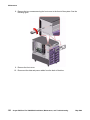
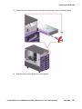
Accessing components inside the computer . . . . . . . . . . . . . . . . . . . . . . .
Opening and removing a side door. . . . . . . . . . . . . . . . . . . . . . . . . . .
Replacing and closing a side door . . . . . . . . . . . . . . . . . . . . . . . . . . .
56
56
58
Using an ESD wrist strap . . . . . . . . . . . . . . . . . . . . . . . . . . . . . . . . . .
59
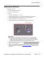
Maintaining PCI cards . . . . . . . . . . . . .
Required references . . . . . . . . . . . .
Precautions . . . . . . . . . . . . . . . .
PCI card configuration . . . . . . . . . .
Reconfiguring PCI network cards . .
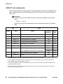
V880 PCI card configuration . . . . .
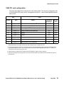
V890 PCI card configuration . . . . .
PCI card compatibility with CMS loads. .
HSI/P X.25 interface card . . . . . . .
GigaSwift four port ethernet card. . .
Maintaining hot-plug PCI cards . . . . . .
PCI slot LEDs for hot-plug operation .
Preparing a hot-plug card for removal
60
60
61
61
61
62
63
64
64
64
65
66
68
4
.
.
.
.
.
.
.
.
.
.
.
.
.
.
.
.
.
.
.
.
.
.
.
.
.
.
.
.
.
.
.
.
.
.
.
.
.
.
.
.
.
.
.
.
.
.
.
.
.
.
.
.
.
.
.
.
.
.
.
.
.
.
.
.
.
.
.
.
.
.
.
.
.
.
.
.
.
.
.
.
.
.
.
.
.
.
.
.
.
.
.
.
.
.
.
.
.
.
.
.
.
.
.
.
.
.
.
.
.
.
.
.
.
.
.
.
.
.
.
.
.
.
.
.
.
.
.
.
.
.
.
.
.
.
.
.
.
.
.
.
.
.
.
.
.
.
.
.
.
.
.
.
.
.
.
.
.
.
.
.
.
.
.
.
.
.
.
.
.
.
.
.
.
.
.
.
.
.
.
.
.
.
.
.
.
.
.
.
.
.
.
.
.
.
.
.
.
.
.
.
.
.
.
.
.
.
.
.
.
.
.
.
.
.
.
.
.
.
.
.
.
.
.
.
.
.
.
.
.
.
.
.
.
.
.
.
.
.
.
.
.
.
.
.
.
.
.
.
.
.
.
.
.
.
.
.
.
.
.
.
.
.
.
.
.
.
.
.
.
.
.
.
.
.
.
.
.
.
.
.
.
.
.
.
.
.
.
.
.
.
.
.
.
.
.
.
.
.
.
.
.
.
.
.
.
.
.
.
.
.
.
.
.
.
.
.
.
.
.
.
.
.
.
.
Avaya CMS Sun Fire V880/V890 Installation, Maintenance, and Troubleshooting
.
.
.
.
.
.
.
.
.
.
.
.
.
.
.
.
.
.
.
.
.
.
.
.
.
.
.
.
.
.
.
.
.
.
.
.
.
.
.
.
.
.
.
.
.
.
.
.
.
.
.
.
.
.
.
.
.
.
.
.
.
.
.
.
.
.
.
.
.
.
.
.
.
.
.
.
.
.
.
.
.
.
.
.
.
.
.
.
.
.
.
.
.
.
.
.
.
.
.
.
.
.
.
.
.
.
.
.
.
.
.
.
.
.
.
May 2006
Contents
Removing a hot-plug PCI card . . . . . . . . . . . . . . . . . .
Installing a hot-plug PCI card . . . . . . . . . . . . . . . . . . .
Configuring the new or replacement card . . . . . . . . . . . .
Replacing the graphics card . . . . . . . . . . . . . . . . . . . . .
Installing the XVR-100 software packages (V880 and R3V11 only)
Replacing SCSI cards . . . . . . . . . . . . . . . . . . . . . . . . .
Maintaining HSI/P cards (R3V11 on V880 only) . . . . . . . . . . .
Replacing an HSI/P card. . . . . . . . . . . . . . . . . . . . . .
Installing the first HSI/P card or a pair of HSI/P cards. . . . . .
Installing HSI/P software and patches . . . . . . . . . . . . . .
Setting up the switch link for each ACD . . . . . . . . . . . . .
Adding a second HSI/P card . . . . . . . . . . . . . . . . . . .
.
.
.
.
.
.
.
.
.
.
.
.
.
.
.
.
.
.
.
.
.
.
.
.
.
.
.
.
.
.
.
.
.
.
.
.
.
.
.
.
.
.
.
.
.
.
.
.
.
.
.
.
.
.
.
.
.
.
.
.
.
.
.
.
.
.
.
.
.
.
.
.
.
.
.
.
.
.
.
.
.
.
.
.
.
.
.
.
.
.
.
.
.
.
.
.
.
.
.
.
.
.
.
.
.
.
.
.
68
71
73
74
78
79
83
83
88
91
91
93
.
.
.
.
.
.
.
.
.
.
.
.
.
.
.
.
.
.
.
.
.
.
.
.
.
.
.
.
.
.
.
.
.
.
.
.
.
.
.
.
.
.
.
.
.
.
.
.
.
.
.
.
.
.
.
.
.
.
.
.
.
.
.
.
.
.
.
.
.
.
.
.
.
.
.
.
.
.
.
.
.
.
.
.
.
.
.
.
.
.
.
.
.
.
.
.
.
.
.
96
96
96
96
98
98
99
105
109
109
116
Replacing the DVD drive . . . . . . . . . . . . . . . . . . . . . . . . . . . . . . . . . .
119
Maintaining tape drives . . . . . . . . . . . . . . . . . . . . . . . . .
Tape drive compatibility. . . . . . . . . . . . . . . . . . . . . . .
Ordering tapes . . . . . . . . . . . . . . . . . . . . . . . . . . . .
Cleaning the tape drive . . . . . . . . . . . . . . . . . . . . . . .
Replacing the internal tape drive . . . . . . . . . . . . . . . . . .
Adding and removing an external tape drive for data migration .
.
.
.
.
.
.
.
.
.
.
.
.
.
.
.
.
.
.
.
.
.
.
.
.
.
.
.
.
.
.
.
.
.
.
.
.
.
.
.
.
.
.
.
.
.
.
.
.
.
.
.
.
.
.
.
.
.
.
.
.
124
124
124
125
126
129
Maintaining CPU/Memory boards. . . . . . . . . . . . . .
CPU and memory configurations . . . . . . . . . . . .
Checking the current memory and CPU configuration
Shutting down the system . . . . . . . . . . . . . . .
Removing a CPU/Memory board . . . . . . . . . . . .
Replacing memory. . . . . . . . . . . . . . . . . . . .
Installing a CPU/Memory board. . . . . . . . . . . . .
Restarting the system . . . . . . . . . . . . . . . . . .
.
.
.
.
.
.
.
.
.
.
.
.
.
.
.
.
.
.
.
.
.
.
.
.
.
.
.
.
.
.
.
.
.
.
.
.
.
.
.
.
.
.
.
.
.
.
.
.
.
.
.
.
.
.
.
.
.
.
.
.
.
.
.
.
.
.
.
.
.
.
.
.
.
.
.
.
.
.
.
.
134
134
135
136
137
138
140
143
Replacing a power supply. . . . . . . . . . . . . . . . . . . . . . . . . . . . . . . . . .
145
Maintaining disk drives . . . . . . . . . . . . . . . . . . . . .
Prerequisites . . . . . . . . . . . . . . . . . . . . . . . . .
Disk drive compatibility with CMS loads . . . . . . . . . .
Disk drive configurations . . . . . . . . . . . . . . . . . .
Required references . . . . . . . . . . . . . . . . . . . . .
Replacing disk drives . . . . . . . . . . . . . . . . . . . .
Replacing a single boot disk or replacing data disks .
Replacing both boot disks . . . . . . . . . . . . . . .
Setting up the disk drives . . . . . . . . . . . . . . . .
Partitioning disk drives . . . . . . . . . . . . . . . . .
Adding disk drives (optional) . . . . . . . . . . . . . . . .
.
.
.
.
.
.
.
.
.
.
.
.
.
.
.
.
.
.
.
.
.
.
.
.
.
.
.
.
.
.
.
.
.
.
.
.
.
.
.
.
.
.
.
.
.
.
.
.
.
.
.
.
.
.
.
.
.
.
.
.
.
.
.
.
.
.
.
.
.
.
.
.
.
.
.
.
.
.
.
.
.
.
.
.
.
.
.
.
.
.
.
.
.
.
.
.
.
.
.
.
.
.
.
Avaya CMS Sun Fire V880/V890 Installation, Maintenance, and Troubleshooting
May 2006
5
Contents
Troubleshooting . . . . . . . . . . . . . . . . . . . . . . . . . . . . . . . . . . . . . . . . .
6
149
Using the remote console . . . . . . . . . . . . . . . . . . . . . .
Redirecting the console using Solaris . . . . . . . . . . . . .
Redirecting the local console to the remote console . . .
Redirecting the remote console back to the local console
Redirecting the console using OpenBoot mode. . . . . . . .
Redirecting the local console to the remote console . . .
Redirecting the remote console back to the local console
.
.
.
.
.
.
.
.
.
.
.
.
.
.
.
.
.
.
.
.
.
.
.
.
.
.
.
.
.
.
.
.
.
.
.
.
.
.
.
.
.
.
.
.
.
.
.
.
.
.
.
.
.
.
.
.
.
.
.
.
.
.
.
.
.
.
.
.
.
.
.
.
.
.
.
.
.
.
.
.
.
.
.
.
150
150
150
152
153
153
154
Tools . . . . . . . . . . . . . . . . . . . . . . . .
Using the prtdiag command . . . . . . . . .
Using the cfgadm command . . . . . . . . .
System messages . . . . . . . . . . . . . . .
OpenBoot PROM firmware tests . . . . . . .
Using the OpenBoot PROM tests . . . . .
Test descriptions . . . . . . . . . . . . .
Probing disk drives . . . . . . . . . . . .
Probing all SCSI media devices. . . . . .
Probing the IDE DVD device (V890 only) .
OpenBoot diagnostic tests . . . . . . . . . .
Test descriptions . . . . . . . . . . . . .
POST diagnostic messages. . . . . . . . . .
Memory failure . . . . . . . . . . . . . . .
OpenBoot initialization commands. . . . . .
Diagnosing status indicators . . . . . . . . .
Front panel status indicators . . . . . . .
PCI slot status indicators . . . . . . . . .
Power supply status indicators . . . . . .
Disk drive status indicators . . . . . . . .
Tape drive status indicators . . . . . . .
Sun Validation Test Suite (VTS) . . . . . . .
Prerequisites . . . . . . . . . . . . . . . .
Using SunVTS . . . . . . . . . . . . . . .
.
.
.
.
.
.
.
.
.
.
.
.
.
.
.
.
.
.
.
.
.
.
.
.
.
.
.
.
.
.
.
.
.
.
.
.
.
.
.
.
.
.
.
.
.
.
.
.
.
.
.
.
.
.
.
.
.
.
.
.
.
.
.
.
.
.
.
.
.
.
.
.
.
.
.
.
.
.
.
.
.
.
.
.
.
.
.
.
.
.
.
.
.
.
.
.
.
.
.
.
.
.
.
.
.
.
.
.
.
.
.
.
.
.
.
.
.
.
.
.
.
.
.
.
.
.
.
.
.
.
.
.
.
.
.
.
.
.
.
.
.
.
.
.
.
.
.
.
.
.
.
.
.
.
.
.
.
.
.
.
.
.
.
.
.
.
.
.
.
.
.
.
.
.
.
.
.
.
.
.
.
.
.
.
.
.
.
.
.
.
.
.
.
.
.
.
.
.
.
.
.
.
.
.
.
.
.
.
.
.
.
.
.
.
.
.
.
.
.
.
.
.
.
.
.
.
.
.
.
.
.
.
.
.
.
.
.
.
.
.
.
.
.
.
.
.
.
.
.
.
.
.
.
.
.
.
.
.
.
.
.
.
.
.
.
.
.
.
.
.
.
.
.
.
.
.
.
.
.
.
.
.
.
.
.
.
.
.
157
158
164
165
166
166
167
168
169
170
172
173
175
175
176
177
177
179
181
182
184
185
185
185
Troubleshooting disk drives and DVD drives . . . . . . . . . . . . . . . . . . . . . . .
186
Troubleshooting tape drives . . . . . . . . . . . . . . . . . . . . . . . . . . . . . . . .
Checking tape status . . . . . . . . . . . . . . . . . . . . . . . . . . . . . . . . . .
Reassigning device instance numbers for tape devices . . . . . . . . . . . . . . .
190
190
192
Recovery procedures . . . . . . . . . . .
Preserving data after a system failure
Loss of power . . . . . . . . . . . . .
Probe command warnings . . . . . .
193
193
194
196
.
.
.
.
.
.
.
.
.
.
.
.
.
.
.
.
.
.
.
.
.
.
.
.
.
.
.
.
.
.
.
.
.
.
.
.
.
.
.
.
.
.
.
.
.
.
.
.
.
.
.
.
.
.
.
.
.
.
.
.
.
.
.
.
.
.
.
.
.
.
.
.
.
.
.
.
.
.
.
.
.
.
.
.
.
.
.
.
.
.
.
.
.
.
.
.
.
.
.
.
.
.
.
.
.
.
.
.
.
.
.
.
.
.
.
.
.
.
.
.
.
.
.
.
.
.
.
.
.
.
.
.
.
.
.
.
.
.
.
.
.
.
.
.
.
.
.
.
.
.
.
.
.
.
.
.
.
.
.
.
.
.
.
.
.
.
.
.
.
.
.
.
.
.
.
.
.
.
.
.
.
.
.
.
.
.
.
.
.
.
.
.
.
.
.
.
.
.
.
.
.
.
.
.
.
.
.
.
.
.
.
.
.
.
.
.
.
.
.
.
.
.
.
.
.
.
.
.
.
.
.
.
.
.
.
.
.
.
.
.
.
.
.
.
.
.
.
.
.
.
.
.
.
.
.
.
.
.
.
.
.
.
.
.
.
.
.
.
.
.
.
.
.
.
.
.
.
.
.
.
.
.
.
.
.
.
.
.
Avaya CMS Sun Fire V880/V890 Installation, Maintenance, and Troubleshooting
.
.
.
.
.
.
.
.
.
.
.
.
.
.
.
.
.
.
.
.
.
.
.
.
.
.
.
.
May 2006
Contents
Reseating HSI/P cards (R3V11 and V880 only) . . . . . . . . . . . . . . . . . . . .
Resetting a device alias . . . . . . . . . . . . . . . . . . . . . . . . . . . . . . . . .
Remote console port problems . . . . . . . . . . . . . . . . . . . . . . . . . . . . .
197
198
200
Glossary
. . . . . . . . . . . . . . . . . . . . . . . . . . . . . . . . . . . . . . . . . . .
203
Index
. . . . . . . . . . . . . . . . . . . . . . . . . . . . . . . . . . . . . . . . . . .
205
Avaya CMS Sun Fire V880/V890 Installation, Maintenance, and Troubleshooting
May 2006
7
Contents
8
Avaya CMS Sun Fire V880/V890 Installation, Maintenance, and Troubleshooting
May 2006
Preface
Avaya Call Management System (CMS) is an application for businesses and organizations that
use Avaya communication servers to process large volumes of telephone calls using the
Automatic Call Distribution (ACD) feature. Avaya CMS supports solutions for routing and agent
selection, multi-site contact centers, remote agents, reporting, interfaces to other systems,
workforce management, desktop applications, system recovery, and quality monitoring.
Avaya CMS is part of the Operational Effectiveness solution of the Avaya Customer Interaction
Suite.
This section includes the following topics:
●
Purpose on page 9
●
Intended users on page 10
●
Overview on page 10
●
Conventions and terminology on page 11
●
Reasons for reissue on page 12
●
Related documentation on page 14
●
Support on page 18
Purpose
Avaya Call Management System Sun Fire V880/V890 Computer Hardware Installation,
Maintenance, and Troubleshooting is written for technicians who install and maintain call center
applications such as Avaya Call Management System (CMS).
Note:
Note:
The Sun Fire V880 computer is compatible with CMS R3V11 and later. The Sun
Fire V890 computer is compatible with CMS R13 and later.
Avaya CMS Sun Fire V880/V890 Installation, Maintenance, and Troubleshooting
May 2006
9
Preface
Intended users
This document is written for:
●
Avaya support personnel
●
Avaya factory personnel
●
Contact center administrators
Users of this document must be familiar with Avaya CMS and the Solaris operating system.
Overview
This document is organized as follows:
10
●
Installation on page 19 - Describes how to assemble the computer, connect external
devices, and turn on the computer.
●
Maintenance on page 49 - Describes how to maintain the computer.
●
Troubleshooting on page 149 - Describes how to troubleshoot the computer.
●
Glossary on page 203
●
Index on page 205
Avaya CMS Sun Fire V880/V890 Installation, Maintenance, and Troubleshooting
May 2006
Conventions and terminology
Conventions and terminology
Unless noted otherwise, the phrase "Sun Fire" used in this document applies to both the Sun
Fire V880 computer and the Sun Fire V890 computer.
If you see any of the following safety labels in this document, take careful note of the information
presented.
!
CAUTION:
Caution statements call attention to situations that can result in harm to software,
loss of data, or an interruption in service.
!
WARNING:
Warning statements call attention to situations that can result in harm to hardware
or equipment.
!
DANGER:
Danger statements call attention to situations that can result in harm to personnel.
!
SECURITY ALERT:
Security alert statements call attention to situations that can increase the potential
for unauthorized use of a telecommunications system.
CAUTION:
WARNING:
DANGER:
SECURITY ALERT:
Avaya CMS Sun Fire V880/V890 Installation, Maintenance, and Troubleshooting
May 2006
11
Preface
Reasons for reissue
The May 2006 version of this document was changed for the following reasons:
●
To make general wording and format corrections.
Issue 3.0 of this document was changed for the following reasons:
●
To add information about the new V890 model of the Sun Fire computer. The V890 is
replacing the V880 model beginning with CMS R13. The V890 includes information about
the following new hardware:
- Quad GigaSwift Ethernet card, single Gigabit Ethernet card, and Dual Ultra320 SCSI
card
- IDE model DVD-ROM
- 146-GB disk drives
●
To add information about CMS R13.
●
To note that the Sun Fire V880 is going from 256-MB DIMMs to 512-MB DIMMs.
●
To update the recommended card layout on the V880 (see Computer layout on page 28
and Maintaining PCI cards on page 60).
●
To make general wording and format corrections.
Issue 2.0 of this document was changed for the following reasons:
12
●
To add information about the new DAT 72 tape drive.
●
To note that X.25 switch links are not supported for CMS R12 and later (see Connecting
the switch link on page 40).
●
To update information that the newer Dual FastEthernet and Dual SCSI card supports hot
plug operation (see Maintaining hot-plug PCI cards on page 65).
●
To update the tape ordering procedures (see Ordering tapes on page 124).
●
To make general wording and format corrections.
Avaya CMS Sun Fire V880/V890 Installation, Maintenance, and Troubleshooting
May 2006
Reasons for reissue
Issue 1.1 of this document was changed for the following reasons:
●
To add information about the new Dual FastEthernet and Dual SCSI card. This card is
replacing the SunSwift card. See the following sections for more information:
- Computer layout on page 28
- Peripheral connectivity on page 36
- Parts list on page 37
- Computer layout on page 51
- PCI card configuration on page 61
●
To update the remote console setup procedure (see Setting the remote console modem
options on page 46).
●
To add a procedure for installing software for the XVR-100 graphic accelerator card (see
Installing the XVR-100 software packages (V880 and R3V11 only) on page 78).
●
To update the tape ordering procedures (see Ordering tapes on page 124).
●
To make general wording and format corrections.
Avaya CMS Sun Fire V880/V890 Installation, Maintenance, and Troubleshooting
May 2006
13
Preface
Related documentation
You might find the following Avaya CMS documentation useful. This section includes the
following topics:
●
Change descriptions on page 14
●
Administration documents on page 14
●
Software documents on page 15
●
Hardware documents on page 15
●
Call Center documents on page 16
●
Avaya CMS upgrade documents on page 16
●
Documentation Web sites on page 18
Change descriptions
For information about recent changes made in Avaya CMS and Avaya Call Center, see:
●
Avaya Call Management System (CMS) Release 13.1 Change Description, 07-600955
●
Avaya Call Center Release 3.1 Change Description, 07-300560
●
Avaya Call Center 3.0 and Call Management System Release 13 Change Description,
07-300304
Administration documents
For more information about Avaya CMS administration, see:
14
●
Avaya Call Management System Release 13 Administration, 07-600956
●
Avaya Call Management System (CMS) Release 13 Database Items and Calculations,
07-300330
●
Avaya Call Management System Supervisor Release 13 Reports, 07-300334
●
Avaya Call Management System (CMS) Supervisor Release 13 Installation and Getting
Started, 07-300333
●
Avaya Call Management System High Availability User Guide, 07-300066
●
Avaya Call Management System High Availability Connectivity, Upgrade and
Administration, 07-600957
Avaya CMS Sun Fire V880/V890 Installation, Maintenance, and Troubleshooting
May 2006
Related documentation
Software documents
For more information about Avaya CMS software, see:
●
Avaya Call Management System Release 13 Software Installation, Maintenance, and
Troubleshooting Guide, 07-600954
●
Avaya CMS Open Database Connectivity Version 4.2, 585-780-701
●
Avaya Call Management System Release 13 LAN Backup User Guide, 07-600953
●
Avaya Call Management System Release 13 External Call History Interface, 07-300737
●
Avaya CMS Custom Reports, 585-215-822
●
Avaya CMS Forecast User Guide, 585-215-825
●
Avaya Visual Vectors Release 13 Installation and Getting Started, 07-300353
●
Avaya Visual Vectors Release 13 User Guide, 07-300354
●
Avaya Call Management System (CMS) Supervisor Release 13 Report Designer,
07-300743
Hardware documents
For more information about Avaya CMS hardware, see:
●
Avaya Call Management System Sun Netra 210 Computer Hardware Installation,
Maintenance, and Troubleshooting, 07-600963
●
Avaya Call Management System Sun Fire V880/V890 Computer Hardware Installation,
Maintenance, and Troubleshooting, 07-600965
●
Avaya Call Management System Sun Blade 100/150 Workstation Hardware Installation,
Maintenance, and Troubleshooting, 07-600964
●
Avaya Call Management System Terminals, Printers, and Modems, 585-215-874
Avaya CMS Sun Fire V880/V890 Installation, Maintenance, and Troubleshooting
May 2006
15
Preface
Call Center documents
For more information about Avaya Call Center documents, see:
●
Avaya Communication Manager Call Center Software Basic Call Management System
(BCMS) Operations, 07-300061
●
Avaya Call Center Call Vectoring and Expert Agent Selection (EAS) Guide, 07-300477
●
Avaya Call Center Automatic Call Distribution (ACD) Guide, 07-300478
●
Avaya Business Advocate User Guide, 07-300653
●
Avaya Call Management System Switch Connections, Administration, and
Troubleshooting, 07-300739
Avaya CMS upgrade documents
There are several upgrade paths supported with Avaya CMS. There is a document designed to
support each upgrade.
This section includes the following topics:
●
Base load upgrades on page 16
●
Platform upgrades and data migration on page 17
●
Avaya Call Management System Upgrade Express (CUE) on page 17
Base load upgrades
Use a base load upgrade when upgrading CMS to the latest load of the same version (for
example, r13ak.g to r13al.k). A specific set of instructions is written for the upgrade. The
instructions are shipped to the customer site with the CMS software CD-ROM as part of a
Product Correction Notice (PCN).
For more information about base load upgrades, see:
●
16
Avaya Call Management System Release 13 Base Load Upgrade
Avaya CMS Sun Fire V880/V890 Installation, Maintenance, and Troubleshooting
May 2006
Related documentation
Platform upgrades and data migration
Use a platform upgrade when upgrading to a new hardware platform (for example, upgrading
from a SPARCserver 5 to a Sun Netra 210). The new hardware platform is shipped from the
Avaya factory with the latest CMS load. Therefore, as part of the upgrade you will have the
latest CMS load (for example, R3V9 to R13).
For more information about platform upgrades and data migration, see:
●
Avaya Call Management System Release 13 Platform Upgrade and Data Migration,
07-600968
Avaya Call Management System Upgrade Express (CUE)
Use CUE when CMS is being upgraded from an earlier version (for example, R3V9) to the latest
version (for example, R13).
A specific set of upgrade instructions is written for the upgrade. These instructions are included
on the CUE software CD-ROM that is shipped to the customer site with the CUE kit.
For information about customer requirements for CUE upgrades, see:
●
Avaya Call Management System Release 13 CMS Upgrade Express (CUE) Customer
Requirements, 700356744
For information about CUE upgrade procedures, see:
●
Avaya Call Management System Release 13.1 Sun Blade 100/150 Workstation Mirrored
and Nonmirrored Systems CMS Upgrade Express (CUE), 07-600763
●
Avaya Call Management System Release 13.1 Sun Fire V880/V890 Computer CMS
Upgrade Express (CUE), 07-600764
Avaya CMS Sun Fire V880/V890 Installation, Maintenance, and Troubleshooting
May 2006
17
Preface
Documentation Web sites
For Avaya product documentation, go to http://www.avayadocs.com. Additional information
about new software or hardware updates will be contained in future issues of this book. New
issues of this book will be placed on the Web site when available.
Use the following Web sites to view related support documentation:
●
Information about Avaya products and service
http://www.avaya.com
●
Sun hardware documentation
http://docs.sun.com
●
Informix documentation
http://www.informix.com
●
Tivoli Storage Manager documentation
http://www.tivoli.com
Support
Contacting Avaya technical support
Avaya provides support telephone numbers for you to report problems or ask questions about
your product.
For United States support:
1- 800- 242-2121
For international support:
See the 1-800 Support Directory listings on the Avaya Web site.
Escalating a technical support issue
Avaya Global Services Escalation Management provides the means to escalate urgent service
issues. For more information, see the Escalation Management listings on the Avaya Web site.
18
Avaya CMS Sun Fire V880/V890 Installation, Maintenance, and Troubleshooting
May 2006
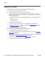
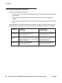
Installation
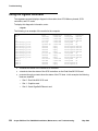
This section describes how to install the computer and related peripheral equipment. Use the
following table to check off each required procedure after completion.
Procedure
Completed
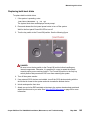
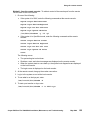
Preparing for installation on page 20
Unpacking and inventorying the equipment on page 25
Setting up power on page 35
Peripheral connectivity on page 36
Connecting the monitor, keyboard, and mouse on page 38
Connecting the remote console modem on page 39
Connecting to external interfaces:
●
Connecting the switch link on page 40
●
Connecting to the customer network on page 40
Turning on the system and verifying POST on page 41
Identifying installed PCI cards on page 44
Setting the remote console modem options on page 46
Turning the system over for provisioning on page 48
Avaya CMS Sun Fire V880/V890 Installation, Maintenance, and Troubleshooting
May 2006
19
Installation
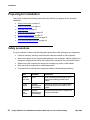
Preparing for installation
This section contains the following information that will help you prepare for the computer
installation:
●
Safety precautions on page 20
●
System precautions on page 21
●
Required tools on page 22
●
Electrical specifications on page 22
●
Physical specifications on page 23
●
Service access specifications on page 23
●
Environmental specifications on page 24
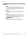
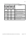
Safety precautions
For your protection, observe the following safety precautions when setting up your equipment:
20
●
Follow all cautions, warnings, and instructions that are marked on the equipment.
●
Never push objects of any type through openings in the equipment. Objects might touch
dangerous voltage points or short out components, resulting in fire or an electric shock.
●
When moving the computer, be careful not to unplug any power or data cables.
●
Refer servicing of equipment to qualified personnel.
●
To protect both yourself and the equipment, observe the following precautions.
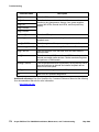
Item
Problem
Precaution
Wrist or
foot strap
ESD
Wear a conductive wrist strap or foot
strap when handling printed circuit
boards.
Cover
panels
System
damage and
overheating
Reinstall all cabinet cover panels after
you perform any service work on the
system.
Card slot
filler
panels
System
damage and
overheating
Ensure that a filler panel is installed on
all empty card slots.
Avaya CMS Sun Fire V880/V890 Installation, Maintenance, and Troubleshooting
May 2006
Preparing for installation
System precautions
Ensure that the voltage and frequency of the power outlet that is used matches the electrical
rating labels on the equipment.
Wear antistatic wrist straps when handling any magnetic storage devices, CPU/Memory boards,
or other printed circuit boards.
The V880 computer has three autoranging power supplies that use nominal input voltages
of 100 to 240 V AC at 47 to 63 Hz. The V890 computer has three autoranging power supplies
that use nominal input voltages of 200 to 240 V AC at 47 to 63 Hz.
!
WARNING:
WARNING:
You cannot interchange power supplies between a V880 and V890 computer.
Sun products are designed to work with single-phase power systems that have a grounded
neutral conductor. To reduce the risk of electrical shock, do not plug Sun products into another
type of power source. Contact your facilities manager or qualified electrician if you are unsure of
what type of power is supplied to your building.
Avaya recommends that you use one of the following power schemes:
●
For a V880, use two (2) 2KVA Uninterruptible Power Supplies (UPS) (or equivalent), each
powered by a nonswitched, dedicated, 15-amp circuit. Connect two of the power supplies
to one UPS, and the third power supply to the second UPS. The monitor and external
peripherals can also be connected to the second UPS.
●
For a V890, use one 6KVA UPS (or equivalent), powered by a nonswitched,
dedicated, 15-amp circuit. Connect all of the power supplies to the UPS. The monitor and
external peripherals can also be connected to the UPS.
Note:
If not using a UPS, connect each power supply to a nonswitched,
dedicated, 15-amp circuit. Connect the monitor and external peripherals to a
separate circuit.
Note:
Each of the following items require a separate power cord:
●
Power supplies in the computer (3 power cords)
●
External peripherals
●
Monitor
!
WARNING:
WARNING:
Do not make mechanical or electrical modifications to the cabinet. Sun
Microsystems is not responsible for regulatory compliance of modified cabinets.
Avaya CMS Sun Fire V880/V890 Installation, Maintenance, and Troubleshooting
May 2006
21
Installation
Required tools
You need the following tools to do the installation:
●
Phillips #2 screwdriver
●
ESD grounding wrist strap
●
Antistatic mat
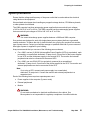
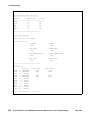
Electrical specifications
Parameter
Value
V880
Input
● Nominal voltage range
● Maximum current AC RMS
● AC operating range
● Nominal frequencies
●
●
●
●
100-240 V AC,
autoranging
15.0 A @100 VAC
90-264 V rms, 47-63Hz
50 Hz or 60 Hz
V890
●
●
●
●
200-240 V AC,
autoranging
8.0 A @200 VAC
180-264 V rms, 47-63Hz
50 Hz or 60 Hz
Maximum DC power output
2240 W
2509 W
Maximum system AC power
consumption
3000 W
3200 W
Maximum system heat dissipation
10308 BTU/hr
10912 BTU/hr
Volt-ampere rating
1515 VA with 1120 Watt load
(PF=0.99)
2078 VA with 1629 Watt load
(PF=0.98)
Wall plug type
● United States
● Non-United States
●
CPU plug type
IEC 320
22
●
NEMA 5-15P
Power cords must be
obtained locally
●
●
NEMA 6-15P
Power cords must be
obtained locally
IEC 320
Avaya CMS Sun Fire V880/V890 Installation, Maintenance, and Troubleshooting
May 2006
Preparing for installation
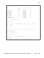
Physical specifications
Parameter
English value
Metric value
Height (with casters)
28.1 inches
71.4 centimeters
Width
18.9 inches
48.0 centimeters
Depth
32.9 inches
83.6 centimeters
Weight (min-max)1
194-288 pounds
88-130.6 kilograms
Power cords
8.2 feet
2.5 meters
1. The actual weight depends on the installed options.
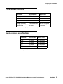
Service access specifications
Parameter
English value
Metric value
Front1
36 inches
91 centimeters
Rear
36 inches
91 centimeters
Left
36 inches
91 centimeters
Right
36 inches
91 centimeters
1. 48 inches (122 centimeters) for rack mounted
systems.
Avaya CMS Sun Fire V880/V890 Installation, Maintenance, and Troubleshooting
May 2006
23
Installation
Environmental specifications
For the most reliable system operation:
●
The room must have sufficient air conditioning capacity to support the cooling needs of the
entire system.
●
The air conditioning system must have controls that prevent excessive temperature
changes.
●
Do not turn on the computer until it has acclimated to the room temperature for at least 24
hours.
Use the guidelines in the following table for temperature, humidity, and altitude limits for units in
operation and for units that are not in operation (that is, units that are in transit or in storage).
24
Parameter
Operating
(in service)
Nonoperating
(not in service)
Temperature
41°F to 95°F (5°C to 35°C)
IEC 68-2-2, 68-2-3
-4°F to 140°F (-20°C to 60°C)
IEC 68-2-2, 68-2-3
Humidity
(max)
20% to 80% RH
noncondensing at 27°C max wet bulb
IEC 68-2-2, 68-2-3
95% RH
noncondensing at 40°C
IEC 68-2-2, 68-2-3
Altitude (max)
10,000 feet (3 kilometers)
IEC 68-2-40, 68-2-41
40,000 feet (12 kilometers)
IEC 68-2-40, 68-2-41
Avaya CMS Sun Fire V880/V890 Installation, Maintenance, and Troubleshooting
May 2006
Unpacking and inventorying the equipment
Unpacking and inventorying the equipment
!
WARNING:
Never move the system when the power is on. Excessive movement can cause
catastrophic disk drive failure. Always turn off the power before moving cabinets.
!
WARNING:
Always wear an electrostatic discharge (ESD) wrist strap when handling internal
components.
!
CAUTION:
Always have up-to-date system backups before turning the computer off and
moving the computer.
WARNING:
WARNING:
CAUTION:
Inspect all shipping cartons for evidence of physical damage. If a shipping carton is damaged,
request that the carrier representative be present before the carton is opened.
Unpack the computer and the associated peripheral equipment. Compare the contents of the
carton to the shipping inventory list to verify that all equipment was delivered.
In the United States, contact Avaya technical support if any parts are defective on arrival.
Contact Avaya customer service if any parts are missing.
Outside the United States, contact your Avaya representative or distributor if any parts are
missing or defective.
This section includes the following topics:
●
Parts list on page 26
●
Determining the computer model on page 27
●
Computer layout on page 28
●
Hardware options on page 33
●
Rack mounting on page 34
Avaya CMS Sun Fire V880/V890 Installation, Maintenance, and Troubleshooting
May 2006
25
Installation
Parts list
Verify that you have the following components before you start the installation:
!
Important:
Note:
26
Important:
DO NOT install internal hardware shipped loose with the Sun computer at this
time. This is done under the direction of a CMS Provisioning engineer at a
scheduled appointment time.
●
Sun Fire cabinet, including installed cards and disk drives
●
Computer power cords (3)
●
Monitor, cable, and monitor AC power cord
●
USB keyboard and cable
●
USB mouse and cable
●
A package of blank tapes for backups
●
One tape that contains the Avaya factory configuration CMSADM filesystem backup
●
Category 5 LAN cable
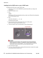
●
Modem and cables
●
Keys
●
Sun and CMS software
Note:
CMS computers do not ship with tape drive cleaning tapes. Avaya recommends
that customers purchase at least one cleaning tape as soon as the computer is
installed and in service.
Avaya CMS Sun Fire V880/V890 Installation, Maintenance, and Troubleshooting
May 2006
Unpacking and inventorying the equipment
Determining the computer model
This book is written for use with several different models of the Sun Fire computer. The
differences between the models are few. This section shows how to identify the different
models.
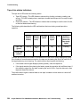
Features
Each of the different models have distinctive features that will also assist you in determining
what model you have.
V880 Model 1: 900 MHz UltraSparc III CPUs, 256-MB DIMMs, 73-GB 10K rpm disks, SCSI
DVD-ROM drive, DDS-4 SCSI tape drive, 120 or 220 volt AC
V880 Model 2: 1.2 GHz UltraSparc III CPUs, 256-MB DIMMs, 73-GB 10K rpm disks, SCSI
DVD-ROM drive, DAT 72 SCSI tape drive, 120 or 220 volt AC
V880 Model 3: 1.2 GHz UltraSparc III CPUs, 512-MB DIMMs, 73-GB 10K rpm disks, SCSI
DVD-ROM drive, DAT 72 SCSI tape drive, 120 or 220 volt AC
V890 Model 1: 1.35 GHz UltraSparc IV CPUs, 146-GB 10K rpm disks, IDE DVD-ROM drive,
DAT 72 SCSI tape drive, 220 volt AC only
Physical labeling
All models are labeled on the front as Sun Fire 880, Sun Fire V880, or Sun Fire V890.
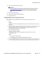
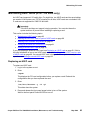
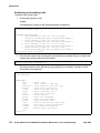
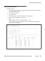
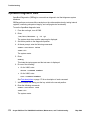
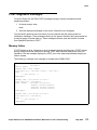
Software check
To determine the model of the computer once the computer is operational:
1. Log in as root.
2. Enter:
prtconf -vp | grep banner-name
V880 Models 1, 2, and 3: The following message is displayed:
banner-name:
'Sun Fire 880'
V890 Model 1: The following message is displayed:
banner-name:
'Sun Fire V890'
Avaya CMS Sun Fire V880/V890 Installation, Maintenance, and Troubleshooting
May 2006
27
Installation
Computer layout
Familiarize yourself with the layout of the computer. The minimum configuration for the
computer depends on the model.
The layout of the V880 is as follows:
●
One CPU/Memory board with two UltraSPARC lIl processors and 4-GB total memory
●
Four 73-GB disk drives, mirrored two plus two (optionally, a third pair of disks can be
added to support the AUX 100 software load)
●
One built-in ethernet port
●
One of the following SCSI/ethernet cards:
- SunSwift card installed in slot 2, or
- Dual FastEthernet and Dual SCSI card installed in slot 2
!
Important:
Important:
On earlier versions of the V880, the ethernet cards were installed in the following
order:
Slots 0, 1, 2, and 5
Avaya now recommends that ethernet cards be installed in the following order:
Slots 2, 1, 6, and 5
See V880 PCI card configuration on page 62 for more information.
28
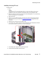
●
One graphics PCI card installed in slot 7
●
Three power supplies and power cords
●
One DVD-ROM drive
●
One tape drive
●
Two USB ports
●
One serial port
Avaya CMS Sun Fire V880/V890 Installation, Maintenance, and Troubleshooting
May 2006
Unpacking and inventorying the equipment
The layout of the V890 is as follows:
●
One CPU/Memory board with two UltraSPARC IV processors and 8-GB total memory
●
Four 146-GB disk drives, mirrored two plus two
●
One built-in ethernet port
●
One Dual Ultra320 SCSI card installed in slot 0
●
One graphics card installed in slot 1
●
One Quad GigaSwift ethernet card installed in slot 6
●
Three power supplies and power cords
●
One DVD-ROM drive
●
One tape drive
●
Two USB ports
●
One serial port
Avaya CMS Sun Fire V880/V890 Installation, Maintenance, and Troubleshooting
May 2006
29
Installation
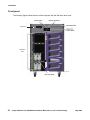
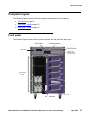
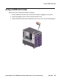
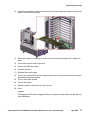
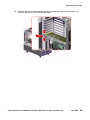
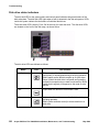
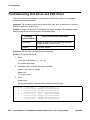
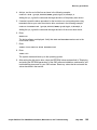
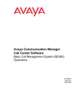
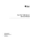
Front panel
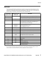
The following figure shows the front of the computer with the disk drive door open.
Tape drive
Disk drive
slots
v880_front.cdr
30
Avaya CMS Sun Fire V880/V890 Installation, Maintenance, and Troubleshooting
May 2006
Unpacking and inventorying the equipment
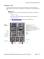
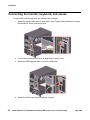
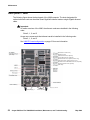
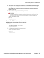
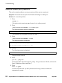
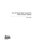
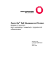
Back panel - V880
The following figure shows the back panel of the V880 computer. The slots designated for
optional ethernet cards can house the FastEthernet, Quad GigaSwift, or single Gigabit ethernet
cards.
!
Important:
Important:
On earlier versions of the V880, the ethernet cards were installed in the following
order:
Slots 0, 1, 2, and 5
Avaya now recommends that ethernet cards be installed in the following order:
Slots 2, 1, 6, and 5
See V880 PCI card configuration on page 62 for more information.
(Reserved for future use)
(Graphics card)
(Third ethernet card, optional)
(Fourth ethernet card, optional)
(Second HSI/P card, optional, R3V11 only)
(First HSI/P card, optional, R3V11 only)
(SunSwift or Dual SCSI/Ethernet card, required)
(Second ethernet card, optional)
(Not used)
(not used)
Power supply 1
Power cord
strain relief ties
v880_rear_cards.cdr
Avaya CMS Sun Fire V880/V890 Installation, Maintenance, and Troubleshooting
May 2006
31
Installation
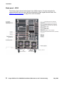
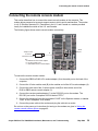
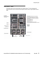
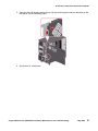
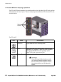
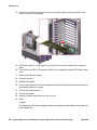
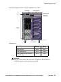
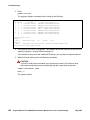
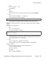
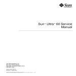
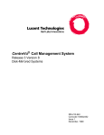
Back panel - V890
The following figure shows the back panel of the V890 computer. The slots designated for
optional ethernet cards can house the Quad GigaSwift or single Gigabit ethernet cards. See
V890 PCI card configuration on page 63 for more information.
(Third ethernet card, optional)
(Fourth ethernet card, optional)
(Quad GigaSwift card, required)
(Second ethernet card, optional)
(Not used)
(Not used)
(Not used)
(Graphics card, required)
(Dual Ultra320 SCSI card, required)
(not used)
ALOM card
Power supply 1
32
Power cord
strain relief ties
V890_rear_cards.cdr
Avaya CMS Sun Fire V880/V890 Installation, Maintenance, and Troubleshooting
May 2006
Unpacking and inventorying the equipment
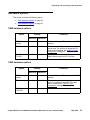
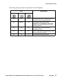
Hardware options
This section includes the following topics:
●
V880 hardware options on page 33
●
V890 hardware options on page 33
V880 hardware options
.
Option
Quantity
Comments
Minimum
Maximum
CPU/Memory
boards
1
4
Each board has two CPU modules and 4-GB
memory.
PCI I/O cards
2
7
There are nine slots, but only seven slots
can be used. For a listing of where the PCI
cards can be installed, see V880 PCI card
configuration on page 62.
Disk drives
(73-GB)
4
6
A pair of data disks can be added to the
system when using the AUX 100 load.
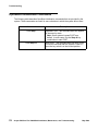
V890 hardware options
.
Option
Quantity
Comments
Minimum
Maximum
CPU/Memory
boards
1
2
Each board has two CPU modules and 8-GB
memory.
PCI I/O cards
2
6
There are nine slots, but only six slots can be
used. For a listing of where the PCI cards
can be installed, see V890 PCI card
configuration on page 63.
Disk drives
(146-GB)
4
4
Avaya CMS Sun Fire V880/V890 Installation, Maintenance, and Troubleshooting
May 2006
33
Installation
Rack mounting
The computer can be rack mounted. For information about rack mounting, see Sun Fire 880
Server Rackmounting Guide or Sun Fire V890 Server Rackmounting Guide at the Sun
documentation Web site:
http://docs.sun.com
When rack mounting the computer, the technician must remove the following components as
described in the rack mounting guide:
34
●
all CPU/Memory boards
●
all power supplies
●
all CPU fan trays
●
all I/O fan trays
Avaya CMS Sun Fire V880/V890 Installation, Maintenance, and Troubleshooting
May 2006
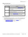
Setting up power
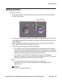
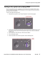
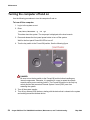
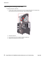
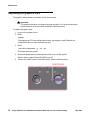
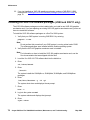
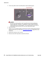
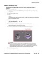
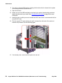
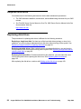
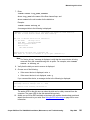
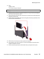
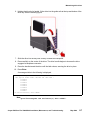
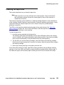
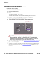
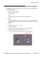
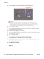
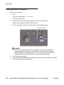
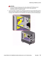
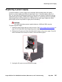
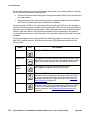
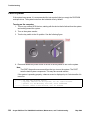
Setting up power
To set up the AC power:
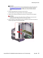
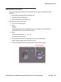
1. Locate the key switch, insert the key, and turn the key switch to the Forced Off position.
See the following figure.
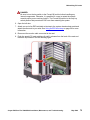
2. Connect the IEC 320 end of each power cord to the AC connector of each power supply.
For installations outside the United States and Canada, obtain three power cords for your
local configuration.
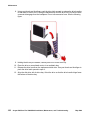
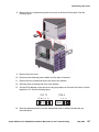
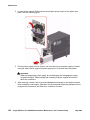
3. Route the power cord through the strain-relief tie-wrap loop located to the right of the
supply. Tighten the tie-wrap to secure the connection.
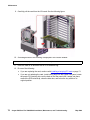
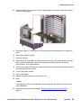
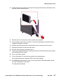
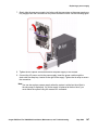
4. Connect the power using one of the following schemes:
Note:
●
For a V880, use two (2) 2KVA Uninterruptible Power Supplies (UPS) (or equivalent),
each powered by a nonswitched, dedicated, 15-amp circuit. Connect two of the power
supplies to one UPS, and the third power supply to the second UPS. The monitor and
external peripherals can also be connected to the second UPS.
●
For a V890, use one 6KVA UPS (or equivalent), powered by a nonswitched,
dedicated, 15-amp circuit. Connect all of the power supplies to the UPS. The monitor
and external peripherals can also be connected to the UPS.
Note:
If not using a UPS, connect each power supply to a nonswitched,
dedicated, 15-amp circuit. Connect the monitor and external peripherals to a
separate circuit.
!
Important:
Important:
Do not turn on power at this time.
Avaya CMS Sun Fire V880/V890 Installation, Maintenance, and Troubleshooting
May 2006
35
Installation
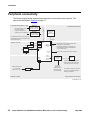
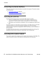
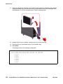
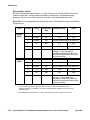
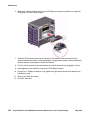
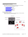
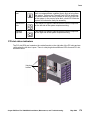
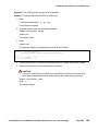
Peripheral connectivity
The following figure shows in general how equipment is connected to the computer. The
callouts are described in Parts list on page 37.
X.25 switch links (R3V11 only)
External SCSI devices
Black Box
C
RS-449 - RS-232
interface converter
One HSI/P card is used
for up to four ACDs.
A second HSI/P card is
needed for five to eight ACDs.
B
Black Box
C
RS-449 - RS-232
interface converter
For detailed switch link connectivity, see
CMS Switch Connections, Administration,
and Troubleshooting
System console
A
L
M Monitor
K
D
SCSI or
Ethernet
SCSI/Ethernet
port
card
USB
port
Keyboard
SCSI port
HSI/P
card
USB
port
P Mouse
O
External SCSI
tape drive
for data
migration only
Graphics
card
Ethernet
card
N
E
Ethernet port for R7 and later switch links
(supports up to eight ACDs)
For detailed switch link connectivity, see
CMS Switch Connections, Administration,
and Troubleshooting
Optional ethernet port (two cards maximum)
AC power
Serial
Port A
Built-in
TPE Fast
Ethernet
Interface
F
Network
hub
To serial terminals, printers, and
modems (R3V11 and earlier; R12
and later, permissive use only)
G
Required telephone
line to remote
maintenance center
Remote console
J
Modem
I
H
NTS
To customer
network for
CMS Supervisor,
network printers,
and LAN backup
For detailed network hub and NTS
connectivity, see CMS Terminals,
Printers, and Modems
Ethernet LAN connections
sunfire880conn.cdr
36
Avaya CMS Sun Fire V880/V890 Installation, Maintenance, and Troubleshooting
May 2006
Parts list
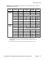
Parts list
The following table lists the parts that are required to connect most external devices to the
computer. For information about switch connections for CMS, see Avaya Call Management
System Switch Connections, Administration, and Troubleshooting.
Connectivity
diagram call out
Material ID or part
of Material ID
A1
408128288
B1
Description
HSI/P card (V880 only; up to two may be installed)
HSI/P quad cable (V880 only; 1 per HSI/P card)
C
407086818
D
N/A2
E1
700230105
700397599
700362403
FastEthernet 10/100 Mbps card (V880 only), or
Quad GigaSwift Ethernet card, or
Single Gigabit Ethernet card
F
407086826
Category 5 UTP cable (10 feet, 3 meters)
G
846362754
DB25-to-RJ45 ACU modem adapter
H
846983039
10-wire modular cord (10 feet, 3 meters)
I
846362770
RJ45-to-DB25 remote console adapter
J
407633999
Varies
Sportster Model 839 33.6 remote console modem
Comsphere 3910 remote console modem
K1
N/A2
Graphics card
L1
N/A2
Monitor cable
M1
N/A2
Monitor
N1
N/A2
Monitor AC power cord
O1
N/A2
USB keyboard with cable
P1
RS-449 cable (V880 only; 10 feet, 3 meters)
SunSwift card (V880 only), or
Dual FastEthernet and Dual SCSI card (V880 only), or
Dual Ultra320 SCSI card (V890 only)
USB mouse with cable
1. Sun Microsystems provides maintenance sparing for these parts.
2. The comcode for this bundle changes regularly and may not be ordered for maintenance spares, so it is not
listed in the table. This bundle includes the processor, peripherals, and other equipment.
Avaya CMS Sun Fire V880/V890 Installation, Maintenance, and Troubleshooting
May 2006
37
Installation
Connecting the monitor, keyboard, and mouse
To connect the monitor, keyboard, and mouse to the computer:
1. Attach the monitor video cable to the graphics card. Tighten the thumbscrews to secure
the connection. See the following figure.
2. Connect the monitor power cord to an approved AC power outlet.
3. Attach the USB keyboard cable to one of the USB ports.
4. Attach the USB mouse cable to the other USB port.
38
Avaya CMS Sun Fire V880/V890 Installation, Maintenance, and Troubleshooting
May 2006
Connecting the remote console modem
Connecting the remote console modem
This section describes how to connect the remote console modem to the computer. This
modem allows personnel at a remote support center to dial in and do maintenance. The modem
is a U.S. Robotics Sportster 33.6 Faxmodem in the U.S. and Canada or a modem provided
locally for installations outside of the U.S. and Canada.
The following figure shows remote console modem connectivity.
.
Telephone line
to remote
maintenance center
C
Modem
Serial
port
B
A
Key:
A = DB25-RJ45 ACU modem adapter
B = 10-wire modular cord
C = RJ45-DB25 remote console adapter
remote_console.cdr
To connect the remote console modem:
1. Connect the DB25-to-RJ45 ACU modem adapter (A) to the serial port on the back of the
computer.
2. Connect the 10-wire modular cord (B) to the modular end of the ACU modem adapter (A).
3. Connect the other end of the 10-wire modular cord (B) to the modular end of the
RJ45-to-DB25 remote console adapter (C).
4. Connect the remote console adapter (C) to the RS-232C port on the modem. The
RS-232C port on the Comsphere 3910 is labeled "DTE1."
5. Connect the telephone line to the jack labeled "LINE" on the Sportster modem, or labeled
"DIAL" on the Comsphere 3910 modem.
6. Connect the power cable to the modem and plug the cable into a socket.
Do not turn on the power yet. Instructions for turning on the modem are given in Setting the
remote console modem options on page 46.
Avaya CMS Sun Fire V880/V890 Installation, Maintenance, and Troubleshooting
May 2006
39
Installation
Connecting to external interfaces
This section describes the external interfaces connected to the computer. This section includes
the following topics:
●
Connecting the switch link on page 40
●
Connecting to the customer network on page 40
Connecting the switch link
Use either of the following two ways to connect the CMS computer to a switch:
●
TCP/IP over a dedicated local area network (LAN) segment. A LAN connection is
supported for R7 and later switch releases, and is required for CMS R12 and later.
●
X.25 protocol over a hard-wired or switched link. This is not supported for CMS R12 and
later.
One CMS computer can collect data from several switches. To the CMS computer, each switch
represents one ACD. You can have all switches connected using TCP/IP, all switches
connected using X.25 protocol (not supported for CMS R12 and later), or some combination of
the two protocols.
For detailed information about how to connect and administer the switch link, see Avaya Call
Management System Switch Connections, Administration, and Troubleshooting.
Connecting to the customer network
The computer supports built-in ethernet ports that support network speeds of 10/100 Mbps. This
ethernet connection is used for CMS Supervisor, network printers, and LAN backup.
40
Avaya CMS Sun Fire V880/V890 Installation, Maintenance, and Troubleshooting
May 2006
Turning on the system and verifying POST
Turning on the system and verifying POST
Once you assemble the system, including the loose hardware that is shipped with the system
that you installed with help from CMS Provisioning, turn on the system and verify the results of
the Power-On Self Test (POST).
To turn on the system and verify POST:
1. Verify that the key switch is in the Forced Off position. See the following figure.
2. If using one or more UPSs, plug the power cord of each UPS into a dedicated circuit. If not
using a UPS, plug the power cords for each power supply into an outlet on a dedicated
15-amp circuit.
3. Turn on the power to the UPS units, if UPS units are installed.
4. Turn on the system monitor.
5. Turn the key switch to the normal On position. See the following figure.
Avaya CMS Sun Fire V880/V890 Installation, Maintenance, and Troubleshooting
May 2006
41
Installation
6. Press and release the power button to the left of the key switch to turn on the system.
Note:
Note:
The POST diagnostics occur each time that you turn on the system. The POST
diagnostics test the basic system components and can take several minutes.
While the system turns on, the power LED on the monitor flashes.
7. Press Stop+A simultaneously as soon as the monitor power LED lights steadily and the
Sun logo is displayed on the monitor.
The ok prompt is displayed.
8. Enter the following commands:
setenv auto-boot? false
reset-all
The system resets to the ok prompt.
9. Enter:
probe-scsi-all
This command verifies that the system sees the disk drives and backplane, the tape drive,
and the DVD drive (SCSI model in V880). A message that is similar to the following
example is displayed:
/pci@8,600000/SUNW,qlc@2
LiD HA LUN --- Port WWN --0
0
0 21000004cf72f08f
1
1
0 21000004cf721553
6
6
0 508002000016b5b1
3
3
0 21000004cf72114b
4
4
0 21000004cf7211ae
-----Disk description ----SEAGATE ST373405FSUN3660438
SEAGATE ST373405FSUN3660438
SUNW
SUNWGS INT FCBPL9224
SEAGATE ST373405FSUN3660438
SEAGATE ST373405FSUN3660438
/pci@8,700000/scsi@1
Target 5
Unit 0
Removeable Tape
HP
C7438A
V309
Target 6
Unit 0
Removeable Read Only device TOSHIBA DVD-ROM SD-M14011009
/pci@8,700000/pci@5/SUNW,1sptwo@4
10. Verify that all the devices are recognized. If the devices are not recognized, see
Troubleshooting disk drives and DVD drives on page 186 for more information.
42
Avaya CMS Sun Fire V880/V890 Installation, Maintenance, and Troubleshooting
May 2006
Turning on the system and verifying POST
11. Enter:
probe-ide
This verifies that the system sees the DVD drive (IDE model in V890). A message that is
similar to the following example is displayed:
Device 0 ( Primary Master )
Removeable ATAPI Model: TOSHIBA DVD-ROM SD-M1712
Device 1 ( Primary Slave )
Not Present
12. Verify that the DVD is recognized. If it is not recognized, see Troubleshooting disk drives
and DVD drives on page 186 for more information.
13. When you have verified that the system recognizes all its devices, enter the following
commands:
!
CAUTION:
CAUTION:
If you fail to reset the auto-boot option, any reboots that you do in the future will
stop at the boot prompt instead of proceeding through the normal boot-up
process.
setenv auto-boot? true
boot
The system reboots.
14. Turn the key switch to the Locked position. Keeping the switch in the Locked position
prevents anyone from accidentally turning off the system. See the following figure.
Avaya CMS Sun Fire V880/V890 Installation, Maintenance, and Troubleshooting
May 2006
43
Installation
Identifying installed PCI cards
If there are problems with the PCI cards, do the following to troubleshoot the problem. If all PCI
cards are operational, you can skip this procedure.
At the command prompt, enter:
/usr/platform/‘uname -m‘/sbin/prtdiag -v | pg
In the section IO Cards, there is a listing of the PCI cards. The following examples are some of
the entries you might see. The display you see depends on your specific configuration.
.
.
========================= IO Cards =========================
Bus Max
IO
Port Bus
Freq Bus Dev,
Type ID Side Slot MHz Freq Func State Name
Brd
Model
---- ---- ---- ---- ---- ---- ---- ---I/O PCI
8
B
1
33
33 4,0
I/O PCI
8
B
0
33
33 5,0
I/O PCI
8
B
0
33
33 5,1
I/O PCI
9
B
6
33
33 2,0
I/O PCI
9
B
6
33
33 0,0
I/O PCI
9
B
6
33
33 0,0
I/O PCI
9
B
6
33
33 1,0
I/O PCI
9
B
6
33
33 4,0
I/O PCI
9
B
6
33
33 2,0
I/O PCI
9
B
6
33
33 3,0
.
.
----ok
ok
ok
ok
ok
ok
ok
ok
ok
ok
-----------------------------------------------------SUNW,XVR-100 SUNW,375-3181
scsi-pci1000,30.1000.10c0.7/disk+LSI,1030
scsi-pci1000,30.1000.10c0.7/disk+LSI,1030
pci-pci8086,b154.0/pci (pci) PCI-BRIDGE
pci-pci8086,b154.0/network (netw+ pci-bridge/pci-bridge
network-pci100b,35.30 SUNW,pci-qge/pci-bridg+
network-pci100b,35.30 SUNW,pci-qge/pci-bridg+
pci-pci8086,b154.0/network (netw+ pci-bridge/pci-bridge
network-pci100b,35.30 SUNW,pci-qge/pci-bridg+
network-pci100b,35.30 SUNW,pci-qge/pci-bridg+
In this example:
44
●
Slot 0 has a Dual Ultra320 SCSI card. There are two entries for a this card because the
card has two SCSI ports.
●
Slot 1 has a graphics card.
●
Slot 6 has a Quad GigaSwift Ethernet card. There is more than one entry for this card
because the card has four ethernet ports.
Avaya CMS Sun Fire V880/V890 Installation, Maintenance, and Troubleshooting
May 2006
Identifying installed PCI cards
You can also use the cfgadm command to display the following information about the cards in
the PCI slots:
Ap_Id
.
.
pcisch0:hpc1_slot0
pcisch0:hpc1_slot1
pcisch0:hpc1_slot2
pcisch0:hpc1_slot3
pcisch2:hpc2_slot4
pcisch2:hpc2_slot5
pcisch2:hpc2_slot6
pcisch3:hpc0_slot7
pcisch3:hpc0_slot8
.
.
Type
Receptacle
Occupant
Condition
mult/hp
vgs8514/hp
unknown
unknown
unknown
unknown
pci-pci/hp
unknown
unknown
connected
connected
empty
empty
empty
empty
connected
empty
empty
configured
configured
unconfigured
unconfigured
unconfigured
unconfigured
configured
unconfigured
unconfigured
ok
ok
unknown
unknown
unknown
unknown
ok
unknown
unknown
In this example:
●
Slot 0 has a Dual Ultra320 SCSI card.
●
Slot 1 has a graphics card.
●
Slot 6 has a Quad GigaSwift Ethernet card.
Avaya CMS Sun Fire V880/V890 Installation, Maintenance, and Troubleshooting
May 2006
45
Installation
Setting the remote console modem options
The computer uses a modem for remote console access. The U.S. Robotics Sportster 33.6
Faxmodem is used in the U.S. and Canada. Outside of the U.S. and Canada, modems are
purchased and set up according to local practices.
For instructions about connecting the modem, see Connecting the remote console modem on
page 39.
New Sportster 33.6 faxmodems that come from the factory usually work with the CMS without
any special option settings. All you have to do is set DIP switches 4 and 8 on the back panel of
the modem to the down (ON) position and set all other DIP switches to the up (OFF) position.
After doing this, test the modem for a connection. You may not have to do the procedure in this
section.
To set the options on the Sportster 33.6 faxmodem:
1. Set DIP switches 1, 3, 7, and 8 on the back panel of the Sportster modem to the down
(ON) position, and switches 2, 4, 5, and 6 to the up (OFF) position.
2. Turn on the remote console modem.
3. At the system console, log in as root.
4. Enter:
/cms/install/bin/abcadm -r ttya
The following message is displayed:
ttya is currently set to be incoming
Are you sure you want to change it? [y,n,?]
5. Enter: y
The following message is displayed:
ttya administration removed
6. Enter:
cu -s 9600 -b 8 -l cua/a
The following message is displayed:
Connected
46
Avaya CMS Sun Fire V880/V890 Installation, Maintenance, and Troubleshooting
May 2006
Setting the remote console modem options
7. Enter the following commands:
AT
AT&F1 (loads the factory default configuration into active memory)
AT&W0 (writes the current configuration to NVRAM template Y0)
Note:
Note:
Use numerical ones and zeros when entering the options.
8. After you enter the options, disconnect from the modem by entering a tilde and a period
(~.).
The following message is displayed:
Disconnected
9. Set DIP switches 4 and 8 on the back panel of the Sportster modem to the down (ON)
position. Set all other DIP switches to the up (OFF) position.
10. Reset the modem by turning the power off and back on.
11. Enter:
/cms/install/bin/abcadm -i -b 9600 ttya
The following message is displayed:
ttya set to incoming port 9600 baud
12. Verify that the AA (auto-answer), TR (terminal ready), and CS (clear-to-send) LEDS are lit
on the modem.
13. Have the provisioning team dial in to the modem for testing.
Additional references: For additional information, see the U.S. Robotics Sportster Modems
Users Guide.
Avaya CMS Sun Fire V880/V890 Installation, Maintenance, and Troubleshooting
May 2006
47
Installation
Turning the system over for provisioning
After completing the physical installation of the system, the installation continues with software
provisioning. This is normally done with the support of the Avaya CMS Provisioning group.
Provisioning the system consists of the following procedures:
●
Setting up CMS
●
Authorizing features
●
Adding logins and passwords
●
Testing the software
To continue with provisioning, see the chapter "Turning the system over to the customer" in the
CMS software installation, maintenance, and troubleshooting document for your CMS release.
48
Avaya CMS Sun Fire V880/V890 Installation, Maintenance, and Troubleshooting
May 2006
Maintenance
This section describes the following maintenance procedures:
●
Precautions on page 50
●
Computer layout on page 51
●
Turning the computer off and on on page 54
●
Accessing components inside the computer on page 56
●
Using an ESD wrist strap on page 59
●
Maintaining PCI cards on page 60
●
Maintaining disk drives on page 96
●
Replacing the DVD drive on page 119
●
Maintaining tape drives on page 124
●
Maintaining CPU/Memory boards on page 134
●
Replacing a power supply on page 145
Avaya CMS Sun Fire V880/V890 Installation, Maintenance, and Troubleshooting
May 2006
49
Maintenance
Precautions
!
DANGER:
Hazardous energy levels are present inside the system when the system remains
connected to a power source, regardless of the key switch position. Also,
hazardous energy levels are present in the system's batteries even when all AC
power cords are disconnected. Ensure that you follow the safety procedures in
the owner's guide or service manual.
!
WARNING:
The graphics card, SCSI cards, and High-Speed Serial Interface/PCI (HSI/P)
cards are not hot-pluggable cards. Before replacing these cards, you must turn
off the computer.
!
CAUTION:
Printed circuit boards and hard disk drives contain electronic components that are
extremely sensitive to static electricity. Ordinary amounts of static from your
clothes or the work environment can destroy components. Do not touch the
components or any metal parts without taking proper antistatic precautions. See
Using an ESD wrist strap on page 59 for more information.
!
CAUTION:
Avoid keeping doors open for extended periods of time while the system is
operating. All doors must be closed to prevent automatic thermal shutdown.
DANGER:
WARNING:
CAUTION:
CAUTION:
50
Avaya CMS Sun Fire V880/V890 Installation, Maintenance, and Troubleshooting
May 2006
Computer layout
Computer layout
The following figures identify the basic hardware components of the computer:
●
Front panel on page 51
●
Rear panel - V880 on page 52
●
Rear panel - V890 on page 53
Front panel
The following figure shows the front of the computer with the disk drive door open.
Tape drive
Disk drive
slots
v880_front.cdr
Avaya CMS Sun Fire V880/V890 Installation, Maintenance, and Troubleshooting
May 2006
51
Maintenance
Rear panel - V880
The following figure shows the back panel of the V880 computer. The slots designated for
optional ethernet cards can be either Quad GigaSwift ethernet cards or single Gigabit ethernet
cards.
!
Important:
Important:
On earlier versions of the V880, the ethernet cards were installed in the following
order:
Slots 0, 1, 2, and 5
Avaya now recommends that ethernet cards be installed in the following order:
Slots 2, 1, 6, and 5
See V880 PCI card configuration on page 62 for more information.
(Reserved for future use)
(Graphics card)
(Third ethernet card, optional)
(Fourth ethernet card, optional)
(Second HSI/P card, optional, R3V11 only)
(First HSI/P card, optional, R3V11 only)
(SunSwift or Dual SCSI/Ethernet card, required)
(Second ethernet card, optional)
(Not used)
(not used)
Power supply 1
52
Power cord
strain relief ties
v880_rear_cards.cdr
Avaya CMS Sun Fire V880/V890 Installation, Maintenance, and Troubleshooting
May 2006
Computer layout
Rear panel - V890
The following figure shows the back panel of the V890 computer. The slots designated for
optional ethernet cards can be either Quad GigaSwift ethernet cards or single Gigabit ethernet
cards.
(Third ethernet card, optional)
(Fourth ethernet card, optional)
(Quad GigaSwift card, required)
(Second ethernet card, optional)
(Not used)
(Not used)
(Not used)
(Graphics card, required)
(Dual Ultra320 SCSI card, required)
(not used)
ALOM card
Power supply 1
Power cord
strain relief ties
V890_rear_cards.cdr
Avaya CMS Sun Fire V880/V890 Installation, Maintenance, and Troubleshooting
May 2006
53
Maintenance
Turning the computer off and on
Use the following procedures to turn the computer off and on.
To turn off the computer:
1. Log in to the system as root.
2. Enter:
/usr/sbin/shutdown -y -i0 -g0
This shuts down the system. The ok prompt is displayed at the local console.
3. Press and release the front panel power button to turn off the system.
Wait for the front panel Power/OK LED to turn off.
4. Turn the key switch to the Forced Off position. See the following figure.
!
DANGER:
DANGER:
Be sure to turn the key switch to the Forced Off position before handling any
internal components. Otherwise, it is possible for a user to restart the system
remotely while you are working inside it. The Forced Off position is the only key
switch position that prevents a Remote System Control (RSC) user from
restarting the system.
5. Turn off the system monitor.
6. Turn off any external SCSI devices, starting with the device that is closest to the system
and working toward the farthest device.
54
Avaya CMS Sun Fire V880/V890 Installation, Maintenance, and Troubleshooting
May 2006
Turning the computer off and on
To turn on the computer:
1. Turn on any external SCSI devices, starting with the device that is farthest from the system
and working toward the system.
2. Turn on the system monitor.
3. Turn the key switch to the normal On position. See the following figure.
4. Press and release the power button to the left of the key switch to turn on the system.
Note:
Note:
The POST diagnostics occurs each time that you turn on the system. The POST
tests the basic system components. This may take several minutes.
If the system is operating properly, a banner screen is displayed within about 5 minutes
after it is turned on.
5. Log in to the system as root.
Avaya CMS Sun Fire V880/V890 Installation, Maintenance, and Troubleshooting
May 2006
55
Maintenance
Accessing components inside the computer
For most of the maintenance procedures, you must open the side doors and, in some cases,
remove the side doors.
This section includes the following topics:
●
Opening and removing a side door on page 56
●
Replacing and closing a side door on page 58
Opening and removing a side door
!
CAUTION:
CAUTION:
Avoid keeping doors open for extended periods of time while the system is
operating. All doors must be closed to prevent automatic thermal shutdown.
To open and remove a side door:
1. Unlock the side door of the computer using the system key.
2. Swing the side door open.
56
Avaya CMS Sun Fire V880/V890 Installation, Maintenance, and Troubleshooting
May 2006
Accessing components inside the computer
3. Open the door 90 degrees and pull it up until the mounting pins clear the brackets on the
rear panel. See the following figure.
4. Set the door in a safe place.
Avaya CMS Sun Fire V880/V890 Installation, Maintenance, and Troubleshooting
May 2006
57
Maintenance
Replacing and closing a side door
To replace and close a side door:
1. Position the side door mounting pins over the corresponding holes in the chassis rear
panel and lower the side door into place. See the following figure.
2. Close the side door.
3. Lock the side door of the computer using the system key.
4. Replace the system key to the key switch.
58
Avaya CMS Sun Fire V880/V890 Installation, Maintenance, and Troubleshooting
May 2006
Using an ESD wrist strap
Using an ESD wrist strap
Before you work on components inside the computer:
1. Unless otherwise instructed, make sure that the computer is plugged in to AC power.
2. Unless hot-plugging a device, make sure that the power is off.
3. Attach the ESD wrist strap to the chassis frame and to your wrist. See the following figure.
Avaya CMS Sun Fire V880/V890 Installation, Maintenance, and Troubleshooting
May 2006
59
Maintenance
Maintaining PCI cards
This section includes the following topics:
●
Required references on page 60
●
Precautions on page 61
●
PCI card configuration on page 61
●
PCI card compatibility with CMS loads on page 64
●
Maintaining hot-plug PCI cards on page 65
●
Replacing the graphics card on page 74
●
Installing the XVR-100 software packages (V880 and R3V11 only) on page 78
●
Replacing SCSI cards on page 79
●
Maintaining HSI/P cards (R3V11 on V880 only) on page 83
!
WARNING:
WARNING:
The graphics card, High-Speed Serial Interface/PCI (HSI/P) cards, and SCSI
cards are not hot-pluggable cards. Before replacing these cards, you must turn
off the computer. For information on how to replace the graphics card, see
Replacing the graphics card on page 74. For information on how to replace SCSI
cards, see Replacing SCSI cards on page 79. For information on how to install
HSI/P cards, see Maintaining HSI/P cards (R3V11 on V880 only) on page 83.
Required references
You need access to the following documents:
●
Sun Fire 880 Server Service Manual or Sun Fire V890 Server Service Manual at the Sun
documentation Web site:
http://docs.sun.com
60
●
The CMS software installation, maintenance, and troubleshooting document for your CMS
release
●
Avaya Call Management System Switch Connections, Administration, and
Troubleshooting
Avaya CMS Sun Fire V880/V890 Installation, Maintenance, and Troubleshooting
May 2006
Maintaining PCI cards
Precautions
!
WARNING:
WARNING:
The graphics card, High-Speed Serial Interface/PCI (HSI/P) cards, and SCSI
cards are not hot-pluggable cards. Before replacing these cards, you must turn
off the computer. For information on how to replace the graphics card, see
Replacing the graphics card on page 74. For information on how to replace SCSI
cards, see Replacing SCSI cards on page 79. For information on how to install
HSI/P cards, see Maintaining HSI/P cards (R3V11 on V880 only) on page 83.
PCI card configuration
The PCI card configurations are different for the V880 and V890 models. It is critical that you
configure the cards as described in the following sections:
●
Reconfiguring PCI network cards on page 61
●
V880 PCI card configuration on page 62
●
V890 PCI card configuration on page 63
Reconfiguring PCI network cards
On earlier versions of the V880, the ethernet cards were installed in the following order:
Slots 0, 1, 2, and 5
Avaya now recommends that ethernet cards be installed as shown in V880 PCI card
configuration on page 62. This is because the PCI card slots on both the V880 and V890 are
scanned for network addressing in the following order:
Slots 3, 2, 1, 0, 6, 5, 4, 8, 7
Verify that the network cards are in the correct slot. If you are doing any maintenance on the
system, such as doing a scheduled reboot or if you are restoring a system, you should take the
opportunity to uninstall and reinstall the PCI cards in the correct order. When you do this, the
cards will be reconfigured during the system reboot.
See V880 PCI card configuration on page 62 and V890 PCI card configuration on page 63 for
the correct order for PCI cards.
Avaya CMS Sun Fire V880/V890 Installation, Maintenance, and Troubleshooting
May 2006
61
Maintenance
V880 PCI card configuration
The cards are installed in the slots shown in the following table. The minimum configuration has
either a SunSwift card or a Dual FastEthernet and Dual SCSI card in Slot 2 and the graphics
card in slot 7.
!
Important:
Important:
On earlier versions of the V880, the ethernet cards were installed in the following
order:
Slots 0, 1, 2, and 5
Avaya now recommends that ethernet cards be installed as shown in the following
table:
Slot
Card
Number
Type
8
33/66MHz, 3.3V
7
33/66MHz, 3.3V
6
Name
Supports
hot-plug?1
Device
type
Reserved for future use
N/A
N/A
Graphics (required)
No
N/A
33MHz, 5V
Third ethernet card2 (optional)
Yes
ce
5
33MHz, 5V
Fourth ethernet card2 (optional)
Yes
ce
4
33MHz, 5V
Second HSI/P3 (optional)
No
N/A
3
33MHz, 5V
First HSI/P3 (optional)
No
N/A
2
33MHz, 5V
SunSwift (required), or
No4
ce
Dual FastEthernet and Dual SCSI (required)
No4
ce
1
33MHz, 5V
Second ethernet card2 (optional)
Yes
ce
0
33MHz, 5V
Empty
N/A
N/A
1. Hot-plug operation for a PCI card requires that the card have detach-safe drivers. If the card does not have
detach-safe drivers, the system must be shut down to add, remove, or replace the card.
2. The computer supports a maximum of four ethernet cards. The optional ethernet cards can be the FastEthernet,
Quad GigaSwift, and single Gigabit ethernet cards.
3. The computer supports a maximum of two HSI/P cards. The first card must be in Slot 3. CMS R12 and later does not
support HSI/P cards and X.25.
4. Some models of the SCSI cards support hot-plug operation, but Avaya recommends that you replace those cards
while the system is powered down.
62
Avaya CMS Sun Fire V880/V890 Installation, Maintenance, and Troubleshooting
May 2006
Maintaining PCI cards
V890 PCI card configuration
The cards are installed in the slots shown in the following table. The minimum configuration has
a Dual Ultra320 SCSI card in slot 0, the graphics card in slot 1, and a Quad GigaSwift ethernet
card in slot 6.
Slot
Card
Number
Type
8
33/66MHz, 3.3V
7
33/66MHz, 3.3V
6
Name
Supports
hot-plug?1
Device
name
Third ethernet card (optional)2
Yes3
ce
Fourth ethernet card (optional)2
Yes3
ce
33MHz, 5V
Quad GigaSwift Ethernet (required)2
Yes3
ce
5
33MHz, 5V
Second ethernet card (optional)2
Yes3
ce
4
33MHz, 5V
Empty
N/A
N/A
3
33MHz, 5V
Empty
N/A
N/A
2
33MHz, 5V
Empty
N/A
N/A
1
33MHz, 5V
Graphics (required)
No
N/A
0
33MHz, 5V
Dual Ultra320 SCSI (required)
No4
N/A
1. Hot-plug operation for a PCI card requires that the card have detach-safe drivers. If the card does not have
detach-safe drivers, the system must be shut down to add, remove, or replace the card.
2. The computer supports a maximum of four ethernet cards. The optional ethernet cards can be the Quad GigaSwift or
single Gigabit ethernet cards. If your first three ethernet cards are all Quad GigaSwift cards (slots 6, 5, and 8), you
cannot add a fourth card of any type in slot 7.
3. Solaris 9 patches 113068-04 and 110824-05 must be installed to support hot-plug operation.
4. The SCSI card supports hot-plug operation, but Avaya recommends that you replace those cards while the system is
powered down.
Avaya CMS Sun Fire V880/V890 Installation, Maintenance, and Troubleshooting
May 2006
63
Maintenance
PCI card compatibility with CMS loads
There are software compatibility issues with the following PCI cards.
HSI/P X.25 interface card
The HSI/P X.25 interface card is supported with CMS R3V9 and R3V11. It is not supported on
CMS R12 or later.
GigaSwift four port ethernet card
The GigaSwift 4444A four port ethernet card requires the following loads:
●
CMS r3v12ca.d or later
●
Any CMS R13 load
The GigaSwift 4445A four port ethernet card requires the following loads:
64
●
CMS R3V11ai.b or later
●
CMS r3v12ca.d or later
●
CMS r13aa.k or later
Avaya CMS Sun Fire V880/V890 Installation, Maintenance, and Troubleshooting
May 2006
Maintaining PCI cards
Maintaining hot-plug PCI cards
Some of the PCI cards used with the computer can be added, removed, or replaced without
shutting down the computer. This procedure is called "hot-plugging" and uses a feature called
"Dynamic Reconfiguration" that enables you to reconfigure system hardware while the system
is running. The procedures in this section describe how to add and remove PCI cards that
support hot-plug operation.
!
Important:
Important:
You cannot hot-plug a 33MHz PCI card into one of the 66 MHz PCI slots 7 or 8.
The following PCI cards support hot-plug operation:
●
FastEthernet
●
Quad GigaSwift Ethernet
●
Single Gigabit Ethernet
Tip:
The hot-plug procedures are summarized on the inside panel of the left door.
Tip:
This section includes the following topics:
●
PCI slot LEDs for hot-plug operation on page 66
●
Preparing a hot-plug card for removal on page 68
●
Removing a hot-plug PCI card on page 68
●
Installing a hot-plug PCI card on page 71
●
Configuring the new or replacement card on page 73
Avaya CMS Sun Fire V880/V890 Installation, Maintenance, and Troubleshooting
May 2006
65
Maintenance
PCI slot LEDs for hot-plug operation
The PCI slot LEDs are located on the vertical bracket on the right side of the PCI slots and are
visible when the left door is open. There is a hot-plug button and three LEDs for each PCI slot,
as shown below.
Hot-plug
buttons
The PCI slot LEDs are defined as follows:
Icon
Name
LED function
Power on
Lights when the slot is receiving power.
Fault
Blinks while the card is being tested, when a hot-plug
operation is in progress, or when the card is turned on
but logically detached from the operating system.
Stays lit if the card encounters a fault.
OK-to-Remove
Lights when it is safe to remove the card.
!
Important:
66
Important:
If this LED stays lit after inserting a card,
you must shut down the system, reinsert
the card, and reboot the system. Consult
the customer before you shut down the
system.
Avaya CMS Sun Fire V880/V890 Installation, Maintenance, and Troubleshooting
May 2006
Maintaining PCI cards
The following table shows how to interpret the PCI slot LED patterns.
Icon
Interpretation
Off
Off
Off
The slot power is off. A card can be safely
inserted to start a hot-plug operation.
On
Blinking
Off
The installed card is being tested,
configured, or unconfigured, or the card is
turned on but logically detached from the
operating system.
On
Off
Off
The slot power is on and the card is
operating normally.
Off
On
On
The PCI card has encountered a fault. The
card can be safely removed.
Off
Off
On
The card can be safely removed.
Avaya CMS Sun Fire V880/V890 Installation, Maintenance, and Troubleshooting
May 2006
67
Maintenance
Preparing a hot-plug card for removal
Before you remove a hot-plug card, you must verify that the devices residing on the card are not
currently in use. In most cases, the card you are removing is faulty and not operating, but you
must still first check to make sure the card is not in use by the operating system.
To prepare a hot-plug card for removal:
1. Enter:
cfgadm
This displays the PCI card configuration before you remove a card. Check the Condition
column for cards that are displaying failed, failing, or unusable status.
2. Enter:
ifconfig -a
Information similar to the following is displayed:
le0: flags=1000849<UP,LOOPBACK,RUNNING,MULTICAST,IPv4> mtu 8232 index 1
inet 127.0.0.1 netmask ff000000
eri0: flags=1000843<UP,BROADCAST,RUNNING,MULTICAST,IPv4> mtu 1500 index 2
inet 135.9.88.83 netmask ffffff00 broadcast 135.9.88.255
ether 0:3:ba:a:fe:85
The example above shows one administrable ethernet devices. Device eri0 represents
the built-in ethernet port.
3. When you determine which device you are removing, enter the following commands:
ifconfig <device> down
ifconfig <device> unplumb
Where <device> is the device displayed with ifconfig -a.
4. Continue with Removing a hot-plug PCI card on page 68.
Removing a hot-plug PCI card
To remove a card:
1. Make sure that the front panel key switch is not in the locked position. If it is, move the key
switch to the diagnostic or normal position.
2. Open the left door.
3. Attach one end of an ESD antistatic wrist strap to the system chassis sheet metal and
attach the other end to your wrist. See Using an ESD wrist strap on page 59 for more
information.
4. Identify which card you want to remove.
5. Disconnect the external cables connected to the card.
68
Avaya CMS Sun Fire V880/V890 Installation, Maintenance, and Troubleshooting
May 2006
Maintaining PCI cards
!
Important:
Important:
If you are removing the ethernet cards to rearrange them in the correct order (see
Reconfiguring PCI network cards on page 61 for more information), label the
network cables so you can reconnect them to the correct network cards and
ports.
6. Press the hot-plug button for the card you are removing.
The Fault LED for the slot blinks while the card is being unconfigured.
7. When the OK-to-Remove LED lights, the card can be removed from the computer.
!
CAUTION:
CAUTION:
Do not remove the card until the OK-to-Remove LED lights. If you remove the
card when the OK-to-Remove LED is off, the system will fail.
8. Pinch the purple PCI card retaining clip until it releases from the back of the card and
rotate the clip outward. See the following figure.
Avaya CMS Sun Fire V880/V890 Installation, Maintenance, and Troubleshooting
May 2006
69
Maintenance
9. Carefully pull the card from the I/O board. See the following figure.
10. A message similar to the following is displayed in the console window:
Jun
6 12:55:24 sys_name picld[98]: Device PCI1_CARD removed
11. Place the card on an antistatic mat or in an antistatic bag.
12. Do one of the following:
70
●
If you are replacing the card, continue with Installing a hot-plug PCI card on page 71.
●
If you are not replacing the card, install a filler panel into the system rear panel, rotate
the purple PCI retaining clip over the back of the filler panel until it snaps into place,
remove the ESD wrist strap, close the side door, and return the key switch to its
original position.
Avaya CMS Sun Fire V880/V890 Installation, Maintenance, and Troubleshooting
May 2006
Maintaining PCI cards
Installing a hot-plug PCI card
To install a card:
1. Enter:
cfgadm
This displays the PCI card configuration before you add a card. Make sure the slot is
available for a new card. Recheck the configuration after you have added the card.
2. Make sure that the front panel key switch is not in the locked position. If it is, move the key
switch to the diagnostic or normal position.
3. Open the left door.
4. Attach one end of an ESD antistatic wrist strap to the system chassis sheet metal and
attach the other end to your wrist. See Using an ESD wrist strap on page 59 for more
information.
5. Identify the slot in which you want to install a card.
6. If not already done, pinch the purple PCI card retaining clip until it releases from the back
of the card and rotate the clip outward. See the following figure.
7. If not already done, remove the filler panel from the slot.
8. Confirm that all three LEDs for the slot are off.
Avaya CMS Sun Fire V880/V890 Installation, Maintenance, and Troubleshooting
May 2006
71
Maintenance
9. Insert the PCI card into the slot on the I/O board. Make sure that the card is fully seated.
See the following figure.
When the card is inserted, the amber OK-to-Remove LED lights and a message similar to
the following is displayed on the console window:
Jun
6 12:55:24 sys_name picld[98]: Device PCI1_CARD inserted
10. Rotate the purple PCI retaining clip over the back of the card faceplate until it snaps into
place.
11. Press the hot-plug button for the card you are installing.
After the button is pressed, the following should occur:
●
The amber Fault LED for the slot may blink briefly and then turn off.
●
The green Power LED lights.
●
A message similar to the following is displayed on the console window:
Jun 6 12:57:11 sys_name pcihp: NOTICE: pcihp (pcisch0): card is powered on in the slot
hpc1_slotX
!
Important:
72
Important:
If the Fault LED remains lit after inserting a card, you must shut down the system,
reinsert the card, and reboot the system.
Avaya CMS Sun Fire V880/V890 Installation, Maintenance, and Troubleshooting
May 2006
Maintaining PCI cards
12. Connect the external cables to the card.
!
Important:
Important:
If you are installing the ethernet cards to rearrange them in the correct order (see
Reconfiguring PCI network cards on page 61 for more information), label the
network cables so you can reconnect them to the correct network cards and
ports.
13. Remove the ESD wrist strap.
14. Return the key switch to its original position.
15. Close the side door.
Configuring the new or replacement card
After you install a new or replacement card, do the following to configure the card:
1. Enter:
cfgadm
This displays the PCI card configuration after you add a card. Make sure the new card is
displayed.
2. Set up the network interface using the procedures in "Setting up LAN connections" in the
software installation chapter of the CMS software installation, maintenance, and
troubleshooting document for your CMS release.
3. Enter the following commands:
ifconfig <device> plumb
ifconfig <device> inet <IP_address> netmask 255.255.255.0
broadcast + up
Where:
●
<device> is the device name
●
<IP_address> is the IP address being assigned to the card
4. Perform a CMSADM file system backup to back up the updated system configuration. See
your CMS software installation, maintenance, and troubleshooting document for details.
Avaya CMS Sun Fire V880/V890 Installation, Maintenance, and Troubleshooting
May 2006
73
Maintenance
Replacing the graphics card
The graphics card provides an interface for the local monitor.
!
Important:
Important:
The graphics card does not support hot-plug operation. You must shut down the
system and turn off power before installing or replacing a card.
To replace a graphics card:
1. Log in to the system as root.
2. Enter:
cfgadm
This displays the PCI card configuration before you replace a card. Recheck the
configuration after you have replaced the card.
3. Enter:
/usr/sbin/shutdown -y -i0 -g0
This shuts down the system.
4. Press and release the front panel power button to turn off the system.
Wait for the front panel Power/OK LED to turn off.
5. Turn the key switch to the Forced Off position. See the following figure.
74
Avaya CMS Sun Fire V880/V890 Installation, Maintenance, and Troubleshooting
May 2006
Maintaining PCI cards
!
DANGER:
DANGER:
Be sure to turn the key switch to the Forced Off position before handling any
internal components. Otherwise, it is possible for a user to restart the system
remotely while you are working inside it. The Forced Off position is the only key
switch position that prevents an RSC user from restarting the system.
6. Open the left door.
7. Attach one end of an ESD antistatic wrist strap to the system chassis sheet metal and
attach the other end to your wrist. See Using an ESD wrist strap on page 59 for more
information.
8. Disconnect the monitor cable connected to the card.
9. Pinch the purple PCI card retaining clip until it releases from the back of the card and
rotate the clip outward. See the following figure.
Avaya CMS Sun Fire V880/V890 Installation, Maintenance, and Troubleshooting
May 2006
75
Maintenance
10. Carefully pull the card from the I/O board. See the following figure.
11. Place the card on an antistatic mat or in an antistatic bag.
76
Avaya CMS Sun Fire V880/V890 Installation, Maintenance, and Troubleshooting
May 2006
Maintaining PCI cards
12. Insert the new graphics card into the slot on the I/O board. Make sure that the card is fully
seated. See the following figure.
13. Rotate the purple PCI retaining clip over the back of the card faceplate until it snaps into
place.
14. Connect the monitor cable to the card.
15. Remove the ESD wrist strap.
16. Close the left door.
17. Reattach the monitor cable.
18. Turn on any external SCSI devices, starting with the device that is farthest from the system
and working toward the system.
19. Turn on the system monitor.
20. Turn on the system.
21. When the system comes back up, log in as root.
22. Enter:
cfgadm
This displays the PCI card configuration after you replace the card. Make sure that the new
card is displayed.
Avaya CMS Sun Fire V880/V890 Installation, Maintenance, and Troubleshooting
May 2006
77
Maintenance
23. If you just installed an XVR-100 graphics accelerator card on a CMS R3V11 V880,
continue with Installing the XVR-100 software packages (V880 and R3V11 only) on
page 78.
Installing the XVR-100 software packages (V880 and R3V11 only)
The XVR-100 software packages must be installed after you install a new XVR-100 graphics
accelerator card. If you are replacing an existing XVR-100 graphics accelerator card, you do not
have to reinstall this software.
To install the XVR-100 software packages on a Sun Fire V880 system:
1. Verify that your CMS system is running CMS R3V11 by entering:
pkginfo -x cms
Note:
Note:
Do not perform this procedure if your CMS system is running a later load of CMS.
The software packages were installed with the Solaris operating system.
2. Verify that the XVR-100 graphics accelerator card is installed.
Note:
Note:
For information on how to install the XVR-100 graphics accelerator card, see the
Sun documentation that was shipped with the card.
3. Load the Sun XVR-100 FCS software disk into the disk drive.
4. Enter:
cd /cdrom/cdrom0
5. Enter:
./install
The system installs the SUNWpfbx.u, SUNWpfbcf, SUNWpfbw, and SUNWpfbmn
packages.
6. Enter:
/usr/sbin/shutdown -y -i0 -g0
The system shuts down and displays the ok prompt.
7. Enter:
boot -r
8. Log into the system as root.
The system reboots and displays the # prompt.
9. Enter:
eject cdrom
78
Avaya CMS Sun Fire V880/V890 Installation, Maintenance, and Troubleshooting
May 2006
Maintaining PCI cards
Replacing SCSI cards
The following cards that support SCSI connections can be found in the V880 and V890
computers:
●
Dual Ethernet and Dual SCSI card (V880 only)
●
SunSwift SCSI card (V880 only)
●
Dual Ultra320 SCSI card (V890 only)
To replace any of these SCSI cards:
1. Log in to the system as root.
2. Enter:
cfgadm
This displays the PCI card configuration before you replace a card. Recheck the
configuration after you have replaced the card.
3. Enter:
/usr/sbin/shutdown -y -i0 -g0
This shuts down the system.
4. Press and release the front panel power button to turn off the system.
Wait for the front panel Power/OK LED to turn off.
5. Turn the key switch to the Forced Off position. See the following figure.
Avaya CMS Sun Fire V880/V890 Installation, Maintenance, and Troubleshooting
May 2006
79
Maintenance
!
DANGER:
DANGER:
Be sure to turn the key switch to the Forced Off position before handling any
internal components. Otherwise, it is possible for a user to restart the system
remotely while you are working inside it. The Forced Off position is the only key
switch position that prevents an RSC user from restarting the system.
6. Open the left door.
7. Attach one end of an ESD antistatic wrist strap to the system chassis sheet metal and
attach the other end to your wrist. See Using an ESD wrist strap on page 59 for more
information.
8. Identify which card you want to remove.
9. Disconnect and label the cables connected to the card.
10. For the Dual Ultra320 SCSI card on the V890 only, disconnect the internal SCSI cable
from the card.
11. Pinch the purple PCI card retaining clip until it releases from the back of the card and
rotate the clip outward. See the following figure.
80
Avaya CMS Sun Fire V880/V890 Installation, Maintenance, and Troubleshooting
May 2006
Maintaining PCI cards
12. Carefully pull the card from the I/O board. See the following figure.
13. Place the card on an antistatic mat or in an antistatic bag.
Avaya CMS Sun Fire V880/V890 Installation, Maintenance, and Troubleshooting
May 2006
81
Maintenance
14. Insert the new SCSI card into the slot on the I/O board. Make sure that the card is fully
seated. See the following figure.
15. Rotate the purple PCI retaining clip over the back of the card faceplate until it snaps into
place.
16. For the Dual Ultra320 SCSI card on the V890 only, reattach the internal SCSI cable to the
card.
17. Remove the ESD wrist strap.
18. Close the left door.
19. Reattach the cables.
20. Turn on any external SCSI devices, starting with the device that is farthest from the system
and working toward the system.
21. Turn on the system monitor.
22. Turn on the system.
23. When the system comes back up, log in as root.
24. Enter:
cfgadm
This displays the PCI card configuration after you replace the card. Make sure that the new
card is displayed.
82
Avaya CMS Sun Fire V880/V890 Installation, Maintenance, and Troubleshooting
May 2006
Maintaining PCI cards
Maintaining HSI/P cards (R3V11 on V880 only)
An HSI/P card supports X.25 switch links. For eight links, two HSI/P cards and two quad cables
are needed. If the system uses TCP/IP signaling for all links, HSI/P cards are not needed. HSI/
P cards are not supported for CMS R12 and later.
!
Important:
Important:
The HSI/P card does not support hot-plug operation. You must shut down the
system and turn off power before installing or replacing a card.
This section includes the following topics:
●
Replacing an HSI/P card on page 83
●
Installing the first HSI/P card or a pair of HSI/P cards on page 88
●
Installing HSI/P software and patches on page 91
●
Setting up the switch link for each ACD on page 91
●
Adding a second HSI/P card on page 93
If you are replacing a defective HSI/P card, see Replacing an HSI/P card on page 83. If this is
the initial installation of one or two HSI/P cards, start with Installing the first HSI/P card or a pair
of HSI/P cards on page 88. If a second HSI/P card is being added to a system already in
operation, see Adding a second HSI/P card on page 93.
Replacing an HSI/P card
To replace an HSI/P card:
1. Log in to the system as root.
2. Enter:
cfgadm
This displays the PCI card configuration before you replace a card. Recheck the
configuration after you have replaced the card.
3. Enter:
/usr/sbin/shutdown -y -i0 -g0
This shuts down the system.
4. Press and release the front panel power button to turn off the system.
Wait for the front panel Power/OK LED to turn off.
Avaya CMS Sun Fire V880/V890 Installation, Maintenance, and Troubleshooting
May 2006
83
Maintenance
5. Turn the key switch to the Forced Off position. See the following figure.
!
DANGER:
DANGER:
Be sure to turn the key switch to the Forced Off position before handling any
internal components. Otherwise, it is possible for a user to restart the system
remotely while you are working inside it. The Forced Off position is the only key
switch position that prevents an RSC user from restarting the system.
6. Open the left door.
7. Attach one end of an ESD antistatic wrist strap to the system chassis sheet metal and
attach the other end to your wrist. See Using an ESD wrist strap on page 59 for more
information.
8. Identify which card you want to remove.
9. Disconnect the HSI/P quad cable connected to the card.
84
Avaya CMS Sun Fire V880/V890 Installation, Maintenance, and Troubleshooting
May 2006
Maintaining PCI cards
10. Pinch the purple PCI card retaining clip until it releases from the back of the card and
rotate the clip outward. See the following figure.
Avaya CMS Sun Fire V880/V890 Installation, Maintenance, and Troubleshooting
May 2006
85
Maintenance
11. Carefully pull the card from the I/O board. See the following figure.
12. Place the card on an antistatic mat or in an antistatic bag.
86
Avaya CMS Sun Fire V880/V890 Installation, Maintenance, and Troubleshooting
May 2006
Maintaining PCI cards
13. Insert the new HSI/P card into the slot on the I/O board. Make sure that the card is fully
seated. See the following figure.
14. Rotate the purple PCI retaining clip over the back of the card faceplate until it snaps into
place.
15. Remove the ESD wrist strap.
16. Close the left door.
17. Reattach the HSI/P quad cable.
18. Turn on any external SCSI devices, starting with the device that is farthest from the system
and working toward the system.
19. Turn on the system monitor.
20. Turn on the system.
21. When the system comes back up, log in as root.
22. Enter:
cfgadm
This displays the PCI card configuration after you replace the card. Make sure that the new
card is displayed.
Avaya CMS Sun Fire V880/V890 Installation, Maintenance, and Troubleshooting
May 2006
87
Maintenance
Installing the first HSI/P card or a pair of HSI/P cards
To install the first HSI/P card or a pair of HSI/P cards:
1. Verify that you have a recent CMSADM file system backup before you change card
configurations.
2. Log in to the system as root.
3. Enter:
cfgadm
This displays the PCI card configuration before you add a card. Recheck the configuration
after you have added the card.
4. Enter:
/usr/sbin/shutdown -y -i0 -g0
This shuts down the system.
5. Press and release the front panel power button to turn off the system.
Wait for the front panel Power/OK LED to turn off.
6. Turn the key switch to the Forced Off position. See the following figure.
!
DANGER:
DANGER:
Be sure to turn the key switch to the Forced Off position before handling any
internal components. Otherwise, it is possible for a user to restart the system
remotely while you are working inside it. The Forced Off position is the only key
switch position that prevents an RSC user from restarting the system.
7. Turn off the system monitor.
8. Turn off any external SCSI devices, starting with the device that is closest to the system
and working toward the farthest device.
88
Avaya CMS Sun Fire V880/V890 Installation, Maintenance, and Troubleshooting
May 2006
Maintaining PCI cards
9. Open the left door.
10. Attach one end of an ESD antistatic wrist strap to the system chassis sheet metal and
attach the other end to your wrist. See Using an ESD wrist strap on page 59 for more
information.
11. Identify the slot in which you want to install the HSI/P cards. Slot 3 is recommended for the
first HSI/P card and slot 4 is recommended for the second HSI/P card.
12. Pinch the purple PCI card retaining clip until it releases from the back of the card and
rotate the clip outward. See the following figure.
13. Remove the filler panel from the slot.
Avaya CMS Sun Fire V880/V890 Installation, Maintenance, and Troubleshooting
May 2006
89
Maintenance
14. Insert the first HSI/P card into slot 3 on the I/O board. Make sure that the card is fully
seated. See the following figure.
15. Rotate the purple PCI retaining clip over the back of the card faceplate until it snaps into
place.
16. If installing a second HSI/P card in slot 4, repeat Steps 12 through 15.
17. Remove the ESD wrist strap.
18. Close the left door.
19. Attach the HSI/P quad cables, and connect the switch links to the quad cables by following
the instructions described in Avaya Call Management System Switch Connections,
Administration, and Troubleshooting.
20. Turn on any external SCSI devices, starting with the device that is farthest from the system
and working toward the system.
21. Turn on the system monitor.
22. Turn on the system. Do not put the key switch in the locked position.
As the system powers up, the power LED on the monitor flashes.
23. Press Stop+A simultaneously as soon as the monitor power LED lights steadily and the
Sun logo is displayed on the monitor.
The ok prompt is displayed.
90
Avaya CMS Sun Fire V880/V890 Installation, Maintenance, and Troubleshooting
May 2006
Maintaining PCI cards
24. Enter:
boot -r
This reboots the system so that it recognizes the new HSI/P cards.
Note:
Sometimes the system fails to recognize a newly installed HSI card. If this
happens, the command show-devs does not show the HSI card and /var/
adm/messages fails to recognize the card upon bootup. See the troubleshooting
chapter of Avaya Call Management System Switch Connections, Administration,
and Troubleshooting for information about troubleshooting HSI/P cards.
Note:
25. When the system comes back up, log in as root.
26. Enter:
cfgadm
This displays the PCI card configuration after you add the card. Make sure that the new
card is displayed.
27. Continue with Installing HSI/P software and patches on page 91.
Installing HSI/P software and patches
Use the following procedures in the CMS software installation, maintenance, and
troubleshooting document to:
●
Install the HSI/P software
●
Reinstall the Solaris patches
After installing the software and patches, continue with Setting up the switch link for each
ACD on page 91
Setting up the switch link for each ACD
To change the switch link administration for each ACD:
1. Enter:
cmssvc
The CMS Services menu is displayed.
2. Select the run_cms option.
3. Turn off CMS.
4. Enter:
cmssvc
The CMS Services menu is displayed.
5. Select the swsetup option.
Avaya CMS Sun Fire V880/V890 Installation, Maintenance, and Troubleshooting
May 2006
91
Maintenance
6. Select the ACD that you want to set up.
7. Accept the existing defaults for the following:
●
Switch name
●
Switch model (release)
●
Vectoring
●
Expert agent
●
Central office disconnect supervision
●
Local port
●
Remote port
8. Select "X.25" and a specific link number when prompted for the link information.
9. Repeat Steps 4 through 8 for each ACD that will use the HSI card.
10. Enter:
cmssvc
The CMS Services menu is displayed.
11. Select the run_cms option.
12. Turn on CMS.
13. Test and troubleshoot each switch connection using the procedures in Avaya Call
Management System Switch Connections, Administration, and Troubleshooting.
14. Perform a CMSADM file system backup to back up the updated system configuration. See
your CMS software installation, maintenance, and troubleshooting document for details.
92
Avaya CMS Sun Fire V880/V890 Installation, Maintenance, and Troubleshooting
May 2006
Maintaining PCI cards
Adding a second HSI/P card
Use the following procedure to add a second HSI/P card to a system that is already in
operation.
To add a second HSI/P card:
1. Verify that you have a recent CMSADM file system backup before you change card
configurations.
2. Log in to the system as root.
3. Enter:
cfgadm
This displays the PCI card configuration before you add a card. Recheck the configuration
after you have added the card.
4. Enter:
/usr/sbin/shutdown -y -i0 -g0
This shuts down the system.
5. Press and release the front panel power switch to turn off the system.
Wait for the front panel Power/OK LED to turn off.
6. Turn the key switch to the Forced Off position. See the following figure.
!
DANGER:
DANGER:
Be sure to turn the key switch to the Forced Off position before handling any
internal components. Otherwise, it is possible for a user to restart the system
remotely while you are working inside it. The Forced Off position is the only key
switch position that prevents an RSC user from restarting the system.
7. Turn off the system monitor.
Avaya CMS Sun Fire V880/V890 Installation, Maintenance, and Troubleshooting
May 2006
93
Maintenance
8. Turn off any external SCSI devices, starting with the device that is closest to the system
and working toward the farthest device.
9. Open the left door.
10. Attach one end of an ESD antistatic wrist strap to the system chassis sheet metal and
attach the other end to your wrist. See Using an ESD wrist strap on page 59 for more
information.
11. Identify the slot in which you want to install the HSI/P card. Slot 4 is recommended for the
second HSI/P card.
12. Pinch the purple PCI card retaining clip until it releases from the back of the card and
rotate the clip outward. See the following figure.
13. If not already done, remove the filler panel from the slot.
94
Avaya CMS Sun Fire V880/V890 Installation, Maintenance, and Troubleshooting
May 2006
Maintaining PCI cards
14. Insert the HSI/P card into slot 4 on the I/O board. Make sure that the card is fully seated.
See the following figure.
15. Rotate the purple PCI retaining clip over the back of the card faceplate until it snaps into
place.
16. Remove the ESD wrist strap.
17. Close the left door.
18. Attach the HSI/P quad cable, and connect the switch links to the quad cable by following
the instructions described in Avaya Call Management System Switch Connections,
Administration, and Troubleshooting.
19. Turn on any external SCSI devices, starting with the device that is farthest from the system
and working toward the system.
20. Turn on the system monitor.
21. Turn on the system.
22. When the system comes back up, log in as root.
23. Enter:
cfgadm
This displays the PCI card configuration after you add the card. Make sure that the new
card is displayed.
24. Administer the switch links as shown in Setting up the switch link for each ACD on
page 91.
Avaya CMS Sun Fire V880/V890 Installation, Maintenance, and Troubleshooting
May 2006
95
Maintenance
Maintaining disk drives
This section includes the following topics:
●
Prerequisites on page 96
●
Disk drive compatibility with CMS loads on page 96
●
Disk drive configurations on page 96
●
Required references on page 98
●
Replacing disk drives on page 98
●
Adding disk drives (optional) on page 116
Prerequisites
If possible, do a CMSADM backup before you add or replace a disk drive. See your CMS
software installation, maintenance, and troubleshooting document for this procedure.
Before you attempt to replace defective data (nonboot) disks, try to print the current setup for all
ACDs. This information must be readministered after you install replacement disks.
Disk drive compatibility with CMS loads
When a new or replacement disk drive is installed in an older system, the CMS load may not be
compatible with the disk drive if the CMS configuration files have not been updated. Two
configuration files (/olds/disk.conf and /olds/olds-funcs) must be edited or replaced
with the correct information. Contact the Avaya technical support organization for assistance.
Disk drive configurations
The computer supports a four-disk mirrored configuration. On only the V880, the configuration
can be expanded to six disks with a field upgrade. The Sun Fire V880 supports 73-GB disks and
the Sun Fire V890 supports 146-GB disks.
!
Important:
96
Important:
Disks cannot be swapped between the V880 and V890 models.
Avaya CMS Sun Fire V880/V890 Installation, Maintenance, and Troubleshooting
May 2006
Maintaining disk drives
The following diagram shows a six-disk configuration on a V880:
Tape drive
Disk drive
slots
3
4
5
0
1
2
six_disk_layout.cdr
The disks are mirrored as follows:
!
Important:
Primary
Mirror
Boot disk pair
Slot 0
Slot 3
First data disk pair
Slot 1
Slot 4
Second data disk pair (optional
on V880 only)
Slot 2
Slot 5
Important:
Each pair of disks must be the same size. For example, if the disk in slot 0
is 146-GB, the disk in slot 3 must also be 146-GB.
Avaya CMS Sun Fire V880/V890 Installation, Maintenance, and Troubleshooting
May 2006
97
Maintenance
Required references
You need access to the following documents to do the disk maintenance procedures:
●
The CMS software installation, maintenance, and troubleshooting document for your CMS
release
●
Sun Fire 880 Server Service Manual or Sun Fire V890 Server Service Manual at the Sun
documentation Web site:
http://docs.sun.com
Replacing disk drives
The procedures for replacing disk drives is different for the following scenarios:
Replacing a single boot disk: If at least one of the boot disk drives (primary or mirror) is in
operation, you can hot-plug a replacement boot disk drive without turning off the system. See
Replacing a single boot disk or replacing data disks on page 99.
Replacing data disk drives: When replacing one or more data disk drives, you can hot-plug
the replacement disk drives without turning off the system. See Replacing a single boot disk or
replacing data disks on page 99.
Replacing both boot disks: If both boot disk drives are defective, you must shut down and
turn off the system before replacing the disk drives. See Replacing both boot disks on
page 105.
After replacing the disk drives, continue with Setting up the disk drives on page 109.
98
Avaya CMS Sun Fire V880/V890 Installation, Maintenance, and Troubleshooting
May 2006
Maintaining disk drives
Replacing a single boot disk or replacing data disks
If you are replacing a single boot disk or a data disk, you can hot-plug the disk drives without
shutting down the system.
To remove and replace a single boot disk or a data disk:
1. Unlock and open the front door.
2. Identify which disk drives must be replaced.
3. Enter the following commands:
cd /
luxadm probe
The name of the fiber channel loop is displayed.
Found Enclosure:
SUNWGS INT FCBPL
Name:FCloop
Node WWN:508002000016b5b0
Logical Path:/dev/es/ses0
4. Record the name of the fiber channel loop. In this example, the name is FCloop.
5. Enter:
luxadm display loop_name
where loop_name is the name of the fiber channel loop.
Example:
luxadm display FCloop
The slot number for every disk in the system is displayed.
Avaya CMS Sun Fire V880/V890 Installation, Maintenance, and Troubleshooting
May 2006
99
Maintenance
Note:
Note:
The system will display a warning if a problem is detected with any of the disk
drives.
SUNWGS INT FCBPL
DISK STATUS
SLOT
DISKS
(Node WWN)
0
On (O.K.)
20000004cf81e68a
1
On (O.K.)
20000004cf81e851
2
Not Installed
3
On (O.K.)
20000004cf81e4d4
4
On (O.K.)
20000004cf81e910
5
Not Installed
6
On (Login failed)
7
On (Login failed)
8
On (Login failed)
9
On (Login failed)
10
On (Login failed)
11
On (Login failed)
SUBSYSTEM STATUS
FW Revision:9224
Box ID:0
Node WWN:508002000016b5b0
Enclosure Name:FCloop
SSC100's - 0=Base Bkpln, 1=Base LoopB, 2=Exp Bkpln, 3=Exp LoopB
SSC100 #0:
O.K.(9224/ 3FA5)
SSC100 #1:
O.K.(9224/ 3FA5)
SSC100 #2:
Not Installed
SSC100 #3:
Not Installed
Temperature Sensors - 0 Base, 1 Expansion
0:24ºC
1Not Installed
Default Language is USA English, ASCII
6. Record the faulty disk number.
100
Avaya CMS Sun Fire V880/V890 Installation, Maintenance, and Troubleshooting
May 2006
Maintaining disk drives
7. Enter:
luxadm remove loop_name,snumber
where loop_name is the name of the fiber channel loop, and
where number is the slot number for the disk drive.
Example:
luxadm remove FCloop,s3
A message similar to the following is displayed:
WARNING!!! Please ensure that no filesystems are mounted on these device(s).
All data on these devices should have been backed up.
The list of devices which will be removed is:
1: Box Name:
"FCloop" slot 3
Node WWN:
20000004cf81e4d4
Device Type:Disk device
Device Paths:
/dev/rdsk/c1t3d0s2
Please verify the above list of devices and
then enter 'c' or <CR> to Continue or 'q' to Quit. [Default: c]:
Note:
Note:
If a "device is busy" message is displayed, verify that the correct device is being
removed. Retry the command using the -F option. For example, enter luxadm
remove -F FCloop,s3.
8. Verify that the disk you want to remove is displayed.
9. Choose one of the following:
●
If the correct device is displayed, enter: c
●
If the correct device is not displayed, enter: q
If you removed the device, a message similar to the following is displayed:
stopping: Drive in "FCloop" slot 3....Done
offlining: Drive in "FCloop" slot 3....Done
Hit <Return> after removing the device(s).
The amber LED for the disk turns on when the disk can be safely removed from the
computer. The green LED for the disk starts blinking slowly.
10. Attach one end of an ESD antistatic wrist strap to the system chassis sheet metal and
attach the other end to your wrist. See Using an ESD wrist strap on page 59 for more
information.
Avaya CMS Sun Fire V880/V890 Installation, Maintenance, and Troubleshooting
May 2006
101
Maintenance
11. Using your thumb and forefinger, push the drive latch upward to release the drive handle.
Swing the handle away from the drive until you feel the drive connector disengage from
the backplane. Do not use excessive force. See the following figure.
12. Holding the drive by the handle, carefully slide it out of the drive bay.
13. Place the drive on an antistatic mat or in an antistatic bag.
14. Press Enter.
A message similar to the following is displayed:
Drive in Box Name "FCloop" slot 3
Logical Nodes being removed under /dev/dsk/ and /dev/rdsk:
Logical Nodes being removed under /dev/dsk/ and /dev/rdsk:
c1t3d0s0
c1t3d0s1
c1t3d0s2
c1t3d0s3
c1t3d0s4
c1t3d0s5
c1t3d0s6
c1t3d0s7
102
Avaya CMS Sun Fire V880/V890 Installation, Maintenance, and Troubleshooting
May 2006
Maintaining disk drives
15. Enter:
luxadm insert
The following message is displayed:
Please hit <RETURN> when you have finished adding Fibre Channel Enclosure(s)/
Device(s):
16. Release the drive handle on the replacement disk drive. Use your thumb and forefinger to
pinch the drive latch upward to open it.
17. Align the disk drive with its drive bay. Orient the drive so that the drive handle hinge faces
the bottom of the drive bay.
18. Holding the drive by its handle, fit the drive into the guide rails at the top and bottom of the
drive bay. See the following figure.
19. Slide the drive into the bay until it barely contacts the backplane.
20. Press carefully on the center of the drive. The drive handle begins to close as the drive
engages its backplane connector.
21. Press the handle toward the drive until the latch closes, securing the drive in place.
Avaya CMS Sun Fire V880/V890 Installation, Maintenance, and Troubleshooting
May 2006
103
Maintenance
22. Press Enter.
A message similar to the following is displayed:
Waiting for Loop Initialization to complete...
New Logical Nodes under /dev/dsk and /dev/rdsk :
c1t3d0s0
c1t3d0s1
c1t3d0s2
c1t3d0s3
c1t3d0s4
c1t3d0s5
c1t3d0s6
c1t3d0s7
No new enclosure(s) were added!!
Note:
Note:
Ignore the message No new enclosure(s) were added!!.
23. If you are installing more than one disk drive, wait for the green light on the drive you just
installed to light steadily (not flashing) before installing another drive. Repeat Steps 3
through 22.
24. Close the front door and, if necessary, lock it.
25. Continue with Setting up the disk drives on page 109.
104
Avaya CMS Sun Fire V880/V890 Installation, Maintenance, and Troubleshooting
May 2006
Maintaining disk drives
Replacing both boot disks
To replace both boot disk drives:
1. If the system is operating, enter:
/usr/sbin/shutdown -y -i0 -g0
The system shuts down and displays the ok prompt.
2. Press and release the front panel power button to turn off the system.
Wait for the front panel Power/OK LED to turn off.
3. Turn the key switch to the Forced Off position. See the following figure.
!
DANGER:
DANGER:
Be sure to turn the key switch to the Forced Off position before handling any
internal components. Otherwise, it is possible for a user to restart the system
remotely while you are working inside it. The Forced Off position is the only key
switch position that prevents an RSC user from restarting the system.
4. Turn off the system monitor.
5. If any external SCSI devices are installed, turn off the SCSI devices starting with the
device that is closest to the system and work towards the farthest device.
6. Unlock and open the front door.
7. Attach one end of an ESD antistatic wrist strap to the system chassis sheet metal and
attach the other end to your wrist. See Using an ESD wrist strap on page 59 for more
information.
Avaya CMS Sun Fire V880/V890 Installation, Maintenance, and Troubleshooting
May 2006
105
Maintenance
8. Using your thumb and forefinger, push the drive latch upward to release the drive handles
for the disks in slots 0 and 3. Swing the handle away from the drive until you feel the drive
connector disengage from the backplane. Do not use excessive force. See the following
figure.
9. Holding the drive by the handle, carefully slide it out of the drive bay.
10. Place the drive on an antistatic mat or in an antistatic bag.
11. Release the drive handle on the replacement disk drive. Use your thumb and forefinger to
pinch the drive latch upward to open it.
12. Align the disk drive with its drive bay. Orient the drive so that the drive handle hinge faces
the bottom of the drive bay.
106
Avaya CMS Sun Fire V880/V890 Installation, Maintenance, and Troubleshooting
May 2006
Maintaining disk drives
13. Holding the drive by its handle, fit the drive into the guide rails at the top and bottom of the
drive bay. See the following figure.
14. Slide the drive into the bay until it barely contacts the backplane.
15. Press carefully on the center of the drive. The drive handle begins to close as the drive
engages its backplane connector.
16. Press the handle toward the drive until the latch closes, securing the drive in place.
17. Repeat this procedure for both boot disk drives.
18. Close the front door and, if necessary, lock it.
19. Turn on any external SCSI devices, starting with the device that is farthest from the system
and working toward the system.
20. Turn on the system monitor.
21. Turn on the system. Do not put the key switch in the locked position.
As the system powers up, the power LED on the monitor flashes.
22. Press Stop+A simultaneously as soon as the monitor power LED lights steadily and the
Sun logo is displayed on the monitor.
The ok prompt is displayed.
Avaya CMS Sun Fire V880/V890 Installation, Maintenance, and Troubleshooting
May 2006
107
Maintenance
23. Enter the following commands:
setenv auto-boot? false
reset-all
The system reboots to the ok prompt.
24. Enter:
probe-scsi
This verifies that the system recognizes all of the disk devices, including the newly
installed ones. A message that is similar to the following example is displayed:
LiD HA LUN
0
0
0
1
1
0
6
6
0
3
3
0
4
4
0
--- Port WWN --21000004cf72f08f
21000004cf721553
508002000016b5b1
21000004cf72114b
21000004cf7211ae
-----Disk description ----SEAGATE ST373405FSUN3660438
SEAGATE ST373405FSUN3660438
SUNW
SUNWGS INT FCBPL9224
SEAGATE ST373405FSUN3660438
SEAGATE ST373405FSUN3660438
The devices listed depends on the number of disks that are installed in the system.
25. Enter the following commands:
!
CAUTION:
CAUTION:
If you fail to enter these commands, any reboots that you do in the future will stop
at the boot prompt instead of proceeding through the normal boot-up process.
setenv auto-boot? true
boot -r
The system reboots.
26. Log in as root.
27. Continue with Setting up the disk drives on page 109.
108
Avaya CMS Sun Fire V880/V890 Installation, Maintenance, and Troubleshooting
May 2006
Maintaining disk drives
Setting up the disk drives
After you replace defective disk drives, do one of the following, depending on drives replaced:
Drives replaced
Procedure
One boot disk
Partition the new boot disk drive (see Partitioning disk drives on
page 109). Continue with the procedures in "Recovering a mirrored
system after disk failure" in the maintenance chapter of the CMS
software installation, maintenance, and troubleshooting document for
your CMS release.
Both boot disks
Continue with the procedures in "Performing a CMSADM restore of a
mirrored or non-mirrored system" in the maintenance chapter of the
CMS software installation, maintenance, and troubleshooting
document for your CMS release.
Data disks
Partition and administer the drive so that it works with the existing
disk drives (see Partitioning disk drives on page 109). Continue with
the procedures in "Recovering a mirrored system after disk failure" in
the maintenance chapter of the CMS software installation,
maintenance, and troubleshooting document for your CMS release.
Partitioning disk drives
If you are replacing a defective data disk drive in a system and CMS is not operational, or if you
are replacing a single defective boot disk (primary or mirror), you must manually partition the
disk drive. Use the following information:
●
Disk partition values, Boot disks on page 110 or Data disks on page 111.
●
Partitioning and formatting a disk on page 112.
Avaya CMS Sun Fire V880/V890 Installation, Maintenance, and Troubleshooting
May 2006
109
Maintenance
Disk partition values
During the disk partitioning procedure, you must enter the size of each partition. Since disk
models change often, see the software installation, maintenance, and troubleshooting
document for your current CMS release to verify the correct disk partitioning values.
Boot disks: The following table lists the boot disk drives. These partition sizes are entered in
Gigabytes (gb).
Disk
Partition
ID tag
Permission
flag
Starting cylinder
Value
146-GB
(V890)
0
root
wm
0
4gb
1
swap
wu
413
1gb
21
backup
wm
3
un
wm
517
3gb
4
un
wm
827
2gb
5-7
un
wm
0
root
wm
0
4gb
1
swap
wu
825
1gb
21
backup
wm
3
un
wm
1032
3gb
4
un
wm
1651
2gb
5-7
un
wm
73-GB2
(V880)
Use the default values for partition 2.
Do not enter a value for partitions 5
through 7. These values are
populated automatically when the
boot disks resynchronize during the
restore procedure.
Use the default values for partition 2.
Do not enter a value for partitions 5
through 7. These values are
populated automatically when the
boot disks resynchronize during the
restore procedure.
1. The value that is displayed for the backup partition shows the size of the disk drive. If the disk drive
you are partitioning does not closely match the size of the disk you are partitioning (for
example, 68-GB for a 73-GB disk), you have a nonstandard disk. Escalate the issue to Avaya
technical support.
2. Sun identifies these disk drives as 73-GB, but the format command shows them as 72-GB.
110
Avaya CMS Sun Fire V880/V890 Installation, Maintenance, and Troubleshooting
May 2006
Maintaining disk drives
Data disks: The following table lists the data disk drives. These partition sizes are entered in
Gigabytes (gb) and cylinders (c).
Disk
Partition
ID tag
Permission
flag
Starting
cylinder
Value
146-GB
(V890)
0
un
wm
0
2gb
1
un
wm
207
2gb
21
backup
3
un
wm
414
2gb
4
un
wm
621
2gb
5
un
wm
828
2gb
6
un
wm
1035
2gb
7
un
wm
1242
12845c
0
un
wm
0
2gb
1
un
wm
413
2gb
21
backup
3
un
wm
826
2gb
4
un
wm
1239
2gb
5
un
wm
1652
2gb
6
un
wm
2065
2gb
7
un
wm
2478
11609c
73-GB2
(V880)
Do not enter a value for partition 2.
Do not enter a value for partition 2.
1. The value that is displayed for the backup partition shows the size of the disk drive. If the disk drive
you are partitioning does not closely match the size of the disk you are partitioning (for
example, 68-GB for a 73-GB disk), you have a nonstandard disk. Escalate the issue to Avaya
technical support.
2. Sun identifies these disk drives as 73-GB, but the format command shows them as 72-GB.
Avaya CMS Sun Fire V880/V890 Installation, Maintenance, and Troubleshooting
May 2006
111
Maintenance
Partitioning and formatting a disk
To partition and format a disk:
1. At the system prompt, enter:
format
A message that is similar to the following example is displayed:
Searching for disks...done
AVAILABLE DISK SELECTIONS:
0. c1t0d0 <SUN146G cyl 14087 alt 2 hd 24 sec 848>
/pci@8,600000/SUNW,qlc@2/fp@0,0/ssd@w500000e010ad48e1,0
1. c1t1d0 <SUN146G cyl 14087 alt 2 hd 24 sec 848>
/pci@8,600000/SUNW,qlc@2/fp@0,0/ssd@w500000e010ad39f1,0
2. c1t3d0 <SUN146G cyl 14087 alt 2 hd 24 sec 848>
/pci@8,600000/SUNW,qlc@2/fp@0,0/ssd@w21000011c6469a7e,0
3. c1t4d0 <SUN146G cyl 14087 alt 2 hd 24 sec 848>
/pci@8,600000/SUNW,qlc@2/fp@0,0/ssd@w21000011c659c9d0,0
Specify disk (enter its number):
2. Enter the disk number that corresponds to the disk that you added. Be sure to specify the
number that exactly matches the disk added.
Specify disk (enter its number): 1
The device number of the disk that you are partitioning, for example, c0t1d0, and the
Format Menu are displayed:
selecting c1t1d0
[disk formatted]
FORMAT MENU:
disk
type
partition
current
format
repair
label
analyze
defect
backup
verify
save
inquiry
volname
!<cmd>
quit
format>
112
-
select a disk
select (define) a disk type
select (define) a partition table
describe the current disk
format and analyze the disk
repair a defective sector
write label to the disk
surface analysis
defect list management
search for backup labels
read and display labels
save new disk/partition definitions
show vendor, product and revision
set 8-character volume name
execute <cmd>, then return
Avaya CMS Sun Fire V880/V890 Installation, Maintenance, and Troubleshooting
May 2006
Maintaining disk drives
3. Enter:
partition
The partition menu is displayed:
PARTITION MENU:
0
1
2
3
4
5
6
7
select modify name
print label !<cmd> quit
partition>
change `0' partition
change `1' partition
change `2' partition
change `3' partition
change `4' partition
change `5' partition
change `6' partition
change `7' partition
select a predefined table
modify a predefined partition table
name the current table
display the current table
write partition map and label to the disk
execute <cmd>, then return
4. At the partition> prompt, enter:
print
The default partition table is displayed. The table for a 146-GB FC-AL data disk will look
similar to the following example:
Current partition table (original):
Total disk cylinders available: 14087 + 2 (reserved cylinders)
Part
Tag
0
root
1
swap
2
backup
3 unassigned
4 unassigned
5 unassigned
6 unassigned
7 unassigned
Flag
wm
wu
wm
wm
wm
wm
wm
wm
Cylinders
0 412
413 516
0 - 14086
517 826
827 - 1033
1034 - 1240
1241 - 1447
1448 - 14086
Size
4.01GB
1.01GB
136.71GB
3.01GB
2.01GB
2.01GB
2.01GB
122.66GB
Blocks
(413/0/0)
8405376
(104/0/0)
2116608
(14087/0/0) 286698624
(310/0/0)
6309120
(207/0/0)
4212864
(207/0/0)
4212864
(207/0/0)
4212864
(12639/0/0) 257228928
partition>
5. Partition the disk by completing the following Steps a through e for all partitions specified in
the Disk partition values on page 110.
a. At the partition> prompt, enter the partition number from the table. For example:
partition> 0
The system prompts for the partition ID tag.
Avaya CMS Sun Fire V880/V890 Installation, Maintenance, and Troubleshooting
May 2006
113
Maintenance
b. Enter the partition ID tag from the table. For partition 0, press Enter to accept the
default of unassigned.
Enter partition id tag [unassigned]:
The system prompts for permission flags.
c. Enter the permission flag, usually wm or wu.
The system prompts for the starting cylinder.
d. Enter the number of the starting cylinder from the table. For example:
Enter new starting cyl [0]: 0
The system prompts for the partition size.
e. Enter the partition size from the table. For example:
Enter partition size [0b, 0c, 0mb]: 2gb
The partition> prompt is displayed.
6. When you have sized all of the partitions, enter:
print
7. Compare the partition table that is now displayed to the Disk partition values on page 110.
If there are any discrepancies, correct them by repeating the disk partitioning.
8. When you determine that the disk partitioning is correct, enter:
label
The system prompts you to continue.
!
Important:
Important:
Do not forget to label the disk drive.
9. Enter: y
The partition> prompt is displayed.
10. Enter: q
The format> prompt is displayed.
11. Enter:
format
The following message is displayed:
Ready to format. Formatting cannot be interrupted
and takes XX minutes (estimated). Continue? (y or n)
114
Avaya CMS Sun Fire V880/V890 Installation, Maintenance, and Troubleshooting
May 2006
Maintaining disk drives
12. Enter: y
A message similar to the following is displayed:
Begin format. The current time is <timestamp>
Formatting...
done
Verifying media...
pass 0 - pattern = 0xc6dec6de
4923/26/7
pass 1 - pattern = 0x6db6db6d
4923/26/7
Total of 0 defective blocks repaired.
format>
13. If you added more than one disk drive, enter disk, and repeat Steps 2 through 12 for each
drive.
14. After you have partitioned each drive, enter: q
15. Continue with the restore procedures as described in Setting up the disk drives on
page 109.
Avaya CMS Sun Fire V880/V890 Installation, Maintenance, and Troubleshooting
May 2006
115
Maintenance
Adding disk drives (optional)
If you are adding a pair of data disks (optional), you can hot-plug the disk drives without shutting
down the system.
To add a pair of data disks:
1. Unlock and open the front door.
2. Enter the following commands:
cd /
luxadm insert
The following message is displayed:
Please hit <RETURN> when you have finished adding Fibre Channel Enclosure(s)/
Device(s):
3. Attach one end of an ESD antistatic wrist strap to the system chassis sheet metal and
attach the other end to your wrist. See Using an ESD wrist strap on page 59 for more
information.
4. Release the drive handle on the replacement disk drive. Use your thumb and forefinger to
pinch the drive latch upward to open it.
5. Align the disk drive with slot 2. Orient the drive so that the drive handle hinge faces the
bottom of the drive bay.
116
Avaya CMS Sun Fire V880/V890 Installation, Maintenance, and Troubleshooting
May 2006
Maintaining disk drives
6. Holding the drive by its handle, fit the drive into the guide rails at the top and bottom of the
drive bay. See the following figure.
7. Slide the drive into the bay until it barely contacts the backplane.
8. Press carefully on the center of the drive. The drive handle begins to close as the drive
engages its backplane connector.
9. Press the handle toward the drive until the latch closes, securing the drive in place.
10. Press Enter.
A message similar to the following is displayed:
Waiting for Loop Initialization to complete...
New Logical Nodes under /dev/dsk and /dev/rdsk :
c1t2d0s0
c1t2d0s1
c1t2d0s2
c1t2d0s3
c1t2d0s4
c1t2d0s5
c1t2d0s6
c1t2d0s7
No new enclosure(s) were added!!
Note:
Note:
Ignore the message No new enclosure(s) were added!!.
Avaya CMS Sun Fire V880/V890 Installation, Maintenance, and Troubleshooting
May 2006
117
Maintenance
11. Wait for the green light on the drive you just installed to light steadily (not flashing) before
installing another drive.
12. Repeat Steps 2 through 11 for the data disk installed in slot 5.
13. Close the front door and, if necessary, lock it.
14. Enter:
cmssvc
The CMS Services menu is displayed.
Note:
Note:
If the system also displays the following message, you must first turn on IDS
before continuing with Step 15.
cmssvc: Warning IDS off-line. It will take approx 30 seconds to start cmssvc. IDS can
be turned on with the run_ids command on the cmssvc menu.
15. Enter the number that corresponds to the disk_space option.
16. Enter the number that corresponds to the Add new disks option.
The disks to be added are displayed.
17. Enter the number that corresponds to the disks you want to add.
The system administers the new disks, which may take several minutes depending on the
number and size of the disks. The following message is displayed:
added new disk cXtXd0
disk_space command completed.
Note:
118
Note:
Depending on the size of the disks, the system may run slowly until all disks are
synchronized.
Avaya CMS Sun Fire V880/V890 Installation, Maintenance, and Troubleshooting
May 2006
Replacing the DVD drive
Replacing the DVD drive
To replace the DVD drive:
1. Remove any disks from the drive.
2. Log in to the system as root.
3. Enter:
/usr/sbin/shutdown -y -i0 -g0
This shuts down the system. The ok prompt is displayed at the local console.
4. Press and release the front panel power button to turn off the system.
Wait for the front panel Power/OK LED to turn off.
5. Turn the key switch to the Forced Off position. See the following figure.
!
DANGER:
DANGER:
Be sure to turn the key switch to the Forced Off position before handling any
internal components. Otherwise, it is possible for a user to restart the system
remotely while you are working inside it. The Forced Off position is the only key
switch position that prevents an RSC user from restarting the system.
6. Open both side doors of the computer. See Accessing components inside the computer on
page 56 for more information
7. Attach one end of an ESD antistatic wrist strap to the system chassis sheet metal and
attach the other end to your wrist. See Using an ESD wrist strap on page 59 for more
information.
Avaya CMS Sun Fire V880/V890 Installation, Maintenance, and Troubleshooting
May 2006
119
Maintenance
8. Remove the two screws securing the front cover to the front of the system. See the
following figure.
9. Remove the front cover.
10. Disconnect the data and power cables from the back of the drive.
120
Avaya CMS Sun Fire V880/V890 Installation, Maintenance, and Troubleshooting
May 2006
Replacing the DVD drive
11. Remove the two screws that secure the drive to the chassis. See the following figure.
12. Slide the drive out through the front of the chassis.
Avaya CMS Sun Fire V880/V890 Installation, Maintenance, and Troubleshooting
May 2006
121
Maintenance
13. Do one of the following:
●
On the IDE model DVD in the V890, set the IDE interface to the Primary Master
position. This setting is done using the jumpers on the back of the drive as shown in
the following diagram.
●
On the SCSI model DVD in the V880, set the SCSI address to 6. The address is set by
placing jumpers on locations ID4 and ID2 as shown in the following diagram.
The 5220K jumper should already be in place.
5220K
ID1
ID2
SCSI jumpers
ID4
IDE jumpers
dvd_jumpers.cdr
14. Slide the replacement drive into the chassis and secure it with the screws that were
removed earlier.
15. Connect the drive data and power cables to the back of the drive.
16. Replace the front cover.
17. Remove the ESD wrist strap.
18. Close the side doors.
19. Turn on the system. Do not put the key switch in the locked position.
As the system powers up, the power LED on the monitor flashes.
20. Press Stop+A simultaneously as soon as the monitor power LED lights steadily and the
Sun logo is displayed on the monitor.
The ok prompt is displayed.
21. Enter the following commands:
setenv auto-boot? false
reset-all
This resets the system and the ok prompt is displayed.
22. Do one of the following:
●
For the V880, enter:
probe-scsi-all
●
For the V890, enter:
probe-ide
This checks to see that the system recognizes the new drive. If the new drive is not listed,
make sure there is a secure cable connection.
122
Avaya CMS Sun Fire V880/V890 Installation, Maintenance, and Troubleshooting
May 2006
Replacing the DVD drive
23. Reboot the system by entering the following commands:
!
CAUTION:
CAUTION:
If you fail to enter these commands, any reboots that you do in the future will stop
at the boot prompt instead of proceeding through the normal boot-up process.
setenv auto-boot? true
boot
This reboots the system.
Avaya CMS Sun Fire V880/V890 Installation, Maintenance, and Troubleshooting
May 2006
123
Maintenance
Maintaining tape drives
This section includes the following topics:
●
Tape drive compatibility on page 124
●
Ordering tapes on page 124
●
Cleaning the tape drive on page 125
●
Replacing the internal tape drive on page 126
●
Adding and removing an external tape drive for data migration on page 129
Tape drive compatibility
The DDS-4 tape drive used with the V880 is not the same model used with the Sun Enterprise
3500. When replacing a DDS-4 tape drive in the V880, make sure you order the correct
replacement.
Ordering tapes
Replacement backup data and tape drive cleaning cartridge tapes can be ordered from your
local computer or office supply store. You cannot order tapes from Avaya. Depending on your
tape drive model, order the following cartridge tapes:
Description
!
Important:
124
Tape drive
DAT 72 36/72-GB, 4mm, 170m
DAT 72
DDS-4 20/40-GB, 4mm, 150-155m
DDS-4 and DAT 72
DDS 4mm cleaning cartridge
DDS-4 and DAT 72
Important:
If you are using the CMS High Availability feature and one of your systems uses a
DDS-4 tape drive while the other uses a DAT 72 tape drive, you must use DDS-4
tape cartridges in both systems. Using the same size backup tapes allows you to
do manual data restores on both systems, no matter which one may need the
restore.
Avaya CMS Sun Fire V880/V890 Installation, Maintenance, and Troubleshooting
May 2006
Maintaining tape drives
Cleaning the tape drive
This section describes how you clean the tape drive.
Note:
Note:
CMS computers do not ship with tape drive cleaning tapes. Avaya recommends
that customers purchase at least one cleaning tape as soon as the computer is
installed and in service.
The number of cleaning cycles available on a cleaning cartridge depends on the manufacturer
of the cartridge. Regular cleaning is recommended to maximize tape drive performance. Avaya
recommends that you clean the tape drive once a week or every five (5) data backups,
whichever comes first.
The LEDs on the tape drives indicate when the tape drives need cleaning. See Tape drive
status indicators on page 184. If the Clean LED flashes, either the tape drive heads need
cleaning, or the backup tape needs replacing.
To clean the tape drive:
1. Load the cleaning cartridge into the tape drive.
The cleaning cycle begins automatically, and the Tape LED flashes. When the cleaning
cycle is complete, the cleaning cartridge is ejected automatically. If the cleaning cartridge
does not eject automatically, it may be defective and may need replacing.
2. The first time you use the cleaning cartridge, record the date on the cleaning cartridge.
Each time you clean the tape drive, mark an X in the box. After all boxes are filled, replace
the cleaning cartridge.
3. Return the cleaning cartridge to the plastic protection box.
If the Clean LED continues to flash, repeat the cleaning procedure using a different cleaning
cartridge. If the Clean LED is still flashing, repeat the backup operation with a different tape. If
this clears the signal, the first backup tape is nearing the end of its life. Discard the old tape.
Avaya CMS Sun Fire V880/V890 Installation, Maintenance, and Troubleshooting
May 2006
125
Maintenance
Replacing the internal tape drive
To replace the internal tape drive:
1. Remove any tapes from the drive.
2. Log in to the system as root.
3. Enter:
/usr/sbin/shutdown -y -i0 -g0
This shuts down the system. The ok prompt is displayed at the local console.
4. Press and release the front panel power button to turn off the system.
Wait for the front panel Power/OK LED to turn off.
5. Turn the key switch to the Forced Off position. See the following figure.
!
DANGER:
DANGER:
Be sure to turn the key switch to the Forced Off position before handling any
internal components. Otherwise, it is possible for a user to restart the system
remotely while you are working inside it. The Forced Off position is the only key
switch position that prevents an RSC user from restarting the system.
6. Open both side doors of the computer. See Accessing components inside the computer on
page 56 for more information
7. Attach one end of an ESD antistatic wrist strap to the system chassis sheet metal and
attach the other end to your wrist. See Using an ESD wrist strap on page 59 for more
information.
126
Avaya CMS Sun Fire V880/V890 Installation, Maintenance, and Troubleshooting
May 2006
Maintaining tape drives
8. Remove the two screws securing the front cover to the front of the system. See the
following figure.
9. Remove the front cover.
10. Disconnect the data and power cables from the back of the drive.
11. Remove the two screws that secure the drive to the chassis.
12. Slide the drive out through the front of the chassis.
13. Set the SCSI address on the new drive using the jumpers on the back of the drive. Set the
tape drive to 5. See the following figure.
DAT 72
TP NC 8 4 2 1
DDS-4
8 4 2 1
tape_jumpers.cdr
14. Slide the replacement drive into the chassis and secure it with the screws that you
removed earlier.
Avaya CMS Sun Fire V880/V890 Installation, Maintenance, and Troubleshooting
May 2006
127
Maintenance
15. Connect the drive data and power cables to the back of the drive.
16. Replace the front cover.
17. Remove the ESD wrist strap.
18. Close the side doors.
19. Turn on the system. Do not put the key switch in the locked position.
As the system powers up, the power LED on the monitor flashes.
20. Press Stop+A simultaneously as soon as the monitor power LED lights steadily and the
Sun logo is displayed on the monitor.
The ok prompt is displayed.
21. Enter the following commands:
setenv auto-boot? false
reset-all
This resets the system and the ok prompt is displayed.
22. Enter:
probe-scsi-all
This checks to see that the system recognizes the new drive. If the new drive is not listed,
make sure there is a secure cable connection.
23. Reboot the system by entering the following commands:
!
CAUTION:
CAUTION:
If you fail to enter these commands, any reboots that you do in the future will stop
at the boot prompt instead of proceeding through the normal boot-up process.
setenv auto-boot? true
boot
This reboots the system.
128
Avaya CMS Sun Fire V880/V890 Installation, Maintenance, and Troubleshooting
May 2006
Maintaining tape drives
Adding and removing an external tape drive for data migration
To temporarily add an external tape drive for data migration, and remove the tape drive when
the migration is complete:
1. Log in to the system as root.
2. Enter the following commands:
cd /dev/rmt
pwd
The pwd command verifies that you are in the /dev/rmt directory.
3. Enter:
rm *
This removes tape drive device files. If you do not remove the tape drive device files
before rebooting the system, the tape drive device files may not match the hardware
configuration.
4. Enter:
/usr/sbin/shutdown -y -i0 -g0
The system shuts down.
5. Press and release the front panel power button to turn off the system.
Wait for the front panel Power/OK LED to turn off.
6. Turn the key switch to the Forced Off position. See the following figure.
Avaya CMS Sun Fire V880/V890 Installation, Maintenance, and Troubleshooting
May 2006
129
Maintenance
!
DANGER:
DANGER:
Be sure to turn the key switch to the Forced Off position before handling any
internal components. Otherwise, it is possible for a user to restart the system
remotely while you are working inside it. The Forced Off position is the only key
switch position that prevents an RSC user from restarting the system.
7. Turn off the system monitor.
8. Turn off any external SCSI devices, starting with the device that is closest to the system
and working toward the farthest device.
9. Using the Target Address Switch on the back of the external tape drive, set the SCSI ID to
4.
10. Connect the tape drive to either the single SCSI port on the single SCSI card or the
Channel B SCSI port on the dual SCSI card.
11. Connect the power cord from the tape drive to a power source.
12. Turn on any external SCSI devices, starting with the device that is farthest from the system
and working toward the system.
13. Turn on the system monitor.
14. Turn on the system. Do not put the key switch in the locked position.
As the system powers up, the power LED on the monitor flashes.
15. Press Stop+A simultaneously as soon as the monitor power LED lights steadily and the
Sun logo is displayed on the monitor.
The ok prompt is displayed.
16. Enter the following commands:
setenv auto-boot? false
reset-all
The system resets and displays the ok prompt.
17. Enter:
probe-scsi-all
This checks to see that the system recognizes the new tape drive. The resulting display
should list the new drive as Target 4. If the new drive is not listed, check for a secure
connection between the SCSI port and the new drive.
130
Avaya CMS Sun Fire V880/V890 Installation, Maintenance, and Troubleshooting
May 2006
Maintaining tape drives
18. Reboot the system by entering the following commands:
!
CAUTION:
CAUTION:
If you fail to enter these commands, any reboots that you do in the future will stop
at the boot prompt instead of proceeding through the normal boot-up process.
setenv auto-boot? true
boot -r
This reboots the system so that it recognizes the new configuration.
19. Use the external tape drive to migrate data onto the system.
20. When finished migrating the data, enter the following commands:
cd /dev/rmt
pwd
The pwd command verifies that you are in the /dev/rmt directory.
21. Remove any tapes from the drive.
22. Enter:
rm *
This removes tape drive device files. If you do not remove the tape drive device files
before rebooting the system, the tape drive device files may not match the hardware
configuration.
23. Enter:
/usr/sbin/shutdown -y -i0 -g0
The system shuts down.
24. Press and release the front panel power button to turn off the system.
Wait for the front panel Power/OK LED to turn off.
Avaya CMS Sun Fire V880/V890 Installation, Maintenance, and Troubleshooting
May 2006
131
Maintenance
25. Turn the key switch to the Forced Off position. See the following figure.
!
DANGER:
DANGER:
Be sure to turn the key switch to the Forced Off position before handling any
internal components. Otherwise, it is possible for a user to restart the system
remotely while you are working inside it. The Forced Off position is the only key
switch position that prevents an RSC user from restarting the system.
26. Turn off the system monitor.
27. Turn off any external SCSI devices, starting with the device that is closest to the system
and working toward the farthest device.
28. Disconnect the tape drive from the SCSI port.
29. Turn on any external SCSI devices, starting with the device that is farthest from the system
and working toward the system.
30. Turn on the system monitor.
31. Turn on the system. Do not put the key switch in the locked position.
As the system powers up, the power LED on the monitor flashes.
32. Press Stop+A simultaneously as soon as the monitor power LED lights steadily and the
Sun logo is displayed on the monitor.
The ok prompt is displayed.
33. Enter the following commands:
setenv auto-boot? false
reset-all
The system resets.
132
Avaya CMS Sun Fire V880/V890 Installation, Maintenance, and Troubleshooting
May 2006
Maintaining tape drives
34. Enter:
probe-scsi-all
In its default configuration, the computer should list two SCSI devices: the internal tape
drive (Target 5) and the DVD drive (Target 6).
35. Reboot the system by entering the following commands:
!
CAUTION:
CAUTION:
If you fail to enter these commands, any reboots that you do in the future will stop
at the boot prompt instead of proceeding through the normal boot-up process.
setenv auto-boot? true
boot -r
This reboots the system so that it recognizes the new configuration.
Avaya CMS Sun Fire V880/V890 Installation, Maintenance, and Troubleshooting
May 2006
133
Maintenance
Maintaining CPU/Memory boards
This section describes how to replace or add memory modules and CPU/Memory boards.
This section includes the following topics:
●
CPU and memory configurations on page 134
●
Checking the current memory and CPU configuration on page 135
●
Shutting down the system on page 136
●
Removing a CPU/Memory board on page 137
●
Replacing memory on page 138
●
Installing a CPU/Memory board on page 140
●
Restarting the system on page 143
!
WARNING:
WARNING:
You must wear an ESD wrist strap when installing or removing hardware
components to prevent electrical discharge that can damage the system.
CPU and memory configurations
The minimum memory configuration of the V880 is one CPU/Memory board that has two
processors and 4-GB of memory. The V880 computer can be upgraded to a total of four CPU/
Memory boards, with a maximum memory of 16-GB.
The minimum memory configuration of the V890 is one CPU/Memory board that has two
processors and 8-GB of memory. The V890 computer can be upgraded to a total of two CPU/
Memory boards, with a maximum memory of 16-GB.
!
Important:
134
Important:
The CPUs in all memory boards must match. You cannot, for example, mix a 900
MHz CPU with a 1.2 GHz CPU, or an UltraSPARC III CPU with an UltraSPARC IV
CPU.
Avaya CMS Sun Fire V880/V890 Installation, Maintenance, and Troubleshooting
May 2006
Maintaining CPU/Memory boards
Checking the current memory and CPU configuration
To check the current memory size, memory configuration, and CPU configuration:
1. Enter:
/usr/platform/‘uname -m‘/sbin/prtdiag -v | pg
The current memory size, memory configuration, and CPU configuration are displayed in a
message similar to the following:
System Configuration: Sun Microsystems
System clock frequency: 150 MHz
Memory size: 8192 Megabytes
sun4u Sun Fire V890
========================= CPUs ===============================================
Run
E$
Brd CPU
MHz
MB
--- ----- ---- ---A 0, 16 1350 16.0
A 2, 18 1350 16.0
CPU
CPU
Impl.
Mask
------- ---US-IV
3.1
US-IV
3.1
========================= Memory Configuration ===============================
Brd
---A
A
A
A
A
A
A
A
.
.
MC
ID
--0
0
0
0
2
2
2
2
Logical
Bank
num
---0
1
2
3
0
1
2
3
Logical
Bank
size
-----1024MB
1024MB
1024MB
1024MB
1024MB
1024MB
1024MB
1024MB
Logical
Bank
Status
----------no_status
no_status
no_status
no_status
no_status
no_status
no_status
no_status
DIMM
Size
-----512MB
512MB
512MB
512MB
512MB
512MB
512MB
512MB
Interleave
Factor
---------8-way
8-way
8-way
8-way
8-way
8-way
8-way
8-way
Interleaved
with
----------0
0
0
0
0
0
0
0
2. Record the current memory size, memory configuration, and CPU configuration.
Avaya CMS Sun Fire V880/V890 Installation, Maintenance, and Troubleshooting
May 2006
135
Maintenance
Shutting down the system
To shut down the system:
1. Enter:
/usr/sbin/shutdown -y -i0 -g0
The system shuts down.
2. Press and release the front panel power button to turn off the system.
Wait for the front panel Power/OK LED to turn off.
3. Turn the key switch to the Forced Off position. See the following figure.
!
DANGER:
DANGER:
Be sure to turn the key switch to the Forced Off position before handling any
internal components. Otherwise, it is possible for a user to restart the system
remotely while you are working inside it. The Forced Off position is the only key
switch position that prevents an RSC user from restarting the system.
4. Turn off the system monitor.
5. Turn off any external SCSI devices, starting with the device that is closest to the system
and working toward the farthest device.
136
Avaya CMS Sun Fire V880/V890 Installation, Maintenance, and Troubleshooting
May 2006
Maintaining CPU/Memory boards
Removing a CPU/Memory board
To add memory or replace a CPU/Memory board, you must first remove the CPU/Memory
board.
To remove a CPU/Memory board:
1. Open the right door.
2. Attach one end of an ESD antistatic wrist strap to the system chassis sheet metal and
attach the other end to your wrist. See Using an ESD wrist strap on page 59 for more
information.
3. Identify the CPU/Memory board that you want to remove.
4. Loosen, but do not remove, the two captive screws securing the CPU/Memory board. See
the following figure.
Avaya CMS Sun Fire V880/V890 Installation, Maintenance, and Troubleshooting
May 2006
137
Maintenance
5. Rotate the CPU/Memory board ejection levers out so that the CPU/Memory board
connectors disengage from the motherboard. See the following figure.
6. Pull the CPU/Memory board from the chassis.
7. Place the CPU/Memory board on an antistatic mat or in an antistatic bag.
Replacing memory
This section describes the procedures used to replace memory on a CPU/Memory board that
you have already removed from the system (see Removing a CPU/Memory board on
page 137). When replacing memory modules, you must replace modules in groups of four
within a bank of memory, even if only one module is defective.
Tip:
Tip:
The procedure for replacing memory is summarized on the top of the CPU/
Memory board.
To replace memory modules:
1. Attach one end of an ESD antistatic wrist strap to the system chassis sheet metal and
attach the other end to your wrist. See Using an ESD wrist strap on page 59 for more
information.
138
Avaya CMS Sun Fire V880/V890 Installation, Maintenance, and Troubleshooting
May 2006
Maintaining CPU/Memory boards
2. Remove the plastic cover on the CPU/Memory board. Push the tabs in until you can lift the
cover free of the CPU/Memory board shroud. See the following figure.
3. Identify which modules you are removing.
4. Applying even pressure on both levers, push down on the ejection levers at each end of
the memory module until the memory module pops out of the socket. See the following
figure.
5. Grasp the top corners of the memory module and pull it up and out of the socket.
6. Place the memory module on an antistatic mat or in an antistatic bag.
7. Push down on the ejection levers at each end of the sockets.
Avaya CMS Sun Fire V880/V890 Installation, Maintenance, and Troubleshooting
May 2006
139
Maintenance
8. Holding the bottom edge of the module parallel to the socket, align the module so that
each of the contacts is centered on a socket pin. See the following figure.
9. Push firmly and evenly on both ends of the memory module until the bottom edge is firmly
seated in the socket. You will hear a click when the ejection levers are in the locked
position.
10. Replace the plastic cover on the CPU/Memory board.
11. Continue with Installing a CPU/Memory board on page 140.
Installing a CPU/Memory board
Use this procedure to install a new CPU/Memory board or to reinstall a CPU/Memory board that
was removed for maintenance.
To install a CPU/Memory board:
1. If not already done, open the right door.
2. If not already done, attach one end of an ESD antistatic wrist strap to the system chassis
sheet metal and attach the other end to your wrist. See Using an ESD wrist strap on
page 59 for more information.
3. Locate the CPU/Memory board slot into which you want to install the CPU/Memory board.
4. If a CPU/Memory board connector yellow dust cover is installed on the slot's motherboard
CPU/Memory board connectors, remove it.
140
Avaya CMS Sun Fire V880/V890 Installation, Maintenance, and Troubleshooting
May 2006
Maintaining CPU/Memory boards
!
WARNING:
WARNING:
If you do not remove the dust cover from the motherboard CPU/Memory board
connectors, installing a CPU/Memory board in that slot may damage the
motherboard and the CPU/Memory board.
5. If a CPU air baffle is installed in the CPU/Memory board slot, remove the air baffle. Pull the
plastic tab on the air baffle and rotate the baffle from its slot. Place the CPU air baffle into
an empty CPU air baffle slot on the underside of the chassis top. See the following figure.
Avaya CMS Sun Fire V880/V890 Installation, Maintenance, and Troubleshooting
May 2006
141
Maintenance
6. Make sure that the ejection levers on the CPU/Memory board are pointed out, rotated at
90 degrees. See the following figure.
7. Slide the CPU/Memory board into the guides in the chassis. Slide the board into the
system until the connectors on the board begin to engage the sockets on the motherboard
and the ejection levers begin to contact the bracket.
8. Push in the two ejection levers simultaneously until the board is fully engaged in its slot.
9. Hand-tighten the two captive screws on the CPU/Memory board.
10. Using a No. 2 Phillips screwdriver, fully tighten the right captive screw and repeat for the
left captive screw.
11. Remove the ESD wrist strap.
12. Close the side door.
142
Avaya CMS Sun Fire V880/V890 Installation, Maintenance, and Troubleshooting
May 2006
Maintaining CPU/Memory boards
Restarting the system
To restart the system:
1. Turn on any external SCSI devices, starting with the device that is farthest from the system
and working toward the system.
2. Turn on the system monitor.
3. Turn on the system.
This reboots the system so that it recognizes the new configuration.
4. When the system comes back up, log in as root.
5. Enter:
/usr/platform/‘uname -m‘/sbin/prtdiag -v | pg
The new memory size, memory configuration, and CPU configuration are displayed in a
message similar to the following:
System Configuration: Sun Microsystems
System clock frequency: 150 MHz
Memory size: 8192 Megabytes
sun4u Sun Fire V890
========================= CPUs ===============================================
Run
E$
Brd CPU
MHz
MB
--- ----- ---- ---A 0, 16 1350 16.0
A 2, 18 1350 16.0
CPU
CPU
Impl.
Mask
------- ---US-IV
3.1
US-IV
3.1
========================= Memory Configuration ===============================
Brd
---A
A
A
A
A
A
A
A
.
.
MC
ID
--0
0
0
0
2
2
2
2
Logical
Bank
num
---0
1
2
3
0
1
2
3
Logical
Bank
size
-----1024MB
1024MB
1024MB
1024MB
1024MB
1024MB
1024MB
1024MB
Logical
Bank
Status
----------no_status
no_status
no_status
no_status
no_status
no_status
no_status
no_status
DIMM
Size
-----512MB
512MB
512MB
512MB
512MB
512MB
512MB
512MB
Interleave
Factor
---------8-way
8-way
8-way
8-way
8-way
8-way
8-way
8-way
Avaya CMS Sun Fire V880/V890 Installation, Maintenance, and Troubleshooting
Interleaved
with
----------0
0
0
0
0
0
0
0
May 2006
143
Maintenance
6. Verify that the memory size that is displayed is correct, and compare it to the value that
you recorded before you added the new memory. If the new memory size is not correct,
shut down the system, turn off the power, and verify that all the memory modules are
properly seated.
7. If a one or more CPU/Memory board is added to the system, readminister the Informix IDS
tunables as described in the section "Setting the Informix configuration parameters for
CMS" in the CMS software installation, maintenance, and troubleshooting document for
your CMS release.
144
Avaya CMS Sun Fire V880/V890 Installation, Maintenance, and Troubleshooting
May 2006
Replacing a power supply
Replacing a power supply
In normal conditions, a power supply can be replaced without shutting down the system.
However, a power supply must always occupy bays 0 and 1. If a power supply in bay 0 or 1
fails, you must leave the failed power supply in its bay until you are able to install a functioning
replacement power supply. A failed power supply in bay 0 or 1 continues to act as an air baffle,
channeling airflow to cool the bottom row of disk drives in the disk cage. Replace the failed
power supply as soon as possible to regain power redundancy.
!
WARNING:
WARNING:
You cannot interchange power supplies between a V880 and V890 computer.
To replace a power supply:
1. Identify the power supply that you want to remove. See Power supply status indicators on
page 181 for information about diagnosing power supplies.
2. Release the AC power cord from the strain-relief tie-wrap on the power supply. Press the
tab on the head of the tie-wrap to release it. See the following figure.
3. Unplug the AC power cord from the power supply.
Avaya CMS Sun Fire V880/V890 Installation, Maintenance, and Troubleshooting
May 2006
145
Maintenance
4. Loosen the two captive Phillips screws securing the power supply to the system rear
panel. See the following figure.
5. Pull the power supply out from its bay. Use one hand to pull the power supply out while
using the other hand to support the power supply as it is removed from the system.
!
Important:
Important:
When hot-swapping a power supply, do not disengage and reengage the supply
in rapid succession. Rapid seating and unseating of power supplies will result in
false error conditions.
6. After removing a supply, wait for an acknowledgement message on the system console
before installing a new supply. Otherwise, the environmental monitoring software will not
recognize the new device, and false error conditions will result.
146
Avaya CMS Sun Fire V880/V890 Installation, Maintenance, and Troubleshooting
May 2006
Replacing a power supply
7. Slowly slide the new power supply into its bay until the connectors on the power supply are
fully engaged with the connectors on the power distribution board. See the following figure.
8. Tighten the two captive screws that secure the power supply to the chassis.
9. Connect the AC power cord to the power supply. Insert the power cord through the
strain-relief tie-wrap loop, located to the right of the supply. Tighten the tie-wrap to secure
the connection.
Note:
Note:
You can also replace a power supply when the system is at the boot level (that is,
the ok prompt is displayed). If a power supply is replaced at the boot level, you
must reboot the system using the reset-all command.
Avaya CMS Sun Fire V880/V890 Installation, Maintenance, and Troubleshooting
May 2006
147
Maintenance
148
Avaya CMS Sun Fire V880/V890 Installation, Maintenance, and Troubleshooting
May 2006
Troubleshooting
This section includes the following topics:
●
Using the remote console on page 150
●
Tools on page 157
- Using the prtdiag command on page 158
- Using the cfgadm command on page 164
- System messages on page 165
- OpenBoot PROM firmware tests on page 166
- OpenBoot diagnostic tests on page 172
- POST diagnostic messages on page 175
- OpenBoot initialization commands on page 176
- Diagnosing status indicators on page 177
- Sun Validation Test Suite (VTS) on page 185
●
Troubleshooting disk drives and DVD drives on page 186
●
Troubleshooting tape drives on page 190
●
Recovery procedures on page 193
Additional troubleshooting: See the Sun Fire 880 Service Manual or Sun Fire V890 Service
Manual at the Sun documentation Web site for additional troubleshooting procedures:
http://docs.sun.com
Avaya CMS Sun Fire V880/V890 Installation, Maintenance, and Troubleshooting
May 2006
149
Troubleshooting
Using the remote console
If your system does not boot, or if the system cannot be diagnosed locally, remote support
personnel might want to redirect control of the console port from the local console to a dialed-in
remote console. Redirecting the console allows support personnel to do maintenance remotely
as if they were at the local console. You can redirect the console using either:
●
The Solaris operating system
●
OpenBoot diagnostics
This section consists of the following procedures:
●
Redirecting the console using Solaris on page 150. Use this procedure when the system
will boot up to the Solaris operating system.
●
Redirecting the console using OpenBoot mode on page 153. Use this procedure when the
system will not boot up to the Solaris operating system.
Redirecting the console using Solaris
The following procedure describes how to use the Solaris operating system to redirect the local
console to the serial port and is usually done from the remote console that has dialed in to the
system. Should you encounter any problems setting up the remote console, see Remote
console port problems on page 200 for troubleshooting procedures.
!
CAUTION:
CAUTION:
Use the following procedure only when absolutely necessary. If the console
redirects and the modem line drops, you may not be able to get back into the
system.
Redirecting the local console to the remote console
To redirect control of the console port from the local console to a dialed-in remote console:
1. Dial in from the remote console to the remote console modem, and log in as root.
2. At the remote console, enter:
/cms/install/bin/abcadm -r ttya
The following message is displayed at the remote console:
ttya is currently set to be incoming
Are you sure you want to change it? [y,n,?]
150
Avaya CMS Sun Fire V880/V890 Installation, Maintenance, and Troubleshooting
May 2006
Using the remote console
3. At the remote console, enter: y
The following message is displayed at the remote console:
ttya administration removed
4. At the remote console, enter:
/cms/install/bin/abcadm -c -b 9600 ttya
The following message is displayed at the remote console:
This change requires a reboot to take affect
Are you ready to reboot? [y,n,?]
5. At the remote console, enter: y
The following message is displayed at the remote console:
done
desktop auto-start disabled
Proceeding to reboot.
The following occurs:
●
The system begins to shut down.
●
Shutdown, reset, and reboot messages are displayed on the local console.
●
When the system starts to come back up, the local console goes blank.
●
The system boot diagnostics are displayed on the remote console.
●
After the system reboots, a console login: prompt is displayed on the remote
console.
6. Log in to the remote console as root.
Avaya CMS Sun Fire V880/V890 Installation, Maintenance, and Troubleshooting
May 2006
151
Troubleshooting
Redirecting the remote console back to the local console
!
CAUTION:
CAUTION:
Do not enter Ctrl+D from the remote console to exit the system without first
redirecting control back to the local console. If you do, you may lock yourself from
using the console locally or remotely.
To redirect control of the console port from the remote console back to the local console:
1. At the remote console, enter:
/cms/install/bin/abcadm -c local
The following message is displayed at the remote console:
Console set to local
This change requires a reboot to take affect
Are you ready to reboot? [y,n,?]
2. At the remote console, enter: y
The following occurs:
●
The system begins to shut down.
●
Shutdown, reset, and reboot messages are displayed on the local console.
●
When the system starts to come back up, the system boot diagnostics are displayed
on the local console.
●
After the system reboots, the console login: prompt is displayed on the remote
console.
●
The login screen is displayed on the local console.
3. Log in to the local console as root.
4. Log in to the remote console as root.
Control of the console port is redirected from the remote console back to the local console.
152
Avaya CMS Sun Fire V880/V890 Installation, Maintenance, and Troubleshooting
May 2006
Using the remote console
Redirecting the console using OpenBoot mode
This procedure describes how to use the OpenBoot mode to redirect the local console to serial
port A. Use the OpenBoot mode to redirect the remote console port when the Solaris method
does not work. This typically occurs when the system will not boot.
Redirecting the local console to the remote console
To redirect control of the console port from the local console to a dialed-in remote console:
1. If the system is not already at the ok prompt, enter:
/usr/sbin/shutdown -y -i0 -g0
The system shuts down to the ok prompt.
!
CAUTION:
CAUTION:
If the shutdown command fails, press Stop+A simultaneously after the console
banner is displayed, but before the operating system starts booting.
2. At the local console, enter the following commands to set the remote console configuration
parameters:
setenv input-device ttya
setenv output-device ttya
setenv ttya-rts-dtr-off true
setenv ttya-ignore-cd true
setenv ttya-mode 9600,8,n,1,3. To verify the parameter changes, enter:
printenv
The following message is displayed:
Parameter Name
output-device
input-device
.
.
.
Value
ttya
ttya
Default Value
screen
keyboard
4. If not already dialed in, dial in to the system from the remote console.
5. Log in to the system as root.
Avaya CMS Sun Fire V880/V890 Installation, Maintenance, and Troubleshooting
May 2006
153
Troubleshooting
6. At the local console, enter:
boot
The following occurs:
●
The system begins to shut down.
●
Shutdown, reset, and reboot messages are displayed on the local console.
●
When the system starts to come back up, the local console goes blank.
●
The system boot diagnostics are displayed on the remote console.
●
After the system reboots, a console login: prompt is displayed on the remote
console.
7. Log in to the remote console as root.
Redirecting the remote console back to the local console
!
CAUTION:
CAUTION:
Do not enter Ctrl+D from the remote console to exit the system without first
redirecting control back to the local console. If you do, you may lock yourself from
using the console locally or remotely.
Using OpenBoot mode, there are two ways to redirect control of the console port from the
remote console back to the local console:
154
●
Method 1: from the remote console on page 155 (recommended)
●
Method 2: from the local site on page 156 (not recommended)
Avaya CMS Sun Fire V880/V890 Installation, Maintenance, and Troubleshooting
May 2006
Using the remote console
Method 1: from the remote console : To redirect control of the console port from the remote
console back to the local console:
1. Do one of the following:
●
If the system is in UNIX, enter the following commands at the remote console:
eeprom output-device=screen
eeprom input-device=keyboard
eeprom ttya-rts-dtr-off=true
eeprom ttya-ignore-cd=false
/usr/sbin/shutdown -y -i6 -g0
●
If the system is in OpenBoot mode, enter the following commands at the remote
console:
setenv output-device screen
setenv input-device keyboard
setenv ttya-rts-dtr-off true
setenv ttya-ignore-cd false
reset
The following occurs:
●
The system begins to shut down.
●
Shutdown, reset, and reboot messages are displayed on the remote console.
●
When the system starts to come back up, the system boot diagnostics are displayed
on the local console.
●
The login screen is displayed on the local console.
2. At the remote console, hang up the modem connection.
3. Log in to the system as root at the local console.
4. To see what is on the ttya port, enter:
/cms/install/bin/abcadm -k
5. To start a port monitor on ttya, enter:
/cms/install/bin/abcadm -i -b 9600 ttya
Avaya CMS Sun Fire V880/V890 Installation, Maintenance, and Troubleshooting
May 2006
155
Troubleshooting
Method 2: from the local site: The onsite technician will use this procedure from the local site.
Use this method only when Method 1 will not work.
!
CAUTION:
CAUTION:
This method of redirecting the console port should be done only as a last resort.
This procedure resets the NVRAM defaults to the Sun factory settings. These
settings will remain in effect until the next reboot. This procedure could also
cause loss of data and disk failure, and could require a disk restore.
To redirect control of the console port from the remote console back to the local console:
1. Turn the power off and back on for the CMS computer.
2. As the computer begins to boot up, double-click the power button on the front of the
system.
Note:
Note:
Double-clicking the power button during power-up is the equivalent to Stop+N on
a system that has a non-USB keyboard.
The prompt is displayed on the local console.
3. At the ok prompt, enter:
boot
4. When the system boots up, log in to the system as root at the local console.
5. To see what is on the ttya port, enter:
/cms/install/bin/abcadm -k
6. To start a port monitor on ttya, enter:
/cms/install/bin/abcadm -i -b 9600 ttya
The following message is displayed:
ttya set to incoming port 9600 baud
156
Avaya CMS Sun Fire V880/V890 Installation, Maintenance, and Troubleshooting
May 2006
Tools
Tools
There are several tools available to help diagnose hardware problems. The tools are described
in the following sections:
●
Using the prtdiag command on page 158
●
Using the cfgadm command on page 164
●
System messages on page 165
●
OpenBoot PROM firmware tests on page 166
●
OpenBoot diagnostic tests on page 172
●
POST diagnostic messages on page 175
●
OpenBoot initialization commands on page 176
●
Diagnosing status indicators on page 177
●
Sun Validation Test Suite (VTS) on page 185
Avaya CMS Sun Fire V880/V890 Installation, Maintenance, and Troubleshooting
May 2006
157
Troubleshooting
Using the prtdiag command
The prtdiag command displays system diagnostic information.
To display this diagnostic information, enter:
/usr/platform/‘uname -m‘/sbin/prtdiag -v | pg
The following is an example of the results for the V880 computer.
System Configuration: Sun Microsystems sun4u Sun Fire 880
System clock frequency: 150 MHz
Memory size: 4096 Megabytes
========================= CPUs ===============================================
Brd
--A
A
CPU
--0
2
Run
MHz
---1200
1200
E$
MB
---8.0
8.0
CPU
Impl.
------US-III+
US-III+
CPU
Mask
---11.1
11.1
========================= Memory Configuration ===============================
Brd
---A
A
A
A
A
A
A
A
MC
ID
--0
0
0
0
2
2
2
2
Logical
Bank
num
---0
1
2
3
0
1
2
3
Logical
Bank
size
-----512MB
512MB
512MB
512MB
512MB
512MB
512MB
512MB
Logical
Bank
Status
----------no_status
no_status
no_status
no_status
no_status
no_status
no_status
no_status
DIMM
Size
-----256MB
256MB
256MB
256MB
256MB
256MB
256MB
256MB
Interleave
Factor
---------8-way
8-way
8-way
8-way
8-way
8-way
8-way
8-way
Interleaved
with
----------0
0
0
0
0
0
0
0
========================= IO Cards =========================
Bus Max
IO
Port Bus
Freq Bus Dev,
Type ID Side Slot MHz Freq Func State Name
Brd
Model
---- ---- ---- ---- ---- ---- ---- ---I/O PCI
8
B
3
33
33 2,0
I/O PCI
8
B
2
33
33 3,0
I/O PCI
8
B
2
33
33 3,1
I/O PCI
8
B
1
33
33 4,0
I/O PCI
8
B
1
33
33 4,1
I/O PCI
8
B
0
33
33 5,0
I/O PCI
8
B
0
33
33 0,0
I/O PCI
8
B
0
33
33 0,1
I/O PCI
8
B
0
33
33 4,0
I/O PCI
9
B
4
33
33 4,0
I/O PCI
9
A
7
33
66 2,0
----ok
ok
ok
ok
ok
ok
ok
ok
ok
ok
ok
-----------------------------------------------------pci1214,334-pci1214,334.10
pci108e,1000-pci108e,1000.1
SUNW,hme-pci108e,1001SUNW,qsi-cheerio
pci108e,1000-pci108e,1000.1
SUNW,hme-pci108e,1001SUNW,qsi-cheerio
pci-pci8086,b152.0/pci108e,1000PCI-BRIDGE
pci108e,1000-pci108e,1000.1device on pci-bridge
SUNW,hme-pci108e,1001SUNW,cheerio/pci-bridg+
SUNW,isptwo-pci1077,1020/sd (blo+QLGC,ISP1040B/pci-brid+
pci1214,334-pci1214,334.10
SUNW,m64BSUNW,370-4362
No failures found in System
===========================
158
Avaya CMS Sun Fire V880/V890 Installation, Maintenance, and Troubleshooting
May 2006
Tools
========================= Environmental Status =========================
System Temperatures (Celsius):
------------------------------Device
Temperature
Status
--------------------------------------CPU0
63
OK
CPU2
70
OK
MB
29
OK
IOB
25
OK
DBP0
24
OK
=================================
Front Status Panel:
------------------Keyswitch position: NORMAL
System LED Status:
GEN FAULT
[OFF]
REMOVE
[OFF]
DISK FAULT
[OFF]
POWER FAULT
[OFF]
LEFT THERMAL FAULT
[OFF]
RIGHT THERMAL FAULT
[OFF]
LEFT DOOR
[OFF]
RIGHT DOOR
[OFF]
=================================
Disk Status:
Presence
DISK
0: [PRESENT]
DISK
1: [PRESENT]
DISK
2: [ EMPTY]
DISK
3: [PRESENT]
DISK
4: [PRESENT]
DISK
5: [ EMPTY]
DISK
6: [ EMPTY]
DISK
7: [ EMPTY]
DISK
8: [ EMPTY]
DISK
9: [ EMPTY]
DISK 10: [ EMPTY]
DISK 11: [ EMPTY]
Fault LED
[OFF]
[OFF]
[OFF]
[OFF]
Remove LED
[OFF]
[OFF]
[OFF]
[OFF]
=================================
Avaya CMS Sun Fire V880/V890 Installation, Maintenance, and Troubleshooting
May 2006
159
Troubleshooting
Fan Bank :
---------Bank
---CPU0_PRIM_FAN
CPU1_PRIM_FAN
CPU0_SEC_FAN
CPU1_SEC_FAN
IO0_PRIM_FAN
IO1_PRIM_FAN
IO0_SEC_FAN
IO1_SEC_FAN
IO_BRIDGE_PRIM_FAN
IO_BRIDGE_SEC_FAN
Speed
( RPMS )
-------2158
2307
0
0
4054
4000
0
0
3448
0
Status
--------[ENABLED]
[ENABLED]
[DISABLED]
[DISABLED]
[ENABLED]
[ENABLED]
[DISABLED]
[DISABLED]
[ENABLED]
[DISABLED]
Fan State
--------OK
OK
OK
OK
OK
OK
OK
OK
OK
OK
=================================
Power Supplies:
--------------Supply
-----PS0
PS1
PS2
Status
-----------GOOD
GOOD
GOOD
Fan Fail
--------
Temp Fail
---------
CS Fail
-------
3.3V
---6
6
6
5V
-4
4
4
12V
--2
2
2
48V
--2
2
2
========================= HW Revisions =======================================
System PROM revisions:
---------------------OBP 4.13.0 2004/01/19 18:26
IO ASIC revisions:
-----------------Brd
---IB-1
IB-1
160
Port
Model
ID Status Version
--------------- ---- ------ ------unknown
8
ok
7
unknown
9
ok
7
Avaya CMS Sun Fire V880/V890 Installation, Maintenance, and Troubleshooting
May 2006
Tools
The following is an example of the results for the V890 computer.
System Configuration: Sun Microsystems
System clock frequency: 150 MHz
Memory size: 8192 Megabytes
sun4u Sun Fire V890
========================= CPUs ===============================================
Run
E$
Brd CPU
MHz
MB
--- ----- ---- ---A 0, 16 1350 16.0
A 2, 18 1350 16.0
CPU
CPU
Impl.
Mask
------- ---US-IV
3.1
US-IV
3.1
========================= Memory Configuration ===============================
Logical Logical
MC
Bank
Bank
Brd ID
num
size
---- --- --------A
0
0
1024MB
A
0
1
1024MB
A
0
2
1024MB
A
0
3
1024MB
A
2
0
1024MB
A
2
1
1024MB
A
2
2
1024MB
A
2
3
1024MB
========================= IO
Logical
Bank
DIMM
Interleave
Status
Size
Factor
----------- ------ ---------no_status
512MB
8-way
no_status
512MB
8-way
no_status
512MB
8-way
no_status
512MB
8-way
no_status
512MB
8-way
no_status
512MB
8-way
no_status
512MB
8-way
no_status
512MB
8-way
Cards =========================
Interleaved
with
----------0
0
0
0
0
0
0
0
Bus Max
IO
Port Bus
Freq Bus Dev,
Type ID Side Slot MHz Freq Func State Name
Brd
Model
---- ---- ---- ---- ---- ---- ---- ---I/O PCI
8
B
1
33
33 4,0
I/O PCI
8
B
0
33
33 5,0
I/O PCI
8
B
0
33
33 5,1
I/O PCI
9
B
6
33
33 2,0
I/O PCI
9
B
6
33
33 0,0
I/O PCI
9
B
6
33
33 0,0
I/O PCI
9
B
6
33
33 1,0
I/O PCI
9
B
6
33
33 4,0
I/O PCI
9
B
6
33
33 2,0
I/O PCI
9
B
6
33
33 3,0
----ok
ok
ok
ok
ok
ok
ok
ok
ok
ok
-----------------------------------------------------SUNW,XVR-100 SUNW,375-3181
scsi-pci1000,30.1000.10c0.7/disk+LSI,1030
scsi-pci1000,30.1000.10c0.7/disk+LSI,1030
pci-pci8086,b154.0/pci (pci) PCI-BRIDGE
pci-pci8086,b154.0/network (netw+ pci-bridge/pci-bridge
network-pci100b,35.30 SUNW,pci-qge/pci-bridg+
network-pci100b,35.30 SUNW,pci-qge/pci-bridg+
pci-pci8086,b154.0/network (netw+ pci-bridge/pci-bridge
network-pci100b,35.30 SUNW,pci-qge/pci-bridg+
network-pci100b,35.30 SUNW,pci-qge/pci-bridg+
No failures found in System
===========================
Avaya CMS Sun Fire V880/V890 Installation, Maintenance, and Troubleshooting
May 2006
161
Troubleshooting
========================= Environmental Status =========================
System Temperatures (Celsius):
------------------------------Device
Temperature
Status
--------------------------------------CPU0
73
OK
CPU2
76
OK
MB
31
OK
IOB
28
OK
DBP0
29
OK
=================================
Front Status Panel:
------------------Keyswitch position: NORMAL
System LED Status:
GEN FAULT
[OFF]
REMOVE
[OFF]
DISK FAULT
[OFF]
POWER FAULT
[OFF]
LEFT THERMAL FAULT
[OFF]
RIGHT THERMAL FAULT
[OFF]
LEFT DOOR
[OFF]
RIGHT DOOR
[OFF]
=================================
Disk Status:
Presence
DISK
0: [PRESENT]
DISK
1: [PRESENT]
DISK
2: [ EMPTY]
DISK
3: [PRESENT]
DISK
4: [PRESENT]
DISK
5: [ EMPTY]
DISK
6: [ EMPTY]
DISK
7: [ EMPTY]
DISK
8: [ EMPTY]
DISK
9: [ EMPTY]
DISK 10: [ EMPTY]
DISK 11: [ EMPTY]
Fault LED
[OFF]
[OFF]
[OFF]
[OFF]
Remove LED
[OFF]
[OFF]
[OFF]
[OFF]
=================================
162
Avaya CMS Sun Fire V880/V890 Installation, Maintenance, and Troubleshooting
May 2006
Tools
Fan Bank :
---------Bank
---CPU0_PRIM_FAN
CPU1_PRIM_FAN
CPU0_SEC_FAN
CPU1_SEC_FAN
IO0_PRIM_FAN
IO1_PRIM_FAN
IO0_SEC_FAN
IO1_SEC_FAN
IO_BRIDGE_PRIM_FAN
IO_BRIDGE_SEC_FAN
Speed
( RPMS )
-------2307
2419
0
0
3125
3030
0
0
3529
0
Status
--------[ENABLED]
[ENABLED]
[DISABLED]
[DISABLED]
[ENABLED]
[ENABLED]
[DISABLED]
[DISABLED]
[ENABLED]
[DISABLED]
Fan State
--------OK
OK
OK
OK
OK
OK
OK
OK
OK
OK
=================================
Power Supplies:
--------------Supply
-----PS0
PS1
PS2
Status
-----------GOOD
GOOD
GOOD
Fan Fail
--------
Temp Fail
---------
CS Fail
-------
3.3V
---6
6
6
5V
-4
4
4
12V
--2
2
2
48V
--2
2
2
========================= HW Revisions =======================================
System PROM revisions:
---------------------OBP 4.15.1 2004/06/02 16:06
IO ASIC revisions:
-----------------Brd
---IB-1
IB-1
Port
Model
ID Status Version
--------------- ---- ------ ------unknown
8
ok
7
unknown
9
ok
7
Avaya CMS Sun Fire V880/V890 Installation, Maintenance, and Troubleshooting
May 2006
163
Troubleshooting
Using the cfgadm command
The cfgadm command displays diagnostic information about CPU/Memory boards, SCSI
controllers, and PCI cards.
To display this diagnostic information, enter:
cfgadm
The following is an example of the results for the computer.
Ap_Id
c0
c2
c3
pcisch0:hpc1_slot0
pcisch0:hpc1_slot1
pcisch0:hpc1_slot2
pcisch0:hpc1_slot3
pcisch2:hpc2_slot4
pcisch2:hpc2_slot5
pcisch2:hpc2_slot6
pcisch3:hpc0_slot7
pcisch3:hpc0_slot8
usb0/1
usb0/2
usb0/3
usb0/4
Type
scsi-bus
scsi-bus
scsi-bus
mult/hp
vgs8514/hp
unknown
unknown
unknown
unknown
pci-pci/hp
unknown
unknown
usb-mouse
usb-kbd
unknown
unknown
Receptacle
connected
connected
connected
connected
connected
empty
empty
empty
empty
connected
empty
empty
connected
connected
empty
empty
Occupant
configured
configured
unconfigured
configured
configured
unconfigured
unconfigured
unconfigured
unconfigured
configured
unconfigured
unconfigured
configured
configured
unconfigured
unconfigured
Condition
unknown
unknown
unknown
ok
ok
unknown
unknown
unknown
unknown
ok
unknown
unknown
ok
ok
ok
ok
●
c0 shows the status of the internal SCSI controller.
●
c2 and c3 show the status of the SCSI controllers on the Dual Ultra320 SCSI card.
●
pcisch0 through pcisch3 show the status of the PCI slots. In this example, the following
cards are installed:
- Slot 0 - Dual Ultra320 SCSI card
- Slot 1 - Graphics card
- Slot 8 - Quad GigaSwift Ethernet card
164
Avaya CMS Sun Fire V880/V890 Installation, Maintenance, and Troubleshooting
May 2006
Tools
System messages
System messages can alert you to system problems, such as a device that is about to fail. By
default, many of the messages are displayed on the system console and are stored in /var/
adm.
You can display system messages with the dmesg command. Here are some factors to keep in
mind:
●
A list of the most recent messages is displayed.
●
The /var/adm directory contains several message files. The most recent messages are
in /var/adm/messages and in /var/adm/messages.0. The oldest are in /var/adm/
messages.3.
●
Periodically, a new file is created, and the /var/adm/messages.3 file is deleted, /var/
adm/messages.2 is renamed /var/adm/messages.3, /var/adm/messages.1 is
renamed /var/adm/messages.2, and /var/adm/messages.0 is renamed /var/
adm/messages.1.
The message files may contain not only system messages, but also core dumps and other data,
which can cause /var/adm to grow quite large. To keep the directory to a reasonable size and
ensure that future core dumps can be saved, you should remove unneeded files periodically.
You can automate the task by using crontab. See your Sun system documentation for
information on crontab.
Avaya CMS Sun Fire V880/V890 Installation, Maintenance, and Troubleshooting
May 2006
165
Troubleshooting
OpenBoot PROM firmware tests
The OpenBoot PROM (OBP) on-board firmware performs a routine set of firmware and
hardware tests.
Note:
Different versions of Solaris have different versions of the OpenBoot commands.
Not all commands are available with every version.
Note:
This section includes the following topics:
●
Using the OpenBoot PROM tests on page 166
●
Test descriptions on page 167
●
Probing disk drives on page 168
●
Probing all SCSI media devices on page 169
Using the OpenBoot PROM tests
To use the OpenBoot PROM tests:
1. From the root login, turn off CMS.
2. Enter:
/usr/sbin/shutdown -y -i0 -g0
The system shuts down.
3. At the ok prompt, enter the following commands:
setenv auto-boot? false
reset-all
The system resets and displays the ok prompt.
4. Enter any of the commands that are shown in Test descriptions on page 167.
5. When you finish testing, enter the following commands:
!
CAUTION:
CAUTION:
If you fail to enter these commands, any reboots that you do in the future will stop
at the boot prompt instead of proceeding through the normal boot-up process.
setenv auto-boot? true
boot
The system reboots.
166
Avaya CMS Sun Fire V880/V890 Installation, Maintenance, and Troubleshooting
May 2006
Tools
Test descriptions
The following table lists some of the OpenBoot PROM On-Board firmware test commands. Note
that for some commands, test results are displayed. For other commands, the ok prompt is
displayed when the test is finished.
Command
Description
probe-ide
Displays the recognized V890 IDE DVD drive.
probe-scsi
Displays the recognized disk drives and backplanes.
probe-scsi-all
Displays the recognized disk drives, backplanes, tape drives,
and V880 SCSI DVD drives.
show-devs
Displays all the devices known to the system directly beneath a
given device in the device hierarchy. When using show-devs
by itself, the command shows the entire device tree.
show-disks
Displays all disk devices.
test-all
Runs a series of tests on the network and on hardware
components. The test may take several minutes to complete.
You can use Stop+A to stop the tests.
test devalias
Runs the self-test method of the specified device. Use the
devalias command to display a list of device aliases that can
be tested. You must enter the full path name of the device alias
to run the test. For example, to test the DVD-ROM drive, enter:
test /pci@8,700000/scsi@1/disk@6,0:f
watch-clock
Tests the clock function.
watch-net
Runs a loopback test, a transceiver test, and a packet
transmission test.
watch-net-all
Runs a loopback test, a transceiver test, a packet transmission
test, and tests on the ethernet ports.
Additional references: See Sun OpenBoot 4.x Command Reference Manual at the following
Sun documentation Web site for more information:
http://docs.sun.com
Avaya CMS Sun Fire V880/V890 Installation, Maintenance, and Troubleshooting
May 2006
167
Troubleshooting
Probing disk drives
This test checks all disk drives.
Symptom: The internal disk drives are reporting errors.
Solution: To check the status of the disk drives:
1. Enter:
/usr/sbin/shutdown -y -i0 -g0
This shuts down the system.
2. At the ok prompt, enter the following commands:
setenv auto-boot? false
reset-all
The system resets.
3. Enter:
probe-scsi
The program displays a message that is similar to the following:
LiD HA LUN
0
0
0
1
1
0
2
2
0
6
6
0
3
3
0
4
4
0
5
5
0
Note:
--- Port WWN --21000004cf72f08f
21000004cf721553
21000004cf7213ea
508002000016b5b1
21000004cf72114b
21000004cf7211ae
21000004cf7214a3
-----Disk description ----SEAGATE ST373405FSUN3660438
SEAGATE ST373405FSUN3660438
SEAGATE ST373405FSUN3660438
SUNW
SUNWGS INT FCBPL9224
SEAGATE ST373405FSUN3660438
SEAGATE ST373405FSUN3660438
SEAGATE ST373405FSUN3660438
Note:
The actual response depends on the number of disk drives that are installed in
the system. This example shows six disk drives and the disk drive backplane.
4. Fix any obvious errors, such as disconnected backplane cables or disk drives not
completely inserted.
5. When you finish testing, enter the following commands:
!
CAUTION:
CAUTION:
If you fail to enter these commands, any reboots that you do in the future will stop
at the boot prompt instead of proceeding through the normal boot-up process.
setenv auto-boot? true
boot -r
The system reboots.
168
Avaya CMS Sun Fire V880/V890 Installation, Maintenance, and Troubleshooting
May 2006
Tools
Probing all SCSI media devices
This test checks all media devices.
Symptom: The tape, DVD, or external disk drives are reporting errors.
Solution: To check the status of the media devices:
1. Enter:
/usr/sbin/shutdown -y -i0 -g0
to shut down the system.
2. At the ok prompt, enter the following commands:
setenv auto-boot? false
reset-all
The system resets.
3. Enter:
probe-scsi-all
The program displays a message that is similar to the following:
/pci@8,600000/SUNW,qlc@2
LiD HA LUN --- Port WWN --0
0
0 21000004cf72f08f
1
1
0 21000004cf721553
2
2
0 21000004cf7213ea
6
6
0 508002000016b5b1
3
3
0 21000004cf72114b
4
4
0 21000004cf7211ae
5
5
0 21000004cf7214a3
-----Disk description ----SEAGATE ST373405FSUN3660438
SEAGATE ST373405FSUN3660438
SEAGATE ST373405FSUN3660438
SUNW
SUNWGS INT FCBPL9224
SEAGATE ST373405FSUN3660438
SEAGATE ST373405FSUN3660438
SEAGATE ST373405FSUN3660438
/pci@8,700000/scsi@1
Target 5
Unit 0
Removeable Tape
HP
C5683A
C005
Target 6
Unit 0
Removeable Read Only device TOSHIBA DVD-ROM SD-M14011009
/pci@8,700000/pci@5/SUNW,1sptwo@4
Note:
Note:
The actual devices that are listed depends on the devices that are installed in the
system. This example shows six disk drives, the disk backplane, the tape drive
(target 5), and the DVD drive (target 6).
4. Fix any obvious errors, such as disconnected cables or external drives without power.
Avaya CMS Sun Fire V880/V890 Installation, Maintenance, and Troubleshooting
May 2006
169
Troubleshooting
5. When you finish testing, enter the following commands:
!
CAUTION:
CAUTION:
If you fail to enter these commands, any reboots that you do in the future will stop
at the boot prompt instead of proceeding through the normal boot-up process.
setenv auto-boot? true
boot -r
The system reboots.
Probing the IDE DVD device (V890 only)
This test checks the DVD drive on the V890.
Symptom: The DVD is reporting errors.
Solution: To check the status of the DVD device:
1. Enter:
/usr/sbin/shutdown -y -i0 -g0
to shut down the system.
2. At the ok prompt, enter the following commands:
setenv auto-boot? false
reset-all
The system resets.
3. Enter:
probe-ide
The program displays a message that is similar to the following:
Device 0 ( Primary Master )
Removeable ATAPI Model: TOSHIBA DVD-ROM SD-M1712
Device 1 ( Primary Slave )
Not Present
4. Fix any obvious errors, such as disconnected cables or external drives without power.
170
Avaya CMS Sun Fire V880/V890 Installation, Maintenance, and Troubleshooting
May 2006
Tools
5. When you finish testing, enter the following commands:
!
CAUTION:
CAUTION:
If you fail to enter these commands, any reboots that you do in the future will stop
at the boot prompt instead of proceeding through the normal boot-up process.
setenv auto-boot? true
boot -r
The system reboots.
Avaya CMS Sun Fire V880/V890 Installation, Maintenance, and Troubleshooting
May 2006
171
Troubleshooting
OpenBoot diagnostic tests
OpenBoot Diagnostics (OBDiag) is a menu-driven diagnostic tool that diagnoses system
hardware.
OBDiag performs root-cause failure analysis on the referenced devices by testing internal
registers, confirming subsystem integrity, and verifying device functionality.
To use the OpenBoot diagnostic tests:
1. From the root login, turn off CMS.
2. Enter:
/usr/sbin/shutdown -y -i0 -g0
The system shuts down and the ok prompt is displayed.
3. Set the key switch to the diagnostics position.
4. At the ok prompt, enter the following commands:
setenv auto-boot? false
reset-all
The system resets.
5. Enter:
obdiag
This loads the test program and the test menu is displayed.
6. Do one of the following:
●
On the V880, enter:
obtest <command number>
●
On the V890, enter:
test <command number>
See Test descriptions on page 173 for a description of each command.
7. When finished with testing, set the key switch to the normal position.
8. Enter the following commands:
setenv auto-boot? true
reset-all
The system resets.
172
Avaya CMS Sun Fire V880/V890 Installation, Maintenance, and Troubleshooting
May 2006
Tools
Test descriptions
See the following table for a summary of OpenBoot Diagnostic test commands. The command
numbers are not shown since they vary for the different computers.
Command name
SUNW,hme@0,1
Description
●
Resets the Ethernet channel.
●
Performs Ethernet channel engine internal loopback.
●
Enables the LAN data to be routed back to the receive
MII data outputs.
●
Enables MII transmit data to be routed to the MII receive
data path.
●
Forces the twisted-pair transceiver into loopback mode.
SUNW,XVR-100@4
Tests the video monitor port.
SUNW,isptwo@4
Tests the external SCSI interfaces.
SUNW,m64B@13
Tests the video monitor port.
SUNW,qlc@2
Tests the registers of the on-board FC-AL controller and
subsystem (Loop A).
bbc@1,0
Tests all writable registers in the boot bus controller and then
verifies that at least one processor has boot bus access.
bbc@1,500000
controller@0,16
controller@0,1a
controller@0,1c
controller@0,1e
Tests the base backplane firmware and SSC-100 SES
controllers.
Tests the expansion backplane firmware and SSC-100 SES
controllers. Use only on 12-disk systems.
ebus@1
Tests the PCI configuration registers, DMA control registers,
ebus mode registers, and DMA controller functions.
flashprom@0,0
Performs a checksum of the flash PROM containing the
OpenBoot firmware.
gpio@1,300600
Tests the registers of the super I/O subsystem.
hot plug-controller@0,
Performs a hot-plug test of the PCI slots.
hot plug-controller@0,
CAUTION: After the hot-plug test, the PCI cards in the slots
are not usable until you reset the system.
hot plug-controller@0,
hot plug-controller@0,
Avaya CMS Sun Fire V880/V890 Installation, Maintenance, and Troubleshooting
May 2006
173
Troubleshooting
Command name
Description
ide@1
Tests the IDE controller.
i2c@1,2e
Tests the devices monitored by the I2C environmental
monitoring bus (temperature sensors, fans, power supplies,
system fault LEDs, thermal fault LEDs, and front panel key
switch).
i2c@1,30
i2c@1,50002e
i2c@1,500030
keyboard@x
Tests the USB keyboard.
network@x,x
Tests the ethernet ports, including internal and external
loopback tests.
pmc@1,300700
Tests the registers of the power management controller.
rsc-control@1,3062f8
Tests RSC hardware, including RSC serial and Ethernet ports.
rtc@1,300700
Tests the registers of the real-time clock and then tests the
interrupt rates.
scsi@1
Tests the on-board SCSI controller and SCSI bus subsystem for
internal removable media devices. Checks associated registers
and performs a DMA transfer.
serial@1,400000
Tests all possible data rates supported by the ttya and ttyb serial
lines and performs an internal and external loopback test on
each line at each speed.
USB@1,3
Tests the writable registers of the USB open host controller.
exit
Exits from the OpenBoot diagnostics.
Additional references: See Sun OpenBoot 4.x Command Reference Manual at the following
Sun documentation Web site for more information:
http://docs.sun.com
174
Avaya CMS Sun Fire V880/V890 Installation, Maintenance, and Troubleshooting
May 2006
Tools
POST diagnostic messages
To use the Power On Self Test (POST) messages (during a reboot) to diagnose remote
hardware problems:
1. At the ok prompt, enter:
boot
2. Scan the displayed messages on the screen. Watch for error messages.
You can identify problems more accurately if you are familiar with the system power-on
initialization messages. These messages show you the types of functions the system performs
at various stages of system start-up. These messages can also show the transfer of control
from OpenBoot firmware to POST.
Memory failure
If POST detects an error, it displays an error message indicating the failing part. If POST detects
an error that prevents the system from booting, POST halts execution and returns control to
OpenBoot. The last message displayed by POST prior to the ok prompt indicates the part you
need to replace.
The following is a sample error message for a failed test at DIMM J7900.
1>Data Bitwalk on Slave 3
1>
Test Bank 0
3>Bank 0 DIMM 0
3>ERROR: TEST = Bank 0 DIMM 0
3>H/W under test = CPU3 Bank 0 Dimm 0, J7900 side 1
3>MSG =
*** Test Failed!! ***
3>END_ERROR
1>ERROR: TEST = Data Bitwalk on Slave 3
1>H/W under test = CPU3 Memory
1>MSG = ERROR:
miscompare on mem test!
Address: 00000030.001b0038
Expected: 00000000.00100000
Observed: 00000000.00000000
1>END_ERROR
1>ERROR: TEST = Data Bitwalk on Slave 3
1>H/W under test = CPU3 Memory
1>MSG =
*** Test Failed!! ***
1>END_ERROR
Avaya CMS Sun Fire V880/V890 Installation, Maintenance, and Troubleshooting
May 2006
175
Troubleshooting
OpenBoot initialization commands
The following table describes OpenBoot initialization commands that are provided by the
system. These commands are useful in some situations in which the system fails to boot.
Command
Description
Press Stop
Bypasses POST. This command does not depend
on the security mode.
Note: Some systems bypass POST as a
default. In such cases, use the Stop+A key
combination to start POST.
Press Stop+A
176
Stops POST. This command does not work during
the first few seconds after the system is reset or
when the key switch is in the Locked position.
Avaya CMS Sun Fire V880/V890 Installation, Maintenance, and Troubleshooting
May 2006
Tools
Diagnosing status indicators
Many hardware components of the computer have LEDs that can be used to diagnose
problems. This section describes the following status indicators:
●
Front panel status indicators on page 177
●
PCI slot status indicators on page 179
●
Power supply status indicators on page 181
●
Disk drive status indicators on page 182
●
Tape drive status indicators on page 184
Front panel status indicators
The system status and control panel, shown in the following figure, includes several status
indicators, a power button, and a security key switch.
Avaya CMS Sun Fire V880/V890 Installation, Maintenance, and Troubleshooting
May 2006
177
Troubleshooting
Several status indicators provide general system status, alert you to system problems, and help
you to determine the location of system faults:
●
At the top of the status and control panel, three general status LEDs provide a snapshot of
the system status.
●
Below the power button and security key switch, a graphical display provides additional
LED icons to indicate specific fault conditions and locations.
The general status LEDs work in conjunction with the specific fault LED icons. For example, a
fault in the disk subsystem illuminates both the system fault LED at the top of the panel and the
disk fault icon in the graphical display below it. Fault LEDs within the enclosure help pinpoint the
location of the faulty device. Since all front panel status LEDs are powered by the system's
5-volt standby power source, fault LEDs remain lit for any fault condition that results in a system
shutdown.
During system startup, the front panel LEDs are individually toggled on and off to verify that
each one is working correctly. After that, the front panel LEDs operate as described in the
following table.
Name
178
Icon
LED function
Power/OK
This green LED lights when the system is turned on.
System fault
This amber LED lights to indicate a serious system fault. When
this LED is lit, one or more icons in the display panel may also
light to indicate the specific nature and location of the fault.
OK-toremove
This amber LED lights to indicate that an internal
hot-pluggable component is ready for removal.
Disk fault
This amber LED lights to indicate a serious disk subsystem
fault that is likely to bring down the system. When this LED is
lit, one or more disk LEDs may also be lit at the front of the
disk cage, indicating the source of the fault. See Disk drive
status indicators on page 182.
Power fault
This amber LED lights to indicate a serious power subsystem
fault that is likely to bring down the system. When this LED is
lit, one or more power supply LEDs may also be lit on the
system rear panel. See Power supply status indicators on
page 181.
Avaya CMS Sun Fire V880/V890 Installation, Maintenance, and Troubleshooting
May 2006
Tools
Thermal
fault
This amber LED lights to indicate a serious thermal fault (fan
fault or overtemperature condition) that is likely to bring down
the system. There are two Thermal Fault LEDs in the display
to indicate whether the fault is located on the left or right side
of the system. In the event of a fan fault, a fault LED inside the
system will indicate the faulty fan assembly.
Attention left
side
This amber LED lights to indicate that an internal component
on the left side of the system requires servicing.
Attention
right side
This amber LED lights to indicate that an internal component
on the right side of the system requires servicing.
PCI slot status indicators
The PCI slot LEDs are located on the vertical bracket on the right side of the PCI slots and are
visible when the left door is open. There is a hot-plug button and three LEDs for each PCI slot,
as shown below.
Hot-plug
buttons
Avaya CMS Sun Fire V880/V890 Installation, Maintenance, and Troubleshooting
May 2006
179
Troubleshooting
The PCI slot LEDs are defined as follows:
Name
Icon
LED function
Power on
Lights when the slot is receiving power.
Fault
Blinks while the card is being tested, when a hot-plug
operation is in progress, or when the card is turned on
but logically detached from the operating system.
Stays lit if the card encounters a fault.
OK-to-remove
Lights when it is safe to remove the card.
Important: If this LED stays lit after inserting a card,
you must shut down the system, reinsert the card, and
reboot the system. Consult the customer before you
shut down the system.
The following table shows how to interpret the PCI slot LED patterns.
Icon
180
Interpretation
Power on
Fault
OK-to-remove
Off
Off
Off
The slot power is off. A card can be safely
inserted to start a hot-plug operation.
On
Blinking
Off
The installed card is being tested,
configured, or unconfigured, or the card is
turned on but logically detached from the
operating system.
On
Off
Off
The slot power is on and the card is
operating normally.
Off
On
On
The PCI card has encountered a fault. The
card can be safely removed.
Off
Off
On
The card can be safely removed.
Avaya CMS Sun Fire V880/V890 Installation, Maintenance, and Troubleshooting
May 2006
Tools
Power supply status indicators
There are three LEDs located on the rear panel of each power supply. See the following figure.
The following table describes the function of each LED.
Name
Icon
LED Function
Fault
Lights when the power supply encounters a fault.
AC-present
status
Lights when AC power input is present and within acceptable
operating limits.
DC status
Lights when all DC outputs are functional and within
acceptable operating limits.
Avaya CMS Sun Fire V880/V890 Installation, Maintenance, and Troubleshooting
May 2006
181
Troubleshooting
Disk drive status indicators
The disk fault LED on the system status and control panel indicates the general status of the
disk subsystem. The disk fault LED lights when a fault is detected in the disk subsystem. LEDs
inside the system indicate the fault status of individual disk drives.
There are three LEDs (Activity, Fault, OK-to-remove) for each disk drive. The disk drive LEDs
are located on the front of the disk cage, as shown below.
The disk drive LEDs are defined as follows:
Name
182
Icon
LED function
Activity
Blinks slowly while the disk drive is being tested,
configured, or unconfigured during a hot-plug operation.
Blinks rapidly as the disk drive spins up or spins down.
Stays lit when the disk drive is at speed and operating
normally but experiencing no read or write activity. Blinks
rapidly and irregularly in response to disk read or write
activity.
Fault
Lights when the disk drive encounters a fault.
OK-to-remove
Lights when it is safe to remove the disk drive during a
hot-plug operation.
Blinks (under software control) to direct attention to a
disk drive.
Avaya CMS Sun Fire V880/V890 Installation, Maintenance, and Troubleshooting
May 2006
Tools
The following table shows how to interpret the disk drive LED patterns.
Icon
Interpretation
Activity
Fault
OK-to-remove
Off
Off
Off
The slot power is off. A disk drive can be
safely inserted as part of a hot-plug
operation.
Rapid
blinking
Off
Off
The disk drive is spinning up or down.
Slow
blinking
Off
Off
The disk drive is being configured or
unconfigured during a hot-plug operation.
On
Off
Off
The disk drive is up to speed and operating
normally.
Irregular
blinking
Off
Off
The disk drive is experiencing read or write
activity. This is normal operation.
On
On
Off
The disk drive has encountered a fault.
Off
Off
On
The disk drive can be safely removed as
part of a hot-plug operation.
Avaya CMS Sun Fire V880/V890 Installation, Maintenance, and Troubleshooting
May 2006
183
Troubleshooting
Tape drive status indicators
The tape drive LEDs show the following status:
●
Tape LED (green) - The LED flashes to show activity (loading, unloading, reading, and
writing). The LED is steady when a cartridge is loaded and the tape drive is ready to begin
operation.
●
Clean LED (amber) - The LED flashes to indicate that a cartridge is near the end of its life,
or that the heads need cleaning.
The following table describes the LED combinations that occur during normal tape drive
operation.
Tape drive state
Activity
(load or
unload)
Activity
(read or
write)
Cartridge
loaded
Media
caution
signal
Fault
Power is
turned on
(starts with
two steady
lights)
Tape LED
(green)
Flashing
Flashing
Fast
On
Any
Any
Flashing
Clean LED
(amber)
Off
Off
Off
Flashing
On
Off
The tape drive monitors the number of correctable errors that occur during reading and writing.
If the number of errors becomes excessive, the tape may be nearing the end of its useful life, or
the tape heads may need cleaning. The media caution signal reports the following:
●
If the media caution signal displays (flashing amber), clean the tape drive.
●
If the signal remains after cleaning the heads, repeat the operation with a different tape. If
this clears the signal, the first tape is nearing the end of its life. Copy the data onto a new
tape and discard the old one.
The media caution signal is cleared when a new tape is loaded or when the drive is turned off
and then turned on.
184
Avaya CMS Sun Fire V880/V890 Installation, Maintenance, and Troubleshooting
May 2006
Tools
Sun Validation Test Suite (VTS)
The SunVTS supports diagnostics in the following areas:
●
Connection test - Minimal access of device to verify its accessibility and availability.
●
Functional test (default) - Detailed tests to thoroughly test the device or system when the
system is offline (CMS must be turned off). A stress mode in the system or test option can
be set only within the offline mode. The stress mode is an extension of offline.
●
Functional test (from system monitor) - Safe tests that can be executed on the device or
system when it is online (CMS can be on, but testing is safer when it is turned off).
There are two ways to run SunVTS. Avaya recommends that you use either local access
through the Common Desktop Environment (CDE) interface, or remote access using an ASCII
interface.
Prerequisites
CMS must be turned off.
Using SunVTS
To use SunVTS:
1. Enter:
BYPASS_FS_PROBE=1; export BYPASS_FS_PROBE
This bypasses the file system probe.
2. Do one of the following:
●
Enter:
/opt/SUNWvts/bin/sunvts
This accesses the CDE interface.
●
Enter:
/opt/SUNWvts/bin/sunvts -t
This accesses the TTY mode (ASCII interface).
Additional references: For more information about using SunVTS, see /opt/SUNWvts/
README and /opt/SUNWvts/bin/vtstty.help.
Avaya CMS Sun Fire V880/V890 Installation, Maintenance, and Troubleshooting
May 2006
185
Troubleshooting
Troubleshooting disk drives and DVD drives
This section describes the symptoms of disk drive and DVD drive failures and suggests
solutions to correct the problem.
Symptom: The operating system reports a disk drive read, write, or parity error or reports a
DVD drive read error or parity error.
Solution: Replace the drive that is indicated in the failure message. The operating system
identifies the internal drives as shown in the following table.
Operating
system address
Drive physical location and target
c1t<X>d0s0
Disk drive, target <X> (<X> represents the target
number and slot number, 0 to 5)
c0t6d0s0
DVD drive, target 6
Symptom: The disk drive fails to respond to commands.
Solution: To test the disk drives:
1. Enter:
/usr/sbin/shutdown -y -i0 -g0
The system shuts down.
2. At the ok prompt, enter the following commands:
setenv auto-boot? false
reset-all
The system resets.
3. Enter:
probe-scsi
The program displays a message that is similar to the following:
LiD HA LUN
0
0
0
1
1
0
2
2
0
6
6
0
3
3
0
4
4
0
5
5
0
186
--- Port WWN --21000004cf72f08f
21000004cf721553
21000004cf7213ea
508002000016b5b1
21000004cf72114b
21000004cf7211ae
21000004cf7214a3
-----Disk description ----SEAGATE ST373405FSUN3660438
SEAGATE ST373405FSUN3660438
SEAGATE ST373405FSUN3660438
SUNW
SUNWGS INT FCBPL9224
SEAGATE ST373405FSUN3660438
SEAGATE ST373405FSUN3660438
SEAGATE ST373405FSUN3660438
Avaya CMS Sun Fire V880/V890 Installation, Maintenance, and Troubleshooting
May 2006
Troubleshooting disk drives and DVD drives
4. Verify that all of the disk drives are recognized. This example indicates that the system
controller has successfully probed the device and that the motherboard is operating
correctly.
If the probe-scsi test fails to show all of the installed disk drives, you may have to
replace the disk drive.
5. When you finish testing, enter the following commands:
!
CAUTION:
CAUTION:
If you fail to enter these commands, any reboots that you do in the future will stop
at the boot prompt instead of proceeding through the normal boot-up process.
setenv auto-boot? true
boot -r
The system reboots.
Symptom: The DVD drive fails to respond to commands.
Solution: To test the SCSI model DVD drive (V880 only):
1. Enter:
/usr/sbin/shutdown -y -i0 -g0
The system shuts down.
2. At the ok prompt, enter the following commands:
setenv auto-boot? false
reset-all
The system resets.
Avaya CMS Sun Fire V880/V890 Installation, Maintenance, and Troubleshooting
May 2006
187
Troubleshooting
3. Enter:
probe-scsi-all
The program displays a message that is similar to the following:
/pci@8,600000/SUNW,qlc@2
LiD HA LUN --- Port WWN --0
0
0 21000004cf72f08f
1
1
0 21000004cf721553
2
2
0 21000004cf7213ea
6
6
0 508002000016b5b1
3
3
0 21000004cf72114b
4
4
0 21000004cf7211ae
5
5
0 21000004cf7214a3
-----Disk description ----SEAGATE ST373405FSUN3660438
SEAGATE ST373405FSUN3660438
SEAGATE ST373405FSUN3660438
SUNW
SUNWGS INT FCBPL9224
SEAGATE ST373405FSUN3660438
SEAGATE ST373405FSUN3660438
SEAGATE ST373405FSUN3660438
/pci@8,700000/scsi@1
Target 5
Unit 0
Removeable Tape
HP
C5683A
C005
Target 6
Unit 0
Removeable Read Only device TOSHIBA DVD-ROM SD-M14011009
/pci@8,700000/pci@5/SUNW,1sptwo@4
4. Verify that the DVD drive is recognized. This example shows the default SCSI devices, the
tape drive (target 5), and the DVD drive (target 6).
If the test fails to show all of the installed SCSI drives, you may have to replace the drive.
5. When you finish testing, enter the following commands:
!
CAUTION:
CAUTION:
If you fail to enter these commands, any reboots that you do in the future will stop
at the boot prompt instead of proceeding through the normal boot-up process.
setenv auto-boot? true
boot -r
The system reboots.
188
Avaya CMS Sun Fire V880/V890 Installation, Maintenance, and Troubleshooting
May 2006
Troubleshooting disk drives and DVD drives
Symptom: The DVD drive fails to respond to commands.
Solution: To test the IDE model DVD drive (V890 only):
1. Enter:
/usr/sbin/shutdown -y -i0 -g0
to shut down the system.
2. At the ok prompt, enter the following commands:
setenv auto-boot? false
reset-all
The system resets.
3. Enter:
probe-ide
The program displays a message that is similar to the following:
Device 0 ( Primary Master )
Removeable ATAPI Model: TOSHIBA DVD-ROM SD-M1712
Device 1 ( Primary Slave )
Not Present
4. Fix any obvious errors, such as disconnected cables or external drives without power.
5. When you finish testing, enter the following commands:
!
CAUTION:
CAUTION:
If you fail to enter these commands, any reboots that you do in the future will stop
at the boot prompt instead of proceeding through the normal boot-up process.
setenv auto-boot? true
boot -r
The system reboots.
Avaya CMS Sun Fire V880/V890 Installation, Maintenance, and Troubleshooting
May 2006
189
Troubleshooting
Troubleshooting tape drives
Use the following procedures to troubleshoot tape drives:
●
Checking tape status
●
Reassigning device instance numbers for tape devices on page 192
Checking tape status
For many procedures, you must identify what tape drive, by device path, you will use for the
procedure. Tape drives are assigned to particular device paths, usually one of the following:
Note:
190
●
/dev/rmt/0
●
/dev/rmt/0c
●
/dev/rmt/1
●
/dev/rmt/1c
Note:
The letter c at the end of the device name indicates that the tape device can
operate in compressed mode. Avaya recommends that you use compressed
mode at all times.
Avaya CMS Sun Fire V880/V890 Installation, Maintenance, and Troubleshooting
May 2006
Troubleshooting tape drives
To determine what device paths are available on your system:
1. Insert a tape into the tape drive.
2. Enter the following commands:
mt -f /dev/rmt/0 status
mt -f /dev/rmt/1 status
If the device path is correct, a message that is similar to the following is displayed:
HP DAT-72 tape drive:
sense key(0x0)= Unit Attention
file no= 0
block no= 0
residual= 0
retries= 0
If the device path is incorrect, a message that is similar to the following is displayed:
/dev/rmt/0c: No such file or directory
If there is no tape in the tape drive, a message that is similar to the following is displayed:
/dev/rmt/0c: No tape loaded or drive offline
If the tape drive is busy, a message that is similar to the following is displayed:
/dev/rmt/0c: Device busy
Avaya CMS Sun Fire V880/V890 Installation, Maintenance, and Troubleshooting
May 2006
191
Troubleshooting
Reassigning device instance numbers for tape devices
As tape drives are added to and removed from a system, the device instance numbers can get
out of sequence with the number of tape drives. For example, if a system has two tape drives,
and one is removed, the system may accidentally try to use a tape drive that no longer exists.
To reassign device instance numbers for tape devices:
1. Log in to the system as root.
2. Make sure that the target addresses for any SCSI tape drives are set correctly.
Typically, the internal tape drive is SCSI address 5, and an external tape drive is SCSI
address 4. If you change the SCSI address, you must turn the tape drive power off and
back on.
3. Insert the Solaris software disk into the DVD drive.
4. After about 15 seconds, enter the following commands:
boot cdrom -sw
fsck -y /dev/dsk/c1t0d0s0
mount /dev/dsk/c1t0d0s0 /a
devfsadm -vCc tape -r /a -p /a/etc/path_to_inst
This reassigns the device instance numbers for the tape devices.
5. Enter:
eject cdrom
6. Remove the Solaris software disk.
192
Avaya CMS Sun Fire V880/V890 Installation, Maintenance, and Troubleshooting
May 2006
Recovery procedures
Recovery procedures
This section provides solutions for the following problems:
●
Preserving data after a system failure on page 193
●
Loss of power on page 194
●
Probe command warnings on page 196
●
Reseating HSI/P cards (R3V11 and V880 only) on page 197
●
Resetting a device alias on page 198
●
Remote console port problems on page 200
Preserving data after a system failure
Enter the sync command at the ok prompt to force any information on its way to the hard disk
to be written out immediately. This command is useful if the operating system fails or is
interrupted before preserving all data.
The sync command returns control to the operating system and performs the data-saving
operations. After the disk data is synchronized, the operating system begins to save a core
image of itself. If you do not need this core dump, you can interrupt the operation by pressing
Stop+A.
Avaya CMS Sun Fire V880/V890 Installation, Maintenance, and Troubleshooting
May 2006
193
Troubleshooting
Loss of power
If the system loses power, it is recommended (but not required) that you empty the DVD-ROM
and tape drives. The system boots from the hard disk drive by default.
Turning on the computer
1. Turn on any external SCSI devices, starting with the device that is farthest from the system
and working toward the system.
2. Turn on the system monitor.
3. Turn the key switch to the On position. See the following figure.
4. Press and release the power button to the left of the key switch to turn on the system.
Note:
Note:
The POST diagnostics occurs each time that you turn on the system. The POST
tests the basic system components. This may take several minutes.
If the system is operating properly, a banner screen is displayed up to 3 minutes after it is
turned on.
|------|
|
|
|
|
|------|
194
Sun Fire XXX, Keyboard Present
Copyright 1998-2001 Sun Microsystems, Inc. All rights reserved.
OpenBoot X.X, XXX MB memory installed, Serial #XXXXXXXXX
Ethernet address X:X:XX:XX:XX:XX, Host ID: XXXXXXXX
Avaya CMS Sun Fire V880/V890 Installation, Maintenance, and Troubleshooting
May 2006
Recovery procedures
Turning off the computer
1. Log in to the system as root.
2. Enter:
/usr/sbin/shutdown -y -i0 -g0
This shuts down the system.
3. Press and release the front panel power button to turn off the system.
Wait for the front panel Power/OK LED to turn off.
4. Turn the key switch to the Forced Off position. See the following figure.
!
DANGER:
DANGER:
Be sure to turn the key switch to the Forced Off position before handling any
internal components. Otherwise, it is possible for a user to restart the system
remotely while you are working inside it. The Forced Off position is the only key
switch position that prevents an RSC user from restarting the system.
5. Turn off the system monitor.
6. Turn off any external SCSI devices, starting with the device that is closest to the system
and working toward the farthest device.
Avaya CMS Sun Fire V880/V890 Installation, Maintenance, and Troubleshooting
May 2006
195
Troubleshooting
Probe command warnings
Symptom: When running any of the probe commands, the following message is displayed:
This command may hang the system if a Stop-A or halt command has been executed. Please
type reset-all to reset the system before executing this command. Do you wish to
continue [Y/N].
!
CAUTION:
CAUTION:
Do not continue. Answer n. Do not answer y.
Solution: To recover from this condition:
1. Enter: n
This stops the probe command.
2. Enter the following commands:
setenv auto-boot? false
reset-all
3. It is now safe to run any of the probe commands and perform any other boot PROM-level
diagnostics.
4. After you finish probing the system devices, enter the following commands:
!
CAUTION:
CAUTION:
If you fail to enter these commands, any reboots that you do in the future will stop
at the boot prompt instead of proceeding through the normal boot-up process.
setenv auto-boot? true
boot -r
The system reboots.
196
Avaya CMS Sun Fire V880/V890 Installation, Maintenance, and Troubleshooting
May 2006
Recovery procedures
Reseating HSI/P cards (R3V11 and V880 only)
The HSI/P cards may appear to be faulty when they just need to be reseated in the PCI slot.
Before you replace the card, try reseating the card.
To reseat an HSI/P card:
1. Log in to the system as root.
2. Enter:
/usr/sbin/shutdown -y -i0 -g0
This shuts down the system.
3. Press and release the front panel power button to turn off the system.
Wait for the front panel Power/OK LED to turn off.
4. Turn the key switch to the Forced Off position. See the following figure.
!
DANGER:
DANGER:
Be sure to turn the key switch to the Forced Off position before handling any
internal components. Otherwise, it is possible for a user to restart the system
remotely while you are working inside it. The Forced Off position is the only key
switch position that prevents an RSC user from restarting the system.
5. Open the left door.
6. Attach one end of an ESD antistatic wrist strap to the system chassis sheet metal and
attach the other end to your wrist. See Using an ESD wrist strap on page 59 for more
information.
7. Disconnect the HSI/P quad cable connected to the card.
8. Carefully pull the card from the I/O board.
Avaya CMS Sun Fire V880/V890 Installation, Maintenance, and Troubleshooting
May 2006
197
Troubleshooting
9. Reinsert the HSI/P card into the slot on the I/O board. Make sure that the card is fully
seated.
10. Rotate the purple PCI retaining clip over the back of the card faceplate until it snaps into
place.
11. Remove the ESD wrist strap.
12. Close the left door.
13. Reattach the HSI/P quad cable.
14. Turn on any external SCSI devices, starting with the device that is farthest from the system
and working toward the system.
15. Turn on the system monitor.
16. Turn on the system. Do not put the key switch in the locked position.
17. When the system comes back up, log in as root.
18. Test the card to see if it is now working. If the card is still not working, see Replacing an
HSI/P card on page 83.
Resetting a device alias
If a boot disk is replaced, or if the NVRAM chip is ever reset permanently to the Sun factory
defaults, the boot disk and EEPROM values must be reset to the Avaya factory defaults. This
can happen when any of the following occurs:
●
The NVRAM chip has been replaced
●
The set-defaults or setenv use-nvramrc? false command is run
●
A PROM patch is applied
To reset the NVRAM to bootable options for the boot disks:
1. At the ok prompt, enter:
show-disks
The disk devices are displayed.
2. Select the letter for the proper boot device. For example:
/pci@8,600000/SUNW,qlc@2/fp@0,0/disk
This copies the boot device string into the editor clipboard.
3. Enter:
nvalias disk Ctrl+Y (that is, press and hold the Ctrl key and the y key)
198
Avaya CMS Sun Fire V880/V890 Installation, Maintenance, and Troubleshooting
May 2006
Recovery procedures
4. Add @0,0 at the end of the line as shown in the following example:
nvalias disk /pci@8,600000/SUNW,qlc@2/fp@0,0/disk@0,0
Adding the @0,0 gives the command the target and slice of the primary boot device.
5. If needed, repeat the above procedure for the boot drive on a mirrored system using
bootdevice2 as your mirror boot device alias, as shown in the following example:
nvalias bootdevice2 /pci@8,600000/SUNW,qlc@2/fp@0,0/disk@3,0
Adding the @3,0 gives the command the target and slice of the mirror boot device.
6. Enter:
devalias
The device aliases are displayed. Verify that disk and bootdevice2 are set to the
correct alias values.
7. Enter:
setenv boot-device disk bootdevice2
8. Enter:
reset-all
The system resets and boots up to the operating system.
9. After setting the disk device alias, check the EEPROM values as described in "Displaying
and setting the EEPROM parameters" of the CMS software installation, maintenance, and
troubleshooting document for your CMS release. Reset any values that do not match the
values described in that section.
Avaya CMS Sun Fire V880/V890 Installation, Maintenance, and Troubleshooting
May 2006
199
Troubleshooting
Remote console port problems
This section contains problems you may encounter with the remote console port.
Symptom: The remote console port will not initialize for dialing in or dialing out.
Solution: To correct this problem:
1. Enter:
sacadm -l
If the system status reports NO_SAC, the port is not working properly.
2. Enter:
/cms/install/bin/abcadm -i -b 9600 ttya
The following message should be displayed:
ttya set to incoming port 9600 baud
If this message is not displayed, continue with Step 3.
3. Enter:
/cms/install/bin/abcadm -r ttya
The following message is displayed:
ttya is currently set to be incoming
Are you sure you want to change it? [y,n,?]
4. Enter: y
The following message is displayed:
ttya administration removed
The port monitor turns off.
5. Enter:
ps -ef | grep sac
This finds any SAC processes that are running. If any processes are found, continue with
Step 6. Otherwise, continue with Step 7.
6. Enter:
kill -9 <pid>
Use this command to kill any SAC processes still running. Process numbers are
represented by <pid>.
200
Avaya CMS Sun Fire V880/V890 Installation, Maintenance, and Troubleshooting
May 2006
Recovery procedures
7. Enter:
/usr/lib/saf/sac -t 300
This restarts SAC.
8. Enter:
sacadm -l
Confirm that SAC is running. The system should report the port status as ENABLED.
9. Enter:
/cms/install/bin/abcadm -i -b 9600 ttya
The following message should be displayed:
ttya set to incoming port 9600 baud
If this message is not displayed, escalate the problem using the normal channels.
Symptom: The system cannot dial out to report alarms using the Alarm Origination Manager
(AOM).
Solution: To correct this problem:
1. Enter:
tail /etc/uucp/Devices
The system should display the following:
ACU cua/b - Any Hayes
Direct cua/a - Any Direct
Direct cua/b - Any Direct
2. Check the settings on the remote console modem. For the U.S. Robotics modem, make
sure that DIP switches 4 and 8 are down (ON). If these switches are not set correctly, you
may still be able to dial in, but it may not dial out.
3. Enter:
/opt/cc/install/aot.cssrXXxx.x/bin/setup
This restarts AOM. The release number XXxx.x depends on your installation.
To send a test alarm:
1. Enter the following commands to set up the test environment:
. /opt/cc/aot/bin/aom_env
cd /opt/cc/aot/bin
aom start
export PRODUCT_TYPE=TEST
Avaya CMS Sun Fire V880/V890 Installation, Maintenance, and Troubleshooting
May 2006
201
Troubleshooting
2. Enter:
./log_error -e 30001 -d "test alarm"
This sends a test alarm.
3. Enter:
./alarm_view -p TEST -a TEST_ALARM
This will display the test alarm.
4. Enter:
./alarm_resolve -p TEST -a TEST_ALARM
This resolves the test alarm.
5. Enter:
tail -f aom_log
The AOM log file is displayed.
6. If you change an AOM parameter, such as the product ID or the telephone number, you
must turn AOM off and back on again to recognize the new parameters. These parameters
are in /opt/cc/aot/data/admin/sysSetup.cfg file. Be sure to set the port to value
1 for ttya.
7. If the /opt/cc/aom/data/log file has the message "aom cms alarm is
disabled", enter:
export PRODUCT_TYPE=TEST
This enables the alarm.
202
Avaya CMS Sun Fire V880/V890 Installation, Maintenance, and Troubleshooting
May 2006
Glossary
Automatic Call
Distribution (ACD)
A switch feature. ACD is software that channels high-volume incoming call
traffic to agent groups (splits or skills).
Also an agent state where the extension is engaged in an ACD call (with the
agent either talking to the caller or the call waiting on hold).
Boot disk
A disk that contains the Solaris operating system and customer data.
CMS
Call Management System (CMS). A software product used by business
customers that have an Avaya telecommunications switch and receive a large
volume of telephone calls that are processed through the Automatic Call
Distribution (ACD) feature of the switch.
Data disk
A nonbootable disk. A data disk contains only customer data.
FC-AL
Fiber channel arbitrated loop. This is the loop device that controls the disk
drives.
High Speed Serial
Interface/PCI (HSI/P)
The HSI/P controller card is a 4-port serial communications PCI card. Each of
the four ports is used for a single physical X.25 link. It is an add-on package that
is needed by CMS for multiple ACDs.
Non-volatile random
access memory
(NVRAM)
A random access memory (RAM) system that holds its contents when external
power is lost.
RSC
Remote System Control
Solaris
The operating system package on the Sun computer. Solaris is a version of the
UNIX System V Release 4. CMS requires Solaris to run on the Sun computers.
SSO
Services Support Organization. The Avaya organization that provides technical
support for Avaya products.
TPE
Twisted-pair Ethernet
Avaya CMS Sun Fire V880/V890 Installation, Maintenance, and Troubleshooting
May 2006
203
TPE
204
Avaya CMS Sun Fire V880/V890 Installation, Maintenance, and Troubleshooting
May 2006
Index
Index
A
accessing components inside the computer
ACD switch link setup . . . . . . . . . .
adding
disk drives . . . . . . . . . . . . . .
external tape drive for data migration . .
pair of data disks . . . . . . . . . . .
second HSI/P card . . . . . . . . . .
. . . . . 56
. . . . . 91
.
.
.
.
.
.
.
.
.
.
.
.
98, 116
. . 129
. . 116
. . 93
B
back panel . . . . . . . . . . . . . . . . . . . 31, 32
boot disks . . . . . . . . . . . . . . . . . . . . . 110
.
.
.
.
.
.
.
.
.
.
.
.
.
.
.
.
.
.
.
.
.
.
.
.
.
.
.
.
.
.
.
.
.
.
.
.
.
.
.
.
.
.
.
.
.
.
.
.
.
.
.
.
.
.
.
.
.
.
.
.
.
.
.
.
.
.
.
.
.
.
.
.
. 96
. 96
198
182
. 110
. 112
198
186
. . . . . . . . . . 78
. . . . . . . . . . 119
E
electrical specifications . . . . . . . . . . . . . . . 22
environmental specifications . . . . . . . . . . . . 24
C
checking
CPU configuration . . . . . .
current amount of memory . .
current memory . . . . . . . .
tape status . . . . . . . . . .
cleaning the tape drive . . . . . .
clearances for service access . . .
closing a side door . . . . . . . .
computer layout . . . . . . . . .
configuring
I/O cards . . . . . . . . . . .
new card . . . . . . . . . . .
replacement card . . . . . . .
connecting
AC power cord . . . . . . . .
modem. . . . . . . . . . . .
monitor. . . . . . . . . . . .
remote console modem . . . .
switch link . . . . . . . . . .
USB keyboard . . . . . . . .
USB mouse . . . . . . . . .
console
redirecting in OpenBoot mode .
redirecting with Solaris . . . .
CPU and memory configurations .
disk drive
compatibility with CMS loads .
configurations . . . . . . . .
device alias . . . . . . . . .
LEDs . . . . . . . . . . . .
partition values . . . . . . .
partitioning . . . . . . . . .
resetting the device alias . . .
troubleshooting . . . . . . .
drivers
XVR-100 . . . . . . . . . .
DVD drive . . . . . . . . . . .
.
.
.
.
.
.
.
.
.
.
.
.
.
.
.
.
.
.
.
.
.
.
.
.
.
.
.
.
.
.
.
.
.
.
.
.
.
.
.
.
.
.
.
.
.
.
.
.
.
.
.
.
.
.
.
.
. . 135
. . 135
. . 135
. . 190
. . 125
. . 23
. . 58
. 28, 51
. . . . . . . . 62, 63
. . . . . . . . . 73
. . . . . . . . . 73
.
.
.
.
.
.
.
.
.
.
.
.
.
.
.
.
.
.
.
.
.
.
.
.
.
.
.
.
.
.
.
.
.
.
.
.
.
.
.
.
.
.
.
.
.
.
.
.
.
.
.
.
.
.
.
.
.
.
.
.
.
.
.
35
39
38
39
40
38
38
. . . . . . . . . 153
. . . . . . . . . 150
. . . . . . . . . 134
D
data disks . . . . . . . . . . . . . . . . . . . . . 111
diagnosing LED patterns . . . . . . . . . . . . . . 177
F
front panel . . . . . . . . . . . . . . . . . . . 30, 51
LEDs . . . . . . . . . . . . . . . . . . . . . 177
G
Glossary . . . . . . . . . . . . . . . . . . . . . 203
H
hardware options . . . . . . . . . . .
hardware-related problems
DVD drive failure
failure to respond to commands .
hard drive failure
failure to respond to commands .
helplines . . . . . . . . . . . . . . .
HSI/P card . . . . . . . . . . . . . .
ACD switch links . . . . . . . . .
installing
first card . . . . . . . . . . . .
second card . . . . . . . . . .
software and patches . . . . . .
. . . . . . . 33
. . 186, 187, 189
.
.
.
.
. 186, 187, 189
. . . . . . 18
. . . . . . 91
. . . . . . 91
. . . . . . . 88
. . . . . . . 93
. . . . . . . 91
I
I/O cards . . . . . . . . . . . . . . . . . . . . 60, 65
identifying installed PCI cards . . . . . . . . . . . . 44
Avaya CMS Sun Fire V880/V890 Installation, Maintenance, and Troubleshooting
May 2006
205
Index
installation . . . . . . . . . . .
checklist . . . . . . . . . .
installing
CPU/Memory board . . . . .
first HSI/P card . . . . . . .
hot-plug PCI card . . . . . .
HSI/P card . . . . . . . . .
HSI/P software and patches .
I/O cards . . . . . . . . . .
pair of HSI/P cards . . . . .
inventory of parts . . . . . . .
. . . . . . . . . . 19
. . . . . . . . . . 19
ordering tapes . . . . . . . . . . . . . . . . . . 124
.
.
.
.
.
.
.
.
P
.
.
.
.
.
.
.
.
.
.
.
.
.
.
.
.
.
.
.
.
.
.
.
.
.
.
.
.
.
.
.
.
.
.
.
.
.
.
.
.
.
.
.
.
.
.
.
.
.
.
.
.
.
.
.
.
.
.
.
.
.
.
.
.
. 140
. 88
. 71
. 88
. 91
. 65
. 88
. 25
K
keyboard commands . . . . . . . . . . . . . . . . 176
L
LED status patterns . . . . . . . . . . . . . . . . 177
local console . . . . . . . . . . . . . . . . . . . 152
loss of power . . . . . . . . . . . . . . . . . . . 194
M
maintenance. . . . . . . . . . .
adding external SCSI tape drive
cleaning the tape drive . . . .
CPU/Memory boards . . . . .
disk drives . . . . . . . . . .
DVD drive . . . . . . . . . .
hot-plug PCI cards . . . . . .
HSI/P cards . . . . . . . . .
I/O cards . . . . . . . . . . .
PCI cards . . . . . . . . . .
replacing internal tape drive . .
tape drive . . . . . . . . . .
tape drives . . . . . . . . . .
memory failure . . . . . . . . . .
minimum configuration . . . . . .
models of Fire V880 computers . .
.
.
.
.
.
.
.
.
.
.
.
.
.
.
.
.
.
.
.
.
.
.
.
.
.
.
.
.
.
.
.
.
.
.
.
.
.
.
.
.
.
.
.
.
.
.
.
.
.
.
.
.
.
.
.
.
.
.
.
.
.
.
.
.
.
.
.
.
.
.
.
.
.
.
.
.
.
.
.
.
.
.
.
.
.
.
.
.
.
.
.
.
.
.
.
.
.
.
.
.
.
.
.
.
.
.
.
.
.
.
.
.
. . 49
. . 129
. . 125
. . 134
. . 96
. . 119
. . 65
. 79, 83
. . 60
. . 60
. . 126
. . 124
. . 124
. . 175
. . 28
. . 27
N
NVRAM . . . . . . . . . . . . . . . . . . . . . . 198
O
OpenBoot
commands . . . . . .
diagnostic tests . . . .
initialization commands
PROM firmware tests .
redirecting the console
opening a side door . . .
206
.
.
.
.
.
.
.
.
.
.
.
.
.
.
.
.
.
.
.
.
.
.
.
.
.
.
.
.
.
.
.
.
.
.
.
.
.
.
.
.
.
.
.
.
.
.
.
.
.
.
.
.
.
.
.
.
.
.
.
.
.
.
.
.
.
.
.
.
.
.
.
.
. 176
. 172
. 176
. 166
. 153
. 56
partitioning disk drives . . . . . . .
parts list . . . . . . . . . . . . . .
PCI
card configuration . . . . . . . .
slot LEDs . . . . . . . . . . . .
slot LEDs for hot-plug operation .
peripheral connectivity . . . . . . .
physical specifications . . . . . . .
POST . . . . . . . . . . . . . . .
diagnostic messages . . . . . .
power supply
LEDs . . . . . . . . . . . . . .
replacing . . . . . . . . . . . .
power supply LEDs . . . . . . . . .
precautions . . . . . . . . . . . .
preface . . . . . . . . . . . . . .
preparing
environment. . . . . . . . . . .
hot-plug card for removal . . . .
installation . . . . . . . . . . .
preserve data after a system failure .
preserving data after a system failure
probe command . . . . . . . . . .
warnings . . . . . . . . . . . .
probing
all media devices . . . . . . . .
disk drives . . . . . . . . . . .
prtdiag command . . . . . . . . . .
. . . . . 109, 112
. . . . 26, 36, 37
.
.
.
.
.
.
.
.
.
.
.
.
.
.
.
.
.
.
.
.
.
.
.
.
.
.
.
.
.
.
.
.
.
.
.
. . . 61
. . 179
. . . 66
. . . 36
. . . 23
. 41, 175
. . 175
.
.
.
.
.
.
.
.
.
.
. . . . . 181
. . . . . 145
. . . . . 181
20, 21, 50, 61
. . . . . . .9
.
.
.
.
.
.
.
.
.
.
.
.
.
.
. . . . . . 24
. . . . . . 68
. . . . . . 20
. . . . . 193
. . . . . 193
. 168, 169, 170
. . . . . 196
. . . . . 169, 170
. . . . . . . 168
. . . . . 158, 164
R
rack mounting . . . . . . . . . . . . . . . . . . . 34
rear panel . . . . . . . . . . . . . . . . . . . 52, 53
reassigning device instance numbers for tape devices 192
recovery procedures . . . . . . . . . . . . . . . 193
loss of power . . . . . . . . . . . . . . . . . 194
NVRAM chip . . . . . . . . . . . . . . . . . 198
preserving data after a system failure . . . . . . 193
redirecting
console . . . . . . . . . . . . . . . . . . . . 150
from the local site . . . . . . . . . . . . . 156
from the remote console . . . . . . . . . . 155
in OpenBoot mode . . . . . . . . . . . . . 153
using OpenBoot mode . . . . . . . . . . . 153
using Solaris . . . . . . . . . . . . . . . . 150
local console to the remote console. . . . . 150, 153
remote console back to the local console . . 152, 154
remote console
port problems . . . . . . . . . . . . . . . . . 200
redirecting the port . . . . . . . . . . . . . . 150
remote console port problems . . . . . . . . . . . 200
Avaya CMS Sun Fire V880/V890 Installation, Maintenance, and Troubleshooting
May 2006
Index
removing
CPU/Memory board . . . . . . . . .
external tape drive for data migration .
hot-plug PCI card . . . . . . . . . .
side door . . . . . . . . . . . . . .
replacing
boot disks . . . . . . . . . . . . .
both boot disks . . . . . . . . . . .
data disks . . . . . . . . . . . . .
disk drives . . . . . . . . . . . . .
DVD-ROM drive . . . . . . . . . .
graphics card . . . . . . . . . . . .
HSI/P card . . . . . . . . . . . . .
internal tape drive . . . . . . . . . .
memory . . . . . . . . . . . . . .
power supply . . . . . . . . . . . .
side door . . . . . . . . . . . . . .
single boot disk . . . . . . . . . . .
required tools . . . . . . . . . . . . .
reseating HSI/P cards . . . . . . . . .
resetting a device alias . . . . . . . . .
restarting the system . . . . . . . . . .
.
.
.
.
.
.
.
.
.
.
.
.
.
.
.
.
.
.
.
.
. 137
. 129
. 68
. 56
.
.
.
.
.
.
.
.
.
.
.
.
.
.
.
.
.
.
.
.
.
.
.
.
.
.
.
.
.
.
.
.
.
.
.
.
.
.
.
.
.
.
.
.
.
.
.
.
.
.
.
.
.
.
.
.
.
.
.
.
.
.
.
.
.
.
.
.
.
.
.
.
.
.
.
.
.
.
.
.
. 105
. 105
. 99
. 98
. 119
. 74
. 83
. 126
. 138
. 145
. 58
. 99
. 22
. 197
. 198
. 143
S
safety precautions . . . . . . . .
service access specifications . . .
setting
remote console modem options
setting up
disk drives . . . . . . . . . .
power . . . . . . . . . . . .
replacement disk drives . . . .
switch link for each ACD . . .
shutting down the system. . . . .
software installation
XVR-100 . . . . . . . . . . .
specifications . . . . . . . . . .
Sun Validation Test Suite (VTS) .
system fails to boot properly . . .
system messages . . . . . . . .
system precautions . . . . . . .
. . . . . . . . . 20
. . . . . . . . . 23
. . . . . . . . . 46
.
.
.
.
.
.
.
.
.
.
.
.
.
.
.
.
.
.
.
.
.
.
.
.
.
.
.
.
.
.
.
.
.
.
.
.
.
.
.
.
. 109
. 35
. 109
. 91
. 136
.
.
.
.
.
.
.
.
.
.
.
.
.
.
.
.
.
.
.
.
.
.
.
.
.
.
.
.
.
.
.
.
.
.
.
.
.
.
.
.
.
.
. . 78
. 22, 23
. . 185
. . 193
. . 165
. . 21
.
.
.
.
.
.
.
.
.
.
.
.
.
.
.
.
.
.
.
.
.
.
.
.
.
.
.
.
.
.
.
.
.
.
.
.
.
.
.
.
.
.
.
.
.
.
.
.
.
.
.
.
.
.
.
.
.
.
.
.
.
.
.
.
.
.
.
.
.
.
disk drives . . . . . . . . . . . .
DVD . . . . . . . . . . . . . . .
DVD-ROM drives . . . . . . . . .
keyboard commands . . . . . . .
LED status patterns . . . . . . . .
OpenBoot diagnostic tests . . . . .
OpenBoot PROM firmware tests . .
POST diagnostic messages . . . .
probe command . . . . . . . . . .
prtdiag command . . . . . . . . .
Sun Validation Test Suite (VTS) . .
system messages . . . . . . . . .
tape drives . . . . . . . . . . . .
tools . . . . . . . . . . . . . . .
turning off the computer . . . . . . . .
turning on the computer . . . . . . . .
verifying POST . . . . . . . . . .
turning the system over for provisioning
.
.
.
.
.
.
.
.
.
.
.
.
.
.
.
.
.
.
. . . . . 186
. . . . . 186
. . . . . 186
. . . . . 176
. . . . . 177
. . . . . 172
. . . . . 166
. . . . . 175
. 168, 169, 170
. . . 158, 164
. . . . . 185
. . . . . 165
. . . . . 190
. . . . . 157
. . . . 54, 195
41, 54, 55, 194
. . . . . . 41
. . . . . . 48
U
unpacking and inventorying the equipment .
using
cfgadm command . . . . . . . . . . .
ESD wrist strap . . . . . . . . . . . .
OpenBoot PROM tests . . . . . . . .
prtdiag command . . . . . . . . . . .
remote console . . . . . . . . . . . .
. . . . . 25
.
.
.
.
.
.
.
.
.
.
.
.
.
.
.
.
.
.
.
.
164
. 59
166
158
150
V
verifying POST . . . . . . . . . . . . . . . . . . . 41
X
XVR-100 driver installation . . . . . . . . . . . . . 78
T
tape drive
adding external SCSI
cleaning . . . . . .
compatibility . . . .
LED status patterns .
maintenance . . . .
replacing . . . . . .
test descriptions . . . .
tools . . . . . . . . .
troubleshooting . . . .
.
.
.
.
.
.
.
.
.
.
.
.
.
.
.
.
.
.
.
.
.
.
.
.
.
.
.
.
.
.
.
.
.
.
.
.
.
.
.
.
.
.
.
.
.
. 129
. 125
. 124
. 184
. 124
. 126
. 167
22, 157
. . 149
Avaya CMS Sun Fire V880/V890 Installation, Maintenance, and Troubleshooting
May 2006
207
Index
208
Avaya CMS Sun Fire V880/V890 Installation, Maintenance, and Troubleshooting
May 2006