1
ED 04 - 805
- Cooling Only / Heat Pump E-Series
ED04-805
Split-System
Room Air Conditioners
E-Series
Cooling Only
Heat Pump
1.
2.
3.
4.
FTKS25EVMA
FTKS35EVMA
FTXS25EVMA
FTXS35EVMA
RKS25EBVMA
RKS35EBVMA
RXS25EBVMA
RXS35EBVMA
Features ..................................................................................................3
Power Supply ........................................................................................10
Functions...............................................................................................11
Specifications ........................................................................................12
4.1 Cooling Only...........................................................................................12
4.2 Heat Pump .............................................................................................13
5. Dimensions ...........................................................................................14
5.1 Indoor Units ............................................................................................14
5.2 Outdoor Units .........................................................................................15
6. Wiring Diagrams....................................................................................16
6.1 Indoor Units ............................................................................................16
6.2 Outdoor Units .........................................................................................16
7. Piping Diagrams....................................................................................17
7.1 Indoor Units ............................................................................................17
7.2 Outdoor Units .........................................................................................18
8. Capacity Tables ....................................................................................19
8.1 Cooling Only...........................................................................................19
8.2 Heat Pump .............................................................................................20
8.3 Capacity correction factor by the length of refrigerant piping
(Reference) ............................................................................................22
9. Operation Limit......................................................................................23
9.1 Cooling Only...........................................................................................23
9.2 Heat Pump .............................................................................................23
10.Sound Level ..........................................................................................24
10.1 Measuring Location ................................................................................24
10.2 Octave Band Level .................................................................................25
11.Electric Characteristics..........................................................................27
12.Installation Manual ................................................................................28
12.1 Indoor Units ............................................................................................28
12.2 Outdoor Units .........................................................................................36
13.Operation Manual..................................................................................44
Room Air Conditioners E-Series
1
ED04-805
14.Optional Accessories ............................................................................70
14.1 Option List ..............................................................................................70
14.2 Installation Manual .................................................................................71
2
Room Air Conditioners E-Series
ED04-805
Features
1. Features
Features
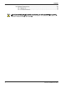
< Indoor Unit >
Stylish Flat Design
Higher Energy Saving
High Grade DC Inverter Model
-DC Compressor (Reluctance DC Motor)
-DC Fan Motor (both Indoor and Outdoor Unit)
< Outdoor Unit >
Quiet Sound Levels
Comfortable Functions
Easy Maintenance
Wipe-clean Flat Panel
Removable Drain Pan
Pair/Multi Compatible Indoor Unit
05RAG19A- 4
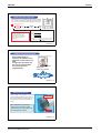
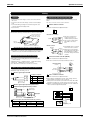
Stylish Flat Design
New Stylish Flat Design
harmonizes with interiors
and the simple design does
not make you feel the
existence of A/C in your
room.
Sophisticated edge
Simple display
Straight line
05RAG19A- 5
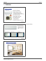
Installation Example
05RAG19A- 6
Room Air Conditioners E-Series
3
Features
ED04-805
Swing Compressor
Large Energy Savings
Smooth rotation with little friction and refrigerant gas
compression with little loss, allowing high operation
efficiency
Low Vibrations and Low Noise
Smooth piston motion as if sliding along a “groove,”
resulting in low vibrations and low noise
High Durability
Few parts rubbing each other during operation,
achieving high performance and reliability
Reluctance DC Motor
Higher efficiency with 2 different torques
– magnetic torque of ND magnet
and reluctance torque
Distinctive effect in energy-saving
running in low-frequency zone
Neodymium
magnet
Ferrite
magnet
05RAG19A- 11
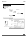
DC Fan Motor
DC motor efficiency
(comparison with a conventional AC motor)
80
Efficiency (%)
A DC fan motor is
introduced in this small class.
The motor features fine
rotation control and improved
energy consumption.
DC motor
Approx.
20%
60
increase
40 Approx.
AC motor
40%
20
increase
0
200
300
400
500
600
700
800
900 1000
Motor speed (rpm)
05RAG19A- 12
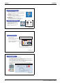
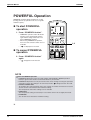
ECONO Mode
Decrease the Operating Current
The "ECONO mode" reduces the maximum operating current and power
consumption by approx. 30% during start up etc..
This mode is particularly convenient for energy-saving-oriented users. It
is also a major bonus for those whose breaking capacities do not allow the
use of multiple electrical devices and air conditioners.
It is easily activated from the wireless remote controller by pushing the
ECONO button.
Operation Image
05RAG19A- 17
4
Room Air Conditioners E-Series
ED04-805
Features
ECONO Mode
Notes
- When this function is ON, the maximum capacity is
also down. (Approx. 20%)
- In case of the multi system connection, the unit drops
maximum capacity to equal level with nominal
capacity in stead of current control.
- This function can only be set when the unit is running.
Pressing the operation stop button causes the
settings to be canceled.
- This function and "Powerful operation" cannot be
used at the same time. (Priority is given to Powerful
operation.)
05RAG19A- 18
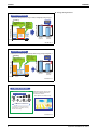
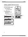
INTELLIGENT EYE
= Sensing human presence utilizing infrared rays =
Coverage Area
within 7 m (Max)
INTELLIGENT
EYE Sensor
110˚
Max.
7m
90˚
05RAG19A- 19
INTELLIGENT EYE
= Just one push of the [SENSOR] button =
ON
CANCEL
Sensor
OFF
TIMER
05RAG19A- 20
Room Air Conditioners E-Series
5
Features
ED04-805
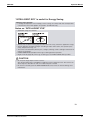
Energy Saving Functions
INTELLIGENT EYE
= Automatic shift up when sensing no human, intelligently saving energy =
Cooling
Temperature
Energy
Saving
operation
Absence 20min
Power consumption
Normal
operation
Saving
20%!
Back to
normal
operation
when
presence
detected
• 2˚C Shift up
• Minimum frequency
(34Hz)
Normal
operation
Normal
operation
time
Energy saving
operation
activated
05RAG19A- 21
INTELLIGENT EYE
= When absence shift down automatically makes energy saving intelligently =
Heating
Temperature
Energy
Saving
operation
Absence 20min
Power consumption
Normal
operation
Saving
30%!
Returns to
normal operation
upon sensing
a sign of human
• 2˚C Shift down
• Minimum frequency
(34Hz)
Normal
operation
Normal
operation
Energy saving
operation
activated
time
05RAG19A- 22
6 Steps Air Flow Rate
Air Flow Setting on the R/C
Indoor Unit Quiet Operation
Selectable 6 steps air flow rate
(5 steps and Quiet) make fine
on-demand comfort.
Quiet Operation for Better Sleep
SL
L ML M MH H
Decrease sound level
A sound level step by step decreases
approximately 2 or 3 dB by choosing
smaller airflow setting.
05RAG19A- 23
6
Room Air Conditioners E-Series
ED04-805
Features
Indoor Unit Quiet Operation
When air flow is set to “Quiet” through a remote controller,
the operation sound of the indoor unit is reduced by 3dB.
This is a convenient function while studying or sleeping.
Air flow setting button
Auto
Super
Low (SL)
Low
(L)
Middle
(M)
High
(H)
Indoor unit’s fan
<Note>
H
If the unit operates in “SL” or
“L” mode with small air flow,
operating noise is reduced but
cooling / heating capacity is
reduced too.
M
L
SL
Quiet “ON”
05RAG19A- 24
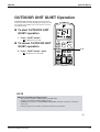
Outdoor Unit Quiet Operation
When QUIET button is
selected, the outdoor unit’s
operation sound reduces by
3dB.
In night time operation, the
unit can be operated with
less nuisance to the
neighborhood.
Outdoor Unit Quiet Operation button
Lowering the revolution
speed of the
compressor and fan.
3dB down
05RAG19A- 26
Mold Proof Function
After cooling or dry operation, some drain
water remains inside the indoor unit (on
the heat exchanger, the drain pan, etc...).
This moisture causes the generation of
mold.
The "Mold Proof Operation"
reduces the spread of mold,
and decreases nasty odors that
is caused by the mold.
Heat Exchanger
Drain Pan
05RAG19A- 28
Room Air Conditioners E-Series
7
Features
ED04-805
Mold Proof Function
Press and hold the "MOLD PROOF" button for 2
seconds in advance.
When the unit turned off after cooling or dry operation,
the unit starts fan
operation at a slow
speed* for
approximately 1 hour.
The fan operation
vaporizes the moisture
inside the unit.
Note) * : the fan rotation speed is slower than the
"Indoor Unit Quiet Operation".
05RAG19A- 29
Mold Proof Function
Notes
- This function is not designed to remove existing dust
or mold.
- This function is not available when the unit is turned
off using the off timer.
- During this function is operated,
the flaps open a little and
air
the air is blown upward slightly.
Fraps
05RAG19A- 30
Healthy and Clean
Titanium Apatite Photocatalytic
Air-Purifying Filter
It lasts for three years without replacement
if washed about once every six months.
Absorbs microscopic particles, decomposes odours and even deactivates
bacteria and viruses.
ABSORB
REMOVE
05RAG19A- 31
8
Room Air Conditioners E-Series
ED04-805
Features
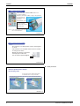
Wipe-clean Flat Panel
Grille Type :
Remove and wash the grille
Current models are …
New Flat Panel : Easy to clean without removing the panel
New models are …
Also washable after
removing the panel.
05RAG19A- 32
Room Air Conditioners E-Series
9
Power Supply
ED04-805
2. Power Supply
Note:
10
Indoor Units
Outdoor Units
FTKS25EVMA
RKS25EBVMA
FTKS35EVMA
RKS35EBVMA
FTXS25EVMA
RXS25EBVMA
FTXS35EVMA
RXS35EBVMA
Power Supply
1φ, 220-240V, 50Hz
1φ, 220-230V, 60Hz
Power Supply Intake ; Outdoor Unit
Room Air Conditioners E-Series
ED04-805
Functions
Compressor
Comfortable
Airflow
Comfort
Control
Operation
Lifestyle
Convenience
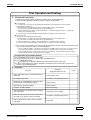
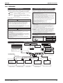
{
Operation Limit for Cooling (°CDB)
10
~46
Operation Limit for Heating (°CWB)
—
–10
~20
FTXS25/35EVMA
RXS25/35EBVMA
{
10
~46
Inverter (with Inverter Power Control)
FTKS25/35EVMA
RKS25/35EBVMA
Basic
Function
Functions
FTXS25/35EVMA
RXS25/35EBVMA
Category
FTKS25/35EVMA
RKS25/35EBVMA
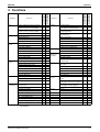
3. Functions
Air Purifying Filter
—
—
Photocatalytic Deodorizing Filter
—
—
Air Purifying Filter with Photocatalytic
Deodorizing Function
—
—
Category
Health &
Clean
Functions
PAM Control
{
{
Oval Scroll Compressor
—
—
Titanium Apatite Photocatalytic
Air-Purifying Filter
{
{
{
Swing Compressor
{
{
Mold Proof Air Filter
{
Rotary Compressor
—
—
Wipe-clean Flat Panel
{
{
Reluctance DC Motor
{
{
Washable Grille
—
—
Power-Airflow Flap
—
—
Mold Proof Operation
{
{
Power-Airflow Dual Flaps
{
{
Heating Dry Operation
—
—
Power-Airflow Diffuser
—
—
Wide-Angle Louvers
{
{
Vertical Auto-Swing (Up and Down)
{
{
Horizontal Auto-Swing (Right and Left)
—
—
3-D Airflow
—
—
Comfort Airflow Mode
—
Good-Sleep Cooling Operation
—
—
24-Hour On/Off Timer
{
{
Night Set Mode
{
{
Auto-Restart (after Power Failure)
{
{
Self-Diagnosis (Digital, LED) Display
{
{
—
Wiring Error Check
—
—
Anticorrosion Treatment of Outdoor
Heat Exchanger
{
{
{
{
Timer
Worry Free
“Reliability &
Durability”
3-Step Airflow (H/P Only)
—
—
Auto Fan Speed
{
{
Indoor Unit Quiet Operation
{
{
Night Quiet Mode (Automatic)
—
—
Multi-Split / Split Type Compatible
Indoor Unit
Outdoor Unit Quiet Operation (Manual)
{
{
Flexible Voltage Correspondence
{
{
INTELLIGENT EYE
{
{
High Ceiling Application
—
—
Quick Warming Function
—
{
Chargeless
10m
10m
Hot-Start Function
—
{
Either Side Drain (Right or Left)
{
{
Automatic Defrosting
—
{
Power Selection
—
—
Automatic Operation
—
{
Programme Dry Function
{
{
5-Rooms Centralized Controller
(Option)
{
{
Fan Only
{
{
Remote Control Adaptor
(Normal Open-Pulse Contact) (Option)
{
{
New POWERFUL Operation
(Non-Inverter)
—
—
Remote Control Adaptor
(Normal Open Contact) (Option)
{
{
{
Inverter POWERFUL Operation
{
{
Priority-Room Setting
—
—
Cooling / Heating Mode Lock
—
—
HOME LEAVE Operation
—
—
ECONO Mode
{
{
Indoor Unit On/Off Switch
{
{
Signal Reception Indicator
{
{
Temperature Display
—
—
Another Room Operation
—
—
Flexibility
Remote
Control
Remote
Controller
DIII-NET Compatible (Adaptor) (Option)
{
Wireless
{
{
Wired
—
—
Note: { : Holding Functions
— : No Functions
Room Air Conditioners E-Series
11
Specifications
ED04-805
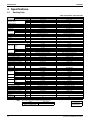
4. Specifications
4.1
Cooling Only
50Hz 220-230-240V / 60Hz 220-230V
Models
Indoor Units
Outdoor Units
Capacity
Rated (Min.~Max.)
Moisture Removal
Running Current (Rated)
Power Consumption (Rated)
Power Factor
COP (Rated)
Liquid
Piping
Connections Gas
Drain
Heat Insulation
Max. Interunit Piping Length
Max. Interunit Height Difference
Chargeless
Amount of Additional Charge
of Refrigerant
Indoor Units
Front Panel Color
Air Flow Rate m³/min
(cfm)
Type
Motor Output
Speed
Air Direction Control
Air Filter
Running Current (Rated)
Power Consumption (Rated)
Power Factor
Temperature Control
Dimensions (H×W×D)
Packaged Dimensions (H×W×D)
Weight
Gross Weight
Operation
H/M/L/SL
Sound
Outdoor Units
Casing Color
Type
Compressor Model
Motor Output
Type
Refrigerant
Oil
Charge
Type
Refrigerant
Charge
Air Flow Rate m³/min
(cfm)
Type
Fan
Motor Output
Running Current (Rated)
Power Consumption (Rated)
Power Factor
Starting Current
Dimensions (H×W×D)
Packaged Dimensions (H×W×D)
Weight
Gross Weight
Operation
H/L
Sound
Sound Power (H)
Drawing No.
Fan
Note:
FTKS25EVMA
RKS25EBVMA
2.5 (1.2~3.0)
8,500 (4,100~10,200)
2,150 (1,030~2,580)
1.2
3.5-3.3-3.2 / 3.5-3.3
600 (300~800)
77.9-79.1-78.1 / 77.9-79.1
4.17 (4.00~3.75)
φ 6.4
φ 9.5
φ18.0
Both Liquid and Gas Pipes
20
15
10
kW
Btu/h
kcal/h
L/h
A
W
%
W/W
mm
mm
mm
m
m
m
g/m
H
M
L
SL
W
Steps
A
W
%
mm
mm
kg
kg
20
20
FTKS25EVMA
White
8.7 (307)
6.7 (237)
4.7 (166)
3.9 (138)
Cross Flow Fan
40
5 Steps, Quiet, Auto
Right, Left, Horizontal, Downward
Removable / Washable / Mildew Proof
0.17-0.16-0.15 / 0.17-0.16
35-35-35 / 35-35
93.6-95.1-97.2 / 93.6-95.1
Microcomputer Control
283×800×195
265×855×340
9
12
FTKS35EVMA
White
8.9 (314)
6.9 (244)
4.8 (169)
4.0 (141)
Cross Flow Fan
40
5 Steps, Quiet, Auto
Right, Left, Horizontal, Downward
Removable / Washable / Mildew Proof
0.19-0.18-0.17 / 0.19-0.18
40-40-40 / 40-40
95.7-96.6-98.0 / 95.7-96.6
Microcomputer Control
283×800×195
265×855×340
9
12
dBA
37/31/25/22
38/32/26/23
W
A
W
%
A
mm
mm
kg
kg
RKS25EBVMA
Ivory White
Hermetically Sealed Swing Type
1YC23NXD
600
FVC50K
0.375
R-410A
1.0
33.5 (1,183)
23.4 (826)
Propeller
50
3.33-3.14-3.05 / 3.33-3.14
565-565-565 / 565-565
77.1-78.2-77.2 / 77.1-78.2
3.5
550×765×285
589×882×363
34
40
RKS35EBVMA
Ivory White
Hermetically Sealed Swing Type
1YC23NXD
600
FVC50K
0.375
R-410A
1.0
33.5 (1,183)
23.4 (826)
Propeller
50
4.71-4.52-4.33 / 4.71-4.52
980-980-980 / 980-980
94.6-94.3-94.3 / 94.6-94.3
4.9
550×765×285
589×882×363
34
40
dBA
46/43
47/44
dBA
61
3D058977
62
3D058978
W
L
kg
H
L
The data are based on the conditions shown in the table below.
Cooling
Indoor ; 27°CDB/19°CWB
Outdoor ; 35°CDB/24°CWB
12
FTKS35EVMA
RKS35EBVMA
3.5 (1.2~3.8)
11,900 (4,100~12,950)
3,010 (1,030~3,260)
1.9
4.9-4.7-4.5 / 4.9-4.7
1,020 (300~1,200)
94.6-94.4-94.4 / 94.6-94.4
3.43 (4.00~3.17)
φ 6.4
φ 9.5
φ18.0
Both Liquid and Gas Pipes
20
15
10
Piping Length
Conversion Formulae
7.5m
kcal/h=kW×860
Btu/h=kW×3414
cfm=m³/min×35.3
Room Air Conditioners E-Series
ED04-805
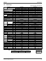
4.2
Specifications
Heat Pump
50Hz 220-230-240V / 60Hz 220-230V
Indoor Units
Models
FTXS25EVMA
RXS25EBVMA
Outdoor Units
Capacity
Rated (Min.~Max.)
Moisture Removal
Running Current (Rated)
Power Consumption (Rated)
Power Factor
COP (Rated)
Liquid
Piping
Connections Gas
Drain
Heat Insulation
Max. Interunit Piping Length
Max. Interunit Height Difference
Chargeless
Amount of Additional Charge
of Refrigerant
Indoor Units
Front Panel Color
kW
Btu/h
kcal/h
L/h
A
W
%
W/W
mm
mm
mm
Type
Motor Output
Speed
Air Direction Control
Air Filter
Running Current (Rated)
Power Consumption (Rated)
Power Factor
Temperature Control
Dimensions (H×W×D)
Packaged Dimensions (H×W×D)
Weight
Gross Weight
Operation
H/M/L/SL
Sound
Outdoor Units
Casing Color
Type
Compressor Model
Motor Output
Type
Refrigerant
Oil
Charge
Type
Refrigerant
Charge
Fan
H
M
L
SL
W
Steps
A
W
%
mm
mm
kg
kg
dBA
W
L
kg
H
L
Fan
Note:
Heating
3.4 (1.2~4.5)
11,600 (4,100~15,350)
2,920 (1,030~3,870)
—
4.3-4.1-3.9 / 4.3-4.1
830 (290~1,340)
87.7-88.0-88.7 / 87.7-88.0
4.10 (4.14~3.36)
φ 6.4
φ 9.5
φ18.0
Both Liquid and Gas Pipes
20
15
10
g/m
Air Flow Rate m³/min (cfm)
Type
Motor Output
Running Current (Rated)
Power Consumption (Rated)
Power Factor
Starting Current
Dimensions (H×W×D)
Packaged Dimensions (H×W×D)
Weight
Gross Weight
Operation
H/L
Sound
Sound Power (H)
Drawing No.
Cooling
2.5 (1.2~3.0)
8,500 (4,100~10,200)
2,150 (1,030~2,580)
1.2
3.5-3.3-3.2 / 3.5-3.3
600 (300~800)
77.9-79.1-78.1 / 77.9-79.1
4.17 (4.00~3.75)
m
m
m
Air Flow Rate m³/min
(cfm)
W
A
W
%
A
mm
mm
kg
kg
FTXS35EVMA
RXS35EBVMA
Cooling
3.5 (1.2~3.8)
11,900 (4,100~12,950)
3,010 (1,030~3,260)
1.9
4.9-4.7-4.5 / 4.9-4.7
1,020 (300~1,200)
94.6-94.4-94.4 / 94.6-94.4
3.43 (4.00~3.17)
Heating
4.0 (1.2~5.0)
13,600 (4,100~17,050)
3,440 (1,030~4,300)
—
5.1-4.9-4.7 / 5.1-4.9
1,080 (290~1,550)
96.3-95.8-95.7 / 96.3-95.8
3.70 (4.14~3.23)
φ 6.4
φ 9.5
φ18.0
Both Liquid and Gas Pipes
20
15
10
20
20
FTXS25EVMA
White
FTXS35EVMA
White
8.7 (307)
6.7 (237)
4.7 (166)
3.9 (138)
9.4 (332)
7.6 (268)
5.8 (205)
5.0 (177)
8.9 (314)
6.9 (242)
4.8 (169)
4.0 (141)
Cross Flow Fan
40
5 Steps, Quiet, Auto
Right, Left, Horizontal, Downward
Removable / Washable / Mildew Proof
0.17-0.16-0.15 / 0.17-0.16
0.17-0.16-0.15 / 0.17-0.16
35-35-35 / 35-35
35-35-35 / 35-35
93.6-95.1-97.2 / 93.6-95.1
93.6-95.1-97.2 / 93.6-95.1
Microcomputer Control
283×800×195
265×855×340
9
12
37/31/25/22
Cross Flow Fan
40
5 Steps, Quiet, Auto
Right, Left, Horizontal, Downward
Removable / Washable / Mildew Proof
0.19-0.18-0.17 / 0.19-0.18
0.19-0.18-0.17 / 0.19-0.18
40-40-40 / 40-40
40-40-40 / 40-40
95.7-96.6-98.0 / 95.7-96.6
95.7-96.6-98.0 / 95.7-96.6
Microcomputer Control
283×800×195
265×855×340
9
12
37/33/28/25
38/32/26/23
RXS25EBVMA
Ivory White
Hermetically Sealed Swing Type
1YC23NXD
600
FVC50K
0.375
R-410A
1.0
33.5 (1,183)
30.2 (1,066)
23.4 (826)
28.3 (999)
Propeller
50
3.33-3.14-3.05 / 3.33-3.14
4.13-3.94-3.75 / 4.13-3.94
565-565-565 / 565-565
795-795-795 / 795-795
77.1-78.2-77.2 / 77.1-78.2
87.5-87.7-88.3 / 87.5-87.7
4.3
550×765×285
589×882×363
34
40
dBA
46/43
47/44
47/44
—
62
—
3D058979
Room Air Conditioners E-Series
48/45
63
3D058980
The data are based on the conditions shown in the table below.
Heating
Indoor ; 20°CDB
Outdoor ; 7°CDB/6°CWB
38/34/29/26
RXS35EBVMA
Ivory White
Hermetically Sealed Swing Type
1YC23NXD
600
FVC50K
0.375
R-410A
1.0
33.5 (1,183)
30.2 (1,066)
23.4 (826)
28.3 (999)
Propeller
50
4.71-4.52-4.33 / 4.71-4.52
4.91-4.72-4.53 / 4.91-4.72
980-980-980 / 980-980
1,040-1,040-1,040 / 1,040-1,040
94.6-94.3-94.3 / 94.6-94.3
96.3-95.8-95.7 / 96.3-95.8
5.1
550×765×285
589×882×363
34
40
dBA
Cooling
Indoor ; 27°CDB/19°CWB
Outdoor ; 35°CDB/24°CWB
9.7 (342)
7.9 (277)
6.0 (212)
5.2 (184)
Piping Length
Conversion Formulae
7.5m
kcal/h=kW×860
Btu/h=kW×3414
cfm=m³/min×35.3
13
Dimensions
ED04-805
5. Dimensions
5.1
Indoor Units
THE MARK (→) SHOWS PIPING DIRECTION
AIR FLOW(INDOOR )
30MIN.
REAR
800
RIGHT
LEFT
( INCLUDING
MOUNTING PLATE )
197
50MIN.
50MIN.
(SPACEFOR
MAINTENANCE)
195
( SPACE FOR
PERFORMANCE)
FTKS25/35EVMA
(SPACE FOR
MAINTENANCE)
REQUIRED SPACE
SIGNAL RECEIVER
TIMER LAMP
INTELLIGENT EYE LAMP
283
NAME PLATE
OPERATION LAMP
TERMINAL BLOCK
WITH EARTH
TERMINAL
INTELLIGENT EYE SENSOR
BOTTOM
GAS PIPE 9.5Cut
(THE LENGTH OF PIPE OUTSIDE
THE UNIT:ABOUT390)
DRAIN HOSE
(CONNECTING PART
I. D. φ14
LIQUID PIPE 6.4CuT
O. D.φ18
(THE LENGTH OF PIPE OUTSIDE THE HOSE LENGTH OF OUTSIDE
THE UNIT:ABOUT 340)
THE UNIT IS APPROX. 440)
INDOOR UNIT ON/OFF SWITCH
FRONT PANEL FIXED SCREWS
FLAPS
( INSIDE )
ROOM TEMP. THERMISTOR( INSIDE )
SIGNAL TRANSMITTER
49
711
17
BLADE ANGLE
18
13
800
58
UP/DOWN( AUTOMATIC )
163
110
60
50°
WALL HOLE FOR EMBEDDED PIPING
φ65 HOLE
70°
STANDARD LOCATIONS OF WALL HOLES
RIGHT/LEFT( MANUAL )
44.5
5°
10°
WIRELESS REMOTE CONTROLLER
283
44.5
FAN
COOLING, DRY
180
DAIKIN
WALL HOLE
φ65 HOLE
( ARC433B47 )
3D047958E
45°
45°
THE MARK (→) SHOWS PIPING DIRECTION
AIR FLOW( INDOOR )
30MIN.
REAR
800
RIGHT
LEFT
( INCLUDING
MOUNTING PLATE )
197
50MIN.
50MIN.
( SPACE FOR
MAINTENANCE )
195
( SPACE FOR
PERFORMANCE )
FTXS25/35EVMA
( SPACE FOR
MAINTENANCE )
REQUIRED SPACE
SIGNAL RECEIVER
283
NAME PLATE
OPERATION LAMP
TIMER LAMP
INTELLIGENT EYE LAMP
TERMINAL BLOCK
WITH EARTH
TERMINAL
INTELLIGENT EYE SENSOR
BOTTOM
GAS PIPE 9.5Cut
( THE LENGTH OF PIPE OUTSIDE
THEUNIT:ABOUT390 )
DRAIN HOSE
( CONNECTING PART
I. D.φ14
LIQUID PIPE 6.4CuT
O. D.φ18
( THE LENGTH OF PIPE OUTSIDE THE HOSE LENGTH OF OUTSIDE
THE UNIT:ABOUT 340 )
THE UNIT IS APPROX. 440 )
INDOOR UNIT ON/OFF SWITCH
FRONT PANEL FIXED SCREWS
FLAPS
( INSIDE )
ROOM TEMP. THERMISTOR( INSIDE )
SIGNAL TRANSMITTER
49
711
17
BLADE ANGLE
18
13
800
58
UP/DOWN( AUTOMATIC )
163
FAN
110
60
30°
50°
65°
RIGHT/LEFT( MANUAL )
70°
WALL HOLE FOR EMBEDDED PIPING
φ65 HOLE
STANDARD LOCATIONS OF WALL HOLES
44.5
5°
10°
WIRELESS REMOTE CONTROLLER
283
HEATING
44.5
COOLING, DRY
180
DAIKIN
WALL HOLE
φ65 HOLE
( ARC433B46 )
45°
14
45°
3D047956D
Room Air Conditioners E-Series
ED04-805
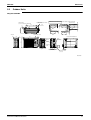
5.2
Dimensions
Outdoor Units
4 - HOLES FOR ANCHOR BOLTS
(M8 OR M10)
DRAIN OUTLET
(I.D φ15.9 HOSE FOR CONNECTION)
574
MINIMUM SPACE FOR AIR PASSAGE
105.5
50
50
100
50
50
300
150
100
13
490
29.5
311
WALL HEIGHT ON AIR OUTLET SIDE
=LESS THAN 1200
150
RK(X)S25/35EBVMA
HANDLE
BRAND NAME LABEL
12
765
63
OUTDOOR AIR THERMISTOR
MANUFACTURE'S
LABEL
LIQUID
STOP VALVE
(φ6.4CuT)
550
WIRING
INLET
SERVICE
PORT
INDICATION LABEL
196
IN CASE OF REMOVING
STOP VALVE COVER
165
8
105
285
22
GAS STOP VALVE
(φ9.5CuT)
3D059795
Room Air Conditioners E-Series
15
Wiring Diagrams
ED04-805
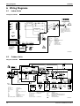
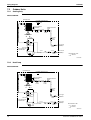
6. Wiring Diagrams
6.1
Indoor Units
FTK(X)S25/35EVMA
FIELD WIRING.
S27
PCB3
S26
PCB1
~
F1U
~
RECTIFIER
LED1
H1
1
3.15A
X1M
V1
H1P
H2
LED2
H2P
LED3
H3P
1
WHT
2
RED
3
GRN /
H3
TRANSMISSION
CIRCUIT
BLK
2
3
CAUTION
NOTE THAT OPERATION WILL
RESTART AUTOMATICALLY IF
THE MAIN POWER SUPPLY IS
TURNED OFF AND THEN BACK
ON AGAIN.
YLW
FG
S1W
7
S21
S1
RED
t°
HA
R1T
WHT
1
S35
INTELLIGENT EYE
SENSOR
S28
S32
PCB2
1
S6
M
M1F
5
:
:
:
:
:
:
:
:
:
:
:
RED
ORG
YLW
PNK
BLU
S36
FG
F1U
H1P~H3P
M1F
M1S
PCB1~PCB4
R1T, R2T
S1~S38
S1W
X1M
BLU
BRN
ORG
PCB4
t°
OUTDOOR
FRAME GROUND
FUSE
PILOT LAMP
FAN MOTOR
SWING MOTOR
PRINTED CIRCUIT BOARD
THERMISTOR.
CONNECTOR
OPERATION SWITCH
TERMINAL STRIP
PROTECTIVE EARTH
S29
R2T
WIRELESS
REMOTE
CONTROLLER
SIGNAL
RECEIVER
INDOOR
M
M1S
3D046453B
6.2
Outdoor Units
RK(X)S25/35EBVMA
R12T
t°
BRN
L1
BLK
HR1
V2
HN2
S
RED
GRN/YLW
GRN/YLW
7
HC3
+
GRY
HN3
BLU
1
DB2
~ +
~ _
C74
+
_
C94
+
_
FU2
3.15A
~ _
FU1
IC11
C75
3.15A
+
_
+
_ C95
7
PCB2
MRCW
S20
6
1
1
3
S90
S70
6
1 2 34
1
16
: CAPACITOR
: DIODE BRIDGE
: FUSE
: TRIAC
: INTELLIGENT POWER MODULE
: LIVE
: COIL
: REACTOR
: COMPRESSOR MOTOR
: FAN MOTOR
: MAGNETIC RELAY
WHT
ORG
BRN
BLU
RED
BLK
BLK
BLK
BLK
BLK
BLK
S30
5
1
3
1
3
S80
C74, C75
C94, C95, C100
DB1, DB2
FU1, FU2, FU3
IC11
IPM1
L
L1
L1R
M1C
M1F
MRCW, MRM10, MRM20
2
WHT
YLW
ORG
BLU
BRN
RED
outdoor
S40
7
S80
NOTE
1. REFER TO THE NAMEPLATE FOR THE POWER REQUIREMENTS.
_
W V U
V1
S10
1
IPM1
HC4
HR2 DB1
~ +
HL3
WHT
BLK
BLK
BLK
BLK
BLK
BLK
1
V3
E
ORG
ORG
S11
SA1
L
N
HL2
MRM10
HN1
WHT
L1R
RED
L 1
N 2
3
MRM20
BLU
1
2
3
PCB1
YLW
FU3
Z2C HL1 20A
X1M
YLW
HC1
GRY
HC2
BLK
FIELD WIRING.
BLK
BLK
C100
indoor
IN CASE OF
COOLING ONLY
TYPE
N
PCB1, PCB2
Q1L
R1T, R2T, R3T, R12T
S10, S11, S20
S30, S40, S70
S80, S90, S91
HC3, HC4, HL3, HN3
t°
Y1R
M
Y1E
IN CASE OF
HEAT PUMP
TYPE
: NEUTRAL
: PRINTED CIRCUIT BOARD
: OVERLOAD PROTECTOR
: THERMISTOR
: CONNECTOR
t°
t°
M
V
1~
R1T R2T R3T
(OUTDOOR)
(DISCHARGE)
(CONDENSER)
SA1
V1, V2, V3
X1M
Y1E
Y1R
Z1C, Z2C
M1F
Q1L
: SURGE ARRESTER
: VARISTOR
: TERMINAL STRIP
: ELECTRONIC EXPANSION VALVE COIL
: REVERSING SOLENOIDE VALVE COIL
: FERRITE CORE
: PROTECTIVE EARTH
W
Z1C
N=2
U
M1C
3D046707L
Room Air Conditioners E-Series
ED04-805
Piping Diagrams
7. Piping Diagrams
7.1
Indoor Units
FTXS25/35EVMA
FTKS25/35EVMA
INDOOR UNIT
INDOOR UNIT
MAFFLER ASSY
HEAT EXCHANGER
7.0CuT
MAFFLER ASSY
HEAT EXCHANGER
7.0CuT
FIELD PIPING
(6.4CuT)
6.4CuT
THERMISTOR
ON HEAT EXCH.
6.4CuT
7.9CuT
7.9CuT
6.4CuT
6.4CuT
CROSS FLOW FAN
FIELD PIPING
(6.4CuT)
M
FAN MOTOR
FIELD PIPING
(9.5CuT)
6.4CuT
6.4CuT
CROSS FLOW FAN
M
FAN MOTOR
9.5CuT
FIELD PIPING
(9.5CuT)
REFRIGERANT FLOW
COOLING
4D050757B
Room Air Conditioners E-Series
THERMISTOR
ON HEAT EXCH.
9.5CuT
REFRIGERANT FLOW
COOLING
HEATING
4D047912J
17
Piping Diagrams
ED04-805
7.2
Outdoor Units
7.2.1
Cooling Only
RKS25/35EBVMA
OUTDOOR UNIT
OUTDOOR TEMPERATURE
THERMISTOR
9.5CuT
7.0CuT HEAT EXCHANGER
7.0CuT
HEAT EXCHANGER
THERMISTOR
4.8CuT
6.4CuT 6.4CuT
MUFFLER
WITH
FILTER
9.5CuT
PROPELLER FAN
φ. 4.0×ID. 2.0CuT
4.8CuT MUFFLER
WITH
FILTER
M
MOTOR OPERATED
VALVE
9.5CuT
FOUR WAY
VALVE
NORMALLY : OFF
9.5CuT
7.9CuT
6.4CuT
MUFFLER
WITH
FILTER
LIQUID STOP
VALVE
7.9CuT
MUFFLER
DISCHARGE PIPE
THERMISTOR
9.5CuT
9.5CuT
COMPRESSOR
GAS STOP
VALVE
MUFFLER
ACCUMULATOR
FIELD PIPING
(6.4CuT)
FIELD PIPING
(9.5CuT)
REFRIGERANT FLOW
COOLING
3D047318F
7.2.2
Heat Pump
RXS25/35EBVMA
OUTDOOR UNIT
OUTDOOR TEMPERATURE
THERMISTOR
9.5CuT
7.0CuT HEAT EXCHANGER
7.0CuT
4.8CuT MUFFLER
WITH
FILTER
M
MUFFLER
WITH
FILTER
PROPELLER FAN
9.5CuT
MOTOR OPERATED
VALVE
9.5CuT
φ. 4.0×ID. 2.0CuT
HEAT EXCHANGER
THERMISTOR
4.8CuT
6.4CuT 6.4CuT
FOUR WAY
VALVE
ON : HEATING
9.5CuT
7.9CuT
6.4CuT
MUFFLER
WITH
FILTER
LIQUID STOP
VALVE
MUFFLER
FIELD PIPING
(6.4CuT)
7.9CuT
DISCHARGE PIPE
THERMISTOR
9.5CuT
COMPRESSOR
ACCUMULATOR
9.5CuT
MUFFLER
GAS STOP
VALVE
FIELD PIPING
(9.5CuT)
REFRIGERANT FLOW
COOLING
HEATING
3D047316J
18
Room Air Conditioners E-Series
ED04-805
Capacity Tables
8. Capacity Tables
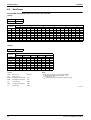
8.1
Cooling Only
FTKS25EVMA + RKS25EBVMA (50Hz 220-230-240V / 60Hz 220-230V)
AFR
8.7
BF
0.24
OUTDOOR TEMPERATURE(°CDB)
INDOOR
20
25
30
32
35
40
EWB
EDB
TC
SHC
PI
TC
SHC
PI
TC
SHC
PI
TC
SHC
PI
TC
SHC
PI
TC
SHC
PI
°C
°C
kW
kW
kW
kW
kW
kW
kW
kW
kW
kW
kW
kW
kW
kW
kW
kW
kW
kW
14.0
20
2.56
1.93
0.46
2.44
1.87
0.50
2.33
1.82
0.55
2.28
1.79
0.57
2.21
1.76
0.59
2.10
1.70
0.64
16.0
22
2.68
1.90
0.46
2.56
1.84
0.51
2.44
1.79
0.55
2.40
1.77
0.57
2.33
1.74
0.60
2.21
1.69
0.64
18.0
25
2.79
1.99
0.47
2.68
1.94
0.51
2.56
1.89
0.55
2.51
1.87
0.57
2.44
1.84
0.60
2.33
1.80
0.64
19.0
27
2.85
2.11
0.47
2.73
2.06
0.51
2.62
2.01
0.56
2.57
1.99
0.57
2.50
1.96
0.60
2.38
1.92
0.64
22.0
30
3.02
2.03
0.47
2.91
1.99
0.52
2.79
1.95
0.56
2.74
1.93
0.58
2.67
1.91
0.60
2.56
1.86
0.65
24.0
32
3.14
1.98
0.47
3.02
1.94
0.52
2.90
1.90
0.56
2.86
1.89
0.58
2.79
1.86
0.61
2.67
1.83
0.65
Symbols
NOTE:
AFR
: Air flow rate
(m³/min.)
BF
: Bypass factor
EWB
: Entering wet bulb temp.
(°C)
EDB
: Entering dry bulb temp.
(°C)
TC
: Total capacity
(kW)
SHC
: Sensible heat capacity
(kW)
PI
: Power input
(kW)
1. Capacities are based on the following conditions.
Corresponding refrigerant piping length : 7.5m
Level difference : 0m
2.
shows nominal (rated) capacities and power input.
3D054239A
FTKS35EVMA + RKS35EBVMA (50Hz 220-230-240V / 60Hz 220-230V)
AFR
8.9
BF
0.24
OUTDOOR TEMPERATURE(°CDB)
INDOOR
20
25
30
32
35
40
EWB
EDB
TC
SHC
PI
TC
SHC
PI
TC
SHC
PI
TC
SHC
PI
TC
SHC
PI
TC
SHC
PI
°C
°C
kW
kW
kW
kW
kW
kW
kW
kW
kW
kW
kW
kW
kW
kW
kW
kW
kW
kW
14.0
20
3.31
2.33
0.78
3.31
2.33
0.86
3.26
2.31
0.93
3.19
2.27
0.96
3.10
2.22
1.01
2.93
2.13
1.08
16.0
22
3.75
2.44
0.79
3.58
2.35
0.86
3.42
2.27
0.94
3.36
2.24
0.97
3.26
2.19
1.01
3.10
2.11
1.09
18.0
25
3.91
2.52
0.79
3.75
2.44
0.87
3.58
2.37
0.94
3.52
2.34
0.97
3.42
2.29
1.02
3.26
2.22
1.09
19.0
27
3.99
2.63
0.79
3.83
2.55
0.87
3.66
2.48
0.94
3.60
2.45
0.97
3.50
2.41
1.02
3.34
2.33
1.10
22.0
30
4.23
2.53
0.80
4.07
2.46
0.88
3.90
2.39
0.95
3.84
2.37
0.98
3.74
2.33
1.03
3.58
2.26
1.10
24.0
32
4.39
2.45
0.81
4.23
2.39
0.88
4.07
2.33
0.96
4.00
2.30
0.99
3.90
2.27
1.03
3.74
2.21
1.11
Symbols
AFR
: Air flow rate
BF
: Bypass factor
NOTE:
(m³/min.)
EWB
: Entering wet bulb temp.
(°C)
EDB
: Entering dry bulb temp.
(°C)
TC
: Total capacity
(kW)
SHC
: Sensible heat capacity
(kW)
PI
: Power input
(kW)
1. Capacities are based on the following conditions.
Corresponding refrigerant piping length : 7.5m
Level difference : 0m
2.
shows nominal (rated) capacities and power input.
3D054240A
Room Air Conditioners E-Series
19
Capacity Tables
8.2
ED04-805
Heat Pump
FTXS25EVMA+ RXS25EBVMA (50Hz 220-230-240V / 60Hz 220-230V)
Cooling
AFR
8.7
BF
0.24
OUTDOOR TEMPERATURE(°CDB)
INDOOR
20
25
30
32
35
40
EWB
EDB
TC
SHC
PI
TC
SHC
PI
TC
SHC
PI
TC
SHC
PI
TC
SHC
PI
TC
SHC
PI
°C
°C
kW
kW
kW
kW
kW
kW
kW
kW
kW
kW
kW
kW
kW
kW
kW
kW
kW
kW
14.0
20
2.56
1.93
0.46
2.44
1.87
0.50
2.33
1.82
0.55
2.28
1.79
0.57
2.21
1.76
0.59
2.10
1.70
0.64
16.0
22
2.68
1.90
0.46
2.56
1.84
0.51
2.44
1.79
0.55
2.40
1.77
0.57
2.33
1.74
0.60
2.21
1.69
0.64
18.0
25
2.79
1.99
0.47
2.68
1.94
0.51
2.56
1.89
0.55
2.51
1.87
0.57
2.44
1.84
0.60
2.33
1.80
0.64
19.0
27
2.85
2.11
0.47
2.73
2.06
0.51
2.62
2.01
0.56
2.57
1.99
0.57
2.50
1.96
0.60
2.38
1.92
0.64
22.0
30
3.02
2.03
0.47
2.91
1.99
0.52
2.79
1.95
0.56
2.74
1.93
0.58
2.67
1.91
0.60
2.56
1.86
0.65
24.0
32
3.14
1.98
0.47
3.02
1.94
0.52
2.90
1.90
0.56
2.86
1.89
0.58
2.79
1.86
0.61
2.67
1.83
0.65
Heating
AFR
9.4
OUTDOOR TEMPERATURE(°CWB)
INDOOR
–10
–5
0
6
10
EDB
TC
PI
TC
PI
TC
PI
TC
PI
TC
PI
°C
kW
kW
kW
kW
kW
kW
kW
kW
kW
kW
15.0
2.29
0.70
2.67
0.74
3.06
0.77
3.52
0.81
3.82
0.84
20.0
2.17
0.72
2.56
0.75
2.94
0.79
3.40
0.83
3.71
0.86
22.0
2.12
0.73
2.51
0.76
2.89
0.80
3.35
0.84
3.66
0.86
24.0
2.08
0.74
2.46
0.77
2.85
0.80
3.31
0.84
3.61
0.87
25.0
2.05
0.74
2.44
0.77
2.82
0.81
3.28
0.85
3.59
0.88
27.0
2.01
0.75
2.39
0.78
2.77
0.82
3.24
0.86
3.54
0.88
Symbols
AFR
: Air flow rate
BF
: Bypass factor
NOTE:
(m³/min.)
EWB
: Entering wet bulb temp.
(°C)
EDB
: Entering dry bulb temp.
(°C)
TC
: Total capacity
(kW)
SHC
: Sensible heat capacity
(kW)
PI
: Power input
(kW)
1. Capacities are based on the following conditions.
Corresponding refrigerant piping length : 7.5m
Level difference : 0m
2.
shows nominal (rated) capacities and power input.
3D054237A
20
Room Air Conditioners E-Series
ED04-805
Capacity Tables
FTXS35EVMA + RXS35EBVMA (50Hz 220-230-240V / 60Hz 220-230V)
Cooling
AFR
8.9
BF
0.24
OUTDOOR TEMPERATURE(°CDB)
INDOOR
20
25
30
32
35
40
EWB
EDB
TC
SHC
PI
TC
SHC
PI
TC
SHC
PI
TC
SHC
PI
TC
SHC
PI
TC
SHC
PI
°C
°C
kW
kW
kW
kW
kW
kW
kW
kW
kW
kW
kW
kW
kW
kW
kW
kW
kW
kW
14.0
20
3.31
2.33
0.78
3.31
2.33
0.86
3.26
2.31
0.93
3.19
2.27
0.96
3.10
2.22
1.01
2.93
2.13
1.08
16.0
22
3.75
2.44
0.79
3.58
2.35
0.86
3.42
2.27
0.94
3.36
2.24
0.97
3.26
2.19
1.01
3.10
2.11
1.09
18.0
25
3.91
2.52
0.79
3.75
2.44
0.87
3.58
2.37
0.94
3.52
2.34
0.97
3.42
2.29
1.02
3.26
2.22
1.09
19.0
27
3.99
2.63
0.79
3.83
2.55
0.87
3.66
2.48
0.94
3.60
2.45
0.97
3.50
2.41
1.02
3.34
2.33
1.10
22.0
30
4.23
2.53
0.80
4.07
2.46
0.88
3.90
2.39
0.95
3.84
2.37
0.98
3.74
2.33
1.03
3.58
2.26
1.10
24.0
32
4.39
2.45
0.81
4.23
2.39
0.88
4.07
2.33
0.96
4.00
2.30
0.99
3.90
2.27
1.03
3.74
2.21
1.11
Heating
AFR
9.7
OUTDOOR TEMPERATURE(°CWB)
INDOOR
–10
–5
0
6
10
EDB
TC
PI
TC
PI
TC
PI
TC
PI
TC
PI
°C
kW
kW
kW
kW
kW
kW
kW
kW
kW
kW
15.0
2.69
0.91
3.14
0.96
3.60
1.00
4.14
1.06
4.50
1.09
20.0
2.55
0.94
3.01
0.98
3.46
1.03
4.00
1.08
4.36
1.12
22.0
2.50
0.95
2.95
0.99
3.40
1.04
3.94
1.09
4.31
1.13
24.0
2.44
0.96
2.90
1.00
3.35
1.05
3.89
1.10
4.25
1.14
25.0
2.42
0.96
2.87
1.01
3.32
1.05
3.86
1.10
4.22
1.14
27.0
2.36
0.97
2.81
1.02
3.26
1.06
3.81
1.11
4.17
1.15
Symbols
NOTE:
AFR
: Air flow rate
(m³/min.)
BF
: Bypass factor
EWB
: Entering wet bulb temp.
(°C)
EDB
: Entering dry bulb temp.
(°C)
TC
: Total capacity
(kW)
SHC
: Sensible heat capacity
(kW)
PI
: Power input
(kW)
1. Capacities are based on the following conditions.
Corresponding refrigerant piping length : 7.5m
Level difference : 0m
2.
shows nominal (rated) capacities and power input.
3D054238A
Room Air Conditioners E-Series
21
Capacity Tables
8.3
ED04-805
Capacity correction factor by the length of refrigerant piping (Reference)
The cooling and the heating capacity of the unit has to be corrected in accordance with the length of
refrigerant piping. (The distance between the indoor unit and the outdoor unit)
<— line : cooling capacity>
<--- line : heating capacity>
R-410A (25/35 class)
Capacity correction factor
1
0.9
Range of the refrigerant
additional charge
0.8
5
10
15
20
Piping length (m)
(R4979)
Note:
22
The graph shows the factor when additional refrigerant of the proper quantity is charged.
Room Air Conditioners E-Series
ED04-805
Operation Limit
9. Operation Limit
9.1
Cooling Only
RKS25/35EBVMA
50
40
30
20
Pull-down period
Continuous operation
Outdoor temp.( °CDB)
46
10
10
14
20 23
Indoor temp.( °CWB)
Notes:
The graph is based
on the following conditions.
• Equivalent piping length
• Level difference
• Air flow rate
28 30
7.5m
0m
High
4D050467G
9.2
Heat Pump
RXS25/35EBVMA
Heating
Cooling
20
15
50
20
10
5
0
Continuous operation
Outdoor temp.(°CWB)
30
Pull-down period
40
Continuous operation
Outdoor temp.(°CDB)
46
-5
10
-10
(-10°CDB)
10
14
20 23
Indoor temp.(°CWB)
28 30
Notes:
The graphs are based
on the following conditions.
• Equivalent piping length
• Level difference
• Air flow rate
Room Air Conditioners E-Series
10
20
Indoor temp.(°CDB)
7.5m
0m
High
30
3D050466E
23
Sound Level
ED04-805
10. Sound Level
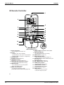
10.1 Measuring Location
Indoor Unit
Outdoor Unit
1m
0.8m
1m
(R4287)
(R4286)
Note:
1. Operation sound is measured in an anechoic chamber.
2. The data are based on the conditions shown in the table below.
Cooling
Indoor ; 27°CDB/19°CWB
Outdoor ; 35°CDB/24°CWB
24
Heating
Indoor ; 20°CDB
Outdoor ; 7°CDB/6°CWB
Piping Length
5m
Room Air Conditioners E-Series
ED04-805
Sound Level
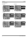
10.2 Octave Band Level
10.2.1 Indoor Units
FTKS35EVMA
70
OVER ALL ( dB )
60
50/60Hz
50/60Hz
SCALE 220-240/220-230V 220-240/220-230V
(H)
(L)
NC-60
NC-50
A
37
70
25
( B.G.N IS ALREADY RECTIFIED )
50
OPERATING CONDITIONS
NC-40
POWER SOURCE 220-240/220-230V 50/60Hz
40
JIS STANDARD
STANDARD EXTERNAL STATIC PRESSURE
50/60Hz 220-240/220-230V(H)
NC-30
30
50/60Hz 220-240/220-230V(L)
NC-20
20
APPROXIMATE
THRESHOLD HEARING
FOR CONTINUOUS
NOISE
63
125
250
500 1000 2000 4000
OCTAVE BAND CENTER FREQUENCY (Hz)
OCTAVE BAND SOUND PRESSURE LEVEL
dB(0dB=0.0002µ bar)
OCTAVE BAND SOUND PRESSURE LEVEL
dB(0dB=0.0002µ bar)
FTKS25EVMA
50/60Hz
50/60Hz
SCALE 220-240/220-230V 220-240/220-230V
(L)
(H)
NC-60
60
NC-50
A
38
26
( B.G.N IS ALREADY RECTIFIED )
50
OPERATING CONDITIONS
NC-40
POWER SOURCE 220-240/220-230V 50/60Hz
40
JIS STANDARD
STANDARD EXTERNAL STATIC PRESSURE
50/60Hz 220-240/220-230V(H)
NC-30
30
50/60Hz 220-240/220-230V(L)
NC-20
20
4D048279B
8000
OVER ALL ( dB )
APPROXIMATE
THRESHOLD HEARING
FOR CONTINUOUS
NOISE
63
125
250
500 1000 2000 4000
OCTAVE BAND CENTER FREQUENCY (Hz)
4D048280B
8000
FTXS25EVMA
COOLING
70
OVER ALL ( dB )
50/60Hz
SCALE 220-240/220-230V
(H)
NC-60
60
A
NC-50
50/60Hz
220-240/220-230V
(L)
37
25
( B.G.N IS ALREADY RECTIFIED )
50
OPERATING CONDITIONS
NC-40
POWER SOURCE
40
220-240/220-230V 50/60Hz
JIS STANDARD
STANDARD EXTERNAL STATIC PRESSURE
50/60Hz 220-240/220-230V(H)
NC-30
30
50/60Hz 220-240/220-230V(L)
Cooling
NC-20
20
APPROXIMATE
THRESHOLD HEARING
FOR CONTINUOUS
NOISE
63
125
250
500 1000 2000 4000
OCTAVE BAND CENTER FREQUENCY (Hz)
OCTAVE BAND SOUND PRESSURE LEVEL
dB(0dB=0.0002µ bar)
OCTAVE BAND SOUND PRESSURE LEVEL
dB(0dB=0.0002µ bar)
70
HEATING
OVER ALL ( dB )
50/60Hz
SCALE 220-240/220-230V
(H)
NC-60
60
A
NC-50
50/60Hz
220-240/220-230V
(L)
37
28
( B.G.N IS ALREADY RECTIFIED )
50
OPERATING CONDITIONS
NC-40
POWER SOURCE
40
220-240/220-230V 50/60Hz
JIS STANDARD
STANDARD EXTERNAL STATIC PRESSURE
50/60Hz 220-240/220-230V(H)
NC-30
30
50/60Hz 220-240/220-230V(L)
Heating
NC-20
20
APPROXIMATE
THRESHOLD HEARING
FOR CONTINUOUS
NOISE
63
8000
125
250
500 1000 2000 4000
OCTAVE BAND CENTER FREQUENCY (Hz)
3D048277B
8000
FTXS35EVMA
COOLING
70
OVER ALL ( dB )
50/60Hz
SCALE 220-240/220-230V
(H)
NC-60
60
A
NC-50
50/60Hz
220-240/220-230V
(L)
38
26
( B.G.N IS ALREADY RECTIFIED )
50
OPERATING CONDITIONS
NC-40
POWER SOURCE
40
220-240/220-230V 50/60Hz
JIS STANDARD
STANDARD EXTERNAL STATIC PRESSURE
50/60Hz 220-240/220-230V(H)
NC-30
30
50/60Hz 220-240/220-230V(L)
Cooling
NC-20
20
APPROXIMATE
THRESHOLD HEARING
FOR CONTINUOUS
NOISE
63
125
250
500 1000 2000 4000
OCTAVE BAND CENTER FREQUENCY (Hz)
Room Air Conditioners E-Series
8000
OCTAVE BAND SOUND PRESSURE LEVEL
dB(0dB=0.0002µ bar)
OCTAVE BAND SOUND PRESSURE LEVEL
dB(0dB=0.0002µ bar)
70
HEATING
OVER ALL ( dB )
50/60Hz
SCALE 220-240/220-230V
(H)
NC-60
60
A
NC-50
50/60Hz
220-240/220-230V
(L)
38
29
( B.G.N IS ALREADY RECTIFIED )
50
OPERATING CONDITIONS
NC-40
POWER SOURCE
40
220-240/220-230V 50/60Hz
JIS STANDARD
STANDARD EXTERNAL STATIC PRESSURE
50/60Hz 220-240/220-230V(H)
NC-30
30
50/60Hz 220-240/220-230V(L)
Heating
NC-20
20
APPROXIMATE
THRESHOLD HEARING
FOR CONTINUOUS
NOISE
63
125
250
500 1000 2000 4000
OCTAVE BAND CENTER FREQUENCY (Hz)
8000
3D048278B
25
Sound Level
ED04-805
10.2.2 Outdoor Units
RKS25EBVMA
RKS35EBVMA
NC-60
60
NC-50
SCALE
50/60Hz
220~240V(H)
A
46
( B.G.N IS ALREADY RECTIFIED )
50
OPERATING CONDITIONS
NC-40
POWER SOURCE
40
220~240V 50/60Hz
JIS STANDARD
NC-30
30
NC-20
20
70
OVER ALL ( dB )
APPROXIMATE
THRESHOLD HEARING
FOR CONTINUOUS
NOISE
63
125
250
500 1000 2000 4000
OCTAVE BAND CENTER FREQUENCY (Hz)
OCTAVE BAND SOUND PRESSURE LEVEL
dB(0dB=0.0002µ bar)
OCTAVE BAND SOUND PRESSURE LEVEL
dB(0dB=0.0002µ bar)
70
NC-60
60
NC-50
SCALE
50/60Hz
220~240V(H)
A
47
( B.G.N IS ALREADY RECTIFIED )
50
OPERATING CONDITIONS
NC-40
POWER SOURCE
40
220~240V 50/60Hz
JIS STANDARD
NC-30
30
NC-20
20
4D047727G
8000
OVER ALL ( dB )
APPROXIMATE
THRESHOLD HEARING
FOR CONTINUOUS
NOISE
63
125
250
500 1000 2000 4000
OCTAVE BAND CENTER FREQUENCY (Hz)
4D047728G
8000
RXS25EBVMA
COOLING
NC-60
60
NC-50
SCALE
50/60Hz
220~240V(H)
A
46
( B.G.N IS ALREADY RECTIFIED )
50
OPERATING CONDITIONS
NC-40
POWER SOURCE
40
220~240V 50/60Hz
JIS STANDARD
NC-30
30
Cooling
NC-20
20
70
OVER ALL ( dB )
APPROXIMATE
THRESHOLD HEARING
FOR CONTINUOUS
NOISE
63
125
250
500 1000 2000 4000
OCTAVE BAND CENTER FREQUENCY (Hz)
OCTAVE BAND SOUND PRESSURE LEVEL
dB(0dB=0.0002µ bar)
OCTAVE BAND SOUND PRESSURE LEVEL
dB(0dB=0.0002µ bar)
70
HEATING
OVER ALL ( dB )
NC-60
60
NC-50
SCALE
50/60Hz
220~240V(H)
A
47
( B.G.N IS ALREADY RECTIFIED )
50
OPERATING CONDITIONS
NC-40
POWER SOURCE
40
220~240V 50/60Hz
JIS STANDARD
NC-30
30
Heating
NC-20
20
APPROXIMATE
THRESHOLD HEARING
FOR CONTINUOUS
NOISE
63
8000
125
250
500 1000 2000 4000
OCTAVE BAND CENTER FREQUENCY (Hz)
3D047725H
8000
RXS35EBVMA
COOLING
NC-60
60
NC-50
50/60Hz
220~240V(H)
A
47
OPERATING CONDITIONS
NC-40
POWER SOURCE
40
220~240V 50/60Hz
JIS STANDARD
NC-30
30
Cooling
NC-20
APPROXIMATE
THRESHOLD HEARING
FOR CONTINUOUS
NOISE
63
26
SCALE
( B.G.N IS ALREADY RECTIFIED )
50
20
70
OVER ALL ( dB )
125
250
500 1000 2000 4000
OCTAVE BAND CENTER FREQUENCY (Hz)
8000
OCTAVE BAND SOUND PRESSURE LEVEL
dB(0dB=0.0002µ bar)
OCTAVE BAND SOUND PRESSURE LEVEL
dB(0dB=0.0002µ bar)
70
HEATING
OVER ALL ( dB )
NC-60
60
NC-50
SCALE
50/60Hz
220~240V(H)
A
48
( B.G.N IS ALREADY RECTIFIED )
50
OPERATING CONDITIONS
NC-40
POWER SOURCE
40
220~240V 50/60Hz
JIS STANDARD
NC-30
30
Heating
NC-20
20
APPROXIMATE
THRESHOLD HEARING
FOR CONTINUOUS
NOISE
63
125
250
500 1000 2000 4000
OCTAVE BAND CENTER FREQUENCY (Hz)
8000
3D047726H
Room Air Conditioners E-Series
ED04-805
Electric Characteristics
11. Electric Characteristics
Representative Unit Combination
Indoor Unit
FTKS25EVMA
FTKS35EVMA
FTXS25EVMA
FTXS35EVMA
Outdoor Unit
RKS25EBVMA
RKS35EBVMA
RXS25EBVMA
RXS35EBVMA
Power Supply
Hz-Volts
Voltage Range
COMP
MCA
MFA
RHz
RLA
OFM
IFM
W
FLA
W
FLA
23
0.22
40
0.14
23
0.22
40
0.14
23
0.22
40
0.14
23
0.22
40
0.14
3.5
50 - 220
50 - 230
50 - 240
MAX.50Hz 264V
MIN.50Hz 198V
60 - 220
60 - 230
MAX.60Hz 253V
MIN.60Hz 198V
50 - 220
50 - 230
50 - 240
MAX.50Hz 264V
MIN.50Hz 198V
3.3
9.75
10
48.5
3.2
3.5
3.3
4.4
4.2
9.75
60 - 220
60 - 230
MAX.60Hz 253V
MIN.60Hz 198V
50 - 220
50 - 230
50 - 240
MAX.50Hz 264V
MIN.50Hz 198V
60 - 220
60 - 230
MAX.60Hz 253V
MIN.60Hz 198V
50 - 220
50 - 230
50 - 240
MAX.50Hz 264V
MIN.50Hz 198V
60 - 220
60 - 230
MAX.60Hz 253V
MIN.60Hz 198V
10
75.0
4.0
4.4
4.2
3.5
3.3
9.75
10
48.5
3.2
3.5
3.3
4.4
4.2
9.75
10
75.0
4.0
4.4
4.2
SYMBOLS:
NOTE:
MCA
1. RLA is based on the following conditions.
Indoor temp. 27°CDB/19°CWB
Outdoor temp. 35°CDB.
2. Maximum allowable voltage variation between phases is 2%.
3. Select wire size based on the larger value of MCA.
4. Instead of fuse, use circuit breaker.
5. Be sure to install an earth leak detector. (One that can handle
higher harmonics.)
(This unit uses an inverter, which means that it must be used an
earth leak detector capable handling high harmonics in order to
prevent malfunctioning of the earth leak detector itself.)
: MIN. CIRCUIT AMPS (A)
MFA
: MAX. FUSE AMPS (A)
RLA
: RATED LOAD AMPS (A)
OFM
: OUTDOOR FAN MOTOR
IFM
: INDOOR FAN MOTOR
FLA
: FULL LOAD AMPS (A)
W
: FAN MOTOR RATED OUTPUT (W)
RHz
: RATED OPERATING FREQUENCY (Hz)
3D049968D
3D049969D
Room Air Conditioners E-Series
27
Installation Manual
ED04-805
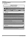
12. Installation Manual
12.1 Indoor Units
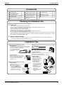
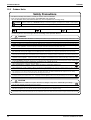
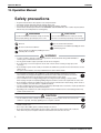
Safety Precautions
• Read these Safety Precautions carefully to ensure correct installation.
• This manual classifies the precautions into WARNING and CAUTION.
Be sure to follow all the precautions below: they are all important for ensuring safety.
WARNING
Failure to follow any of WARNING is likely to result in such grave consequences as death or serious injury.
CAUTION
Failure to follow any of CAUTION may result in grave consequences in some cases.
• The following safety symbols are used throughout this manual:
Be sure to observe this instruction.
Be sure to establish an earth connection.
Never attempt.
• After completing installation, test the unit to check for installation errors. Give the user adequate instructions
concerning the use and cleaning of the unit according to the Operation Manual.
WARNING
• Installation should be left to the dealer or another professional. Improper installation may cause water leakage, electrical shock, or fire.
• Install the air conditioner according to the instructions given in this manual. Incomplete installation may cause water leakage, electrical shock, or fire.
• Be sure to use the supplied or specified installation parts. Use of other parts may cause the unit to come to lose, water leakage, electrical shock, or fire.
• Install the air conditioner on a solid base that can support the weight of the unit. An inadequate base or incomplete installation may cause injury in the event the unit falls off the base.
• Electrical work should be carried out in accordance with the installation manual and the national electrical wiring
rules or code of practice. Insufficient capacity or incomplete electrical work may cause electrical shock or fire.
• Be sure to use a dedicated power circuit. Never use a power supply shared by another appliance.
• For wiring, use a cable length enough to cover the entire distance with no connection. Do not use an extension cord.
Do not put other loads on the power supply, use a dedicated power circuit. (Failure to do so may cause abnormal heat, electric shock or fire.)
• Use the specified types of wires for electrical connections between the indoor and outdoor units.
Firmly clamp the interconnecting wires so their terminals receive no external stresses. Incomplete connections or clamping may cause terminal overheating or fire.
• After connecting interconnecting and supply wiring be sure to shape the cables so that they do not put undue force on the
electrical covers or panels. Install covers over the wires. Incomplete cover installation may cause terminal overheating, electrical shock, or fire.
• When installing or relocating the system, be sure to keep the refrigerant circuit free from substances other than the specified
refrigerant (R410A), such as air. (Any presence of air or other foreign substance in the refrigerant circuit causes an abnormal pressure rise or rupture, resulting in injury.)
• The installation height from the floor must be over 1.8m.
• If any refrigerant has leaked out during the installation work, ventilate the room.
(The refrigerant produces a toxic gas if exposed to flames.)
• After all installation is complete, check to make sure that no refrigerant is leaking out.
(The refrigerant produces a toxic gas if exposed to flames.)
• During pump-down, stop the compressor before removing the refrigerant piping. If the compressor is still running and the shut-off valve is open during
pump-down, air will be sucked in when the refrigerant piping is removed, causing abnormal pressure in the freezer cycle which will lead to breakage and even injury.
• During installation, attach the refrigerant piping securely before running the compressor. If the compressor is not attached and the shut-off valve is
open during pump-down, air will be sucked in when the compressor is run, causing abnormal pressure in the freezer cycle which will lead to breakage and even injury.
• Be sure to establish an earth. Do not earth the unit to a utility pipe, arrester, or telephone earth.
Incomplete earth may cause electrical shock, or fire. A high surge current from lightning or other sources may cause damage to the air conditioner.
• Be sure to install an earth leakage breaker. Failure to install an earth leakage breaker may result in electric shocks, or fire.
CAUTION
• Do not install the air conditioner in a place where there is danger of exposure to inflammable gas leakage.
If the gas leaks and builds up around the unit, it may catch fire.
• Establish drain piping according to the instructions of this manual. Inadequate piping may cause flooding.
• Note for installing the outdoor unit. (For heat pump model only.) In cold area where the outside air temperature keep below or around
freezing-point for a few days, the outdoor unit’s drain may freeze. If so, it is recommended to install an electric heater in order to protect drain from freezing.
• Tighten the flare nut according to the specified method such as with a torque wrench.
If the flare nut is tightened too hard, the flare nut may crack after a long time and cause refrigerant leakage.
28
Room Air Conditioners E-Series
ED04-805
Installation Manual
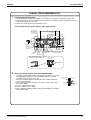
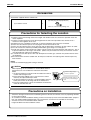
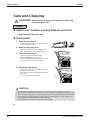
Accessories
A Mounting plate
Mounting plate fixing
B
screws M4 × 25L
Titanium Apatite Photocatalytic
C
Air-Purifying Filter
D Wireless remote controller
1
E Remote controller holder
1
J
Insulation tape
1
6
Fixing screws for remote
F
controller holder M3 × 20L
2
K Operation manual
1
2
G AAA dry-cell batteries
2
L Installation manual
1
1
H
Indoor unit fixing screws
M4 × 12L
2
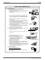
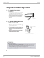
Choosing an Installation Site
• Before choosing the installation site, obtain user approval.
1.
Indoor unit.
•
1)
2)
3)
4)
5)
6)
7)
8)
9)
2.
The indoor unit should be sited in a place where:
the restrictions on installation specified in the indoor unit installation drawings are met,
both air intake and exhaust have clear paths met,
the unit is not in the path of direct sunlight,
the unit is away from the source of heat or steam,
there is no source of machine oil vapour (this may shorten indoor unit life),
cool (warm) air is circulated throughout the room,
the unit is away from electronic ignition type fluorescent lamps (inverter or rapid start type) as they may shorten the remote controller range,
the unit is at least 1 metre away from any television or radio set (unit may cause interference with the picture or sound),
install at the recommended height (1.8m).
Wireless remote controller.
1) Turn on all the fluorescent lamps in the room, if any, and find the site where remote controller signals are
properly received by the indoor unit (within 7 metres).
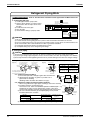
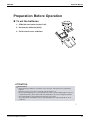
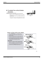
Installation Tips
<When there is no work space because the unit is close to ceiling>
1. Removing and installing front panel.
• Removal method
Hook fingers on the panel protrusions on the left and right
of the main body, and open until the panel stops. Slide
the front panel sideways to disengage
the rotating shaft. Then pull
the front panel toward you
to remove it.
CAUTION
1) Push up.
Be sure to wear protection gloves.
Place both hands under the center of the front
grille, and while pushing up, pull it toward you.
2) Pull toward you.
• Installation method
1) Install the front grille and firmly engage the upper hooks (3 locations).
2) Install 2screws of the front grille.
3) Install the air filter and then mount the front panel.
• Installation method
2. Removing and installing front grille.
• Removal method
{{{ mark area
(3 locations)
Upper hook
1)Remove front panel to remove the air filter.
2)Remove the front grille.
3)In front of the
mark of the
front grille, there are 3 upper
hooks. Lightly pull the front grille
pull the front
toward you with one hand, and Lightly
grille toward you with
one hand, and push
push down on the hooks with
down on the hooks with
fingers of your other
the fingers of your other hand. the
hand. (3 locations)
Push
down.
Upper hook
Upper hook
When two indoor units are
installed in one room, the
two wireless remote
controllers can be set for
different addresses.
1) In the same way as
when connecting to an
HA system, remove the
metal plate electrical
wiring cover.
2) Cut the address jumper
(JA) on the printed
circuit board.
3) Cut the address jumper
(J4) in the remote
controller.
ADDRESS
3. How to set the
different addresses.
Push the
rotating shaft
of the front
panel into the
groove.
JA
Align the tabs of the front panel with the
grooves, and push all the way in. Then
close slowly. Push the center of the
lower surface of the panel firmly to
engage the tabs.
JA ADDRESS
EXIST
CUT
1
2
J4
J4 ADDRESS
EXIST
CUT
Room Air Conditioners E-Series
1
2
29
Installation Manual
ED04-805
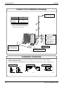
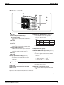
Indoor Unit Installation Drawings
How to attach the indoor unit.
Hook the claws of the bottom frame
to the mounting plate.
If the claws are difficult to hook,
remove the front grille.
How to remove the indoor unit.
Push up the marked area (at the
lower part of the front grille) to
release the claws. If it is difficult to Front grille
release, remove the front grille.
A Mounting plate
A Mounting
plate
Clip
Bottom frame
Mark (rear side)
The mounting plate
should be installed on a
wall which can support the
weight of the indoor unit.
B Mounting plate fixing
screws M4 × 25L (6)
Caulk
pipe hole
gap
with putty.
30mm or more from ceiling
Cut thermal insulation
pipe to an appropriate
length and wrap it with
tape, making sure that no
gap is left in the insulation
pipe’s cut line.
Front panel
Wrap the insulation pipe with
the finishing tape from bottom
to top.
50mm or more from walls
(on both sides)
Intelligent-eye sensor
M4 × 16L
Air filters
Service lid
Opening service lid
Service lid is opening/closing type.
Opening method
1) Remove the service lid screws.
2) Pull out the service lid diagonally
down in the direction of the arrow.
3) Pull down.
C Titanium Apatite Photocatalytic
Air-Purifying Filter (2)
C Titanium Apatite
Photocatalytic
Air-Purifying Filter
Air filter
Filter frame
D Wireless
remote controller
Tab
F Fixing screws for
remote controller
holder M3 × 20L (2)
Before screwing the remote
controller holder to the wall,
make sure that control
signals are properly
received by indoor unit.
E
Remote
controller holder
Intelligent-eye Sensor
CAUTION
1) Do not hit or violently push the intelligent-eye sensor. This can lead to damage and malfunction.
2) Do not place large objects near the sensor. Also keep heating units or humidifiers outside the
sensor’s detection area.
30
Room Air Conditioners E-Series
ED04-805
Installation Manual
Indoor Unit Installation (1)
1.
Installing the mounting plate.
• The mounting plate should be installed on a wall which can support the weight of the indoor unit.
1) Temporarily secure the mounting plate to the wall, make sure that the panel is completely level, and
mark the boring points on the wall.
2) Secure the mounting plate to the wall with screws.
Recommended mounting plate retention spots and dimensions
450
Recommended
mounting plate
retention spots
(6 spots in all)
100
400
(Bolt size : M10)
135
110
φ65
60
φ65
130
220
60
44.5
Use tape
measure
as shown.
Position the
end of a tape
measure at ∇.
131.5
44.5 87
283
47.5
46.5
(Bolt size : M10)
50.5
80
141.5
Place a leveler
on raised tab.
110
50
800
Drain hose
position
Throughthe-wall
hole φ65mm
Liquid pipe end Keep here the piece cut out
from the unit for piping
Gas pipe end
* The removed pipe port cover can be
kept in the mounting plate pocket.
Removed pipe
port cover
A Mounting plate
2.
Boring a wall hole and installing wall embedded pipe.
• For walls containing metal frame or metal board, be sure to use a wall
embedded pipe and wall cover in the feed-through hole to prevent
possible heat, electrical shock, or fire.
• Be sure to caulk the gaps around the pipes with caulking material to
prevent water leakage.
1) Bore a feed-through hole of 65mm in the wall so it has a down slope
toward the outside.
2) Insert a wall pipe into the hole.
3) Insert a wall cover into wall pipe.
4) After completing refrigerant piping, wiring, and drain piping, caulk pipe
hole gap with putty.
Room Air Conditioners E-Series
Inside
Wall embedded pipe
(Field supply)
Outside
Caulking
φ65
Wall hole cover
(Field supply)
Wall embedded pipe
(Field supply)
31
Installation Manual
ED04-805
Indoor Unit Installation (2)
3.
Installing indoor unit.
3-1. Right-side, right-back, or right-bottom piping.
1) Attach the drain hose to the underside of the refrigerant pipes
with an adhesive vinyl tape.
2) Wrap the refrigerant pipes and drain hose together with an
insulation tape.
Right-back piping
Remove pipe port cover
here for right-side piping.
Right-bottom
piping
Remove pipe port cover
here for right-bottom piping.
Bind coolant pipe
and drain hose
together with
insulating tape.
A Mounting plate
3) Pass the drain hose and refrigerant pipes through the wall
hole, then set the indoor unit on the mounting plate hooks by
using the markings at the top of the indoor unit as a guide.
4) Open the front panel, then open the service lid. (Refer to
Installation Tips.)
5) Pass the interconnecting wires from the outdoor unit through
the feed-through wall hole and then through the back of the
indoor unit. Pull them through the front side.
Bend the ends of tie wires upward for easier work in advance.
(If the interconnecting wire ends are to be stripped first, bundle
wire ends with adhesive tape.)
6) Press the bottom frame of the indoor unit with both hands to
set it on the mounting plate hooks. Make sure that the wires do
not catch on the edge of the indoor unit.
Hang indoor unit’s hook here.
A Mounting plate
When stripping the
ends of interconnecting
wires in advance, bind
right ends of wires with
insulating tape.
Interconnecting
wires
Wire guide
3-2. Left-side, left-back, or left-bottom piping.
1) Attach the drain hose to the underside of the refrigerant pipes
with adhesive vinyl tape.
Remove pipe
port cover
here for leftside piping.
Left-side
piping
Left-back
piping
Remove pipe port cover here for left-bottom piping.
Left-bottom piping
2) Be sure to connect the drain hose to the drain port in place of
a drain plug.
3) Shape the refrigerant pipe along the pipe path
marking on the mounting plate.
4) Pass drain hose and refrigerant pipes through
the wall hole, then set the indoor unit on
Drain
hose
mounting plate hooks, using the markings at
Caulk this hole
with
putty
or
the top of indoor unit as a guide.
caulking material.
5) Pull in the interconnecting wires.
6) Connect the inter-unit piping.
7) Wrap the refrigerant pipes and drain hose together with
insulation tape as right figure, in case of setting the drain hose
through the back of the indoor unit.
8) While exercising care so that the interconnecting wires do not catch
indoor unit, press the bottom edge of indoor unit with both hands until
it is firmly caught by the mounting plate hooks. Secure indoor unit to
the mounting plate with the screws (M4 × 12L).
3-3. Wall embedded piping.
Follow the instructions given under
Left-side, left-back, or left-bottom piping
1) Insert the drain hose to this depth so it won’t be pulled out of
the drain pipe.
32
How to set drain plug
ap
No g
Do not apply lubricating
oil (refrigerant machine
oil) when inserting.
Application of causes
deterioration and drain
leakage of the plug.
Insert a hexagon wrench (4mm)
A Mounting plate
Bind with plastic
tape.
Wrap insulating tape around the
bent portion of refrigerant pipe.
Overlap at least half the width
of the tape with each turn.
Drain hose
A
Mounting
plate
Refrigerant
pipes
Bottom frame
H M4 × 12L (2 point)
Insert drain hose
to this depth so
it won’t be pulled
out of drain pipe.
50mm
or more
Outer wall
Inner wall
Drain hose
Vinyl chloride
drain pipe
(VP-30)
Room Air Conditioners E-Series
ED04-805
Installation Manual
Indoor Unit Installation (3)
With a multi indoor unit
4.
, install as described in the installation manual supplied with the Multi outdoor unit.
Terminal block
Wiring.
1) Strip wire ends (15mm).
2) Match wire colours with terminal numbers on indoor and outdoor unit’s
terminal blocks and firmly screw wires to the corresponding terminals.
3) Connect the earth wires to the corresponding terminals.
Attach the earth wire so that it is not connected to the fan
motor connector.
4) Pull wires to make sure that they are securely latched up,
then retain wires with wire retainer.
5) In case of connecting to an adapter system. Run the remote
controller cable and attach the S21.
(Refer to 5. When connecting to an HA system.)
6) Shape the wires so that the service lid fits securely, then close service lid.
Electrical component box
Shape wires so that the service lid
will fit securely.
Connector for fan motor
Firmly secure wire retainer so that
wires sustain no external stress.
Wire retainer
Use the
specified wire type.
Firmly fix the wires with
the terminal screws.
Outdoor unit
1 23
When wire length exceeds
10m, use 2.0mm diameter wires.
Indoor
unit
LN
1
2
3
Firmly fix the wires with
the terminal screws.
H05VV
WARNING
1) Do not use tapped wires, stranded wires, extensioncords, or starburst connections, as they may cause
overtheating, electrical shock,or fire.
2) Do not use locally purchased electrical parts inside the product. (Do not branch the power for the drain pump, etc.,
from the terminal block.) Doing so may cause electric shock or fire.
5.
When connecting to an HA system.
1) Remove the front grille.
Tab
(2 screws)
Notched part
Push
2) Remove the electrical
Slide
wiring box. (1 screw)
3) Remove the metal plate
HA connector
(S21)
electrical wiring cover.
(3 tabs)
Slide
4) Attach the connection
4) Attach the connection cord to
cord to the S21 connector 3) Remove the metal Screw
Pull
the S21 connector and pull the
plate electrical
Tab
harness out through the
wiring cover.
and pull the harness out
notched part in the figure.
through the notched part
in the figure.
5) Replace the electrical wiring cover as it was, and pull the harness
around, as shown in the figure.
5) Replace the electrical
wiring cover as it was,
and pull the harness
around, as shown
in the figure.
Drain piping.
1) Connect the drain hose, as described below.
The drain hose should
be inclined downward.
3) When drain hose requires extension, obtain
an extension hose commercially available.
Be sure to thermally insulate the indoor
section of the extension hose.
No trap is permitted.
Indoor unit
drain hose
φ18
6.
HA cord
Extension drain hose
Do not put the end
of the hose in water.
Heat insulation tube
(Field supply)
4) When connecting a rigid polyvinyl chloride pipe
(nominal diameter 13mm) directly to the drain
hose attached to the indoor unit as with embedded
piping work, use any commercially available drain
socket (nominal diameter 13mm) as a joint.
φ18
2) Remove the air filters and pour some water
into the drain pan to check the water flows
smoothly.
Drain hose supplied with
the indoor unit
Room Air Conditioners E-Series
Commercially available drain
socket
(nominal diameter 13mm)
Commercially available rigid
polyvinyl chloride pipe
(nominal diameter 13mm)
33
Installation Manual
ED04-805
Refrigerant Piping Work
With a multi indoor unit
1.
, install as described in the installation manual supplied with the Multi outdoor unit.
Flaring the pipe end.
1) Cut the pipe end with a pipe cutter.
2) Remove burrs with the cut surface facing
downward so that the chips do not enter
the pipe.
3) Put the flare nut on the pipe.
4) Flare the pipe.
5) Check that the flaring is properly made.
(Cut exactly at
right angles.)
Remove burrs
Flaring
Set exactly at the position shown below.
A
Die
Flare tool for R410A
Conventional flare tool
Clutch-type
Clutch-type (Rigid-type) Wing-nut type (Imperial-type)
A
0-0.5mm
1.0-1.5mm
1.5-2.0mm
Check
Flare’s inner
surface must
be flaw-free.
The pipe end must
be evenly flared in
a perfect circle.
Make sure that the
flare nut is fitted.
WARNING
1)
2)
3)
4)
5)
6)
2.
Do not use mineral oil on flared part.
Prevent mineral oil from getting into the system as this would reduce the lifetime of the units.
Never use piping which has been used for previous installations. Only use parts which are delivered with the unit.
Do never install a drier to this R410A unit in order to guarantee its lifetime.
The drying material may dissolve and damage the system.
Incomplete flaring may cause refrigerant gas leakage.
Refrigerant piping
CAUTION
1) Use the flare nut fixed to the main unit. (To prevent cracking of the flare nut by aged deterioration.)
2) To prevent gas leakage, apply refrigeration oil only to the inner surface of the flare. (Use refrigeration oil for R410A.)
3) Use torque wrenches when tightening the flare nuts to prevent damage to the flare nuts and gas leakage.
Align the centres of both flares and tighten the flare nuts 3 or 4 turns by hand. Then tighten them fully with the torque wrenches.
[Apply oil]
Do not apply refrigeration
oil to the outer surface.
Apply refrigeration
oil to the inner
surface of the flare.
[Tighten]
Torque wrench
Flare nut tightening torque
Flare nut
Gas side
Spanner
Piping union
Do not apply refrigeration oil to the flare
nut avoid tightening with over torque.
Liquid side
3/8 inch
1/4 inch
32.7-39.9N • m
14.2-17.2N • m
(330-407kgf • cm)
(144-175kgf • cm)
Flare nut
2-1. Caution on piping handling.
Be sure to
1) Protect the open end of the pipe against dust and moisture.
place a cap.
2) All pipe bends should be as gentle as possible. Use a
Rain
If no flare cap is
available, cover
pipe bender for bending.
the flare mouth
with tape to keep
(Bending radius should be 30 to 40mm or larger.)
dirt or water out.
2-2. Selection of copper and heat insulation materials.
Inter-unit wiring
• When using commercial copper pipes and fittings, observe the following:
1) Insulation material: Polyethylene foam
Gas pipe
Heat transfer rate: 0.041 to 0.052W/mK (0.035 to 0.045kcal/(mh • °C))
Refrigerant gas pipe’s surface temperature reaches 110°C max.
Choose heat insulation materials that will withstand this temperature.
2) Be sure to insulate both the gas and liquid piping and to provide
Gas pipe
insulation dimensions as below.
insulation
Gas side
25/35 class
O.D. 9.5mm
Liquid side
O.D. 6.4mm
Thickness 0.8mm
Gas pipe thermal insulation
25/35 class
Liquid pipe thermal
insulation
I.D. 12-15mm
I.D. 8-10mm
Finishing tape
Wall
Liquid pipe
Liquid pipe
insulation
Drain hose
Thickness 10mm Min.
3) Use separate thermal insulation pipes for gas and liquid refrigerant pipes.
34
Room Air Conditioners E-Series
ED04-805
Installation Manual
Trial Operation and Testing
1.
Trial operation and testing.
1-1 Measure the supply voltage and make sure that it falls in the specified range.
1-2 Trial operation should be carried out in either cooling or heating mode.
For Heat pump
• In cooling mode, select the lowest programmable temperature; in heating mode, select the highest
programmable temperature.
1) Trial operation may be disabled in either mode depending on the room temperature.
Use the remote controller for trial operation as described below.
2) After trial operation is complete, set the temperature to a normal level (26˚C to 28˚C in cooling mode,
20˚C to 24˚C in heating mode).
3) For protection, the system disables restart operation for 3 minutes after it is turned off.
For Cooling only
• Select the lowest programmable temperature.
1) Trial operation in cooling mode may be disabled depending on the room temperature.
Use the remote controller for trial operation as described below.
2) After trial operation is complete, set the temperature to a normal level (26˚C to 28˚C).
3) For protection, the system disables restart operation for 3 minutes after it is turned off.
1-3 Carry out the test operation in accordance with the operation manual to ensure that all functions and
parts, such as louver movement, are working properly.
• The air conditioner requires a small amount of power in its standby mode. If the system is not to be used for
some time after installation, shut off the circuit breaker to eliminate unnecessary power consumption.
• If the circuit breaker trips to shut off the power to the air conditioner, the system will restore the original
operation mode when the circuit breaker is opened again.
Trial operation from remote controller.
1) Press ON/OFF button to turn on the system.
2) Simultaneously press centre of TEMP button and MODE button.
3) Press MODE button twice.
(“ ” will appear on the display to indicate that Trial Operation mode is selected.)
4) Trial run mode terminates in approx. 30 minutes and switches into normal mode. To quit a trial
operation, press ON/OFF button.
2.
Test items.
Test items
Symptom
(diagnostic display on RC)
Indoor and outdoor units are installed properly on
solid bases.
Fall, vibration, noise
No refrigerant gas leaks.
Incomplete cooling/heating function
Refrigerant gas and liquid pipes and indoor drain
hose extension are thermally insulated.
Water leakage
Draining line is properly installed.
Water leakage
System is properly earthed.
Electrical leakage
The specified wires are used for interconnecting
wire connections.
Inoperative or burn damage
Indoor or outdoor unit’s air intake or exhaust has
clear path of air. Shut-off valves are opened.
Incomplete cooling/heating function
Indoor unit properly receives remote controller
commands.
Inoperative
Check
3P175978-5D
Room Air Conditioners E-Series
35
Installation Manual
ED04-805
12.2 Outdoor Units
Safety Precautions
• Read these Safety Precautions carefully to ensure correct installation.
• This manual classifies the precautions into WARNING and CAUTION.
Be sure to follow all the precautions below: they are all important for ensuring safety.
WARNING Failure to follow any of WARNING is likely to result in such grave consequences as death or serious injury.
CAUTION
Failure to follow any of CAUTION may result in grave consequences in some cases.
• The following safety symbols are used throughout this manual:
Be sure to observe this instruction.
Be sure to establish an earth connection.
Never attempt.
• After completing installation, test the unit to check for installation errors. Give the user adequate instructions
concerning the use and cleaning of the unit according to the Operation Manual.
WARNING
• Installation should be left to the dealer or another professional. Improper installation may cause water leakage, electrical shock, or fire.
• Install the air conditioner according to the instructions given in this manual. Incomplete installation may cause water leakage, electrical shock, or fire.
• Be sure to use the supplied or specified installation parts. Use of other parts may cause the unit to come to lose, water leakage, electrical shock, or fire.
• Install the air conditioner on a solid base that can support the weight of the unit. An inadequate base or incomplete installation may cause injury in the event the unit falls off the base.
• Electrical work should be carried out in accordance with the installation manual and the national electrical wiring
rules or code of practice. Insufficient capacity or incomplete electrical work may cause electrical shock or fire.
• Be sure to use a dedicated power circuit. Never use a power supply shared by another appliance.
• For wiring, use a cable length enough to cover the entire distance with no connection. Do not use an extension cord. Do not
put other loads on the power supply, use a dedicated power circuit.(Failure to do so may cause abnormal heat, electric shock or fire.)
• Use the specified types of wires for electrical connections between the indoor and outdoor units.
Firmly clamp the interconnecting wires so their terminals receive no external stresses. Incomplete connections or clamping may cause terminal overheating or fire.
• After connecting interconnecting and supply wiring be sure to shape the cables so that they do not put undue force on the
electrical covers or panels. Install covers over the wires. Incomplete cover installation may cause terminal overheating, electrical shock, or fire.
• When installing or relocating the system, be sure to keep the refrigerant circuit free from substances other than the specified
refrigerant (R410A), such as air. (Any presence of air or other foreign substance in the refrigerant circuit causes an abnormal pressure rise or rupture, resulting in injury.)
• If any refrigerant has leaked out during the installation work, ventilate the room.
(The refrigerant produces a toxic gas if exposed to flames.)
• After all installation is complete, check to make sure that no refrigerant is leaking out.
(The refrigerant produces a toxic gas if exposed to flames.)
• During pump-down, stop the compressor before removing the refrigerant piping. If the compressor is still running and the stop valve is open during
pump-down, air will be sucked in when the refrigerant piping is removed, causing abnormal pressure in the freezer cycle which will lead to breakage and even injury.
• During installation, attach the refrigerant piping securely before running the compressor.
If the compressor is not attached and the stop valve is open during pump-down, air will be sucked in when the compressor is run, causing
abnormal pressure in the freezer cycle which will lead to breakage and even injury.
• Be sure to establish an earth. Do not earth the unit to a utility pipe, arrester, or telephone earth.
Incomplete earth may cause electrical shock, or fire.
A high surge current from lightning or other sources may cause damage to the air conditioner.
• Be sure to install an earth leakage breaker. Failure to install an earth leakage breaker may result in electric shocks, or fire.
CAUTION
• Do not install the air conditioner in a place where there is danger of exposure to inflammable gas leakage.
If the gas leaks and builds up around the unit, it may catch fire.
• Establish drain piping according to the instructions of this manual. Inadequate piping may cause flooding.
• Tighten the flare nut according to the specified method such as with a torque wrench.
If the flare nut is tightened too hard, the flare nut may crack after a long time and cause refrigerant leakage.
• Make sure to provide for adequate measures in order to prevent that the outdoor unit be used as a shelter by small animals.
Small animals making contact with electrical parts can cause malfunctions, smoke or fire. Please instruct the customer to keep the area around the unit clean.
36
Room Air Conditioners E-Series
ED04-805
Installation Manual
Accessories
Accessories supplied with the outdoor unit:
(B) Drain plug (Heat pump-Models)
(A) Installation manual
1
1
There is on the bottom packing case.
Precautions for Selecting the Location
1) Choose a place solid enough to bear the weight and vibration of the unit, where the operation noise will
not be amplified.
2) Choose a location where the hot air discharged from the unit or the operation noise will not cause a
nuisance to the neighbors of the user.
3) Avoid places near a bedroom and the like, so that the operation noise will cause no trouble.
4) There must be sufficient spaces for carrying the unit into and out of the site.
5) There must be sufficient space for air passage and no obstructions around the air inlet and the air outlet.
6) The site must be free from the possibility of flammable gas leakage in a nearby place.
7) Install units, power cords and inter-unit cables at least 3 meter away from television and radio sets. This is
to prevent interference to images and sounds. (Noises may be heard even if they are more than 3 meter
away depending on radio wave conditions.)
8) In coastal areas or other places with salty atmosphere of sulfate gas, corrosion may shorten the life of the
air conditioner.
9) Since drain flows out of the outdoor unit, do not place under the unit anything which must be kept away
from moisture.
NOTE
Cannot be installed hanging from ceiling or stacked.
CAUTION
When operating the air conditioner in a low outdoor ambient
temperature, be sure to follow the instructions described
below.
1) To prevent exposure to wind, install the outdoor unit with its
suction side facing the wall.
2) Never install the outdoor unit at a site where the suction
side may be exposed directly to wind.
3) To prevent exposure to wind, it is recommended to install a
baffle plate on the air discharge side of the outdoor unit.
4) In heavy snowfall areas, select an installation site where the
snow will not affect the unit.
Construct a large canopy.
Construct a pedestal.
Install the unit high enough off
the ground to prevent burying in
snow.
Precautions on Installation
20
• Check the strength and level of the installation ground so that the unit will not cause any operating vibration
or noise after installed.
• In accordance with the foundation drawing, fix the unit securely by means of the foundation bolts. (Prepare
four sets of M8 or M10 foundation bolts, nuts and washers each which are available on the market.)
• It is best to screw in the foundation bolts until their
length are 20mm from the foundation surface.
Room Air Conditioners E-Series
37
Installation Manual
ED04-805
Outdoor Unit Installation Drawings
Wrap the insulation pipe with
the finishing tape from bottom
to top.
Max. allowable length
Max. allowable height
20m
15m
Additional refrigerant
required for refrigerant
pipe exceeding
10m in length.
20g/m
Gas pipe
Liquid pipe
O.D. 9.5mm
O.D. 6.4mm
* Be sure to add the proper amount of additional refrigerant.
Failure to do so may result in reduced performance.
** When connecting the FVXS indoor unit, the shortest piping
length should be no less than around 2.5m.
Stop valve cover
How to remove the stop valve cover.
Remove the screw on the
stop valve cover.
Slide the lid downward
to remove it.
250mm from wa
ll
3
Foo 11
cen t bolt
tres -hol
e
How to attach the stop valve cover.
Insert the upper part of the
stop valve cover into the
outdoor unit to install.
Tighten the screws.
In sites with poor drainage, use
block bases for outdoor unit.
Adjust foot height until the unit
is leveled. Otherwise, water
leakage or pooling of water may
occur.
574
lt-hole
centre
s)
(Foot b
o
Allow space for piping
and electrical servicing.
105.5
(From
u
nit’s s
ide)
Where there is a danger of the unit
falling, use foot bolts, or wires.
Unit: mm
Installation Guidelines
• Where a wall or other obstacle is in the path of outdoor unit’s intake or exhaust airflow, follow the
installation guidelines below.
• For any of the below installation patterns, the wall height on the exhaust side should be 1200mm or less.
Wall facing one side
More than 50
Walls facing two sides
More than 100
More than 50
More than 50
Side view
More than 150
More than 150
More
than 100
1200
or less
38
Walls facing three sides
More than 50
Top view
More than 300
Top view
Unit: mm
Room Air Conditioners E-Series
ED04-805
Installation Manual
Outdoor Unit Installation (1)
1.
Installing outdoor unit.
1) When installing the outdoor unit, refer to “Precautions for Selecting the Location” and the “Outdoor
Unit Installation Drawings”.
2) If drain work is necessary, follow the procedures below.
2.
Drain work (Heat pump-models).
1) Use drain plug for drainage.
2) If the drain port is covered by a mounting base or floor surface, place
additional foot bases of at least 30mm in height under the outdoor unit’s feet.
3) In cold areas, do not use a drain hose with the outdoor unit.
(Otherwise, drain water may freeze, impairing heating performance.)
3.
Drain-water hole
Bottom frame
Drain plug
Hose (available commercially,
inner dia. 16mm)
Flaring the pipe end.
(Cut exactly at
right angles.)
1) Cut the pipe end with a pipe cutter.
2) Remove burrs with the cut surface
facing downward so that the chips do
not enter the pipe.
3) Put the flare nut on the pipe.
4) Flare the pipe.
5) Check that the flaring is properly made.
Remove burrs
Flaring
Set exactly at the position shown below.
A
Die
A
Flare tool for R410A
Conventional flare tool
Clutch-type
Clutch-type (Rigid-type) Wing-nut type (Imperial-type)
0-0.5mm
1.0-1.5mm
1.5-2.0mm
Check
Flare’s inner
surface must
be flaw-free.
The pipe end must
be evenly flared in
a perfect circle.
Make sure that the
flare nut is fitted.
WARNING
1) Do not use mineral oil on flared part.
2) Prevent mineral oil from getting into the system as this would reduce the lifetime of the units.
3) Never use piping which has been used for previous installations. Only use parts which are delivered with the unit.
4) Do never install a drier to this R410A unit in order to guarantee its lifetime.
5) The drying material may dissolve and damage the system.
6) Incomplete flaring may cause refrigerant gas leakage.
4.
Refrigerant piping.
CAUTION
1) Use the flare nut fixed to the main unit. (To prevent cracking of the flare nut by aged deterioration.)
2) To prevent gas leakage, apply refrigeration oil only to the inner surface of the flare. (Use refrigeration oil
for R410A.)
3) Use torque wrenches when tightening the flare nuts to prevent damage to the flare nuts and gas leakage.
Align the centres of both flares and tighten the flare nuts 3 or 4 turns by hand. Then tighten them fully
with the torque wrenches.
[Apply oil]
Do not apply refrigeration
oil to the outer surface.
[Tighten]
Apply refrigeration oil to the
inner surface of the flare.
Torque wrench
Flare nut
Spanner
Piping union
Do not apply refrigeration oil to the flare
Flare nut
nut avoid tightening with over torque.
Flare nut tightening torque
Gas side
Liquid side
3/8 inch
1/4 inch
32.7-39.9N • m
14.2-17.2N • m
(330-407kgf • cm)
(144-175kgf • cm)
Valve cap tightening torque
Gas side
Liquid side
3/8 inch
1/4 inch
21.6-27.4N • m
21.6-27.4N • m
(220-280kgf • cm)
(220-280kgf • cm)
Service port cap
tightening torque
Room Air Conditioners E-Series
10.8-14.7N • m
(110-150kgf • cm)
39
Installation Manual
ED04-805
Outdoor Unit Installation (2)
5.
Purging air and checking gas leakage.
• When piping work is completed, it is necessary to purge the air and check for gas leakage.
WARNING
1) Do not mix any substance other than the specified refrigerant (R410A) into the refrigeration cycle.
2) When refrigerant gas leaks occur, ventilate the room as soon and as much as possible.
3) R410A, as well as other refrigerants, should always be recovered and never be released directly into the
environment.
4) Use a vacuum pump for R410A exclusively. Using the same vacuum pump for different refrigerants
may damage the vacuum pump or the unit.
• If using additional refrigerant, perform air purging from the refrigerant
pipes and indoor unit using a vacuum pump, then charge additional
refrigerant.
• Use a hexagonal wrench (4mm) to operate the stop valve rod.
• All refrigerant pipe joints should be tightened with a torque wrench at
the specified tightening torque.
Compound
Pressure
pressure gauge meter
Gauge
manifold
Low-pressure
valve
Highpressure
valve
Valve caps
Liquid
stop
valve
Charging
hoses
Vacuum pump Service port
Gas stop valve
1) Connect projection side of charging hose (which comes from gauge manifold) to gas stop valve’s service port.
2) Fully open gauge manifold’s low-pressure valve (Lo) and completely close its high-pressure valve (Hi).
(High-pressure valve subsequently requires no operation.)
3) Do vacuum pumping and make sure that the compound pressure gauge reads – 0.1MPa (– 76cmHg)*1.
4) Close gauge manifold’s low-pressure valve (Lo) and stop vacuum pump.
(Keep this state for a few minutes to make sure that the compound pressure gauge pointer does not swing back.)*2.
5) Remove covers from liquid stop valve and gas stop valve.
6) Turn the liquid stop valve’s rod 90 degrees counterclockwise with a hexagonal wrench to open valve.
Close it after 5 seconds, and check for gas leakage.
Using soapy water, check for gas leakage from indoor unit’s flare and outdoor unit’s flare and valve rods.
After the check is complete, wipe all soapy water off.
7) Disconnect charging hose from gas stop valve’s service port, then fully open liquid and gas stop valves.
(Do not attempt to turn valve rod beyond its stop.)
8) Tighten valve caps and service port caps for the liquid and gas stop valves with a torque wrench at the specified torques.
*1. Pipe length vs. vacuum pump run time
Pipe length
Up to 15 metres
More than 15 metres
Run time
Not less than 10 min.
Not less than 15 min.
*2. If the compound pressure gauge pointer swings back, refrigerant may have water content or a loose pipe
joint may exists. Check all pipe joints and retighten nuts as needed, then repeat steps 2) through 4).
40
Room Air Conditioners E-Series
ED04-805
Installation Manual
Outdoor Unit Installation (3)
6.
Refilling the refrigerant.
Filling a cylinder with an
Filling other cylinders
Check the type of refrigerant to be used on the machine
attached siphon
Turn the cylinder
Stand the cylinder upright when filling.
nameplate.
upside-down when
There is a siphon pipe inside,
filling.
Precautions when adding R410A
so the cylinder need not be
Fill from the liquid pipe in liquid form.
upside-down to fill with liquid.
It is a mixed refrigerant, so adding it in gas form may cause the
refrigerant composition to change, preventing normal operation.
1) Before filling, check whether the cylinder has a siphon attached or not. (It should have something like “liquid
filling siphon attached” displayed on it.)
• Be sure to use the R410A tools to ensure pressure and to prevent foreign objects entering.
7.
Refrigerant piping work.
7-1 Cautions on pipe handling.
1) Protect the open end of the pipe against dust and moisture.
2) All pipe bends should be as gentle as possible. Use a pipe bender for bending.
(Bending radius should be 30 to 40mm or larger.)
7-2
Rain
Selection of copper and heat insulation materials.
When using commercial copper pipes and fittings, observe the following:
1) Insulation material: Polyethylene foam
Heat transfer rate: 0.041 to 0.052W/mK (0.035 to 0.045kcal/(mh •˚C))
Refrigerant gas pipe’s surface temperature reaches 110˚C max.
Choose heat insulation materials that will withstand this temperature.
2) Be sure to insulate both the gas and liquid piping and to provide insulation
dimensions as below.
Gas side
Liquid side
Gas pipe
thermal insulation
Liquid pipe
thermal insulation
O.D. 9.5mm
O.D. 6.4mm
I.D. 12-15mm
I.D. 8-10mm
If no flare cap is
available, cover the
flare mouth with
tape to keep dirt or
water out.
Inter-unit wiring
Gas pipe
Gas pipe
insulation
Liquid pipe
Liquid pipe
insulation
Finishing tape
Thickness 0.8mm
Wall
Be sure to
place a cap.
Thickness 10mm Min.
Drain hose
3) Use separate thermal insulation pipes for gas and liquid refrigerant pipes.
Pump Down Operation
In order to protect the environment, be sure to pump down when relocating or disposing of the unit.
1)
2)
3)
4)
Remove the valve cap from liquid stop valve and gas stop valve.
Carry out forced cooling operation.
After five to ten minutes, close the liquid stop valve with a hexagonal wrench.
After two to three minutes, close the gas stop valve and stop forced cooling operation.
Liquid stop
valve
Hexagonal
wrench
Close
Gas stop
valve
Valve cap
How to force cooling operation mode
Q Using the indoor unit operation/stop button
Press the indoor unit operation/stop button for at least five seconds. (Operation will start.)
• Forced cooling operation will stop automatically after around 15 minutes.
To force a test run to stop, press the indoor unit operation/stop button.
Q Using the main unit’s remote controller
1) Press the “operation/stop” button. (Operation will start.)
2) Press the temperature
button and the “operation select” button at the same time.
3) Press the “operation select” button twice. ( will be displayed and the unit will enter test run mode.)
4) Press the “operation select” button to return the operation mode to cooling.
• Test run mode will stop automatically after around 30 minutes. To force a test run to stop, press the operation/stop button.
CAUTION
1) When pressing the switch, do not touch the terminal block. It has a high voltage, so doing so may cause electric shock.
2) After closing the liquid stop valve, close the gas stop valve within three minutes, then stop the forced operation.
Room Air Conditioners E-Series
41
Installation Manual
ED04-805
Wiring
WARNING
1) Do not use tapped wires, stranded wires, extensioncords, or starburst connections, as they may cause
overheating, electrical shock, or fire.
2) Do not use locally purchased electrical parts inside the product. (Do not branch the power for the drain
pump, etc., from the terminal block.) Doing so may cause electric shock or fire.
3) Be sure to install an earth leakage breaker. (One that can handle higher harmonics.)
(This unit uses an inverter, which means that it must be used an earth leakage breaker capable
handling harmonics in order to prevent malfunctioning of the earth leakage breaker itself.)
4) Use an all-pole disconnection type breaker with at least 3mm between the contact point gaps.
• Do not turn ON the safety breaker until all work is completed.
Firmly fix the wires with
1) Strip the insulation from the wire (20mm).
the terminal screws.
2) Connect the connection wires between the
indoor and outdoor units so that the terminal
numbers match. Tighten the terminal screws
securely. We recommend a flathead
screwdriver be used to tighten the screws.
Outdoor unit
1 23
When wire length exceeds 10m,
use 2.0mm diameter wires.
Indoor
unit
Use 2.0mm diameter wires.
1
2
3
Safety
breaker
Firmly fix the wires with
the terminal screws.
1
1
2
LN
2
Earth leakage
circuit breaker
H05VV
Power supply
50Hz 220V-240V
60Hz 220V-230V
Safety breaker
RX(K)S
10A
RYN
RXG
15A
Earth
Power supply
terminal block
3
3
Shape wires so
that the service
lid and stop
valve cover fit
securely.
Use the specified wire type and
connect it securely.
Firmly secure wire retainer so
wire terminations will not receive
external stress.
Observe the notes mentioned below when wiring to the power
supply terminal board.
Round crimp-style
Precautions to be taken for power supply wiring.
Use a round crimp-style terminal for connection to the power terminal
supply terminal board. In case it cannot be used due to
unavoidable reasons, be sure to observe the following instruction.
Stranded Wire
CAUTION
When connecting the connection wires to the terminal board using a single core wire, be sure to perform curling.
Problems with the work may cause heat and fires.
Strip wire end
to this point.
Good
Excessive strip length
may cause electrical
shock or leakage.
Wrong
Stripping wire at terminal block
3) Pull the wire and make sure that it does not disconnect. Then fix the wire in place with a wire stop.
42
Room Air Conditioners E-Series
ED04-805
Installation Manual
Test Run and Final Check
1.
Trial operation and testing.
1-1 Measure the supply voltage and make sure that it falls in the specified range.
1-2 Trial operation should be carried out in eitr cooling or heating mode.
Q For heat pump
• In cooling mode, select the lowest programmable temperature; in heating mode, select the highest
programmable temperature.
1) Trial operation may be disabled in either mode depending on the room temperature.
2) After trial operation is complete, set the temperature to a normal level (26˚C to 28˚C in cooling mode,
20˚C to 24˚C in heating mode).
3) For protection, the unit disables restart operation for 3 minutes after it is turned off.
Q For cooling only
• Select the lowest programmable temperature.
1) Trial operation in cooling mode may be disabled depending on the room temperature.
2) After trial operation is complete, set the temperature to a normal level (26˚C to 28˚C).
3) For protection, the unit disables restart operation for 3 minutes after it is turned off.
1-3 Carry out the test operation in accordance with the operation manual to ensure that all functions and
parts, such as louver movement, are working properly.
• The air conditioner requires a small amount of power in its standby mode. If the system is not to be used for
some time after installation, shut off the circuit breaker to eliminate unnecessary power consumption.
• If the circuit breaker trips to shut off the power to the air conditioner, the system will restore the original
operation mode when the circuit breaker is opened again.
2.
Test items.
Test items
Symptom
(diagnostic display on RC)
Indoor and outdoor units are installed properly on
solid bases.
Fall, vibration, noise
No refrigerant gas leaks.
Incomplete cooling/heating function
Refrigerant gas and liquid pipes and indoor drain
hose extension are thermally insulated.
Water leakage
Draining line is properly installed.
Water leakage
System is properly earthed.
Electrical leakage
The specified wires are used for interconnecting
wire connections.
Inoperative or burn damage
Indoor or outdoor unit’s air intake or exhaust has
clear path of air.
Stop valves are opened.
Incomplete cooling/heating function
Indoor unit properly receives remote controller
commands.
Inoperative
Check
3P208365-6A
Room Air Conditioners E-Series
43
Operation Manual
ED04-805
13. Operation Manual
Safety precautions
•
•
•
•
Keep this manual where the operator can easily find them.
Read this manual attentively before starting up the unit.
For safety reason the operator must read the following cautions carefully.
This manual classifies precautions into WARNING and CAUTION. Be sure to follow all precautions
below: they are all important for ensuring safety.
WARNING
CAUTION
If you do not follow these instructions exactly, the unit may If you do not follow these instructions exactly, the unit may
cause property damage, personal injury or loss of life.
cause minor or moderate property damage or personal injury.
Never do.
Be sure to follow the instructions.
Be sure to earth the air conditioner.
Never cause the air conditioner (including the remote
controller) to get wet.
Never touch the air conditioner (including the remote
controller) with a wet hand.
WARNING
• In order to avoid fire, explosion or injury, do not operate the unit when harmful, among which flammable or
corrosive gases, are detected near the unit.
• It is not good for health to expose your body to the air flow for a long time.
• Do not put a finger, a rod or other objects into the air outlet or inlet. As the fan is rotating at a high speed, it will
cause injury.
• Do not attempt to repair, relocate, modify or reinstall the air conditioner by yourself. Incorrect work will cause electric
shocks, fire etc.
For repairs and reinstallation, consult your Daikin dealer for advice and information.
• The refrigerant used in the air conditioner is safe. Although leaks should not occur, if for
some reason any refrigerant happens to leak into the room, make sure it does not come in
contact with any flame as of gas heaters, kerosene heaters or gas range.
• If the air conditioner is not cooling (heating) properly, the refrigerant may be leaking, so call your dealer.
When carrying out repairs accompanying adding refrigerant, check the content of the repairs with our service staff.
• Do not attempt to install the air conditioner by your self. Incorrect work will result in water leakage, electric shocks or
fire. For installation, consult the dealer or a qualified technician.
• In order to avoid electric shock, fire or injury, if you detect any abnormally such as smell of fire, stop the operation and
turn off the breaker. And call your dealer for instructions.
• Depending on the environment, an earth leakage breaker must be installed. Lack of an earth leakage breaker may
result in electric shocks or fire.
CAUTION
• The air conditioner must be earthed. Incomplete earthing may result in electric shocks. Do not connect the
earth line to a gas pipe, water pipe, lightning rod, or a telephone earth line.
• In order to avoid any quality deterioration, do not use the unit for cooling precision instruments, food, plants,
animals or works of art.
• Never expose little children, plants or animals directly to the air flow.
• Do not place appliances which produce open fire in places exposed to the air flow from the unit or under the
indoor unit. It may cause incomplete combustion or deformation of the unit due to the heat.
2
44
Room Air Conditioners E-Series
ED04-805
Operation Manual
• Do not block air inlets nor outlets. Impaired air flow may result in insufficient performance or trouble.
• Do not stand or sit on the outdoor unit. Do not place any object on the unit to avoid injury, do not remove the fan guard.
• Do not place anything under the indoor or outdoor unit that must be kept away from moisture. In certain conditions,
moisture in the air may condense and drip.
• After a long use, check the unit stand and fittings for damage.
• Do not touch the air inlet and aluminum fins of outdoor unit. It may cause injury.
• The appliance is not intended for use by young children or infirm persons without supervision.
• Young children shuld be supervised to ensure that they do not play with the appliance.
• To avoid oxygen deficiency, ventilate the room sufficiently if equipment with burner is used together with the
air conditioner.
• Before cleaning, be sure to stop the operation, turn the breaker off or pull out the supply cord.
• Do not connect the air conditioner to a power supply different from the one as specified. It may cause trouble or fire.
• Arrange the drain hose to ensure smooth drainage. Incomplete draining may cause wetting of the building, furniture
etc.
• Do not place objects in direct proximity of the outdoor unit and do not let leaves and other debris accumulate around
the unit.
Leaves are a hotbed for small animals which can enter the unit. Once in the unit, such animals can cause malfunctions, smoke or fire when making contact with electrical parts.
• Do not operate the air conditioner with wet hands.
• Do not wash the indoor unit with excessive water, only use a slightly wet cloth.
• Do not place things such as vessels containing water or anything else on top of the unit. Water may penetrate into the unit and degrade electrical insulations, resulting in an electric shock.
Installation site.
To install the air conditioner in the following types of environments, consult the dealer.
• Places with an oily ambient or where steam or soot occurs.
• Salty environment such as coastal areas.
• Places where sulfide gas occurs such as hot springs.
• Places where snow may block the outdoor unit.
The drain from the outdoor unit must be discharged to a place of good drainage.
Consider nuisance to your neighbours from noises.
For installation, choose a place as described below.
• A place solid enough to bear the weight of the unit which does not amplify the operation noise or vibration.
• A place from where the air discharged from the outdoor unit or the operation noise will not annoy
your neighbours.
Electrical work.
• For power supply, be sure to use a separate power circuit dedicated to the air conditioner.
System relocation.
• Relocating the air conditioner requires specialized knowledge and skills. Please consult the dealer if relocation is necessary for moving or remodeling
3
Room Air Conditioners E-Series
45
Operation Manual
ED04-805
Names of parts
Indoor Unit
1
2
3
4
5
7
11
10
9
6
8
16
14
13
15
12
4
46
Room Air Conditioners E-Series
ED04-805
Operation Manual
Outdoor Unit
17
22
19
20
18
21
Indoor Unit
1. Air filter
2. Titanium Apatite Photocatalytic
Air-Purifying Filter:
• These filters are attached to the inside of the air
filters.
12. Indoor Unit ON/OFF switch: (page 10.)
• Push this switch once to start operation.
Push once again to stop it.
• The operation mode refers to the following
table.
3. Air inlet
4. Front panel
FTK
FTX
5. Panel tab
6. Room temperature sensor:
• It senses the air temperature around the unit.
7. INTELLIGENT EYE sensor:
• It detects the movements of people and automatically switches between normal operation
and energy saving operation. (page 18.)
8. Display
9. Air outlet
10. Flaps (horizontal blades): (page 12.)
11. Louvres (vertical blades):
• The louvres are inside of the air outlet.
(page 13.)
Temperature
setting
COOL
22°C
AUTO
25°C
Mode
Air flow
rate
AUTO
AUTO
• This switch is useful when the remote controller
is missing.
13. Operation lamp (green)
14. TIMER lamp (Yellow): (page 20.)
15. INTELLIGENT EYE lamp (green): (page 18.)
16. Signal receiver:
• It receives signals from the remote controller.
• When the unit receives a signal, you will hear a
short beep.
• Operation start .............beep-beep
• Settings changed..........beep
• Operation stop ..............beeeeep
Outdoor Unit
17. Air inlet: (Back and side)
18. Air outlet
19. Refrigerant piping and inter-unit cable
20. Drain hose
21. Earth terminal:
• It is inside of this cover.
22. Outside air temperature sensor:
• It senses the ambient temperature around the
unit.
Appearance of the outdoor unit may differ from some models.
5
Room Air Conditioners E-Series
47
Operation Manual
ED04-805
Remote Controller
1
2
5
ECONO
ON/OFF
3
POWERFUL
TEMP
6
4
7
8
13
MODE
FAN
SWING
QUIET MOLD PROOF SENSOR
ON
CANCEL
9
10
12
11
16
OFF
TIMER
18
17
15
14
<ARC433B46, B47>
1. Signal transmitter:
• It sends signals to the indoor unit.
2. Display:
• It displays the current settings.
(In this illustration, each section is shown with all
its displays ON for the purpose of explanation.)
3. ECONO button:
ECONO operation (page 16.)
4. POWERFUL button:
POWERFUL operation (page 14.)
5. TEMPERATURE adjustment buttons:
• It changes the temperature setting.
6. ON/OFF button:
• Press this button once to start operation.
Press once again to stop it.
7. MODE selector button:
• It selects the operation mode.
(AUTO/DRY/COOL/HEAT/FAN) (page 10.)
8. QUIET button: OUTDOOR UNIT QUIET
operation (page 15.)
9. FAN setting button:
• It selects the air flow rate setting.
10. SWING button: (page 12.)
11. MOLD PROOF button:
• MOLD PROOF operation (page 17.)
12. SENSOR button: INTELLIGENT EYE operation (page 18.)
13. ON TIMER button: (page 21.)
14. OFF TIMER button: (page 20.)
15. TIMER Setting button:
• It changes the time setting.
16. TIMER CANCEL button:
• It cancels the timer setting.
17. CLOCK button: (page 9.)
18. RESET button:
• Restart the unit if it freezes.
• Use a thin object to push.
6
48
Room Air Conditioners E-Series
ED04-805
Operation Manual
Preparation Before Operation
To set the batteries
1. Slide the front cover to take it off.
2. Set two dry batteries (AAA).
3. Set the front cover as before.
ATTENTION
About batteries
• When replacing the batteries, use batteries of the same type, and replace the two old batteries
together.
• When the system is not used for a long time, take the batteries out.
• We recommend replacing once a year, although if the remote controller display begins to fade or if
reception deteriorates, please replace with new alkali batteries. Do not use manganese batteries.
• The attached batteries are provided for the initial use of the system.
The usable period of the batteries may be short depending on the manufactured date of the air
conditioner.
7
Room Air Conditioners E-Series
49
Operation Manual
ED04-805
Preparation Before Operation
To operate the remote
controller
• To use the remote controller, aim the transmitter
at the indoor unit. If there is anything to block
signals between the unit and the remote controller, such as a curtain, the unit will not operate.
• Do not drop the remote controller. Do not get it wet.
• The maximum distance for communication is
about 7m.
Receiver
To fix the remote controller
holder on the wall
1. Choose a place from where the signals reach the unit.
2. Fix the holder to a wall, a pillar, etc.
with the screws supplied with the
holder.
Remote controller
holder
Set.
3. Place the remote controller in the
remote controller holder.
• To remove, pull it upwards.
ATTENTION
About remote controller
• Never expose the remote controller to direct sunlight.
• Dust on the signal transmitter or receiver will reduce the sensitivity. Wipe off dust with soft cloth.
• Signal communication may be disabled if an electronic-starter-type fluorescent lamp (such as
inverter-type lamps) is in the room. Consult the shop if that is the case.
• If the remote control signals happen to operate another appliance, move that appliance to somewhere else, or consult the shop.
8
50
Room Air Conditioners E-Series
ED04-805
Operation Manual
To set the clock
1. Press “CLOCK button”.
is displayed.
blinks.
2. Press “TIMER setting button”
to set the clock to the present
time.
Holding down “
” or “
” button rapidly increases or decreases the time display.
3. Press “CLOCK button”.
ECONO
POWERFUL
ON/OFF
TEMP
MODE
FAN
SWING
QUIET MOLD PROOF SENSOR
blinks.
2
ON
Turn the breaker ON
• Turning ON the breaker opens the flap, then
closes it again. (This is a normal procedure.)
CANCEL
1, 3
OFF
TIMER
NOTE
Tips for saving energy
• Be careful not to cool (heat) the room too much.
Keeping the temperature setting at a moderate level helps save energy.
• Cover windows with a blind or a curtain.
Blocking sunlight and air from outdoors increases the cooling (heating) effect.
• Clogged air filters cause inefficient operation and waste energy. Clean them
once in about every two weeks.
Recommended temperature setting
For cooling:26°C – 28°C
For heating:20°C – 24°C
Please note
• The air conditioner always consumes 15-35 watts of electricity even while it is not operating.
• If you are not going to use the air conditioner for a long period, for example in spring or autumn, turn the breaker OFF.
• Use the air conditioner in the following conditions.
Mode
Operating conditions
If operation is continued out of this range
COOL
Outdoor temperature:10 to 46˚C
Indoor temperature: 18 to 32˚C
Indoor humidity:
80% max.
• A safety device may work to stop the operation.
(In multi system, it may work to stop the operation of the outdoor unit only.)
• Condensation may occur on the indoor unit and drip.
HEAT
Outdoor temperature:–10 to 20˚C
Indoor temperature: 10 to 30˚C
• A safety device may work to stop the operation.
DRY
Outdoor temperature:10 to 46˚C
Indoor temperature: 18 to 32˚C
Indoor humidity:
80% max.
• A safety device may work to stop the operation.
• Condensation may occur on the indoor unit and drip.
• Operation outside this humidity or temperature range may cause a safety device to disable the system.
9
Room Air Conditioners E-Series
51
Operation Manual
ED04-805
AUTO · DRY · COOL · HEAT · FAN Operation
The air conditioner operates with the operation mode of your
choice.
From the next time on, the air conditioner will operate with the
same operation mode.
To start operation
1. Press “MODE selector button”
and select a operation mode.
• Each pressing of the button advances the
mode setting in sequence.
4
ECONO
ON/OFF
: AUTO
POWERFUL
TEMP
2, 3
1
: DRY
: COOL
MODE
SWING
FAN
QUIET MOLD PROOF SENSOR
: HEAT
: FAN
5
ON
<FTK>
CANCEL
OFF
TIMER
<FTX>
2. Press “ON/OFF button” .
• The OPERATION lamp lights up.
To stop operation
3. Press “ON/OFF button” again.
• Then OPERATION lamp goes off.
To change the temperature setting
4. Press “TEMPERATURE adjustment button”.
DRY or FAN mode
AUTO or COOL or HEAT mode
Press “
“
The temperature setting is not variable.
” to raise the temperature and press
” to lower the temperature.
Set to the temperature you like.
10
52
Room Air Conditioners E-Series
ED04-805
Operation Manual
To change the air flow rate setting
5. Press “FAN setting button”.
DRY mode
AUTO or COOL or HEAT or FAN mode
Five levels of air flow rate setting from “
The air flow rate setting is not variable.
plus “
”“
” to “
”
” are available.
• Indoor unit quiet operation
When the air flow is set to “
”, the noise from the indoor unit will become quieter.
Use this when making the noise quieter.
The unit might lose capacity when the air flow rate is set to a weak level.
NOTE
Note on HEAT operation
• Since this air conditioner heats the room by taking heat from outdoor air to indoors, the heating
capacity becomes smaller in lower outdoor temperatures. If the heating effect is insufficient, it is recommended to use another heating appliance in combination with the air conditioner.
• The heat pump system heats the room by circulating hot air around all parts of the room. After the
start of heating operation, it takes some time before the room gets warmer.
• In heating operation, frost may occur on the outdoor unit and lower the heating capacity. In that case,
the system switches into defrosting operation to take away the frost.
• During defrosting operation, hot air does not flow out of indoor unit.
Note on COOL operation
• This air conditioner cools the room by blowing the hot air in the room outside, so if the
outside temperature is high, performance drops.
Note on DRY operation
• The computer chip works to rid the room of humidity while maintaining the temperature as
much as possible. It automatically controls temperature and fan strength, so manual
adjustment of these functions is unavailable.
Note on AUTO operation
• In AUTO operation, the system selects an appropriate operation mode (COOL or HEAT) based on
the room temperature at the start of the operation.
• The system automatically reselects setting at a regular interval to bring the room temperature to usersetting level.
• If you do not like AUTO operation, you can manually select the operation mode and setting
you like.
Note on air flow rate setting
• At smaller air flow rates, the cooling (heating) effect is also smaller.
11
Room Air Conditioners E-Series
53
Operation Manual
ED04-805
Adjusting the Air Flow Direction
You can adjust the air flow direction to increase your comfort.
To adjust the horizontal
blades (flaps)
1. Press “SWING button”.
• “
” is displayed on the LCD and the
flaps will begin to swing.
ECONO
2. When the flaps have reached the
desired position, press “SWING
button” once more.
• The flaps will stop moving.
• “
” disappears from the LCD.
POWERFUL
ON/OFF
TEMP
MODE
FAN
SWING
QUIET MOLD PROOF SENSOR
ON
1, 2
CANCEL
OFF
TIMER
12
54
Room Air Conditioners E-Series
ED04-805
Operation Manual
To adjust the vertical blades
(louvres)
Hold the knob and move the louvres.
(You will find a knob on the left-side and the right-side blades.)
• When the unit is installed in the corner of a room,
the direction of the louvers should be facing away
from the wall.
If they face the wall, the wall will block off the wind,
causing the cooling (or heating) efficiency to drop.
Notes on flaps and louvres angles
• When “ SWING button ” is selected, the flaps
swinging range depends on the operation mode.
(See the figure.)
• If the unit is operated after being stopped with
the flaps pointed down in cooling or dry operation, the flaps will automatically move to a horizontal position after about one hour to prevent
condensation from forming on them.
ATTENTION
• Always use a remote controller to adjust the flaps
angle. If you attempt to move it forcibly with hand
when it is swinging, the mechanism may be broken.
• Be careful when adjusting the louvres. Inside the
air outlet, a fan is rotating at a high speed.
13
Room Air Conditioners E-Series
55
Operation Manual
ED04-805
POWERFUL Operation
POWERFUL operation quickly maximizes the cooling
(heating) effect in any operation mode. You can get the
maximum capacity .
To start POWERFUL
operation
1. Press “POWERFUL button”.
• POWERFUL operation ends in 20 minutes.
Then the system automatically operates
again with the settings which were used
before POWERFUL operation.
• When using POWERFUL operation,
there are some functions which are not
available.
• “
” is displayed on the LCD.
To cancel POWERFUL
operation
2. Press “POWERFUL button”
again.
• “
ECONO
POWERFUL
ON/OFF
TEMP
1, 2
MODE
SWING
FAN
QUIET MOLD PROOF SENSOR
ON
CANCEL
OFF
TIMER
” disappears from the LCD.
NOTE
Notes on POWERFUL operation
• POWERFUL Operation cannot be used together with ECONO or QUIET Operation.
Priority is given to the function of whichever button is pressed last.
• POWERFUL Operation can only be set when the unit is running. Pressing the operation
stop button causes the settings to be canceled, and the “ ” disappears from the LCD.
• In COOL and HEAT mode
To maximize the cooling (heating) effect, the capacity of outdoor unit must be increased
and the air flow rate be fixed to the maximum setting.
The temperature and air flow settings are not variable.
• In DRY mode
The temperature setting is lowered by 2.5˚C and the air flow rate is slightly increased.
• In FAN mode
The air flow rate is fixed to the maximum setting.
14
56
Room Air Conditioners E-Series
ED04-805
Operation Manual
OUTDOOR UNIT QUIET Operation
OUTDOOR UNIT QUIET operation lowers the noise
level of the outdoor unit by changing the frequency and
fan speed on the outdoor unit. This function is convenient during night.
To start OUTDOOR UNIT
QUIET operation
1. Press “QUIET button”.
• “
” is displayed on the LCD.
ECONO
To cancel OUTDOOR UNIT
QUIET operation
2. Press “QUIET button” again.
• “
” disappears from the LCD.
POWERFUL
ON/OFF
TEMP
MODE
SWING
FAN
QUIET MOLD PROOF SENSOR
ON
1, 2
CANCEL
OFF
TIMER
NOTE
Note on OUTDOOR UNIT QUIET operation
• This function is available in COOL, HEAT, and AUTO modes.
(This is not available in FAN and DRY mode.)
• POWERFUL operation and OUTDOOR UNIT QUIET operation cannot be used at the
same time.
Priority is given to the function of whichever button is pressed last.
15
Room Air Conditioners E-Series
57
Operation Manual
ED04-805
ECONO Operation
ECONO operation is a function which enables efficient operation by lowering the maximum power consumption value.
To start ECONO operation
1. Press “ECONO button” .
•“
” is displayed on the LCD.
To cancel ECONO operation
2. Press “ECONO button” again.
•“
” disappears from the LCD.
1, 2
ECONO
POWERFUL
ON/OFF
TEMP
MODE
SWING
FAN
QUIET MOLD PROOF SENSOR
ON
CANCEL
OFF
TIMER
NOTE
• ECONO Operation can only be set when the unit is running. Pressing the operation stop
button causes the settings to be canceled, and the “ ” disappears from the LCD.
• ECONO operation is a function which enables efficient operation by limiting the power
consumption of the outdoor unit (operating frequency).
• ECONO operation functions in AUTO, COOL, DRY, and HEAT modes.
• POWERFUL operation and ECONO operation cannot be used at the same time.
Priority is given to the function of whichever button is pressed last.
• Power consumption may not drop even if ECONO operation is used, when the level of
power consumption is already low.
16
58
Room Air Conditioners E-Series
ED04-805
Operation Manual
MOLD PROOF Operation
MOLD PROOF operation is a function which reduces the spread of mold by using Fan mode to lower
the humidity inside the indoor unit.
To set MOLD PROOF
operation
1. Press and hold the MOLD PROOF
button for two seconds.
•“
” is displayed on the LCD.
To cancel MOLD PROOF
operation
2. Press and hold the MOLD PROOF
button for two seconds one more
time.
•“
” disappears from the LCD.
ECONO
POWERFUL
ON/OFF
TEMP
MODE
SWING
FAN
QUIET MOLD PROOF SENSOR
1, 2
ON
CANCEL
OFF
TIMER
NOTE
• MOLD PROOF operation will operate for approximately one hour after dry or cooling mode
is turned off.
• This function is not designed to remove existing dust or mold.
• MOLD PROOF operation is not available when the unit is turned off using the OFF TIMER.
17
Room Air Conditioners E-Series
59
Operation Manual
ED04-805
INTELLIGENT EYE Operation
“INTELLIGENT EYE” is the infrared sensor which
detects the human movement.
To start INTELLIGENT
EYE operation
1. Press “SENSOR button”.
• “
” is displayed on the LCD.
To cancel the
INTELLIGENT EYE
operation
2. Press “SENSOR button” again.
• “
” disappears from the LCD.
ECONO
POWERFUL
ON/OFF
TEMP
MODE
SWING
FAN
QUIET MOLD PROOF SENSOR
1, 2
[EX.]
When somebody in the room
ON
CANCEL
OFF
• Normal operation
TIMER
When nobody in the room
• 20 min. after, start energy
saving
operation.
Somebody back in the room
• Back to normal operation.
18
60
Room Air Conditioners E-Series
ED04-805
Operation Manual
“INTELLIGENT EYE” is useful for Energy Saving
Energy saving operation
• Change the temperature –2°C in heating / +2°C in cooling / +2°C in dry mode from set temperature.
• Decrease the air flow rate slightly in fan operation. (In FAN mode only)
Notes on “INTELLIGENT EYE”
• Application range is as follows.
• Sensor may not detect moving objects further than 7m away. (Check the application range)
• Sensor detection sensitivity changes according to indoor unit location, the speed of passersby, temperature range, etc.
• The sensor also mistakenly detects pets, sunlight, fluttering curtains and light reflected off of
mirrors as passersby.
• INTELLIGENT EYE operatipon will not go on during powerful operation.
• Night set mode (page 20.) will not go on during you use INTELLIGENT EYE operation.
CAUTION
• Do not place large objects near the sensor.
Also keep heating units or humidifiers outside the sensor’s detection area. This sensor can
detect objects it shouldn’t as well as not detect objects it should.
• Do not hit or violently push the INTELLIGENT EYE sensor. This can lead to damage and
malfunction.
19
Room Air Conditioners E-Series
61
Operation Manual
ED04-805
TIMER Operation
Timer functions are useful for automatically switching the
air conditioner on or off at night or in the morning. You can
also use OFF TIMER and ON TIMER in combination.
To use OFF TIMER operation
• Check that the clock is correct.
If not, set the clock to the present time.
(page 9.)
1. Press “OFF TIMER button”.
is displayed.
ECONO
POWERFUL
ON/OFF
TEMP
blinks.
2. Press “TIMER Setting button”
until the time setting reaches the
point you like.
• Every pressing of either button increases
or decreases the time setting by 10 minutes. Holding down either button changes
the setting rapidly.
MODE
FAN
SWING
QUIET MOLD PROOF SENSOR
ON
CANCEL
2
4
OFF
TIMER
3. Press “OFF TIMER button”
again.
1, 3
• The TIMER lamp lights up.
To cancel the OFF TIMER operation
4. Press “CANCEL button”.
• The TIMER lamp goes off.
NOTE
• When TIMER is set, the present time is not displayed.
• Once you set ON, OFF TIMER, the time setting is kept in the memory. (The memory is canceled when
remote controller batteries are replaced.)
• When operating the unit via the ON/OFF Timer, the actual length of operation may vary from the time
entered by the user. (Maximum approx. 10 minutes)
NIGHT SET MODE
When the OFF TIMER is set, the air conditioner automatically adjusts the temperature setting (0.5˚C
up in COOL, 2.0˚C down in HEAT) to prevent excessive cooling (heating) for your pleasant sleep.
20
62
Room Air Conditioners E-Series
ED04-805
Operation Manual
To use ON TIMER operation
• Check that the clock is correct. If not, set
the clock to the present time
(page 9.).
1. Press “ON TIMER button”.
is displayed.
blinks.
2. Press “TIMER Setting button”
until the time setting reaches
the point you like.
• Every pressing of either button
increases or decreases the time setting
by 10 minutes. Holding down either button changes the setting rapidly.
3. Press “ON TIMER button”
again.
ECONO
POWERFUL
ON/OFF
TEMP
MODE
FAN
SWING
QUIET MOLD PROOF SENSOR
1, 3
• The TIMER lamp lights up.
ON
CANCEL
4
OFF
TIMER
2
To cancel ON TIMER
operation
4. Press “CANCEL button”.
• The TIMER lamp goes off.
To combine ON TIMER and OFF TIMER
• A sample setting for combining the two timers is shown below.
ATTENTION
In the following cases, set the timer again.
• After a breaker has turned OFF.
• After a power failure.
• After replacing batteries in the remote controller.
21
Room Air Conditioners E-Series
63
Operation Manual
ED04-805
Care and Cleaning
CAUTION
Before cleaning, be sure to stop the operation and
turn the breaker OFF.
Units
Indoor unit, Outdoor unit and Remote controller
1. Wipe them with dry soft cloth.
Front panel
1. Open the front panel.
• Hold the panel by the tabs on the two sides and lift
it unitl it stops with a click.
2. Remove the front panel.
• Lift the front panel up, slide it slightly to the
right, and remove it from the horizontal axle.
3. Clean the front panel.
• Wipe it with a soft cloth soaked in water.
• Only neutral detergent may be used.
• In case of washing the panel with water, dry it with
cloth, dry it up in the shade after washing.
4. Attach the front panel.
• Set the 2 keys of the front panel into the slots and
push them in all the way.
• Close the front panel slowly and push the panel at
the 3 points.
( 1 on each side and 1 in the middle.)
Fit the key
into the slot.
CAUTION
•
•
•
•
Don’t touch the metal parts of the indoor unit. If you touch those parts, this may cause an injury.
When removing or attaching the front panel, use a robust and stable stool and watch your steps carefully.
When removing or attaching the front panel, support the panel securely with hand to prevent it from falling.
For cleaning, do not use hot water above 40˚C, benzine, gasoline, thinner, nor other volatile oils, polishing compound, scrubbing brushes, nor other hand stuff.
• After cleaning, make sure that the front panel is securely fixed.
24
64
Room Air Conditioners E-Series
ED04-805
Operation Manual
Filters
1. Open the front panel. (page 24.)
2. Pull out the air filters.
• Push a little upwards the tab at the center of each air
filter, then pull it down.
3. Take off the Titanium Apatite
Photocatalytic Air-Purifying Filter.
Titanium Apatite
Photocatalytic
Air-Purifying Filter
• Hold the recessed parts of the frame and
unhook the four claws.
Air filter
Filter frame
4. Clean or replace each filter.
See figure.
Tab
5. Set the air filter and Titanium Apatite
Photocatalytic Air-Purifying Filter as they
were and close the front panel.
Push
• Insert claws of the filters into slots of the front panel.
Close the front panel slowly and push the panel at the 3
points. (1 on each side and 1 in the middle.)
Air Filter
1. Wash the air filters with water or clean them with
vacuum cleaner.
• If the dust does not come off easily, wash them with neutral detergent
thinned with lukewarm water, then dry them up in the shade.
• It is recommended to clean the air filters every two weeks.
Titanium Apatite Photocatalytic
Air-Purifying Filter.
Tab
The Titanium Apatite Photocatalytic Air-Purifying Filter can be renewed
by washing it with water once every 6 months. We recommend replacing
it once every 3 years.
[ Maintenance ]
1. Remove dust with a vacuum cleaner and wash lightly with water.
2. If it is very dirty, soak it for 10 to 15 minutes in water mixed with a neutral cleaning agent.
3. Do not remove filter from frame when washing with water.
4. After washing, shake off remaining water and dry in the shade.
5. Since the material is made out of paper, do not wring out the filter
when removing water from it.
[ Replacement ]
1. Remove the tabs on the filter frame and replace with a new filter.
• Dispose of the old filter as flammable waste.
25
Room Air Conditioners E-Series
65
Operation Manual
ED04-805
NOTE
• Operation with dirty filters:
(1) cannot deodorize the air.
(2) cannot clean the air.
(3) results in poor heating or cooling. (4) may cause odour.
• To order Titanium Apatite Photocatalytic Air-Purifying Filter contact to the service shop
there you bought the air conditioner.
• Dispose of old filters as burnable waste.
Item
Titanium Apatite Photocatalytic Air-Purifying Filter.
(without frame) 1 set
Part No.
KAF970A46
Check
Check that the base, stand and other fittings of the outdoor unit are not decayed or corroded.
Check that nothing blocks the air inlets and the outlets of the indoor unit and the outdoor unit.
Check that the drain comes smoothly out of the drain hose during COOL or DRY operation.
• If no drain water is seen, water may be leaking from the indoor unit. Stop operation and consult the service shop if this is the case.
Before a long idle period
1. Operate the “Fan only” for several hours on a fine day to dry out the
inside.
• Press “MODE selector button” and select “Fan”operation.
• Press “ON/OFF button” and start operation.
2. After operation stops, turn off the breaker for the room air conditioner.
3. Clean the air filters and set them again.
4. Take out batteries from the remote controller.
26
66
Room Air Conditioners E-Series
ED04-805
Operation Manual
Trouble Shooting
These cases are not troubles.
The following cases are not air conditioner troubles but have some reasons. You may just continue using it.
Case
Explanation
Operation does not start soon.
• When ON/OFF button was
pressed soon after
operation was stopped.
• When the mode was
reselected.
• This is to protect the air conditioner.
You should wait for about 3 minutes.
Hot air does not flow out soon
after the start of heating
operation.
• The air conditioner is warming up. You should wait for 1 to 4
minutes.
(The system is designed to start discharging air only after it
has reached a certain temperature.)
The heating operation stops
suddenly and a flowing sound
is heard.
• The system is taking away the frost on the outdoor unit.
You should wait for about 3 to 8 minutes.
The outdoor unit emits water or
steam.
In HEAT mode
• The frost on the outdoor unit melts into water or steam
when the air conditioner is in defrost operation.
In COOL or DRY mode
• Moisture in the air condenses into water on the cool
surface of outdoor unit piping and drips.
Mist comes out of the indoor
unit.
This happens when the air in the room is cooled into mist by
the cold air flow during cooling operation.
The indoor unit gives out odour. This happens when smells of the room, furniture, or
cigarettes are absorbed into the unit and discharged with the
air flow.
(If this happens, we recommend you to have the indoor unit
washed by a technician. Consult the service shop where you
bought the air conditioner.)
The outdoor fan rotates while
the air conditioner is not in
operation.
After operation is stopped:
• The outdoor fan continues rotating for another 60
seconds for system protection.
While the air conditioner is not in operation:
• When the outdoor temperature is very high, the outdoor
fan starts rotating for system protection.
The operation stopped
suddenly.
(OPERATION lamp is on.)
For system protection, the air conditioner may stop
operating on a sudden large voltage fluctuation.
It automatically resumes operation in about 3 minutes.
27
Room Air Conditioners E-Series
67
Operation Manual
ED04-805
Check again.
Please check again before calling a repair person.
Case
The air conditioner does not
operate.
(OPERATION lamp is off.)
Check
• Hasn’t a breaker turned OFF or a fuse blown?
• Isn’t it a power failure?
• Are batteries set in the remote controller?
• Is the timer setting correct?
Cooling (Heating) effect is poor. • Are the air filters clean?
• Is there anything to block the air inlet or the outlet of the
indoor and the outdoor units?
• Is the temperature setting appropriate?
• Are the windows and doors closed?
• Are the air flow rate and the air direction set appropriately?
• Is the unit set to the INTELLIGENT EYE mode?
(page 18.)
Operation stops suddenly.
(OPERATION lamp flashes.)
• Are the air filters clean?
An abnormal functioning
happens during operation.
• The air conditioner may malfunction with lightning or radio
waves. Turn the breaker OFF, turn it ON again and try
operating the air conditioner with the remote controller.
• Is there anything to block the air inlet or the outlet of the
indoor and the outdoor units?
Clean the air filters or take all obstacles away and turn the
breaker OFF. Then turn it ON again and try operating the air
conditioner with the remote controller. If the lamp still flashes,
call the service shop where you bought the air conditioner.
28
68
Room Air Conditioners E-Series
ED04-805
Operation Manual
Call the service shop immediately.
WARNING
When an abnormality (such as a burning smell) occurs, stop operation and turn the breaker OFF.
Continued operation in an abnormal condition may result in troubles, electric shocks or fire.
Consult the service shop where you bought the air conditioner.
Do not attempt to repair or modify the air conditioner by yourself.
Incorrect work may result in electric shocks or fire.
Consult the service shop where you bought the air conditioner.
If one of the following symptoms takes place, call the service shop immediately.
The power cord is abnormally hot or damaged.
An abnormal sound is heard during operation.
The safety breaker, a fuse, or the earth leakage
breaker cuts off the operation frequently.
A switch or a button often fails to work properly.
There is a burning smell.
Water leaks from the indoor unit.
After a power failure
The air conditioner automatically resumes
operation in about 3 minutes. You should just
wait for a while.
Turn the breaker
OFF and call the
service shop.
Lightning
If lightning may strike the neighbouring area,
stop operation and turn the breaker OFF for
system protection.
We recommend periodical maintenance.
In certain operating conditions, the inside of the air conditioner may get foul after several seasons of
use, resulting in poor performance. It is recommended to have periodical maintenance by a specialist
aside from regular cleaning by the user. For specialist maintenance, contact the service shop where
you bought the air conditioner.
The maintenance cost must be born by the user.
29
3P194539-3
Room Air Conditioners E-Series
69
Optional Accessories
ED04-805
14. Optional Accessories
14.1 Option List
Option Name
Note:
70
1
Centralized Control Board-Up to 5 Rooms ★1
2
Wiring Adaptor for Time Clock / Remote Control ★2
(Normal Open Pulse Contact / Normal Open Contact)
Kit Name
Applicable Model
KRC72
Indoor Unit
KRP413A1S
Indoor Unit
3
Central Remote Controller ★1
DCS302CA61
Indoor Unit
4
Unified ON/OFF Controller ★1
DCS301BA61
Indoor Unit
5
Schedule Timer Controller ★1
DST301BA61
Indoor Unit
6
Interface Adaptor for Room Air Conditioner
KRP928B2S
Indoor Unit
7
Titanium Apatite Photocatalytic Air-Purifying Filter
(without Frame)
KAF970A46
Indoor Unit
8
The Remote Controller Loss Prevention with the Chain
KKF917A4
Indoor Unit
9
Drain Plug
KKP937A4
Outdoor Unit
10
Air Direction Adjustment Grille
KPW937A4
Outdoor Unit
★1 Wiring adaptor is also required for each indoor unit.
★2 Time clock and other devices ; obtained locally.
Room Air Conditioners E-Series
ED04-805
Optional Accessories
14.2 Installation Manual
14.2.1 KRP413A1S
Safety Precautions
z Read these safety precautions carefully before installing the unit, and be
sure to install the unit properly.
z This manual classifies precautions to the user into the following two
categories. These warnings and cautions are for your safety. Follow them.
WARNING
Faulty installation can result in death or serious injury
CAUTION
Faulty installation can result in serious injury
or other serious consequences.
z Below is a key to symbols used in this manual.
Be sure to follow instructions.
Be sure to perform grounding work.
Never attempt.
z After installation is complete, test the unit to confirm that it is working
properly, and instruct the owner its proper use.
WARNING
z Installation should be left to the dealer from whom you purchased the unit, or
another qualified professionals.
z Install the unit securely according to the installation manual. Faulty installation
may lead to electric shock or fire.
z Be sure to use the supplied or specified parts. Using other parts may lead to
electric shock or fire.
z Install the unit securely in a location that will support its weight. If installed in a
poor location or improperly installed, the unit may not work as intended.
z For electrical work, follow local electric standards and the installation manual.
Faulty installation may lead to fire or electric shock.
z Do not bundle the power cord, or attempt to extend it by splicing it with another
cord or by using an extension cord. Do not place any other load on the power
circuit used for the unit. Improper wiring may lead to electric shock, heat
generation or fire.
z Use dedicated wiring for all electrical connections, and be sure to arrange the
wiring so that force applied to the wiring will not damage the terminals. Poor
wiring or installation may cause electric shock, heat generation or fire.
1. Functions and Features
z On/Off setting
z Switching between Instantaneous Contact/Normal Contact
z Connection with five-room central controller (KRC72 for oversea model)
z Connection with fan coil remote controller
z Automatic reset after power failure
z Output of normal operation signals/malfunction signals
2. Field Wiring
For interconnecting wiring, use Daikin KDC100A12 cable (not supplied) or
other similar cable. The cable should have the specifications shown below.
Optional cable KDC100A12 (without connectors)
Specifications:
0.2 mm2 × 4 core (sheathed)
Outer diameter: φ 5.3
Length:
100 m
Colour:
Grey
Other cable (commercially available)
Outer dia.
Remarks
Cable for instrumentation (IPVV) 0.3 mm2 × 4-core
Item
7.2 mm
Hard sheath
Microphone cord (MVVS) 0.3 mm2 × 4-core
8.0 mm
Microphone cord (MVVS) 0.2 mm2 × 4-core
6.5 mm
Microphone cord (MVVS) 0.15 mm2 × 4-core
4.8 mm
Shielded
Intercom cable 0.65 mm2 dia. × 4-core
PVC jumper wire (TJVC) (from 0.5 mm dia. × 4 pcs.)
—
Not sheathed
Note 1: Keep any wiring for the control unit away from the power cord to prevent
electrical noise.
Note 2: Do not use cables shown above for power cord, inter-unit cord/cable or
power cord for lamps.
CAUTION
z Before installation, unplug the air conditioner to ensure safety. Failure to do so
may cause electric shock.
z Static electricity may damage electric components. Before connecting cables
and communication lines, and operating the switches, be sure to discharge any
electrical charge from your body (by, for example, touching the earth line)
z Do not install the unit in a location where it may be exposed to flammable
gases. If gas leaks and build up around the unit, it may catch fire.
z Do not place the wiring close to the power cord, inter-unit cable, or pipes which
generate noise. Treat the wiring with care.
Room Air Conditioners E-Series
71
Optional Accessories
ED04-805
Installation
This product is available in two types. The KRP413A1S · KRP413AA1S is for installation in a case independent of the indoor unit, and
the KRP413A1 is for installation within the indoor unit.
1. KRP413A1S · KRP413AA1S
1
3. Attaching Adaptor Case Assy (for KRP413A1S · KRP413AA1S)
Installation diagram
1
Adaptor case
Indoor unit PCB
Using the screws (to mount on a wall, etc.)
z Use the 3 supplied screws to attach the case assy .
Adaptor case
S21
Indoor unit
wiring
2
Local wiring or
power cord, etc.
Install the adaptor case assy as close to the indoor unit as possible.
c Removing case front
Case front
Components
c Adaptor case assy
(Adaptor (PCB) is attached in the adaptor case.)
d Wiring (approx. 0.8 m)
Screw
Adaptor PCB
Screw cover
e Accessories
• Binding band (4 pcs.)
• Securing tape for attaching to the indoor unit (2 sets)
• Screws for attaching the adaptor case (4 pcs.)
• Screws for attaching to the wall (3 pcs.)
Remove the screw cover, one of the screws
and then the case front.
d Attach the case back to the surface by
tightening the screws through the screw
holes (one round hole, two long holes).
e After connecting the cables (refer to the following sections), replace the
case front. Be careful not to damage the wiring in the case.
Press in so that the prong catches
the case back.
f Installation manual
Wiring
2. KRP413A1
For this type, install the adaptor PCB within the indoor unit. The method of
installation and connection vary depending on the model of the air
conditioner. See your air conditioner installation manual for details.
1
Screw
Screw cover
Components
c Adaptor PCB
e Installation manual
d Wiring (approx. 0.25 m)
2
Using securing tape (to attach on the indoor unit)
z Attach the adaptor case with the supplied securing tape.
c Remove the case front (as for mounting on a wall).
d After connecting the cables (see the following sections), replace the
case front. It can be screwed to the case back from the rear with the
four supplied screws.
Be careful not to damage the wiring in the case.
e Attach the hook side (loop side) of the included securing tape to the rear
surface of the HA case, then attach the loop side (hook side) to the top of
the air conditioner unit spaced at the same intervals.
Securing tape
Hook side (loop side)
Securing tape
Loop side (hook side)
Indoor unit
To prevent the adaptor case assy from falling, do not use the securing
tape for attaching it to a wall or other surface.
72
Room Air Conditioners E-Series
ED04-805
Optional Accessories
Wiring
1. Wiring
4. Connection with Remote Controller
c Connect one end of the wiring to connector S21 of the PCB in the
indoor unit.
d Connect the other end of the wiring to connector S6 of the adaptor
PCB.
e Connect field wiring according to the functions assigned to each
connection terminal of the adaptor PCB.
f Secure all wires.
1
Example connections with three kinds of remote controllers are shown
bellow.
Note: These connections cannot be used in combination.
1
Generic remote controller
z Set SW1-1 to Off and select Operation Mode 1.
SW1
Securing wires in the adaptor case assy (for KRP413A1S · KRP413AA1S)
ON
OFF
z Fasten with a tie-wrap so that wires will not come loose even if pulled.
If the wire protrudes from
this side, cut the cut-off
section of the case front.
1
2
<Instantaneous Contact>
1
On/Off
2
1
Off
Inter unit
cable (field wiring)
Tie-wrap
(to prevent the wires from coming loose)
2
2
2. Automatic Reset After Power Failure
1
2
1
On
2
z This PCB stores the following data in the event of a power failure
(common features).
c On/Off (see Note 1) d Operation modes e Temperature setting
f Air flow rate g On/Off status of remote controller
z Power On/Off cannot be controlled
from the unit’s remote controller.
z When power is restored after a
power failure in this mode, On or
Off is determined according to
the current settings of the remote
controller.
Operation
Securing wires in the indoor unit (for KRP413A1)
2
S
1
S
2
Five-room central controller (KRC72)
z Set SW1-1 to Off and select Operation Mode 1.
z The remote controller most recently used takes precedence.
SW1
ON
Five-room central
controller
(Note 1 When SW1-2 is in Off mode, the unit will not be activated.)
OFF
1
4
3. Monitor Signal Output (normal operation and malfunction)
Terminal
blocks A to E
z Maximum length of the wiring is 100 m.
2
1 S
2 4
3
2
1 S
2 1
1
Monitor signal output for LED
Locally procured parts
1
R
D
LED
2
Item Manufacturer
S
4
Max 100 m
2
S
2
<Normal Contact>
z The method for securing wire varies depending on the model of the air
conditioner. See your air conditioner installation manual for details.
1
z The remote controller most
recently used (local or air
conditioner) takes precedence.
z Use a remote controller with a
pulse width of 100 msec or
more.
S
1
LED
Toshiba
D
Rohm
R
Type
TLG208 (green)
TLR208 (red)
1S2473
510 ohm 1/4W
Monitor signal output (normal operation and
malfunction)using external relay contacts
3
Fan coil remote controller
z Set SW1-1 to On and select Operation Mode 2.
z Most settings (power On/Off, air flow rate, mode change) cannot be
made using the air conditioner’s remote controller.
z When power is restored after a power failure in this mode, On or Off is
determined according to the current settings of the remote controller.
z When the Cooling /Heating mode is changed, use the air conditioner’s
remote controller to adjust the temperature.
SW1
ON
S
8
DC12V
–
1
S
5
L1
+
2
3
L2
OFF
: Operation light
: Malfunction light
1
2
1
S
1
H M L OFF
(+)
MR1
(–)
L1
MR1
MR2
(–)
MR2
External power
supply for light
2
L2
1
2
Max 100 m
Field supplied parts
Field procured parts (Recommended external relay contacts)
Manufacturer
Type
Coil rated voltage
Omron
MY relay
12 V DC
160 ohm ± 10%
HC relay
12 V DC
160 ohm ± 10%
1 S
3
2
On (When heating)
Coil resistance
Matsushita
Room Air Conditioners E-Series
Fan coil remote controller
S
2
Off
(When cooling)
Cooling/heating switch
73
Optional Accessories
ED04-805
Test Operation and Confirmation
1. When the System is Not Working
Is the air conditioner working properly?
Are the connectors of the wiring properly connected?
Are the remote controller and field wiring properly connected?
Are all switch settings correct?
If there is nothing apparently wrong, conduct a diagnostic check using the following procedure.
Diagnostic check
c Defect in adaptor PCB.
d Defect in wiring.
e Defect in indoor unit’s PCB.
f Transmission error (between remote controller and indoor unit)
START
Is the “CPU Normal” light
for the remote controller’s
PCB flashing?
No
Yes
Is 12 V DC being supplied
to No. 4 and No. 5 on S6 of the
remote controller’s PCB?
No
Yes
c
Is 12 V DC being supplied
to No. 4 and No. 5 on S21
of the indoor unit?
No
Yes
d
Is the malfunction light
of the remote
controller’s PCB on?
e
No
Yes
d OR e
f
2. Switch Settings and Connection Terminals
1
2
1
2
1
2
1
2
S
4
S
1
S
2
S
3
Selecting the operation
mode
OFF
ON
Operation mode 2 (Used with fan coil remote controller settings)
OFF
Always Off
SW1-2
Selecting On/Off when
power is restored after
a power failure
ON
Off if operation was in Off mode before power failure; On if operation was in
On mode before power failure
S 1
8 2
1
S 2
5
3
Instantaneous contact
SW1-1: OFF
(Operation mode 1)
SW1
1
2
OFF ON
S6
Normal contact
S1 (1) - S2 (1)
OPEN
CLOSE
S1 (1) - S1 (2)
Pulse input
On/Off switching
OPEN, Not activated
CLOSE, Activated
S1
S2 (2), S3
S2
S1, S2 OPEN
S3
S1 (1) - S1 (2) CLOSE
On, airflow: L tap
S1 (1) - S2 (1) CLOSE
On, airflow: M tap
S1 (1) - S2 (2) CLOSE
On, airflow: H tap
S3 (With the remote
controller only)
CLOSE, Heating
SW1-1: ON
(Operation mode 2)
CPU normal operation monitor
(Flashes when the operation is normal.)
Operation mode 1 (Used with the exception of fan coil remote controller settings)
SW1-1
S4
S5
(1) - (2)
Not activated
OPEN, Cooling
Voltage on (DC12 V), normal operation light output
(1) - (2)
Normal operation light output (power for light required)
(1) - (3)
Malfunction light output (power for light required)
S6 connector
S8
Not used
(+) - (–)
Connect with connector S21 on the PCB of the indoor unit
Relay DC 12 V power supply terminal (Field supplied parts)
2P031616-1B
74
Room Air Conditioners E-Series
ED04-805
Optional Accessories
14.2.2 KRP928B2S
1.Overview, Features and Compatible Models
Safety Precautions
This kit is the interface required when connecting the central controller and a Daikin Room Air
Conditioner. Use of the central controller makes it possible to perform the following monitoring
and operations. It is compatible with room air conditioners which have an HA connector S21.
zRead these Safety Precautions carefully to ensure correct installation.
This manual classifies precautions into WARNING and CAUTION.
1.Run / stop for the central controller and wired remote controller, operating mode
selection, and temperature can be set.
2.The operating status, any errors, and the content of those errors can be monitored
from the central controller and wired remote controller.
3.Run / stop for the central controller and wireless remote controller, operating mode
selection, and the temperature setting can be limited by the central controller.
4.Zone control can be performed from the central controller.
5.The unit can remember the operating status of the air conditioner before a power
outage and then start operating in the same status when the power comes back
on.
6.Card keys, operating control panels, and other constant / instantaneous
connection-compatible equipment can be connected.
7.The Operating / error signals can be read.
8.HA JEM-A-compatible equipment can be connected.
9.The indoor temperature can be monitored from the Ve-up controller.
WARNING : Failure to follow WARNING is very likely to result in such grave
consequences as death or serious injury.
CAUTION : Failure to follow CAUTION may result in serious injury or
property damage, and in certain circumstances, may result in
a grave consequence.
Be sure to follow all the precautions below ; they are all important for
ensuring safety.
WARNING
z Installation should be left to the dealer or another qualified professional.
Improper installation by yourself may cause malfunction, electrical shock, or fire.
z Install the set according to the instructions given in this manual.
Incomplete or improper installation may cause malfunction, electrical shock, or fire.
Precaution
1.When reading the Operating / error signals, a separate external power source
(DC 12V) is needed.
2.A separate timer power source (DC 16V) is needed when using the schedule
timer independently, and not in conjunction with other central controllers.
3.The range of temperatures that can be set from the central controller is 18°C to
32°C in cooling and 14°C to 28°C in heating.
4.Fan operation cannot be selected from the central controller or wired remote controller.
5.Group control (i.e., control of multiple indoor units with a single remote controller) is
not available.
6.Monitoring is not available of the thermo status, compressor operating status,
indoor fan operating status, electric heater, or humidifier operating status.
7.Forced thermo off, filter sign display and reset, fan direction and speed settings,
air conditioning fee management, energy savings instructions, low-noise
instructions, and demand instructions cannot be made.
z Be sure to use the standard attachments or the genuine parts.
Use of other parts may cause malfunction, electrical shock, or fire.
z Disconnect power to the connected equipment before starting installation.
Failure to do so may cause malfunction, electrical shock, or fire.
CAUTION
z An earth leakage circuit breaker should be installed.
If the breaker is not installed, electrical shock may occur.
z Do not install the set in a location where there is danger of exposure to
inflammable gas.
Gas accumulated around the unit at the worst may cause fire.
2.Component Parts and Separately-Sold Parts which are Required
z To prevent damage due to electrostatic discharge, touch your hand to a
nearby metal object (doorknob, aluminum sash, etc.) to discharge static
electricity from your body before touching this kit.
This kit includes the following components. Check to ensure that none of
these are missing.
Static electricity can damage this kit.
Q’ty
Parts
Kit assy
PCB is in the housing.
z Lay this cable separately from other power cables to avoid external
electrical noises.
zAfter installation is complete, test the operation of the PCB set to check
for problems, and explain how to use the set to the end-user.
1
Screw cover
Parts
Q’ty
Connection harness (about 1.6m)
1set
Mounting screws
3pcs.
Binding band
1pc.
Installation manual
1set
3.Names of Parts and Electric Wiring
<Wiring procedure>
Lower group number
switch (SW1)
Room air conditioner indoor unit
Service monitor (LED1: green)
When the CPU is working
properly, the LED flashes.
Upper group number
switch (SW2-1to 3)
Operation when recovering
from a power outage mode
switch (SW2-4)
Japanese unit / Overseas unit
Setting switch (SW3-3)
DAIKIN
1234
0
OFF
SW1
SW2
LED1
Supplied connection harness
SW3
S6
Tes1
S1
S16
Cable available field supply
(See the installation manual of
the central remote controller)
F1
S8
S5
Forced stop
Settings switch (SW3-1)
Power supply terminal (S8)
Connect an external DC 12V power
supply only when reading the
Operating / error display.
S19
F2
A cable field supply
Non polarity
Included in the Drain
Up Kit.
OFF
Once the switches are set and
the wiring complete, secure the
case using the included
screws.
Momentary contact / constant contact
Selection switch (SW3-2)
1 2 3 4 ON
ON
1 1234
To HA connector (S21)
A cable field supply
Separately sold remote control code (quadplex)
KRCW101A Series
Central controller equipment
z DCS302 Series
z DCS301 Series
z DCS601 Series
z DST301 Series
KRC65, KRC72,
KDC100A10, and KDC101B
Series cannot be connected.
z Tele-con (Field supply)
In case that a central remote
controller is connected
In case that the device coping
with HA JEM-A is connected
z Remote controller
BRC944 Series
z Card key
(Field supply)
z Operating control panel
(Field supply)
z Operating monitoring
equipment
(Field supply)
The adapter included with the
remote controller is not used.
Room Air Conditioners E-Series
Connecting a Wired
Remote Controller
Connecting a Momentary / constant
Contact Input Equipment
Reading the Operating / error Display
75
Optional Accessories
4.Switch Settings
5.Control Codes
Turn the power on after all the switches have been set.
Settings made while the power is on are invalid.
When using a central remote controller, the operating codes can be used to limit
operation from wireless remote controllers.
{ : permitted; × : prohibited
OFF
(Factory setting)
0,1,3
10,11
2
12–19
4
5
6,7
8
Overseas
ON
z “Automatic”
operation is available from the central controller.
(2) Group number settings (SW1 and SW2-1 to SW2-3)
Set these when using the central controller. (Set to the side.) Do not set more
than one unit to the same number.
However, these settings do not need to be made when using the schedule timer
independently.
(The settings are needed when used in conjunction with another DCS Series
central controller.)
In this case, the schedule timer performs an auto address after the power is turned
on, so new group numbers are automatically set. Settings made using the switches
will be overwritten.
SW2 Upper
setting group NO.
1 1 2 3
Lower
SW1
setting group NO.
1 1 2 3 4
1—
0
Lower
SW1
setting group NO.
1 2 3 4
0 0
0 8
Constant
contact mode
9
2,10-19
0,1,3,5-7
4
8
9
×
×
{
×
×
×
×
×
{
×
×
{
×
×
{
×
{
{
{
{*
{*
{
{
{
{*
{*
×
×
{
×
×
{
×
{
{
×
×
×
×
×
×
×
{
{
{
{*
{*
×
{
{
{*
{*
×
×
×
×
{
{
×
{
×
{
×
×
{
×
Forced stop
*Only during timer operation
{
×
{
{
×
The remote controller permission / prohibition settings using the Ve-up controller are as
follows.
{ : permitted; × : prohibited
0
1 2 3
1 2 3 4
2—
1 2 3
1 2 3 4
0 1
1 2 3 4
3—
1 2 3
1 2 3 4
5—
0 4
1 2 3 4
6—
1 2 3
7—
1 2 3 4
1 3
1 2 3 4
0 6
1 2 3 4
8—
1 2
0 5
1 2 3 4
1 2 3
1 1
1 2 3 4
1 4
1 2 3 4
0 7
1 5
NOTE also that a separate timer power source is needed when using the
schedule timer independently.
Power source specs: DC 16V, +10%, -15%, 200mA.
Recommended power source: Omron S82J-01015A. (Should be used with the
output voltage adjusted to the center, DC 16V.)
(3) Settings when recovering from a power outage (SW2-4)
This selects whether to restart operation when the power comes back on after a
power outage occurred during operation. This setting is given priority in cases
where the indoor unit has an auto start ON / OFF jumper. Note also that
regardless of whether switch SW2-4 is on or off, the operating mode, set
temperature, fan direction and speed settings, and remote control prohibition
status are stored.
SW2-4 setting
OFF
(Factory setting)
Instantaneous
contact mode ON / OFF permitted permitted/prohibited
control is
•
Constant rejected prohibited permitted/prohibited
contact mode
permitted
Instantaneous
permitted
prohibited
contact mode Only OFF
prohibited permitted/prohibited
control is
permitted
accepted
permitted
Constant
prohibited
contact mode
prohibited permitted/prohibited
permitted permitted/prohibited
Instantaneous
contact mode Last command prohibited permitted/prohibited
permitted permitted/prohibited
Constant priority
contact mode
prohibited permitted/prohibited
Forced stop
Does not affect settings
×
{
×
{
×
×
×
×
{
{
×
×
×
{
×
{
×
×
{
{
×
Power supply for relay (DC 12V)
Operating control panel (Field supply)
MC
S5
M1
(–)
(–)
MR1
MR1
MR2
Power source
for display
Operating Display
Abnormality display
MR2
Control mode
7.Combining Equipment
Last command priority
Forced stop contact input
Constant contact input
Instantaneous contact input
HA JEM-A-compatible equipment
Wired Remote Controller
Wireless Remote Controller
ON / OFF control is rejected
(operate / stop / timer prohibition)
(NOTE 2).
During a forced stop, all
remote controller actions
are prohibited.
The central controller can be combined with the following devices.
D-BIPS
What Happens
The operating status of the air conditioner
OFF is reversed by an instantaneous input of
100 msec or more.
Contact - Open to close: air condition runs.
ON Close to open: air conditioner is stopped
(NOTE 1).
Contact - Open to close: air condition stops
Invalid (forced stop). Close to open: no change in
operating status.
Relay specs (MR1 and MR2)
Coil voltage: DC 12V
Coil resistance: 160Ω ± 10%
(Matsushita Electric HC
Relay, Omron MY Relay)
Wiring length
Max: 100m
(+)
Schedule timer
CB
×
KRP928B2S
M2
KRP928B2S
S1
×
{
×
6.Read Operating / Error Display Signal
S8
NOTE1: Since central equipment and HA JEM-A-compatible equipment both use
last command priority, the contact status and operating status of the air
conditioner might not match sometimes.
Example: If the unit is run from the central controller while the air
conditioner is stopped with an open contact, the contact will be
open and the unit will be running.
NOTE2: Operating mode and fan direction and speed settings can be changed.
CA
{
×
×
{
×
ON / OFF controller
ON
×
×
×
×
×
Central Remote Controller
Constant contact input
×
Stops after recovering from a power outage
SW3-1 SW3-2
S1
operating mode setting setting
OFF
Operating mode Fan direction
temperature and fan speed
What Happens
(4) Contact input function settings (SW3-1 to SW3-2)
When using contact input (S1), choose one of the following functions.
Instantaneous contact
input (factory setting)
Stop
Operations from
central controller,
contact input and
HA JEM-A input
The Operating / error signals can be read from the contact output (S5).
Output specs
M1: Turn MR 1 ON when the air conditioner is running.
M2: Turn MR 2 when a communication error has occurred between the KRP928B2S and
the air conditioner, or MR 1 is ON and the unit has stopped after an error.
MR 2 is not turned ON during a warning.
Stops if the unit was stopped before the power outage
and runs if it was running.
ON
Operations from the remote controller
operating Change set
Start / stop Changemode
temperature Run / timer
1 0
0 3
1 2 3 4
Ve-up controller settings
S1 pin
operating mode
1 2 3 4
1 2 3 4
1 2 3
0 9
0 2
4—
1 2 3
Forced stop or remote
controller permission input
Instantaneous Central priority
contact mode
Last command priority
Timer operation
is accepted by
remote controller
×
×
Stop
Japan
operation is not available from the central controller.
When using “automatic” operation using the wireless remote
controller, the central controller displays automatic cooling
(heating) and 25°C. Even if the temperature is changed, it will
return to 25°C after a while.
Operations from
central controller,
contact input and
HA JEM-A input
Operating mode
temperaturet
Fan direction
and fan speed
ON / OFF control
is rejected
Only OFF control
is accepted
What Happens
z “Automatic”
Run / timer
Control
code
Fan direction
and fan speed
SW3-3 setting
Control mode
Stop
Destination
S1
operating
mode
Operations from the remote controller
“Run” control from the “Stop” control from the
central controller
central controller
Operating mode
temperature
Open the Kit’s case and set the switches on the circuit board.
(1) For Overseas / Japanese unit setting (SW3-3)
Room air conditioners, different methods are used for setting the temperature in
automatic mode, so this switch needs to be set.
Run / timer
NOTE
ED04-805
Central Remote Controller
{
{
{
{
{
{
{
{
{
{
ON / OFF controller
Schedule timer
{
{
{
{
{
×
{
×
{
{
{
{
{
{
{
{
{
{
{
{
D-BIPS
{
{
×
×
{
{
{
×
{
{
{
×
{
{
{
×
{
Forced stop contact input
{
{
{
{
{
{
{
×
×
×
{
{
{
{
{
{
{
×
×
×
{
{
{
{
{
{
{
{
{
{
×
Wired Remote Controller
{
{
{
{
{
{
{
{
{
×
{
×
Wireless Remote Controller
{
{
{
{
{
{
{
{
×
{
Run / stop Input
Constant contact input
Contact specs
No-voltage minute electric current contact
Instantaneous contact input
(Minimum applicable load DC 12V, 1mA or lower) HA JEM-A-compatible equipment
Total wire length max: 100m
3P157704-2B
76
Room Air Conditioners E-Series
ED04-805
Optional Accessories
14.2.3 KPW937A4
Q Before Installation
Checking the parts
Check the following parts
Name
Louver
Installation manual
Shape
Quantity
With 4 screws
1piece
1piece
Q Installation Procedure
Selection of Installation Location
Use when installing in a location that meets the following conditions.
zWhen installing near the border to a neighbor's house
zIf exhaust blows directly on passers-by because outdoor unit is installed facing a road.
zChanging the fan direction of the outdoor unit to prevent it blowing directly on shrubbery, etc.
Installation of Louver
zInstallation is possible in the four directions:
upward, downward, rightward, and leftward.
zThe installation screws are attached to the louver.
zFirst temporarily attach the louver with 4 screws,
then check that the angle is correct, and finally
tighten the screws fully.
Prepared hole
pitch 435mm
Fan partition
Part A
(see figure below)
Prepared hole
pitch 435mm
Fan partition
CAUTION
1.Install so that a short circuit is prevented.
2.For the use in snowy regions, avoid installation
with the air outlet facing upward. Install so that
the air outlet faces leftward, rightward, or downward.
Snow accumulates in the air outlet of the outdoor
unit, causing malfunction of the main body of the
outdoor unit.
3.Be advised that if the fan direction is up,
dead leaves and other foreign matter
easily accumulates in the exhaust vent.
The prepared hole is in between the grating
of the grille. Part A (prepared hole) cross
section (the shape of either a or b)
a) Grille grating
Prepared hole
b) Grille grating
Prepared hole
4P104499-1A
Room Air Conditioners E-Series
77
Specifications, designs and other content appearing in this brochure are current as of February 2008 but subject to change without notice.
ED 04-805
Printed in Japan 02/2008 B AK