1
~
..,
E
. MINOLTA
[I] INSTRUCTION MANUAL
[IJ MODED'EMPLOI
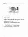
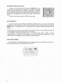
The Minolta Color Meter "IF helps to ensure consistent results when taking color photographs
using either ambient or flash ' light. It measures the light illuminat ing the subject and determines the
filtration required to reproduce subject colors correctly. Readings are provided for both light-balancing
filters (as required mired shift or Kodak Wratten filter numbers) and color-compensat ing filters (as
density). In addition, the photographic color temperature of the illumination can also be displayed .
The meter can be set to determine the required filters for any of three film types: Daylight (balanced
to 5500K), Type-A Tungsten (balanced to 3400K), or Type-B Tungsten (balanced to 3200K).
Either ambient or flash measurements can be taken. Ambient measurements can be taken under
illumination levels from EV3 to EV16.3 at ISO 100. Flash measurements can be taken for flash power
levels corresponding to apertures (at the meter position) of from f/2.8 to fI1BO (at ISO 100): they can
be taken with or without a sync cord, and shutter speeds from 1/500 to 1 sec. can be selected . For
flash measurements , the meter measures the mixed flash and ambient light , since this is what will
actually illuminate the subject , at the selected shutter speed . After measurement , the shutter speed
can be changed , effectively changing the ratio of flash to ambient light : by noting the change in
required filtration , you can predict the effect on the image color. In addition , the Color Meter IIiF can
subtract out the amb ient light to display the results for only the light from the flash.
To allow you to adjust the meter to your color preferences , correction values can be set in any of
the meter's nine memory channels . .Once these values havebeen set, the meter will automat ically
adjust measurement calculations to ensure that colors are reproduced according to your expectations .
Please take a moment to read this manual before using the Color Meter IIIF for the first time ,
and keep it handy for future reference.
STATEMENT OF FCC COMPLIANCE
This device complies with Part 15 of the FCC Rules. Operation is subject to the following two conditions :
(1) This device may not cause harmful interference, and (2) this device must accept any interference received ,
including interference that may cause undesired operation. Changes or modifications not approved by the
party responsible for compliance could void the user's author ity to operate the equipmen t. This equipment
has been tested and found to comply with the limits for a Class B digital device, pursuant to Part 15 of the
FCC Rules. These limits are designed to provide reasonable protection against harmful interference in a
residential installation . This equipment generates, uses and can radiate radio frequency energy and, if not
installed and used in accordance with the instructions, may cause harmful interference to radio commun ications .
However, there is no guarantee that interference will not occur in a particu lar installation. If this equipment
does cause harmful interference to radio or television reception , which can be determined by turning the
equipment off and on, the user is encouraged to try to correct the interference by one or more of the following
measures:
Reorient or relocated the receiving antenna.
Increase the separatio n between the equipment and receiver.
Connect the equipment into an outlet on a circuit different from that to which the receiver is connected . Consult
the dealer or an experienced radio/Tv techn ician for help.
STATEMENT OF DOC COMPLIANCE
This digital aparatus does not exceed the Class B limits for radio noise emissions from digital apparatus as set
out in the Radio Interference RegU lations of the Canadian Department of Communications.
NAMES OF PARTS
DATA PANEL
Over-lUnder-Range Indications
2
;
4
5
5
OVER/UNDER MEASURING RANGE
OVER/UNDER DISPLAY RANGE
6
6
6
Photograph ic Color Temperature , LB Index, or CC Index
LB Filter Number
PREPARATIONS
Power
7
7
INSTALLING BATTERIES
SWITCHING POWER ON AND OFF
AUTO POWER OFF
LOW·POWER WARNING
7
8
8
8
:.....
Setting Film-Type Switch
Selecting Display Mode
9
10
10
10
10
10
DISPLAY MODES
LB and CC Indexes
LB Filter Number and CC Index
Photographic Color Temperature
NOTES ON MEASUREMENTS ......... ........ ........................................... ....... .....
TAKING MEASUREMENTS
Ambient Light Measurements
Flash Measurements
WITH A SYNC CORD
WITHOUT A SYNC CORD
,
16
ANALYZE FUNCTION: MEASURING ONLY FLASH IN MIXED LIGHTING
USING MEMORY CHANNELS TO ADJUST METER READINGS
·
Selecting Memory Channel ..· ·
Setting Correction Values
ADDITIONAL INFORMATION
·..·..··
··..·..·
Obtaining Consistently Good Image Color
Filters
Photographic Color Temperature·
Problem Light Sources
11
13
13
14
14
·
·..·..·..·
18
19
19
·····20
·..···· ··· .. ·22
22
23
25
26
CARE AND STORAGE
27
BATTERY CAUTIONS
27
SPECIFICATIONS
28
r"'-l -
7
~::;;r.r.:::"':I1---8
~'!1I1 ~HI--- 9
3-----I::::~
4---I-~r£
~1+--- 1 0
+;1----11
5 - - -- ---'
6--------'
: ~1---- 1 2
~~'----- 1 3
2
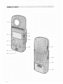
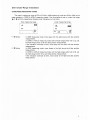
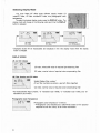
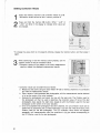
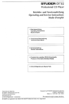
1 Receptor diffuser
2 Data panel
3 POWER button
Switches power on and off.
4 Memory channel (M-CH) button
When held pressed, allows memory channel to be selected using up/down control.
5 Memory (M) button
When held pressed , allows data in memory to be changed using up/down control.
6 Sync terminal
For connecting flash sync cord.
7 Measuring button
Takes measurements.
8 Measuring-mode switch
Selects measuring mode:
"AMBI" :
Ambient light measurements (see p. 13)
" CORD" : Flash measurements with a sync cord (see p. 14)
" NON.C" : Flash measurements without a sync cord (see p. 16)
9 Up/down control
• Adjusts shutter speed in " CORD" or "NON.C" measuring modes.
• Adjusts memory channel when used with memory channel button .
• Adjusts data in memory when used with memory button .
10 DISPLAY button
Changes display mode in the following order:
.. , -+ LB/CC indexes-+ LB filter number/CC index -+ Photographic color temperature-s
LB/CC lndexes-r ...
11 Flash-range switch
Selects measuring range for flash measurements:
Lo: f/2.8 to 22 (approx.)
Hi: f/22 (approx.) to 180
"The Lo and Hi ranges overlap by approximately 1EV.
12 Film-type switch
Selects film type :
B: Type-B tungsten film balanced for 3200K
A: Type-A tungsten film balanced for 3400K
0: Daylight film balanced for 5500K
13 Filter tables
14 Battery-chamber cover
3
2
1
TIME
aoS
ti
1.:1 1.:1 LJ
3
4
5
7
1
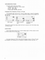
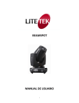
Display-mode indications
2
Measuring-mode indications
Indicate selected measuring mode.
3
"TIME" display (Not dlsptayedln "AMBI" measuring mode)
Indicates shutter speed for flash measurements in fractions of a second (for 1 second , value is
followed by " S" ); "F" indicates flash analyze function (see p. 18).
4
Measured valueslstored correction value
5
Memory-channel display (Not displayed if memory channel 0 selected)
Indicates selected memory channel.
6
Over-lUnder-range indications
m indicates measurement is over the measuring or display range.
l!J indicates measurement is under the measur ing or display range.
7
Flash-range indications (Not displayed in "AMBI " measuring mode)
Indicates selected flash measuring range.
4
Over-l Under-Range Indica tions
OVER/UNDER MEASURING RANGE
The meter 's measuring range is EV3 to EV16.3 in AMBI measuring mode and f/2.8 to f/180 (at the
meter position) in CORD or NON.C measuring mode. If the illuminance is over or under this range,
t!.l or l!J will blink respectively (Display-mode indications will not blink).
Over measuring range
LB
Under measuring range
LB
FILTER
cc
cc
TIME
• If t!.l blinks :
• If l!J blinks:
\ I I
3D
\
1.l!J,
Lo
In AMBI measuring mode, move away from the light source and take another
measurement.
In CORD or NON.C measuring mode with the flash-range switch set to La, set
the flash-range switch to Hi and take another measurement.
If the indication continues to blink , move away from the flash and take another
measurement.
In AMBI measuring mode, move closer to the light source and take another
measurement.
In CORD or NON.C measuring mode with the flash-range switch set to Hi, set
the flash-range switch to La and take another measurement.
If the indication continues to blink, move closer to the flash and take another
measurement.
5
OVER/UNDER DISPLAY RANGE
The meter 's display ranges are as follows :
Photographic color temperature: 1,600 to 40,OOOK
LB index: ·500 to +500
CC index : 200G to 200M
LB filter number: 80A+80D to 85B+81EF
Photographic Color Temperature, LB Index, or CC Index
If the calculated values would be over or under the display range or ranges for photographic
color temperature, LB index, and/or CC index , the display-mode indications will blink together with
either GJ or l!J .
LB/CC indexes
LB filter number/CC
index
Photographic color
temperature
• Measurements outside these display ranges would also be outside the more limited display range
for LB filter number.
LB Filter Number
If the calculated values would be over or under the display range for LB filter number, the value
for LB filter number will be as shown below.
In this case, although the LB filter number cannot be displayed, values for LB index , CC index,
and photographic color temperature can be displayed by changing the display mode (see p. 10).
6
Power
The Color Meter IIiF is powered by two AA-size 1.5V alkaline-manganese or carbonzinc, or 1.2V
nickel-cadmium batteries.
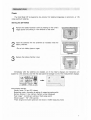
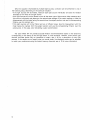
INSTALLING BATTERIES
1
Remove the battery-chamber cover by pressing on the cover's
ridged portion and sliding it in the direction of the arrow.
2
Insert the batteries with the polarities as indicated inside the
battery chambe r.
• Do not mix battery types or ages.
I
TI,-·_··..
.:st: l;. ..• ~~,- ~ ...., 11. '\''' ' ··•..
'' '''' ' ': _';,:'' j.
~ .l. :~ ~ :~':;:. : :~ ;_ .::-~3·~:,. :;,,;!.:: ·,·.~~~·:~ . ~ ~(~
,
, '[~~'21i
, ,
3
1'11· '
~.
.
-, .. ','o, -
. ~
(t/
Replace the battery-chamber cover.
Immediately after the batteries are installed, all of the meter 's displays and indications will
appear for a few seconds, and then the data panel will change to one of the measurement displays.
@ W~'; · + di l±t ·.· ¢' .< ' Fk ';':,i,j;ijC'
" I" ~T.E Rf L! L;.':H/?§? : mliIlJ .
~~:~~~,t,f~~~il!
Initial display settings:
Display mode: LB and CC indexes
Measuring mode: According to setting of measuring-mode switch
Memory channel : 0 (no memory channel number displayed)
Flash range *: According to setting of flash-range switch
Shutter speed *: " 60" (1 /60 second)
*Flash range and shutter speed are not shown in AMBI measuring mode.
7
SWITCHING POWER ON AND OFF
To switch on the Color Meter IIIF, press the POWER button; the
values for the last measurement will appear in the display. (If the setting
of the measuring-mode switch , or of the flash-range switch in CORD or
NON.C measuring mode, has been changed since the last measurement,
no values will be displayed.) The meter is then ready to take measure
ments.
To switch off the meter, press the POWER button again.
AUTO POWER OFF
To conserve power, the Color Meter IIIF automatically switches off if you do not take a measurement
or operate any of the switches or buttons for four minutes . To switch the meter back on, press the
POWER button. The display shown in the data panel just before the meter was switched off will
reappear.
• If the setting of the film-type switch is different from the setting when the meter automatically switched
off, the displayed values will be those for the new setting .
• If the setting of the measuring-mode switch, or of the flash-range switch in CORD or NON.C
measuring mode, is different from the setting when the meter automatically switched off, no data
will be shown in the data panel when the meter is switched back on.
LOW-POWER WARNING
When the power of the batteries becomes low, all displayed values and indications will blink. The
meter 's batteries should then be replaced with new ones.
\
I /
<,
I !
/
8
\
Setting Film-Type Switch
To obtain correct results , the film-type switch must be set to the
position corresponding to the film to be used.
B: Type-S tungsten films balanced for 3200K
A: Type-A tungsten films balanced for 3400K
0 : Daylight films balanced for 5500K
• If the setting of the film-type switch is changed after a measure
ment has been taken , the displayed values will be recalculated
for the new setting.
9
Selecting Display Mode
The Color Meter IIiF offers three different display modes: LB
index/CC index, LB filter number/CC index , and photographic color
temperatureo
To select the desired display mode, press the DISPLAY button. The
display mode will change in the following order each time the DISPLAY
button is pressed.
(},
i%.r;}id .~: . !.:....
LB index
CC index
,\\" ..-, .: '.
':':.
\
LB filter number
CC index
Photographic
color temperature
• Displayed values will be recalculated and displayed in the new display mode when the display
mode is changed.
DISPLAY MODES
LB and CC Indexes
LB index; mired shift value of required light-balancing filter
CC index; nominal value of required color-compensating filter
LB Filter Number and CC Index
Kodak Wratten filter number *
(If two filter numbers are shown, use both filters together)
CC index; nominal value of required color-compensating filter
* For Kodak Wratten filter numbers, lib " indicates B (as in 80B), lid" indicates 0 (as in 800) , and " E"
indicates EF (as in 81EF) .
Photographic Color Temperature
Photographic color temperature * in Kelvins
* Photographic color temperature is determined based on the spectral
response of color film. See p. 25 for further information.
10
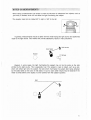
• When taking a measurement, be careful to avoid the influence of reflectance from objects, such as
your body or clothes, which will not affect the light illuminat ing the subject.
• The receptor head can be rotated 900 to right or 1800 to the left.
In general, measurements should be taken with the meter facing the light source and positioned
close to the light source. This method will provide satisfactory results in rnany situations.
f\
Light source
COlorMe~ U
Subject
o
~ ~came"
However, in some cases, the light illuminating the subject may not be the same as the light
emitted by the light source. This is especially true if the subject is near an object, such as a wall,
which will reflect light onto the subject; the light which illuminates the subject after being reflected
by the object takes on the color of that object. In such a case, better results may be obtained if the
meter is aimed either at the object or at the camera from the subject's position.
Wall
11
When the subject is illuminated by multiple light sources, correction can be performed in one of
the following ways, depending on the particular situation .
.. If the light sources will be filtered, measure each light source lndividually and add the filtration
indicated by the meter to the light source.
.
• If the light sources will not be filtered but are all the same type of light source, either measure each
light source individually and determine the approximate average of the meter readings, or take the
measurement with the meter facing the camera from the subject position, and use the corresponding
filtration over the camera lens.
• If the light sources will not be filtered and are of different types, take the measurement with ,the
meter facing the camera from the subject position and use the corresponding filtration over the
camera lens. In this case, color bracketing ;s also recommended.
The Color Meter IIiF will provide accurate filtration recommendations based on the sensitivity
corresponding to the setting of the film-type switch in most situations. However, under certain light
sources, accurate results may be impossible to obtain; see p. 26 for a description of such light
sources. If the results are not exactly what you would prefer, the displayed values can be adjusted
to match your preferences using the meter's memory channels; see p. 19 for more information.
12
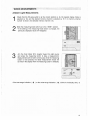
Ambient Light Measurements
1
Check that the film-type switch is at the correct position (p. 9), the desired display mode is
selected (p. 10), and the desired memory channel is selected (p. 19; if no memory channel
number is shown, the selected memory channel is 0).
2
Slide the measuring-mode switch up to the "AMSI" position.
• If the setting of the measuring-mode switch is changed , the
previously displayed values will disappear.
3
Aim the Color Meter IIIF's receptor toward the light source
and press the measuring button to take a measurement.
Measurements will be taken continuously while the measuring
button is held pressed; the latest measurement results will
be held in the display when the measuring button is released.
• If the over-range indication ( l!) ) or the under-range indication ( l!J ) blinks in the display, see p. 5.
13
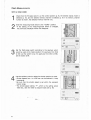
Flash Measurements
WITH A SYNC CORD
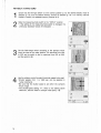
1
2
Check that the film-type switch is at the correct position (p. 9), the desired display mode is
selected (p, 10), and the desired memory channel is selected (p. 19; if no memory channel
number is shown , the selected memory channel is 0).
Slide the measuring -mode switch to the "CORD" position .
• If the setting of the measuring-mode switch is changed,
the previously displayed values will disappear.
3
Set the flash -range switch according to the aperture which
would be used at the meter position : For apertures from f/2.8
to f/22, set the switch to La; for apertures from f/22 to f/180,
set the switch to Hi.
4
Use the up/down control to select the shutter speed to be used.
• Shutter speeds from 1 to 1/500 sec, can be selected in t -stop
increments.
• Be sure that the shutter speed is set within the camera's
X-sync range,
• The shutter-speed setting " F", which is the setting above
1/500 sec., sets the meter to analyze mode (see p. 18).
-
14
... ..
,..
.,
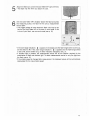
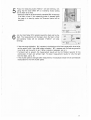
5
Attach the flash sync cord to the Color Meter IIIF's sync terminal.
• The flash may fire when you attach the cord .
6
Aim the Color Meter IIIF's receptor toward the flash and press
the measuring button; the flash will fire and a measurement
will be taken.
• The trigger voltage of some electronic flash units may be too
low for the Color Meter IIIF to fire them in cord mode. If this
is true of your flash , use non-cord mode (see p. 16).
m)
appears in the display and the flash-range switch is set to La,
• If the over-range indication (
set the switch to Hi. If the under range indication ( l!J ) appears and the flash-range switch
is set to Hi, set the switch to La. If either indication reappears, see p. 5.
• If ambient light is present, the measurement results will be the filtration required for the
combination of flash and ambient light. To obtain measurement results for only the light from
the flash, see p. 18.
• If the shutter speed is changed after measurement, the displayed values will be automatically
recalculated for the new shutter speed.
15
WITHOUT A SYNC CORD
1
Check that the film-type switch is at the correct position (p. 9), the desired display mode is
selected (p. 10), and the desired memory channel is selected (p. 19; if no memory channel
number is shown, the selected memory channel is 0).
2
Slide the measuring-mode switch to the "NON.C" position.
• If the setting of the measuring-mode switch is changed , the
previously displayed values will disappear. ""
3
Set the flash-range switch according to the aperture which
would be used at the meter position: For apertures from f/2.8
to f/22 , set the switch to Lo; for apertures from f/22 to f/180,
set the switch to Hi.
4
Use the up/down control to select the shutter speed to be used.
• Shutter speeds from 1 to 11500 sec. can be selected in
t-stop increments.
• Be sure that the shutter speed is set within the camera's
X-sync range.
• The shutter-speed setting " F", which is the setting above
1/500 sec., sets the meter to analyze mode (see p. 18).
16
5
Press the measuring button."NON .C" will start blinking, indi
cating that the Color Meter "IF is in stand-by mode, waiting
for the flash to be fired.
,.
• Stand-by mode will be automatically canceled after 16 seconds
if no flash is fired. If the measuring button is pressed while
the meter is in stand-by mode, the 16-second period will be
restarted.
I
6
Aim the Color Meter "IF's receptor toward the flash and fire the
flash. The measurement will be taken when the flash is fired
and stand-by mode will be canceled ("NON.C" will stop
blinking) .
'.
<.
·:SI~ c\
i'
;'co
S
;:" ,';" :..•
,. . .
. ,.0' ;;
/"'f
')
~o
m)
• If the over-range indication (
appears in the display and the flash-range switch is set to Lo,
set the switch to Hi. If the under range indication ( I!J ) appears and the flash-range switch
is set to Hi, set the switch to Lo. If either indication reappears, see p. 5.
• If ambient light is present , the measurement results will be the filtration required for the
combinat ion of flash and ambient light. To obtain measurement results for only the light
from the flash, see p. 18.
• If the shutter speed is changed after measurement , the displayed values will be automat ically
recalculated for the new shutter speed.
17
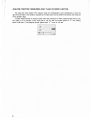
ANALYZE FUNCTION: MEASURING ONLY FLASH IN MIXED LIGHTING
By using the Color Meter IIIF's analyze mode, the photographic color temperature of only the
light from the flash or the filtration required for the flash alone can be determined without the influence
of the ambient light.
To take measurements in analyze mode, follow the procedure for flash measurements with a sync
cord (see p. 14) or without a sync cord (see p. 16), but set the shutter speed to " F" (the setting
above 1/500 sec.), The effective shutter speed when "F" is set is 1/15 sec.
18
The filtration values determined by the Color Meter IIIF are intended to be suitable for as wide a
variety of films as possible. However, photographs taken using the unadjusted meter readings may
not reproduce scene colors exactly as they are or as you would prefer. The Color Meter "IF has nine
memory channels in which you can store values to adjust the meter readings to your preferences.
Correction values for LB index and CC index can be input separately, and the stored correction
values are used for all film-type settings.
• The Color Meter IIIF has ten memory channels in total; however, values in memory channel
cannot be changed .
• Correction values in all channels are set to 0 at the time of shipment.
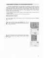
a
Selecting Memory Channel
1
2
3
Set the display mode to LB/CC indexes or LB filter number/CC index by pressing the DISPLAY
button (p.10) .
Press and hold the memory-channel (M-CH) button. "CH" will
blink in the display and the presently selected memory channel
number will be shown.
While continuing to hold the memory-channel button pressed,
use the up/down control to select the desired memory channel
number.
19
Setting Correction Values
1
Select the memory channel to set correction values in (p.19) .
• Correction values cannot be set in memory channel O.
2
Press and hold the memory (M) button. Either " 11 LB" or
" 11 CC" will blink in the display to indicate which value can
be changed.
)'iF
'f
'~
.\\i\
..;C,
,<
<;
.b "
~10'1
i\ "
.
,;:''' ..
.., 'y \ '': ,;
• To change the value which is not presently blinking , release the memory button , and then press it
again.
3
While continuing to hold the memory button pressed, use the
up/down control to set the correction value.
• Correction values will be added to the initial measurement
results to obtain the displayed measurement results.
>'A
. ~,
·ff.!
..~ ~
......
l~.
;': <i ,'"
. \ . .,~.
h \'·'
• Correction values can be determined as follows:
a Measure a test scene using the Color Meter "IF set to memory channel 0 (no correction)
and note the measurement results.
b Take a series of color-bracketed test photographs, with the measurement results obtained
in (a) as the center of the color brackets.
c Evaluate the photographs and select the one with the best color. The filtration used for
this photograph will then be used to determine the correction value. (If none of the test
photographs have exactly the right color, repeat (b) with the filtration used for the best
photograph as the center of the color bracket.)
d Once an acceptable test photograph has been obtained , the LB correction value can be
determined by subtracting the LB index measured in (a) from the mired shift value of the
filtration used for the test photograph. The CC correction value should be adjusted
repeatedly until measurements under the conditions in (a) give values corresponding to
the CC filtration used for the test photograph.
20
4
Repeat steps 2 and 3 if necessary to set the other correction value for the selected memory
channel.
• The meter's case has a memo holder in which you can put a card listing the correction values in
each memory channel or what conditions (film type, light source, etc.) each channel has been
set for.
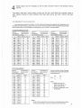
FOR OWNE RS O F THE CO LOR METER II
If yo u ha ve b een using th e C olor Meter II's VAR I. se tti ng and se tting a p ho to graphic c olor temperature , you
c an ach ieve the sa m e effect by usi ng the me moryfuncti ons of th e Color Mete r IIIF and inp utti ng the AL B correction
value co rrespo nd ing to the ph oto graph ic temperat ure you se t, as list ed in the tab les below.
Fo r film -t:li12 e sett ings A an d B',
Desired
Corresponding
photographic
t. LB correction
color temperatur e value
Desired
Corresponding
photographic
t.L B correction
color temperature value
Desired
Corresponding
photograp hic
t.L B correction
color temp erature value
Type B Type A
K
Mired
K
Mired
K
Mired
2800
2820
2840
2860
2880
357,14
354,61
352,1 1
349,65
347.22
+45
+42
+40
+37
+35
+63
+60
+58
+56
+53
3200
3220
3240
3260
3280
312,50
310.56
308,64
306.75
304,88
0
-2
·4
-6
-8
+18
+16
+15
+13
+11
3600
3620
3640
3660
3680
277.78
276.24
274.73
273,22
271.74
-35
-36
-38
-39
-41
-16
-18
-19
-21
-22
2900
2920
2940
2960
2980
344.83
342.47
340.14
337,84
335,57
+32
+30
+28
+25
+23
+51
+48
+46
+44
+4 1
3300
3320
3340
3360
3380
303,03
301.20
299.40
297,62
295,86
-9
-11
-13
·15
·17
+9
+7
+5
+4
+2
3700
3720
3740
3760
3780
270.27
268,82
267,38
265.96
264,55
-42
-44
·45
-47
-48
-24
-25
-27
-28
·30
3000
3020
3040
3060
3080
333 ,33
331.13
328,95
326,80
324.68
+21
+19
+16
+14
+12
+39
+37
+35
+33
+31
3400
3420
3440
3460
3480
294,12
292.40
290,70
289.02
287,36
-18
-20
-22
-23
-25
0
·2
-3
-5
-7
3800
3820
3840
3860
3880
263,16
261.78
260.42
259.07
257,73
-49
-51
·52
-53
-55
-31
-32
·34
-35
·36
3100
3120
3140
3160
3180
322.58
320.51
318.47
316.46
314.17
+10
+8
+6
+4
+2
+28
+26
+24
3500
3520
3540
3560
3580
285.71
284,09
282.49
280.90
279,33
-27
-28
-30
-32
-33
-8
-10
-12
-13
-15
3900
3920
3940
3960
3980
256.41
255,10
253.81
252.53
251.26
·56
·57
-59
-60
-61
-38
-39
-40
·42
·43
Typ e B Typ e A
For fi lm-t:li12e setting
-t: 22
+20
Type B Type A
p;
Desired
Corresponding
photographic
t.L B correction
color temperature value
Desired
Corresponding
photographic
t. LB correction
color tempe rature value
K
Mired
Type 0
+18
+16
+14
+12
+10
6000
6050
6100
6150
6200
166,67
165,29
163.93
162,60
161,29
-15
-17
-18
-19
-21
190.48
188.68
186.92
185.19
183.49
+9
+7
+5
+3
+2
6250
6300
6350
6400
6500
160,00
158,73
157.48
156.25
153,85
-22
-23
-24
-26
·28
5500
5550
5600
5650
5700
181,82
180.18
178.57
176,99
175.43
0
-2
-3
-5
-6
6600
6700
6800
6900
7000
151.52
149.25
147,06
144,93
142,86
-30
-33
-35
-37
·39
5750
5800
5850
5900
5950
173.91
172.41
170,94
169.49
168,07
-8
-9
-11
-12
-14
NOTE;
K
Mired
5000
5050
5100
5150
5200
200,00
198,02
196,08
194,17
192,31
5250
5300
5350
5400
5450
Type D
Values not listed in either of the sets
of tab les can be calculated us ing the
foll owi ng equation :
10 6
10 6
T2
T1
AL B= -
w here :
T 1=5500 K (Film type D),
34 00K (Fil m type A ), or
320 0K (Film type B)
T 2=D esire d photograph ic co lo r
tempe rat ure
Some furt her ad jus tm en ts f rom the listed or cal cul ated v alues may be
nec essary depe nd ing on t he exact sens itiv ity of the mete r cel ls.
21
Obtaining Consistently Good Image Color
A color image and how it is perceived by the viewer is the final result of the interaction of various
factors, including film, lighting conditions, processing , and viewing conditions. These factors can be
considered as the parts of an overall system; to obtain consistently good image color, all parts of the
system must be kept consistent. To do this, follow the steps below.
Purchase a quantity of film from the same emulsion batch and store the film under optimum
conditions until use.
2
Find a high-quality processing lab that produces consistent results and use only this lab for
processing .
3
Balance your viewing system to photographic daylight (5500K) and check it periodically.
• Because the spectral sensitivity of the Color Meter "IF corresponds to the sensitivity of photo
graphic film and not to the spectral sensitivity of the eyes, it is not recommended for use in
balancing your viewing system. For such purpose, a colorimeter with spectral sensitivity closely
matching that of the eyes (such as the Minolta Chroma Meter CL-100) should be used. Further,
since photographic color temperature alone is insufficient to exactly specify a color, it is recom
mended that the viewing system be balanced using the x and y chromaticity coordinates of the
standard illuminant corresponding to 5500K. These coordinates are 0.332, 0.348.
The above three steps, together with using the Color Meter "IF to control the color of the lighting,
will provide consistent results. However, the resulting color may be somewhat different from the color
results you would like. If this is the case, the system should be fine-tuned by adjusting the correction
values in the memory channels of the Color Meter IIIF according to the procedure on p. 19.
22
Filters
The Color Meter IIIF provides readings for two types of filters: LB (light-balancing) filters and
CC (color-compensating) filters. '
Light-balancing filters are used to increase or reduce the color temperature of light. The amount
by which the filter changes the color temperature is usually specified as the mired (micro-reciprocal
degree) shift of the filter. The LB index provided by the Color Meter IIIF is the mired shift value of
the required filter. Positive (+ ) mired shifts decrease the color temperature of the light, making it
more yellow; negative (-) mired shifts increase the color temperature, making it more blue.
The filter corresponding to a displayed LB index can be found by referring to the table on the
back of the Color Meter IIIF, which lists Kodak Wratten filters corresponding to LB index values, or
to a chart included with filters. Remember that filters can be combined if necessary to obtain the
required mired shift. For example, for an LB index of +149, you could use an 85B filter (mired shift
value: +131) together with an 81A filter (mired shift value: + 18).
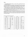
The Color Meter IIiF can also provide direct readout of Kodak Wratten filter numbers, for both
light-balancing (81 and 82 series) and conversion (80 and 85 series) filters. The 81 and 82 series
Kodak filters provide minor shifts in color temperature; the 80 and 85 series provide much larger
shifts. When more than one filter must be used to obtain the required mired shift , the Color Meter
IIIF displays both filter numbers. The table below shows the relation between the LB index and the
LB filter number displayed.
LB Index and Corresponding LB Filter Number
L8 index
Filter number
< -193
---192 to -182
80A + 800
-181 to -170
80A + 82C
-169 to -158
80A + 828
-157 to -147
80A + 82A
-146 to -137
80A + 82
-136 to -127
80A
-126 to ·1 18
808 + 82
-117 to -108
808
-107 to
-97
80C + 82A
-96
to
-87
80C + 82
-86
-80
to
80C
-79
-72
800 + 82A
to
-71
-62
800 + 82
to
-61
to
-51
800
-50
-39
to
82C
-38
-27
to
828
-26
to
-16
82A
-15
to
-6
22
+ 4 """' ~' r~:: O · , ,.•
-5
to
+5
to
+13
81
I
I
,
I
L8 index
+14 to
+22
+30
+ 23 to
+38
+31
to
+39 to
+ 46
+47 to
+56
+65
+ 57 to
+66 to
+75
to
+76
+85
+86 to
+94
+95 to + 103
+ 104 to + 109
+ 110 to + 116
+ 117 to + 125
+ 126 to + 135
+ 136 to + 144
+ 145 to + 153
+ 154 to + 161
+ 162 to + 169
+ 170 to + 177
+ 17~ to + 188
> + 189
I
I
Filter
81A
818
81C
810
81EF
81EF
81EF
85C
85C
85C
85C
85
85
858
858
858
858
858
858
858
number
+
+
81
81A
+
+
+
81
81A
818
+
81
+
+
+
+
+
+
81
81A
818
81C
810
81EF
I
I
---
23
Color-compensating filters adjust the quantity of only a single quantity of light, such as red, blue,
or green. The CC index provided by the Color Meter IIIF indicates the nominal density of the green
(G) or magenta (M) CC filter required. Both of these filters adjust the quantity of green in the
illumination; since magenta is the complementary color of green, it can be thought of as " minus
green". Indications for other CC filters are unnecessary, since the light-balanc ing filters adjust the
quantities of red and blue in the illumination . CC filters are specified by their nominal density ; for
example, a CC05G filter would be a green filter with a nominal density of 0.05.
J
.
Filters can be placed either in front of the light source, or behind or in front of the camera lens.
Light-source filters affect only the light from the source they're placed in front of; thus , they can
be used to balance the light from several sources to a single value. In addition , since they are not
in the optical path between the subject and the film , they do not affect the image quality at all; also,
exposure compensat ion is not necessary, even when using a handheld meter. However, they can
be tedious to work with when using multiple light sources; in addition, the range of filters available
is not as wide as that of lens filters.
Lens filters may be somewhat easier to use. However, since they are between the subject and .
the film, they must be of higher optical quality. All lens filters must be handled carefully and kept
clean, since scratches, fingerprints , dust, etc. on the filter will degrade the image. In addition , the
color dye in lens filters may reduce the image sharpness , especially for filters with high density ; for
this reason, combining more than two or three lens filters is usually not recommended. Lens filters
affect the overall color of the entire scene; when several sources are used, a compromise filtrat ion
pack must be determined if the color output by all sources is not the same.
Exposure compensation must also be considered when using lens filters. If exposure is determined
using a handheld meter, the exposure compensation for the lens filter or filters being used must be
calculated and the exposure adjusted accordingly; when using a camera's TTL (through-the-Iens)
meter, this is not necessary. Exposure compensation is usually listed in the literature accompanying
the filter ; the table on the back of the Color Meter IIIF also lists compensation (+EV) values for LB
and CC filters. When using more than one filter, the required exposure compensation is the sum of
the compensations for each , filter. For example, when using an 82B filter (compensation: +2/3EV)
together with a CC10M filter (compensation: + 1/3EV), the total required exposure compensation
would be +1EV.
Occasionally, both light-source and lens filters must be used together. This is particularly true
when using different types of light sources. In this case, light-source filters are used to balance all
of the light sources to a single value; lens filters are then used to correct that value for the film
being used .
24
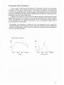
Photographi c Color Temperature
The Color Meter IIIF determines the photograph ic color temperature according to the ratio between
the intensity of light in the blue region and that in the red region of the spectrum; the resulting value
is referred to as "photographic color temperature ", since it is determined based on the characteristics
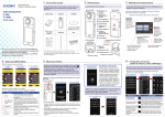
of color film . Higher BIR ratios result in higher photographic color temperatures. However, this method
assumes that the spectral power distribution of the light source is continuous with no sharp peaks, such
as those of sunlight and many tungsten lamps.
Although the Color Meter IIIF can provide color-temperature readings for light sources with spectral
power distributions which are not continuous or which contain sharp peaks (such as those of fluorescent
lamps) , such readings will not necessarily be accurate and may not provide an accurate indication
of how photographic film will respond to such sources. Thus, color-temperature measurements of
such sources are not recommended .
• "Photographic color temperature" is different than the " color temperature" used in physics and
colorimetry. Basically, color temperature as used in physics and colorimetry refers to the temperature
at which an ideal blackbody would emit light of the same color (having the same chromaticity) as
that of the light being measured.
Spectral power distribut ions
%
%
100
100
50
50
400
500
600
Sunlight
700 (nm)
40 0
500
600
700 (nm)
Fluorescent lamp
25
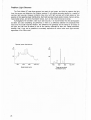
Problem Light Sources
The Color Meter I/IF uses three sensors (one each for red, green, and blue) to measure the light
from the source and determine the filtration required. It will provide accurate results for a variety of
common light sources. However, problems may occur with light sources with sharp peaks (or line
spectra) in their spectral power distributions . Such light sources include sodium lamps, mercury lamps,
metal-halide lamps, and some fluorescent lamps, such as the three-narrow-band lamps.
If photographs will be taken under such light sources, it is recommended that test photographs
be taken and color bracketing be performed. If there is a difference between the displayed filter
value and the actual required filtration , this difference will generally be the same for all lamps of
this type, and can thus be stored in one of the memory channels for later use. Please remember,
however, that it may not be possible to accurately reproduce all colors under such light sources,
regardless of the filters used,
Spectral power distributions
%
%
100
100
50
50
400
500
600
Metal-halide lamp
26
700
(nm)
700 (nm)
Three-narrow-band
fluorescent lamp
• Do not press on or damage the data panel.
• Do not subject the meter to shock or vibration.
• This meter should be used at temperatu res between -10 and 50°C (14 and 122°F).
Operation at temperatures outside this range may be unsatisfactory.
• This meter should never be placed or left in the glove compartment or other places in a motor
vehicle, or in other locations where it may be subject to temperatures higher than 55°C (131°F) or
lower than -20°C (-4°F), as it may be permanently damaged. Particular care should be taken not
to leave the meter in direct sunlight or near sources of heat such as strong lights, etc. Do not store
this meter in humid places or near corrosive chem icals.
• If the meter is left or placed in direct sunlight for any long period , the data panel may turn black .
• When the meter is to be stored, place it in its original packing and put it in an airtight container
with an appropriate amount of dehumidifying agent , such as silica gel.
• Never attempt to disassemble the meter. Any necessary repairs should be performed only by an
authorized Minolta service facility.
• The meter body may be wiped with a silicone-treated cloth to clean it. Do not allow alcohol or
chemicals of any -other kind to touch its surface .
• Never lubricate any part of the meter.
Improper handl ing of batteries may result in explosion , burn, or heat generation.
• Do not attempt to disassemble, recharge, or short out the battery, or subject it to high temperatures
or fire.
• Never use batteries that show signs of leaking or cracking .
• When inserting batteries, make sure the + and - terminals face in the correct direction.
• Don't mix batteries of different types, ages or brands.
• For extended storage, remove the batteries. Otherwise, leaking or gas generation may occur.
• Read and follow all warningas and instruct ions supplied by the battery manufacturer.
27
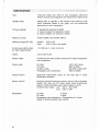
Type:
Three-color digital color meter for color photograph; determ ines
filtration required and photographic color temperature of light sources
Receptor head:
Rotating (900 to right/1800 to left) receptor head containing three
silicon photocells (filtered to red, green, and blue sensit ivities
appropriate for color photography)
Film-type settings :
D: Daylight film balanced to 5500K
A: Type-A Tungsten film balanced to 3400K
B: Type-B Tungsten film balanced to 3200K
Measuring modes :
Ambient (AMBI); flash (CORD, NON.C)
Measuring range (ISO 100):
Ambient:
Flash:
Shutter-speed setting range
(for flash measurements):
1 to 1/500 sec. in t-stop increments
Display:
Liquid crystal (LCD)
Display modes :
LB index and CC index ; LB filter number and CC index ; photographic
color temperature
EV3 to 16.3
f/2.8 to 180 (in two ranges)
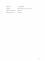
Display range:
LB index:
CC index:
.LB filter number :
Photographic color temperature :
Analyze function :
Determines measurement values for only flash light in mixed
flash/ambient situations
Memory function :
9 memory channels for storing correction values to adjust calculated
filtration (LB index and CC index); stored values automat ically
added to initially calculated values before display of results
Correction-value range: L. LB: -100 to + 100 mireds
L. CC: 100G to 100M
Repeatability:
LB index:
2 mireds
CC index:
2 digits
Photographic color temperature: Corresponding to 2 mireds
(Based on Minolta's standard test method)
28
-500 to 500 mireds
200G to.2 00M
80A+80D to 85B+81EF
1600 to 40,000K
Power source:
2 AA-size batteries
Dimensions:
160 x 68 x 28mm (6-1/4 x 2-11/16 x 1-1/8 in.)
Weight (without batteries):
2009 (7.1 oz.)
Standard accessories:
Case; strap
29
~
•
•1
~
MINOLTA
© 1992 Minolta Co., Ltd. under the Berne Convent ion
9222-8055-18
and Universal Copyright Convention
ABFBP@ Printed in Japan