1
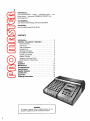
Model 700
Power Console
Instruction
.
The Features..
you find most useful.. .stereo.. . pre-fader monitor.. .two
power amps.. . exclusive FEEDBACK FINDER'" and
PATCH BLOCK'"
The Reliability...
you need for demanding, continuous operation
The Quality.. .
you've come to expect from Shure
CONTENTS
Introduction . . . . . . . . . . . . . . . . . . . . . . . . . . . ..
.. . . . . 3
Controls Connectors Indicators . . . . . . . . . . . . . . . 4
Input Channels . . . . . . . . . . . . . . . . . . . . . . . . . . . . . . . . 4
Aux Inputs . . . . . . . . . . . . . . . . . . . . . . . . . . . . . . . . . . . .5
Status Indicators. . . . . . . . . . . . . . . . . . . . . . . . . . . . . . . 5
Headphones
5
DB Peak Indicators. . . . . . . . . . . . . . . . . . . . . . . . . . . . . 6
FEEDBACK FINDER'" . . . . . . . . . . . . . . . . . . . . . . . . . .6
Graphic Equalizers . . . . . . . . . . . . . . . . . . . . . . . . . . . .6
Master Controls . . . . . . . . . . . . . . . . . . . . . . . . . . . . . . . 7
Speaker and Power Panel . . . . . . . . . . . . . . . . . . . . . . . 8
PATCH BLOCKTM
Rear Panel . . . . . . . . . . . . . . . . . . . . 9
Setups . . . . . . . . . . . . . . . . . . . . . . . . . . . . . . . . . . . . . . . .. l l
.
Operation . . . . . . . . . . . . . . . . . . . . . . . . . . . . . . . . . . . . .14
. . . . . . . . . . . . . . . . . . .14
Maintenance . . . . . . . . . . . . . . .
.
Troubleshooting . . . . . . . . . . . . . . . . . . . . . . . . . . . . . . ..15
Specifications . . . . . . . . . . . . . . . . . . . . .
.
. . . . . . . . . . .16
.
Speaker Systems . . . . . . . . . . . . . . . . . . . . . . . . . . . . . .17
.
Accessories . . . . . . . . . . . . . . . . . . . . . . . . . . . . . . . . . . .18
.
Guarantee . . . . . . . . . . . . . . . . . . . . . . . . . . . . . . . . . . . . .18
Shipping Instructions . . . . . . . . . .
WARNING
To prevent a source of fire or electric shock, do not
expose this appliance to rain or extreme moisture.
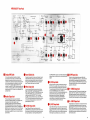
hboducing the Shure
Power Console Mod4 700
PRO MfiST€RTM
. . . a portable, high-power, stereo, 8-input
mixer-amplifier with the flexibility and dependability
demanded by professional entertainers and sound
system operators. The result of years of design
concept study and evaluation, the PRO MASTER
handles any sound job well-even those grueling
tours where daily setups and "knockdowns" punish
equipment severely.
The PRO MASTER is an all solid-state unit,
employing the latest developments in highly reliable
integrated circuit, discrete component, and printed
wiring technology. It's easy to set up and operateno separate power amps, equalizers or reverb are
required. And connecting accessory equipment is
fast and convenient.
The PRO MASTER is full of features for super
performance and super convenience-the unique
FEEDBACK FINDER'" helps maximize gain before
feedback, makes feedback location and
suppression fast and easy. . . exclusive PATCH
BLOCK'" rear panel shows you where you're
patching, helps you construct complex circuits
using simple patch cords. . . efficient "wind tunnel"
power amp design has temperature warning and
shutdown LED indicators.
Its versatile control panel is human-engineered for
ease of operation in daylight or the darkest,
smoke-filled clubs. And it's packaged in a
handsome, rugged, lightweight, molded
ARMO-DUR'" case complete with carrying handle
and line cord storage.
The PRO MASTER offers you the best of all worldsquality sound for small, intimate clubs, churches and
schools, or large auditoriums. In combination with
Shure's PRO MASTER Speaker Systems, you've got
a sound reinforcement system that's ideal for every
application. Need more capability? The PRO
MASTER is super-expandable-use accessory
mixers or power amps, stage monitor speakers,
effects devices, whatever you need can easily be
added. And it's all backed by Shure's traditional
quality and reliability. It's the sound you need . . .
when you need i t . . . and where you need it.
Just look at these features-
* Completely stereo
Twin full 200-watt power amplifiers
Six high-impedance and six balanced
low-impedance mic inputs plus two aux inputs
plus A/B EQ and PA (power amp) inputs
Six input channels for microphones and aux level
sources with full controls: volume, attenuation, A/B
pan, frequency equalization, effectsireverb, and
monitor
High- and low-impedance inputs may be used
simultaneously
Two additional aux channels with volume and AIB
pan controls
Full master controls: monitor, A volume, B volume,
effects send, reverb return, and reverb high- and
low-frequency equalization
Outputs for all needs: monitor, effects, stereo
headphones, A+B aux, A+B mic, and A and B
speakers (2 each)
Four common mix buses: A and B mix output, and
A and B equalizer output
Balanced mono (A+B sum) mic output for "house"
systems
Record in stereo with mono performance and
separate mono stage monitor
Unique FEEDBACK FINDER with LED readout
instantly identifies feedback frequency bands
Twin 10-band graphic equalizers with minimum
phase, combining-type filters. Lowest filter is
-12 dB1octave cut-only switch; others are
2 13 dB adjustable
Exclusive PATCH BLOCK rear panel shows you
where to patch-jacks are located right in the
block diagram
Built-in reverb unit with provisions for external
onloff switching and external effects devices
Regulated 24 Vdc simplex supply for powering
condenser microphones
Bright red LED indicators show input clipping,
power amp peak output level, power amp
overload, power-on, temperature warning, and
shutdown
Protected against damage from open- or
short-circuits on inputs or outputs
Protected against heat damage by ultra-reliable
cooling fan and automatic thermal shutdown
circuit
Protected against radio frequency interference
and line noise
Operates on as low as 100 Vac (at reduced output)
Rugged molded ARMO-DUR case with carrying
handle and line cord storage
Listed by Underwriters' Laboratories, Inc.; listed
by Canadian Standards Association as certified
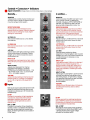
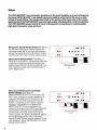
Controls Connectors Indicators
Input Channels
:ate basic or lnit~alsettings)
(Orange marks on controls ind~c
...
.
Basically
In addition..
MONITOR
Independently controls channel monitor level
to monitor output. Adjust for desired monitor
mix when using a monitor system.
MONITOR
Control precedes VOLUME ("pre-fader") and
other channel controls; not affected by
VOLUME, EQualizers, EFFECTSIREVERB,or
N B PAN. Only affected by INPUT ATTEN,
allowing totally independent monitor mix.
EFFECTSIREVERB
Controls amount of reverberation and/or
external effects on channel. Adjust for desired
amount (use low settings for vocals, higher
settings for instruments).
EFFECTSIREVERB
This channel send control follows the INPUT
ATTEN, VOLUME and EQ controls. Can be
used simultaneously with reverb and external
effects devices, or as a second monitor
("post-fader")to the EFFECTS OUTPUT jack.
HI FREQ EQ
Sets channel treble boost or cut for desired
tone shaping.
HI FREQ EQ
Adjusts channel r 13 dB at 10 kHz on A and B
outputs and effects output; does not affect
monitor output.
LO FREQ EQ
Sets channel bass boost or cut for desired
tone shaping.
LO FREQ EQ
Adjusts channel r 13 dB at 100 Hz on A and B
outputs and effects output; does not affect
monitor output.
AIB PAN
Used for stereo (left-right) positioning in stereo
sound reinforcement or recording. Position
straight up for center (monophonic) sound
reinforcement use.
AIB PAN
Used for stereo positioning; allows
assignment of channel signal to both A and B
(straight up) or only A or B output channel (full
counterclockwise or clockwise), or any
position between.
INPUT CLlP
Indicates when input signal is too high. Adjust
INPUT ATTEN until only occasional flashes are
noted.
INPUT ATTEN
Adjusts input attenuation for channel.
Suggested initial settings: condenser
microphones or amplified instruments -12 to
- 30; normal vocals - 6 to - 12; loud vocals
-12 to -24; distant miking 0.
VOLUME
Allows individual setting of channel input for
desired signal mix. If setting is consistently
low (1 or 2), or high (8 to lo), adjust INPUT
ATTEN.
Both inputs may be used at the same time with
similar microphones (one high and one low
impedance),allowing up to 12 microphones
simultaneously.
HI IMP
Provides for connection of high-impedance
microphones, direct instrument pickups,
keyboards, amplified instruments, tape
recorders or other high-level sources to
channel input.
BAL LO IMP
Provides for connection of low-impedance
dynamic, ribbon or condenser microphones
and other low-level inputs to channel input.
(Don't use when high-level source is used on
HI IMP input.)
INPUT CLlP
Lights approximately 3 dB prior to clipping of
preamp or input channel equalizer. For
optimum signal-to-noise ratio, adjust INPUT
ATTEN for occasional flashes (no light may
mean noisy operation; constant light means
distortion).
INPUT ATTEN
Adjusts gain of preamplifier to permit channel
to accept microphone level signals, direct
instrument pickups, or high level aux signals
from amplified instruments or tape recorders;
almost any input device can be
accommodated.
VOLUME
Affects all A and B outputs plus A+B outputs
and effectslreverb level; does not affect
monitor mix.
HI IMP
Can be used with line matching transformer
(Shure A95FP) to allow two low-impedance
microphones on channel (not recommended
for two condenser microphones).
BAL LO IMP
Also may be used to power most condenser
microphones such as the Shure SM81; built-in
+24 Vdc simplex power supply voltage
activated by rear-panel switch.
Pux Inputs
Channels 7 and 8 are aux level inputs, providing additional input
capabilities for tape recorders, synthesizers, amplified instruments,
background music sources, preamplified phonographs, or other mixers.
These channels have AiB PAN controls for stereo positioning, VOLUME
controls for setting the channel input mix level, and AUX INPUT phone
jacks. To play a stereo tape, connect the left tape channel to AUX INPUT 7
and set the channel 7 PAN control to A (full counterclockwise). Connect
the right tape channel to AUX INPUT 8 and set the channel 8 PAN control
to B (full clockwise). If equalization, reverbleffects and monitor are
desired, use two of the first six input channels with proper input
attenuation.
These inputs can also be used for the return signal from an external effects
device (delay, echo, etc.) driven by the EFFECTS OUTPUT.
When an additional mixer (such as the Shure M68, M67 or SR101) is
connected to channel 7 or 8, the aux channel volume control becomes a
submaster control.
The orange control marks indicate basic or initial settings.
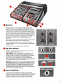
LCD Status lndicotors
POWER-Indicates application of ac voltage to power supply when
rear-panel ON-OFF switch is turned on.
TEMP WARNING-Lights when unusually high temperature of 70°C
(158°F) is reached on the output transistors. Indication may be due to
blockage of air louvers, dirty air filter, or operating the console at a high
output level with a low load impedance (too many speakers or a
short-circuited output). Indicator will turn off when transistor case
temperature drops below 70°C. If indicator lights, it is advisable to identify
the cause and make corrections to avoid shutdown.
SHUTDOWN-When indicator is on, both power amplifiers are turned off
(all other circuits remain on). The console may shut down for one of the
following reasons: (1) excessive temperature due to inadequate cooling
(see TEMP WARNING), (2) dc voltage on speaker lines due to power
transistor failure (check for this condition by turning the console off,
waiting several minutes, and turning it back on), or (3) airflow blockage
due to fan failure or air passage obstruction.
Stereo Headphones
A %-inch phone jack is available for connection to a pair of stereo
headphones. The jack is wired to the A and B power amplifiers. The signal
level to the headphonesfollows the A and B MASTER volume controls. The
headphones allow the console to be used as a stereo mixer for tape
recording. The speakers can be disconnected to avoid feedback.
AUX INPUT 8
IT 7
POWER
I
SHUTDOWN
SG
STEREO HEADPHONES
I
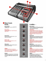
Controls Connectors lndicators
Peak lndicators Equalizers FEEDBACK FINDER'"
I Dl3 PCAH lndicators
Are connected to power amplifier outputs and
indicate peak output level. 0 DB PEAK equals
approximately 25 watts to a 4-ohm load. A 6 dB
change is a 4-times power change; therefore,
-36 dB representsa 6 mW output and +6 dB a
lOOW output. These indicators are also used to
provide an instantaneous readout of feedback
frequency (see FEEDBACK FINDER). (Note that
when the FEEDBACK FINDER isactivated, the
DB PEAK indicators for that channel are
converted to frequency band indicators and do
not indicate the signal level.)
I
PA (Power Amplifier)
Overload Indicators
Light when the power amplifiers exceed approximately 1% d~stortion
level (caused by clipping, overload, or any condition resulting in
imperfect signal amplification). The indicator is sensitive to line
voltage and speaker load conditions. The overload condition can
generally be corrected by turning down the MASTER volume control.
If the indicator remains on, the speaker load may be improper or a
speaker cable may be shorted. It may remain on during SHUTDOWN
activation. Under normal conditions, this Indicator corresponds to a
level of +9 dB on the DB PEAK indicator or 200watts to a4-ohm load.
I Graphic Equdizers
Are two 10-band,fully combining, minimum-phase,octave type,
normally connected to the power amplifier inputs. They provide13dB
boost or cut at 63,125,250,500 Hz, 1,2,4,8, and 16 kHz, plus
BELOW 63 Hz 12 dB/octave cutoff filters. The graphic equalizers pern
adjustment of the sound system frequency response for a tonal
balance appropriate to the performance and a reduction in the
tendency toward feedback. They can also be used to adjust an audio
playback system frequency response to compensate for variations in
electrical and acoust~calresponse that can alter the natural sound of
the recorded material.
The graphic equalizers can also be used to produce dlsco-type
sound by moderate amounts of low- and high-frequency boost.
Note that equalization by ear for proper sound quality requires a
certain amount of skill and time. It is preferableto use a commercially
available equalization analysis system such as the Shure M615AS
Equalization Analyzer System, followed by feedback tuning using the
built-in FEEDBACK FINDER and indicators (see next section).
can result In
IMPORTANT: Don't overequalize! Too much equal~zatlon
unnatural and quite unpleasing sound.
No indicator is provided for either the 63 Hzfilter control or BELOW 63
Hz filter switch; any low-frequencyproblems likely to be encountered
can beeasily removed by adjustment and listening tests. Reduce the
if the sound is
63 Hz equalizer or move the switch to BELOW 63 (T)
boomy" or if extremely low-frequencynoises such as "pop" or wind
noise are causing power amplifier overload.
Since the graphic equalizer controls may overemphasize or remove
desirable program material, you should minimize acoust~cproblems
(includingfeedback) by careful microphone and speaker placement
before equalizing.
The FEEDBACK FINDER uses the LED indicators to providea quick and easy means of determiningthe
frequency (octave band location) of the most prominent feedback tones. The graphic equalizers can
then be used to reduce the system response at these frequencies to sup ress feedback. Connect all
speakers and microphones and place them in their proper positions for tEe performance. Set master
controls and individual input channel MONITOR, EFFECTSIREVERBand EQ controls to 0. Set all other
individual input channel controls to the initial (oran e mark) positions. Set the FEEDBACK FINDER
switch to the desired output channel (A or B). The 8 3 PEAK indicatorsfor the channel selected are now
connected for the feedback indicator function. Adjust the MASTER volume for that channel to just below
feedback. If necessary, turn down the FEEDBACK FINDER THRESHOLD control from the 10 position to
the point where room background noise does not light any DB PEAK indicators. Increase the MASTER
volume until feedback just occurs and note the highest frequency band with a lit LED. Reduce the
equalizer setting in this band until feedback stops. Repeat the last two steps until the feedback sound
becomes a combination of a number of tones, or until one equalizer control has been set to -10.
IMPORTANT Don't overadjust the equalizer! Too much equalization can result in unnatural sound. With
practice, the FEEDBACK FINDER can be used toequalize for feedback without subjecting the audience
to ear-splitting feedback levels.
If operation is in the stereo mode, repeat the above procedure for the second channel, with the first
channel turned off. When completed, perform a listening test using program material similar to the
planned performance and, if necessary, make slight adjustments to the equalizers to provide the most
pleasing sound.
When using one of the graphic equalizers for stage monitor speakers, feedback suppression of the
monitor system is performed after the house system and with the main speakers off. The monitor
speakers must be in their final operating positions relative to the microphones used. Use the same
procedure as for the house system except use the individual MONITOR level and MONITOR MASTER
controls for level adjustments. If more than one performer's microphone is involved, select the lead
performer or center stage microphone for operation in the feedback suppression procedure. NOTE:
During this procedure a person must stand in front of or hold (simulating a performer) the microphone
being equalized. Since excessive low-frequency signals are not usually desirable for stage monitors, it
may be advisable to set the equalizer FLATIBELOW 63 switch of the monitor channel to BELOW 63, the
63 Hz control to -10, and the 125 Hz control to -5. Adjust the FEEDBACK FINDER THRESHOLD,
MONITOR MASTER and EQualizer controls using the procedure previously described. Conduct avoice
test and check for adequate level and intelligibility. Make a similar check of all other microphones being
fed to the monitor system. Intelligibility may be improved if desired by a slight increase of equalizer
controls in the 1 kHz to 4 kHz range, providing the desired level can be maintained without feedback. If
feedback or ringing is encountered at any microphone location, try adjusting the position of and/or the
distance to the nearest speaker.
Moster Controls
Bosically
...
In addition..
.
Monitor Master
Controls monitor mix level to MONITOR
OUTPUT jack.
Monitor Master
Control precedes VOLUME and other channel
controls. Only affected by INPUT ATEN and
channel MONITOR controls.
Reverb Return
Controls reverb level to A and B channel
signal mixes.
Reverb Return
This control follows the INPUT AlTEN, input
VOLUME and EQ, and EFFECTSIREVERB
channel controls, as well as the REVERB EQ
controls. Not affected by the N B PAN pots or
MONITOR controls, or following master
controls.
Reverb HI EQ
Sets reverb signal treble boost or cut for
desired tone shaping.
Reverb HI EQ
Adjusts master reverb signal high-frequency
equalization on both A and B outputs. Does
not affect MONITOR OUTPUT or EFFECTS
OUTPUT.
Reverb LO EQ
Sets reverb signal bass boost or cut for
desired tone shaping.
Reverb LO EQ
Adjusts master reverb signal low-frequency
equalization on A and B outputs. Does not
affect MONITOR OUTPUT or EFFECTS
OUTPUT.
Effects Send
Controls level of effects amplifier signal to
EFFECTS OUTPUT jack.
Effects Send
Affected by channel INPUT AlTEN, EQ,
VOLUME and EFFECTSIREVERB channel
controls. Used for external effects or second
monitor.
A Master
Adjusts overall level of A channel mix.
Controls level of A channel signals from mic
inputs 1-6 and aux inputs 7 and 8 to all A
channel and A+ B outputs.
A Master
A!B mix to the A mix amplifier is controlled by
the N B PAN pot for each channel immediately
preceding the A MASTER control. Does not
affect signals added to COMmon MIX jacks or
EQ and PA INPUTS.
B Master
Adjusts level of B channel mix. Controls level
of B channel signals from mic inputs 1-6 and
aux inputs 7 and 8 to all B channel and A+B
outputs.
B Master
N B mix to the B mix amplifier is controlled by
the N B PAN pot for each channel
immediately preceding the B MASTER
control. Does not affect signals added to
COMmon MIX jacksor EQ and PA INPUTS.
Controls connectors Indicators (continued)
Power and Speaker Connections
Power O N - O H Switch
Applies ac power to power supply (does not switch ac outlet)
Unswitchd AC Grounded Outlet
Provides up to 100 watts of ac power to accessory equipment
(mixer, tape recorder, lamp, etc.). The outlet is not fused and not
switched; use the power switch on the accessory equipment.
The outlet is not intended for use with high-power equipment
such as power amplifiers.
AC Line Cord
Connect to ac power (120 Vac ? lo%, 50160 Hz). Use only 16
AWG (or larger), three-wire extension cords. Console may draw
up to 9 amperes (1100 watts) from ac supply circuit. May be
operated from other voltages (see Service Manual).
1011,250V Fuse
Protects console power supply against overload. (Replace only
with identical size and type: 10A, 250V, type 3AB or ABC.)
Speaker Outputs Jock (4)
Connect to speaker systems such as the Shure 701. Two parallel
jacks are for PA (power amplifier) A and two are for PA B. Do not
connect A and B SPEAKER OUTPUT jacks together as distortion
and possible damage may result; for monophonic output, see
SETUPS section. Remove and replace speaker jack cover when
connecting speakers. Suggested speaker loads for each
amplifier of the console include:
2-Shure Model 701 PRO MASTER'" Speaker Systems (8
ohms each), or
4-Shure Model 702 Stage Monitor Speaker Systems (16
ohms each), or
2-Shure Model 703 PRO MASTER'" Stage Monitors (8
ohms each), or
4-Shure Model SR102 or SR103 Speaker Columns (16
ohms each), or
2-Shure Model SR112 or SR116 Compact Speaker
Systems (8 ohms each).
Connecting too many speakers to either or both output jacks may
result in a combined load below the 4-ohm minimum. Operation
with such a load may cause an excessively high internal
temperature (TEMP WARNING LED turns on), or the PA (power
amplifier) OVERLOAD LED may turn on at lower than normal
levels (before the+6 dB LED). Note that no damage will result;
the console is protected against speaker overloads and shorts.
Also, the console may be operated without speakers (with
headphones) for tape recording.
PATCH BLOCKTM
Rmr Panel
Simplex 24V Switch
Reverb Switch Jack
Turn on when powering low-impedance condenser
microphones from the console; turn off when not used.
Balanced low-impedance microphones may be used in
combination with condenser microphones. NOTE: Do not turn
on when using unbalanced low-impedance microphones.
The built-in 24 Vdc simplex voltage is applied to input
channels 1 through 6 BAL LO IMP connectors to power most
condenser microphones. Make sure the microphone(s) will
operate properly with 24 Vdc open-circuit voltage and a 1.8k
powering resistor.
Provides for connection of remote reverb footswitch; reverb
channel and master controls can be preset and added by
performers when needed. Switch closure acts the same as
turning down the REVERB RETURN control, disabling the
reverb. Footswitch cable need not be shielded.
Monitor Output Jack
Provides unbalanced line level output (intended for
connection to unbalanced auxiliary or line bridging inputs)
for separate monitor amplifier system. Output
(pre-fader) precedes channel VOLUME, EQualization,
EFFECTSIREVERB and PAN controls. Adjust individual
channel MONITOR controls for desired mix, and MONITOR
MASTER control for overall level. Connect to A or B PA (power
amplifier) INPUT or EQualizer INPUT to use console power
amp or graphic equalizer for monitor, or connect to external
power amplifier.
Effects Output Jack
Connect to external effects devices such as echo, delay,
flanger, or phase shifter input. Affected by channel INPUT
ATTEN, VOLUME, EQ and EFFECTSIREVERB controls, and
master EFFECTS SEND control. Connect effects device
output (return) jack to AUX INPUT 7 or 8. Aux channel
VOLUME control becomes effects return control. EFFECTS
OUTPUT jack may be used as second (post-fader) monitor by
connecting to external power amp or console A or B PA
(power amplifier) or EQ INPUT.
A, B Mix Output Jacks
These COMmon MIX (output-input) jacks provide a
post-MASTER volume, pre-graphic equalizer output or input
for picking off the A or B mix for insertion into tape recorders or
other power amplifiers, or inserting external signals from
other PRO MASTER. consoles. The A and B channels may be
combined (mono mix) at this point by connecting these jacks
tnr.nt~rrr
A, B EQ Input Jacks
Provide for insertion of signals from MONITOR or EFFECTS
OUTPUT from the console or from an external mixer, at the
same time disconnecting the normal signal in that channel.
The inserted signal will be affected by the graphic equalizer,
but not by the MASTER volume control. If there is no
connection at the PA INPUT,the inserted signal passes to the
power amplifier, and the graphic equalizer and power
amplifier are used for the monitor or effects system.
Inserted signal is not affected by any PRO MASTER
volume controls, so console should be turned off when
connecting external equipment to these jacks.
)AI B EQ Output Jacks
These COMmon MIX (output-input) jacks provide for picking
off the equalized signal for connection to a tape recorder or
another power amplifier, or insertion of signals from other PRO
MASTER consoles in addition to the existing equalized signal.
lnserted signal is not affected by any console controls.
A, B PA Input Jacks
Provide for insertion of sianals into ~ o w e amolifier
r
from
console outputs (MONIT~R,
E F F E C ~etc.),
,
at the same time
disconnectina the normal sianal in that channel. lnserted
slgnal is not gffected by a n y " P ~ 0MASTER console controls,
so console should be turned off when connecting external
equipment to these jacks.
- A + 0 AUX O U ~JackU ~
Provides aux level mixed A+B (monophonic) signal to tape
recorder, other mixer or amplifier, or house sound system,
Mixed signal is pre-graphic equalizer and affected by all
other A and B console controls. Jack may be connected to EQ
or PA INPUT jack for mixed output on A or B power amplifer.
A
+ 0 MIC Output Jack
Provides balanced, low-impedance, microphone-level mixed
A+B (monophonic) signal to tape recorder or house sound
system when used in conjunction with built-in systems. Allows
PRO MASTER console to be used for mixing, monitoring or
recording. Connect to low-impedance microphone input jack.
Mixed signal is pre-graphic equalizers and is affected by all
other A and B controls.
The PRO MASTER'" is an extremely versatile unit. Its great flexibility is in part achieved by
the many PATCH BLOCK'" (rear panel) inputs and outputs which permit its use in a wide
variety of applications. The setups described in this section offer some idea of the varied
applications of the PRO MASTER. Use only high-quality, shielded patch cords for patching.
Turn PRO MASTER power switch off when making patch connections to avoid possible
high-level transients, noise and hum.
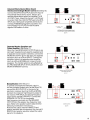
Monophonic Sound Reinforcement (See Setup 1.)
No rear panel patching is required. Plug in the
microphones and left (A) and right (B) speakers,
and set the operating controls as desired. Adjust
the PAN pots to the center (orange mark) position.
SPEAKER OUTPUTS
Stereo Sound Reinforcement (See Setup 1.)
Same as for monophonic, except adjust PAN pots
so that the microphone inputs are routed to the
desired output channel: left (A) and right (B), or to
both channels (orange mark) simultaneously for
center stage inputs.
Mono Sound Reinforcement and Stage
Monitor System (See Setup 2.)
Patch the MONITOR OUTPUT jack to the A EQ
INPUT jack. Connect the monitor speaker(s) to
channel A SPEAKER OUTPUTS and the main
speakers to channel B. Note that the monitor
system is equalized by the channel A graphic
equalizer; if equalization is not desired, the
MONITOR OUTPUT can be patched to the
channel A PA (power amp) INPUT jack instead of
the EQ INPUT. Individual channel MONITOR
controls set the mix and level to be fed to the
monitor system. The MONITOR MASTER adjusts
the overall monitor system level. Adjust the
channel B MASTER and graphic equalizer for the
main speakers. Adjust the PAN pots to the center
(orange mark) position.
MONOPHONIC OR STEREO
SOUND REINFORCEMENT
SETUP 7
SPEAKER
PUTS
.
TpuT
a a
MONO SOUND REINFORCEMENT
AND STAGE MONITOR SYSTEM
SETUP 2
@
Mono Sound Reinforcement, Stage Monitor,
and Stereo Tape RecordIPlayback (See Setup 3.)
Patch the MONITOR OUTPUT jack to the A EQ
INPUT jack.Patch the A+BAUX OUTPUT jack to the
B EQ INPUT jack. Connect the A MIX OUTPUT jack
to the left channel aux input of the tape recorder,
and the B MIX OUTPUT to the right channel aux
input. Connect the monitor speaker(s) to channel
A SPEAKER OUTPUTS and the main speakers to
channel B. Adjust the MONITOR MASTER and
channel A graphic equalizer for the monitor
speakers. Adjust the channel A and B MASTER
volume controls simultaneously to control the main
speakers and tape recorder. The channel B
graphic equalizer is for the main speakers. For
tape playback, connect the tape recorder outputs
to AUX INPUT 7 and 8.
STEREO
TO C H 7 INPUT
RECORDER
TO C H 8 INPUT
OUTPL
.MI)
SPEAXER
FNp~.
.
+" 0
OUTPUTS
7
A*.
L
OUTPUT
A"x
INPUT
MONO SOUND REINFORCEMENT, STAGE
MONITOR. AND STEREO TAPE RECORDIPLAYBACK
SETUP 3
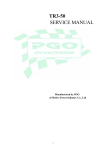
Mono or Stereo Sound Reinforcement and
Mono Tape Record (See Setup 4.)
Connect left and right speakers to the A and B
SPEAKER OUTPUTS. Connect the A+ B AUX
OUTPUT to the tape recorder aux'input jack.
,
A+B
SPEAKER OUTPUTS
I
AUX
IN
MONO OR STEREO SOUND REINFORCEMENT
AND MONO TAPE RECORD
SETUP 4
Two Monitors and Mono "House"
Sound System (See Setup 5.)
When a "house" system is to be used as the prime
sound system, the PRO MASTER can be used as
the system mixer, and also provide two monitor
outputs as follows. Patch the MONITOR OUTPUT
jack to the A EQ INPUT jack, and the EFFECTS
OUTPUT jack to the B EQ INPUT jack. Connect the
A+B MIC OUTPUT to the house system mic input.
Connect SPEAKER OUTPUTS A to vocal monitor
speakers and SPEAKER OUTPUTS B to band
monitor speakers. Adjust MONITOR controls for
vocal monitor and adjust EFFECTS controls for
band monitor. Note that the vocal monitor is
pre-fader and the band monitor is post-fader.
BAND
MONITOR
SPEAKER
VOCAL
MONITOR
SPEAKER
-
.;
,PEAKER
IUTPUTS
0yPuT.
0
Mod
A + B M I C OUTPUT
OUTPUT
?FFEC$
OUTPUT
" '9
.>
INPUT
SYSTEM
TO
HOUSE
MC
SOUND
INPUT
TWO MONITORS AND MONO
HOUSE SOUND SYSTEM
SETUP s
External Effects DeviceIMono Sound
ReinforcementISingle Master Control (See Setup 6.)
Connect the EFFECTS OUTPUT jack to the input of
the external effects device (echo, flanger, etc.),
and the effects device output to a channel 7 or 8
AUX INPUT jack. Adjust the channel 7 or 8 PAN pot
to center. Patch the A EQ OUTPUT jack to the B PA
INPUT jack. Both power amplifiers are fed by the
channel A MASTER and graphic equalizer, and
both SPEAKER OUTPUTS provide the same
signal at 200 watts to 4 ohms.
..
-. I
A EQ OUTPUT
0..
EFFECTS
SPEAKE
OUTPUT-
TO CHANNEL 7 OR 8
AUX INPUT
EXTERNAL EFFECTS DEVlCEiMONO SOUND
REINFORCEMENTiSlNGLE MASTER CONTROL
SETUP 6
Separate Monitor Equalizer and
Power Amplifier (See Setup 7.)
When the A and B SPEAKER OUTPUTS are in use
(and each requires its own graphic equalizer) and
a separate monitor system is desired, connect the
MONITOR OUTPUT jack to the input of a separate
equalizer (such as a Shure SR107). Connect the
equalizer output to a separate power amplifier
(such as a Shure SR105B) and connect monitor
speakers. The monitor system is only affected by
the PRO MASTER INPUT ATTEN, MONITOR, and
MONITOR MASTER controls.
MAIN
WPEA3
I
SPEAKtn
OUTPUTS
MONITOR
I
SEPARATE MONITOR EQUALIZER
AND POWER AMPLIFIER
SETUP 7
Biamplification (See Setup 8.)
To provide a monophonic biamped output to
two-way speaker systems such as the Shure 701,
connect the B EQ OUTPUT to the input of an
electronic crossover (such as the Shure SR106).
Connect the crossover high-frequency output to
the channel A PA INPUT, and the low-frequency
output to the channel B PA INPUT. Connect the
SPEAKER OUTPUTS A to the speaker
high-frequency input jack and the SPEAKER
OUTPUTS B to the speaker low-frequency input
jack. (Refer to the speaker system data sheet for
biamping modification instructions.)
Note that the output channel A MASTER and
graphic equalizer are not operative; the channel B
MASTER and graphic equalizer adjust the output
signal to the speakers.
...*,
A PA INPUT
BlAMPLlFlCATlON
SETUP 8
1. Position the microphones and connect them to the
PRO MASTER'". Use both inputs on each channel if
more than six microphones are to be connected.
Use low-impedance microphones and cables to
minimize loss and interference if long microphone
cable lengths are needed.
2. Position the speakers and connect them to the
PRO MASTER. Make sure the combined speaker
load is not less than 4 ohms on each channel. Use
minimum cable lengths to maximize output power.
Use the proper cable size for the required length.
3. Make any rear-panel patching connections
required (refer to SETUPS section). All patching
connections except the A+ B MIC OUTPUT are
standard two-conductor, '/'-inch phone jacks.
4. Connect any external effects device to the PRO
MASTER EFFECTS OUTPUT and AUX INPUT
jacks. Power for the external effects device can be
obtained from the PRO MASTER rear-panel
UNSWITCHED AC receptacle (100 watts
maximum).
5. Connect the PRO MASTER line cord to an ac
source capable of supplying 1100 watts. If
extension cords are required, make sure they are
16 AWG or larger.
6. Make sure the PRO MASTER air louvers are not
blocked. Check to make sure the air filter is clean.
7. In low ambient light conditions, a high-intensity,
low-wattage lamp (not supplied) can be plugged
into the rear-panel UNSWITCHED AC receptacle
(100 watts maximum).
8. Set the front-panel controls to their initial settings
(orange marks). Set the INPUT ATTEN controls for
the usage on each input. Turn on the rear-panel
power ON-OFF switch.
9. Adjust the A and B MASTER volume controls to the
desired level. Using program material similar to the
actual performance, adjust the PAN, MONITOR,
EFFECTSIREVERB and EQ controls as desired for
the most pleasing sound.
10. Using the FEEDBACK FINDERTM,
set the equalizers
for the highest feedback-free sound level. The
equalizer controls can then be "touched up" for
most pleasing sound.
11. During operation, observe the various LED
indicators for possible setting corrections:
A. INPUT CLIP-If on constantly, use the INPUT
ATEN to reduce the input signal and eliminate
the distortion. (Set for occasional flashing.)
Mcrintencrnce
The PRO MASTER is an exceptionally
well-designed unit. All components are of the
highest quality, operating well within their
respective ratings to assure long life. The
following list of Do's and Don'ts describes
minimal operating precautions and
maintenance to provide years of dependable
service.
DO clean the air filter every 100 hours of
operation (more frequently in dusty or dirty
areas). Stand the console on its rear
bumpers, remove the screw securing the
filter, and slide it out of its slot. Rinse the filter
in water or a mild detergent solution, allow to
dry, and replace.
DO unplug the console before cleaning. DO
clean the outer surfaces of the console with a
clean, damp cloth and mild detergent.
DON'T use strong solvents or cleaning fluids.
DO use a 16 AWG or larger heavy-duty
extension cord when additional line cord
length is needed.
DON'T operate the console with air louvers
blocked, or placed on a radiator or
heat-producing equipment. Avoid operation
in direct, hot sunlight.
DON'T replace the rear-panel fuse with a
different size or type. Use only 10A, 250V,
type 3AB or ABC.
DON'T connect the A and B speaker outputs
together (see text for monophonic setups).
DON'T risk fire or shock hazard by operating
the console in rain.
DON'T use unbalanced low-impedance
microphones with the SIMPLEX 24V switch
on; turn off the switch if not required for
powering condenser microphones. If
simplex power is in use, connect unbalanced
low-impedance microphones through a line
matching transformer (Shure A95FP) to a HI
IMP INPUT
B. DB PEAK-Observe action to monitor output
power level and channel balance.
C. PA OVERLOAD-If on constantly, reduce
volume and/or check speaker load.
D. TEMP WARNING-Check for air blockage,
dirty air filter, shorted speaker cable or
excessive heat near the console.
E. SHUTDOWN-Check for excessive console
heating or cooling fan failure.
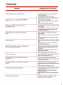
Troubleshooting
Should any difficulty be encountered in
console operation, the problem can often be
traced to some simple source such as an error
in interconnection. The following is offered as a
basic guide to this type of problem.
Troubleshooting
-
- -
Symptom
Probable Cause or Correction
Console is "dead" (no output, POWER LED off)
1. Check that ac power source is "live" and that
console is plugged in.
2. Check that power ON-OFF switch is on.
3. Check that rear-panel fuse (IOA, 250V) is good.
Console appears to be overheating (TEMP WARNING
LED on)
1. Check air louvers for blockage.
2. Check for proper speaker load or shorted speaker
cable.
3. Check air filter and clean if necessary.
Console power amplifiers turn off and remain off
(SHUTDOWN LED on)
1. Turn MASTER controls down for one minute to allow
proper cooling.
2. Turn console off for a few seconds and turn back on.
3. If shutdown persists, have console checked by
qualified service personnel.
No signal at speaker (all console functions appear
normal)
1. Check for defective or improperly connected
speaker cables.
2. Check for improper connections to EQ or PA INPUT
jacks.
3. Check settings of channel VOLUME and MASTER
volume controls.
Console fuse blown
1. Replace with identical fuse (IOA, 250V, type 3AB or
ABC).
2. If second fuse blows, have console checked by
qualified service personnel.
One of two inputs on same channel not working properly
(both %-inch and 3-pin jacks in use)
1. Make sure similar microphones are used on both
inputs, and microphone impedances match the
inputs used.
2. Make sure microphone is not used with accessory
equipment on other input.
3. Make sure both microphone switches are on.
INPUT CLIP LED flashing
1. Adjust INPUT ATTEN to reduce channel input level.
2. Reduce input signal level at source.
PA OVERLOAD LED flashes while DB PEAK indicators
read less than + 6
1. Check for defective (shorted) speaker cable.
2. Check that load impedance is not too low (too many
speakers are connected).
Loud noise clicks when certain microphones or cables
are used
1. SIMPLEX 24V switch is on (when not needed).
2. Unbalanced cable used when SIMPLEX 24V switch
is on.
3. Check for defective microphone cables.
No monitor output (program output normal)
1. Check monitor output connection to EQ or PA INPUT,
or external amplifier.
2. Make sure MONITOR and MONITOR MASTER
controls are turned up.
3. Monitor speaker volume control (if present) turned
down.
Sound quality poor (weak or thin)
1. Excessive equalization on graphic equalizers.
2. Defective input or patching cables.
Type: Solid-state stereo power console using discrete
components and integrated circuits
Inputs: Eight input channels: six high- andior balanced
low-impedance mic inputs, plus two aux inputs
Graphic Equalizers: Two 10-band, fully combining,
minimum-phase, octave type, normally connected to
power amplifier inputs; 13 dB boost or cut at 63,125,
250,500 Hz, 1 , 2 , 4 , 8 and 16 kHz; BELOW 63 Hz 12
dBloctave cutoff filters (10 dB down at 31 Hz)
Power Output:
Both channels
One channel
driven
driven
Per channel14 ohms
200W min.
240W typical
Per channel18 ohms
125W min.
145W typical
Measured at 1 kHz, 120 Vac, 1% THD
Distortion: THD typically less than 0.1% at 40 Hz and
1 kHz, 0.25% at 15 kHz, IM distortion typically less than
0.25% (One channel driven, 180W or less to 4 ohms,
110W or less to 8 ohms, measured from low-impedance
input with individual and master controls at typical
settings)
Low- and High-Frequency
lnput Equalization: 213 dB at 100 Hz and 10 kHz
lnput Clipping Indicators: Light 3 dB below input or
equalizer clipping level
DB Peak Indicators: Indicate power amplifier peak
voltage; + 6 dB LED indicates 100 watts sine-wave
output to 4-ohm load
PA Overload Indicators: Light when power amplifier
THD exceeds 1%; fully on at 5%
Input Sensitivity:
BAL LO IMP
0.6 mV
(full power output)
HI IMP
8 mV
AUX
21 5 mV
EQ INPUT
960 mV
PA INPUT
960 mV
lnput Clipping Level:
BAL LO IMP 700 mV to 21 mV (INPUT ATTEN -30 to 0)
1OV to 335 mV (INPUT AlTEN -30 to 0)
HI IMP
30V to 1OV (VOLUME from 0 to 10)
AUX
Voltage Gain:
94 dB BAL LO IMP INPUT to SPEAKER OUTPUTS
71 dB
43 dB
64 dB
77 dB
74 dB
16dB
58 dB
81 dB
OdBE
30 dB
Levels and Impedances:
Circuit
Nominal Maximum Actual
Working
Level
Level
Impedance Impedance
BAL LO IMP INPUT 5 mV
HI IMP INPUT
50mV
0.5V
AUX INPUT
MIX OUTPUT
1V
EFFECTS OUTPUT 1V
MONITOR OUTPUT 1V
EQ INPUT
1V
EQ OUTPUT
1V
A+ B AUX OUTPUT 1V
A+ B MIC OUTPUT 5 mV
PA INPUT
1V
SPEAKER OUTPUT -
700 mV
10V
30V
9V
9V
9V
10V
9V
9V
75 mV
10V
28.3V
HEADPHONES
10V
-
1k
145k
50k
2.4k
2.4k
2.4k
50k
2.4k
5k
70 ohms
50k
19-300 ohms
1OOk or less
1Ok or less
2k or more
2k or more
2k or more
1Ok or less
2k or more
2k or more
19-300 ohms
1Ok or less
4 ohms or
more
360ohms 4 ohms or
more
Frequency Response: &2 dB, 40 to 20,000 Hz, BAL
LO IMP INPUT to SPEAKER OUTPUTS
Hum and Noise: (20 Hz to 20 kHz) - 127 dBV
equivalent input noise (BAL LO IMP)
Noise: (300 Hz to 20 kHz) -128 dBV equivalent input
noise (BAL LO IMP)
Signal-to-Noise Ratio: Greater than 80 dB (below full
output) at typical control settings (orange marks,
MASTER at 5, INPUT AlTEN at -12)
Mic lnput Simplex Power: 24 Vdc open-circuit,
1.8k series resistance
Power Requirements: 120 Vac +lo%, 50160 Hz;
1100W max. (For other voltages, see Service Manual)
Environmental Conditions
Operating: - 7" to 43°C (20" to 110°F)
Storage: -40" to 74°C (-40" to 165°F)
Overall Dimensions: 190 mm H x 584 mm W x 508 mm
D (71/2 in. x 23 in. x 20 in.)
Weight: 21.3 kg (47 Ibs.)
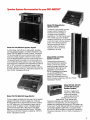
Speaker Systems Recommended for your PRO MASTERTM
Speaker system
Model 701 PRO MASTER Speaker System
A wide-range, high efficiency, lightweight, portable,
two-way speaker system-an ideal companion to the
Model 700 PRO MASTER Power Console. The Model
701 provides high SPL sound reinforcement of wide
frequency range program material in every location
from the largest auditoriums to the most intimate clubs.
The speaker system consists of a 15-inch woofer in a
front-ported bass reflex cabinet, and a high-frequency
horn and driver combination with adjustmentfor either a
60" or 120" horizontal horn dispersion angle. Easily
biamped. Maximum recommended amplifier output to
8 ohms: 150 watts continuous. Frequency response: 50
Hz to 15 kHz. Impedance: 8 ohms.
A compact, high-quality, two-way
speaker system designed for
localized sound coverage in
on-stage monitor (foldback)
applications. The 702 may be used
with virtually any power amplifier
capable of delivering up to 50 watts
to a 16-ohm load. It can be placed in
either of two slanted positions
facing the performer. Built-in
volume control. Frequency
response: 100 Hz to 20 kHz.
Impedance: 16 ohms.
Model SR102 and SR103
Speaker Columns
Outstanding performance in
sound reinforcement systems.
These columns have a wide
frequency range, distortion-free
reproduction and high sound
penetration power. Model
SR102 is designed for portable
use and Model SR103 for
permanent installation. Power
rating: 100 watts maximum to 16
ohms. Frequency response: 100 Hz I
Impedance: 16 ohms.
Model 703 PRO MASTER Stage Monitor
This is a rugged, professional,two-way monitor system
designed for years of hard on-stage use. It has two
8-inch speakers and a high-frequency driver coupled
to a 120" radial horn. Horn dispersion angle may be
reduced to 60" for tighter control of foldback signal.
Can be positioned at 30" or 60" angle to the stage.
Maximum recommended amplifier output: 100 watts
continuous to 8 ohms. Frequency response: 100 Hz to
16 kHz. Impedance: 8 ohms.
studio monitor and club
applications. They feature wide
frequency response, low distortion and smooth
dispersion characteristics, and are designed to
operate with amplifiers delivering up to 100 watts to an
8-ohm load. The SR112B and SRI 12W are designed for
permanent installation (SR112W is woodgrain finish),
and the SR116B is portable for temporary installations.
Frequency response: 45 Hz to 16 kHz. Impedance: 8
ohms.
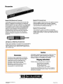
Accessories
Model SR106 Electronic Crossover
Model A7C Console Cover
A selectable-frequency dividing network (500, 800,
2600 Hz), designed for use with two- or three-way
speaker systems such as the Model 701 in high-quality
sound systems. It uses the principle of biamplification
to separate an audio console or mixer-preamplifier
output into two frequency bands for distribution to
separate power amplifiers. The SR106 has both
professional three-pin and phone jack inputs and
outputs. Occupies only 1%-inch of rack space.
Combined frequency response: flat -.2 dB, 20 to
20,000 Hz.
Made of rugged, reinforced vinyl, this useful accessory
protects against weather and scrapes. Zippered
closures permit quick setups and takedowns. Front
cutout provides for carrying handle use.
Model A7S Console Stand
This handsome, sturdy unit makes a convenient
support when a table or desk is not available. Made of
durable steel tubing, it is quickly and easily set up and
taken down.
A95 Series Line Matching Transformers
Adapt high-impedance microphone to low-impedance
console inputs, and low-impedance microphone to
high-impedance inputs. Model A95FP plugs directly
into console input.
Service
Guarantee
This Shure product is guaranteed in normal use
to be free from electrical and mechanical defects
for a period of one year from date of purchase.
Please retain proof of purchase date. This
guarantee includes all parts and labor. This
guarantee is in lieu of any and all other
guarantees or warranties, express or implied,
and there shall be no recovery for any
consequential or incidental damages.
If information or service should be required, contact your local
Shure PRO MASTER'" dealer explaining your difficulty in
detail. In addition, the Shure factory service department will
be ready to assist you immediately upon request.
Shipping Instructions
Carefully repack the unit and return it prepaid to:
Shure Brothers Incorporated
Attention: Service Department
1501 West Shure Drive
Arlington Heights, Illinois 60004
If outside the United States, return the unit to your dealer or
Authorized Shure Service Center for repair. The unit will be
returned to you prepaid.
Shure Brothers Inc., 222 Hartrey Ave., Evanston, IL60204 U.S.A.
Copyr~ght1979, Shure Brothers Inc
27A1428 (SA)
Pr~ntedin U.S.A.