1
VISTA- 4
8
D
!#"%$& ')( *!+-,/.10 2 34"5(6+
ARMED
READY
CPU
ON
OFF
ARMED
1
OFF
2
AWAY
3
STAY
READY
4
MAX
5
TEST
6
BYPASS
7
INSTANT
8
CODE
9
CHIME
READY
K0749-4EN 1/03
0
#
ii
Table Of Contents
• • • • • • • • • • • • • • • • • • • • • • • • • • • • • • • • • • • • •
Features and Installation Highlights ................................................................................................................ 1-1
Capabilities ............................................................................................................................................................. 1-1
Functions ................................................................................................................................................................. 1-1
Compatible Devices ................................................................................................................................................ 1-2
Important Installation Highlights (Installer Please Read) .............................................................................. 1-2
Mounting and Wiring the Control ...................................................................................................................... 2-1
Cabinet and Lock.................................................................................................................................................... 2-1
Mounting the PC Board Alone.............................................................................................................................. 2-1
Mounting Board with RF Receiver ...................................................................................................................... 2-2
Wiring to Keypads.................................................................................................................................................. 2-3
Sounder (Siren) Connections ................................................................................................................................ 2-4
Wiring the AC Transformer.................................................................................................................................. 2-4
Backup Battery....................................................................................................................................................... 2-5
Earth Ground.......................................................................................................................................................... 2-5
Basic Wired Zones .................................................................................................................................................. 2-6
Zone Doubling/Double-Balanced Zones ....................................................................................................................... 2-6
Smoke Detectors ..................................................................................................................................................... 2-6
4219/4229 Expansion Zones.................................................................................................................................. 2-7
6164 Keypad Expansion Zones............................................................................................................................. 2-8
Installing the RF Receiver .................................................................................................................................... 2-9
Installing a 5800TM Module................................................................................................................................. 2-9
Installing the Transmitters .................................................................................................................................. 2-9
Installing a Keyswitch......................................................................................................................................... 2-10
Connecting Relay Modules.................................................................................................................................. 2-11
Powerline Carrier Devices................................................................................................................................... 2-12
On-Board Triggers................................................................................................................................................ 2-13
Phone Line Connections ...................................................................................................................................... 2-14
Alternative Communications Media (ACM) Connections............................................................................... 2-14
Programming Overview......................................................................................................................................... 3-1
About Programming............................................................................................................................................... 3-1
Zones and Partitions .............................................................................................................................................. 3-1
Keypads ................................................................................................................................................................... 3-2
Wireless Receiver Transmitters, and Wireless Keys (keyfobs)........................................................................ 3-2
Pager Programming ............................................................................................................................................... 3-2
Function Keys ......................................................................................................................................................... 3-3
Output Devices ....................................................................................................................................................... 3-3
Zone Type Definitions............................................................................................................................................ 3-3
Mechanics of Programming................................................................................................................................... 3-6
Data Field Programming....................................................................................................................................... 4-1
About Data Field Programming ........................................................................................................................... 4-1
Programming Data Fields..................................................................................................................................... 4-1
System Setup Fields............................................................................................................................................... 4-1
Zone Sounds & Timing .......................................................................................................................................... 4-2
Dialer Programming (∗40 – ∗50) .......................................................................................................................... 4-3
System Status Report Codes................................................................................................................................. 4-5
Miscellaneous System Fields................................................................................................................................ 4-6
Pager Programming Fields ................................................................................................................................... 4-9
Miscellaneous System Fields.............................................................................................................................. 4-10
Keypad Programming Fields .............................................................................................................................. 4-12
iii
Table Of Contents (continued)
Menu Mode Programming..................................................................................................................................... 5-1
About Zone Programming (∗56 and ∗58 Menu Modes) ..................................................................................... 5-1
∗56 Zone Programming Procedure....................................................................................................................... 5-1
Completing Zone Programming............................................................................................................................ 5-4
∗58 Expert Programming Mode Procedures ....................................................................................................... 5-4
Wireless Key Programming Templates............................................................................................................... 5-6
About Output Device Programming (*79/*80 Menu Mode).............................................................................. 5-8
*79 Menu Mode: Output Device Mapping........................................................................................................... 5-8
*80 Menu Mode: Defining Output Functions ................................................................................................... 5-10
About Zone Lists (∗81 Menu Mode) ................................................................................................................... 5-13
Zone List Programming....................................................................................................................................... 5-13
About Function Key Programming (∗57 Menu Mode)..................................................................................... 5-14
Programming Function Keys.............................................................................................................................. 5-14
About Descriptor Programming (*82 Menu Mode).......................................................................................... 5-15
Configurable Zone Type Programming (*83 Menu Mode) .............................................................................. 5-16
Programming Installer and User Schedules .................................................................................................... 5-18
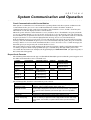
System Communication and Operation............................................................................................................ 6-1
Panel Communication with Central Station ...................................................................................................... 6-1
Report Code Formats ............................................................................................................................................. 6-1
Robofon 8 Format ................................................................................................................................................... 6-3
ADEMCO Contact ID® .......................................................................................................................................... 6-4
Security Codes ........................................................................................................................................................ 6-5
Keypad Functions................................................................................................................................................... 6-6
Panic Keys............................................................................................................................................................... 6-6
Follow-Me Feature ................................................................................................................................................. 6-7
Setting/Adjusting the Real-Time Clock............................................................................................................... 6-7
Various System Trouble Displays ........................................................................................................................ 6-8
Testing the System................................................................................................................................................... 7-1
About Test Procedures........................................................................................................................................... 7-1
System Test............................................................................................................................................................. 7-1
Go/No Go Test Mode .............................................................................................................................................. 7-2
Dialer Communication Test and Periodic Test .................................................................................................. 7-2
Automatic Standby Battery Tests........................................................................................................................ 7-2
Specifications & Accessories................................................................................................................................ 8-1
Security Control...................................................................................................................................................... 8-1
Compatible Devices ................................................................................................................................................ 8-1
5800 Series Transmitter Input Loop Identification........................................................................................... 8-3
Limitations and Warranty..................................................................................................................................... 9-1
iv
S E C T I O N
1
Features and Installation Highlights
• • • • • • • • • • • • • • • • • • • • • • • • • • • • • • • • • • • • • • •
Capabilities
• Supports 3 partitions, which can protect three independent areas, as if each area had its own
control.
• Common area option allows either of the other two partitions to arm, while leaving a common
area (ex. lobby or foyer) disarmed for access into the remaining disarmed partition.
• Supports up to 48 protection zones plus 16 keyfob zones (zones 49-64) for total of 64 zones:
-- 8 basic wired zones (zones 1-8) with optional zone-doubling/double-balanced zone feature
-- Up to 40 additional wired zones (zones 9-48) using up to 5 8-zone 4219/4229 modules (each 4zone 6164 in which zones [EOLR or double-balanced] are used consumes one 4229 location)
-- Supports up to 40 wireless transmitter zones (5800 series; zones 9-48); additional wireless
zones are available if less than 16 keyfob zones are used.
-- Supports up to 4 installer-configurable zone types
Up to 48 Security Codes, each with separate authority levels and partition access
Downloading: Via an IBM compatible computer, Compass downloading software, and an ADEMCO
CIA/CIA-EU modem.
Functions
• Single-button arming feature: Can use dedicated keys to arm the system AWAY or STAY
• Up to 32 Schedules, to control output devices, to determine when users have access, and/or to autoarm/disarm (or allow disarm) the system
• Up to 4 Keypad macros, which can be activated by wired/wireless keypads
• Paging feature allows certain system conditions to be reported to up to 3 pager phone numbers; can
use a dedicated key on keypads to send a signal to a pager
• User programmable telephone number for audio “beeps” reporting of alarms to the user (follow-me
feature).
• Built-in Telephone Line Monitoring option can monitor the telephone line voltage and can cause a
local display, or a display and trouble/alarm sound.
• Event Logging records up to 250 selected events in a history log; control and readout from the log
is done via Ademco Compass Downloader software or using an installer/master code at an alpha
display keypad for local display.
• Installer-customized zone descriptors for all zones (useful only when using alpha display keypads).
• Optional siren supervision detects external sounder wiring short or open; causes a trouble
condition, keypad display, and sends a report to the central monitoring station, if enabled.
• Optional RF jam detection for wireless systems detects a condition that may impede proper RF
reception (i.e., jamming or other RF interference); causes keypad display, sends a report to the
central monitoring station (if trouble reporting is enabled), and can optionally send a tamper
alarm if detected during the armed mode.
• Individual user code selection for open/close reporting to central monitoring station (set when
adding a user code, attribute 6).
1-1
Installation and Setup Guide
Compatible Devices
• Supports up to 8 Addressable Keypads: 6148/6150 Fixed-Word Display Keypads, 6164 Alpha
Keypad, 6128RF/6128RFH/6150RF/6160RF Keypad/Transceivers, 6160V Voice Keypad
• Supports up to five 4219, 4229 addressable basic wired zone expander modules
• Supports 5881/5882EU/5882EUH/5883 series receiver and 5800/5800EU/5800H/5800AP series
transmitters
• Outputs from up to 16 relays, two on-board triggers, and/or Powerline Carrier Devices (X-10 type)
-- Use any combination of 4204, 4229, 6164 relays and/or Powerline Carrier Devices.
-- Output functions (up to 48)
• Alarm power output provides a 12VDC, 2 AMP output that can drive compatible sounders with a
steady output for burglary/panic, or temporal pulse (3 pulses – pause – 3 pulses – pause – 3 pulses.
. .) for fire. Uses current limiting circuitry for protection.
• Auxiliary Power Output: 12VDC, 600 mA maximum (uses PTC for protection).
• Backup Battery: Rechargeable (sealed lead-acid type) 12VDC, 6AH minimum.
• Audio Alarm Verification (using AAV module, such as ADEMCO UVS); can be used in conjunction
with an output trigger to permit voice dialog between an operator at the central station and a
person at the premises.
• Alternative Communication Media: Primary telephone number messages can be reported via ECP
connection to Ethernet TCP-IP Internet
• AC Power Supply: Wired-in or Plug-in 110 (e.g 1321)/220VAC transformer
Important Installation Highlights (Installer Please Read)
• This system uses addressable keypads and Zone Expander Modules (see table of addresses in
Programming Overview section).
• Keypads must be set for addresses 16-23 (first keypad is address 16, which is different from
previous controls) and programmed in data fields *190-*196.
• Zone Expander Modules must be set for specific addresses (07-11), based on the zone numbers used
(see table of addresses in 4219/4229 Expansion Zones section).
• 4204 Relay Modules must be set for specific addresses (12-15; see Connecting Relay Modules
section).
• 6164 Keypads must be set for two addresses: a keypad address and a zone expander address (if
using the keypad’s expansion zones).
• This control will not power-up unless AC mains is connected (will not power-up on battery alone).
However, once the system is powered up, it will operate on battery power in the event of AC mains
loss.
• Relays have two programming menu modes: Use *79 Menu mode to map module addresses and
device (output) numbers. Use *80 Menu mode to define the output functions (see Output Device
Programming section).
• This system supports programmable function keys. Use *57 Menu mode to define the function keys
(see Function Key Programming section).
• This system provides various paging features. Refer to the Programming Overview section for a
summary on pager programming.
1-2
S E C T I O N
2
Mounting and Wiring the Control
• • • • • • • • • • • • • • • • • • • • • • • • • • • • • • • • • • • • • • •
This section describes the procedures for mounting and wiring this control and its peripheral devices.
In the following subsections, procedures are listed in the left column, while notes and pertinent
explanations are provided in the right column.
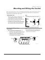
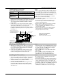
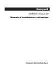
Cabinet and Lock
Notes
1.
• The cabinet can be closed and secured without a
lock by using 2 screws in the cover's edge.
SNAP
TAB
PUSH
SNAP
TAB
UNLOCKED
CABINET DOOR
BOTTOM
STEP 1
cab_lock_snap-001-V0
LOCKED
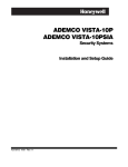
Position the lock in the hole, making certain that the
latch will make contact with the latch bracket when
the door is closed. When correctly positioned, push
the lock until it is held securely by its snap tabs.
PUSH
ON LOCK
UNTIL IT
IS SEATED
SECURELY
ADEMCO
3.
CHECK
POSITION
ADEMCO
2.
Mount the control cabinet to a sturdy wall in a clean,
dry area, which is not readily accessible to the
general public, using fasteners or anchors (not
supplied) with the four cabinet mounting holes.
Remove cabinet door, then remove the lock knockout
from the door. Insert the key into the lock.
STEP 2
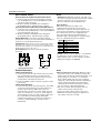
Figure 1. Installing the Cabinet Lock
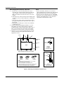
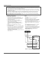
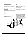
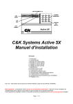
Mounting the PC Board Alone
Notes
(no RF Receiver)
1. Hang two short mounting clips (provided) on the
raised cabinet tabs (see Detail B in Fig. 2).
2. a. Insert the top of the circuit board into the slots at
the top of the cabinet. Make sure that the board
rests on the correct row (see Detail A).
b. Swing the base of the board into the mounting
clips and secure the board to the cabinet with the
accompanying screws (see Detail B).
• Before installing the cabinet's contents, remove
the metal cabinet knockouts required for wiring
entry. Do not remove the knockouts after the
circuit board has been installed.
CIRCUIT
BOARD
CABINET
CIRCUIT
BOARD
CABINET
+
+
DETAIL A
SIDE VIEW
OF BOARD
SUPPORTING
SLOTS
DETAIL B
SIDE VIEW
OF MOUNTING
CLIPS
MOUNTING-001-V0
Figure 2. Mounting the PC Board
2-1
Installation Instructions
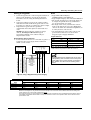
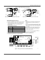
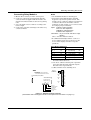
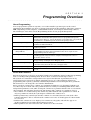
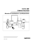
Mounting Board with RF Receiver
Notes
1.
• Do not mount the cabinet on or near metal
objects. This will decrease RF range and/or block
RF transmissions from wireless transmitters.
• Do not locate the cabinet in an area of high RF
interference (revealed by frequent or prolonged
lighting of the LED in the receiver after it is
operational (random flicker is OK)
2.
3.
a. Remove the receiver board from its case, then
insert the top of the board into the slots at the top
of the cabinet, as shown in Detail A in Figure 3.
Make sure that the board rests on the correct row
of tabs.
b. Swing the base of the board into the mounting clips
and secure it to the cabinet with the accompanying
screws.
c. Insert the top of the control's board into the slot in
the clips and position two clips at the lower edge of
the board.
d. Swing this board into place and secure it with two
additional screws.
Insert grounding lugs (supplied with the receiver)
through the top of the cabinet into the left-hand
terminals of the antenna blocks (at the upper edge of
the receiver board) and secure them to the cabinet
top with the screws provided, as shown in Detail B.
Insert the receiver's antennas through the top of the
cabinet, into the blocks' right-hand terminals, and
tighten the screws.
CABINET
A
B
+
CABINET
BOARD
SUPPORTING
SLOTS
RECEIVER CIRCUIT BOARD
+
MOUNTING
CLIP
CIRCUIT
BOARD
CONTROL
CIRCUIT
BOARD
DETAIL A
MOUNTING
CLIP
SIDE VIEW
OF BOARD SUPPORTING SLOTS
INSTALLATION WITH RECEIVER CIRCUIT BOARD
ANTENNA
(2)
SCREW
(2)
GROUNDING
LUG
(2)
WHITE
MOUNTING
CLIP
BLACK
MOUNTING
CLIP
RED
MOUNTING
CLIP
NOTE
A COMBINATION OF THESE MOUNTING CLIPS HAS BEEN
INCLUDED IN YOUR INSTALLATION KIT.
USE THE APPROPRIATE CLIPS FOR MOUNTING.
IF NO RF RECEIVER IS USED, MOUNT THE PC BOARD USING
EITHER THE WHITE OR BLACK CLIPS, WHICHEVER ARE
INCLUDED IN THE CONTROL PANEL'S HARDWARE KIT.
ANTENNA
MOUNT
(2 PLACES)
DETAIL B
ANTENNA AND GROUNDING
LUG INSTALLATION
pc_mount-001-V1
Figure 3. Mounting the PC Board and RF Receiver
2-2
Mounting and Wiring the Control
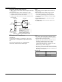
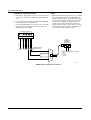
Wiring to Keypads
Notes
1.
• Typical Fixed-Word Display:
6128RF/6148/6150/6150RF/6150V
• Typical Alpha Display: 6160/6160V/6160RF/6164
• The system supports up to 8 keypads, which can
be assigned to partitions in any combination
(see program fields *190-*196).
• For single 4-wire runs, determine the current
drain of all units, then refer to the Wiring Run
chart to determine the maximum length that can
be safely used for each wire size.
• Use supplementary power if the control’s aux.
power load for all devices exceeds 600mA.
Suggested power supply: AD12612
2.
3.
Connect keypads to the control’s keypad terminals as
shown on the Summary of Connections diagram.
Determine wire size using the Wiring Run Chart
below.
Set keypad addresses. Refer to the address setting
instructions included with the keypads and set each
keypad device address according to the chart at right.
Program the keypad addresses, partition
assignments and sound options in data fields *190*196.
NOTE: Each keypad must be assigned a unique
address, starting at address 16. Keypads
programmed with the same address will give
unpredictable results.
Supplementary Power (optional)
1. Connect as shown. Be sure to connect the negative (–)
terminal on the power supply unit to terminal 4
(AUX –) on the control.
SUPPLEMENTARY
POWER SUPPLY
16**
17
18
19
Keypad
no. 5
no. 6
no. 7
no. 8
Address
20
21
22
23
Keypads powered from supplies that do not have a
backup battery will not function if AC mains power
is lost. Make sure to power at least one keypad in
each partition from the control’s auxiliary power
output.
pwr_sup_conn-008-V0
TO KEYPAD YEL DATA WIRE (<)
TO KEYPAD GRN DATA WIRE (>)
TO KEYPAD RED POWER WIRE (V+)
TO KEYPAD BLK GROUND WIRE (V-)
TO KEYPAD GRN DATA WIRE (>)
TO KEYPAD YEL DATA WIRE (<)
IMPORTANT:
MAKE THESE
CONNECTIONS
DIRECTLY TO
SCREW
TERMINALS AS
SHOWN.
no. 1
no. 2
no. 3
no. 4
** The first keypad is address 16, which is always
enabled and set for partition 1 with all sounds on.
AUX. AUX. DATA DATA
IN OUT
+
–
4
5
6
7
–
TO KEYPAD BLK GROUND WIRE (V-)
TO KEYPAD RED POWER WIRE (V+)
+
CONTROL TERMINAL STRIP
Keypad Addresses
Keypad
Address
Figure 4. Using a Supplementary Power Supply
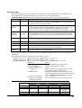
Wiring Run Chart For Devices* Drawing Aux Power From The Control (12V+ & 12V–)
Wire
Size
0.6mm O.D.
0.8mm O.D.
1mm O.D.
1.2mm O.D.
TOTAL CURRENT DRAIN OF ALL DEVICES CONNECTED TO A SINGLE WIRE RUN
50 mA or less
100 mA
300 mA
500 mA
600 mA
152m
76m
24m
15m
13m
228.6m
116m
40m
24m
20m
396m
198m
67m
40m
35m
457m
305m
100m
70m
52m
* Includes Keypads, RF Receivers, Zone Expander/Relay Units, or TeleCommand Phone Module.
Maximum wire lengths for any device that is wired directly to the control can also be determined from the Wiring Run
Chart, based on the current drain of that device alone.
The length of all wire runs for all partitions combined must not exceed 457m when unshielded quad conductor cable is
used (228m if shielded/screened cable is used). This restriction is due to the capacitive effect on the data lines when
quad cable is used.
2-3
Installation Instructions
Sounder (Siren) Connections
Notes
1. Make sounder connections to alarm output terminals 3
(+) and 4 (–).
For supervised output, continue with steps 2 and 3.
2. Cut the red Siren Supervision Jumper located above
terminals 2 and 3 on the control board.
3. Connect a 2k ohm resistor across the terminals of the
last sounder.
• The 12VDC sounder output activates when an
alarm occurs.
• Total current drain from this output cannot
exceed 2 amps (going beyond 2 amps will
overload the power supply, or may cause the
electronic circuit protecting the sounder output
to activate).
• You must install a battery, since the battery
supplies this current.
• Do NOT perform steps 2 and 3 if using a selfactivated siren.
4
7
ALARM
OUTPUT
TERMINALS
EXTERNAL ALARM
SOUNDER
7
+
3
OBSERVE
POLARITY
+
2
CUT RED JUMPER ON CONTROL
BOARD TO ENABLE SIREN
(SOUNDER) SUPERVISION.
2000
OHM
EOL
RESISTOR
IF SIREN SUPERVISION IS ENABLED
(RED JUMPER ON CONTROL BOARD IS CUT)
CONNECT A 2000 OHM RESISTOR ACROSS
THE EXTERNAL SOUNDER AS SHOWN BY
THE DOTTED LINE.
DO NOT CONNECT THE RESISTOR AT THE
ALARM OUTPUT TERMINALS THEMSELVES!
V48sounder-001-V0
TERMINALS ON
CONTROL BOARD
Figure 5. Sounder Wiring (Supervised)
Wiring the AC Transformer
Transformer:
Connect the Transformer to terminals 1 and 2 on the
control board. See wiring table at right for wire size to
use.
Use wired-in or plug-in 110 (e.g. 1321)/220VAC
transformer, with 16.5VAC, 25VA output.
Notes
• Use caution when wiring the transformer to the
control to guard against blowing the transformer
fuse (the fuse is non-replaceable).
• Wiring to the AC transformer must not exceed
76m using 1.2mm O.D. wire. The voltage
reading between terminals 1 and 2 of the
control must not fall below 16.5VAC or an “AC
LOSS” message will be displayed.
• Do not connect to AC mains power while making
any wiring connections to the control. As a safety
precaution, always power down the control when
making such connections.
Wiring Table
Distance from control
Up to 15m
15-30m
30-76m
2-4
Wire Gauge
0.8mm O.D.
1.0mm O.D.
1.2mm O.D.
Mounting and Wiring the Control
Backup Battery
Notes
1. Place the 12-volt backup battery in the cabinet.
2. After all connections to the control are completed and
AC mains power has been applied, connect the red and
black flying leads on the control board to the battery.
Do not attach these leads to the battery terminals
until all connections are completed.
Battery Saver Feature: The battery will disconnect
from the system after its voltage decreases below 9VDC.
This assists the control panel in recharging the battery
when AC is restored.
IMPORTANT: The panel will not power up
initially on battery power only. You must plug the
transformer in first, and then connect the battery.
Earth Ground
Notes
Metal Cold Water Pipe or Earth Ground Rod:
Use a non-corrosive metal strap (copper is
recommended) firmly secured to the pipe/rod to which
the ground lead is electrically connected and secured.
• This product has been designed and tested to ensure
its resistance to damage from generally expected
levels of lightning and electrical discharge, and does
not normally require an earth ground.
• If an earth ground is desired for additional
protection in areas of severe electrical activity,
terminal 25 on the control board, or the cabinet,
may be used as the ground connection point. The
examples of good earth grounds listed at the left are
available at some installations.
AUXILIARY DEVICE CURRENT DRAIN WORKSHEET
DEVICE
6128RF Keypad/Transceiver
6150RF Keypad/Transceiver
6160RF Keypad/Transceiver
6148 Fixed-Word Keypad
6164 Keypad w/4-Zone Expander and Relay
5881RF Receiver
5883 RF Transceiver
5882EU/5882EUH Transceivers
4219 Zone Expander
4204 Relay Unit
4229 Zone Expander/Relay Unit
TeleCommand
CURRENT
90mA standby/120mA alarm
80mA standby/105mA alarm
50mA standby/150mA alarm
30mA standby/55mA alarm
115mA standby/190mA alarm
35mA
80mA
60mA nominal, 85mA peak
35mA
15/180mA‡
35/100mA‡
55mA (standby)
119mA (local phone)
85mA (remote phone)
# UNITS
TOTAL CURRENT
*
*
TOTAL =
(Current available from Aux. terminals = 600 mA max.)
*If using wired devices such as PIRs or Dual Tecs, refer to the specifications for that particular unit's current drain.
‡Figures are for relays OFF/relays ON.
2-5
Installation Instructions
Basic Wired Zones
Notes
Normally Open Zones/Normally Open EOLR Zones
1. Connect open circuit devices in parallel across the
loop; for EOLR zones, connect the EOLR across the
loop wires at the last device.
2. Enable normally open/EOLR zones using Zone
Programming mode, “Hardwire Type” prompt.
Normally Closed Zones/Normally Closed EOLR Zones
1. Connect closed circuit devices in series in the high (+)
side of the loop; for EOLR zones, connect the EOLR in
series following the last device.
2. Enable normally closed/EOLR zones using Zone
Programming mode, “Hardwire Type” prompt..
Double-Balanced: Connections as shown (resistors
provided for one device in selected models); maximum of
8 sensors on each double-balanced zone.
• EOLR: If the EOLR is not at the end of the loop,
the zone is not properly supervised and the system
may not respond to an “open” on the zone.
• Zone 1 is intended only for EOLR usage.
IMPORTANT: Double-balanced zones provide unique tamper
signalling on the same 2 wires used for alarm signalling, and
should be used as burglary or emergency zones only. Do not use
double-balanced zones as fire zones.
Zone Doubling: Connections as shown (resistors
provided).
12
13
2k
TAMPER
CONTACTS
11
2k
ZONE 2
TAMPER
CONTACTS
3k
2k
2k
ZONE 4
zone-002-V0
ZONE 10
2k
ZONE 3
Double Balanced Zones
2-6
6.2k
zone-004-V0
2k
ZonePaired with zone
2
10
3
11
4
12
5
13
6
14
7
15
8
16
NOTE: A short across the EOL (i.e., at terminal)
on either zone of a zone-doubled pair or on a
double-balanced zone causes a tamper condition
(displayed at keypad as CHECK).
14
10
Zone Doubling:
This feature provides two unique zone
identifications for normally closed sensors
connected to each basic wired zone (but does not
increase the total number of zones supported by
the control). Do not use zone doubling for fire
zones. If enabled (Zone Programming mode,
“Hardwire Type” prompt, option “3”), basic wired
zones are automatically paired as follows:
Zone Doubling
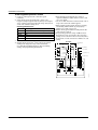
Smoke Detectors
Notes
2-Wire Smoke Detectors
1. Connect up to sixteen 2-wire smoke detectors across
zone 1 terminals 8 (+) and 9 (-) as shown in the
Summary of Connections diagram. Observe proper
polarity when connecting the detectors.
2. Connect an EOL resistor across the loop wires at the
last detector.
4-Wire Smoke Detectors
3. Connect 4-wire smoke detectors (up to 16, depending
on detector current drain) to any zone from 2-8 as
shown on the next page. This control does not
automatically reset power to 4-wire smoke detector
zones, so you must use a relay (e.g., 4204, 4229), or
on-board trigger 17 to reset power (also required for
fire verification). Do this by programming the
designated relay/trigger as zone type 54 (fire zone
reset); see On-Board Trigger section for other
information.
• Fire Verification (zone type 16): The control
panel will “verify” a fire alarm by resetting the
smoke detectors after the first alarm trigger, and
then waiting 90 seconds for a second alarm
trigger. If the smoke detector does not trigger
again, the control will disregard the first trigger,
and no alarm signal will occur. This feature
eliminates false alarms from smoke detectors
due to electrical or physical transients.
• The zone 1 alarm current supports only one
smoke detector in the alarmed state.
• Do not use 4-wire smoke detectors on zone 1.
• Maximum current for trigger 17 output for 4wire smoke detectors is 100mA.
Mounting and Wiring the Control
5
RELAY
AUX PWR
OUTPUT
TERMINALS
8
PROGRAM
RELAY
AS ZONE
TYPE 54
(FIRE ZONE
RESET)
4
BLK
+
8
N.C.
+
AUX PWR (+) 5
EOL
POWER
SUPERVISION
RELAY MODULE
A77-716B.
USE N.O.
CONTACT,
WHICH CLOSES
WHEN POWER
IS APPLIED.
VIOLET
HEAT
DETECTOR
TO ZONE TERM. ( )
4-WIRE SMOKE
OR COMBUSTION
DETECTOR
9
+
9
RED
EOL
POWER
SUPERVISION
RELAY MODULE
A77-716B.
USE N.O.
CONTACT,
WHICH CLOSES
WHEN POWER
IS APPLIED.
N.O.
VIOLET
2000
OHMS
EOLR
TO ZONE TERM. (+)
HEAT
DETECTOR
TO ZONE TERM. ( )
4-Wire Smoke Detector Using Relay for Power Reset
4-Wire Smoke Detector Using Output 17 for Power Reset
Notes
4219/4229 Expansion Zones
Connect each module to the control’s keypad terminals. • Supports up to 40 expansion zones (NO or NC)
using 4219/4229 Zone Expander Modules as
Assign each module a unique device address (07-11)
follows:
using its DIP switches. Device addresses determine
the zone numbers being used, as shown in the
• Use 1000 ohm end-of-line resistors at the end of
following table.
loops connected to the 4219/4229 modules. (Endof line resistors used on the control terminals are
Expander Module Addresses
2000 ohms.)
For Zones… Set Module to Device Address…
• Expansion zones have normal response time
09-16
07 (not available if zone-doubling enabled)
(400–500 msec), except zone connected to each
17-24
08
module’s loop “A,” which can be set for fast
25-32
09
response† (10–15 msec).
33-40
10
† Do not use fast response in Western Europe;
41-48
11
fast response is not permitted by
Connect sensors to the module’s loops.
EN50131-1/prEN50131-3.
If using relays with the 4229, connect the desired
field wiring to the unit's relay contact terminals.
RELAY
CONNECTOR
4229
RELAY
2
DIP SWITCH
FOR SETTING ADDRESS
AND ZONE "A" RESPONSE
EITHER OR BOTH CAN BE USED
RELAY
1
GRY
VIO
BLK
YEL
ORG
BRN
WHT
TAMPER JUMPER POSITION
4229 IN CABINET
(NOT TAMPER)
4229 REMOTE
(TAMPER PROTECTED)
RLY
2
RLY
1
RELAYS OFF
2
1
3
4
TB1
6
5
8
7
9
10
11
A
B
C
D
E
F
G
4
4
3
2
12
REED
(TAMPER)
SWITCH
ZONES
TERMINALS ON
CONTROL PANEL
TB2
4-PIN CONSOLE PLUG
NO C NC
NO
NC
C
GND
NO
NC
C
3.
4.
9
+
2000
OHMS
EOLR
TO ZONE TERM. (+)
1.
2.
BLK
TO OUTPUT 17 ( )
PROGRAM OUTPUT 17
FOR "OUT NORM
LOW" = YES IN 79 MENU
MODE AND AS ZONE
TYPE 54 IN
80 MENU MODE
4_wiresmk-007-V0
4-WIRE SMOKE
OR COMBUSTION
DETECTOR
9
RED
N.O.
CONTACT OPENS
MOMENTARILY UPON
FIRE ALARM RESET
8
8
Figure 7. 4-Wire Smoke Detector Connections
4_wiresmk-008-V0
+
H
1
3
2
1
GRN DATA OUT (>)
TO CONTROL
BLK
(–) GROUND
RED
(+) 12VDC
YEL DATA IN (<)
FROM
CONTROL
(TERM 6)
(TERM 4)
(TERM 5)
(TERM 7)
TERMINATE EACH
PROGRAMMED ZONE
WITH 1000 OHM (1K)
END-OF-LINE RESISTOR
(EACH ZONE'S MAX.
LOOP RESISTANCE
300 OHMS + EOL)
4229-002-V0
Figure 8. Wiring Connections, 4219 & 4229 (4229 shown)
2-7
Installation Instructions
6164 Keypad Expansion Zones
Notes
1. Connect each keypad to the control’s keypad
terminals.
2. Using the keypad’s program mode, assign each
keypad a unique keypad address (16-23), and assign a
device address (07-11) from the following chart, based
on the zone numbers being used.
• Each 6164 keypad supports up to 4 wired
expansion EOLR or double-balanced zones and
one relay output.
• Use 2000 ohm end-of-line resistors at the end of
loops connected to the 6164 keypads.
• Enter 6164 keypad program mode by pressing
and holding down both the [1] and [3] keys
within 60 seconds of power up.
• Enable the keypad addresses using data fields
*191-*196 as required.
• Program keypad zones using *56 Menu mode.
Keypad zones 1-4 correspond to the respective
groups of zones shown in the chart at left, where
keypad zone 1 is the lowest zone number in each
group.
6164 Keypad Addresses
For Zones…Set Keypad to Device Address…
09-12
07 (not available if zone-doubling enabled)
17-20
08
25-28
09
33-36
10
41-44
11
3. Connect sensors to the keypad’s zone terminals.
4. If using the keypad relay, connect the desired field
wiring to the keypad's relay contact terminals.
See 6164 Keypad Instructions for other mounting,
wiring, and programming information.
OPTIONAL
CONVENTIONAL
EOLR
DOUBLE BALANCED
2K
2K
[Y] DATA IN (<)
2K
2K
TAMPER
CONTACTS
N.O.
TAMPER
CONTACTS
[+] +12VDC IN
[-] GROUND (-12V)
N.C.
[G] DATA OUT (>)
N.O.
C.
N.C.
Z4
Z2
Z3
(Z1
&
Z2)
2-8
(Z3
&
Z4)
G
6164-005-V2
Y +
Z1
Mounting and Wiring the Control
Notes
Installing the RF Receiver
• The receiver is supervised and a trouble report is
sent (“CHECK 100” displayed) if communication
between the panel and receiver is interrupted, or
if no valid RF signals from at least one supervised
transmitter are received within 12 hours.
• Only one receiver can be installed in a system.
If the receiver is mounted remotely:
• Place the RF receiver in a high, centrally located
1. Set Device Address to “00” as described in its
area for best reception.
instructions (set all switches to the right, “off” position).
•
Do
not locate the receiver or transmitters on or
2. Mount the receiver, noting that the RF receiver can
near
metal objects. This will decrease range
detect signals from transmitters within a nominal
and/or block transmissions.
range of 67m.
• Do not locate the RF receiver in an area of high
3. Connect the receiver's wire harness to the control's
RF interference (indicated by frequent or
keypad terminals. Plug the connector at the other end
prolonged lighting of the LED in the receiver;
of the harness into the receiver. Refer to the
random flicker is OK).
installation instructions provided with the receiver
•
Do
not locate RF receiver closer than 3m from
for further installation procedures regarding antenna
any keypads to avoid interference from the
mounting, etc.
microprocessors in those units.
Use one of the following receivers:
RF Receiver
Number of Zones
5881ENL
up to 8 (including keyfob buttons)
5881ENM
up to 16 (including keyfob buttons)
5881ENH/5881EH up to 40 plus 16 keyfob buttons
5882EU/
5882EUH/5883
NOTE: CIRCUIT BOARD IS MOUNTED IN
CONTROL’S CABINET, GROUNDING LUGS (2)
PROVIDED MUST BE INSERTED IN LEFTHAND TERMINALS OF ANTENNA BLOCKS AND
SECURED TO CABINET (SEE RECEIVER’S
AND CONTROL’S INSTRUCTIONS)
ANTENNAS
CIRCUIT
BOARD
MOUNTING
HOLES
INTERFERENCE
INDICATOR
LED
=:< ;; ;; <: =
YELLOW
RED
BLACK
GREEN
5882
LOCATION
DIP SWITCH
PLUG
&
SOCKET
}
WIRING
OPENING
TO CONTROL’S
REMOTE KEYPAD
CONNECTION
POINTS.
WIRELESS ZONE NUMBERS
transmitter zones 9-48
button or transmitter zones 49-64
KNOCKOUT
AREA FOR
SURFACE
WIRING
}
TO RELEASE CIRCUIT BOARD,
REMOVE SCREWS (2)
AND BEND BACK TABS (2).
MODEL No. IS INDICATED
ON CIRCUIT BOARD
INSERT IN
RIGHT-HAND
TERMINALS
Figure 9. 5881EN RF Receiver (cover removed)
Installing a 5800TM Module
Notes
1. Mount the 5800TM next to the RF receiver (between
one and two feet from the receiver’s antennas) using
its accompanying mounting bracket. Do not install
within the control cabinet.
2. Connect the 5800TM to the control panel’s keypad
connection terminals as shown on the Summary of
Connections diagram and set to address 28.
• Use this module only in 345Hz RF systems and if
you are using one or more wireless bi-directional
keypads or keyfob; 5800TM is not necessary if
using a Transceiver (e.g., 5883).
• The 5800TM must be set to address 28 (cut redW1 jumper).
• The 5800TM can be used in partition 1 only.
• For additional information regarding the
5800TM, refer to the 5800TM’s instructions.
Installing the Transmitters
Notes
1. To be sure reception of the transmitter's signal at the
proposed mounting location is adequate, perform a
Go/No Go Test (see the Testing the System section).
2. Install transmitters in accordance with the
instructions provided with each.
3. Set 5827, 5827BD, 5804BD wireless keypads to the
programmed House ID (field *24), using its DIP
switches (5827) or follow the instructions provided
with the device.
• Refer to the table of compatible devices at the
back of this manual.
• Supervised transmitters† send check-in signals to
the receiver at 70-90 minute intervals. If at least
one check-in message is not received from each
transmitter within a 12-hour period, the “missing”
transmitter number(s) and “CHECK” is displayed.
† Hand-held transmitters (e.g., 5802, 5802CP, 5804,
5804BD, 5827, 5827BD) do not send check-in signals.
2-9
Installation Instructions
Transmitter Battery Life
• See Wireless Transmitter paragraph in the Limitations of This Alarm System statement located at the end
of this manual for information on transmitter battery life.
• Some transmitters (e.g., 5802 and 5802CP) contain long-life but non-replaceable batteries, and no battery
installation is required. At the end of their life, the complete unit must be replaced (and a new serial number
enrolled by the control).
• Button-type transmitters (such as 5801, 5802, and 5802CP) should be periodically tested for battery life.
• The 5802EU, 5802MN, 5802MN2, 5804EU, and 5804 Button Transmitters have replaceable batteries.
Do not install batteries in wireless transmitters until you are ready to enroll during system programming.
After enrolling, batteries need not be removed.
Installing a Keyswitch
Notes
1. Connect the 4146 keyswitch's normally open
momentary switch to a zone’s terminals (zones 2-8).
Remove the 2000 ohm EOL resistor if connected
across the selected zone.
2. Using a standard keypad cable as shown:
Connect the yellow and white keyswitch wires to
trigger connector pin 3 (+12V).
Connect the Red and Green LED wires to the
appropriate output 17/output 18 trigger connector
pins.
3. Connect a 2000 ohm EOL resistor across the
momentary switch.
4. You can wire an optional closed-circuit tamper switch
(model 112) in series with the zone. If the switchplate
is then removed from the wall, the tamper will open,
disabling keyswitch operation until the system is
next disarmed from the keypad.
If the tamper is opened when the system is armed, an
alarm will occur.
• Use 4146 keyswitch or any normally open
keyswitch.
• Use only one keyswitch per partition.
• If using a keyswitch in more than one partition,
you must use relays (not the on-board triggers)
for the Red/Green LED functions (step 2).
• When using a keyswitch, the zone it is connected
to is no longer available for use as a protective
zone.
• Use *56 Menu mode to program the keyswitch
zone and assign it zone type 77.
• Use *80 Menu mode to program the LED
functions: program outputs 17 and 18 for system
operation zone type 78 (red LED) and 79 (green
LED) as appropriate (see Output Device
Programming section).
8-PIN TRIGGER CONNECTOR
5
6
7
8
(GREEN)
4
OUTPUT 18
(RED)
KEY
3
+12 AUX.
OUTPUT 17 (YELLOW)
1
4-WIRE
CABLE
4146 KEYSWITCH
(ARMED)
RED
YELLOW
(READY)
GREEN
WHITE
820
ohms
820
ohms
BLACK
RED
TAMPER
SWITCH (N. C.)
BROWN
TYPICAL ZONE
ON CONTROL
BOARD
10
BROWN
LOCK
SWITCH (N. O.)
BLUE
BLUE
EOLR
(use appropriate value)
Figure 10. Keyswitch Wiring Connections
2-10
00-trigcon-004-V2
11
Mounting and Wiring the Control
Connecting Relay Modules
Notes
1. Mount either remotely or in the control panel.
2. Connect to control’s keypad terminals using the
connector harness supplied with the module. Use
standard 4-conductor twisted cable for long wiring
runs.
3. Set each module’s device address according to the
table at right.
4. Connect the desired field wiring to the unit's relay
contact terminals.
• Use 4204/4229 modules or 6164 keypad.
• Supervision: 4204/4229 modules and 6164
keypad are supervised against removal. The
module’s device address is displayed as follows if
a module is disconnected from the control’s
terminals, or if the module cover is removed and
the tamper jumper is installed:
Alpha: CHECK xx Wire Expansion
FAULT xx Wire Expansion
TAMPER xx Wire Expansion
ALARM xx Wire Expansion
Fixed-Glass: lxx (or 91 if field *199 set for 2-digit
display)
where “xx is the module’s address.
• If communication/tamper failure occurs on a
device with zones wired to it, all zones on the
device will be displayed in their respective
partitions.
Relay Module Addresses
4204/6164 † Address 4229/6164††
ON
—
ON
ON
ON
ON
ON
ON
DIP SWITCH
FOR SETTING DEVICE ADDRESS
AND ENABLING/DISABLING TAMPER
RELAY 4
TYPICAL
(SHOWN "OFF")
RELAY
3
NC
NO
C
NC
NO
C
NC
NO
RELAY
C
1
NC
fi
COVER TAMPER (REED) SWITCH
fi
4-PIN CONSOLE PLUG
C
8
fi
4204
4204
7
fi
5
ON
6
fi
4
5
2
ON
5
fi
3
4
1
—
4
2
3
0
ON
9 10 11 12
fi
ON
1
2
13
14
15
07
no. 2 (zn 17-24)
08
no. 3 (zn 25-32)
09
no. 4 (zn 33-40)
10
no. 5 (zn 41-48)
11
if using only relays with
4 2 0†
4 Use
A D D Rthese
E S S Saddresses
ETTINGS
("—" means "OFF")
the
6164 and not its zones.
3
4
5
6
7
8
9
10 11
12 13 14 15
††
Use
these
addresses
if ON
using
zone
expansion
—
ON
—
ON
—
ON
—
ON
—
—
ON
—
6164;
—
ON and
ON
—relays
—
ONwith
ON the
—
—
ON supports
ON
—
— only the
ON
— first
—
—four
— zones
ON ON in
ON parenthesis.
ON
—
—
—
—
ON ON
ON
ON
—
—
—
—
—
—
—
†††ONNot
available
if—zone
doubling
used.
SWITCH
POSITION
ON
no. 2
no. 3
no. 4
no. 1 (zn 09-16)
3
fi
12
2
fi
OFF
no. 1
Address
†††
RELAY
fi
2
EITHER OR BOTH
CAN BE USED fi
fi
13
14
15
1
TB1
16
YEL
BLK
GRN
RED
DATA IN
FROM CONTROL
s
NO
TB2
(–) GROUND
DATA OUT
TO CONTROL
(+) 12V
Figure 11. 4204 Connections to Control
(4229 Module and 6164 Keypad is shown in the Expansion Zones sections on page 2-7)
2-11
Installation Instructions
Powerline Carrier Devices
Notes
1. Install up to 16 powerline carrier devices (if no relays
are used) according to the instructions included with
each.
• When using Powerline Carrier devices, you must
use a Powerline Carrier Device Modulator. It
supplies signals from the control panel through
the premises AC mains wiring to the Powerline
Carrier devices (which are plugged into AC
outlets). You can then make devices that are
plugged into Powerline Carrier devices perform
various functions in response to commands you
enter at the security system keypads.
2. Connect the Powerline Interface Modulator (XM10E)
to the trigger pins as shown below.
3. Use Programming Mode to enter the device house ID
in data field*27, and enter the unit code using *79
Output Device menu Mode.
(BLACK)
SYNC
8
(BLUE)
7
(PURPLE)
6
COM
(GREEN)
5
DATA
GND (-)
(YELLOW)
4
OUTPUT 18
(ORANGE)
3
+12 AUX.
OUTPUT 17
(RED)
1
KEY
8-PIN TRIGGER CONNECTOR
XM10E
POWERLINE
INTERFACE
MODULATOR
1234
SA4120XM-1 CABLE
(PART OF 4120TR)
SYNC
BLK
GRN
COM
DATA
RED
MODULAR PHONE CORD (not supplied)
1 - BLACK
2 - RED
3 - GREEN
4 - YELLOW
YEL
00-trigcon-012-V0
XM10E Powerline Interface Connections
2-12
Mounting and Wiring the Control
Notes
On-Board Triggers
Connect field wiring to the desired trigger pin on the
8-pin trigger connector centrally located above the
terminal strip.
• If using a Powerline Interface Modulator and
powerline carrier devices, use the SA4120XM-1
cable (part of 4120TR Trigger Cable). See previous
Powerline Carrier Device section.
• If only using the on-board triggers, you can use a
4-wire cable (N4632-4, supplied with the control) as
shown below.
8-PIN TRIGGER CONNECTOR
(BLACK)
SYNC
8
(BLUE)
7
(PURPLE)
6
COM
(GREEN)
5
DATA
GND (-)
(YELLOW)
4
OUTPUT 18
(ORANGE)
KEY
3
+12 AUX.
OUTPUT 17
(RED)
1
SA412OXM-1
CABLE
00-trigcon-003-V1
Figure 12. On-Board Trigger Connector with
SA4120XM-1 Cable for Use With X10 Powerline Interface
Modulator
(GREEN)
OUTPUT 18
5
(BLACK)
4
GND (-)
(RED)
3
+12 AUX.
OUTPUT 17 (YELLOW)
1
KEY
8-PIN TRIGGER CONNECTOR
6
7
8
• There are two on-board triggers that can be
used to activate output devices.
• These outputs are normally high, and go low
upon programmed condition.
• The outputs can be programmed for inverted
operation (normally low, go high) using *79
Menu mode.
• Program these triggers using *80/*81 Menu
modes as you would for any other relay output.
• When using these outputs, note:
pin 1 = output number 17 (trigger 1):
15 ohms to ground when closed
(output low), open when off (output
high, normal default); can be used to
reset smoke detector power (must set
“output normal low = yes” in *79
Menu mode, and set for zone type 54,
fire zone reset, in *80 Menu mode); or
can support 12V relay module that
draws less than 100mA
pin 5 = output number 18 (trigger 2):
15 ohms to ground when closed
(output low); open when off (output
high, normal default); or can support
12V relay module that draws less than
20mA.
• NOTE: Do not exceed 120mA combined
current for both triggers. Doing so can
damage PC board components and will
void the system’s warranty.
4-WIRE
CABLE
00-trigcon-005-V2
Figure 13. On-Board Trigger Connector with
4-Wire Cable for Trigger Use Only
2-13
Installation Instructions
Phone Line Connections
Notes
Connect incoming phone line and handset wiring to the
main terminal block (via an RJ31X jack) as shown in the
Summary of Connections diagram at the back of this
manual. Wire colors represent the colors of the cable to
the RJ31X jack.
• If you are using an Audio Alarm Verification
(AAV) unit, refer to Audio Alarm Verification
(AAV) section for special wiring connections.
Alternative Communications Media (ACM)
Connections
Connect the data in/data out terminals and voltage input
terminals of the ACM to the control's keypad connection
points.
CAUTION: To reduce the risk of fire, use only
0.6mm O.D. or larger telecommunication line cord
for phone line connections.
Notes
• Use compatible ACMs (e.g., 7845i, 7845C/7835C
[in Latin America], AI4164RS, AI4164ETH).
Set the ACM’s address to “03” following the instructions
provided with the ACM.
Notes
Audio Alarm Verification Connections
(AAV, “Listen-In”)
• Set field *91 for AAV and program the appropriate
output (output 17 or 18) using *80 Menu mode
(select zone type “60”).
• For voice session monitoring, connect an EOLR
zone to UVCM module terminals 6 & 7, and
program the zone as zone type 81 (*56 Menu
mode).
E.g., Using output 18 for the trigger, program an
output function in *80 Menu mode as:
ZT = 60, P = 0, Action = 1, Device = 18
Refer to the connection diagram below.
Connections use one of the on-board triggers.
Suggested AAV Module:
ADEMCO UVS (shown) or Eagle 1250
OUTPUT 18
5
CONTROL
GND
4
10 11
TIP
RED (R)
GREEN (T)
GREY (R)
RJ31X
BROWN (T)
OPTIONAL
MONITORING ZONE
CONNECTION
(USE ZONE TYPE 81)
7
8
9
24 25
RING
TO
PREMISES
HANDSET
5
INCOMING
PHONE LINE
aav_uvcm-003-V0
2
1
3
GND
+12VDC IN
Figure 14. Connection of AAV Unit
2-14
23
4
FALLING VOICE TRIG
22
EOL
6
1 2 3 4 5 6 7 8
SWITCH BANK 2
SWITCH BANK 1
1 2 3 4 5 6 7 8
1 = ON
2 = ON
3 = OFF
4 = ON
5 = ON
6 = ON
7 = ON
8 = ON
ON
SWITCH
BANK 2
1 = OFF
2 = OFF
3 = OFF
4 = OFF
5 = OFF
6 = OFF
7 = OFF
8 = ON
ON
NOTE:
REFER TO UVCM MODULE
INSTRUCTIONS FOR
CONNECTIONS TO AUDIO
SPEAKERS AND MICROPHONE.
SWITCH
BANK 1
21
29 30 31 32 33 34
UVCM
MODULE
EARTH
GROUND
ZONE
TERMINALS
5
+12VDC
AUXILIARY
AUDIO LEVEL
ADJUSTMENT
TRIM POT
TRIGGER
CONNECTOR
S E C T I O N
3
Programming Overview
• • • • • • • • • • • • • • • • • • • • • • • • • • • • • • • • • • • • • • •
About Programming
You can program the system at any time, even at the installer's premises prior to the actual
installation. Programming can also be performed remotely from the installer’s office/home, using an
IBM compatible personal computer, a CIA/CIA-EU modem, and Compass downloading software.
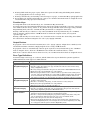
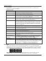
The following is a list of the various Programming modes used to program this system:
Programming Mode…
Data Field Programming
Used to …
Program basic data fields used for setting the various system options.
Most of the data fields in this system have been programmed for specific
default values. However, some fields must be programmed for each particular
installation to establish its specific alarm and reporting features.
∗56 Zone Programming
Assign zone characteristics, report codes, alpha descriptors, and serial
numbers for RF transmitters.
∗57 Function Key Programming
Program each of the four alphabet function keys to perform one of several
system operations.
∗58 Zone Programming
(Expert Mode)
Assign zone attributes similar to ∗56 mode, but provides a faster
programming procedure and is intended for those more experienced in
programming controls of this type.
∗79 Output Device Mapping
Assign device addresses used by 4229/4204 Relay modules or 6164 keypad
and map specific relays and device outputs, and assign unit codes for
Powerline Carrier devices
∗80 Output Definitions
Define up to 48 output definitions which can control the output relays
mapped using *79 Output Device Mapping mode.
∗81 Zone List Programming
Create Zone Lists for relay/powerline carrier zones, chime zones, night-stay,
exit route zones, final exit door zone, and pager zones.
∗82 Alpha Programming
Scheduling Mode (code + [#] +64)
Create alpha descriptors for easy zone identification.
Create schedules to automate various system functions or to determine user
access.
Zones and Partitions
Each protection zone needs to be programmed with various attributes using *56 Zone Programming
mode or *58 Expert Programming mode. Refer to those sections for detailed procedures.
The system can control three independent areas of protection (known as partitions) for use by
independent users, if desired, by simply assigning zones to one of the partitions during zone
programming. The system, by default, automatically distributes users among the three partitions.
The master user can change the user number distributions.
Zones can also be assigned to a common area partition if partition 3 is so designated, which is an
area shared by users of the other two partitions (such as a lobby in a building). This allows either
independent partition to arm, while leaving the common area partition disarmed for access into the
other partition. The following describes the functioning of the common area partition, if used:
• The common area sounds and reports alarms only when both the other partitions are armed. If
only one partition is armed, the system ignores faults in the common area.
• Either partition may arm its system if the common area is faulted, but once armed, the other
partition will not be able to arm unless the common area zones are first bypassed or their faults
are corrected.
• Faults in the common area are displayed on common area keypads, and will also appear on
another partition’s keypad when that partition is armed.
• Either partition can clear and restore the common area after an alarm.
3-1
Installation Instructions
Keypads
Keypads are identified by predefined addresses (starting at address 16) as follows:
Address
Keypad
Program Field
16
keypad 1
• always enabled for partition 1, all sounds enabled.
17
keypad 2
• data field *190
18
keypad 3
• data field *191
19
keypad 4
• data field *192
20
keypad 5
• data field *193
21
keypad 6
• data field *194
22
keypad 7
• data field *195
23
keypad 8
• data field *196
NOTE: First keypad is address 16.
To enable keypads:
1. Set desired address at keypad (refer to keypad’s instructions for setting the address).
2. Use data field program mode to enable keypad addresses, assign a partition, enable sound options
in fields *190-*196 as shown in the table above.
3. If desired, use data field *198 to turn on the display of the partition number.
4. Set the following keypad-related data fields as required by the installation:
*21
Quick Arm Enable
∗180 Zone Bypass Limit
*23
Forced Bypass
∗186 Display Options
∗25
Arming Prevention Override
∗188 Keypad Sabotage Options
*84
Auto STAY Arm†
∗197 Exit Time Display Interval
∗88
Exit Options
† NOTE: Do not use this option if Telecommand is installed to permit
remote end-user control of the system.
Wireless Receiver Transmitters, and Wireless Keys (keyfobs)
Receiver: Set the receiver’s address to “00” using its DIP switches, then set the following options:
*22
RF Jam Option
*24
RF House ID Code (if using DIP switch equipped wireless keypads) for each partition
∗25
Arming Prevention Override
*67
Transmitter Low Battery Report Code
*75
Transmitter Low Battery Restore Report Code
∗173 RF Reporting Options
∗178 RF Supervision/RF Jam Options
Use *56 Menu mode to program wireless zones 9-48 and wireless button zones 49-64.
Transmitters: Use *56 or *58 Zone Programming Menu modes to program zone information and
enroll transmitters (zones 9-48, buttons 49-64).
Wireless Keys: Use Wireless Key Programming Templates section of the *58 Zone Programming
Menu mode to program zone information and enroll each button of the wireless keys used. Once a
wireless key is enrolled, it must be assigned to a user before it becomes active. See Adding/Deleting
Security Codes section for procedure.
Pager Programming
The system can send various reports to up to 3 pagers.
To program pager reporting, do the following:
1. Enter the appropriate information in the following data fields:
*160, *163, *166 Pager Phone Numbers (for pagers 1-3 respectively)
*161, *164, *167 Pager Prefix Characters (for pagers 1-3 respectively)
*162, *165, *168 Pager Reporting Options by Partition† (for pagers 1-3 respectively)
2. Enable Pager Delay, if desired, in field *169 (delays alarm reporting for ALL pagers).
3. Enable appropriate user open/close pager reports using the user attribute command
(master code + [8] + user no. + [#] [5] + [1]). Users that perform actions in their assigned partition
will, if enabled, attempt to report to all pagers enabled for open/close reporting in that partition.
3-2
4. If using child-not-home pager report, define the report schedule using Scheduling mode (master
code + [#] [6] [4] then select event type “03”).
5. If using a function key to manually send a message to a pager, see Function Keys paragraph below.
6. If reporting zone alarms and troubles to a pager, use *81 Zone List menu mode to assign the zones
associated with each pager (zone lists 9-12).
Function Keys
To assign functions to the function keys, use *57 Function Key menu mode.
To assign emergency key functions (function key option “00”), first program the respective emergency
zone number (95 for “A” key, 96 for “C” key, 99 for “B” key) with the desired zone type using *56 Zone
Programming mode, then use *57 Function Key menu mode to assign the desired key.
If using a function key to activate a relay action (*57 Menu mode key function 07), use *79 Menu
mode to map the output, and use *80 Menu mode to define the output’s action; select system
operation type “66.”
If using a function key for a user macro, use *57 menu mode to activate the desired key, then define
the actual macro functions using the user code + [#] + [6] [6] command.
Output Devices
To program a device for manual activation (user code + [#] [7] / [#] [8] + 2-digit device number) or for
scheduled automatic activation, simply map the device using *79 Menu mode.
To program a device to automatically activate upon a system event (or function key), use *79 Menu
mode to map the device, then use *80 Menu mode to define the automated device action.
If the device action is based on more than one zone, use *81 Zone List menu mode to assign the zones.
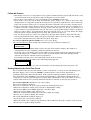
Zone Type Definitions
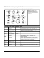
You must assign a zone type to each zone, which defines the way in which the system responds to
faults in that zone. Zone types are defined below.
Zone Type
Type 00: Zone Not Used
Type 01
Entry/Exit Burglary #1
Type 02
Entry/Exit Burglary #2
Type 03
Perimeter Burglary
Type 04
Interior Follower
Description
Program a zone with this zone type if the zone is not used.
• Assign to zones that are used for primary entry and exit.
• Provides entry delay when zone type is faulted if control is armed in the Away,
Stay, or Night-Stay modes.
• No entry delay provided when the panel is armed in the Instant/Maximum mode.
• Entry delay #1 is programmable for each partition.
• Exit delay begins whenever the control is armed, regardless of the arming mode
selected, and is programmable for each partition. (If Final Contact Set exit option
is selected in field *88, exit delay remains on indefinitely until the last zone in
zone list 8 is restored; once the last zone is restored, exit delay is then 5 seconds.)
• Assign to zones that are used for entry and exit and require more time than the
primary entry/exit point.
• Provides a secondary entry delay, in same manner as entry delay #1.
• Entry delay #2 is programmable for each partition.
• Exit delay is the same as described for Type 01.
• Assign to all sensors or contacts on windows and infrequently used exterior doors.
• Provides an instant alarm if the zone is faulted when the panel is armed in the
Away, Stay, Night-Stay, Instant or Maximum modes.
• Assign to a zone covering an area such as a foyer, lobby, or hallway through
which one must pass upon entry (to and from the keypad).
• Provides a delayed alarm (using the programmed entry 1 time) if the entry/exit
zone is faulted first. Otherwise this zone type gives an instant alarm.
• Active when the panel is armed in the Away mode.
• Bypassed automatically when the panel is armed in the Stay or Instant modes;
if armed in Night-Stay mode, zones assigned to zone list 05 (night-stay zone list)
are not bypassed when system armed in Night-Stay mode.
3-3
Installation Instructions
• Assign to a zone covering a sensitive area such as a stock room, drug supply
room, emergency exit door, etc.
• Can also be used with a sensor or contact for an area where immediate
notification of an entry is desired.
• Assign for use with sensor, device, or sounder tamper protection.
• Provides an instant alarm if faulted when armed in the Away, Stay, Night-Stay,
Instant or Maximum modes.
• During the disarmed state, the system will provide a latched trouble sounding
from the keypad (and a central station report, if desired).
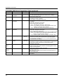
Type 06
• Usually assigned to a zone containing an emergency button.
24-hour Silent Alarm
• Sends a report to the central station but provides no keypad display or sounding.
Type 07
• Assign to a zone that has an emergency button.
24-hour Audible Alarm • Sends a report to the central station, and provides an alarm sound at the keypad,
and an audible external alarm.
Type 08
• Assign to a zone containing an emergency button, or to a zone containing
24-hour Auxiliary
monitoring devices such as water or temperature sensors.
Alarm
• Sends a report to the central station and provides an alarm sound at the keypad.
(No siren output is provided.)
Type 09
• Provides a fire alarm on short circuit and a trouble condition on open circuit. A
Supervised Fire
fire alarm produces a pulsing siren output.
• This zone type is always active and cannot be bypassed.
Type 10
• Provides entry delay (using the programmed entry time), if tripped when the
Interior w/Delay
panel is armed in the Away mode.
• Entry Delay 1 begins whenever sensors in this zone are violated, regardless of
whether or not an entry/exit delay zone was tripped first.
• Bypassed when the panel is armed in the Stay or Instant modes; if armed in
Night-Stay mode, zones assigned to zone list 05 (night-stay zone list) are not
bypassed when system armed in Night-Stay mode.
Type 12
• Works as a dynamic monitor of a zone fault/trouble (not alarm). In the case of a
Monitor Zone
short/open, the message, "*ALARM*-24 Hr. Non-Burg. -#XXX " (where XXX is the
zone number) will be sent to the Central Station. The system keypad will display
a “CHECK” message indicating the appropriate zone (but keypad beeping does
not occur). Upon restoral of the zone, the message, "*RESTORE*-24 Hr. NonBurg. -#XXX " will be sent to the Central Station.
• The “CHECK” message will automatically disappear from the keypad dynamically,
when the zone restores; a user code + off sequence is not needed to reset the zone.
• Faults of this zone type are independent of the system, and can exist at the time
of arming without interference.
• Since this is a “trouble” zone type, do not use this zone type with relays set to
activate upon “alarm.”
Type 14
• Assigned to any zone with a gas detector.
24 Hour Gas Monitor
• The siren output will pulse when this zone type is alarmed.
• Always active and cannot be bypassed.
Type 16
• Provides a fire alarm when zone is shorted, but only after alarm is verified.
Fire w/Verification
• System verifies alarm by resetting zones for 12 seconds after short is detected. A
subsequent short circuit within 90 seconds triggers fire alarm.
• Provides a trouble response when zone is open.
Type 20: Arm-Stay
• Arms the system in Stay mode when the zone is activated.
(BR RF devices only)
• Pushbutton units send user number to the central station when arming/disarming.
• User number for button must be assigned.
Type 21: Arm-Away
• Arms the system in Away mode when the zone is activated.
(BR RF devices only)
• Pushbutton units send user number to the central station when arming/disarming.
• User number for button must be assigned.
Type 22: Disarm
• Disarms the system when the zone is activated.
(BR RF devices only)
• User number for button must be assigned.
Type 23 *
• Can be used on a zone when an output relay action is desired, but with no
No Alarm Response
accompanying alarm (e.g., lobby door access).
• Zone faults/restores are event logged.
* The system can still be armed when these zone types are in a faulted condition.
Type 05
Trouble when
Disarmed/
Alarm when Armed
3-4
Type 24
Silent Burglary
Type 77
Keyswitch
Type 81
AAV Monitor Zone
Type 82
Blockschloss
Types 90-93
Configurable
• Usually assigned to all sensors or contacts on windows and infrequently used
exterior doors where siren sounding is NOT desired for alarms.
• Provides an instant alarm, with NO audible indication at any keypad or external
sounder, if the zone is faulted when the system is armed in the Away, Stay,
Instant, or Maximum modes.
• A report is sent to the central station.
• Assign to zone wired to a keyswitch.
• Do not use devices assigned as input type “BR” with this zone type.
• Assign to zone connected to AAV module.
• Monitors 2-way voice sessions as follows:
- When the zone is faulted, all alarm sounding and dialer reporting stops, except
for fire alarms, which immediately terminate the voice session and cause
a fire report to be sent.
- When the zone is restored (session ended), sounding resumes (if bell timeout
has not expired) and reports that were stopped are sent.
• Used with special blockschloss lock and key.
• System arms 5 seconds after the key is fully turned (arms MAXIMUM); key can
then be removed.
• When armed, the blockschloss zone is shorted. An open circuit on this zone causes
trouble condition.
• If zones are “not ready,” the key will not turn fully and the system will not arm.
• Contact ID report code is 409.
• Once the system is armed using blockschloss, it can be disarmed only by the key;
wired keypads, RF keypads, and keyfobs cannot be used for disarming.
• If any zone in the system is assigned as blockschloss zone type, the system will not
arm in AWAY mode. The system can, however, be armed in STAY or INSTANT
modes from keypads and keyfobs even if the blockschloss zone is faulted.
• Allows for various custom responses.
• Options include response to entry/exit delays, response to opens/shorts, types of
alarm/trouble sounding, dial delay, and unique Contact ID report codes.
• Use *83 Menu mode to program these configurable zone types.
NOTE: All of the zone types described are available for the wireless portion of the system, if used.
3-5
Installation Instructions
Mechanics of Programming
To program the system from a keypad:
• You must use a 2-line Alpha display keypad.
• All partitions must be disarmed.
Data Field Programming Procedures
Task
Procedure
Entering Program Mode
A) Press both [∗] and [#] at the same time within 50 seconds after power is applied
to the control,
OR
B) After power-up, enter [Installer code (4-1-1-2)] + 8 0 0 (long beep indicates one
of the partitions is armed and system cannot enter program mode).
(method “B” is disabled if you exit the program mode using ∗98)
Go to a Data Field
Press [∗] + [Field Number] (for example, ∗21).
A display of “EE” or “Entry Error” means you have entered a nonexistent field.
Simply re-enter [∗] plus a valid field number.
When the desired field number appears, simply enter the digits required. The
keypad beeps three times after the last digit is entered and automatically displays
the next data field in sequence.
If entering less than the maximum digits available (e.g., phone number field),
enter the desired digits, then press [∗] to end the entry.
Press [#] + [Field Number].
That field’s data is displayed, but no changes can be made.
Entering Data
Review a Data Field
Press [∗] + [Field No.] + [∗] (applies only to phone number, account number, and
pager character fields).
Deleting an Entry
Interactive Mode Programming (∗
∗56, ∗ 57, ∗58, ∗ 79, ∗80, ∗ 81, ∗82, ∗83)
Entering Interactive Mode
Press [∗] + [Interactive Mode No.] (for example, ∗56) while in Program Mode.
The Alpha display keypad will display the first of a series of prompts
requesting entries.
After making the appropriate entry, press the [∗] key to accept the entry and
continue to the next prompt.
Loading Factory Defaults/Initializing for Download
To Load Default Entries
Press ∗97 while in Program Mode. This resets all data fields to the default
values shown on the Program Form. Use ∗97 only if you wish to return to the
original factory-programmed defaults.
To Initialize Download ID
Press ∗96 while in Program Mode. This initializes the system for
downloading and resets all the subscriber account numbers and CSID.
>
Do not press 97 to load defaults if any programming has been done previously—data already
programmed into the system will be changed!
Exiting the Programming Mode
Prevent installer code reentry
Allow installer code reentry
3-6
Press ∗98. Exits Programming Mode and prevents re-entry by:
Installer Code + [8] + [0] + [0]. To enter the programming mode if ∗ 98 was
used to exit, you must first power the system down. Then power up again,
and press [∗] and [#] at the same time, within 50 seconds of powering up.
Press ∗99. Exits Programming Mode and allows re-entry by:
Installer Code + [ 8] + [0] + [0] or by: Pressing [∗] and [#] at the same time,
within 50 seconds of power-up.
Table of Device Addresses
This Device
Uses Address
RF Receiver
00
Alternative Communication
03
Media (ACM) †
Telecommand Voice Module
17-23
Zone Expanders** (4219/4229):
module 1 (zones 09 - 16)
07
module 2 (for zones 17 - 24)
08
module 3 (for zones 25 - 32)
09
module 4 (zones 33 - 40)
10
module 5 (zones 41 - 48)
11
Relay Modules (4204/6164):
module 1/6164 relay only
12
module 2/6164 relay only
13
module 3/6164 relay only
14
module 4/6164 relay only
15
Keypads:
keypad 1
16
keypad 2
17
keypad 3
18
keypad 4
19
keypad 5
20
keypad 6
21
keypad 7
22
keypad 8
23
5800TM Module
28
Reports as††
100
103
117-123
107
108
109
110
111
112
113
114
115
116
117
118
119
120
121
122
123
n/a
Enabled By…
*56 zone programming: input device type entry
automatic if output to ACM field *29 enabled
same as keypad enables; see below
*56 zone programming: input device type entry, then:
automatic if zone no. 9-16 entered as AW type or relay assigned
automatic if zone no. 17-24 entered as AW type or relay assigned
automatic if zone no. 25-32 entered as AW type or relay assigned
automatic if zone no. 33-40 entered as AW type or relay assigned
automatic if zone no. 41-48 entered as AW type or relay assigned
*79 output device programming: device address prompt:
entered at device address prompt
entered at device address prompt
entered at device address prompt
entered at device address prompt
data field programming as listed below:
always enabled for partition 1, all sounds enabled.
data field *190
data field *191
data field *192
data field *193
data field *194
data field *195
data field *196
automatic
† ACM devices include: 7845i Ethernet Interface Internet/Intranet, AI4164RS/AI4164ETH RS485/Ethernet Eureka Network
Interface
†† Addressable devices are identified by “1” plus the device address when reporting. Enter a report code for zone 91 to enable
addressable device reporting (default = reports enabled). See field *199 for addressable device (ECP) 3-digit/2-digit
identification keypad display options.
** or 6164 Keypad using zones; address 07 = zones 9-12, 08 = zones 17-20, 09 = zones 25-28, 10 = zones 33-36, 11 = zones 41-44
3-7
Installation Instructions
3-8
S E C T I O N
4
Data Field Programming
• • • • • • • • • • • • • • • • • • • • • • • • • • • • • • • • • • • • • • •
About Data Field Programming
The following pages list this control’s data fields in numerical order. Field numbers are listed in the
left column followed by a “Title and Data Entries” column, which lists the valid entries for each field.
Experienced installers can simply follow this column when programming the data fields. The
“Explanation” column provides explanatory information and special notes where applicable.
Use the blank programming form to record the data for this installation.
Programming Data Fields
Data field programming involves making the appropriate entries for each of the data fields.
Start Data Field programming by entering the installer code + 8 + 0 + 0.
System Setup Fields
FIELD
TITLE and DATA ENTRIES
EXPLANATION
*20
Installer Code
The Installer Code is used to assign the 4-digit Master Security Code.
See "Master Code" in the System Operation section for procedure.
*21
*22
Enter 4 digits, 0-9
Quick Arm Enable
0 = do not allow quick arm
1 = allow quick arm
RF Options
Entry 1 - Jam detection
0 = no RF Jam detection; 1 = detect RF Jam*
Entry 2 – supervision interval
0 = 12 hours; 1 = 2 hours; 2 = 20 minutes
when disarmed/ 2 hours when armed
3 = 12 hrs for burg zones/ 3 hrs for fire zones
*23
Quick (Forced) Bypass
*24
RF House ID Code
*25
*26
0 = no quick bypass
1 = allow quick bypass (code + [6] + [#] )
00 = disable all wireless keypad usage
01–31 = House ID for partition 1, 2, 3
Arming Prevention Override
Entry 1: 0 = no arming prevention override
1 = allow system to arm with an RF
supervision failure
2 = allow system to be armed with
an AC Mains Loss
4 = allow system to be armed with a
system low battery
Entry 2: 0 = no tamper override***
1† = allow system to be armed with
a tamper fault
2† = allow system to be armed with
a tamper fault once
Chime By Zone List 3
0 = no zone list (chimes on fault of any
entry/exit or perimeter zone when chime
mode on)
1 = use zone list (chimes on fault of
specific zones programmed in zone list
3 when Chime mode on)
If enabled, a user code is not needed to arm the system. Instead,
users can press the [#] followed by an arming key to arm the system.
However, the user code is always needed to disarm the system.
If jam detection enabled, a report is sent if the system detects an RF
jamming signal. See field *178 for other jam/supervision options.
When using RF Receivers with 5800 series transmitters, entry 2
should be 0 or 3.
* Must be selected for prEN50131-5-3 Class 2 compliance.
All zones bypassed by this function will be displayed after the bypass
is initiated.
The House ID identifies receivers and wireless keypads. If a 5827 or
5827BD wireless keypad or 5804BD/5804BDV transmitter is being
used, a House ID code must be entered, and the keypad must be set
to the same House ID. You can assign RF house ID for each partition.
Does not apply to 5839 or 5828/5828V.
If no override is selected, systems will not be able to be armed when
there is either a supervision failure, system low battery, AC mains
loss, or a tamper condition.
If override is enabled, the user must enter the arming sequence twice
to arm the system; the first entry of user code + arm command will
not arm, but a second entry of user code +arm command will arm the
system.
E.g., To select arm with “supervision failure” and “low battery”, enter
5 (1 + 4)
† NOTE: If tamper option 1 or 2 is selected, field *175 digit 2 must
be “0.”
*** Must be 0 for prEN50131-3 compliance
If enabled, you can define the specific zones intended to chime when
faulted while the system is in Chime mode. Use zone list 3 to assign
these zones (see ∗81 Zone List Programming section for details).
4-1
Installation Instructions
FIELD
TITLE and DATA ENTRIES
EXPLANATION
*27
Powerline Carrier Device (X-10)
House ID
Powerline Carrier devices require a House ID, identified in this field.
Program Powerline Carrier devices in interactive modes ∗79, *80 and
*81.
0=A
1=B
2=C
3=D
4=E
5=F
*28
*29
*30
6=G
7=H
8=I
9=J
# + 10 = K
# + 11 = L
# + 12 = M
# + 13 = N
# + 14 = O
# + 15 = P
Select the desired keypad display language.
Language Select
0 = English
1 = Spanish
2 = Italian
3 = Portuguese
ECP Contact ID Output for ACM
0 = not used
1 = use Contact ID output on ECP
Make Partition 3 a Common Area
Partition
If selected, all messages programmed to go to the primary telephone
line receiver will also be sent (in Contact ID format) to the connected
Alternative Communication Media (ACM), such as a 7845i
Internet/Intranet Communicator or AI4164RS/AI4164ETH Eureka
Network Interface, or 7845C/7835C cellular radio (in selected
countries). The data line is supervised as well as certain functions in
a long range radio. If communication is lost or a trouble develops, an
attempt will be made to send a message via both ACM and telephone
to the central station.
Program the ACM for device address 3.
If selected, partition 3 functions as a common area partition, rather
than as an independent partition.
0 = no (must be 0 if system uses zone type
82 - Blockschloss)
1 = yes, make partition 3 a common area
partition
Zone Sounds & Timing
FIELD
*31
*32
EXPLANATION
Single Alarm Sounding Per Zone
Select whether a zone going into alarm should sound more than once
per armed period.
(per armed period)
0 = no limit on alarm sounding per zone
1 = limit alarm sounding to once per arming
period for a given zone
Fire Alarm Sounder Timeout
0 = yes; fire sounder timeout after time
programmed in field ∗33
1 = no fire sounder timeout; continue
sounding until manually turned off
*33
Siren Timeout
*34
Exit Delay
*35
Entry Delay 1
*36
Entry Delay 2
*37
4-2
TITLE and DATA ENTRIES
0 = No timeout
1 = 1 min
2 = 2 min
3 = 3 min
4 = 4 min
5 = 8 min
6 = 16 min
00 - 96 = 0 - 96 seconds
97 = 120 seconds
00 - 96 = 0 - 96 seconds
97 = 120 seconds
98 = 180 seconds
99 = 240 seconds
Select whether fire alarm sounding expires after sounder timeout or
remains until manually turned off.
This field determines whether the external sounder will shut off after
time allotted, or continue until manually turned off.
The system waits the time entered before arming entry/exit zones. If
the entry/exit door is left open after this time expires, an alarm will
occur or the zone will be auto-bypassed, depending on the selection in
field *88. Common area zones use same delay as partition 1.
Upon entering, the system must be disarmed before the time entered
expires, otherwise it sounds an alarm. Common area zones use same
delay as partition 1.
See *35 for explanation.
See *35 above for entries.
Audible Exit Warning
0 = no; 1 = yes
Warning sound consists of slow continuous beeps until last 10 seconds,
then it changes to fast beeps. Sound ends when exit time expires.
*38
*39
Confirmation Of Arming Ding
Entry 1: 0 = no; 1 = yes, 1-second ding
(ding if armed from wired keypad)
Entry 2: Enter 0-15 from table below.
(ding if armed from RF device)
Entry
Ding at Siren Trigger 2 Output
0
none
none
1
none
250mS
2
3
none
none
1 second
4 seconds
4
250mS
none
5
250mS
250mS
6
250mS
1 second
7
8
250mS
1 second
4 seconds
none
9
1 second
250mS
#+10
1 second
1 second
#+11
1 second
4 seconds
#+12
4 seconds
none
#+13
#+14
4 seconds
4 seconds
250mS
1 second
#+15
4 seconds
4 seconds
Power-Up In Previous State
0 = always power-up in a disarmed state
1 = assume the system status prior to
power down
Entry 1 for each partition selects whether arming from wired
keypads causes siren ding. Confirmation of arming is 1/2 second
external sounder “ding.” Ding occurs when closing reports is sent, or
when exit delay expires.
Entry 2 for each partition selects whether arming from remote RF
devices causes siren ding and/or activates trigger 2 output; also selects
siren ding/trigger activation duration (arm = 2 dings of selected
duration with 1 second off between; disarm = 1 ding of selected
duration). Ding occurs upon reception of the wireless arming command.
NOTE: If using an option that activates trigger 2, trigger 2 must be
dedicated to only this function; do not assign any other functions to
trigger 2.
When the system powers up armed, an alarm will occur 1 minute
after arming if a zone is faulted at that time.
Note that if the previous state was armed AWAY or STAY, the
system will not respond to sensor changes for 1 minute, which allows
time for sensors such as PIRs to stabilize.
Dialer Programming (∗ 40 – ∗50)
FIELD
TITLE and DATA ENTRIES
EXPLANATION
*40
PABX Access Code
To clear entries from field, press ∗40∗. If fewer than 6 digits need to
be entered, exit by pressing [∗], which advances to the next field.
*41
*42
*43
*44
Enter up to 6 digits if PABX is needed to
access an outside line. Do not fill unused
spaces.
0–9, # + 11 for ‘∗’, # + 12 for ‘#’, # + 13 for a
pause (2 seconds)
Primary Phone No.
Enter up to 20 digits. Do not fill unused
spaces.
0–9, # + 11 for ‘∗’, # + 12 for ‘#’, # + 13 for a
pause (2 seconds)
Secondary Phone No.
Enter up to 20 digits.
0–9, # + 11 for ‘✱’, # + 12 for ‘#’, # + 13 for a
pause (2 seconds)
Part. 1 Primary Subs. Acct. No.
Enter digits 0–9; # + 11 for B, # + 12 for C, #
+ 13 for D, # + 14 for E, # + 15 for F.
Part. 1 Secondary Subs. Acct.
No.
Call Waiting: If the subscriber’s phone service has “call waiting”
(and is not using PABX), enter “*70” (“# + 11”) plus “# + 13” (pause)
as the PABX entry to disable “call waiting” during control panel calls.
If the subscriber does not have “call waiting” and is not using PABX,
make no entry in this field.
If you enter fewer than 20 digits, exit by pressing [∗]. To clear entries
from field, press ∗41∗.
NOTE: Backup reporting (in which 8 calls are made to the secondary
phone number if no kissoff is received after 8 attempts to the primary
number) is automatic only if there is a secondary phone number (field
∗42).
If you enter fewer than 20 digits, exit by pressing [∗]. To clear entries
from field, press ∗42∗. See backup reporting note for field ∗41.
Don’t fill unused spaces.
Enter up to 10 digits, depending on the report format selected in field
*48. To clear entries from field, press ∗43∗.
Enter up to 10 digits, depending on the report format selected in field
*48. To clear entries from field, press ∗44∗.
Enter digits 0–9; # + 11 for B, # + 12 for C, #
+ 13 for D, # + 14 for E, # + 15 for F.
*45
*46
Part. 2 Primary Subs. Acct. No.
Enter digits 0–9; # + 11 for B, # + 12 for C, #
+ 13 for D, # + 14 for E, # + 15 for F.
Part. 2 Secondary Subs. Acct. No.
Enter digits 0–9; # + 11 for B, # + 12 for C, #
+ 13 for D, # + 14 for E, # + 15 for F.
Enter up to 10 digits, depending on the report format selected in field
*48. To clear entries from field, press ∗45∗.
Enter up to 10 digits, depending on the report format selected in field
*48. To clear entries from field, press ∗46∗.
4-3
Installation Instructions
FIELD
TITLE and DATA ENTRIES
EXPLANATION
*47
Phone System Select
Select the type of telephone service.
*48
*49
*50
*51
*52
*53
4-4
If Central Station Receiver is not on satellite
link: 0 = Decadic Pulse Dial; 1 =
Multifrequency Tone Dial
If Central Station Receiver is on satellite link:
2 = Decadic Pulse Dial;
3 = Multifrequency Tone Dial
Report Format (Primary/Secondary)
0 = 3+1, 4+1 ADEMCO L/S STANDARD
1 = 3+1, 4+1 RADIONICS STANDARD
2 = 4+2 ADEMCO L/S STANDARD
3 = 4+2 RADIONICS STANDARD
5 = CID* using 10-digit account number
6 = 4+2 ADEMCO EXPRESS
7 = CID* using 4-digit account number
8 = 3+1, 4+1 ADEMCO L/S EXPANDED
9 = 3+1, 4+1 RADIONICS EXPANDED
10 = ROBOFON 8 (6-digit account number)
11 = ROBOFON Contact ID
Split/Dual Reporting
Select report format for primary and secondary phone numbers.
* ADEMCO Contact ID format
NOTE: To enable the audio “beeps” format (Follow-Me feature), refer
to the System Features section later in this manual, and the User
Guide.
To Primary No.
alarms, restore, cancel
all except open/close, test
alarms, restore, cancel
all except open/close, test
all
To Secondary No.
others
open/close, test
all
all
all
0 = disable (standard/backup report only).
1 - 5 (see table to right)
1=
2=
3=
4=
5=
Burglary Dialer Delay
Provides delay of “BURGLARY ALARM” report to the central station,
which allows time for the subscriber to avoid a false alarm
transmission. This delay does not apply to zone type 24 alarms (silent
burglary) or to 24-hour zone types 6, 7, and 8 (silent panic, audible
alarm, auxiliary alarm), which are always sent as soon as they occur.
0 = no
1 = 15
2 = 30
3 = 45
dial delay
seconds
seconds
seconds
Part. 3 Primary Subs. Acct. No.
Enter digits 0–9; # + 11 for B, # + 12 for C, #
+ 13 for D, # + 14 for E, # + 15 for F.
Part. 3 Secondary Subs. Acct. No.
Enter digits 0–9; # + 11 for B, # + 12 for C, #
+ 13 for D, # + 14 for E, # + 15 for F.
SESCOA/Radionics Select
0 = Radionics (0-9, B-F reporting)
1 = SESCOA (0-9 only reporting)
*54
Dynamic Signaling Delay
*55
Dynamic Signaling Priority
0 = disabled (both signals sent)
1–15 = entry times a 15-second delay.
e.g., 1 = 15 seconds, 2 = 30 seconds, etc.
0 = Primary dialer first;
1 = ECP Contact ID output first.
Enter up to 10 digits, depending on the report format selected in field
*48.
Enter up to 10 digits, depending on the report format selected in field
*48.
Select SESCOA or Radionics format.
Select 0 for all other formats.
Intended for use with ECP Contact ID Output reporting via ACM.
This field lets you select the time the panel should wait for
acknowledgment from the first reporting destination (see ∗55) before
it attempts to send a message to the second destination. Delays can
be selected from 0 to 225 seconds, in 15-second increments. This delay
is per message. If ”0” is entered in this field, the control panel will
send redundant reports to both Primary Dialer and ECP output.
Intended for use with Alternative Communication Media reporting.
You must also enable field ∗29, ECP Contact ID Output for ACM.
Select the initial reporting destination for messages as follows:
Primary Dialer First selected (0):
• If acknowledged before delay expires (see ∗54), then message will
not be sent to ECP output.
• If not acknowledged before delay expires, then message is sent to
both the Primary Phone No. and ECP output.
ECP Contact ID Output First selected (1):
• If acknowledged before delay expires, then message will not be sent
to the primary dialer.
• If not acknowledged before delay expires, then message is sent to
both the Primary Phone No. and ECP Contact ID output.
System Status Report Codes
Zone report codes are programmed using interactive •56 or •58 Zone Programming modes, while system status
(non-alarm) codes and restore codes are entered in the following data fields. The actual report code digits that
you enter depend upon the particular installation, and should agree with the Central Station office receiving the
signals.
To disable a report code, enter “0” in the first entry.
3+1, 4+1 Standard or Robofon 8 Format: Enter a code in the first entry: 1–9, A, B, C, D, E, or F. Enter #+10
for A (this reports a “0” on some receivers), #+11 for B, #+12 for C, #+13 for D, #+14 for E, #+15 for F.
Entering 0 in the second box advances to the next field.
Expanded or 4+2 Format: Enter codes in both entries (first and second digits) for 1–9 or A–F, as described
above. An entry of “0” in the second entry eliminates the expanded message for that report.
ADEMCO or Robofon Contact ID® Reporting: Enter a digit in the first entry to enable the zone to report.
Use a different digit for each zone until you have used up available digits. If the number of zones exceeds the
number of available digits, begin with digit 1 again. This is an “enabling” code only and is not the actual code
sent to the Central Station office. Entries in the second entry pair are ignored. An entry of 0 in the first box
disables the report.
FIELD
TITLE and DATA ENTRIES
EXPLANATION
*59
Exit Error Report Code
After arming the system, zones remaining open after exit delay expires
cause an alarm sound at the keypad and external sounder (keypad also
displays “EXIT ALARM”), and entry delay begins. Disarming before
the end of the entry delay stops the alarm sounding and no message is
sent to the central station. The keypad will display “CA” (fixed-word) or
“CANCELED ALARM” (alpha display).
0 = no report
1-F = report code; see description above
If the system is not disarmed before entry delay expires, an “EXIT
ALARM” message will be sent to the central station if Exit Error
Report Code is enabled. The keypad will display “EA” (fixed-word ) or
“EXIT ALARM” (alpha display), and alarm sounding continues until
the system is disarmed (or timeout occurs).
An Exit Alarm condition will also result if a fault occurs in an exit or
interior zone within 2 minutes following the end of the exit delay, and
an “EXIT ALARM” message will be sent to the central station
With Contact ID format, the message will contain the zone number
and error code 374 (“ALARM–EXIT ERROR”).
Sent if a zone has a trouble condition.
*60
Trouble Report Code
*61
Bypass Report Code
*62
AC Mains Loss Report Code
0 = disable; 1-F = see description above ∗59
Timing of this report is random with up to a 1-hour delay. If AC mains
restores before the report goes out, there is no “AC RESTORE” report.
*63
Low Battery Report Code
Sent when a low-battery condition exists in the system’s battery.
*64
Test Report Code
0 = disable; 1-F = see description above ∗59
Sent periodically to test that the communicator and phone lines are
operational. Frequency of report is set in Scheduling mode (event 11).
*65
Open Report Code
Sent upon disarming of the system in the selected partitions.
*66
Arm Away/Stay Report Code
0 = disable; 1-F = see description above ∗59
This option allows for independent programming of Away and Stay
reports for each partition.
NOTE: “OPEN” reports are not sent if the associated closing report is
not enabled.
*67
RF Low Battery Report Code
Sent when a wireless transmitter low-battery condition exists.
*68
Cancel Report Code
0 = disable; 1-F = see description above ∗59
0 = disable; 1-F = see description above ∗59
Sent when a zone is manually bypassed or is automatically bypassed
at the end of exit delay.
0 = disable; 1-F = see description above ∗59
0 = disable; 1-F = see description above ∗59
0 = disable; 1-F = see description above ∗59
0 = disable; 1-F = see description above ∗59
Sent upon disarming of the system after an alarm condition was
reported.
4-5
Installation Instructions
*69
Alarm restore message will be sent upon condition selected.
Alarm Restores
Send restore code (if fault cleared):
0 = at siren timeout (if restored) or at disarm
(whether restored or not)
1 = dynamically as the fault clears
2 = only after a disarm
0 = disable; 1-F = see description above ∗59
Sent when an alarm zone is restored to its non-faulted condition or at
the times selected in field *69.
*71
Trouble Restore Report Code
Sent when a trouble in a zone is restored
*72
Bypass Restore Report Code
0 = disable; 1-F = see description above ∗59
Sent when a zone that has been bypassed is unbypassed, either
manually or when the partition/system is disarmed.
*73
AC Mains Restore Report Code
Sent when AC mains has been restored after an AC mains outage.
*74
Low Battery Restore Report Code
*75
RF Low Battery Restore Code
0 = disable; 1-F = see description above ∗59
Sent when a transmitter’s low battery condition is restored (i.e., new
battery installed).
*76
Test Restore Report Code
Sent when the Test mode is exited.
*70
Alarm Restore Report Code
0 = disable; 1-F = see description above ∗59
0 = disable; 1-F = see description above ∗59
Sent when a system low-battery condition is restored to normal.
0 = disable; 1-F = see description above ∗59
0 = disable; 1-F = see description above ∗59
Miscellaneous System Fields
FIELD
TITLE and DATA ENTRIES
EXPLANATION
*77
Summer Time
Start/End Month
Enter the start and end month for summer time, if applicable to the
region.
0 = Disabled
1 = Jan
2 = Feb
3 = Mar
*78
4 = April
# + 10 = Oct
# + 11 = Nov
# + 12 = Dec
0 = disabled
1 = first
2 = second
3 = third
*84
Enter the start and end weekend for summer time, if applicable to
the region.
Summer Time
Start/End Weekend
4 = fourth
5 = last
6 = next to last
7 = third to last
Auto-Stay Arm
0 = no
1 = partition 1 only
2 = partition 2 only
4 = partition 3 only
Add values for multiple partitions (e.g. for
partitions 1 and 2, enter 3).
If enabled, the system will automatically change AWAY or
MAXIMUM modes to STAY and INSTANT modes respectively if the
entry/exit door is not opened and closed within the exit delay time
after a user arms in AWAY mode from a wired keypad (non-RF
device). An Opening report followed by an Armed Stay report is sent
to the Central Station.
If the door is opened and closed within the exit delay period, the
system remains in AWAY or MAXIMUM mode.
Any RF device that arms the system AWAY overrides this feature
and the system remains armed in the AWAY mode.
NOTE: Must not be used if TeleCommand is used.
Does not apply if:
• Final Contact Set exit option (field *88, option 3) is enabled.
• Blockschloss is being used.
*85
4-6
Linked Zone Verification Timer
0 = 15 secs
1 = 30 secs
2 = 45 secs
3 = 60 secs
4 = 90 secs
5 = 2 min
6 = 2-1/2 min
7 = 3 min
8 = 4 min
9 = 5 min
#+10 = 6 min
#+11 = 7 min
#+12 =
#+13 =
#+14 =
#+15 =
8 min
10 min
12 min
15 min
Sets the maximum amount of time in which two linked zones must be
tripped in an armed system to send an alarm message to the Central
Station. If only one linked zone is tripped during this time, a trouble
message (CID code 380) for that zone is sent to the Central Station.
Assign linked zone pairs in zone list 4.
FIELD
TITLE and DATA ENTRIES
EXPLANATION
*86
Cancel Verify Keypad Display
When enabled (1 = yes), this feature causes a “CANCELED
ALARM” display on the LCD keypad under the following conditions:
• After the kissoff of the cancel message to the Central Station,
indicating a successful transmission.
• When an alarm is successfully canceled before the Central Station
received the Alarm message. E.g., if an alarm is falsely triggered
and the user presses code + OFF before the dial delay time has
expired, the message will never go out to the CS.
• When the Cancel report is not enabled and the system is disarmed:
a. before dialer delay expires (alarm report not sent) message
“Canceled Alarm” is displayed.
b. after dialer delay expires message “Canceled Alarm” is not
displayed.
*87
Misc. Fault Delay Time
*88
Exit Options
*89
*90
*91
0 = no
1 = yes
0 = 15 secs
1 = 30 secs
2 = 45 secs
3 = 60 secs
4 = 90 secs
5 = 2 min
6 = 2-1/2 min
7 = 3 min
8 = 4 min
9 = 5 min
#+10 = 6 min
#+11 = 7 min
#+12 =
#+13 =
#+14 =
#+15 =
8 min
10 min
12 min
15 min
0 = all intrusion zones must be intact before
arming
1 = All intrusion zones except in exit path
(zone list 12) must be intact before
arming. Will go into alarm if not restored
at end of exit time
2 = All intrusion zones except in exit path
(zone list 12) must be intact before
arming. Will be bypassed if not restored
at end of exit time
3 = Final contact set: All intrusion zones
except in exit path (zone list 12) must
be intact before arming. Once armed,
exit delay remains on indefinitely until
the last zone, as defined in zone list 8,
is restored; then there is 5-second exit
delay before arming state is active
Event Log Full Report Code
0 = disable; 1-F = see description above ∗59
Event Log Enables
0=
1=
2=
4=
8=
x=
no event logging
log Alarm/Alarm Restore
log Trouble/Trouble Restore
log Bypass/Bypass Restore
log Open/Close
log combination of events (add value of
entries)
Used with zones assigned to a configurable zone type with fault delay
on (selected in alarm/trouble processing prompt), and sets a zone
response time of 15 seconds to 15 min. It can be assigned to zones
with sensors that provide a trouble indication when an oil or gas tank
is low, or similar applications for critical condition monitoring where
a non-alarm response is desired and where the zone response time
should be very long to avoid reacting to normal transient faults.
Select the desired option.
NOTE: Must be “0” if system uses zone type 82 - blockschloss.
If an Event Logging selection is made in field ∗90, a message can be
sent to the central station receiver when the log is 80% full. If the log
becomes full, new messages overwrite the oldest messages in the log.
This system has the ability to record up to 250 events in a history log.
At any time, the downloader operator can then upload the log and
view or print out all or selected categories of the log. The downloader
operator can also clear the log. Event log can also be viewed at an
alpha keypad (see User Guide for log display format).
The display/printout at the central station will show the date, time,
event, and description of the occurrences.
Data Entry Example: To select Alarm/Alarm Restore” and
“Open/Close”, enter 9 (1+ 8); to select all events, enter #15.
Option Selection
Select the desired options by adding the values of each desired option.
0 = none
4 = using Audio Alarm Verification (AAV) unit
8 = Enable Exit delay restart/reset ††
††“Exit Delay Restart/reset” option allows use of the [∗] key to restart
the exit delay at any time when the system is armed STAY or
INSTANT. This feature also enables automatic exit delay reset,
which resets exit delay if the entry/exit door is re-opened and closed
before exit delay time expires after arming AWAY or MAXIMUM.
Multiple choice example: for both AAV and
Exit delay restart, enter # + 12 (4 + 8).
IMPORTANT: AAV should not be used when Paging or Alarm
Reports are sent to a secondary number unless the monitoring zone
option is used (which pauses calls). Otherwise, the call to the
secondary number by the communicator after the alarm report will
prevent the AAV from taking control of the telephone line, and the
AAV “Listen in” session cannot take place.
4-7
Installation Instructions
FIELD
TITLE and DATA ENTRIES
EXPLANATION
*92
Telecom Monitor Enable
Entry 1: Sets the length of time a phone line fault must remain after
detected before the second digit option is activated.
Entry 1–Timeout:
0 = disabled
1-15 = 1 minute to 15 minutes respectively
(2 = 2 min, 3 = 3 min, etc.; # + 10 =10 min, #
+ 11 = 11 min, # + 12 = 12 min, # + 13 = 13
min, # + 14 = 14 min, # + 15 = 15 min)
Entry 2–Display/Sound:
0 = keypad display only when phone line is
faulted.
1 = keypad display plus keypad trouble
sound when line is faulted. Each
partition turns off its own trouble sound.
No automatic timeout.
2 = Same as “1” plus programmed output
device STARTS. If any partition is
armed, external sounder activates.
External sounder will be turned off by
normal siren timeout or by security code
plus OFF from any partition (it does not
have to be the one that was armed).
*93
No. of Reports In Armed Period
per Zone (Intermittent Sensor
Suppression)
Entry 2: Selects the desired phone line fault response.
Option 2 may be used even if a relay unit or Powerline carrier device
is not connected to the control.
Programmed Output Device must either be programmed to be
STOPPED in field ∗80 or STOPPED by entry of [security code] + [#] +
8 + device number. Partition in ∗80 should be set to “0,” for STOP.
This option can be used to limit the number of alarm/alarm restore
messages per zone sent to the central station in an armed period.
0 = unlimited number of reports
1 = 1 report pair per zone per armed period
2 = 2 report pairs per zone per armed period
*94
*95
Download Phone Number
Enter up to 20 digits as follows: 0–9, # +11
for “∗”, # + 12 for “#”, # + 13 for a pause.
Ring Count For Downloading
0 = Disable Monitoring Station initiated
downloading
1–14 = number of rings before control
answers incoming call
#+15 = Answering machine/fax defeat
Enter the phone number of the downloading computer.
Do not fill unused spaces. End field by entering ∗. To clear entries
from field, press ∗94∗.
Refer to the chart below and program this field accordingly.
phone
answer/fax downmodule machine
loading
Set field ∗95 to…
yes
no
no
1-14 (not 0)
yes
yes
no
higher than number of rings set on
answer/fax machine (e.g., if ans/fax
machine is 4 rings, set this field to
5). This allows access via the
phone module if the answer/fax
machine is turned off.
yes
no
yes
1-14 (not 0)
yes
yes
yes
15 (bypasses answer/fax
machine†)
no
no
no
0
no
yes
no
0
no
no
yes
1-14
no
yes
yes
15
† NOTE: If “15” is entered to bypass an answering machine and a
TeleCommand Phone Module is included in the system, you should
note the following:
When calling in from an off-premises phone, the user should make the
initial call, allow 1 or 2 rings only, then hang up, then call again. The
phone module will now seize the line, and 2 long tones sound,
followed by the usual voice prompt for the access code. If this
procedure is not followed, phone module operation will not be possible.
4-8
Pager Programming Fields
FIELD
TITLE and DATA ENTRIES
EXPLANATION
*160
Pager 1 Phone No.
If you enter fewer than 20 digits, exit by pressing [∗] and next field
number. To clear entries from this field, press ∗160∗.
*161
Pager 1 Characters
Enter up to 20 digits
Enter up to 16 characters
Up to 16 optional characters may be sent as a prefix to the 7-digit
system status code sent to pager #1 (if used). Phone number in field
*160 must have been entered. If fewer than 16 characters, exit by
pressing [∗] and next field number. To clear entries from this field,
press ∗161∗.
For example, use these optional 16 characters for the following:
• PIN number (to identify a specific pager to the paging company)
•
•
•
•
Subscriber account number
∗ (enter # + 11 to send ∗); # (enter # + 12 to send #)
Pause (enter # + 13 to allow a 2-second pause)*
Any special character(s) the end user may decide to transmit
* Some paging systems require pause(s) before the prefix.
The format for the 7-digit system status code is defined as follows:
Pager Format: XXX-YYYY where:
XXX
= 3-digit event code: 911 = Alarm
811 = Trouble
101 = Opening (disarm)
102 = Closing (arm)
YYYY
= 4-digit user or zone number (depending on type of event).
The first digit indicates partition, followed by 0, then the
2-digit user or zone number.
Example 1. Pager displays: 9 1 1 – 1 0 0 4
This indicates that the system is reporting an alarm (911) caused by a
fault in zone 4 in partition 1.
Example 2. Pager displays: 1 0 2 – 2 0 0 5
This indicates that the system is reporting a closing–system arming
(102) by User 5 in partition 2.
Pager 1 Report Options
Enter the types of reports to be sent to pager 1 for each partition.
0 = No reports sent
1 = Open/close for all users enabled to page†
4 = All alarms and troubles
5 = All alarms, troubles, and open/close for
all users enabled to page
12 = Alarms and troubles for zones entered
in zone list 9
13 = Alarms and troubles for zones listed in
zone list 9 and opens/closes for all
users enabled to page
† Reports to pager only when arming (close)/disarming (open) from a
keypad using a security code; auto-arming/disarming, arming with
assigned RF button, and keyswitch arming do not send pager
messages.
*163
Pager 2 Phone No.
If you enter fewer than 20 digits, exit by pressing [∗] and next field
number. To clear entries from this field, press ∗163∗.
*164
Pager 2 Characters
Enter up to 16 characters
See field ∗161 for explanation. If fewer than 16 characters, exit by
pressing [∗] and next field number. To clear entries, press ∗164∗.
*165
Pager 2 Report Options
Enter the types of reports to be sent to pager 2 for each partition.
*166
Pager 3 Phone No.
*167
Pager 3 Characters
Enter up to 16 characters
See field ∗161 for explanation. If fewer than 16 characters, exit by
pressing [∗] and next field number. To clear entries, press ∗167∗.
*168
Pager 3 Report Options
Enter the types of reports to be sent to pager 3 for each partition.
*169
Pager Delay Option for Alarms
*162
Enter up to 20 digits
see pager 1 reports, field *162 for entries,
except use zone list 10.
Enter up to 20 digits
If you enter fewer than 20 digits, exit by pressing [∗] and next field
number. To clear entries from this field, press ∗166∗.
see pager 1 reports, field *162 for entries,
except use zone list 11.
0 = none
1 = 1 minute
2 = 2 minutes
3 = 3 minutes
This field determines the delay of alarm reports to the pager. This
gives the Central Station enough time to verify the alarm report that
it received, before the dialer attempts to dial the pager.
NOTE: The delay does not reset for new alarms occurring while an
existing pager delay is in progress.
This delay is for ALL pagers in the system.
4-9
Installation Instructions
Miscellaneous System Fields
*173
*175
*176
*177
*178
Select desired option.
RF REPORTING OPTIONS
0=
1=
2=
3=
none
RF Tamper reports during disarm
RF keyfobs send low battery
RF Tamper reports during disarm and
RF keyfobs send low battery
Tamper Options
Entry 1: 0 = standard tamper detection
1 = detect tamper from bypassed
zones
2 = detect tamper when in Test
mode
3 = detect tamper both when in Test
mode and from bypassed zones
Entry 2: 0 = all users can clear a tamper**
1 = only the installer can clear a
tamper
Select desired options.
Standard Tamper Detection (entry 1 option 0): The system normally
detects tamper faults from devices equipped with tamper switches
(for cover removal and/or wall removal) while the system is armed or
disarmed. Tamper faults are ignored when a zone is bypassed or
when the system is in Test mode unless entry 1 options 1, 2, or 3 are
selected. Tamper display is as follows:
Disarmed:
TAMPER 1xx (or zz)
where 1xx = ECP device address
zz = zone number of faulted device.
Armed:
TMPR_ARMD
** Must be “0” if field *25 entry 2 is set for 1 or 2, otherwise, only the
installer will be able to disarm the system and clear tamper displays.
Siren Options
Select desired options.
Entry 1: 0 = external siren
1 = self-activated external siren
2 = internal siren
3 = self-activated internal siren
Entry 2: 0 = disable
1 = enable 30 second siren delay
and dialer delay during entry
delay period
Entry 1: If entry 1 is not set to an external siren (option 0 or 1), then
the second entry is ignored.
Device Duration 1, 2
0 = 15 secs
1 = 30 secs
2 = 45 secs
3 = 60 secs
4 = 90 secs
5 = 2 min
6 = 2-1/2 min
7 = 3 min
8 = 4 min
9 = 5 min
#+10 = 6 min
#+11 = 7 min
#+12 =
#+13 =
#+14 =
#+15 =
8 min
10 min
12 min
15 min
RF Supervision / RF Jam Option
0 = RF supervision and RF jam detection
reporting
1 = Report RF supervision failure as tamper
alarm when armed
2 = Report RF Jam as tamper alarm when
armed
3 = Report RF Jam and RF supervision
failure as tamper alarm when armed**
Entry 2, if enabled: When entry delay is active and an instant zone is
faulted, the siren is delayed 30 seconds and the report is delayed 30
seconds, unless field *50 is set for a greater delay (the 30-second
dialer delay supersedes values less than 30 seconds set in field *50).
These entries set the duration for output action options 5 (duration 1)
and 6 (duration 2) programmed in ∗80 Output Function
Programming.
Select desired option. See field *22 for related options.
Entry 0: RF jam conditions report as Trouble zone 90 (Contact ID
code 344, RF Rcvr Jam Detect) plus a zone trouble report for
each RF zone in the system (CID code 383, Trouble Sensor
Tamper) when the system is armed or disarmed. Keypads
display Tamper zz (zz = zones) and Tamper 90 (fixed-word)
or RECEIVER JAM (alpha).
RF supervision failures report as zone troubles (CID code
381, RF Sensor Super.) when the system is armed or
disarmed. Keypads display CHECK zz (zz = zone).
Entry 1: Same as entry 0 except RF supervision failures report as
zone alarms (CID code 144, Alarm Sensor Tamper) when
the system is armed; keypads display ALARM zz.
Entry 2: Same as entry 0 except RF jam conditions report as zone
alarms (Contact ID code 144, Alarm Sensor Tamper) when
the system is armed; keypads display ALARM zz.
Entry 3: Same as entry 0 when disarmed, but when the system is
armed, both RF jam conditions and RF supervision failures
report as zones alarms (Contact ID code 144, Alarm Sensor
Tamper)
NOTES: RF Jam must be enabled in field *22 in order for any RF
reporting to be enabled in this field.
Alarm restore reports must be enabled (field *70) in order for RF
Supervision/RF Jam alarm restores to be reported.
Trouble reports and trouble restore reports must be enabled (fields
*60, *71) in order for RF supervision/RF jam trouble conditions and
restores to be reported.
** Must be “3” for prEN50131-5-3 Class 2 compliance
4-10
FIELD
TITLE and DATA ENTRIES
EXPLANATION
*180
Zone Bypass Limit
Select the maximum number of zones that can be bypassed.
Each partition individually uses this entry.
*181
0 = unlimited zone bypasses in each partition
1-7 = number of zone bypasses allowed in
each partition
50/60 Hz AC Operation
0 = 60Hz sync, use crystal as backup
1 = 50Hz sync, use crystal as backup
2 = Crystal is primary sync, provide 60Hz
for X10
3 = Crystal is primary sync, provide 50Hz
for X10
*182
Summer Time Switchover Day
*183
Date/Time Format
*185
Downloader Suppression
Options
*187
0 = 12-hour
1 = 12-hour
2 = 24-hour
3 = 24-hour
Select the desired time and date format.
time/MMDDYY date
time/DDMMYY date
time/MMDDYY date
time/DDMMYY date
Display Options
Entry 1: Latch first alarm in the display
0 = disable; 1 = enable
Entry 2: Blank the display (except for AC
loss) when not in exit delay, or 30
seconds after disarm
0 = disable; 1 = enable
Sounder Mimic on Trigger 1
0 = disable; 1 = enable
*188
Select the appropriate summer time switchover day.
0 = switch on Sunday morning
1= switch on Saturday morning
2 = switch on Friday morning
0 = no suppression
1 = suppress user code viewing
2 = suppress commands and program
download when armed
3 = suppress user code viewing, commands,
and program download when armed*
*186
Select the method of Real-Time Clock synchronization used by the
control.
Keypad Sabotage Options
Entry 1: Keypad Lockout:
0 = disable; 1 = enable 15 minute lockout
Entry 2: Keypad Supervision and Tamper
Fault Detection: 0 = no, 1 = yes
Select the desired options.
*Must be “3” for EN50131-1/prEN50131-3 compliance
Select the desired keypad display options.
Entry 1: If enabled, only the first zone that went into alarm is
displayed. Pressing the READY key will scroll once through the other
zones that went into alarm, then the first zone in alarm will again be
displayed.
NOTE: Must be “11” for EN50131-1/prEN50131-3 compliance
Enable this option if you want an external device connected to trigger
1 to mimic keypad sounding.
NOTE: If using this option, trigger 1 must be dedicated to only this
function; do not assign any other functions to trigger 1.
Entry 1. If selected, will lockout the keypad for 15 minutes if 30
keystroke entries (6 attempts of code + command) are made without a
valid user code being detected. While the keypad is locked out, a
message "Code Sabotage" will be displayed on the keypads in the
partition that is locked out. A message will be transmitted to the
central station (461 Wrong Code Entry), as well as being logged in the
event log.
Entry 2. Enables or disables keypad supervision (ECP addresses 1623) in the control. If selected, keypads are supervised for connection
and tamper. These conditions cause a trouble when disarmed, alarm
when armed.
NOTE: Must be “11” for EN50131-1/prEN50131-3 compliance
4-11
Installation Instructions
Keypad Programming Fields
NOTE: Each keypad must be assigned a unique address. Keypads programmed with the same address will give
unpredictable results.
FIELD
*190
*191
*192
*193
*194
*195
*196
*197
*198
*199
4-12
TITLE and DATA ENTRIES
EXPLANATION
Keypad 2 Device Address 17
Keypad 2
Entry 1: enter the partition in which the keypad is located
Entry 1 – Partition Assignment:
0 = keypad disabled
2 = partition 2
1 = partition 1
3 = partition 3
Entry 2 – Sound Option:
0 = no suppression
1 = suppress arm/disarm and E/E beeps
2 = suppress chime beeps only
3 = suppress arm/disarm, E/E beeps and
chime beeps
Keypad 3 Device Address 18
See field *190 for entries.
Keypad 4 Device Address 19
See field *190 for entries.
Keypad 5 Device Address 20
See field *190 for entries.
Keypad 6 Device Address 21
See field *190 for entries.
Keypad 7 Device Address 22
See field *190 for entries.
Keypad 8 Device Address 23
See field *190 for entries.
Exit Time Display Interval
0 = no display
1-5 = seconds between display refreshing
Display Partition Number
0 = no
1 = yes
ECP Device Fail Display
0 = 3-digit display (“1” + device address)
1 = 2-digit fixed-display as “91”
Entry 2: Enter the desired sound option for this keypad.
NOTE: Address 16 is reserved for keypad 1, which is factory set to
partition 1 with all sounds enabled.
Keypad 3
See field *190 for explanation.
Keypad 4
See field *190 for explanation.
Keypad 5
See field *190 for explanation.
Keypad 6
See field *190 for explanation.
Keypad 7
See field *190 for explanation.
Keypad 8
See field *190 for explanation.
If enabled, keypads display the exit delay time remaining after
arming the system, with display updates at the interval selected (i.e.
if the exit delay is 30 seconds and “2” is selected in this field, the
keypad display refreshes every 2 seconds, displaying 30, 28, 26, 24,
etc.).
An interval greater than “1” may be necessary for some older keypads
to allow users time to enter key presses between display updates.
If selected, the partition number is displayed in the upper-left corner
of the display. This is useful when using the GOTO partition function.
Select “0” if using Alpha keypads and/or 3-digit Fixed-Word Display
keypads (6148, 6150, 6160, 6164). ECP faults for keypads and/or
other peripheral ECP devices will display “1” plus the device address
(00-30) of device causing the fault (e.g., faults on device 07 display as
“107”).
Select “1” if using 2-digit Fixed-Word Display keypads (e.g., certain
6128RF series keypads). If selected, ECP faults for keypads and/or
peripheral devices will display as “91” on 2-digit displays, and “191”
on 3-digit or Alpha keypads.
S E C T I O N
5
Menu Mode Programming
• • • • • • • • • • • • • • • • • • • • • • • • • • • • • • • • • • • • • • • • • • • • • • • • •
•
About Zone Programming (∗
∗ 56 and ∗58 Menu Modes)
∗56 Zone Programming is used to program zones, zone types, report codes, enroll 5800 RF Wireless
Transmitter serial numbers, and identify the type of loop input device(s). This mode can also be used
to enter alpha descriptors for programmed zones; however, we recommend entering descriptors in
menu mode ∗82 (Alpha Descriptor Programming after all zone programming has been completed).
For a faster method of zone programming, you can use the ∗58 Expert Programming Mode instead of
∗56 Zone programming. The ∗58 Expert Programming Mode is designed for those who have had
previous experience in programming control panels of this type.
NOTE: Alpha display prompts are shown in a double-line box.
∗ 56 Zone Programming Procedure
Zone Programming involves:
1. Entering the zone number to be programmed;
2. Making appropriate entries at the prompts;
3. Confirming the serial number of wireless transmitter zones.
Start Zone Programming mode by pressing ∗56 while in Data Programming mode. The following
prompts are displayed:
PROMPT
SET TO CONFIRM?
0 = NO 1 = YES
VALID ENTRIES
EXPLANATION
Set to Confirm
If 1 (Yes) is entered, the XMIT TO CONFIRM prompt appears later
in this procedure after entering RF transmitter serial and loop
numbers, and lets you confirm the programming of each RF
transmitter. We recommend that you confirm every
transmitter.
0 = no
1 = yes
If 0 (No) is entered, the XMIT TO CONFIRM prompt is automatically
skipped.
This option is ignored if programming wired zones only.
Enter Zn Num.
(00 = Quit)
Zn ZT P RC
10 00 1 10
Zone Number
10
In: L
RF: 1
OR
Zn ZT P RC
10 00 1 10
In: AD
AW: 07
wired zones 01-48
wireless zones 09-48
RF button zones 49-64
91 = addr. device report enable
92 = duress report enable
95, 96, 99 =emergency zones
00 to quit
[∗] to continue
Summary Screen
[∗] to continue
Enter the zone number that you wish to program. Zone 10 has been
entered as an example in the display at left.
Enter a report code for zone 91 to enable addressable device
reporting.
Enter a report code for zone 92 to enable duress reporting.
95, 96, 99 are emergency (panic) key zones.
A summary display appears.
“IN: L” appears for wireless zones and indicates input type and loop.
“IN: AD” appears for wired expansion zones (AW) and indicates the
module’s address (AD), which is based on the zone number.
“HW: RT” appears for basic wired zones and indicates configuration
(EOL, NO, NC, zone doubling, double-balanced) and response time
selection.
OR
Zn ZT P RC
HW: RT
10 00 1 10
EL
1
5-1
Installation Instructions
PROMPT
10 Zone Type
Perimeter
VALID ENTRIES
Zone Type (ZT)
03
00-24, 77, 82, 90-93 = zone
type (see table at right)
EXPLANATION
Each zone must be assigned to a zone type, which defines the way in
which the system responds to faults in that zone.
Enter the Zone Type code from the list below:
Note: If 00 is entered, Delete Zone ? will be displayed.
00
01
02
03
04
05
06
= Not used
= Entry/exit #1
= Entry/exit #2
= Perimeter
= Interior Follower
= Trouble Day/Alarm Night
= 24-Hr Silent
07 = 24-Hr Audible
08 = 24-Hr Aux
09 = Fire
10 = Interior w/Delay
12 = Monitor Zone
14 = Gas
16 = Fire w/Verify
*5800 button-type transmitters only
Partition No. (P)
10 Partition
1
Report Code (RC)
10 Report Code
1st 01 2nd 00 10
02 HARDWIRE TYPE
EOL
1-3 = partition
[∗] to continue
0
02 Response Time
1
10 INPUT TYPE
RF TRANS
3
First Digit: 1-9, #+10 for 0, #+11
for B, #+12 for C,
#+13 for D, #+14 for
E, #+15 for F
00 to disable
Second Digit: same as above
[∗] to continue
Basic Wired Type
0 = EOL; 1 = NC; 2 = NO
3 = zone doubling (ZB)
4 = double-balanced (DB)
[∗] to continue
Response Time (RT)
0 = 10mSec 2 = 700mSec
1 = 400mSec 3 = 1.2 seconds
[∗] to continue
Input Device type (In)
2 = AW (Aux wired zone)
3 = RF (supervised RF
transmitter,
4 = UR (unsupervised RF
transmitter)
5 = BR (unsupervised button
type RF transmitter)
7 = RM (supervised RF motion
detector)
[∗] to continue
5-2
20 = Arm–STAY*
21 = Arm–AWAY*
22 = Disarm*
23 = No Alarm Resp
24 = Silent Burglary
77 = Keyswitch
81 = AAV Monitor Zone
82 = Blockschloss
90-93 = Configurable
Enter the Partition number for this zone. Partition 1 is shown
entered.
Enter the report code for this zone, which consists of 2 hexadecimal digits,
each in turn consisting of 2 numerical digits. For example, for a report code
of “10,” enter 01 and 00.
For Contact ID®, entering any non-zero entry as the first digit enables the
report code for this zone. Refer to the System Communication section for
information about report codes and formats.
This prompt appears only for zone numbers 02-08.
Zone 1 is automatically set for EOL operation.
This prompt appears only for basic wired zones 01-08 (zone 02 is used
as an example in display).
NOTE: If zone doubling is being used, the response time set for zones
01-08 automatically applies to each zone’s associated doubled zone.
This prompt is skipped for zones 9-16 if zone-doubling was enabled at
“Hardwire Type” prompt.
All of the RF transmitters have one or more unique factory-assigned
input (loop) ID codes. Each of the inputs requires its own
programming zone (e.g., a 5804's four inputs require four
programming zones).
RF Transmitters can be enrolled as one of the following types:
Type
Description
“RF”
Sends periodic check-in signals, as well as
(Supervised RF)
fault, restore, and low-battery signals. The
transmitter must stay within receiver's range.
“UR”
Sends all the signals that the “RF” type
(Unsupervised RF) does, but the control does not supervise the
check-in signals. The transmitter may therefore
be carried off-premises.
“BR” (Unsupervised Sends only fault signals. It does not send a
Button RF)
low-battery signal until it is activated. The
transmitter may be carried off-premises.
“RM”
Sends periodic check-in signals, as well as fault
(Supervised RF
and low- battery signals. The panel ignores
Motion Detector)
detector restore signals but automatically
restores the zone to “ready” after a few seconds.
Designed for facilities with multiple motion
detectors that may fault and restore
simultaneously. The transmitter
NOTES:
must remain within the receiver’s range.
• For the built-in basic wired zones, the Input Device type is
automatically displayed as HW and cannot be edited.
• To change the input type of a previously programmed wireless
device (type RF, UR, BR, RM) to a wired zone (type AW), you must
first delete the transmitter’s serial number
PROMPT
10 INPUT S/N:
L
A 022 -4 064
1
10 INPUT S/N
A 022 -4 064
L
?
VALID ENTRIES
EXPLANATION
Serial number Entry
and Loop Number Entry
Used only when enrolling wireless transmitters.
a. Transmit two open/close sequences. If using a button-type
transmitter, press and release the button twice, but wait about 4
seconds before pressing the button the second time.
OR
b. Manually enter the 7-digit serial number printed on the label of
the transmitter. Then press the [∗] key – the cursor will move to
the “L” position. You can edit the loop number, if necessary. When
the loop number is acceptable, press [∗].
c. Press key [C] to copy the serial number previously enrolled (used
when programming a transmitter with several input loops).
see explanation
[∗] to continue
Loop Number Change
[∗] to continue
NOTE: If the [C] key is used to copy the previously enrolled serial
number, the cursor will move to the Loop column (L) with the
previous serial number displayed, and display a highlighted question
mark for the loop number.
Enter the loop number and press [∗]. The system will now check for a
duplicate serial/loop number combination.
10 INPUT S/N
A 0 2 2 -406 4
L
1
Enroll Summary
[∗] to continue
If the serial/loop number combination is not a duplicate in the
system, a display showing the serial number and loop number entry
will appear.
To Delete an Existing Serial Number: Enter 0 in the loop number
field. The serial number will change to 0's.
10 INPUT S/N:
A 0 00 -00 00
L
0
If 0 was entered in error, simply re-enter the loop number or press
[#], and the serial number will return to the display.
?
XMIT TO CONFIRM
PRESS TO SKIP
Confirmation Option
Activate the loop input or button
[∗] to continue
This prompt will only appear if you answered “Yes” at the first
prompt in this section.
The system will enter a confirmation mode so that the operation of
the actual programmed input can be confirmed.
Activate the loop input or button that corresponds to this zone.
If the serial number and/or loop number transmitted does not match
the serial number entered, a display similar to the one below appears.
E n t d A 0 2 2- 4 0 63 1
R c v d A 0 2 2- 4 0 6 4 1
If so, activate the loop input or button on the transmitter once again.
If a match is not obtained (i.e., summary display does not appear),
press the [#] key twice and then enter (or transmit) the correct serial
number.
Press [∗] to continue.
Zn ZT RC In: L
10 03 10 RF: 1s
Summary Screen
[∗] to continue
If the serial number transmitted matches the serial number
entered, the keypad will beep 3 times and a summary display
will appear, showing that zone's programming. Note that an
“s” indicates that a transmitter’s serial number has been
enrolled.
Press [∗] to accept the zone information and continue.
PROGRAM ALPHA?
0 = NO 1 = YES
0
E NT ER ZN NU M .
(0 0 = QU IT ) 11
Alpha Descriptors
0 = no
1 = yes
[∗] to continue
Next Zone Number
00 = quit
[∗] to continue
If you want to program descriptors for zones now, enter 1 (Yes) and
refer to the Alpha Descriptor Programming section for the
procedure to use.
If 0 (No) was entered above, the system will return you to the ENTER
ZN NUM. prompt for the next zone.
When all zones have been programmed, enter 00 to quit.
5-3
Installation Instructions
Completing Zone Programming
When you have finished programming all zones, test each zone using the system’s TEST mode. Do
not use the Sensor Sniffer Mode for checking wireless transmitting devices, as it will only
check for transmission of one zone on a particular transmitter, NOT the zones assigned to each
additional loop.
NOTE: Following the successful enrollment of each wireless device, note the device serial number in
the appropriate column on the ENROLLED TRANSMITTERS worksheet in the Programming Form;
then enter the other information (zone number, zone type, loop number, etc.) relevant to that device.
∗ 58 Expert Programming Mode Procedures
This method is designed for use by installers with previous experience in programming ADEMCO
control panels. This mode is also used to program wireless keys using pre-defined templates.
Start Expert Programming mode by pressing ∗58 while in Data Programming mode. The following
prompts are displayed:
PROMPT
SET TO CONFIRM?
0 = NO 1 = YES 0
VALID ENTRIES
EXPLANATION
Confirm?
If 1 (Yes) is entered, the XMIT TO CONFIRM prompt appears later
in this procedure after entering RF transmitter serial and loop
numbers, and lets you confirm the programming of each RF
transmitter. We recommend that you confirm every
transmitter.
0 = no
1 = yes
[∗] to continue
If 0 (No) is entered, the XMIT TO CONFIRM prompt is automatically
skipped.
This option is ignored if programming wired zones only.
Zn ZT P RC HW: RT
01 09 1 10
EL
1
Zn ZT P RC IN: L
10 – – – : –
Summary Screen
01-64 = zone number
00 = quit
[∗] to continue
OR
[D] to go to prompts for wireless
key programming templates
A summary screen will appear, showing zone 1’s currently
programmed (or default) values.
Enter the zone number being programmed, then press [∗], which
displays a summary screen for that zone. See next prompt (in this
example, zone 10 is being entered).
If programming a wireless key, press the [D] key then skip to the
Wireless Key Programming Templates section following this section.
When [D] is pressed, you can choose from a series of preset templates
for easy programming of wireless key zones.
When all zones have been programmed, press “00” at this prompt to
quit this menu mode.
Zn ZT P RC IN: L
10 00 1 10 RF 1
Zone Programming
ZT = see Zone Type chart
shown in *56 Menu Mode
“Zone Type” prompt
P = partition 1, 2, 3
RC = 1 (send CID report)
0 (no report)
IN = input type
L = loop number
[∗] to continue
5-4
A summary screen with the selected zone’s current programming
appears.
Begin programming zone information as follows:
• Enter Zone Type (ZT), Partition (P), Report Code (RC), and Input
Device Type (IN)* sequentially, but not the Loop No. (L).
• Use the [A] (Advance) and [B] (Back) keys on the keypad to move
the cursor within the screen.
• Use the [C] key to copy the previous zone’s attributes.
Press [∗] to save the programming and continue to the serial
number/loop number prompt. If needed, you can press the [#] key to
back up without saving.
* If HW (basic wired) or AW (Auxiliary) is entered for Input Device
Type, the next screen will be similar to the prompt shown, except that
HW or AW will be displayed under “IN”.
If RF, BR, or UR is entered, a prompt for Serial and Loop number will
be displayed, as follows.
PROMPT
10 INPUT S/N:
A X X X -X XX
L
–
VALID ENTRIES
EXPLANATION
Serial number
Manually enter the serial number (found on the transmitter label), by
typing digits in the “X” locations, using the [A] (advance) or [B] (back)
keys as required. You can also perform two open and close sequences;
for button-type transmitters that means pressing and releasing the
button twice.
S/N = serial number
L = loop number
[∗] to continue
NOTE: If you want to copy the previous zone’s serial number, press
the [C] key.
Press [∗] to advance to the loop number, then enter loop number.
Press [∗] to accept the existing serial and loop number and continue
to the “Confirm” prompt below. If necessary, press [#] to back up and
re-enter or edit the serial number.
10 INPUT S/N:
A 000 -00 00
?
L
0
10 XMIT TO CONFIRM
PRESS
Entd
Rcvd
TO SKIP
A022-4063
A022-4064
To Delete a Serial
Number
[∗] to continue
Confirm
[∗] to continue
If Serial or Loop
Numbers do not match
after activating the
transmitter
[∗] to continue
Zn ZT P RC In L
10 03 1 10 RF: 1s
Note that an “s”
indicates that a
transmitter’s serial
number has been
enrolled.
Summary Screen
[∗] to continue
To delete an existing serial number, enter 0 in the loop number field.
The serial number will change to all 0's as shown.
If 0 was entered in error, simply re-enter the loop number, and the
serial number will return to the display.
The prompt to confirm appears. This prompt will only appear if the
first prompt after entering ∗58 was answered “Yes.” To confirm,
activate the loop input or button that corresponds to this zone.
The system checks for a duplicate. If a duplicate exists, a long error
beep will sound.
Press [#] to back up and re-enter the serial and/or loop number.
If the serial/loop number combination transmitted does not match the
serial and loop number entered, a display similar to the one below
will appear. If the loop number does not match, it will also be
displayed. If so, activate the transmitter’s loop input or button one
or more times.
If a match is still not obtained (i.e., summary display does not
appear), press the [#] key twice and enter the correct loop input or, if
correct, press [#] again and then enter the correct serial number.
If the serial number transmitted matches the serial number entered,
the keypad will beep 3 times and a summary display will appear,
showing the programmed information for that zone.
Press [∗] to begin programming the next zone. See first “Summary
Screen” prompt paragraph on previous page.
5-5
Installation Instructions
Wireless Key Programming Templates
This procedure programs the wireless keys, but a key is not active until it is assigned to a user
number (see System Operation section, assigning attributes command).
If the D key was previously pressed (from *58 Menu mode) to enter and duplicate 5804 and/or
5804BD wireless keys, the following screens appear.
PROMPT
TEMPLATE ?
1–6
1
L
01
02
03 04
T
23
22
21 23
PARTITION
1
VALID ENTRIES
EXPLANATION
Template Number
1. Enter Template number 1–6 (from next page).
1–3 = 5804 templates
4–6 = 5804BD templates
[∗] to continue
See the defaults provided for each template in the chart that
follows these procedures.
2. Select from templates. Press [∗] to display template (1 shown
selected). NOTE: If necessary, press [#] to back up and re-enter
template number.
3. Press [#] if you want to return to zone attributes screen.
[∗] to continue
4. When [∗] is pressed, the selected template will be displayed.
Top line of display represents loop numbers, bottom line
represents zone type assigned for each loop.
5. Press [∗] to accept template.
Partition
6. Enter the partition in which the key is to be active.
7. Press [∗] to continue.
Template Display
1 = partition 1
2 = partition 2
3 = partition 3
[∗] to continue
ENTER START ZONE
Start Zone Number
00 = QUIT
[∗] to continue
36
8. The system will search for the highest available consecutive 4zone group (the four zones in the case of the 5804 and 5804BD),
and display the lowest zone number of the group.
If you want to start at a different zone, enter the zone desired, and
press [∗]. If that zone number is displayed, the system has the
required number of consecutive zones available, beginning with
the zone you entered. If not, the system will again display a
suggested zone that can be used.
If the required number of consecutive zones is not available at all,
the system will display “00”.
9. Press [∗] to accept.
INPUT S/N
AXXX-XXXX
L
–
Serial Number
[∗] to continue
10. Manually enter the serial number printed on the label for the
wireless key or press and release the button to transmit its serial
number.
11. Press [∗] to accept the serial number. The system will check for
duplicate.
12. If necessary, press the [#] key to back up without saving, and reenter the serial number.
Use the [A] key to move forward within the screen, and the [B] key to
move backward.
?
XMIT TO CONFIRM
PRESS TO SKIP
Confirm
[∗] to continue
13. If “Yes” was entered at the SET TO CONFIRM? prompt
previously (see first prompt following entry into the •58 Expert
Programming Mode), the display on the left will appear. Confirm
serial and loop numbers by activating the wireless key.
IMPORTANT:
When confirmed, the key is not active until it is assigned to a user
number (using the assigning attributes command, attribute “4”). See
System Operation section for procedure.
5-6
If the serial number transmitted does not match the serial number
entered, a display similar to the one shown will appear. If the loop
number does not match, it will also be displayed.
If so, activate the button on the wireless key once again. If a match is
not obtained (i.e., summary display does not appear), press the [#]
key and then enter the correct serial number.
Not Confirmed
Entd A022-4063
Rcvd A022-4064
[∗] to continue
If the serial number transmitted matches the serial number entered,
the keypad will beep 3 times and will return you to step 8 to enter the
starting zone for the next wireless key.
NOTE: Following the successful enrollment of each wireless device,
remove ONE of the serial number labels from the device and affix it
in the appropriate column on the ENROLLED TRANSMITTERS
worksheet of the Programming Form; then enter the other
information (zone number, zone type, loop number, etc.) relevant to
that device.
Wireless Key Predefined Default Templates
LOOP 3 3
LOOP
YOU MUST
YOU
MUST
PROGRAMME
PROGRAM
THIS BUTTON
LOOP 4
THIS
BUTTON
(LOOP 4)
GREEN/YELLOW
GRE
GREEN/YELLOW
LED
LED
LOOP 2 2
LOOP
LOOP 2
BUTTON
B
RED/YELLOW
RED/YELLOW
LED
LED
LOOP 1 1
LOOP
LOOP 4
BUTTON
C
(YOU MUST PROGRAM
THIS BUTTON)
LOOP A
3
BUTTON
LOOP 1
BUTTON
D
••
•
••
••
• •• • ••
• • ••
••
ENROLL AS "BR"
ENROLL AS "BR"
5804BD FRONT VIEW
5804 Wireless Key Transmitter
TEMPLATE 1
TEMPLATE 2
TEMPLATE 3
For 5804
Loop
Function
1
No Response
2
Disarm
3
Arm Away
4
No Response
Loop
Function
1
No Response
2
Disarm
3
Arm Away
4
Arm Stay
Loop
Function
1
24-hour audible
2
Disarm
3
Arm Away
4
Arm Stay
5804BD 2-Way Wireless Key Transmitter
Zone Type
23
22
21
23
Zone Type
23
22
21
20
Zone Type
7
22
21
20
TEMPLATE 4
TEMPLATE 5
TEMPLATE 6
For 5804BD
Loop
Function
1
No Response
2
No Response
3
Arm Away
4
Disarm
Loop
Function
1
No Response
2
Arm Stay
3
Arm Away
4
Disarm
Loop
Function
1
24-hour audible
2
Arm Stay
3
Arm Away
4
Disarm
Zone Type
23
23
21
22
Zone Type
23
20
21
22
Zone Type
7
20
21
22
5-7
Installation Instructions
About Output Device Programming (*79/*80 Menu Mode)
Output Devices:
The system supports up to 16 relays and/or Powerline Carrier devices (X-10
devices) plus 2 built-in trigger outputs in any combination. These 18 “outputs”
are assigned to system-wide output numbers (01-18). Use *79 Menu Mode to
assign output numbers and map them to device addresses.
Output Functions: The system also provides up to 48 installer-defined output functions, which can
be assigned to any of the physical outputs. Therefore, the action of any one of
the outputs can be based on as many of these functions as desired. This lets a
single relay or X-10 device perform many functions.
Use *80 Menu Mode to define output functions.
?
NOTE: When navigating the *79 and *80 menus: The [ ] key is used to accept an entry and advance to
the next prompt. The [#] key is used to revert back to the last question to check or change an entry. Press
[ ] to go forward again.
?
Output Device programming involves:
1. Use *79 Menu Mode to assign module and output numbers and map them to device addresses.
NOTE: You must map output devices using *79 Menu Mode before you can use *80 Menu Mode.
2. Use *80 Menu Mode to create output definitions, which control the output devices.
*79 Menu Mode: Output Device Mapping
Use this menu to assign Relay Module device addresses and specific relay numbers, and Powerline
Carrier unit numbers. The system is based on predefined module addresses for 4204 and 4229
modules. Refer to the table shown at the “Module Address” prompt on the next page and set the
modules’ addresses (via module DIP switches) accordingly.
The following table shows how these outputs are identified.
Output Identification
This output…
Relays:
X-10 Device
Built-in Outputs
5-8
is identified by…
the Relay Module’s device address and the relay position on that module (i.e. the physical
relay number, 1-4, on that module).
a house ID (entered in data field *27) and the unit number of the device.
the output number assigned, 17 for trigger 1 and/or 18 for trigger 2.
Start Output Device Mapping by pressing *79 while in Data Programming Mode. The following
prompts are displayed:
∗ 79 Menu Mode
PROMPT
ENTER OUTPUT NO.
00 = QUIT
xx
0
Device Output Number
This is the logical (or reference) relay number as used in the system.
Relays and X-10 devices are numbered 01-16; the on-board triggers
are numbered 17 and 18 and can be programmed for inverted output.
Use the worksheet on the Programming Form (printed separately) to
organize device numbers.
01-18 = relays/X-10
[∗] to continue
0 = no (standard default)
1 = yes
[∗] to continue
Output Type
XX OUTPUT TYPE
DELETE
EXPLANATION
Output Normally Low
17 OUT NORM LOW
0 = NO 1 = YES
VALID ENTRIES
0
0 = delete
1 = relay on 4204/4229 module
or 6164 keypad
2 = Powerline Carrier device
[∗] to continue
This prompt appears only for triggers 17 and 18.
Selecting 0 (no) sets the output level normally high.
Selecting 1 (yes) sets the output normally low.
Output trigger 17 can be used for resetting 4-wire smoke detectors by
connecting it to the negative power terminal of the smoke detector,
selecting 1 at this prompt, and setting as zone type 54, fire zone reset,
in *80 Menu mode.
After entry, display returns to Output Number prompt. Use *80
Menu mode to program the function of the trigger.
Select whether this is a relay or a Powerline Carrier (X-10) device.
If relay is selected, skip to “B” prompt.
If X-10 is selected, go to “A” prompt.
“A”
Unit Number
XX UNIT No.
yy
01-16 = predefined address
[∗] to continue
If X-10 is selected, a prompt for the unit number appears.
Enter the unit code (set at the device) and press [∗].
The system returns to the Output Number prompt.
“B”
Module Address
XX MODULE ADDR
07-15
yy
Relay Position
XX REL POSITION
1-4
07-15 = predefined address
[∗] to continue
zz
1-4 = relay position
[∗] to continue
If relay is selected, this prompt appears.
Enter the predefined address for this module as listed below. Make
sure the module’s DIP switches are set to the selected address (6164
keypad address is entered via its keypad programming prompts).
Module Addresses
Address Module or Keypad
07
1st 4229 (with zones 09-16) or 1st 6164
08
2nd 4229 (with zones 17-24) or 2nd 6164
09
3rd 4229 (with zones 25-32) or 3rd 6164
10
4th 4229 (with zones 33-40) or 4th 6164
11
5th 4229 (with zones 41-48) or 5th 6164
12
1st 4204
13
2nd 4204
14
3rd 4204
15
4th 4204
This is the actual (or physical) relay number with respect to the Relay
Module upon which it is located. For 4204 modules, relay numbers
are 1-4. For 4229 modules, relay numbers are 1-2; for 6164 the relay
number is 1.
The system returns to the Output Number prompt for programming
the next device.
5-9
Installation Instructions
*80 Menu Mode: Defining Output Functions
Use this mode to program output function definitions (up to 48 functions) that provide automated
control of any of the output devices, based on events occurring on individual zones or zones with
certain zone types. Each output definition is identified by an output function number, and includes
the following components:
Output Definition Components
Component
Description
Output Function No.
A reference number that defines an output’s characteristics.
Activated By
Determines whether the initiating event occurs on a zone, a zone list, or a zone type.
Event
Event that triggers the output action. Can be an event occurring on a specific zone
number or a zone list or a specific zone type.
Partition
If the output is activated by zone type, this defines the partition in which the
programmed event is to cause the device action.
Output Action
Defines the action of the relay/X-10 device when the defined event occurs. Can close for
2 seconds, stay closed until reset, continuously pulse (1-second close-open-close-open,
etc.), toggle the device state, or activate for a defined duration (set in data field *177).
Output No.
Assigns this function to a specific output number (defined in *79 Menu Mode). This is
the output number that will perform this function upon the triggering event. Note that
each defined function is associated with only one output number. This means that if
more than one output device needs to perform this particular function, you need to
define another output function number with the same attributes, but assign the
appropriate output number. (i.e. output devices can be assigned more than one function
number, but each function number can only be assigned a single output number.
For example, if you want to pulse a strobe light upon fire alarms on zone 4 using a relay mapped to
output number 2 (as programmed in *79 Menu Mode), program the following in *80 Menu Mode:
Prompt
Entry
Output Funct. # = 01 (assuming this is the first output function)
Activated By:
Enter Zn No.
Output Action
= 3 (zone number)
= 04 (requires 2-digit zone numbers)
= 3 (continuous pulse)
Output Number = 02 (device mapped in *79 Menu Mode)
Start Output Definition mode by pressing •80 while in Data Programming mode. The following
prompts are displayed:
∗ 80 Menu Mode
PROMPT
Output Funct. #
(00 = Quit)
01
01 A E P Trig
?00 0 0 – ZL=1
VALID ENTRIES
EXPLANATION
Output Function No.
Enter the output function number to be defined (or 00 to exit).
01-48 = output function number
[∗] to continue
Summary Screen
[∗] to continue
This screen displays a summary of the current output programming
(for this example, Zone List has been selected-this is the default
screen).
A = Output Action; E = Triggering event; P = Partition; Trig =
Trigger type
NOTE: A question mark in the summary screen indicates that the
device number shown has not been mapped. Use *79 Menu mode to
map the device.
5-10
Activated By
01 Activated By:
Zone List
0 = delete
1 = zone list
2 = zone type
3 = zone number
[∗] to continue
Select where the initiating event for this output definition is to occur
as follows:
0 = delete (deletes the output function and any previous
programming;-see prompt below)
1 = zone list (go to “A” prompt)
2 = zone type (go to “B” prompt)
3 = zone number (go to “C” prompt)
If you enter “0,” the following prompt appears:
“A”
Zone List
01 Zn List
1
01-12 = zone list
[∗] to continue
Delete?
Press 1 to delete this
0 = NO, 1 = YES
output definition.
If zone list was selected, this screen appears. Otherwise skip to the
next row.
Enter the desired zone list number associated with this output
number.
NOTE: Zone lists 09-12 can be used in output definitions if not used
for paging or for exit zone definition.
Press [ ∗] to continue.
Enter the zone list event that will activate this output.
Enter Event
Alarm
1
0 = restore; 1 = alarm;
2 = fault; 3= trouble
NOTE: For alarm, fault, and trouble, an event on ANY zone in the
list activates the output, but ALL zones in the list must be restored
before the output is restored.
Press [ ∗] to continue and skip to the “Output Action” prompt.
“B”
01 Enter Zn type
Perimeter
03
Zone Type
see list at right
If zone type was selected, this screen appears. Otherwise skip to the
next row.
Enter the desired zone type associated with this output number. See
below for a list of available zone types.
CHOICES FOR ZONE TYPES:
00
01
02
03
04
= Not Used
= Ent/Exit #1
= Ent/Exit #2
= Perimeter
= Interior Follower
05 = Trouble Day/Alarm Night 14 = Gas
06 = 24 Hr Silent
16 = Fire w/verification
07 = 24 Hr Audible
23 = No Alarm Response
08 = 24 Hr Aux
24 = Silent Burglary
09 = Fire
77 = Keyswitch
10 = Interior w/Delay
81 = AAV Monitor Zone
12 = Monitor Zone
82 = Blockschloss
90-93 = Configurable
CHOICES FOR SYSTEM OPERATION:
20
21
22
31
32
33
= Arming–Stay
= Arming–Away
= Disarming
= End of Exit Time
= Start of Entry Time
= Any Burglary Alarm
36 = **At Siren Timeout***
38 = Chime
39 = Any Fire Alarm
40 = Bypassing
41 = **AC Mains Failure
42 = **System Battery Low
43 = Comm. Failure
52 = Kissoff
54 = Fire Zone Reset
58 = Duress
60 = AAV
66 = Function Key†
67 = Siren Fail
68 = Telecom Line Cut
78 = Keyswitch Red LED
79 = Keyswitch Green LED
80 = Tamper Fault
** Use 0 (Any) for Partition No. (P) entry.
*** Or at Disarming, whichever occurs earlier.
† Use *57 Menu Mode to assign the function key (function “07”).
Note: In normal operation mode:
Code + # + 7 + NN Key Entry starts Device NN.
Code + # + 8 + NN Key Entry stops Device NN.
Enter the partition in which this zone type will occur.
01 Partition
Any partition
0
0 = any partition; 1 = partition 1;
2 = partition 2; 3 = partition 3
Press [ ∗] to continue and skip to the “Output Action” prompt.
5-11
Installation Instructions
“C”
Zone Number
01 Enter Zn No.
12
If zone number was selected, this screen appears.
Enter the desired zone number associated with this output number.
Press [ ∗] to continue.
Enter the zone event that will activate this output.
01 Enter Event
Restore
0
0 = restore; 1 = alarm
2 = fault; 3 = trouble
Press [ ∗] to continue to the “Output Action” prompt
01 Output Action
Close for 2 sec
1
Enter Output No.
R02
02
02 A E P TRIG
R02 1 1 3 ZL=1
5-12
Output Action
0-6 = see list at right
Enter the desired device action as listed below. Press the [∗] key to
continue.
0 = off
4 = Change Device State
1 = Close for 2 seconds
5 = Duration 1 (see data field *177)
2 = Close and Stay Closed
6 = Duration 2 (see data field *177)
3 = Continuous Pulse on & off (1 sec ON, 1 sec OFF)
01-16 = output no.
17-18 = on-board triggers
Enter the device output number (programmed in *79 Menu Mode)
you want associated with this output.
Press [ ∗ to continue.
Summary Screen
A summary screen appears showing the programmed settings.
Output Number
Press [ ∗] to continue.
About Zone Lists (∗
∗81 Menu Mode)
Zone lists let you group individual zones for use with certain system actions. The following table
shows the available zone lists and their purposes:
List No.
Used for…
1, 2
general purpose
3
chime-by-zone
4
linked zones
5
night stay zones
6, 7
general purpose
8
final contact set zones or general purpose
9
zones that activate pager 1 or general purpose
10
zones that activate pager 2 or general purpose
11
zones that activate pager 3 or general purpose
12
exit zones (enabled in field *88)
Zone List Programming
Zone List programming involves:
1. Selecting an appropriate zone list number;
2. Adding the desired zone numbers to be included in that list.
Start Zone List Program Mode by pressing •81 while in Data Programming mode. The following
prompts are displayed:
*81 Menu Mode
PROMPT
Zone List No.
(00 = Quit)
01
01 Enter Zn Num.
(00 = Quit)
01 Del Zn List?
0 = No 1 = Yes
01 Delete Zone?
0 = No 1 = Yes
00
VALID ENTRIES
EXPLANATION
Zone List Number
Enter the Zone List Number to program (or 00 to end these entries).
Press [ ∗] to advance.
In the following displays, zone list 01 has been selected for
programming.
01-12 = zone list number
[∗] to continue
Zone Number
01-64 = zone numbers followed
by [∗] to accept each
zone
00 to continue
Deleting Zone Lists
0
0 = don’t delete list
1 = delete this zone list
[∗] to continue
Deleting a Zone
0
01 Zn to Delete?
(00 = Quit)
00
0 = don’t delete zones
1 = go to next prompt to delete
zones
[∗] to continue
Delete the Zone
01-64 = zones to be deleted
from list followed by [∗]
to accept each zone
00 to continue
Enter each zone number to add to the zone list, followed by pressing
[∗] (example, 01∗, 02∗, 03 ∗). After all zones are entered, press 00 to
continue.
IMPORTANT: Do not include fire zones in zone lists that are used to
STOP device actions.
To delete the zone list, enter 1. All zones in the zone list will be
deleted automatically and the system returns to the Zone List No.
prompt.
To save the zone list, enter 0.
To save the entire zone list, enter 0 and the system returns to the
Zone List No. prompt.
To delete a zone or zones in a zone list enter 1 to continue.
Enter each zone to be deleted from the list, followed by [ ∗]. After all
zones to be deleted are entered, enter 00 to return to the Zone List
No. prompt. so that another list can be programmed, if desired.
Notes:
• Any list may include any or all of the system's zone numbers.
• A zone list can be assigned to more than one output relay.
• When creating zone list 4 for linked zones, include only zones assigned to zone types 3, 4, or 5. Do
not include zones that have delays (entry/exit zones, interior w/delay) or 24-hour zones, as these
zone types may produce unpredictable operation and may not function as intended.
5-13
Installation Instructions
About Function Key Programming (∗
∗57 Menu Mode)
The system provides the ability to program each of the four keypad function keys to perform one of
12 system operations. The end user can then activate the function by simply pressing and holding
the programmed key for 2 seconds. Typical functions (listed below) include single-button arming,
turning lights on/off, or single-button paging.
Programming Function Keys
Function key programming involves:
1. Assigning the function key number and partition;
2. Selecting the desired function for that key.
Start Function Key Programming mode by pressing ∗57 while in Data Programming mode. The
following prompts are displayed:
Press Key to Pgm
0 = Qu it
0
VALID ENTRIES
EXPLANATION
Function Key
Press the desired function key (A-D) you want to program.
NOTE: A key programmed as a function key is no longer available to
be used as an end-user macro key or panic key.
Press the desired function key,
A-D.
[∗] to continue
Partition Number
Partition
1
A
1
B
4
C
7
D
*
OFF
MAX
INSTANT
READY
2
AWAY
3
STAY
5
TEST
6
BYPASS
8
CODE
9
CHECK
0
#
keypad_keys-00-001-V0
PROMPT
Enter the partition in which the function key is active.
1 = partition 1
2 = partition 2
3 = partition 3
[∗] to continue
Key "A" Func
Zone 95
Define Key Function
00
00-12 = see list to right
[∗] to continue
Returns to key number prompt
with the next function key letter
displayed.
† System defaults to these
function key settings.
For Options 09-12, note that
there are only four macros per
system. Therefore, be careful
when assigning these macros to
the various partitions.
5-14
Enter the desired function for this key, 00 to 12, from the options
listed. (00 selected for example display shown at left)
00 † = For the Function key selected, the function will be as follows:
If A selected = Zone 95 (emergency key, same as [1] [∗] pair)
If B selected = Zone 99 (emergency key, same as [∗] [#] pair)
If C selected = Zone 96 (emergency key, same as [3] [#] pair)
If D selected = Single-button paging
01 = Single-button paging (sends a 999-9999 message to pager)
02 = Display time
03 = Arm AWAY (reports as User 00 if closing reports are enabled)
04 = Arm STAY (reports as User 00 if closing reports are enabled)
05 = Arm NIGHT-STAY (reports as User 00 if closing reports enabled)
06 = Step Arming (arms STAY, then NIGHT-STAY, then AWAY)
07 = Output Device Command (for device programmed as system
operation type 66–function key in *80 Menu Mode)
08 = Communication Test (sends Contact ID code 601)
09 = Macro Key 1 (define macro by user code + [#] [6] [6] command)
10 = Macro Key 2 (define macro by user code + [#] [6] [6] command)
11 = Macro Key 3 (define macro by user code + [#] [6] [6] command)
12 = Macro Key 4 (define macro by user code + [#] [6] [6] command)
About Descriptor Programming (*82 Menu Mode)
The system lets you directly enter zone descriptors for each protection zone so when an alarm or trouble
occurs in a zone, an appropriate description for that zone's location can be displayed at the keypad. Each
description is composed of up to 16 characters. In addition, up to six custom words can be programmed
for other uses: three scheduled “reminder” words and three partition descriptors each composed of up to
10 characters.
NOTE: You can also enter zone descriptors when the zone is being defined in •56 Menu mode.
When defining descriptors:
• Pressing the [4] key moves cursor one space to the left.
• Pressing the [6] key accepts the entry and moves the cursor to the next position.
• Pressing the [8] key saves the entered descriptor and moves to the next descriptor.
Start Zone Descriptor Programming mode by pressing *82 while in Data Programming mode.
PROMPT
P ro g ra m A lp h a ?
0 =No , 1 = Yes 00
S el Z on e D e s=0
P art/ R m nd r= 1
VALID ENTRIES
EXPLANATION
Program Alpha
The “Program Alpha ?” prompt will appear.
Press 1 to program zone descriptors, partition descriptors, or
reminder words.
Press 0 to exit.
0 = no
1 = yes
[∗] to continue
Select Descriptor Type
(Zone Descriptor or Partition
Descriptor/Reminder Words)
0 = create zone descriptors (see
Zone No? prompt below)
1 = create partition descriptors
or reminder words
[∗] to continue
Custom Word Numbers:
08-10 = “reminder” words used
with scheduling mode
11 = partition 1 descriptor
12 = partition 2 descriptor
13 = partition 3 descriptor
Z on e N o .?
00
Zone Number
Enter the desired zone number.
[∗] to continue.
This prompt selects whether you are entering zone descriptors or
entering partition descriptors and/or “reminder” words (for Scheduling
mode, event “10”).
NOTE: Do not assign reminder words if using fixed-word keypads.
Pressing [0] goes to the next prompt to let you enter zone descriptors.
Pressing [1] lets you program a partition descriptor or reminder
words. If selected, the following prompt appears:
P A RT /R EM IN D?
Enter the 2-digit custom word number (08-13) to be programmed,
then press [∗].
Enter the descriptor as described in steps 1-3 in the Zone Number
section below.
After pressing [∗], a cursor will appear at the second line.
1. Refer to the Character Chart below.
Press [#], followed by the 3-digit entry for the first letter you
want to display (e.g., # 0 6 5 for “A”).
Press [6] to move the cursor to the right.
2. Repeat Step 1 to enter the next characters until the desired
descriptor is entered. Zone descriptors can be up to a maximum
of 16 characters. Reminder words/partition descriptors can be up
to a maximum of 10 characters. You can use the [4] key to move
the cursor to the left, if necessary.
3. When done, press the [8] key to save the descriptor and return to
the “Zone No. ?” prompt.
4. Enter the zone number for the next descriptor, press [∗], and
repeat steps 1-3. To change a custom word, simply overwrite it.
To exit, enter zone number “00.”
HI
YZ
jk
––––––––––––––––––––––––––––––– CHARACTER (ASCII) CHART –––––––––––––––––––––––––––––––
032(space)
033 =
!
034 =
"
035 =
#
036 =
$
037 =
%
038 =
&
039 =
'
040 =
(
041 =
)
042 =
*
043 =
+
044 =
,
045 =
–
046 =
.
047 =
/
048 =
0
049 =
050 =
051 =
052 =
053 =
054 =
055 =
056 =
057 =
058 =
059 =
060 =
061 =
062 =
063 =
064 =
065 =
1
2
3
4
5
6
7
8
9
:
;
<
=
>
?
@
A
066 =
067 =
068 =
069 =
070 =
071 =
072 =
073 =
074 =
075 =
076 =
077 =
078 =
079 =
080 =
081 =
082 =
B
C
D
E
F
G
H
I
J
K
L
M
N
O
P
Q
R
083 =
084 =
085 =
086 =
087 =
088 =
089 =
090 =
091 =
092 =
093 =
094 =
095 =
096 =
097 =
098 =
099 =
S
T
U
V
W
X
Y
Z
[
¥
]
^
_
`
a
b
c
100 =
101 =
102 =
103 =
104 =
105 =
106 =
107 =
108 =
109 =
110 =
111 =
112 =
113 =
114 =
115 =
116 =
d
e
f
g
h
i
j
k
l
m
n
o
p
q
r
s
t
117 =
118 =
119 =
120 =
121 =
122 =
123 =
124 =
125 =
126 =
127 =
128 =
129 =
130 =
131 =
132 =
133 =
u
v
w
x
y
z
{
|
}
CB
@A
FG
DE
134 =
135 =
136 =
137 =
138 =
139 =
140 =
141 =
142 =
143 =
146 =
152 =
155 =
156 =
157 =
160 =
161 =
JK
LM
NO
PQ
TU
RS
VW
X
162 =
163 =
164 =
165 =
166 =
167 =
168 =
169 =
170 =
171 =
172 =
173 =
174 =
175 =
176 =
177 =
178 =
[\
]^
179 =
180 =
181 =
182 =
183 =
184 =
185 =
186 =
_`
ab
cd
lm
no
pq
ef
gh
i
5-15
Installation Instructions
Configurable Zone Type Programming (*83 Menu Mode)
Start Configurable Zone Type Programming Mode by pressing ∗83 while in Data Programming mode.
Enter the configurable zone type number being programmed.
Zone Type Number
E n t er Z on e T y p e
( 0 0 = q ui t)
90
Zone Attributes
9 0 Z n A t t r i b ut es
0
9 0 B y pas s O p ti on
0
D Arm d 0
9 0 R e s p t o o p en
A rm ed 0
D Arm d 0
Bypass Option
2=trouble
3=fault
Select the type of response when zones assigned to this zone type are
shorted when the system is armed.
NOTES: 1. For double-balanced zones, this entry must be 0.
2. For zone-doubled zones, both zones of the doubled pair
must be assigned the same response to a short.
Response to Opens
Select the type of response when zones assigned to this zone type are
opened when the system is armed.
0=none
1=Alarm
[∗] to continue
0 = none
1 = Alarm
[∗] to continue
2 = trouble
3 = fault
0 = N o, 1 = Y e s
0=no
1=yes
[∗] to continue
9 0 A l m / T r bl P r o c
Alarm/Trouble
Processing
0
0
90 ALARM SO U ND
0
9 0 D i al D el ay
0 = N o , 1= Y es
5-16
0=none
1=Zone type has automatic
restore
2=zone type uses Misc. Fault
Delay Time and automatic
restore
[∗] to continue
Trouble Sounding
90 TR BL SOU ND
Enter the desired bypass option.
0 = zone type cannot be
bypassed
1 = auto bypassed when armed
in stay mode
[∗] to continue
Vent Zone?
9 0 V e n t Z on e
Enter the desired zone attributes.
0 = none
1 = exit delay only
2 = entry/exit 1
3 = entry/exit 2
4 = follows entry/exit
5 = has verification (resets
power upon event and when
code + OFF to clear condition. If
condition persists, zone
activates)
6 = resettable (upon code +
OFF)
[∗] to continue
Response to Shorts
90 R esp t o Short
A rm ed 0
90-93 = zone type
[∗] to continue
0= none
1= one beep every minute
2= normal trouble sound (fast
beeps)
[∗] to continue
Alarm Sounding
0=none
1= keypad sound only
2= steady siren sounding
3= pulsing siren (temporal)
[∗] to continue
Dial Delay?
0=no
1=yes
[∗] to continue
If selected, the system can be armed even if zones assigned to this
zone type are faulted.
NOTE: After arming, faults on these zones will be ignored until the
zone is restored.
Select desired actions for zones assigned to this zone type.
Option 2: Select Miscellaneous Fault Delay in field *87.
Select type of sounding upon trouble conditions on zones assigned to
this zone type.
Select type of sounding upon alarm conditions on zones assigned to
this zone type.
If selected, faults on zones assigned to this zone type will delay
reporting for whatever length of time that is selected in dial delay
(*50).
Display Options
9 0 D i s p O pt i o n
1
A larm ID:
000
T r o u b l e I D : 0 00
0 = no display
1 = display only
2 = chime only
3 = chime & disp.
[∗] to continue
Contact ID Report Codes
000-999 = report code
[∗] to continue; returns to Enter
configurable zone type number
prompt.
Select whether faults on zones assigned to this zone type are
displayed at the keypad and/or cause a chime sound.
Enter the desired 3-digit Contact ID report codes for faults and
troubles occurring on zones assigned to this zone type.
IMPORTANT: Make sure the code does not conflict with existing,
predefined Contact ID report codes. See the System Communication
section for a list of standard Contact ID codes.
5-17
Installation Instructions
Programming Installer and User Schedules
The system provides up to 32 schedules, which can be used to control 11 types of system events at predefined times. 24 schedules are intended for use by the end-user, and 8 are reserved for the installer.
In addition, some events are also reserved for the installer only (listed in the “Enter Event” prompt
paragraph below).
Start Scheduling mode by entering installer code + [#] + [6] [4] while in normal operating mode.
NOTE: The master code can only access schedules 01-24 and events 00-08.
The following prompts are displayed:
PROMPT
ENTER SCHE D NO .
0 0= Q U I T
00
VALID ENTRIES
EXPLANATION
Schedule Number
Enter the desired schedule number.
01-24 = end-user schedules
25-32 = installer-only schedules
[∗] to continue
Enter Event
ENTER EVEN T
NOTE: Events 07 and 10
cause the keypad to
beep every 30 seconds
when messages are
displayed. Stop the
beeps by user code +
OFF.
00 = clear event
01 = Relay On/Off
02 = User Access
03 = Child Not Home Report to
Pager
04 = Forced Stay Arming†
05 = Forced Away Arming†
06 = Auto Disarm
07 = Display “Reminder”
08 = Disarm Time Window
10 = Display Custom Words ††
11 = Periodic Test Report
[∗] to continue
D EVI CE NU MBER
XX
Device Number
01-18 = device number
[∗] to continue
G ROUP NUMBER
X
Group Number
1-8 = group number
Enter the desired event number for event you want to occur at a
specified time.
Events 10-11 are reserved for the installer only.
Child-Not-Home report (option 03) is sent to all pagers in the user’s
partition (message sent is 777-7777). User must be enabled for paging
(see User Attributes in System Operation section).
Disarm Time Window (08): System can be disarmed only during this
time period. Exception: If a burglary alarm occurs, the system can be
disarmed outside the scheduled time window.
† Forced bypass is automatically enabled regardless of setting in field
*23.
†† if selected, system displays custom words 8, 9, and 10 at defined
time. Can be used as installer’s reminder message to the end user.
This prompt appears if event “1” (relay on/off) was selected, otherwise
it is skipped.
Enter the physical device number as programmed in ∗79 Menu Mode,
then press [*] to continue to the “Start” prompt.
Device numbers 17 and 18 designate built-in triggers 1 and 2
respectively.
This prompt appears if event “2” (user access) was selected. Otherwise
it is skipped.
Press [*] to continue to the “Start” prompt.
[∗] to continue
Partition
P A R T IT IO N
X
0=
1=
2=
3=
all partitions
partition 1
partition 2
partition 3
[∗] to continue
5-18
This prompt appears if events “3-7,10” were selected. Otherwise it is
skipped.
Press [*] to continue to the “Start” prompt.
START
SM TW TFS
HH MMAM 0 0 1 0 0 0 0
W A R N IN G D LY T I M E
00
Start Time
01-12 (00-23) † = hour
00-59 = minute
0 = AM; 1 = PM (if applicable)
Days = place “1” under days
[∗] to continue
Warning Delay Time
01-15 = arm warning delay time
in minutes
[∗] to continue
STOP
SMTW TFS
HH MMAM 0 0 1 0 0 0 0
Stop Time
01-12 (00-23) † = hour
00-59 = minute
0 = AM; 1 = PM (if applicable)
Days = place “1” under days
[∗] to continue
Enter the event’s start time and days of the week to occur.
To select days, position the cursor under the desired days using the
[∗] key to move forward, then press “1” to select the day(s).
† use 00-23 if 24-hour time is enabled.
This prompt appears if events “4 or 5” were selected.
Enter the desired amount of time the system should warn of
impending arming. The system will beep once every 30 seconds to
alert users that arming will soon occur. Otherwise, this prompt is
skipped.
Enter the event’s stop time and days of the week to occur.
To select days, position the cursor under the desired days using the
[∗] key to move forward, then press “1” to select the day(s).
This entry applies only to the following events:
1 (relay on/off)
2 (user access)
3 (child-not-home report)
† use 00-23 if 24-hour time is enabled.
R E P E A T O P T IO N
0-4
X
Repeat Option
0 = do not repeat
1 = repeat schedule weekly
2 = repeat schedule biweekly
(every other week)
3 = repeat schedule every third
week
4 = repeat schedule every fourth
week
Enter the desired repeat option for this schedule.
e.g., To make a schedule that happens everyday you would select all
days with a repeat count of 1. To make a schedule that runs for one
week then stops, select everyday with a repeat count of 0.
[∗] to continue
Randomize
R AND OM IZE
0 =N O 1 = Y E S
X
0 = no
1 = yes
[∗] to continue
If selected, the scheduled start and stop times will vary within 60
minutes of the “hour” time. For example, if a schedule is set to start at
6:15pm, it will do so the first time 6:15pm arrives, but on subsequent
days it will start anytime between 6:00 and 6:59 p.m.
NOTE: Do not use the random option if the start and stop times are
within the same “hour” setting, otherwise unpredictable results may
occur (e.g., the randomized stop time may occur before the start time).
5-19
Installation Instructions
5-20
S E C T I O N
6
System Communication and Operation
• • • • • • • • • • • • • • • • • • • • • • • • • • • • • • • • • • • • • • •
Panel Communication with Central Station
This system accommodates several formats for reporting alarms and other system conditions to the
Central Station. The process of a successful transmission consists of both the method of
communication between the control panel and the Central Station receiver; and the actual way the
information is sent and displayed at the Central Station.
When the panel calls the Central Station receiver, it waits to hear a “handshake” frequency from the
receiver to confirm that the receiver is on-line and ready to receive its message. Once the panel hears
the handshake it is programmed to listen for, it sends its message. The panel then waits for a “kissoff”
frequency from the receiver acknowledging that the message was received and understood.
If the handshake frequency is not given or is not understood by the panel, the panel will not send its
message. Once the handshake frequency is received and understood by the panel, the panel sends its
message. If there is an error in the transmission (the receiver does not receive a “valid” message), the
kissoff frequency is not given by the Central Station receiver.
The panel makes a total of eight attempts to the primary telephone number and eight attempts to the
secondary telephone number (if programmed) to get a valid message through. If the panel is not
successful after its numerous attempts, the keypad displays COMM. FAILURE (on alpha keypads) or
FC (on fixed-word keypads).
Report Code Formats
The following chart indicates the types of (handshake/kissoff) frequencies that the panel supports and
the different formats that can be sent with each.
FORMAT
Low Speed
3+1, 4+1, 4+2
Sescoa/Rad
3+1, 4+1, 4+2
Robofon 8
Express
4+2
HANDSHAKE
1400 Hz
TRANSMITS DATA
1900Hz (10PPS)
KISSOFF
1400 Hz
TRANSMIT TIME
Under 15 secs
(Standard report)
2300 Hz
1800Hz (20PPS)
2300 Hz
Under 10 secs
(Standard report)
See Robofon 8 paragraph later in this section for details of the format.
1400–2300 Hz
DTMF (10 cps)
1400 Hz
Under 3 secs
(multi-frequency)
ADEMCO
Contact ID
Robofon
Contact ID
1400–2300 Hz
DTMF (10 cps)
(multi-frequency)
DTMF (10 cps)
(multi-frequency)
1400 Hz
Under 3 secs
1400 Hz
Under 3 secs
2300 Hz
The following table describes each format in greater detail.
FORMAT TYPE
DESCRIPTION
3+1 and 4+1
Standard Formats
3+1 and 4+1
Expanded Formats
Robofon 8
4+2 Format
ADEMCO and Robofon
Contact ID Reporting
Format
Comprises a 3- (or 4-) digit subscriber number and a single-digit report
code (e.g., Alarm, Trouble, Restore, Open, Close, etc).
Comprises a 3- (or 4-) digit subscriber number and a two-digit report code.
The first digit is displayed on the first line. On the second line, it is repeated
3 (or 4) times and is followed by the second digit. This is the “expanded”
digit.
Comprises a 6-digit subscriber number and a 2-digit report code.
Comprises a 4-digit subscriber number and 2-digit report code.
Comprises a 4-digit or 10-digit subscriber number, 1-digit event qualifier
(“new” or “restore”), 3-digit event code, 2-digit partition number, and 3-digit
zone number, user number, or system status number (see the following
page).
6-1
Installation Instructions
The following table lists codes for reports sent in different formats:
Type of
Report
Code for
3+1/4+1
Standard
Code for
3+1/4+1
Expanded
Alarm
SSS(S) A
Trouble
SSS(S) T
Bypass
SSS(S) B
AC Loss
SSS(S) E
SSS(S) A
AAA(A) Z
SSS(S) T
TTT(T) t
SSS(S) B
BBB(B) b
SSS(S) E
Code for
4+2/Robofon 8**
SSSS (SS) AZ
SSSS (SS) Tt
SSSS (SS) Bb
SSSS (SS) EAC
EEE(E) AC
Low Batt
SSS(S) L
SSS(S) L
SSSS (SS) LLB
LLL(L) LB
Open
SSS(S) O
SSS(S) O
OOO(O) U
SSS(S) C
CCC(C) U
SSS(S) G
GGG(G)g
SSSS (SS) OU
Close
SSS(S) C
Test
SSS(S) G
Restore
Alarm
SSS(S) R
SSS(S) R
RRR(R) Z
SSSS (SS) RZ
AC Restore
SSS(S) R A
SSS(S) R A
RARARA(RA)Ac
SSSS (SS) RA A c
LoBat Res.
SSS(S) R L
SSS(S) R L
RLRLR L(RL)LB
SSSS (SS) RLLB
Trouble Res.
SSS(S) R T
SSS(S) R T
RTRTRT (RT)t
SSSS (SS) RTt
Bypass Res.
SSS(S) R B
SSS(S) R B
SSSS (SS) RB b
SSSS (SS) CU
SSSS (SS) Gg
RBRBRB (R B)b
** Characters in parenthesis are included in Robofon 8 format.
Where:
SSS or SSSS =
A=
Z=
Tt =
Bb =
Subscriber ID
Alarm Code–1st digit***
Typically Zone Number*–2nd digit
Trouble Code (1st & 2nd digits)
Bypass Code (1st & 2nd digits)
EAC =
AC Loss Code (1st & 2nd digits)
LLB =
Low Battery Code (1st & 2nd digits)
O=
Open Code–1st Digit
*Zone numbers for:
r r
C=
U=
Gg =
R=
RTt =
RBb =
RAAC =
RLLB =
& #, or B = 99
1 + , or A = 95
3 + #, or C = 96
Close Code–1st Digit
User Number (in hex)
Test Code (1st & 2nd digits)
Restore Code (Alarm)
Restore Code (Trbl) 1st & 2nd digits
Restore Code (Byps) 1st & 2nd digits
Restore Code (AC) 1st & 2nd digits
Restore Code (Bat) 1st & 2nd digits
Duress = 92
*** For 4+2/Robofon 8 formats, 2-digit zone numbers can be reported by assigning the A
(first) digit as the first digit of the zone number, then assigning Z as the second digit of
the zone number, if desired.
6-2
Robofon 8 Format
Robofon 8 format send data in a pulsed frequency format in the following protocol:
First bit Last
0
B0
B1
B2
B3
B4
B5
B6
Par
1
Bit
Tone = 0, No tone = 1
Freq = 1000Hz ± 5Hz
First Byte Last
‘U’
N1
N2
N3
N4
N5
N6
N7
N8
ETX
chk
Byte
50 baud (20ms / bit)
200ms / char, 11 chars / message
(‘U’ = 55h and ETX = 03h)
Physical format
• 1000 Hz +/- 5Hz pulsed signaling
• Tone = logical 0
• Silence = logical 1
• Speed is 50 baud, 20ms/bit, 200ms/character
Logical format
• Byte format is 7 bit data, odd parity.
• Code is always eight (8) digits, ASCII-characters 30h – 39h.
• The report format is as follows: SSSSSS XX
where:
SSSSSS is the 6-digit account number
XX is the 2-digit report code (as in 4+2 format)
Signal flow
s
Receiving equipment
Send start char ‘w’ (77h)
Acknowledge ACK (06h)
(Delay greater than 500ms)
Send new start char ‘w’ (77h)
Acknowledge ACK (06h)
…etc
Dialing equipment
Send message described above
t
Send next message if available
s
ts
• Dialer should start sending the message no more than 200ms after start char.
• If no response is detected the receiver retries sending start char three times (in total four)
before hanging up.
• If the receiver reads a message with checksum error it will reply with NAK (15h), wait
more than 500ms and then send a new start char (w).
• The receiver can optionally send a command back to the dialer after ACK.
The command may be one byte with any content except ‘w’ (77h), ACK (06h) or NAK (15h)..
6-3
Installation Instructions
ADEMCO Contact ID®
ADEMCO and Robofon Contact ID® Reporting takes the following format:
CCCC(CCCCCC) Q EEE GG ZZZ
where:
CCCC(CCCCCC) = 4-digit or 10-digit Customer (subscriber) ID
Q = 1-digit Event qualifier, where:
E = new event , and R = restore
EEE = 3-digit (hexadecimal) Event code (see central office receiver manual
for a complete list of event codes)
GG = 2-digit Partition Number (system messages show “00”)
ZZZ = 3-digit Zone/contact ID number reporting the alarm, or user number for
open/close reports. System status messages (AC Loss, Walk Test, etc.)
contain zeroes in the ZZZ location.
TABLE OF CONTACT ID EVENT CODES
Code
110
121
122
123
131
132
134
135
143
144
145
146
150
162
301
302
305
321
333
341
344
351
353
354
373
374
380
381
382
383
6-4
Definition
Fire Alarm
Duress
Alarm, 24-hour Silent
Alarm, 24-hour Audible
Alarm, Perimeter
Alarm, Interior
Alarm, Entry/Exit
Alarm, Zone Type 5
Alarm, Expansion Module
Sensor Tamper Alarm
ECP Module Cover Tamper Alarm
Silent Burglary Alarm
Alarm, 24-Hour Auxiliary/Monitor zone
Gas Alarm
AC Mains Power
Low System Battery/Battery Test Fail
System Reset (Log only)
Siren Supervision Failure
Trouble, Expansion Mod. Supervision
Trouble, ECP Cover Tamper
RF Receiver Jam Detect
Telecom Line Fault
Alternative Comm. Media Trouble
Failure to Communicate (log only)
Fire Loop Trouble
Exit Error Alarm
Trouble Zone Type 5
RF Sensor Supervision
Supervision Auxiliary Wired Zone
(sent after code 333 is sent)
RF Sensor Tamper and DoubleBalanced Zone Tamper
Code
384
393
401
403
406
407
408
409
441
442
461
570
601
602
606
607
623
625
627
628
750 789
801
802
803
804
999
Definition
RF Sensor Low-battery
Clean Me (ESL smoke detectors only)
Disarmed, Armed AWAY,
Armed MAXIMUM
Scheduled Arm/Disarm AWAY
Cancel by User
Remote Arm/Disarm (Downloading)
Quick Arm AWAY
Keyswitch Arm/Disarm AWAY
Disarmed/Armed STAY/INSTANT,
Quick-Arm STAY/INSTANT
Keyswitch Arm/Disarm STAY
Wrong Code Entry (keypad lockout
activated)
Bypass
Manually Triggered Dialer Test
Periodic Dialer Test
Audio Alarm Verification (AAV) to Follow
Walk Test Entered/Exited
Event Log 80% Full
Real-Time Clock was Changed (log only)
Program Mode Entry (log only)
Program Mode Exit (log only)
Reserved for Configurable Zone Type
report codes (check with central station
when using these codes)
Override Tamper Arming (log only)
Override Low Battery Arming (log only)
Override AC Loss Arming (log only)
Override Supervision Arming (log only)
Zone Type 23 Fault (log only)
Security Codes
The system supports up to 48 security codes, which can each be assigned one of 5 authority levels.
The authority level determines the functions each code can perform as follows:
Authority Levels (authority levels can be assigned to users 3-49 only; users 1 and 2 cannot be changed)
Level
User No.
Functions
Installer
01
perform all security functions except can disarm only if used to arm;
can enter program mode; can change System Master code; cannot assign
any other user codes (default = 4112)
System
02
only one system master code per system; can perform all security
Master
functions, add/delete users in all partitions, change system master code,
view event log, set system clock, program keypad macro, program
scheduled events, activate output devices (triggers/relays) (default = 1234)
Partition
P1 = 03
Same as Master, except add/delete users limited to
Master
P2 = 25
assigned partition only, (these users can be assigned different authority
(default)
P3 = 41
levels, if desired; any user can be assigned the partition master authority
level)
0-User
03-49
perform security functions (arm, disarm, etc.) only; cannot add/delete
users, view event log, set system clock or program scheduled events
1-Arm Only see “user” arm system only
2-Guest
see “user” can disarm the system only if it was used to arm the system
3-Duress
see “user” performs security functions, but also silently sends a duress message to
the central station; reports as duress code user number.
4-Partition see “user” See Partition Master paragraph above; used to assign
Master
other user numbers as partition masters
Refer to the user guide for detailed procedures on adding/deleting security codes and changing user
attributes.
The following is a brief description of how to add user codes.
Adding a User Code: Master code + [8] + 2-digit user no. + user’s code
Deleting a User Code: Master code + [8] + 2-digit user no. + [#] [0]
Assigning Attributes: Master code + [8] + 2-digit user no. + [#] [attribute no.] + value
Attributes:
Values
1 = Authority Level
0-4 (see Authority Level table above)
2 = Access Group
0-8 (0 = not assigned to a group)
3 = Active Partition(s)
1, 2, 3
for this user;
Enter partitions consecutively if more than
one and press [#] to end the entries.
4 = RF Zone No.
Assigns user number to button type zone for
arm/disarm (keyfob must be enrolled in system
first; see Wireless Key Templates section)
5 = Open/Close Paging
1 for yes, 0 for no
6 = Open/Close Report to
1 for yes (default = yes for all users), 0 for no
Monitoring Station
SUMMARY OF ARMING MODES
Arming Mode
AWAY
STAY
NIGHT-STAY
Exit Delay
Yes
Yes
Yes
INSTANT
MAXIMUM
Yes
Yes
Features for Each Arming Mode
Entry Delay
Perimeter Armed
Yes
Yes
Yes
Yes
Yes
Yes
No
No
Yes
Yes
Interior Armed
Yes
No
only those zones
listed in Night-Stay
zone list
No
Yes
6-5
Installation Instructions
Keypad Functions
The following is a brief list of system commands. For detailed information concerning system
functions, refer to the User's Manual.
Keypad Commands
Function
Description
Silence alarms
Pressing any key will silence the keypad sounder for 10 seconds. Disarming the
system will silence both keypad and external sounders.
Quick Arm
If enabled (field ∗21), you can press [#] in place of the system's security code, plus
the desired arming key (Away, Stay, Instant, Maximum)
Single-Button arming
If programmed (*57 Function Key menu mode), lettered keys A-D can be used for
arming, using options 3-AWAY, 4-STAY, 5-NIGHT-STAY, or 6-Step-Arming
If used, no security code is required to arm the system.
Alarm Memory
When the system is disarmed, any zones that were in an alarm condition during the
armed period will be displayed. To clear this display, simply repeat the disarm
sequence (enter the security code and press the OFF key) again.
Arming Away
Enter code + AWAY [2] or simply press appropriate lettered key on the keypads (see
“Single-Button Arming” above). If the “Auto-Stay Arm” feature is enabled and the
entry/exit door is not opened and closed within the programmed exit delay time,
the system will automatically arm in STAY mode if armed from a wired keypad
(non-RF device). If the door is opened and closed within the exit delay period, the
system arms in AWAY mode.
Arming Stay
Enter code + STAY [3] or simply press appropriate key on the keypads (see “SingleButton Arming” above). See “Arming Away” above for Auto-Stay arming feature.
Arming Night-Stay
Enter code + STAY [3] + STAY [3] or simply press appropriate key on the keypads
(see “Single-Button Arming” above).
Arming Instant
Enter code + INSTANT [7].
Arming Maximum
Enter code + MAXIMUM [4] or simply press appropriate lettered key on the
keypads (see “Single-Button Arming” above).
Disarming
Enter code + OFF [1]. If entry delay or an alarm is active, you do not need to press
OFF; entering the security code alone disarms the system.
Bypassing Zones
Enter code + BYPASS [6] + zone number(s). Can bypass while system
armed/disarmed.
Forced (Quick) Bypass
To automatically bypass all faulted zones, use the “Quick Bypass” method. Enter
code + BYPASS + [#], then wait for all open zones to be displayed. Arm when
display indicates “ZONE BYPASSED” and “READY TO ARM”.
Chime Mode
Enter code + CHIME [9]. To turn chime off, enter code + CHIME again.
Activate Output Devices
If relay outputs (via a 4204, 4229, or 6164), or Powerline Carrier devices are used,
two keypad entries available to the user are included. If programmed, these entries
can be used to manually activate or deactivate the device(s) for starting or stopping
some action, such as turning lights on or off, etc. These keypad entries are:
[Security Code] + # + 7 + [2-digit Device #] activates (starts) that device.
[Security Code] + # + 8 + [2-digit Device #] deactivates (stops) that device.
Panic Keys
There are three Panic keys (A, B, and C) that, if programmed, can be used to manually initiate
alarms and send a report to the central station. Each key can be programmed for 24-hour Silent, 24hour Audible, Fire, or Personal Emergency responses. The programmed Panic response is activated
when the appropriate key is pressed for at least 2 seconds. The Panic keys are identified as follows:
Keys
[A] (∗/1)
[B] (∗/#)
[C] (3/#)
Displayed as Zone
95
99
96
IMPORTANT: For a Silent panic function (if programmed) to be of practical value, you must
program a report code for the zone and the system must be connected to a central station.
6-6
Follow-Me Feature
• This feature lets users of each partition enter a phone number that the system will call in the event
of an alarm at the protected premises, thus alerting the user to the alarm.
• The message sent consists of a series of multi-frequency (DTMF) tones (beeps).
• If an alarm occurs, the system dials the follow-me phone number once, waits a short time after
dialing (about one ring), then begins the message tones (regardless of whether the call is answered).
If the call is answered before the second ring, the listener should be able to hear the message tones.
• In the event it takes longer than two rings to answer the call, it is possible the tones will have been
completed and the call disconnected. To help ensure that the tones are heard, you should set a
repeat count (1-7 repeats) that will cause the tones to be repeated that number of times, giving the
listener a better chance of hearing them. Note that only the tones are repeated during the single
follow-me phone call; the dialing is not repeated. The call is made only once.
• You can also program one or more 2-second pauses after the phone number, which will delay the
tones by that amount of time. This can help give the listener time to hear the tones. E.g., Adding
four pauses will delay the tones until after the phone rings twice.
To enter a follow-me phone number: user code + [#] + [6] [1]
The current follow-me phone number (if exists) for the user’s partition is displayed:
FM Phone No.
18009216704--_
• Press [∗] to clear the existing number, then enter the desired phone number. The number is
automatically associated with the partition in which it is entered.
To include a 2-second dialing pause in the number, press [#] at the point in the entry the pause is
desired (it displays as “–“).Pauses entered at the end of the number will allow dialing but will
delay the tones by the amount of pause programmed.
If no number is desired, leave the entry blank and go to the next step.
• Press [∗] to save the new number. The following prompt appears:
FM Repeat
1-7
1
• Enter the number of times, 1-7, the tones should be repeated during the follow-me phone call.
Setting/Adjusting the Real-Time Clock
The real-time clock is used to time-stamp events recorded in the event log and for scheduling mode.
The time display can be set for 12 (AM/PM) or 24-hour format, and can show day/month or
month/day (field *183, Time/Date Format). If the system is using the built-in crystal for the realtime clock (field *181, 50/60Hz AC Operation) synchronization, a plus/minus adjustment may be
required to account for crystal frequency variation. This adjustment is only needed if the frequency
control of AC mains is not accurately maintained by the local mains electrical power provider.
To set and adjust the clock: user code +[#] + [6] [3].
The current setting is displayed.
Press [∗] to set the time. A cursor appears under the first digit of the hour.
• Enter the 2-digit hour setting, then enter the 2-digit minute setting.
• Press [1] for PM or [0] for AM (if applicable, otherwise skip).
• Enter the last two digits of the current year.
• Enter the 2-digit month setting, then enter the 2-digit day setting.
• Press [∗] to accept the settings and continue.
The Clock Adjustment prompt is displayed.
• Press [0] to add, or press [1] to subtract.
• Enter the number of seconds per day (01-59) to add or subtract to keep the real-time clock accurate.
• Press [∗] to accept the setting and exit.
6-7
Installation Instructions
Various System Trouble Displays
6-8
Alpha Display
Fixed Disp. Meaning
CANCELED ALARM
CA
Appears if an exit or interior zone contained a fault during closing at the time the
Exit Delay ended (e.g., exit door left open and the zone was not auto-bypassed),
but the system was disarmed during the Entry Delay time. The alarm sounder
and keypad sounder stop when the system is disarmed. No message will be
transmitted to the central station.
EXIT ALARM
EA
will appear when the Exit Delay ends if an exit or interior zone contained a fault
during closing and the zone was not auto-bypassed. The alarm sounder and
keypad sound continuously until the system is disarmed (or timeout occurs). An
“Exit Alarm” message is sent to the central station if enabled in field *59. Also
results if an alarm from an exit or interior zone occurs within 2 minutes after the
end of an Exit Delay if exit alarm is enabled in field *59.
CHECK
CHECK
indicates that a problem exists with the displayed zone(s) and requires attention.
ALARM 1xx
FAULT 1xx
CHECK 1xx
1xx
1xx
1xx
91
indicates that communication between control and a zone expander or wireless
receiver is interrupted, where “xx” is the device address. Check the wiring and
DIP switch settings on the units.
If field *199 is set to “1,” all ECP module problems are displayed as “91.”
If there are wireless sensors in the system, the Check condition may also be
caused by some change in the environment that prevents the receiver from
receiving signals from a particular sensor.
TAMPER 1xx
1xx
Appears when a tamper switch at the device address shown has been activated
while system is disarmed.
TMPR_ARMD
1xx
Appears when a tamper switch at the device address shown has been activated
while system is armed.
SYSTEM LO BAT
BAT
with no zone number indicates that the system's main standby battery is weak.
LO BAT
BAT
with a zone number and a once-per-minute beeping at the keypad indicates that a
low-battery condition exists in the wireless sensor displayed (zone “00” indicates a
wireless keypad). If the battery is not replaced within 30 days, a “CHECK” display
may occur.
Note: Some wireless sensors contain a non-replaceable long-life battery which
requires replacement of the entire unit at the end of battery life (e.g., 5802 and
5802CP).
TELECOM FAULT
94
Telephone Line Failure, indicates that a monitored telephone line (if programmed
in field *92) has been cut or disconnected. Depending on how the system was
programmed, the keypad may also produce a trouble sound, and the external
sounder may be activated. Silence by entering installer code + OFF.
Busy-Standby
dl
If this remains displayed for more than 1 minute, the system is disabled.
Modem Comm
CC
no display
no display
The system is in communication with the central station for change of function or
status verification.
Power Failure
If there is no keypad display at all and the LEDs are unlit, operating power (AC
and battery) for the system has stopped and the system is inoperative.
If the message “AC LOSS” (Alpha display keypads) or “NO AC” (Fixed-Word
display keypads) is displayed, the keypad is operating on battery power only.
If the battery standby capacity is used up during a prolonged AC power outage,
the control's power will shut down to minimize deep discharge of the battery.
Comm. Failure
FC
A communication failure has occurred.
Open Circuit
OC
The keypad is not receiving signals from the control and sees an open circuit.
Long Rng Trbl
bF
Backup Alternative Communication Media communication failure.
Bell Failure
70
Siren supervision failure.
RCVR Jam
90
RF jam detected.
KEYPAD LOW BAT
00 BAT
Wireless keypad low battery
Phone Okay
Cd
The dialer test has been successful (CID code 601).
Dialer Off
dO
The dialer is disabled.
Test in Progress
dd
Walk test mode is active(CID code 607).
Upload Completed
dC
The upload or download session was completed.
Upload Failed
dF
The upload or download session failed before completion.
S E C T I O N
7
Testing the System
• • • • • • • • • • • • • • • • • • • • • • • • • • • • • • • • • • • • • • •
About Test Procedures
After the installation is complete, you should perform the following tests:
System Test:
Checks that all zones have been installed properly.
Dialer Test:
Checks that the phone connection to the central station is working properly.
Go/No Go Test:
Checks that transmissions can be received from transmitters. Should be
performed before permanently mounting transmitters.
Sensor Sniffer Mode: Allows one-man walk test of entire system.
Battery Tests:
Automatic battery tests are performed by the system. See Automatic Battery
Test paragraph for details.
System Test
With the system in the disarmed state, check that all zones are intact (not faulted). Doors and
windows with contacts should be closed, PIRs should be covered (use a cloth to mask them
temporarily if necessary). If a “NOT READY” message is displayed, press [∗] to display the faulted
zone(s). Restore faulted zone(s) if necessary, so that the “READY” message is displayed.
1. Enter Installer Code + 5 [TEST] , then press “0” at the prompt to start Walk Test mode.
1=DIAL, 0=WALK
(no special display on Fixed-Word keypads)
The following will be displayed:
TEST IN PROGRESS
(“dd” displayed on Fixed-Word Display Keypads)
A Contact ID report will also be sent (code 607)
2. Upon entering the system test mode, the outside sounder should sound for 1 second.
If the backup battery is discharged or missing, the sounder may not turn on and a “LOW
BATTERY” report will be transmitted with a “TEST” report.
The keypad will beep once per minute as a reminder that the system is in the Test mode.
NOTE: Wireless motion detectors (Passive Infrared units) will send signals out only if they have
been inactive for 3 minutes from their prior transmission (conserves battery life).
3. Test all sensors using the procedure described in the User’s Guide “Testing the System” section.
4. After checking sensors, turn off the test mode by entering installer code + OFF.
NOTE: Test mode automatically ends after 4 hours. During the final 5 minutes (after 3 hours 55
minutes of Test mode), the keypad emits a double-beep every 30 seconds to alert that the end of
Test mode is nearing.
Checking Zones Using One-Man Walk Test (Sniffer Mode)
Use this mode to test all zones (wired and wireless) that have been programmed. Make sure all
partitions are disarmed before trying to enter this mode, since this is a system-wide command.
1. Press [Installer code] + [#] + 3.
NOTE: If the communicator is in the process of sending a report to the central station, the
system will not go into the Sniffer mode. If so, wait a few minutes, and try again.
The keypads in all partitions will display all zone numbers (in all partitions) programmed in the
system. Fault each zone in turn, causing each one to send a signal. As the system receives a
signal from each of the zones, the corresponding zone number disappears from the display.
2. After all zones have been checked, exit the Sniffer Mode by keying [Installer code] + OFF.
IMPORTANT: Sniffer mode does not automatically expire. You must manually exit Sniffer Mode
(by entering [Installer code] + OFF) to return to normal operation.
7-1
Installation Instructions
NOTES:
• All BR type RF units (e.g., 5804) must physically be activated to clear the display.
• When one button of a transmitter (RF, UR, or BR) is activated, all zones assigned to other buttons on
that transmitter are cleared. This also applies to multiple-loop transmitters (e.g. 5816 and 5817).
• Any transmitter not “enrolled” or any zone that is not faulted will not turn off its zone number.
Go/No Go Test Mode
The Go/No Go Test verifies adequate RF signal strength from the proposed transmitter location, and
allows you to reorient or relocate transmitters if necessary, before mounting the transmitters
permanently. This mode is similar to the Transmitter Test mode, except that the wireless receiver
gain is reduced. This will enable you to make sure that the RF signal from each transmitter is
received with sufficient signal power when the system is in the normal operating mode.
1. Enter [Installer code] + [#] + 4 from the partition being tested. Repeat this test for each partition.
2. After you have placed transmitters in their desired locations and the approximate length of wire to
be run to sensors is connected to the transmitter's screw terminals (if used), fault each transmitter.
Do not conduct this test with your hand wrapped around the transmitter.
a. Keypad beeps three times to indicate signal reception and displays the appropriate zone number.
b. If the keypad does not beep, you should reorient or move the transmitter to another location.
Usually a few centimeters in either direction is all that is required.
4. If each transmitter produces the proper keypad response when it is faulted, you can then
permanently mount each of the transmitters according to the instructions provided with them.
5. Exit the Go/No Go Test mode by entering: [Installer code] + OFF.
Dialer Communication Test
1. Enter Installer Code + 5 [TEST], then press “1” at the prompt to start the Dialer Test.
1=DIAL, 0=WALK
(no special display on Fixed-Word keypads)
The following will be displayed (accompanied by 2 beeps) if test is successful:
PHONE OKAY
(“Cd” displayed on Fixed-Word Display Keypads)
A Contact ID report will also be sent (code 601)
If the dialer test is unsuccessful, the following is displayed:
COMM FAILURE
(“FC” displayed on Fixed-Word Display Keypads)
2. Enter installer code + OFF to clear the display and exit.
Automatic Standby Battery Tests
1. An automatic test is conducted every 3 minutes to ensure that a standby battery is present and
properly connected. If a battery is not present or is not properly connected, a “LOW BATTERY”
message is displayed and, if so programmed, will be reported to the central station.
2. A battery capacity test is automatically conducted for 2 minutes every 4 hours, beginning 4 hours
after exiting the Programming mode or after powering up the system. In addition, entry into the
Test mode will also cause a battery capacity test to be initiated. If the battery cannot sustain a load,
a “Low Battery” message is displayed and, if so programmed, will be reported to the central station.
7-2
S E C T I O N
8
Specifications & Accessories
• • • • • • • • • • • • • • • • • • • • • • • • • • • • • • • • • • • • • • •
SECURITY CONTROL
1. Physical: 318mm x 368mm x 76mm
2. Electrical:
VOLTAGE INPUT: 16.5VAC from plug-in 25VA minimum transformer
RECHARGEABLE BACKUP BATTERY: 12VDC, 4AH minimum (sealed lead acid type).
Charging Voltage: 13.8VDC.
ALARM SOUNDER: 12V, 2.0 Amp output can drive 12V sirens or can drive one or two 702
(series connected) self-contained 20-watt sirens. Do not connect two 702s in parallel.
AUXILIARY POWER OUTPUT: 12VDC, 600mA max.
FUSE: Battery (3A) No. 90–12
3. Communication:
FORMAT SUPPORTED:
ADEMCO Express:
10 characters/sec, DTMF (multi-frequency) Data Tones,
1400/2300Hz ACK, 1400Hz KISSOFF.
ADEMCO Low Speed: 10 pulses/sec, 1900Hz Data Tone, 1400Hz ACK/KISSOFF.
Radionics/SESCOA:
20 pulses/sec, 1800Hz Data Tone, 2300Hz ACK/KISSOFF.
Can report 0-9, B-F
Robofon 8
See description in Communication section.
Ademco Contact ID
10 characters/sec., DTMF (multi-frequency) Data Tones,
1400/2300Hz ACK, 1400Hz KISSOFF.
Robofon Contact ID
same as ADEMCO except 2300Hz ACK
LINE SEIZE: Double Pole
DOC Load No.: 3
4. Maximum Zone Resistance: Zones 1–8 = 300 ohms excluding EOLR in standard EOLR
zones
COMPATIBLE DEVICES
Keypads:
6128RF, 6148, 6150, 6150RF, 6160RF, 6160V, 6164
Wireless Receivers: 5881ENL/5882L: accepts up to 8 transmitters
5881ENM/5882M: accepts up to 16 transmitters
5881ENH/5882H: accepts up to system maximum transmitters
5882EU: accepts up to system maximum transmitters
5882EUH: accepts up to system maximum transmitters
5883M: accepts up to 16 transmitters
5883H: accepts up to system maximum transmitters
6128RF: accepts up to 16 transmitters plus 8 wireless keys
6160RF/6150RF: accepts up to 16 transmitters
5800TM Transmitter Module (used with 5827BD Wireless 2-Way Keypad)
Zone Expansion:
4219 WIRED EXPANSION MODULE
4229 WIRED EXPANSION/RELAY MODULE
6164 KEYPAD w/WIRED EXPANSION and RELAY
Relay Module:
4204 RELAY MODULE
Internet/Intranet
Communicator:
7845i
Long Range Radio: 7845C/7835C Cellular Radio (in selected countries)
8-1
Installation Instructions
2-Wire Smoke Detector:
Detector Type
Photoelectric w/heat sensor, direct wire
Photoelectric, direct wire
Photoelectric w/heat sensor, direct wire
Photoelectric
Photoelectric w/heat sensor
Ionization, direct wire
Ionization
Photoelectric duct detector
Ionization duct detector
Low-profile, Photoelectric, w/57°C thermal
Low-profile, Ionization type, direct wire
8-2
System Sensor Model No.
2300TB
2400
2400TH
2451 w/B401B base
2451TH w/B401B base
1400
1451 w/B401B base
2451 w/DH400 base
1451D w/DH400 base H
2100T
1100
Transformers:
1321 or 16.5VAC, 25VA wired-in transformer
Sounders:
Ademco AB-12M 25cm Motorized Bell & Box
Ademco 1011BE12M 25cm Motorized Bell & Box
Ademco 702 Outdoor Siren
Ademco 719 2-Channel Siren
Ademco 747 Indoor Siren
Ademco 744 Siren Driver
Ademco 745X3 Voice Siren Driver
Ademco 705-820, 12.5cm Round Speaker
Ademco 713 Speaker
System Sensor PA400B (beige)/; PA400R (red) Indoor Piezo Sounder
5800 Series Transmitter Input Loop Identification
All of the transmitters illustrated below have one or more unique factory assigned input (loop) ID codes. Each of the input
loops requires its own programming zone (e.g., a 5804's four inputs require four programming zones).
LOOP 3
LOOP 4
YOU MUST
ENROLL
THIS
BUTTON
NOTE: For information on any
transmitter not shown, refer to the
instructions accompanying that
transmitter for details regarding loop
numbers, etc.
LOOP 1
(PRIMARY)
LOOP 2
LOOP 1
LOOP 2
(REED)
LOOP
1
5802MN2/5802H
ENROLL AS
"UR" OR "RF"
5801
ENROLL AS
"UR" OR "RF"
LOOP 1
(TERMINALS)
ALTERNATE
POSITION
FOR LOOP 2
5816MN
ENROLL AS "RF"
LOOP 2
(AUX.
CENTER)
LOOP 3
(AUX.
RIGHT)
5817
ENROLL AS "RF"
LOOP 3
LOOP 4
YOU MUST
ENROLL
THIS
BUTTON
LOOP 2
ON
LOOP 4
YOU MUST
ENROLL
THIS BUTTON
LOOP 2
OFF
LOOP 1
LOOP 3
LOOP 1
5804/5804H
ENROLL AS "BR"
SET
HOUSE
CODE
LOOP 2
(REED)
LOOP 2
(REED)
LOOP 3
(TERMINALS)
LOOP 1
(TERMINALS)
LOOP 3
(TERMINALS)
5819WHS/5819SH
ENROLL AS "RF"
5819
ENROLL AS "RF"
5804BD
ENROLL AS "BR"
LOOP 1
(INTERNAL
SHOCK
SENSOR
LOOP 1
LOOP 2
(REED)
LOOP 1
5809
ENROLL AS "RF"
LOOP 1
LOOP 1
(TERMINALS)
ALTERNATE
POSITION
FOR LOOP 2
5816/5816H
ENROLL AS "RF"
(Green)
(Red)
(Yellow)
5852/5852H
ENROLL AS "RF"
5890/5888H
ENROLL AS
"RF" OR "RM"
VISTA48D-001-V0
5808LST/5808H
ENROLL AS "RF"
Compatible 5800 Series Transmitters Table
Model
5801
Product
Wireless Panic
Transmitter
Input Type
UR or RF
Description
• Four pushbuttons, each with a unique input (loop) code.
• Programmable responses (e.g., Panic, Arm, Disarm, etc.)
5802
Pendant (Personal
Emergency Transmitter)
BR Only
5802CP
Belt Clip (Personal
Emergency)
BR Only
• Has single pushbutton.
• Usually programmed for response type of 24-Hr audible or 24-Hr
Silent (other zone responses are possible).
Same as 5802.
5802MN
5802MN2
Miniature (Personal
Emergency Trans.)
UR or RF
Same as 5802.
5804
Wireless Key
Transmitter
BR Only
• Has four pushbuttons, each with a unique input (loop) code.
• Programmable responses (e.g., Arm, Disarm, etc.)
5804BD
Bi-Directional
Wireless Key
BR Only
5806
5807
5808LST
Wireless
Photoelectric Smoke
Detectors
RF
• House ID must be set.
• Requires 5800TM Transmitter Module or 5883 Transceiver.
• Can indicate system status via its 2 LEDs and built-in sounder.
• Has four pushbuttons, each with a unique input (loop) code.
• Operates the system similarly to wired keypads.
One-piece smoke detectors with a built-in transmitter.
5809
Heat Detector
RF
One-piece rate-of-rise heat detector with a built-in transmitter.
5816
5816MN
Door/Window
Transmitters
RF
Has two unique input (loop) codes: one for a wired closed circuit
contact loop; the other for its built-in reed switch (used with a
magnet).
8-3
Installation Instructions
Compatible 5800 Series Transmitters Table (continued)
Model
5816TEMP
Product
Low-Temp. Sensor
Input Type
RF
5817
Multi-Point Universal
Transmitter
RF
5818
Recessed Transmitter
RF
5819
Shock Processor
Transmitter
RF
5819WHS
5819BRS
Shock Processor
Transmitter
RF
5827
Wireless Keypad
Uses House
ID only
5827BD
Wireless Two-Way
Keypad
Uses House
ID only
5849
5852
Glassbreak Detector
5890
5890PI
PR Detector
5899
Magnets
8-4
RF
RF or RM
Description
Transmits a fault condition when temperature drops below 45°F.
Has three unique input (loop) codes: one for a “Primary” contact
loop with programmable options; the others for two “auxiliary”
closed circuit contact loops.
• Reed switch magnetic contact sensor; easily hidden in the frame
and edge of a door or window.
• Has a single unique input (loop) code.
• Connects to externally mounted inertia-type shock detector (not
supplied).
• Has built-in tampered cover switch.
• Has 3 unique input (loop) codes:
Loop 1: Terminals for a wired, N.C. sensor loop.
Loop 2: For a closed circuit contact loop using the built-in reed
switch in conjunction with a magnet.
Loop 3: Terminals for a wired, closed circuit contact loop.
• Has built-in shock sensor.
• Has built-in tampered cover switch.
• Has 3 unique input (loop) codes:
Loop 1: Built-in shock sensor loop wired to TB1 (normally closed).
Loop 2: For a closed circuit contact loop using the built-in reed
switch in conjunction with a magnet.
Loop 3: Externally wired, closed circuit loop connected to TB2.
• Can be used to turn the burglary protection on and off.
• Features the same built-in panic functions as wired keypads.
• The keypad is identified as zone “00” on wired keypads when it
transmits with a low battery.
• Requires 5800TM Transmitter Module.
• Operates the system similarly to wired keypads, including panics.
• Can indicate system status via its 3 LEDs and sounder.
• Includes 3 panic keys.
• House ID must also be set.
• 5849 requires both sound and shock of breaking glass to cause
alarm to be transmitted.
• 5852 uses intelligent acoustic processing.
Dual-element passive infrared detector/transmitter with built-in
selectable pulse count.
Note: There is a 3-minute lockout between fault transmissions to
conserve battery life.
Package of 4 magnets for use with 5816, 5817, and 5819WHS
transmitters.
– NOTES –
8-5
Installation Instructions
– NOTES –
8-6
S E C T I O N
9
Limitations and Warranty
• • • • • • • • • • • • • • • • • • • • • • • • • • • • • • • • • • • • • • •
WARNING
THE LIMITATIONS OF THIS ALARM SYSTEM
While this System is an advanced design security system, it does not offer guaranteed protection against burglary, fire or other emergency.
Any alarm system, whether commercial or residential, is subject to compromise or failure to warn for a variety of reasons. For example:
• Intruders may gain access through unprotected openings or have the technical sophistication to bypass an alarm sensor or disconnect an
alarm warning device.
• Intrusion detectors (e.g., passive infrared detectors), smoke detectors, and many other sensing devices will not work without power. Batteryoperated devices will not work without batteries, with dead batteries, or if the batteries are not put in properly. Devices powered solely by
AC will not work if their AC power supply is cut off for any reason, however briefly.
• Signals sent by wireless transmitters may be blocked or reflected by metal before they reach the alarm receiver. Even if the signal path has
been recently checked during a weekly test, blockage can occur if a metal object is moved into the path.
• A user may not be able to reach a panic or emergency button quickly enough.
• While smoke detectors have played a key role in reducing residential fire deaths, they may not activate or provide early warning for a variety
of reasons in as many as 35% of all fires. Some of the reasons smoke detectors used in conjunction with this System may not work are as
follows. Smoke detectors may have been improperly installed and positioned. Smoke detectors may not sense fires that start where smoke
cannot reach the detectors, such as in chimneys, in walls, or roofs, or on the other side of closed doors. Smoke detectors also may not
sense a fire on another level of a residence or building. A second floor detector, for example, may not sense a first floor or basement fire.
Finally, smoke detectors have sensing limitations. No smoke detector can sense every kind of fire every time. In general, detectors may not
always warn about fires caused by carelessness and safety hazards like smoking in bed, violent explosions, escaping gas, improper
storage of flammable materials, overloaded electrical circuits, children playing with matches, or arson. Depending on the nature of the fire
and/or location of the smoke detectors, the detector, even if it operates as anticipated, may not provide sufficient warning to allow all
occupants to escape in time to prevent injury or death.
• Passive Infrared Motion Detectors can only detect intrusion within the designed ranges as diagrammed in their installation manual. Passive
Infrared Detectors do not provide volumetric area protection. They do create multiple beams of protection, and intrusion can only be
detected in unobstructed areas covered by those beams. They cannot detect motion or intrusion that takes place behind walls, ceilings,
floors, closed doors, glass partitions, glass doors, or windows. Mechanical tampering, masking, painting or spraying of any material on the
mirrors, windows or any part of the optical system can reduce their detection ability. Passive Infrared Detectors sense changes in
temperature; however, as the ambient temperature of the protected area approaches the temperature range of 32° to 40°C, the detection
performance can decrease.
• Alarm warning devices such as sirens, bells or horns may not alert people or wake up sleepers if they are located on the other side of
closed or partly open doors. If warning devices are located on a different level of the residence from the bedrooms, then they are less likely
to waken or alert people inside the bedrooms. Even persons who are awake may not hear the warning if the alarm is muffled by noise from
a stereo, radio, air conditioner or other appliance, or by passing traffic. Finally, alarm warning devices, however loud, may not warn hearingimpaired people.
• Telephone lines needed to transmit alarm signals from a premises to a central monitoring station may be out of service or temporarily out of
service. Telephone lines are also subject to compromise by sophisticated intruders.
• Even if the system responds to the emergency as intended, however, occupants may have insufficient time to protect themselves from the
emergency situation. In the case of a monitored alarm system, authorities may not respond appropriately.
• This equipment, like other electrical devices, is subject to component failure. Even though this equipment is designed to last as long as 10
years, the electronic components could fail at any time.
The most common cause of an alarm system not functioning when an intrusion or fire occurs is inadequate maintenance. This alarm system
should be tested weekly to make sure all sensors and transmitters are working properly. The security keypad (and remote keypad) should be
tested as well.
Wireless transmitters (used in some systems) are designed to provide long battery life under normal operating conditions. Longevity of
batteries may be as much as 4 to 7 years, depending on the environment, usage, and the specific wireless device being used. External factors
such as humidity, high or low temperatures, as well as large swings in temperature, may all reduce the actual battery life in a given installation.
This wireless system, however, can identify a true low-battery situation, thus allowing time to arrange a change of battery to maintain
protection for that given point within the system.
Installing an alarm system may make the owner eligible for a lower insurance rate, but an alarm system is not a substitute for insurance.
Homeowners, property owners and renters should continue to act prudently in protecting themselves and continue to insure their lives and
property.
We continue to develop new and improved protection devices. Users of alarm systems owe it to themselves and their loved ones to learn
about these developments.
9-1
Installation Instructions
– INDEX –
1321 AC Transformer ..........1-2, 2-42-11
1321X10..................... 1-2, 2-4, 2-11, 9-2
24-Hour Audible Alarm .......................3-4
24-Hour Auxiliary Alarm .....................3-4
24-Hour Silent Alarm ..........................3-4
2-Wire Smoke Detectors ....................2-6
3+1 and 4+1 Standard Formats .........6-1
4204 1-2, 2-5, 2-6, 2-10, 3-1, 5-8, 5-9, 72, 9-1
4219 .............1-1, 1-2, 2-5, 2-7, 2-10, 9-1
4229 1-1, 1-2, 2-5, 2-6, 2-7, 2-10, 3-1, 58, 5-9, 7-2, 9-1
4300 Transformer ...............................2-4
4-Wire Smoke Detectors ....................2-6
5800 Series Transmitters ....2-8, 9-3, 9-4
5800TM .........................2-8, 9-1, 9-3, 9-4
5801 ............................................ 2-9, 9-3
5802 .....................................2-9, 7-3, 9-3
5802CP ................................2-9, 7-3, 9-3
5804 wireless key ...............................5-6
5804BD wireless key ..........................5-6
5827 .....................................2-8, 4-1, 9-4
5827BD .........................2-8, 4-1, 9-1, 9-4
5881 .....................................1-2, 2-5, 2-8
6139 ............................................ 2-3, 3-5
9-pin connector ...................................2-9
AC Power Supply................................1-2
AC Transformer .................2-4, 2-11, 9-2
AD12612 .............................................2-3
Alarm Siren Timeout...........................4-2
Alarm Output........................1-2, 2-4, 2-5
Alarm Sounder Timeout .....................4-2
Alpha Descriptor ......................... 5-1, 5-3
Alpha Programming............................3-1
Arm Away/Stay Report Code .............4-5
Arm–Away...........................................3-4
Arming Away.......................................7-2
Arming Instant.....................................7-2
Arming Modes.....................................7-2
Arming Stay ........................................7-2
Arm–Stay ............................................3-4
Authority Levels ..................................7-1
Auto-STAY Arming .............................4-6
Auxiliary Output ..................................2-5
Backup Battery ...................................1-2
Battery Life..........................................2-9
Battery Tests............................... 8-1, 8-2
Siren Supervision................................2-4
Siren Supervision Jumper ..................2-4
Bypassing Zones ................................7-2
Cabinet................................................2-1
Cancel Report Code ...........................4-5
Character (ASCII) Chart ......................16
Character List....................................5-16
Charging Voltage ................................9-1
Chime By Zone ...................................4-1
Chime Mode........................................7-2
common zone .....................................3-1
Communication.......... 5-14, 6-1, 8-2, 9-1
Confirmation Of Arming Ding .............4-2
Contact ID Reporting..........................9-1
Custom Words ............................5-15, 16
Data Field Programming Procedures 3-5
Defining Output Functions................5-10
Descriptor Programming ..................5-15
device address... 2-3, 2-7, 2-10, 3-1, 3-6,
4-2, 4-11, 5-8, 7-3
9-2
DIP Switches. ..................................... 2-8
Disarming............................ 3-4 5-11, 7-2
Double-Balanced................................ 2-6
Enrolling.......................................2-9, 5-1
entering serial number ....................... 5-5
Entry Delay ...................3-4, 4-4, 7-2, 7-3
Entry Delay 02 .................................... 4-2
Entry/Exit Burglary.............................. 3-3
EOLR ...........................................2-6, 9-1
Event Logging..............................1-1, 4-6
Exit Delay.............. 4-2, 4-4, 4-7, 7-2, 7-3
Exit Error Alarm ............................... 3 7-3
Exit Error Report Code....................... 4-4
Expander Module Addresses............. 2-7
Expansion Zones............... 1-2, 2-7, 2-10
Expert Programming Mode . 5-1, 5-4, 5-6
Factory Defaults ................................. 3-6
Fault Delay Time ................................ 4-6
Fire Sounder Timeout ........................ 4-2
Forced Bypass Function .................... 4-1
Function Key Programming .. 1-2, 3-1, 514
Function Keys.................... 3-2, 3-3, 5-14
Fuse.................................................... 9-1
Go/No Go Test Mode ......................... 8-2
Handshake ......................................... 6-1
basic wired zones................ 1-1, 5-2, 7-3
HAYES Modem .................................. 1-1
House ID .......................2-8, 4-1, 9-3, 9-4
IBM Personal Computer..................... 3-1
Ideal Model 61–035............................ 2-5
Input Device Type ............... 5-4, 9-3, 9-4
Installer Code ...............3-6, 4-1, 8-1, 8-2
Interior Follower................. 3-3, 5-2, 5-11
Interior w/Delay ................. 3-4, 5-2, 5-11
keypad addresses .......................2-3, 3-2
Keypad Programming Fields............4-11
Keyswitch......................... 2-9, 3-5, 5-2, 3
Kissoff ........................................5-11, 6-1
Lock .................................................... 2-1
Long Range Radio 1-2, 2-12, 4-2, 4-4, 3,
9-1
Low Battery Message......................... 8-2
macros ................................................ 1-1
Master Security Code......................... 4-1
model 112........................................... 2-9
Modem .........................................3-1, 7-4
Module Addresses.............................. 5-9
momentary switch .............................. 2-9
No Alarm Response ..................3-4, 5-11
Normally Closed Zones...................... 2-6
Normally Open Zones ........................ 2-6
On-Board Triggers............................2-11
Output Device Mapping....... 3-1, 5-8, 5-9
Output Devices.................... 3-3, 5-8, 7-2
Output Functions ................................ 5-8
Output relays ...................................... 1-2
Output To Long Range Radio ............ 4-2
PABX Access Code ........................... 4-3
Pager #1 Phone No....................4-8, 4-9
Pager Format...................................... 4-8
Pager Programming ....................3-2, 4-8
Pager Programming Fields ................ 4-8
Pager Report Options ........................ 4-8
Paging................................................. 4-7
Panic Keys.......................................... 7-3
Partitions............................................. 3-1
Perimeter Burglary ............................. 3-3
Phone Line ....................................... 2-12
Power Failure ............................ 5-11, 7-4
power supply .............. 2-3, 2-4, 2-5, 10-4
Power Up In Previous State .............. 4-2
Powerline Carrier Device (X-10) House
ID.................................................... 4-1
Powerline Carrier Devices .1-2, 2-11, 7-2
Primary Phone No.............................. 4-3
Quick Arm Enable .............................. 3-2
Relay Module Addresses................. 2-10
Relay Modules .......................... 1-2, 2-10
Relay Programming ........................... 3-1
Remote Keypads ............................... 1-2
Report Code3-2, 4-4, 4-5, 4-6, 4-10, 5-2,
5-4, 6-1
Report Code Formats ........................ 6-1
Reports In Armed Period ................... 4-7
response time .......................2-7, 4-6, 5-1
RF House ID Code...................... 3-2, 4-1
RF Interference .................................. 2-8
RF jam detection ......................... 1-1, 4-1
RF Jam Option ................................... 3-2
RF Receiver ......2-1, 2-2, 2-3, 2-5, 2-8, 3
RF System.......................................... 4-1
Ring Detection Count For Downloading
....................................................... 4-7
RJ31X Jack ...................................... 2-12
SA4120XM-1 Cable ........................... 2-4
Schedules........................................... 5-2
Secondary Phone No......................... 4-3
Security Codes............................ 1-1, 7-1
Silent Burglary............... 3-5, 5-2, 5-11, 3
Silent Panic ........................................ 7-3
Single Alarm Sounding Per Zone...... 4-2
Smoke Detectors ............................... 9-3
Sniffer Mode................................ 5-4, 8-1
sounder connections.......................... 2-4
Supervised Fire.................................. 3-4
Supplementary Power ....................... 2-3
Swinger Suppression......................... 4-7
System Communication.....4-10, 5-2, 6-1
System Operation .4-1, 5-6, 5-11, 5-2, 71
System Status Report Codes ............ 4-4
System Test ....................................... 8-1
tamper switch ..................................... 2-9
Telecom Line..........................................3
Telephone Line Monitoring ................ 1-1
Test Mode ................................... 8-1, 8-2
Test Restore Report Code................. 4-5
Transmitter Battery Life ..................... 2-9
Transmitter Input Types..................... 5-2
Trouble by Day/.................................. 3-3
Trouble Displays ................................ 7-3
Wireless Key Programming Templates56
Wiring Run Chart ............................... 2-3
Zone Doubling.................................... 2-6
Zone List............................................. 3-1
Zone Lists.................................. 3-1, 5-13
Zone Not Used ................................... 3-3
Zone Programming ............................ 5-1
Zone Programming Procedure .......... 5-1
Zone Type .......................................... 5-4
Zone Types ................ 2-6, 3-3, 5-2, 5-11
CLASS 2 PLUG-IN TRANSFORMER
16.5VAC, 25VA MINIMUM
OUTPUT FOR 110VAC
(e.g. ADEMCO No. 1321)
OR
WIRED-IN 16.5VAC,
25VA MINIMUM
220VAC TRANSFORMER
2
TO
110/220VAC
UNSWITCHED
OUTLET (24HR)
1
3
4
vu
ASSEMBLED IN MEXICO
FOR COMPLETE
INFORMATION,
SEE INSTRUCTIONS
K0749-4
NOTE:
KEYPAD (S)
CURRENT
(IN ALL
PARTITIONS)
AND ALL
OTHER DEVICES
DRAWING
POWER FROM
TERMS 4 & 5
MUST BE
INCLUDED IN
AUX CURRENT
DRAIN
CALCULATIONS.
ALL OUTPUTS
ARE POWER
LIMITED.
AUX. POWER
OUTPUT
10.5-13.8VDC
600mA MAX.
}
ALARM OUTPUT
10.5–13.8VDC, 2A MAX.
STEADY FOR
BURGLARY/PANIC,
TEMPORAL PULSE
SOUNDING FOR FIRE.
CAN USE ADEMCO No. 702
SIREN, OR 12V BELL.
SEE INSTRUCTIONS.
OUTPUT 17
(TRIG. 1)
5
▲
6
7
REMOTE KEYPADS
CAN USE 6128RF,
6148 OR 6164 KEYPADS.
(FIRST KEYPAD MUST BE
SET TO ADDRESS 16.)
2k
2k
9
10
2k
2k
14
2000
OHMS
EOLR
11
12
BLK
RED
GRN
YEL
2000
OHMS
EOLR
14
2000
OHMS
EOLR
15
16
17
2000
OHMS
EOLR
18
2000
OHMS
EOLR
19
SET
RECEIVER’S
DIP SWITCH
FOR DEVICE
ADDRESS
OF “0”.
SEE
INSTRUCTIONS.
SET UNIT’S
DIP SWITCH
FOR DEVICE
ADDRESSES
7 - 15
SEE
INSTRUCTIONS.
+
ZONE 2
6.2k
3k
11
ZONE
PAIRS
2 / 10
3 / 11
4 / 12
5 / 13
6 / 14
7 / 15
8 / 16
TYPICAL WIRING FOR ZONE
DOUBLING (CAN ONLY BE
USED ON ZONES 2-8)
ZONE 10
10
4
5
PROGRAM
RELAY
AS ZONE
TYPE 54
(FIRE ZONE
RESET)
OR
TO ZONE TERM. ( +)
TO ZONE TERM. ( )
2000
OHMS
EOLR
20
POWER SHUTDOWN NOTE:
SYSTEM SHUTS DOWN SENSOR
DETECTION PROCESSING IF
CONTROL'S VOLTAGE DROPS
BELOW 9.6V.
N.C.
RELAY
23
+
VIOLET
N.O.
24
2000
OHMS
EOLR
RING
TIP
RING
TIP
(BROWN) (GRAY) (GREEN) (RED)
21
22
HEAT
DETECTOR
BLK
INCOMING
PHONE LINE
TELEPHONE WIRING
(VIA RJ31X JACK AND DIRECT
CONNECT CORD)
EARTH
GROUND
SEE
INSTRUCTIONS
FOR PROPER
GROUNDING
EOL
POWER
SUPERVISION
RELAY MODULE
A77-716B.
USE N.O.
CONTACT,
WHICH CLOSES
WHEN POWER
IS APPLIED.
VISTA-48D-SOC-V0
PREVENT RISK OF SHOCK,
DISCONNECT TELEPHONE LINE AT TELECOM
JACK BEFORE SERVICING THIS UNIT.
WARNING: TO
HANDSET
25
RED
4-WIRE SMOKE DETECTOR CONNECTIONS
4-WIRE SMOKE
OR COMBUSTION
DETECTOR
+
CONTACT OPENS MOMENTARILY
UPON FIRE ALARM RESET
TO OUTPUT 17
PROGRAM OUTPUT 17
FOR "OUT NORM
LOW" = YES IN 79 MENU
MODE AND AS ZONE
TYPE 54 IN
80 MENU MODE
AUX PWR
OUTPUT
TERMINALS
LO
• MAXIMUM LOOP RESISTANCE: (EACH ZONE) 300 OHMS (PLUS EOLR)
• RESPONSE, ZONES 1-8: 10, 350, OR 700 MSEC (PROGRAMMABLE)
• MAXIMUM NUMBER OF 2-WIRE SMOKE DETECTORS ON ZONE 1 IS 16
2000
OHMS
EOLR
13
AND/OR
ADEMCO 5800 SERIES
RF RECEIVER
WIRELESS ZONES
VISTA-48D
SUMMARY OF CONNECTIONS
TYPICAL WIRING FOR DOUBLE
BALANCED ZONE (CAN ONLY BE
USED ON ZONES 2-8)
2k
ZONE 4
TAMPER
CONTACTS
TAMPER
CONTACTS
13
BLK
RED
GRN
YEL
2k
ZONE 3
12
2000
OHMS
EOLR
8
TO TERM 4
TO TERM 5
TO TERM 6
TO TERM 7
REMOTE
KEYPADS
AND OTHER
ADDRESSABLE
DEVICES
(e.g. 7845C, 4204,
4219, 4229,
5800 SERIES, 7845i
RECEIVERS)
BLACK: KEYPAD
GROUND (- ) RETURN
TO DETERMINE TOTAL STANDBY LOAD
ON BATTERY, ADD 100mA TO TOTAL OF
AUX. POWER OUTPUT AND REMOTE
KEYPAD CURRENTS.
+12 AUX
GND
OUTPUT 18
(TRIG. 2)
RED: KEYPAD PWR ( + )
u
YELLOW: KEYPAD DATA OUT
v
}
}
GREEN: DATA IN FROM KEYPAD
HI
CAN BE USED FOR 2-WIRE SMOKE DETECTORS
RED JUMPER
CUT FOR SIREN SUPERVISION.
ALSO, CONNECT 2000 OHM
RESISTOR DIRECTLY ACROSS
SOUNDER. DO NOT CUT FOR
SELF-ACTIVATED SIREN OUPUT.
HI
SEALED LEAD-ACID TYPE.
BATTERY NORMALLY NEED NOT BE
REPLACED FOR AT LEAST 3 YRS.
LO
ZONE 1
OPTIONAL
FOR UP TO 40 ADDITIONAL ZONES
( FROM EITHER OR BOTH GROUPS)
LO
ZONE 2
FLYING LEADS
FOR BATTERY
CONNECTION
HI
BLACK
LO
ZONE 3
RED
HI
BATTERY
12V, 4AH
MINIMUM
LO
ZONE 4
CHARGING VOLTAGE
13.8VDC. MAXIMUM
CHARGING CURRENT
650mA.
HI
(USE SA4120XM-1
CABLE)
SYNC
COM
TO
TRANS.
DATA
LO
ZONE 5
BLK
RED
GRN
YEL
HI
BATTERY CAPACITY FOR EMERGENCY
BURGLARY STANDBY USE AT LEAST 4 HRS
LO
ZONE 6
ADEMCO No. 6164
WITH 4 ZONES PLUS 1 RELAY
-ORADEMCO No. 4219
WIRED EXPANSION MODULE
(8 ADD'L EOLR WIRED ZONES)
-ORADEMCO No. 4229
WIRED EXPANSION/RELAY MODULE
(8 ADD'L EOLR WIRED ZONES PLUS 2
OUTPUT RELAYS)
-ORADEMCO No. 4204 RELAY MODULE
(4 OUTPUT RELAYS)
HI
8-PIN CONNECTOR
USED FOR
XM10E POWERLINE INTERFACE
CONNECTIONS AND FOR
ON-BOARD TRIGGERS.
SEE INSTRUCTIONS.
1 2 3 4 5 6 7 8
LO
BATTERY FUSE
3A FOR REPLACEMENT,
USE SAME VALUE
(e.g. ADEMCO No. 90-12)
HI
vu
▲
uv
w
ZONE 7
w
w
ZONE 8
w
Figure 17. Summary of Connections
9-3
ADEMCO LIMITED WARRANTY
Alarm Device Manufacturing Company, a Division of Pittway Corporation, and its divisions, subsidiaries and affiliates ("Seller"), 165
Eileen Way, Syosset, New York 11791, warrants its products to be in conformance with its own plans and specifications and to be free
from defects in materials and workmanship under normal use and service for 24 months from the date stamp control on the product or, for
products not having an Ademco date stamp, for 12 months from date of original purchase unless the installation instructions or catalog sets
forth a shorter period, in which case the shorter period shall apply. Seller's obligation shall be limited to repairing or replacing, at its option,
free of charge for materials or labor, any product which is proved not in compliance with Seller's specifications or proves defective in materials or workmanship under normal use and service. Seller shall have no obligation under this Limited Warranty or otherwise if the
product is altered or improperly repaired or serviced by anyone other than Ademco factory service. For warranty service, return product to
the nearest ADEMCO authorised distributor.
THERE ARE NO WARRANTIES, EXPRESS OR IMPLIED, OF MERCHANTABILITY, OR FITNESS FOR A PARTICULAR
PURPOSE OR OTHERWISE, WHICH EXTEND BEYOND THE DESCRIPTION ON THE FACE HEREOF. IN NO CASE SHALL
SELLER BE LIABLE TO ANYONE FOR ANY CONSEQUENTIAL OR INCIDENTAL DAMAGES FOR BREACH OF THIS OR ANY
OTHER WARRANTY, EXPRESS OR IMPLIED, OR UPON ANY OTHER BASIS OF LIABILITY WHATSOEVER, EVEN IF THE
LOSS OR DAMAGE IS CAUSED BY THE SELLER'S OWN NEGLIGENCE OR FAULT.
Seller does not represent that the products it sells may not be compromised or circumvented; that the products will prevent any personal
injury or property loss by burglary, robbery, fire or otherwise; or that the products will in all cases provide adequate warning or protection.
Customer understands that a properly installed and maintained alarm may only reduce the risk of a burglary, robbery, fire or other events
occurring without providing an alarm, but it is not insurance or a guarantee that such will not occur or that there will be no personal injury
or property loss as a result. CONSEQUENTLY, SELLER SHALL HAVE NO LIABILITY FOR ANY PERSONAL INJURY,
PROPERTY DAMAGE OR OTHER LOSS BASED ON A CLAIM THE PRODUCT FAILED TO GIVE WARNING. HOWEVER, IF
SELLER IS HELD LIABLE, WHETHER DIRECTLY OR INDIRECTLY, FOR ANY LOSS OR DAMAGE ARISING UNDER THIS
LIMITED WARRANTY OR OTHERWISE, REGARDLESS OF CAUSE OR ORIGIN, SELLER'S MAXIMUM LIABILITY SHALL
NOT IN ANY CASE EXCEED THE PURCHASE PRICE OF THE PRODUCT, WHICH SHALL BE THE COMPLETE AND EXCLUSIVE REMEDY AGAINST SELLER. This warranty replaces any previous warranties and is the only warranty made by Seller on this
product. No increase or alteration, written or verbal, of the obligations of this Limited Warranty is authorised.
A DIVISION OF PITTWAY CORPORATION
180 Michael Drive, Syosset, NY 11791
Copyright © 2003 Pittway Corporation
x'y{z|{}~{}{'
K0749-4EN 1/03