1
MANUAL
OWNERS
GENTURYHEATING
G400
VENTEDGAS FIREPLAGEHEATER
lf the informationin this manualis
WARNING:
not followedexactly,a fire or explosionmay
resultcausingpropertydamage,personaliniury
or loss of life
- Do not store or use gasoline or other
ftammable vapors and liquids in the
vicinity of this or any other appliance-
-WHAT TO DO IF YOU SMELL GAS
.
.
.
.
Do not try to light any aPPliance.
Do not touch any electrical switch.
Do not use any phone in your building.
lmmediatelycall your gas supplier from
a neighbor's Phone. Follow the gas
supplier's instructions.
. lf ydu cannot reach your gjassupplier,
call the fire dePartment.
- INSTALLATION AND SERVIGE
MUST BE PERFORMED BV
A QUALIFIED INSTALLER,
SERVICE AGENCY OR
THE GAS SUPPLIER
"WARNTNG:"IMPROPER
OR
SERV,CE
ALTERNION,
ADJTJSTMENT
|NSTALUTTON,
OWNER'S
THE
TO
REFER
DAMAGE.
MAINTENANCE
OqN CNUSENJURY OR PROPERTY
oR FoR
FoRAss/srAwcE
wtrH THtsAppLtANcE
unuuAL pRovtDED
tNFoRMATtox
AGENCV
SERVICE
INSTALLER,
A QIJALIFIED
CONSTJLT
INFORMATION
ADDITIONAL
OR GASSUPPLIER.
made in
CANADA
labriqu6
au CANAOA
PartNo.519402Rev.3 08/99
ANDTHE GLASSRETAINER
NOTES:THISIS A SEALEDAPPLIANCE
NEVEROPERATE
DURINGOPERATION.
BE INSTALLED
MUSTALWAYS
GLASSORwlTH THEGLASSRETAINER
iHEnpplnNcE wlTH BROKEN
AIR POLLUTION.
OFF.ANY LEAKAGEMAYCAUSEDANGEROUS
REFERET'ICE
F()RFUTURE
THISMAI'IUAL
SAVE
PRINTED IN CANAOA
,rrr2
S
CENTURY
H
E
A
T
I
N
G
INSTHUCTIONS
AND OPERATION
INSTALLATION
PLEAilEREADTHTIMANUALBEF1RETNiTALLINGAND|JStNGYoUnyENTEDGAS
FIREPLACEHEATER
FOR YOUB SAFETY
Do not store or use gasolineor
otner flammablevaPorcand liquids
in the vlcinitYof this or any other
appliance.
FOR YOUR SAFETY
lf you smellgas:
1. Donottryto lightanyapplianc.e'.
switcn;
2. Donoltouchanyelectrical
buildlng'
the
phone
in
any
use
donqt
YOqR
CALL
3.
- tMIuiEDnrELY
cAC SuPPLIERlromneighbor's
thegassuPPlier's
phone.
Follow
instructions.
yourgassupplier'
reach
4. iit6u cannol
cailtheliredePartment.
DUETO HIGHTEMPERATURES'
SHOULDBE
THE APPLIANCE
UOCITEOOUT OF TRAFFICAND
AND
NWNVFROMFURNITURE
DRAPERIES.
OR
DO NOTPLACECLOTHING
MATERI4L
oinen FLAMMABLE
ON NEARTHE APPLIANCE..
OT.T
sHo-uLD
ciiruoneNANDADULTS
B-EAtEtrTEDTOTHEHAZARDSTEMPERATURE
oF iiloH suRFAcE
STAYAWAYTO
NTIOSTTOULD
IVbrO BURNSOR CLOTHING
IGNITION.
WARNING:
SERVICEOR
AUTERATION'
ADJUSTMENT,
INSTALLATION,
IMPROPER
pnopEryrv'oni,rnce- ro
rHrs
!FfER A QUALTFIED
cANCAUSE
MATNTENANCE
llJgiv-bc
ql lpq'.i.iolli $r^*MlilitN coNsuLr
FoRAsstsrANcE
MANUAL
oR THEGASSUPPLIER'
seiv'ibe'-leEnrcv
tNsTALLEn,
AND
#from$S*r.'oNscA'Frql!:Y-.gElgLF-ss1st$fl1*x1'
b'ft
laM nesur-frN; FilisreLEF.REHAZARD
FoLLowrHEsErNsrRucrro'r'rs
To
WILL VOIDTHE WARRANTY.
REFERENCE'
FORFIJTITRE
IH'S MANITAL
PTEASERETAIN
-_.=*<4!:q|I
1 (800) 668-5323
Monday to Friday, 9am to 5pm Eastern Standard time
ffinsandguide|inesinthismanua|.Fai|ureto|o||owtheseinstructions
mayresuliifri?i"i
exactly
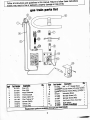
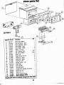
gas train Parts list
F
VP
K.Vt P.tt ttttfi
1
1
2
3
4
5
6
7
7
S11273
511272
514074
511274
511275
511183
S41220
S14073
514072
DercrlPtlon
Pilot(LP)
Pilot(NG)
PiezoElectrode
ThermocouPle
PiezoCable16"
PilotTubing16"
Burner(G4OO)
Orifice(LP)
Orifice(NG)
0tY'
1
1
1
1
1
1
1
1
1
parts "," "*t''"
ReplacemeHt
otv'
ffisdptlon
8
;
;
to
Brass
S11265, 3/8" x 3" NiPPle
1
{tiJ*"eurosit Valve
Block
InteruPtor
{rtr,
1
?2u98t
Z)iaw l'l'o'itvarve'(LP)s
(NG)532t1821
1
MinrateScrew(LP)
1
MinrateScrew(NG)
spillswitchwire Assembly 1
11
11
12
511288
511287
s31258
13
s11276 :l1l^:_T::a,rPiano
S14062
"""t^
EurositCIYIP|"*
""''t*'
ri.r.iiffrdltflFi.:
I
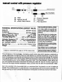
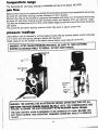
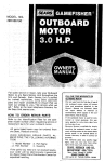
manual control wlth pressure regulator
PILOTBUHNER
6
A = Filter
B = Manualshut-off
Q = FlameFailureDevice
I
,/A
(r.i
D = PressureRegulator
E = Thermostat.
F = PilotAdjustment
HIGH ELEVATIONINSTALLANON
A.G.A.
Oesign
certified
unitsaretested
and
forelaations
Inlets(2)
from0-2000
feet.CM
3/8 NPT Female approved
approved
unilsare
lor
from
Outlets(2)
3/8 NPT Female G4500feet. certified elaations
MaximumWorkingPressure
1/2PSIG Wheninstalling
thisunitatanelentionabove
WorkingTemperature
(oF)
it is necessary
States)
to
32oF to 175oF 2000feet,(inUnited
decrease
the
input
nting
by
changing
the
Thermostat
RangefF)-(Standard) existing
55oFto IOOoF
burnerorificet0 a smaller
size.lnput
Calibration
Temperature
(oF) , 100oFat Hl Knob position should
bereduced
4 percent
foreach1ffi0leel
aborcseala/el.Check
withthelocalgasutility
Max.RegulatedCapacily
N.G.4q,000BTU/hr.(') for
proper
orificesizeidentification.
Min. RegulatedCapacity1o,oooBTU/hr. When
installing
thisunitatanelaation
betneen
PilotFlowRate2.5 Ft./hr.at 0.S" PressureDrop 2000-4500leet
(inCanada)
$einputntingmug
'1.2lb. bereduced
by10percent.
Weight
Wheninstalling
thisunitatanelantionabon
45fi)(inCanada),
check
withlocalauthorities.
yourlocalgascompany
Consuh
lorasigance
in
(') Basedon 1,000BTU/Ff:0.64s.g.gasat 1.00"W.C.
pressuredrop.
determining
theproper
orifice
loryourlocation.
TECHNTCAL
SPEC|FICAT|ONS
(EUROS|TVALVE)
This unit featuresa thermostaticilly,
modulatingeurositcontrolvalvewhichrequiresno electricityto
operate.(Valveshovrnon hge SI;Onceyou haveselectedyourdesiredtemperatureusingthe control
knob,thetemperature
sensingO0tO
willcontroltheamountof fuelconsumedaccordingly.
Forexample
if yousetthe controlknobin the Hi position(110'Rthe temperature
sensingbutbwill reducethe amount
of fuel consumedas yourroomsambienttemperature
rises.lf you haveselecteda lowersettingand
you roomsambienttemperature
risesabovethat settingthe valvewill "shut off" the flowof gas to the
burneruntilthe roomsambienttemperature
drops,at whichtime the valvewill automatically
re-light.
Due to the sensitivity
of the thermostatic
bulb,we recommend
that it be placedin as cool a locationas
possible.
Onepossiblelocationis to placethe bulbon yourgaspipingas farfromthe stoveas possible.The
coolgasenteringyourhomewillkeepthetemperature
sensingbulbcoolallowingmaximumheatoutput.
3
---\
stove Parts llst
(sEEPAGE6)
Koy# Partllumbcr Dorcdptlon
I
2
2
3
3
4
5
6
7
I
I
9
10
11
12
13
14
15
16
17
18
19
S41217
S31189
S31190
541222
541224
S1OO14
S15001
S15011
S37026
S11086
S11066
S110O5
S11O9O
S11007
S41219
S16154
516069
S11211
S32098
532062
S11086
S32397
otv.
1
StoveBackWeld't
1
' Gold
DoorAssemblY
1
'
DoorAssemblYBlack
1
DoorWeld't' Gold
2
DoorWeld't' Black
1
G l a s s ' H iT e m P
3.8'
1/8" WindowTaPe
5.25'
5/8" DoorGasket
1
GlassGliP
3
ScrewCombHO #10
2
HingePin' Brass
2
HingePin' Black
2
P u s hN u t ' 3 / 8 "
1
SPringHandle'112"
1
GasGrate
1
Gas Log Set
1
GlowingEmber
1
AccessDoorHandlec/w Screw
1
BrassTrim 24"
1
BrassTrim 17"
1
ScrewComb#10 HD
1
BurnerDeflectorShield
local dealer'
Replacementparts arc avattablethrough lour
4
11
t \
ANYSAFETYSCREENOR GUARDREMOVED
FORSERVICING
AN APPLIANCE
MUSTBE
REPLACED
PRIORTO OPERATING
THEAPPLIANCE.
''WARNING''
DO NOTOPERATETHE APPLIANCEWITHTHE GLASSFRONTREMOVED,
CRACKEDOR BROKEN.REPLACEMENT
OFTHE GLASSSHOUT
D BE DONEBY A
LICENSED
OR QUALIFIEDSERVICEPERSON.
YOUNGCHILDREN
SHOULDBE CAREFULLY
SUPERVISED
WHENTHEYAHEINTHE
SAMEROOMAS THEAPPLIANCE.
door lock screw
REMOVE
DOORLOCKSCREWBEFOREATTEMPTING
TO OPENDOOR.
BE SURETO REPLACEAFTERSERVTCING
TO AVOIDACCIDENTAL
OPENINGOF DOOR.
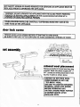
set assembly
-8.>C/:
mlneral wool placement
Remove
a handfulof
mineralwoolfrom
bag
suppfied.
Breakintopiecesroughly314',x
S4".Looselyandevenlyplacewoolin front
log trayof grateas shorn above.
HUTION: DO NOI PACKWOOL
UNDERBURNERDO NOT USE
"TOO ilUCH" WOOL.
USE ONLYIN LOCATIONSPECIFIED.
RE-INSTALLDOORLOCKSCREW
BEFOREOPERATING
UNIT.
UUT,ON; EIVSUREFRONTPORT/ION
OF BURNEN'GA"TESAFIER
, rszlr,r.rwc
wooL.
FIG.A
-a
-------->
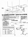
(ipttonal fan klt #S3rr92l
fan lnstallatlon instructlons
1. Removefan fromcarton.
Usingfourscrewsprovidedattachfan.tostoveas shownabove'
2.
'
Be sureto installrubbergrometsas shownabove'
as shown,
3. Speedcontrolswitchis to be insertedintopedestal,
and tightenuntilsecure.
4. Snapvariablespeedcontrolknobinto place'
5. Plugfan in.
FANW|/NINGD/,AGNAM
w illlxo
Elcblcrl Goundl4 Inrtucllonr
wilha
b €quiPPed
Thisappliance
throeprong(grcunding)Plug for
your protsction againsl shock
hazard and should be Plugged
directlyinlo a Pfoporlygrounded
threeprongreceBeclo.
Do not cut or tamwe the groun'
ding pronglromthis Plug'
541225
S41059
S14003
4
S140OS
S140Og
5
W.
G.
B.
FANMOTOR
11OV60Hz 1.5AMP
1lOVLINE
l(cy# Parlllumbor Ducrlpllon
1
2
3
"bbcl tll wlnt
CAUIfOX Drlor to dlrconnrcllon whcn
tcnlcttrg conlrolf. ffirltry ormn
c.n ciure lmProPcr tnd
d.ngarous oPenllon."
"WrW
NoPat oPe/lllton .lLl
canlclng;'
FanCaseWeld't'G40O
MotorAssY- G300
SPeedControlSwitch
PowerCord
SpeedControlKnob
SPEED
VARIABLE
CONTROL
0ty'
1
1
1
1
1
@
6
@-"
CIOTHINGOR OTHERFLAMMABLE
MATER'AISSHOULDNOTBE PLACEDO'V OR
NEARTHE APPLIANCE.
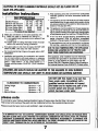
installation instructions
Keepoperatingareaclearand free lrom combustible
materials,gasoline,and otherllammableliquidsand
vapours.
GAS SPECIFICATIONS
shutoffvalvemustbe
Theapplianceandits individual
llaturalGas Propane/LP
Manifold
Pressure
disconnected
fromthe gassupplypipingsystemduring
3.5"W.C. 10.0"
w.c.
Minimum
InletPressure' 5.0"w.c. 11.0"WC.
anypressuretestingof the systemat testpressuresin
Maximum
lnletPressure 10.5"W.C. 13.0"W.C.
excessof 1/2psig (3.5kPa.)
(Max.)
Fl'UInputRating
30,000
26,000
8. Theappliancemuslbe isolatedfromthegassupplypip
(Min.)
BTUInputRating
23,500
23,500
ing by closingits individualmanualshutotf valvedur'For purposeot lnput
Mustment.
ing anypressuretestingof the gassupplypipingsystom
at testpressureequaltoor lessthan112psig(35 kPa.).
2 . Makegas connectionto the valveassemblywith:
for test
9. A 1/8" inchN.Hl-.pluggedtapping,accessible
l) Blackironpipeor malleable
ironfittingsor . . .
gauge connectionmust be provided immediately
ll) A corrugated
metalconnector(notto exceed2 feet
to the appliance.
upstreamof the gassupplyconnection
in length)or . . .
gas
to a chimney
A
not
be
connected
appliance
must
lll) Copperpipeor tubing(internally
tinned)if accepllue
fuel
burning
appliance.
serving
solid
a
soparate
tableto the authorityhavingjurisdiction.
Turngassupplyon andcheckfor leaks.DO NOf USE
DUETO HIGHTEMPERATURES,
THE APPLIANCE
OPENFLAME.Use soapand watersolution.
SHOULDBE LOCATEDOUT OF TRAFFICAND
Forcorrectpositioning
of logson thegrate,referto SET
AWAYFROMFURNITURE
AND DBAPERIES.
ASSEMBLY.
lnstallation
and provisionfor combustionand ventilaThe appliance,when installedmust be electrically
tion air mustconlormwith localcodeso[ in absence
connectedand groundedin accordancewith local
of localcodes,withtheNational
FuelGasCode,ANSI
codesor, in the absenceof localcodes,with the
Z,223|l- latest edition- in the UnitedStatesor, in
currentC9{ C22-1CanadianElectricC'ode(Canada)
or
- Bl49.lnstallation
Canada,
withthecurrentCAN/CGA
TGlatest
theNational
codeANSI/NFPA
edition
Electrical
Code.
CH'LDRENAND ADULTSSHOUTDBE ALERTEDTO THE HATARDSOF HIGHSURFACE
TEMPENNUREANDSHOUTDSTAYAWAYTO AVOIDBUR'VSOR CI.OTHING
'G'V'T'O'V.
DO NOTUSE lfits heater lf any paft has
been under water. lmmedlately call a
qualtfled serylce technlclan to inspect
lhe fieater and to replace any part of the
control system and any gas control
whlch has been under waten
CLEARANCE
TO COMBUSTIBLES
CeilingHeight
Sides
Front
Backof Stove
Minimum= 24"
Minimum= 8"
Minimum= 36"
Minimum= 9"
please note
It is normalforyour CenturyHeatingfireplaceto give otf someodourthe first tlme it is burned.
This is due to the curingof the paintand any undetectedoll from the manufacturingprocess.
Pleaseensurethat your room is wellventllatqd- openatlwindows.
IT IS IMPEBATIVE
THATTHECONTROLCOMPARITUENT
WAYS
BURNER,AND CTRCULATING
AIB PASSAGE
BE KEPTCLEANAND CLEAR.PROVTDE
FORADEOUATE
AND VENTILATION
AIR. PROVIDE
COMBUSTION
ADEOI'ATECLEARANCESAROUNDAIR OPENINGSAND ADEOUATEACCESSIBILITY
CLEARANCEFOR
SERI/ICEANDPROPEROPERATTON.
NEVEROBSTRUCT
ORTHE
THEFRONTOPENINGOFTHEAPPLTANCE
DIRECTVENTTERi'INATIONON THE EXTERIOROF THE BUILDING.
7
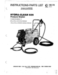
temperature range
and set at the factory'(55-110"F)
(#1 see berowdrawing)is caribrated
The thermostat
gas flow
andturning
bulbbelowroomtemperature
Maximumflowratecanbe checkedby coolingthethermostat
position'
the knob(#4 see belowdrawing)counterclockwiseto the Hl
andturning
bulbbelowroomtemperature
"snap"'
Minimumflowratecanbe checkedby coolingthe thermostatic
the
you
hear
when
rtopping
"no
$;rt
crockwise
counter
drawing)
berow
the knob(#4 see
screw(minimum
pre-drilled
bytheo.E.M.atthe designrt"i" andseiwitfra
Thisflowrateis determined
rate screw).
assureproperflow'
This screw(#3 see belowdrawing)mustbe drivenfully downto
pressure readings
drawingbelow)counterclockwise
tnretpressurecan be checkedby turningcapturedscrew(#6 see
2 or 3 turnsand then placingtubingto gaugeovertest point'
capturedscrew(#7)'
Oulet pressurecan be checledin [he samemanneraboveusing
CAPTURED
BE SURE_I9JIJRN
READINGS,
PRESSURE
AFTERTAKING
WARN'NG;
DO NOTOVERToROUE'
SCREWscLOcKwGi rrnnrLYTO RESEAL.
Screw
PilotAdiushent
MinimunRateScrew
i
Regulalor
Pressure
Pressure
0ullel
Pornt
Test
lnlelPlessure
IeslPoinl
Bulb
Sensing
Iemperalure
DEVICE;AFTERSHUTTINGOFF ALL
THE CONTROLHAS AN INTERLOCK
WARN'NG;
to'
crnHorBERELrirli,r^::t^ Tlt^T*t:3:::i
rHEptLorBURNER
cAsFLow,
iil\cNEiio eene'' r seD(approx.t-
i,il EHH;
8ffiH,i r'rt=*ii"'*'
: .:::'I .
BY HAND'DO ilOT USE
TO BE-OPERATED
THE GAS CONTROLKNOBIS DESIGNED
lN sERlous
RESULT
MAY
DAMAG'6-ftrloes
rHrs opERAiiNG.
ANyrooLs DURTNG
yentlng Instaltailon guldeflnes
PROPER
INSTALLATION
OFGASVENTING
IS AN IMPORTANT
SAFETYAND
APPLIANCE
PERFOFMANCE
CONCERN.
IF YOUARE NOTQUALIFIED,
DO NOT
ATTEMPT
INSTALLATIONS
Oi NCPNIRS
OF
GASAPPLIANCES,
PIPTNG
OR VENTING.
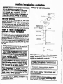
TYPICAL"B'' VENTIT{STALLATION
flsted vents
A listed gas vent is a factorymade and listed system
designed,and instalted
exctusively
toi iemovingp.Oj"tJoi
combustion,excessairi and diiutionair reiutting tro;
burningfuel gas. metalvents,me moslcommontype
of
doubtewailconstruction
enclosingan iniufat_
,"_"1!,9T?l_oy
rngatr space.This air.spac-e
both helpskeep-fluegases
warmandreduceheattransferred
to niarOycbmbusiibles.
lype B vent instalfa$on
lllsted B.Oor G]€aterf
Irfgl" beginninginstailationbe surethattheoverailheight
andGasVentsizeconformto buildingcoJerequiremen-tr.
vents.extendingthroughpitcnJi i*f, ."n exrend
!1q
mrnrmumheightof at lea.stg0Og, (2') higherthan a
any
obstruction
wirhin3m (10').cas venti-dxrenoing
ihiiugf,
roolsarerequiredr6
exireno
"tliili 6db',rn
fla!roofand
iz,)aooie
the
at least60Omm(2')frigfrerinan
anyportion
.ofthe.bu.itdi
ng or adjolnin
g Oujrainglvitfrin'gm
trO,ioi if,"
GasVent.
K e e p E l e c l r i c i tw i r e s
a n d B u i t d r n qI n s u t a l r o n
Awey From Gis Vcnt rnd
O u t O l T h e R e e u r r c dA r t
Sorc:
F rrgglgp
Spacer
EnClosure
Wall
G a sV e n tL e n g t h
25mm fl'l
C l e a r a n c eF o
Combustrbtcs
s u D p o r tP t a t a
li
A d t u s t a b l eL e n g t h
Wherethc Gas vent cxtondsthrough accegslble
8pace3,lt should be cncloseOto iod pereonal
cortactanddamage.Enclosurr,"afli"froufdhare
l1re
Taung9Qualto or grcaterthan thc ftoore
tnrough
whtchthe Gas.%ntpasc-- -xcept In
alnglc
or two-hmily dwelllngr.
Sltuatethe GasVentln the atructureso that lt can
be Inctattedwtrhourcutilnj
i"t.6;;iltr, ptatesor
malortoadbeqtngpartrtroni'oi;;i#;.
teatso
tmportantto locetethe baseof the GasIVent
n9l as posslbteto the heailngappltance. as
is Instaileddtrecili on
I}1,_rl"^,.app[ance
carpeung,.ille
or othercombusilble
materlalbther
thanwoodf toortng,ttraippr[nce;;jil"
Instath
es on a metator woodpanelextendlngthe
full
wldth
and depth of the ippflance.
I
Thlsappllancels equlppedwltha sahty contrcl
syst?mdeslgnedto protectagalnstlmproper
ventlngof combustionproducts.
I
THISAPPLIANCE
MUSTNOTBECONNECTED
TO
A CHIMNEYFI.UESERYINGA SEPARATE
SOLID
FUELBURNINGAPPLIANCE
',:j
Use only vents labelled '.FOR EXTERIORUSE',
above the roofllne.
.Ii i
il
i
1
. r j
lrl
:!l ,
ConsulttheAuthorltyhavlngfurlsdlcilonlo setect
theconectGas\tentiilametJr.
eroic ;t;i a targer
yentdiameter.
than necessary
i'i{
iii
Ilr
ti,
!i
fj
Ji:i
venting installation guldellnes
WARN'NG!
Installationsshouldonly be madeby qualiliedpersonswho are famillarwlth the safety
proceduresrequiredfor the Installationol the Product'who arc equippedwlth the proper
of licensing.
iools and testinginstruments,and who haveathlevedProper.certificatlon
Installationsmadebe unqualiiiedpersonscan resultIn hazardssublectlngthe unqualified
peron to the risk of injuryor electrlcatshockwhlchcan be seriousor evenfatalnot only
io the Installer,but alsoto personsbeingseruedby the equlpment.
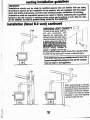
installatlon llisted B.O Yentl continued
CHECKINGVENT CAPACITY
Completeall gas piping,electrical,
and vent connections. After
adiusting the appliance(s)and
../
lightingthe mainburner(s),allowa .r'
coupleol minutssforwarm'up.Hold
a lightedmatchiust underthe rim
r a l t lhood
PerrE l r e r vop€nl l J u ( J lrelief
draft
ofI Ithe
ng g
ofI Ithe
o
ne o
willdrawthe
venting
Proper
ing(s).
u'
hood.
draftrr|",t
ulalt
the
InGt
into
lnto
or
flamelowaro
towardor
ilamg
-:
-
.,'
.(
|
|
..
| - \
Y
ill l -... \*'
V' k)-.
-\
T
-
.\
)
lmproper venting, indicated bY
\
\
escapeor sPillageof burnedgas'
willcausematchto flickeror go out.smokefroma cigarettewill also
be pulledinto the drafthoodif the vent is drawingproperly'
-l
I
I
I
i
Thedratthoodmustbe lfrstalledso asto bein the
sameatmosphiiicpressurezoneas the combus'
tion air Inletto the aPPllance.
Whenventingthrougha side wall
yourventPiPemusthavethe ProPer
rating.Manulacturer's
iemperature
also be maintain'
must
clearances
authoritYhaving
the
ed. Consult
jurisdictionin your area regarding
ventingthroughside wall.
10
il
{xi
venting installation guidelines
WARNING!
Installationsshould only be madeby qualified personswho are familiarwith
the salety
proceduresrequiredfor the installationof the product,who
are equippedwith the proper
tools and testing instruments,and who haveachievedpropercertificaiionof
licensing.
Installationsmadebe unqualifiedpersonscan result in-hazardssublectingthe
unqualified
personto the risk of
or electricalshock which can be seriousor evin latat not only
lnirty
to the instafler,but also to personsbeing servedby the equipment.
chimneys
o Completefamiliarity
with chimneycondition,height,size,
clearanceto combustibles
and otherlactorsis essential.
Consultthe authorltyhavingjurisdictionin your
area regarding masonry chimney venting
applicalions.
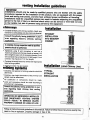
installation
STRAIGHT
INSTALLATION
INTOMASONRY
CHIMNEY
A completechimneyinspectionmadeby qualified
personsshould be performed.
o Appliancesusing B vent connectorsto vent
into a
masonryor factory-built
chimneyshouldnotexceed1-1/2
feetin lengthforeveryinchof connector
diameter
(3 inch
ventconnector
hasa maximum4-ll?tdotlength;5 inch
connector
has maximum7-112
footlength).
. Oversized
chirnneyd
shouldbe relinedwithbppropriate
listedreliningsystems.
r Cleanoutaccessmaybe required.
relining systems
a
a
Suitability
and approval
of reliningmaterials
shouldbe
determined.
Condition,
size,height,termination
of thechimneyto be
relinedmustbe determined.
No substitutionof componentsshould be made.
Jointsand connectors
shouldbe madeaccordingto
manufacturer's
instructions.
installation
gitt"ffiii"y
Liner)
;i
TYPICAL
STRAIGHT
INSTALLATION
OPERATION
OF IMPROPERLY
INSTALLED
AND MAINTAINEDVENTINGSYSTEM
COULD RESULTIN SERIOUSINJURY,
PROPERTY,
DAMAGEOR LOSSOF LIFE.
rr
l,
ri
Consultthe authorityhavinglurlsdictionin your
area regarding listed chimney liner venting
applications.
F-
I
rollowall Instructions
andguidelines
in thismanual.Failureto followtheseinstructions
exactlymay
resultin fire or explosion,
propertydamageor loss of life.
flltrlN
I ErrttrNvs
INSTr|UGTIONS
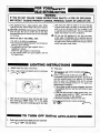
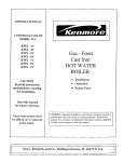
1. Periodicvisualchecksof the pilotshouldbeconducted
lo ensurethat the flameis presentexcgptwhen the
valvecontrolknob is in the "OFF" position.-
GAS CONTROL
removethe logsfromthe grateassembly
2. Periodically
any looseparticlesfrom the grateand
vacuum
and
burnerareas.
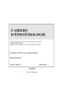
TYPICAL FLAME PATTERN SHOWING
AURNER (A) AND CARRY DOWN POFTS (B)
partsareavailable
directlythroughthe
3. All component
manufacturer.
Writeor phone.
CenturyHeating
Drive,Etobicoke
330 Humberline
Ontario,
Canada,MgW1R5
1-800-836-1210
UnitedStatesWattsLine
1-416-798-2800
Canada
VIEW OF PILOT FLAME
FROM ABOVE
installationand all repairsshould be done by a
qualifiedserviceperson.The applianceshould be
inspectedbeforeuse and at leastannuallyby a
quititiea service person.lt is imperativethat
air
burnersand circulatin-g
control compartments,
passageway's
of the appliancebe kgpJclean.More
ireque-ntclianing may be requireddue.to exces'
sivd lint from carpeting,beddingmaterialetc.
all powerto unitbeforeservicing'
5. Disconnect
WARiltNG: DO NOr ADJUSTTHE GASORIFICE.KEEP.AREACLEARAND FREEFROM
ANDLIQUIDS.
VAPOURS
AND OTHERFLAMMABLE
GASOLINE
MATERIALS,
COMBUSTIBLE
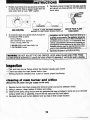
inspection
- Pilotand main burnerflamesshouldbe checkedvisuallyeach month.
- Checkand cleanthe mainburneronce a year.
- Ventingshouldbe checkedoncea yearto assureproperfunctioning.
cleaning of main burner and orifice
(Dlsconnect all power and gas supply to fhe unit).
1. Removeburnerholddownscrewsand removeburnerand burnerdeflectorshield.
2. Usinga vacuum,cleanbottomof fireboxand orifice.
3. Cleai burnerpartsusingvacuumand any particalsthat may be lodgedin portsare to be removed
using a small wire or paperclip.Ensurethat all partsare free from debris.
burnerand burnerdeflectorand put logs in their properlocation.
4. Re-install
12
F('r| V('U]| SAFETY
BEADBEFORE
LIGHTING
WARNING:
IF YOU DO NOT FOLLOWTHESEINSTRUCTIONS
EXACTLYA FIREOR EXPLOSION
MAYRESULTCAUSINGPROPERIYDAMAGE,PERSONALINJURYOR LOSSOF LIFE.
This appliancehas a piezoignitionpilot.When
lightingthe pilot,followtheseinstructions
exacily.
b. BEFORE
LIGHTING
smellatlaround
theapptiance
area for gas. Be sure to smell next to the floor
becausesomegasis heavierthanairandwillsetile
on the floor.
WHATTO OO IF YOUSMELLGAS
o Do not try to lightanyappliance.
r Do nottouchanyelectrical
switch;do notuseany
phonein yourbuilding.
r lmmediately
call yourgas supplierfroma
phone.
neighbour's
Followthe gas supplier'sinstructions.
o lf you cannotreachyourgas supplier,
call the
fire department.
-
LIGHTING
TNSTRUCIIONS
1. STOP!Readtfresafetyinformation.
2. Pushin gascontrol
knobslightly
andturnclockwise
lo "OFF".
Waitfive(5) minutesto clearout any gas.lf you
then smellgas,STOP!Follow"8" in the saiety
information.
lf youdon'tsmellgas,go to nextstep.
-TO
TUI|N
Use only your handto push in or turn the gas
controlknob.Neverusetools.lf the knobwill not
pushin or turnby hand,don'ttry to repairit, call
a qualifiedservicetechnician.
Forceor attempted
repairmay resultin a fireor explosion.
d . Do not use this appliance
if any part has been
underwater.lmmediately
call a qualifiedservice
technician
to inspecttheappliance
andto replace
anypartof the controlsystemand anygascontrol
whichhas beenunderwater.
-
4. Find pilot.
5. Turn knob on gas controlcounter-clockwise
to "PILOT".
r6. Pushin controlknoballthewayandholdin.
lmmediately
lightthe pilotwithignitor,Continueto
hold the controlknob in for approx.(2) minutes
afterthe pilotis lit. Releaseknoband it will pop
backup. Pilotshouldremainlit. lf it goes out,
repeatsteps5 throughL
r lf knobdoesnotpopup whenreleased,stopand
immediately
callyourservicetechnician
or gas
supplier.
. lf the pilotwillnotstaylit afterseveraltries,turn
the gas controlknob to "OFF" and call your
servicetechnician
or gas supplier.
r Disconect
all powersourceto the unit,
Turngas controlknobcounter-clockwise
to "ON".
r-.
('FF GAS T ( , A P P L I A N G E -
1. Pushin gascontrolknobslightlyandturnclockwise
to "OFF". Do not force.
/-:r
-
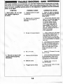
T}Io)UBLE
G4OO
SHOOTTNG.
yournewGasFireplaceshouldprovideyeaq of troubl+
Withproperinstailation
and maintenance,
guideshownbelow.This
treedervice.lf you do experiencea problem,referto the troubleshootingguidewill assiit a qualiiied servic'epersionin the diagnosisof problemsand the correctlve
action to be taken.
SYMPTOM
l. Spark tgnitor will not light
after repeatedtriggerlng of
red button.
POSSIBLE CAUSE
lgnitor(no spark
A. Defective
at electrode).
CORRECTIVE ACTION
1. Check for spark at electrode
and pilot;if no sparkandelectrode
wire is properlyconnecled,
replaceignitor.
B. Delectivepilotor misaligned
electrodeat pitot(sparkat
electrode).
1. Usinga match,lightpilot'lf pilot
lights,turn otf pilot-andtriggerthe
red buttonagain.lf pilotlights,
an imProPergas/airmixture
lighting
causedthe imProPer
longer
a
and
PurgePeriodis
lf Pilotwill not
recommended.
light'check gap at electrode
and Pilot' shouldbe 1/8inchto
havea strongsPark'
lf OK, rePlacePilot'
c. No gas or low gas pressure.
'
1. check remoteshut off valves
lrom fireplace.Usuallythere is a
valvenearthe firePlaceand
thereis a valvenear
sometimes
the main.Therecan be morethan
one (1)valvebetweenthe fireplace
and main'
'
canbe causedbY
2. Lowpressure
suchas a
a varietyof situatlons
bent line,too narrowdiameterof
pipeor evenlow line Pressure.
Checklor kinkedlines.lf none,
consultwith Plumberor gas
supplier.
ll. Pilot will not stay lit after
caretullyfollowinglighting
Instructions.
D. No L.P.in tank.
YoumaY
1. CheckL.P.(ProPane)
be out of fuel.
A. Defectivethermocouple.
1. Checkpilotflame'MustimPinge
Cleanand or
on thermocouPle.
llame
pilot
maximum
for
adjust
on thermocouPle'
impingement
B
Defectivevalve.
C. Pluggedburner orifice.
14
1. Replacevalve- (lt is not
fieldserviceable).
1. Checkburnerorilicetor stoP'
page and remove.
-
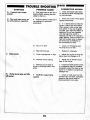
TFOUBLE
sYlrPTOm
lll. Frequentpilot outage
problem.
lV. Pilot and maln burnergo
out white belng in operation.
SHOOTING
- G4('('-
POSSTBLE GAUSE
A. Pilotflame may be too low or
blowing(high),causingthe pitot
safetyto drop out.
CORBECT.IVE AGTTON
1. Cleanand adjustpilotflame
for maximumflameimpingement
on thermocouple.
A. Highlimitswitchis defective
or
has reachedit's maximum
temperature.
1. Allowunitto cool.Thenrepeat
lightinginstructions.
2. lf 1. abovedoesnot allowfor
ignition,checkhighlimitswitch.
Placejumperwiresacrosshigh
limitswitch.ll youcan re-ignite
the pilot,yourhighlimitswitchis
defective.Do not use fireplace
untilthe high limitswitchis
replaced,as this is an important
safetyfeature.lf the unit does not
lightwithjumperwiresin place,
the wiresmay be defectiveor
the connectorsare bad.
V. Glasssoots.
....
Vl. Flameburns blue and lifts
otl burner.
B. NO L.P.in tank.
1. CheckL.P (Propane)
tank.
Youmay be out of fuel.
C. Bad thermocouple.
1. Replaceif necessary.
A. Flameimpingement
on logs.
1. Adjustthe log set so that the
flamedoesnot impingeon if.
B. lmproperventurisetting,
1. Adjustthe air shutteral the
baseof the burner.
C. Minwoolaroundbaseof
burneror blockingbottomlront
grille.
1. lnspectthe baseol the burner.
It is imperativethat NO material
be placedaroundthe baseof the
burneror in bottomfrontgrilleair
passageway,
A. Insufficient
oxygenbeing
supplied.
1. Checkto makesurethat the
minwoolhas not been improperly
placedat the burnerbaseor
blockingbotlomfrontgrille.
15
\'ENTTNG Pl|OBLEMS
TROUBLE SHOOTING
Mostventingproblemsarecausedby incorrect
ventsizing,improperinstallation,
or inadequate
air supply.A preliminarycheck for a field
problemmightinclude:
Venting Condltion
Loosejointscan affectdraftandcausespillage.
Mashed-invent sectionsand damagedvent
caps can restrictflow and cause spillage.
Examineand replaceas needed.
. Usinga draftmeterto determineif venting
systemdraftmeetsmanufacturer's
specifications.
Obsfructions
Smallanimalsor birdsmaygetintoand block
the vent or drafthoodoutlet.Dust,lint, and
foreignobjectsmayobstructair inlets.Remove
and cleanoPenings.
obstructions
r Checkingthe vent sizing accordingto
manufacturer'sspecifications,
appliance
input,and ventingconfiguration.
LateralRun (L)
runscause
or non-vertical
Lengthyhorizontal
resistance
to flowandmayreducedraftenough
Thepitchof lateralrunscan
to causespillage.
also be a problem;lateralruns shouldbe
run from
pitched114"riseperfootof horizontal
vent.
the
the applianceto
r Examiningthe entireventingsystemfor
faults such as disconnectedjoints or
damagedventsections.
o Makingsureventand air openings
arenot
obstructed.
Elbows
Too manyelbowscauseexcessiverestriction
Usually,
two
of flowand mayresultin spillage.
in a properly
90 degreeturnscanbe tolerated
sizedventingsystem.Morethan two maychangingthe
and necessitate
causeproblems
system.
lf theseprocedures
do not revealthe source
problem,
of the
may include
troubleshooting
attentionto common venting problems
discussedbelow.
FLUEGAS SPILLAGE
Negativepressure in the Dwelling
An extremellytight house may not supply
andventingair.Useof
adequatecombustion
mechanical
exhaustsuch as a dryerventor
rangevent may worsenthe problem.An air
systemmustbe installedInthedwell'
exchange
ing to correctthis Problem.
Spillageoccurswhenflue gasescannotexit
theventsystemandbackup intothedwelling.
A primarysymptomof appliancesequipped
with a VentSafetyShutoffSystem(flue spill
switch) is unexplainedapplianceshutoffs.
Othersymptoms
of fluegasspillageat thedraft
hood include cendensationon walls and
windowsand/ornoticeable
odours.Butspillage
may also result in the releaseof carbon
highlytoxic
a colourless,
monoxide,
odourless,
gas.A simplespillagetestcan be conducted
if spillageis suspected;
see ownersmanual.
CAUSESOF SPILLAGEAND
ACTION
CORRECTIVE
IncorrectVentSizing(H)
lf theventis toosmallor tooshort,spillagemay
dilution
occur.lf theventis toolarge,excessive
air may cool flue gases and reducedraft,
Theventcapsizeshouldalso
causingspillage.
instrucbe checked.Check manufacturer's
tions,applianceinputrating,and appropriate
sizingtables.
16
Flue Gas Cooling
Venting exposed to extremelY cold
or ventingof singlewallconstructemperatures
tion lose heat needed to maintaindraft;
massivemasonrychimneysabsorbneeded
draft
heat. lf the flue gasescool excessively,
is reducedandspillagemayresult.Useproper
insulateand protectproperly'reline
materials,
when necessary.
Down Drafts
tn certain wind conditionsand in certain
relationshipswith nearby structuresand
objects,high pressureconditionsrnayatfect
draft negatively.Relocatethe vent cap, raise
its heighl,or use an approvedhighwindcap.
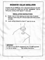
DECORATIUE
COLI.AR
INSTALLATION
Supplied
withyourG400gasunitis a decorative
collaryoumaywish
"woodstove"
to useto enableyouto giveyourunitthat
lookby
hidingyourventinginsideregular6" stovepipe.
INSTALLATION
INSTRUCTIONS
1.
Centercollaron ventopeningand markholes(3 places).
Drillthe3 marksusing118"drillandinstallcollarwith3 screws
provided.
2.
Installventingfollowed
by black6" pipeas yougo.
IMPORTANT
6" pipeis fo be usedfor appearance
only./f ls NOf approved
for useas venting.
See ventinginstrucfrons.
17
2695 Meadowvale Boulevard
Mississauga, Ontario L5N 8A3 Canada
(800) 668-5323
CFM Corporation
www.cfmcorp.com