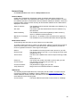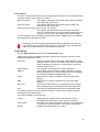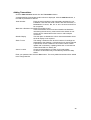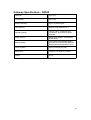
1
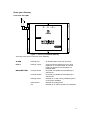
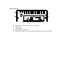
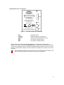
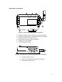
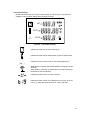
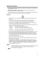
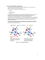
RF500 GATEWAY SYSTEM MANUAL Comark Wireless Monitoring - RF500 System Manual Contents RF500 System Components.....................................................................................................4 RF500 Gateway....................................................................................................................4 Transmitters..........................................................................................................................5 RF512 Temperature Transmitter.......................................................................................5 RF512M Temperature Transmitter Backbone Option........................................................5 RF513 Temperature and Humidity Transmitter..................................................................5 RF513M Temperature and Humidity Transmitter Backbone Option..................................5 RF515 Analog Input Transmitter and RF515A Connection Box.........................................5 RF516 Precision Temperature Transmitter........................................................................5 Optional Accessories.............................................................................................................5 Know your Gateway..............................................................................................................6 Front View with LEDs.........................................................................................................6 Rear Connections..............................................................................................................7 Side Switches and Connections.......................................................................................8 Know your Transmitter..........................................................................................................9 Transmitter Display..........................................................................................................10 Safety Information...................................................................................................................11 Warning...............................................................................................................................11 WEEE..................................................................................................................................11 RF500 Wireless Monitoring System Overview........................................................................12 Gateway – Introduction........................................................................................................12 Overview of RF500 Mesh Networking.................................................................................13 Meshing Transmitters and Backbone Transmitters.............................................................14 Automatic Data Retrieval (ADR)..........................................................................................14 Equipment Installation.............................................................................................................15 Gateway Fixing....................................................................................................................15 Transmitter Fixing................................................................................................................15 Mains Wiring........................................................................................................................15 Ventilation............................................................................................................................15 Powering On and Off...............................................................................................................16 Switch On............................................................................................................................16 Gateway Switch OFF...........................................................................................................16 Transmitter Activation..........................................................................................................16 Gateway Commissioning........................................................................................................17 Requirements for Commissioning.......................................................................................17 Gateway to PC Network Connection via RJ45 cross-over Ethernet Cable..........................17 Gateway to PC Network Connection via Modem.................................................................20 Viewing the Commission-Gateway Web Pages..................................................................24 Setup of First Administrator.................................................................................................25 Gateway Language.............................................................................................................25 Gateway Name....................................................................................................................25 Gateway Clock Setup..........................................................................................................25 Network Setup.....................................................................................................................26 Network Details................................................................................................................26 Modem Email Details.......................................................................................................26 SMS Details.....................................................................................................................26 Email Options..................................................................................................................27 Email Setup.........................................................................................................................27 Adding Transmitters............................................................................................................28 Gateway Programming and Use.............................................................................................29 Gateway Specification – RF500..............................................................................................30 Transmitters Specification.......................................................................................................31 Changing Lithium Battery on RF500 Series Transmitters.......................................................33 Battery Reordering..............................................................................................................33 2 Battery Change Procedure..................................................................................................33 Check for Transmitter Errors...............................................................................................33 Pinout and Wiring....................................................................................................................34 Door Connector...................................................................................................................34 Lumberg Connector.............................................................................................................34 Power Connector.................................................................................................................34 Gateway Relay Outputs.......................................................................................................34 FCC Approvals........................................................................................................................35 Equipment Ratings..................................................................................................................35 Supply Voltage....................................................................................................................35 Environmental Conditions....................................................................................................35 Gateway Storage/Operating Conditions...........................................................................35 RF51X Transmitter Operating Conditions........................................................................35 RF51X Transmitter Storage Conditions...........................................................................35 RF515 Maximum Input Conditions......................................................................................35 Maintenance and Cleaning.....................................................................................................36 EC-Declaration of Conformity.................................................................................................37 Transmitter Error Codes..........................................................................................................38 Gateway Fault Conditions.......................................................................................................38 Definitions of Gateway Terminology.......................................................................................39 Glossary..................................................................................................................................40 Document Revision History.....................................................................................................41 3 RF500 System Components RF500 Gateway The RF500 Gateway Kit consists of the following items. RF500 Gateway Part No. RF500 Transmitter Activator (2-off) Part No. RF525 Jack Plug 2.5mm (2-off) Part No. RFJACK High Gain Antenna. Part No. RF504 DC Adaptor. Mains Lead with either UK, EU or US plug. 4 Transmitters RF512 Temperature Transmitter Integral temperature sensor plus connectors for two external temperature sensors and an external door sensor. External temperature range: –40°C to +125°C RF512M Temperature Transmitter Backbone Option Integral temperature sensor plus connectors for two external temperature sensors and an external door sensor. External temperature range: –40°C to +125°C Includes High Gain Antenna and RF520 DC mains adaptor. RF513 Temperature and Humidity Transmitter Integral temperature sensor, one integral humidity sensor and connector for an external door sensor. Integral temperature range: –30°C to +70°C Humidity range: 10-90% RH RF513M Temperature and Humidity Transmitter Backbone Option Integral temperature sensor, one integral humidity sensor and connector for an external door sensor. Integral temperature range: –30°C to +70°C Humidity range: 10-90% RH Includes High Gain Antenna and RF520 DC mains adaptor. RF515 Analog Input Transmitter and RF515A Connection Box Two analog input channels, each capable of configuration as 0-1V, 0-10V or 4-20mA using RF515A connection box. RF516 Precision Temperature Transmitter Integral temperature sensor, and connector for one external temperature Pt100 sensor and an external door sensor. External temperature range: –200°C to +400°C Each transmitter is packed with a mounting bracket and 2-tie-wraps. Optional Accessories RF520 RF502 RF503 RF500BACKUP DC mains adaptor for RF512 and RF513 Bridge. 0.5m lead to enable transmission through RF resistant barriers Bridge. 1.0m lead to enable transmission through RF resistant barriers RF500 Backup Server Software 5 Know your Gateway Front View with LEDs ALARM FAULT MAINS/BATTERY RF500 Gateway Figure 1 - Front view of RF500 Gateway There are three LEDs on the front of the Gateway: ALARM FAULT Flashing Red Flashing Yellow MAINS/BATTERY Constant Green Constant Amber Flashing Green Amber/Green Off An enabled alarm event has occurred Contact technical support from your local distributor or Comark Limited. The Home Page may provide more information on possible faults DC power is available and the Gateway is switched on DC power is available and the Gateway is switched off Gateway is on and running off battery packs, no DC power available Gateway is shutting down Gateway is off and DC power is not available 6 Rear Connections A B D C C E Figure 2 - Rear view of RF500 Gateway A. B. C. D. E. Modem Jack – Connect to RJ11 line cord (If fitted) 12 VDC input Cable clamps RJ45 Ethernet LAN Socket Rear panel connectors. Do not connect any equipment to any other connector 7 Side Switches and Connections AUX RF500 GATEWAY SERIAL No 1 2 STATUS Comark Limited Hitchin, Herts SG5 1RT Tel: +44 (0)844 815 6599 Comark Instruments Inc PO Box 9090, Everett, WA 98206 Tel: 503 643 5204 www.comarkltd.com 3 4 ON/OFF SW1 MADE IN UK FOR INDOOR USE ONLY DO NOT MOVE WHEN IN OPERATION SW2 Figure 3 – Left Hand Side View of Gateway AUX STATUS ON/OFF SW1 SW2 Reserved Switch Reserved LEDs for Comark use Gateway Startup/Powerdown switch Jack Socket - Relay Output-1 Jack Socket - Relay Output-2 SW1 & SW2 are two switched outputs provided for connection to customer alarm indicators, via relay contacts with 12V 500mA rating, configurable for either NO (Normally Open) or NC (Normally Closed). These are marked as SW1 and SW2, and are in the form of 2.5mm Jack Sockets. Plugs to fit these sockets are available from Comark, part number RFJACK. With the Gateway switched OFF the relays are in a Normally Closed condition, this may cause any equipment connected to the contacts to energise. 8 Know your Transmitter A B C D E F Figure 4 - Front view of RF512 Series Transmitter A. B. C. D. E. F. Alarm LED. Flashes red to indicate any one channel in alarm Active LED. Flashes green to indicate external power detected Infra-Red interface. For Comark use only Antenna. (Do not remove whilst in operation) Lashing eye - Four available Internal temperature sensor A B C Figure 5 - Connector view of RF512, RF515 & RF516 Transmitter A. Lumberg Socket for Probe B. Socket for Door & RF525 Activator (Dual function) C. External DC adaptor socket 9 Transmitter Display RF500 transmitters all have a liquid crystal display as shown below. Only RF512 is capable of using all three display areas and annunciators. INT EXT1 EXT2 Figure 6 - Transmitter Display Indicates that the door channel reads open Indicates that the internal lithium battery requires replacement Indicates that any channel has an unacknowledged alarm When steady, indicates that the transmitter has logged onto the Gateway When flashing, indicates the transmitter is currently attempting transmission with the Gateway. Indicates that the sensor or probe is broken. Indicates that the number to be displayed is too big to fit on the LCD. E.g. 2000 cannot be shown on a "1999" digit area. 10 Safety Information Under no circumstances may a user make any changes to the RF500 Gateway that would alter its performance. Any modification would void the CE compliance of the Gateway and may invalidate any warranty. If the equipment is used in a manner not specified by Comark, then the protection provided by the equipment may be impaired. No user serviceable parts are provided in RF500 Comark Wireless Monitoring Equipment. Contact Comark or your local distributor for all service requirements. Warning • Before connecting or disconnecting the antenna, ensure anti-static precautions are observed. • Use only the Linearity Electronics 12V mains adaptor; Model LAD6019AB5, or Stontronics 12V mains adaptor; Model T3068LN with the RF500 Gateway. • Do not modify the Linearity Electronics 12V mains adaptor; Model LAD6019AB5, or Stontronics 12V mains adaptor; Model T3068LN in any way. • Use only the PHIHONG, PSM11R-050 5V mains adaptor with RF512 and RF513. It is supplied by Comark Limited as three variants: RF520 Transmitter mains adaptor with UK plug RF520/EU Transmitter mains adaptor with European style plug RF520/US Transmitter mains adaptor with North American style plug • Do not modify the PHIHONG, PSM11R-050 5V mains adaptor in any way. • RF512, RF513, RF515 and RF516 Transmitters contain a C-size lithium cell. This cell must not be incinerated or subjected to temperatures in excess of 100°C. Do not deform, mutilate, crush, pierce, disassemble, recharge or short circuit. Such abuse can result in loss of seal, and/or cell explosion. Also exposure to humid conditions for long periods should be avoided. • Do not insert metal objects into connectors. • Ensure the antenna is securely connected before powering the equipment. Internal damage may result otherwise. • The Gateway and Transmitters have been designed to operate with the antenna supplied by Comark, and having a maximum gain of 7dBi. Antennas not supplied by Comark or having a gain of greater than 7dBi are strictly prohibited for use with this device. The required antenna impedance is 50 Ohms. If in doubt please contact Comark or Distributor for advice. WEEE The RF500 Gateway, RF512, RF513, RF515 and RF516 Transmitters contain a non-rechargeable lithium battery. This battery must be disposed of in accordance with local regulations. 11 RF500 Wireless Monitoring System Overview Gateway – Introduction The RF500 Gateway is an embedded microprocessor device containing a radio module for RF communications to the measuring transmitters. The radio module uses a licence free band in the 2.4GHz spectrum. Comark Limited use proprietary protocols over a standard IEEE 802.15.4 link. These protocols achieve reliable communication between the transmitters and the Gateway via self-healing mesh radio networks. Data from measurements taken by the transmitters is stored on the RF500 Gateway in contrast to other systems which store their data on a PC using special software. For operating the RF500 system the only software required is a Web Browser such as Internet Explorer or Firefox. There is no requirement to install software on each users PC. The Gateway contains sufficient data storage capacity for up to 10 years which can be automatically backed up to a PC using the optional RF500 Backup Server software or by manual request to generate and download a backup file via your web browser. Connection to the Gateway is via Network (Ethernet) connection or remotely via optional analogue modem. For modem access a dedicated Analogue phone line must be provided. An external power adaptor provides the mains power for the Gateway. An internal NickelMetal-Hydride (Ni-Mh) rechargeable battery is included, this provides normal operation of the Gateway during power failure until the battery is exhausted, The Gateway then shuts down until power is restored. Two relay connectors are provided for external alarms, Autodiallers/Klaxons etc. All other connections to the Gateway are disabled. See Figure 3 – Left Hand Side View of Gateway for further details. Emails for alarms will be instigated directly from the Gateway. It is also possible to send a text message alarm via email using a third party provider. The Gateway can be either desk mounted or wall mounted. Wall mount keyhole slots are provided on the case. The external long range Antenna has variable orientation to suit vertical or horizontal mounting. Three LEDs on the Gateway display current status of the system – Mains/Battery, Alarm indication, and Fault indicators. 12 Overview of RF500 Mesh Networking The RF500 Wireless Monitoring System uses the IEEE 802.15.4 radio transmission standard to implement a radio mesh network. A mesh network is comprised of the following devices: • Gateway • Mesh Transmitter • Transmitter On installation each transmitter is associated with a particular Gateway by serial number. Messages are transferred between transmitters and the Gateway using two-way communication with acknowledgement of successful message reception. Transmitters which are physically close to their associated Gateway such as transmitter A in Figure 7 below, will most likely transmit directly to it. Others such as transmitter B which are further away rely on meshing transmitters to forward messages to and from the Gateway on their behalf. The route taken by the message can vary depending on network load and link reliability. The ability to dynamically reconfigure the network is termed self-healing. In the figure below the self-healing ability is shown. Gateway Mesh Transmitter Transmitter A A B B ! Data transfer interrupted transmitter continues to store data. Transmitter reroutes to self-heal network and transfers stored data. Figure 7 - A Typical Mesh Network 13 Meshing Transmitters and Backbone Transmitters Whenever a RF512 or RF513 transmitter is powered by a RF520 mains adaptor it will become a Meshing unit and will form part of the radio mesh network. However if external power is removed it will revert back to a normal transmitter. RF512 and RF513 have the option to become “Network Backbone” units or routers which will intelligently forward messages on behalf of other transmitters. This option is enabled using a setup option in the Gateway. See Adding Transmitters on page 28. Backbone transmitters will form part of the mesh network continuously even when not powered by a RF520. Due to the very large drain on the internal battery, backbone transmitters must be powered using a RF520 mains adaptor. The internal battery is considered only as a backup battery for backbone transmitters. Automatic Data Retrieval (ADR) The fact that transmissions between transmitters and the RF500 Gateway are acknowledged ensures that the transmitters know exactly which data records have been successfully transferred to the Gateway and those which must be re-transmitted. Therefore if the Gateway is temporarily unable to receive or transmit messages for whatever reason, data will not be lost during this period. When the Gateway is again able to receive and transmit properly the transmitters will re-transmit those records which were unable to be transmitted during the period of outage. This re-transmission of data happens automatically without user intervention and results in seamless graphical and tabular data with no gaps. 14 Equipment Installation Comark Limited strongly recommend that RF500 System installation is carried out by a Comark Installation Engineer or by a Comark Authorised Distributor or Agent. Gateway Fixing Mounting of the Gateway is possible using the keyhole screw fixings provided on the rear of the Gateway itself. However the fixings used are to be determined by the installation engineer depending on the type of material used in the construction of the area where the Gateway is to be placed. To avoid accidental disconnection, the DC power cable and cables connecting to the Relay Outputs should be secured using the cable clamps provided on the Gateway case. See Figure 2 - Rear view of RF500 Gateway. Positioning of the Gateway should be in such a way as to limit the risk of liquid being spilt on it as damage may result. The area adjacent to the fan outlet is the mounting surface for the internal hard disk, do not cover this area or mount the mains adaptor here otherwise there is a risk that the hard disk may overheat. Transmitter Fixing Mounting of the transmitters is possible using the mounting bracket provided. The bracket is fixed using 2 screws and the transmitter then slides into the bracket from the top. With each transmitter Comark Limited provide two cable ties which, once the transmitter is slid into the bracket, can be fed through the slots in both bracket and transmitter case to retain it. The door and DC power cables should be tie-wrapped to the bracket to avoid accidental disconnection. Mains Wiring Connections to mains supply for the Gateway and powered Transmitters is via the mains adaptors supplied and a locally installed socket. Any power requirements for the hardware will be determined during survey and should be installed by qualified electrician and certified as safe to use before installation can be started. Ventilation At no time should the exhaust from the Gateway fan or the air intake grill be covered or obstructed. At least 100mm of free space must be provided above and below the Gateway to ensure that sufficient airflow is maintained through the case to provide adequate cooling. Failure to do this may result in damage to the Gateway due to overheating and invalidation of any warranty. 15 Powering On and Off This chapter covers connectors, switching on and off. Switch On PLEASE ENSURE THE ANTENNA HAS BEEN FITTED. IT IS ESSENTIAL TO AVOID DAMAGE. 1. Plug the Gateway mains adaptor into the socket on the underside of the Gateway. The Mains/Battery indicator should show steady amber. 2. Using a paper clip or similar object, press in and hold the ON/OFF switch on the side of the Gateway for 4 seconds. Refer to “Figure 3 – Left Hand Side View of Gateway”. The Gateway will beep once and the Mains/Battery indicator shows steady green. Gateway initialisation will begin. The Gateway contains an internal backup battery, if this battery is not sufficiently charged, the Gateway will not switch on. Once external DC power is connected the internal battery will begin recharging. Whenever the charge state becomes sufficient the Gateway will automatically start as requested. Whilst in this mode Status LEDs 2, 3 and 4 will flash together. See Figure 3 – Left Hand Side View of Gateway for location of these LEDs. i i It takes a few minutes for the Gateway to initialise. A sequence of 2 beeps followed by 4 beeps indicates successful initialisation. Gateway Switch OFF To turn the Gateway OFF press and hold the ON/OFF switch for 4 seconds. The Gateway will beep once and the Mains/Battery indicator will flash green and orange to indicate shutdown. This will initiate an orderly shutdown of the Gateway during which the Gateway will beep 50 times and could take up to 5 minutes. After shutdown is complete the Mains/Battery indicator shows steady orange. Transmitter Activation RF500 transmitters are despatched in a disabled state to preserve the battery. To activate these, insert the RF525 Activator into the 3-pin socket marked B in “Figure 5 - Connector view of RF512, RF515 & RF516 Transmitter” until the display is enabled then remove the RF525. Once activated, transmitters can only be de-activated by removing the battery. 16 Gateway Commissioning This section covers network connection, network configuration, setting date and time, adding users and adding transmitters. The Gateway is commissioned using a Web Browser via a Network connection. This connection can be via cross-over RJ45 cable (recommended) or via modem (if fitted). Requirements for Commissioning • PC with RJ45 Ethernet jack or Modem • Ethernet cross-over cable • Static IP address and subnet mask (Usually allocated by IT Department) • Default Gateway IP address (To enable access from different subnets) • Email server name or IP address • DNS server IP address (required if Email server is named) • For modem connections telephone sockets for the Gateway and PC modem plus associated leads are required. An IP address is not required for modem only operation. Gateway to PC Network Connection via RJ45 cross-over Ethernet Cable You should undo these steps once you have completed commissioning the Gateway. ● Connect the cross-over Ethernet cable between PC and RJ45 jack on the Gateway. ● Set up your PC temporarily with a fixed IP address using the following instructions for Windows 98, ME, 2000 and XP. 17 1. Go to the Windows control panel and double-click the Network icon or the Network Connections icon 2. Right-click on the “Local Area Connection” and select Properties Figure 8 – Local Area Connection Properties 3. In the General Tab select the “Internet Protocol TCP/IP” item and click on the Properties button 18 Figure 9 – General Tab 4. Select the “Use the following IP address” button 5. Enter the following IP address: 192.168.25.200 6. Enter the following subnet mask: 255.255.255.0 then click OK 19 Gateway to PC Network Connection via Modem This procedure requires that the PC and Gateway have a modem installed. For Windows 98, ME, 2000 and XP Figure 10 - Internet Options 1. 2. 3. 4. 5. 6. 7. 8. 9. Start Internet Explorer From the menu bar click Tools then Internet Options… In the Connections Tab click the Add button Using the “Network Connection Wizard”, follow the steps, entering the information below Select the “Dial-up to private network” option In “Phone Number to Dial” enter the phone number of the socket into which you plugged the Gateway. If you are using an exchange line to dial out, a prefix may be required In “Connection Availability” – Create this connection “For all users” In “Finished” – Type a “Connection Name” for example “MyRF500” and click the Finish button Click the Finish button to close the Wizard 20 Figure 11 - Enter the Password 10. Enter both the User name and Password as “RF500 - - - - - - -”. Do not literally type the dashes but replace them with the serial number of the Gateway 11. Click the Properties button 21 Figure 12 - Connection Properties 12. In the “Networking” tab, deselect the “Client for Microsoft Networks” item then click OK. You will be returned to the “MyRF500 Settings” screen showing the password. Click “OK” 22 Figure 13 - Internet Options 13. Select the “Always dial my default connection” item and click “OK” 14. Connect the Gateway modem jack to an analogue telephone outlet using the appropriate lead and adaptors. Ensure the PC modem is also connected to a telephone outlet Internet Explorer will now be configured for dial up to the Gateway. 23 Viewing the Commission-Gateway Web Pages Each Gateway is shipped with a default IP address of 192.168.25.220. Start the Web Browser on the PC and enter this address into the Address Bar. Press “Enter” key or click “Go”. Figure 14 - Browser Address Bar The Gateway login screen will be displayed. Figure 15 - Gateway Login Screen 24 Setup of First Administrator As shipped, the Gateway has no users configured except for a special “one-time-use” installation user which enables an installer to add the main Administrator to the Gateway. Thereafter this Administrator’s username is used to perform all subsequent commissioning. 1. 2. 3. 4. 5. 6. 7. 8. 9. 10. At the Gateway user login screen, type the Username “comark” and click Enter At the password screen enter “42” and click Enter You will be logged into the Gateway as the installation user The Gateway will inform you that “You are about to commission a new system” Click on the Enter Administrator Details button When the Add 1st Administrator screen appears fill in the fields with the Username and Password of your choice In the top left box, marked “Password Required”, enter the installation password:”42” and then click the Submit button If successful the Gateway will return the message “New user added” Click the OK button to return to the Gateway user login screen Login as the new Administrator you just created Gateway Language The language the Gateway uses in web pages and in emails can be changed as follows: Click the Administration button then the Language button. Click the radio button below the flag corresponding with your choice of language. Enter your password and click the Submit button. The language selected is used immediately for all web pages and emails generated for all users. There is no need to reset the Gateway or Login again. Gateway Name A Gateway name is required for email operation. Click the Administration button then the Gateway Name button. The Gateway Name is any name you choose for the Gateway and will be used in the “From:” field in email and SMS notifications. This is important if you have more than one Gateway in your wireless system and all should be unique. Gateway Clock Setup Click Administration button then the Set Clock button. Enter the current date and time using a 4-digit year. Enter your password and click the Submit button. The Gateway will automatically reset after this step. 25 Network Setup Click Administration button then the Setup Network button. Network Details Usually the IT Department will allocate a static IP address and subnet mask for the Gateway. Enter these using dotted decimal notation into their respective fields. If access from different subnets is required also enter the Network Gateway IP address. Users who implement MAC address access security will find the MAC address of the LAN interface displayed in this screen. Static IP Address Net mask Default Gateway Mail Server IP Address DNS no The IP address which has been allocated to the Gateway. E.g. 192.168.25.220 The subnet mask associated with the above IP address. E.g. 255.255.255.0 The IP address of the network gateway to allow access by users on a different subnet (optional) The name or IP address of your local mail server (optional) The IP address of your local Domain Name Server (optional) Modem Email Details These settings are saved but not used if there is no modem fitted. To enable emails to be sent by modem you will require a dial-up account with an Internet Service Provider (ISP). Information to be entered in the following fields is provided on account registration and also in their support web pages: DNS no Domain name Server Name Phone No. Account Name Account Password Verify Password The IP address of primary domain name server for your ISP The domain name of your ISP, e.g. for Orange in the UK enter: orangehome.co.uk The name of the SMTP server which accepts incoming emails, e.g. smtp.myisp.co.uk The number the modem must dial to connect with your ISP The username for logging into your ISP, e.g. myname.myisp.co.uk The password for logging into your ISP Retype the Account Password here for validation SMS Details The Gateway supports SMS alerts via a third party “Email to SMS” conversion service. Comark have tested the TextMagic “Email to SMS service” www.textmagic.co.uk. To enable SMS alert emails to be sent, subscribe to the TextMagic service and enter your email address into the following field: Account Name The email address used as the account name for TextMagic 26 Email Options This set of radio buttons allows choice of email sending methods. Do not select the Email via modem options if the modem is not fitted. Email via network The Gateway will always send emails via the Ethernet network. The modem will not be used Email via modem The Gateway will always send emails via the modem, the Ethernet LAN will not be used Email via modem during power-cut else use network The Gateway will send emails via the Ethernet LAN when power is connected. When running off internal batteries, during a power-cut, for instance, the modem will be used (if fitted) To save changes enter your Gateway password and click the Save button. The Gateway may automatically reset after this step. Depending on network settings entered above after the Gateway has reset you may need to undo network changes on the PC, remove the cross-over Ethernet cable and connect both the PC and Gateway to the LAN. Email Setup Click the Administration button then the Setup Emails button. A table showing the 12 available notification recipient slots is shown. Each slot can be assigned an identification name. Username This field is used to identify the email / SMS recipient in other Gateway screens. There is no relation here between Username and the Username for logging in. A typical entry for this field could be Nigel’s Phone Email Address The recipient’s email address for email notifications SMS No. The recipient’s phone number for SMS notifications. Use the format required by your email to SMS provider. For TextMagic an example is [email protected] Email When this box is ticked, notifications are sent using email settings SMS When this box is ticked, notifications are sent using SMS settings Set Times This function allows setting of an availability for the recipient and is described fully in the Gateway Web-View Help Guide Test This button will generate and send a test email and/or SMS The Emails waiting to go value shows the number of emails that are queued awaiting transmission to the email server The buttons available on this page are: Comark Clear Emails Refresh Displays the log of email server communication. This is invaluable when identifying a “stuck email” for example All emails in the email queue will be deleted. Can be used when a “stuck email” causes all others in the queue to be delayed Updates the Emails waiting to go value 27 Adding Transmitters Click the Administration button then the Transmitters button. A categorised list of transmitter serial numbers is displayed. Click the Add New button, a form will be presented as follows: Serial Number Enter the serial numbers of the transmitters provided for your installation. Note that the serial numbers are case sensitive, i.e. BA03060001 is correct, ‘Ba’, ‘bA’ or ‘ba’ is incorrect and will not be recognised Make this a Backbone unit (RF512 and RF513 only) Those transmitters which have been identified as Backbone units during the site survey must have this box ticked. Do not tick this box for transmitters which have no mains adaptor connected Disable Display Tick this option to disable the LCD for those transmitters where the local display is not required Radio Tx rate This setting controls the rate at which batches of readings are transmitted to the Gateway. A drop-down-list of minute intervals is presented, choose a default of 15 minutes unless a faster update rate is necessary. Updating faster than 15 minutes has a detrimental effect on battery life Add to Location Choose an administrative Location for this transmitter. Locations are described fully in the Gateway Web-View Help Guide Enter your password and click the Save button. The newly added transmitter will be added to the categorised list. 28 Gateway Programming and Use This, the RF500 System Manual covers installation and commissioning of the RF500 Wireless Monitoring system from a hardware point of view. A Web-View Help Guide for the RF500 Wireless Monitoring System is available online via the Gateway itself. This is a detailed manual incorporating help and detailed information on use of the Gateway and transmitters, including all the available screens. 29 Gateway Specification – RF500 Channels Up to 512 Transmitters Up to 128 Storage Capacity Up to 10 years storage RF Frequency 2.4GHz using IEEE 802.15.4 Operating Range +5°C to +35°C, 10-90% RH noncondensing. No waterproof option available. Power Sources Mains power adaptor, rechargeable Ni-Mh battery Battery Backup 4.3Ah Ni-Mh Rechargeable Battery plus reserve for systematic shutdown. Running time approximately 4 hours. Clock Accuracy 4ppm (2 minutes per year) Dimensions L 259mm x W 189mm x D 92mm Weight 3.7kg 30 Transmitters Specification Temperature Measurement Range Integral Thermistor Sensor - RF512, RF516 Integral Thermistor Sensor - RF513 External Sensor External Pt100 Sensor -30°C to +70°C -30°C to +70°C -40°C to +125°C -200°C to +400°C Humidity Measurement Range 10 to 90% RH System Accuracy with Standard Sensors Temperature Internal Thermistor – 0°C to +70°C External Thermistor – -20°C to +70°C Thermistor – full range Pt100 – full range between two calibration points Pt100 – full range ±0.5°C ±0.5°C ±1°C ±0.1°C (system including probe) ±0.5°C plus probe Humidity 10-90% RH ±3% Analog Input (23°C) 0.3% of reading Pt100 Connection Type 4-Wire Pt100 Sensor Drive Current 400µA Nominal Resolution Temperature Thermistor Pt100 0.1°C 0.015°C Door Sensor 7.5 seconds Humidity 10 to 90% RH ±0.1% Analog Input 0-1V 0-10V 4-20mA 0.1mV 1mV 1µA Storage Temperature -40°C to +85°C RF Frequency 2.4GHz using IEEE 802.15.4 31 Standard Antenna High-Gain Antenna (optional) External, removable, Omni directional with pivot. Length: 90mm from pivot Length: 235mm from pivot Radio Range* *Typically 50 metres indoors Clock Accuracy** 20ppm (1 minute/month) at 25°C Logging Memory 32000 records Logging Frequency Programmable between 1 minute and 60 minutes Monitoring Frequency 1 minute LEDs Red – Warning Green – External Power (Not RF515) Case Material Over moulded food safe clear Polycarbonate with BioCote® antimicrobial Environmental Protection Case enclosure designed to meet IP67 BS EN 60529 Battery Type Replaceable Lithium ‘C’ Cell Saft LSH14 LIGHT Saft LS26500 (Restricted for transport) Battery Life*** Up to 3 years Dimensions L 134mm x W 83mm x D 34mm Weight 270g Mains PSU Optional Mains PSU Part No RF520 * Internal RF range cannot be guaranteed as it varies from building to building. Requirement for all hardware is always determined on site by a physical site survey. ** Transmitters will synchronise their clocks with the Gateway at midnight. *** When used at 23°C room temperature and Radio Rate of 15 minutes. 32 Changing Lithium Battery on RF500 Series Transmitters Battery Reordering RF500 transmitters are fitted as standard with a high power 3.6V Primary lithium-thionyl chloride C-size cell. Manufacturers part number Saft LSH14 LIGHT or Saft LS26500. The Saft LS26500 battery can only be used in transmitters manufactured after April-2009. The date-of-manufacture is encoded in the serial number. The serial number has the format MMYYxxxx where MM represents the 2-digit month and YY represents the 2-digit year in which the transmitter was manufactured. Only replace with the same or equivalent type recommended by Comark. Re-Order number from Comark: ‘RFBATT’. Battery Change Procedure Using a suitable screwdriver undo the two battery cover retaining screws and remove the battery cover. Remove the exhausted battery and replace with a fresh one taking care to snap the new battery in cleanly without making and breaking the contacts repeatedly. Observe the correct polarity when changing the lithium battery. Replace the battery cover and do up the two screws taking care not to overtighten them. Observe any local restrictions on disposal of the used cell. Check for Transmitter Errors The removal of the battery will cause the internal clock on the transmitter to reset and so generate an Error-100 condition. This will be cleared automatically by the Gateway, see Transmitter Error Codes for details. Verify that the transmitter display shows either no error or Error-100 only. Should an Error-400 or Error-500 occur after battery change on a previously working transmitter try removing and reinserting the battery taking care to snap the new battery in cleanly without making and breaking the contacts repeatedly. 33 Pinout and Wiring These connectors are drawn from the point of view of looking into the socket from outside the transmitter Door Connector C B A A Door Positive B RF525 Activator Positive C Common Ground for Door and RF525 Lumberg Connector 2 1 3 6 4 5 Pin No RF512 Pinout RF515 Pinout RF516 Pinout 1 Thermistor External-2 External-2 Positive Pt100 Positive Voltage Input 2 Thermistor External-1 External-1 Positive Pt100 Positive Current Drive 3 Thermistor External-4 (Reserved for future use) Reserved for future use Do Not Connect No Connection 4 Thermistor Common External Common Pt100 Negative Current Drive 5 Thermistor External-3 (Reserved for future use) Reserved for future use Do Not Connect Pt100 Negative Voltage Input 6 No Connection No Connection No Connection Power Connector B A A Positive +5 VDC B Negative Ground Gateway Relay Outputs The two relay outputs each accept a 2.5mm jack plug. These are individually controlled SPST relay contacts. Comark provide 2 jack plugs for wiring external equipment to be activated by the Gateway. Ensure that any external equipment presents only a low voltage on the jack so as to prevent any chance of personal injury due to electric shock should the jack plug become disconnected. 34 FCC Approvals This device complies with Part 15 of the FCC Rules. Operation is subject to the following three conditions: • This device may not cause harmful interference, and • This device must accept any interference received, including interference that may cause undesired operation. • To reduce potential radio interference to other users, the antenna type and its gain should be so chosen that the equivalent isotropic radiated power (e.i.r.p.) is not more than that permitted for successful communication. Transmitters must be placed greater than 20cm from the body. Equipment Ratings Supply Voltage Comark will provide mains adaptors with plugs to suit your country, if the correct socket adaptor has not been provided please contact Comark for a replacement. Mains adaptors supplied for use with RF500 Gateway and Transmitters have been designed for worldwide use over the following voltage and frequency ranges. Voltage 90-240 VAC Frequency 50/60Hz Only use adaptors as supplied by Comark and do not attempt to use others as damage to the equipment and voiding of the CE approval may occur. Environmental Conditions All RF500 equipment is designed for indoor use only. (Some outdoor installation of RF500 Transmitters is permitted. Contact Comark for details) Gateway Storage/Operating Conditions Temperature +5°C to +35°C Humidity 10-90% RH (Non-condensing) RF51X Transmitter Operating Conditions Temperature –30 to +70°C Humidity 10-90% (Non-condensing) RF51X Transmitter Storage Conditions Temperature –40 to +85°C Humidity 10 to 90% RH (Non-condensing) RF515 Maximum Input Conditions 0-1V Range 0 - 3V 0-10V Range 0 - 30V 4-20mA Range 0 - 100mA 35 Maintenance and Cleaning No specific maintenance is required for the Gateway or the transmitters. Should service be required then a “return to base” service is provided by Comark. Please contact Comark or your local distributor to make arrangements for return of any items for repair. Cleaning of the Gateway should be limited to a dry lint free cloth to remove dust and debris from the fan exhaust and air intake grill. A damp cloth may be used in the event that a more stubborn mark needs to be removed. At no time should a wet cloth or any detergent agent be used to clean the Gateway. 36 EC-Declaration of Conformity We: Comark Limited Bury Mead Road Hitchin Herts. SG5 1RT Declare that the products: Comark Wireless Monitoring System Comprising Part Numbers: RF500, RF512, RF513, RF515, RF516 & RF520 Is in conformity with the requirements of the following documents (Directives): EMC Directive 2004/108/EEC. The Low Voltage Directive (73/23/EEC) as amended 93/68/EEC Radio & Telecommunications Terminal Equipment Directive (R&TTE) 1999/5/EC Standards: EN 61010-1:2001 EN60950-1:2001/A11:2004 (MODEM only) ETSI EN 301 489-17 V1.2.1 (2002-08) Signed for on behalf of Comark Limited at: Comark Limited, Bury Mead Road, Hitchin, Herts. SG5 1RT David Goulden Development Manager 37 Transmitter Error Codes Under certain conditions the transmitter display can show an error. These errors can help in diagnosing the reason a transmitter may fail to transmit data to the Gateway. This is not an exhaustive list of errors; only the most common will be described here. Error Meaning Resolution 004 Fault with Radio Module Try removing the battery then replacing it 010 Battery is Dead. Replace the battery 100 Date and time lost Wait for the transmitter to receive correct date and time from the Gateway 400 Invalid Programmed Task Program a new task from the Gateway 500 Errors 100 & 400 combined Resolve Error 100 & Error 400 individually Gateway Fault Conditions Under certain conditions the Gateway Fault LED can flash to indicate an error. The possible faults which can cause the Fault LED to flash are: • Overheating • Battery Pack fault • Clock error • Clock Battery error • PSU fault • Software errors • Radio Module fault 38 Definitions of Gateway Terminology Administrator – An Administrator is a user who has unrestricted access to all Gateway functions. Avg – This is the average reading recorded in the period being displayed. On the Home Page this is the average reading in the period of the day back to midnight. In the summary screens the average reading could be over a much longer period of time. Backbone – A transmitter during setup is designated to be part of the Wireless Network Backbone. This is identified during site surveys. A backbone transmitter will be powered all the time and will therefore be available for relaying radio messages back to the Gateway. Event Logging – All transmitters have the capacity to measure from one or more sensor inputs at a number of pre-defined logging intervals. However should an alarm event occur between log intervals then the transmitters will wake up to record this event. As soon as the alarm is triggered, the transmitter will wake up and transmit the alarm back to the Gateway via the mesh network. This technique allows for long intervals between taking static readings knowing that if an alarm does occur it will be captured. This results in a robust system that only takes a reading when there is an event to record. Gateway Name – A customer selectable name for each Gateway for easy identification. The Gateway name is used as an origin for all communication from the Gateway, i.e. emails and text messages. Last – This is the last known good reading from the transmitter. It does not imply that the transmitter is functional or currently within range. Login Screens – A user name and password are required to log in to the Gateway to perform any setup changes or maintenance. Max – This is the Maximum reading recorded in the period being displayed. On the Home Page this is the Maximum reading in the period of the day back to midnight. In the summary screens the maximum reading could be over a much longer period of time. Min – This is the minimum reading recorded in the period being displayed. On the Home Page this is the minimum reading in the period of the day back to midnight. In the summary screens the minimum reading could be over a much longer period of time. PST – Precision Semiconductor Technology or Thermistor, a sensor for measuring temperature. Restricted User – A Restricted User does not have unrestricted access to all Gateway functions and must be granted permission to access each major Gateway function. RF500 Backup Server – Optional PC software which provides automatic and continuous unattended backup of one or more RF500/RF500LITE Gateways. Self-Healing – As part of the Meshing technology the system is able to adapt automatically if one part of the system is damaged, i.e. Radio Contact is lost with part of the Backbone. Only the transmitters directly connected to the faulty part of the system will be affected with the rest of the transmitters simply finding alternative routes for the data. Text Magic™ – Internet text provider Textmagic (www.textmagic.co.uk) account details are entered here so that warning emails sent from the Gateway can be converted to text messages to be received by mobile phone. Transmitter – A transmitter is a device connected wirelessly to the system. This device records data locally from a number of sensors and sends the information back to the Gateway using RF. A transmitter is powered via battery or mains adaptor. 39 Glossary 21 CFR – The FDA (Food and Drug Administration) in the USA, issued regulations Title 21 CFR (Code of Federal Regulations) Part 11 that provide criteria for acceptance by FDA or an approved regulatory body, for the acceptance of electronic records, electronic signatures, and handwritten signatures executed to electronic records as equivalent to paper records and handwritten signatures executed on paper. These regulations, which apply to all FDA program areas, are intended to permit the widest possible use of electronic technology, compatible with the FDA’s responsibility to promote and protect public health. Part 11 applies to any record governed by an existing FDA predicate rule that is created, modified, maintained, archived, retrieved, or transmitted using computers and/or saved on durable storage media. In other words any record from a data logger for instance that is at some stage stored on a PC or where a PC is used to retrieve the data, 21 CFR Part 11 can be applied. The RF500 system is designed to aid compliance with 21 CFR Part 11. Antenna – The Gateway and associated transmitters are provided with an antenna. The antenna is designed for both transmit and receive and is configurable for either horizontal or vertical mounting. Autodialler – A device when triggered (by Gateway alarm for example) to dial a specific telephone number to playback a pre-recorded alarm message. Email Server IP address – If you have an existing email server, then entering its fixed IP address will enable the Gateway to send emails to anyone using your own email server. Ethernet/Network/LAN – Terms used to describe the connection of the Gateway to various users with access to the system. Personal Computers are connected together using a network via Ethernet ports combining to make a Local Area Network. FCC – Federal Communications Commission. Firmware – The micro-processor program that runs in each transmitter. Frequency – Number of cycles-per-second of the radio signal. IE – Microsoft Internet Explorer. IP address – Internet Protocol address. Unique identifier for each device connected to a network. Licence free – Term used to describe a radio frequency band in terms of licence to broadcast. RF500 uses the licence free band of 2.4GHz where there is no requirement to purchase any kind of licence in order to use the product. Also refer to the FCC approvals. Meshing – The technology used in the RF500 system provides a unique operating environment for the transmitters. Transmitters are setup to be either part of the Backbone or as a normal Transmitter. Those designated as part of the Backbone remain in RF contact with each other. By doing this the system is able to dynamically adapt to changing conditions automatically ensuring the integrity of the system at all times. The meshing technology allows the system to determine the best route for any data packets to be transmitted from the transmitters back to the Gateway or vice-versa. Password – A case sensitive minimum 6-character password is required for log in and any changes to the Gateway setup. PT100 – Platinum Resistance Device for measuring temperature. RF – An abbreviation of the words Radio Frequency. Commonly used to describe “wireless radio communication”. RH – Relative Humidity. The amount of water vapour present in the atmosphere expressed as a percentage of the maximum that could be present at the same temperature. 40 Document Revision History Release-4 20090722 Add RF515 transmitter. Changed Network Settings page (DNS entry) Mains Adaptor can now be connected to RF516 Added Gateway Fixing note re hard disk. Release-3 20081105 Added section on Transmitter Battery Change. Added Transmitter Battery Error. Added section on Gateway Language. Added warning about selecting Email via Modem options with no modem fitted. Changed Modem details to reflect RF500M & RF500. Clarified some Glossary entries. Release-2 20070718 Minor text and formatting changes. Lumberg connector pinout changed from text to table. Moved some entries from “Definitions of Gateway Terminology” to “Glossary” & vice versa. Reworded some entries in “Definitions of Gateway Terminology” and “Glossary”. Release-1 20070702 Original Release 41 Comark Limited Bury Mead Road, Hitchin, Herts. SG5 1RT UK Tel: +44 (0) 844 815 6599 Fax: +44 (0) 844 815 6598 Email: [email protected] Website: www.comarkltd.com Comark Instruments PO Box 9090, Everett, WA 98206, USA Tel (503) 643 5204 Fax: (503) 644 5859 Email: [email protected] © Comark Limited RF500 System Manual Release-4 20090722 Part No. 18393