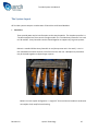
1
Torridon System User Manual Quarch Technology Ltd Torridon System User Manual For use with the Torridon System For Array Firmware version 4.x Friday, 22 February 2013 Revision 1.8 Quarch Technology 1 Torridon System User Manual Change History 1.4 2nd November 2010 Added Telnet control info 1.5 25 November 2010 Updated with new format common sections 1.6 7 September 2011 Updated with new PSU details 1.7 15 February 2012 Added NRTL Certification details 1.8 13 December 2012 Added additional disclaimers and usage warnings Revision 1.8 Quarch Technology 2 Torridon System User Manual Contents Change History ................................................................................................................................. 2 Operational Safety ........................................................................................................................... 7 Equipment Ratings.................................................................................................................................... 8 Environmental Conditions ........................................................................................................................ 8 Critical Notes ............................................................................................................................................ 9 Usage Scenarios ................................................................................................................................... 9 Mains Power Supply ............................................................................................................................. 9 Equipment Installation ........................................................................................................................... 10 Cleaning and Maintenance ..................................................................................................................... 10 Manufacturer Details.............................................................................................................................. 11 Declaration of Conformity ...................................................................................................................... 12 What does Torridon do? ................................................................................................................ 14 Where can I benefit from it? .......................................................................................................... 14 The System Layout ......................................................................................................................... 16 System Configuration ..................................................................................................................... 18 Bench Testing ......................................................................................................................................... 19 System Testing ........................................................................................................................................ 21 Chaining Array Controllers ................................................................................................................. 22 How to use the Control Modules ................................................................................................... 23 Module Architecture .............................................................................................................................. 24 Setting up hot-swap timing ................................................................................................................ 26 Choosing which signals to switch ....................................................................................................... 26 Timed Sources .................................................................................................................................... 27 Revision 1.8 Quarch Technology 3 Torridon System User Manual Special Sources ................................................................................................................................... 27 Setting up Pin Bounce ........................................................................................................................ 28 Controlling the System ................................................................................................................... 30 Serial Control .......................................................................................................................................... 31 Serial Port Configuration .................................................................................................................... 31 HyperTerminal Example ..................................................................................................................... 32 Commands .............................................................................................................................................. 33 Sending a Command .......................................................................................................................... 33 Bad Commands .................................................................................................................................. 34 Addressing Commands ....................................................................................................................... 34 Address List Format ............................................................................................................................ 35 Returns from Addressed Commands ................................................................................................. 35 Addressing a Port that does not exist ................................................................................................ 36 Soft Addressing .................................................................................................................................. 36 Other Terminal Features .................................................................................................................... 36 Ethernet Connection (Telnet) ................................................................................................................. 37 Connection ......................................................................................................................................... 37 USB Control............................................................................................................................................. 39 USB Drivers ......................................................................................................................................... 39 Default States ................................................................................................................................. 40 Array Controller ...................................................................................................................................... 40 Control Modules ..................................................................................................................................... 40 Classes of Control Module ............................................................................................................. 41 ‘How To’ Examples ......................................................................................................................... 42 Revision 1.8 Quarch Technology 4 Torridon System User Manual Perform basic checking........................................................................................................................... 42 Timing and Fault Injection Examples ...................................................................................................... 43 Perform a simple hot-swap on a drive module .................................................................................. 43 Simulate a failure during operation ................................................................................................... 44 Simulate pin bounce during a hot-swap ............................................................................................ 45 Measuring Voltages ................................................................................................................................ 46 Measure a Self Test Voltage ............................................................................................................... 46 Measure an External Voltage ............................................................................................................. 46 Glitching Examples.................................................................................................................................. 47 Line Driving Examples ............................................................................................................................. 47 Tips and Trouble Shooting ............................................................................................................. 48 Module plugged into array controller is not responding ....................................................................... 48 Module plugged into an Interface Card is not responding..................................................................... 48 A command returns a cursor, but no response ...................................................................................... 48 HyperTerminal works fine but my scripts don’t see the returns............................................................ 48 Appendixes..................................................................................................................................... 49 Appendix 1 - Command Listing ............................................................................................................... 49 Legacy Commands.............................................................................................................................. 49 Standard Commands .......................................................................................................................... 50 Appendix 2 - Error Codes ........................................................................................................................ 53 General error commands ................................................................................................................... 53 Hardware/Configuration based errors ............................................................................................... 53 Software based errors ........................................................................................................................ 53 Action based errors ............................................................................................................................ 53 Revision 1.8 Quarch Technology 5 Torridon System User Manual Appendix 3 - Glossary ............................................................................................................................. 54 Revision 1.8 Quarch Technology 6 Torridon System User Manual Operational Safety The Torridon System is designed solely for use by qualified personnel in a laboratory environment. Read the following limitations fully. Quarch Technology cannot be held liable for failure if the equipment is modified or operated in a fashion other than that specified below. Torridon is a modular system. This manual should be used in conjunction with the relevant Technical Manual for each of the system modules that you are using. The Torridon System as a whole is CE marked to the following standards: IEC61010-1:2001 (Low voltage directive) IEC61326-1:2005 (EMC Directive) The Torridon System is NRTL certified to the following standards: UL 60950-1:2007 CSA 22.2 No. 60950-1:2007 Revision 1.8 Quarch Technology 7 Torridon System User Manual Equipment Ratings Each Torridon Array Controller ships with a 12v, 60w DC power supply: Shipments before August 2011: Manufacturer: Model: Input: Output: Stontronics Ltd RDSA-60W-12-3 110-240v, 50/60Hz, 1.5A +12v DC, 5A Shipments after August 2011: Manufacturer: Model: Stontronics Ltd P/N: 3A-603DB12 3637EG Input: Output: 110-240v, 50/60Hz, 1.5A +12v DC, 5A These supplies are UL, CUL, GS, CB, CE, and FCC marked and were used during the certification of the Torridon system. Alternative supplies should not be used as this will invalidate the CE/UL marks and may cause undesirable effects. Environmental Conditions Operating Temp: Storage Temp: Operating Humidity: Storage Humidity: 5°C to 40°C (41°F to 104°F) 0°C to 45°C (32°F to 113°F) 20% to 80% (non condensing) 20% to 80% (non condensing) Quarch modules are not recommended for repeated temperature/humidity cycling. Modules used in this way may have a shorter operating life-span. Revision 1.8 Quarch Technology 8 Torridon System User Manual Critical Notes Usage Scenarios Quarch modules are intended for use in standard hardware. For instance, SAS drive modules are designed for use with a backplane and drive that complies with the SAS specification. Using the equipment in a system that does not meet the relevant specification may invalidate your warranty and could cause damage to the equipment. If you wish to use modules in any special test cases, please contact Quarch first so that we advise on the suitability of the test you wish to perform. Mains Power Supply Quarch modules may have a common ground within the entire test system. Care must be taken to ensure that all Quarch units and all the equipment under test is powered from the same phase. If a Serial/USB cable is used, the controlling PC/Terminal Server must also be on the same phase. This is most likely to be an issue in a large test lab, where 3-phase power is common. Revision 1.8 Quarch Technology 9 Torridon System User Manual Equipment Installation Due to its nature, operation of the system in a normal use-case may cause emission of RF interference. This is especially true if RF seals have been displaced in the system-under-test while fitting the Torridon interposer modules. In standard use the Torridon system should be run in a metal enclosed 19” rack cabinet with metal doors on both front and rear closed during operation. EMC testing was performed with the system in a Keyzone SX969 rack cabinet and this, or a similarly specified rack should be used at all times. The Array controller should be held in place by fitting standard rack fixings through the 4 holes on its front panel. Torridon interposer modules should be fitted with care into the system while all power is disconnected. The modules can only be used in systems that comply with the relevant interface specification. The interface specification used for each module is given in its Technical Manual. Care should be taken when routing the flex cables that connect the modules to the Array Controller. These cables can be damaged by sharp edges. After the setup is complete, the 12v power supplies may be attached. These should be powered by the standard 110-240v single phase supply as specified in the “Equipment Ratings” section. The power socket outlet shall be installed near the equipment and shall be easily accessible so that the unit can be easily disconnected from the mains supply in the event of an emergency. The addition of the interposer modules to a system under test may affect its airflow and cooling. This should be monitored carefully when the Torridon System is in use. The Array Controller may be mounted in the rack between 2 other standard pieces of equipment. No specific airflow requirements are needed so long as the ambient operating temperature is not maintained within the specified limits. Cleaning and Maintenance The Array Controller may be a dusted with a dry cloth. Water and alcohol based (or any other liquid) cleaners should not be used. Control modules cannot be cleaned. All parts of the system should be inspected before and after use. Special care should be taken to check for damage of the modules, module connectors and ribbon cables. Damaged components should not be used and cannot be repaired by the user. Please contact Quarch to arrange for repair. Revision 1.8 Quarch Technology 10 Torridon System User Manual Manufacturer Details The Torridon System is designed and manufactured by: Quarch Technology Ltd (registered in Scotland no: SC307569) Unit 3A, Myrtlefield Industrial Estate Aviemore UK PH22 1SB Web: www.quarch.com Email: [email protected] Phone: +44 1343 508 140 Revision 1.8 Quarch Technology 11 Torridon System User Manual Declaration of Conformity Manufacturers Name: Manufacturers Address: Quarch Technology Ltd 3A Myrtlefield Aviemore Inverness-shire UK PH22 1SB Declares under sole responsibility that the product as originally delivered Product Name: Torridon Test System Model Number: QTL1079, QTL1260 Product Options: Including all applicable control modules Complies with the essential requirements of the following European Directives, and carries the CE marking accordingly: Low Voltage Directive (2006/95/EC) EMC Directive (2004/108/EC) and conforms with the following standards: EMC Safety Standard Limit CISPR 11 BS EN 61000-3-2 BS EN 61000-3-3 BS EN 61000-4-2 BS EN 61000-4-4 BS EN 61000-4-5 BS EN 61000-4-6 BS EN 61000-4-11 Class A Class A Pass Pass Pass Pass Pass Pass IEC61010-1:2001 / EN 61010-1:2001 This DoC applies to above-listed products placed on the EU market after: June 06, 2010 Date Revision 1.8 Andrew Norrie Quarch Technology 12 Torridon System User Manual Revision 1.8 Quarch Technology 13 Torridon System User Manual Introduction The Torridon System from Quarch Technology provides a solution to considerably improve the testing of data storage arrays through automation. The system is simple to implement, highly scalable and extremely powerful. This manual is an introduction to the Torridon System and its main components. You should find everything you need to get started here, but for more detailed information please refer to the technical manual for the specific module you are using. If you can’t find what you need, please contact us. You can find our details and phone numbers on the web at www.quarch.com Alternatively, drop us a mail at: [email protected] What does Torridon do? The Torridon system allows removable components such as Disk Drives, RAID Controllers, IO Modules and Power Supplies to be inserted, removed and failed within a Data Storage System without human intervention and in a 100% programmable and repeatable manner. Where can I benefit from it? The Torridon System has a number of applications throughout the life cycle of a data storage system. Development As new products are developed, R&D engineers can benefit from a cheap and easy to use bench test setup. This allows you to test your system’s hot-swap performance and hardware level fault injection. Instead of manually hot-plugging a drive, you can automate the sequence with precise timing. This allows verification of boundary conditions, providing fast and highly comprehensive testing of hot-swap functionality. Fault injection is also greatly improved. Instead of physically altering hardware, broken circuit, stuck at ‘1’, short circuit and glitch faults can be created quickly and easily in a live system. Revision 1.8 Quarch Technology 14 Torridon System User Manual Running a sequence of tests after each change to software or hardware is essential to maintain quality and detect bugs before passing a release into system test. The Torridon System can greatly increase the speed, consistency and coverage of these tests. By removing the human element from hot-plugs and fault injection, a system can be tested more thoroughly and much faster. Removing human error and producing detailed logs also increases confidence in test results. Test When a product reaches the test phase, many tests are required over multiple releases, hardware revisions, drive revisions etc. Test engineers often spend a large dealing with manual and partially automated tests. Full automation delivers huge benefits in these large scale test scenarios. The Torridon “Lite” Control Modules are optimized for mass automation and provide an extremely rapid return on investment. Qualification As the reliability of storage systems is so critical, it is necessary to calculate the lifespan of each component. The ability of Torridon systems to perform rapid insertion and removals of drives is of benefit here Ongoing reliability testing, both in the lab and in environmental chambers can be made fully automatic. At least 10,000 insertion and removal cycles could be completed on a single drive within a week. RAID failover testing often involves running the system under heavy data load while performing a variety of hot-swap and failure events. In this way, you can see the effect of faults on a live system and how quickly it can recover from single or multiple drive failures. Revision 1.8 Quarch Technology 15 Torridon System User Manual The System Layout All Torridon systems comprise a combination of Controllers and Control Modules: Controllers These provide power and an interface point to the control modules. The simplest controller is a ‘Torridon Interface Card’ that controls a single module. The ‘Torridon Array Controllers’ can each run 28 modules. Array Controllers can be chained together to support very large test systems. Below is a standard 28 Port Array Controller in use (the top most unit in the stack). It is a 1U rack mounted unit and has 24 ports on the front and 4 on the rear. Multiple array controllers may be chained together to support larger systems Below is a much simpler configuration. A single 3.5” drive and control module is attached to an Interface Card, ready for bench testing. Revision 1.8 Quarch Technology 16 Torridon System User Manual Control Modules These sit between removable parts of the system under test such as a disk drive and back plane. They are transparent to the system and allow it to operate normally until a specific test is run. Below are a few of the available modules. All modules have an ultra-thin flex cable that is easy to route out of the enclosure. This cable provides all power and control for the Module From the left: 2.5” Drive Module, SBB Canister Module and 3.5” Drive Module. Our current range includes control modules for: SAS/SATA disk drives, SATA keyed Disk Drives and SBB canisters. Products in development will also add PSU and cable pull modules to the range. Revision 1.8 Quarch Technology 17 Torridon System User Manual System Configuration The Torridon System has two main configurations; bench test and system test. The choice between these is normally made according to the number of Control Modules you intend to use. It is possible to combine both configurations within your test system or even have multiple of each. It is simply a matter of deciding where the modules will be placed and how is best to cable them into your existing test environment. Revision 1.8 Quarch Technology 18 Torridon System User Manual Bench Testing Revision 1.8 Quarch Technology 19 Torridon System User Manual The bench testing configuration would involve perhaps one or two control modules, probably run from a PC where an engineer is operating them in real time. This mode is normally used for debugging faults in your system or boundary testing to find the failure limits of a design. Due to the small amount of equipment required this mode is ideal for evaluating the system and can still provide some major savings in cost and time. Set up the equipment as shown above. Any Torridon control module can be connected to the Interface Card. Setup details are also available in the appropriate “Quick Start Guide” for your Control Module. Each Interface Card can control one Control Module. If you have a large number of modules connected in this way then the cabling will rapidly become a problem! In this configuration, each module is controlled separately, through their own USB or Serial session. The disadvantage is the need to handle multiple control sessions. Also, it could be hard to synchronize the action of both cards exactly if you’re performing time critical testing. Revision 1.8 Quarch Technology 20 Torridon System User Manual System Testing Revision 1.8 Quarch Technology 21 Torridon System User Manual Setup the equipment as shown above. The 4 ports on the back of the Array Controller are positioned for connection to SBB or PSU Control Modules, however any Torridon control module can be connected to any port. Up to 28 modules can be connected to an Array Controller. If more ports are required, several Array Controllers can be chained together to form a much larger system. The Array Controller is designed to be as transparent as possible so it does not add extra complexity to the test system. This configuration allows large numbers of control modules to be controlled from a single interface. This will simplify your test setup and allow for faster and more accurately timed testing. This configuration is strongly recommended if you are using more than a few modules at a time and will also save the cost of the separate Torridon Interface Cards. Chaining Array Controllers Up to 4 Array Controllers can be connected together to provide a single point of control for many modules. To connect 2 Array Controllers, plug a standard RJ-45 patch cable (straight though) between the RS-232 OUT port of the first controller and the RS-232 IN port of the second. Repeat until all Array Controllers are linked. The green ‘link’ light should appear on each port to show that the connection has been made. You can now send commands to the first Array Controller as normal. See the ‘Address Mapping’ section below for the list of default addresses for the ports. Note that that by default, port 1 of the second array will be address ‘30’. See the ‘Array Controller Technical Manual’ for more details on addressing the modules and the use of ‘Soft Mapping’ to renumber the ports. Revision 1.8 Quarch Technology 22 Torridon System User Manual How to use the Control Modules All Torridon Control Modules have the same basic architecture, a combination of Power, Data and Logic pins are connected from the male connector to the female connector through a switch. Each switch can be individually turned on or off immediately, or after a set delay time, giving the user full control over the pin connection timing. This allows the user to remotely remove and insert a drive, emulate hardware failures, or program precise and 100% repeatable hot-plug scenarios. Please see the relevant datasheet or technical manual to determine which pins are switched on a specific control module. Any pins without switches are routed directly through the card. This means that when all the switches are closed, the control module is completely transparent to your system. Revision 1.8 Quarch Technology 23 Torridon System User Manual Module Architecture There are two main ways to use the module 1) Set up a timing pattern that will be executed later, on running the command “power up”. This allows you to simulate precise hot-swap events. To do this you must specify a timing sequence then choose which of the switches will change at each point in the sequence. Example: hot-plug (drive insertion) event 1. Setup Control Sources Source 0 OFF Source 1 10mS Delay Source 2 25mS Delay Source 3 50mS Source 4 100mS Source 5 70mS Source 6 30mS Source 7 INSTANT CHANGE 2. Assign signals to Control Sources 12v Charge Switch 5v Charge Switch 12v Power Switch 5v Power Switch 3. Run “power up” or “power down “ command to activate 12v Charge 5v Charge 12v Power 5v Power 0mS 10mS 25mS In this example, a 2 stage hot-plug is performed. The 5v and 12v power pins are connected 15mS after the 5v pre-charge pin has been connected, the 12v pre-charge signal was left unconnected. Revision 1.8 Quarch Technology 24 Torridon System User Manual 2) Manually open or close switches. This allows you to create real time faults in the system. It can also be combined with timed hotswap events. For instance, you could perform an automated hot-swap then manually open one of the switches to create a failure. Example: manual fault injection (Performed after the above hot-plug event was run) Source 0 OFF Source 1 10mS Delay Source 2 25mS Delay Source 3 50mS Source 4 100mS Source 5 70mS Source 6 30mS Source 7 INSTANT CHANGE 2. Switches may be assigned to Sources in real time 12v Charge Switch 5v Charge Switch 12v Power Switch 5v Power Switch 1. Moving the Source assignment causes the switch to change instantly 12v Charge 5v Charge 12v Power 5v Power In this example, the setting of the 5v pre-charge signal has been changed. It has now been assigned to Source 0. This is a special source that is always off. Any signal assigned to source 0 is always disconnected. Revision 1.8 Quarch Technology 25 Torridon System User Manual Setting up hot-swap timing Modules have a set of numbered “sources” that control the operation of timed hot-swaps There are two types of sources, “timed sources” and “special sources”. Special sources always perform the same action and have no settings. Timed sources have parameters that must be set up in advance. When you want to perform a timed hot-swap event, you must setup the timed sources then assign each signal to a source. If multiple signals are assigned to the same source then they will be switched in exactly the same way. Finally a command is issued to begin the hot-swap event. The table below shows an example set of sources; some modules have different source configurations that will be listed in their technical manual. Source Number 0 1 2 3 4 5 6 7 8 Description Signals are always off Timed source 1 Timed Source 2 Timed Source 3 Timed Source 4 Timed Source 5 Timed Source 6 Signals change instantly at the start of the timed event Signals assigned to this source are always connected The timed sources of most modules require one initial delay and three pin-bounce parameters. The diagram below shows how these parameters affect the state the source after the hot-swap begins. Any signals that are assigned to this source would connect and disconnect in exactly the same pattern. Choosing which signals to switch Control Modules have a link between each pin on one side to the matching pin on the other. Some of these links can be broken by switches on the module. These are referred to as “switched signals” or just “Signals”. When you have set up the source parameters for the hot-swap event, you must choose which signals will be assigned to each source. Each signal has a parameter that defines the number of the source it will use. Each signal is referenced by its name, normally corresponding to the industry specifications. Each signal also has a numeric setting that assigns it to a control source on the module. This setting is defined in the Revision 1.8 Quarch Technology 26 Torridon System User Manual signals control register and defines how and when the state of the signal switch will change. Every signal that is assigned to the same source will behave in exactly the same way. Changing a signal from one source to another will cause the switch state of the signal to immediately change to match the state of its new source. For example: moving a signal from source 8 to source 0 will cause it to be disconnected, this might be done to simulate a fault occurring. Timed Sources Timed sources are normally numbered 1 to 6. These are used to create a staged hot-swap event. This is where some pins are connected before others, to simulate differences in the length of connector pins. Timed sources have an initial delay that describes how long they should wait after the user sends a power up/power down (hot-swap) command. After this time completes, the source activates. When active, all signals that have been assigned to the source are connected. A timed source may also have simulated pin bounce. After the initial delay, a set of defined bounces can simulate the physical contact bounce when a plug is inserted. Special Sources Sources 0, 7 and 8 are special purpose sources. A signal that is assigned to Source 0 will be disconnected at all times. A signal that is assigned to Source 7 will change immediately, at the moment the power up/power down command is run. The signals will be connected on power up and disconnected on power down A signal assigned to source 8 will always be connected, regardless of the hot-swap state. Revision 1.8 Quarch Technology 27 Torridon System User Manual Setting up Pin Bounce Pin Bounce can be set in two ways: 1) Basic Pin Bounce: a. b. c. d. (This is the default mode) Delay (TDELAY) 0 to 1s (0-100mS @ 1mS increment or 0.01s to 1s @ 10mS) Bounce Period (Period) 0 to 100mS (0-1000us @ 10uS increment or 0-100mS @ 1mS) Bounce Length (Tdelay) 0 to 1s (0-100mS @ 1mS increment or 0.01s to 1s @ 10mS) Bounce Duty Cycle (On %) 0 to 100 % Hot-Swap State BOUNCE PERIOD DELAY Revision 1.8 BOUNCE DUTY CYCLE BOUNCE LENGTH Quarch Technology 28 Torridon System User Manual 2) Custom Pin Bounce: a. b. c. d. (set Sx_PIN_BOUNCE_MODE = 1) Delay (TDELAY) (0-100mS @ 1mS increment or 0.01s to 1s @ 10mS) Bounce Period 0 to 100mS (0-1000us @ 10uS increment or 0-100mS @ 1mS) Bounce Pattern (Pattern) up to 104 bits Bounce Length (0 to 100ms @ 1mS increment or 0.01s to 1s @ 10mS) Hot-Swap State BOUNCE PERIOD CONTROL SOURCE DELAY BOUNCE LENGTH 1 0 1 1 0 0 1 11 Custom Pin Bounce Pattern 0 Pattern Currently, custom pin bounce must be set up by using the register write commands. Check the technical manual for the location of the Sx_PIN_BOUNCE_MODE bit that must be set. You will also need to write your custom pattern into the registers. Revision 1.8 Quarch Technology 29 Torridon System User Manual Controlling the System These are several options for controlling the Torridon System. Depending on your configuration, these include: Serial from a terminal window Serial from an automated script USB Telnet (Telnet functionality is expected to be available in Q2 2010) Serial control is the default communications mode. Only one method of communication can be used at a time. If you open a Telnet or USB session to the device then serial will stop responding. It will restart again when you disconnect the session. If a USB session is open then you will not be able to connect via Telnet and vice versa. The serial command “config:comms:lock on” will prevent a USB or Telnet session from taking over control of the system. This is useful when you are running an important test that should not be interrupted! In the majority of cases, serial control from an automated script (such as PERL) or a programming language (C, C#, etc) is used to control the system as this allows full automation without human intervention. USB control is mainly used in bench testing when combined with the TestMonkey graphical control suite. Revision 1.8 Quarch Technology 30 Torridon System User Manual Serial Control The most common method of control is via a standard serial port. Both the Array Controller and the Interface Card have DB-9 and RJ-45 serial connectors. These are wired together so only one should be connected at a time. Serial Port Configuration All Torridon devices use the same serial port configuration: 19,200 Baud 8 Bit data 1 Stop bit No Parity The Array Controller also supports hardware handshaking. If you are using a control module via a Torridon Interface Card then handshaking should be set to ‘None’ By default, the system will echo typed characters so you should disable your terminal program from echoing them locally. When using an Array Controller, you will always be using a serial connection. Revision 1.8 Quarch Technology 31 Torridon System User Manual HyperTerminal Example In this example, the screenshot shows the start screen of an attached 3.5” SAS/SATA Drive Control Module. This screen is displayed at power-up, reset, and any time enter is pressed without a command being typed. Note that the self test is marked as ‘passed’, showing its internal functions are working correctly. Revision 1.8 Quarch Technology 32 Torridon System User Manual Commands Sending a Command When ready, you will see the prompt “>”. This indicates that it is OK to send a command. Type the command and press enter. The command will execute and return a result. The responses are kept very simple to aid parsing when using automated scripts. Some responses will return over multiple lines. No response line will be longer than 64 characters. Commands are not case sensitive. Many commands have a shorter version made up of just the first few characters for faster typing. Once the response is complete, the cursor “>” will be displayed on a new line, indication we can send the next command. Most commands will execute in between 10-100mS although some special commands on the Array Controller may take several seconds to complete. No command can be longer than 64 characters, if this limit is exceeded you will get an error message. The serial command set is a hierarchy, similar to the standard SCPI specification. Sections of the command are separated by a “:”, and a “?” at the end indicates you are querying a setting or measurement. Commands are not case sensitive and most command sections have a shorter version (for example “Config” can be shortened to “Conf” Examples: Source:1:delay 27 Source:1:delay? Source:1:bounce:duty 50 Source:1:bounce:period 300 Sets the source 1 initial delay to 27mS Queries the source 1 initial delay value Sets the pin bounce duty cycle of source 1 to 50% Sets the pin bounce period of source 1 to 300uS See the Appendix for a list of commands Revision 1.8 Quarch Technology 33 Torridon System User Manual Bad Commands If a command is typed incorrectly, an error will be returned. This will be in the form: FAIL: 0xnn -Failure Message Where 0xnn is a hex number representing the error code (for easy parsing) and the failure message is an easy to read description of the problem. You can turn off the descriptive part of the failure message to ease parsing (using the “Config:Messages short” command). Addressing Commands When using an Array Controller, any command can be addressed to a specific device. To do this, we append an ‘Address List’ to the end of the command. For example: run:power up Becomes: run:power up <7> The first example would be used with an Interface Card and a single control module. The second would be used with a control module that is connected on port 7 of an Array Controller. When using an Interface card with a single control module, address lists are not required although the module will also respond to any command that includes address ‘0’. Any other address will be ignored. When using an Array Controller, a command without an address list will be executed by the Array Controller itself. This would be used be used if you want to setup or query options on the controller. Normally you will want to address the attached modules. This is when we need an address list. Revision 1.8 Quarch Technology 34 Torridon System User Manual Address List Format Using an address list, you can control multiple modules at the same time. This is very useful when timing is critical (such as pulling 3 drives at the exactly the same time) and to speed up the setup of a group of control modules. Address lists are enclosed in angle brackets “<>” and contain a series of parts, each separated by commas. A part can be either a single address such as “7” or a range, such as “2-6”. The following command would return the version of modules on ports 1,3,4,5 and 10 Version <1 ,3-5,10> The addresses “3” and “3.0” both refer to the module on port 3 and either may be used. The number after the decimal point is used internally in the system and will not normally be required by the user The only limitation on address lists is that the entire length of the command must not be longer than 64 characters. Returns from Addressed Commands If you send a command with an address list, there may be multiple responses from the different modules. To identify these, each response line of an addressed command has the module number at the start. For example, if we send the command Reg:read 0x00 The response is “0x01” or similar If we send the command with an address list: Reg:read 0x00 <3,4> The response is 3.0:0x01 4.0:0x00 Revision 1.8 Quarch Technology 35 Torridon System User Manual Addressing a Port that does not exist If you send a command to port <20> and there is nothing attached on that port, then the following error will be returned: 20.0:FAIL 0x26 -No device is attached to this port > The error message will only be sent if the addressed port is physically present in the system. If you have a single Array Controller and do not have soft mapping enabled you will see a response from port 12 which is physically present, but no response from port 33. On connecting a second array controller you would also begin receiving error messages from port 33. On a single Array Controller in hard mapped address mode, the command “Reg:read 0x00 <10,33>” would return: 10.0: 0x00 > Port <10> responds but port <33> does not exist in the system and so has no response. Soft Addressing Sometimes it is not possible to cable the drive you prefer to call number 1 into port 1 on the Array Controller. In this case you can use ‘soft addressing’ This allows you to setup a mapping table on the Array Controller that will route any command you send to address 1, to the actual port that drive 1 is attached to. See the “Array Controller Technical Manual” for full details on this feature Other Terminal Features Backspace will delete the last character typed Pressing ‘Tab’ on an empty line will retype the last command Any command starting with a ‘#’ will be interpreted as a scripting comment and be ignored Revision 1.8 Quarch Technology 36 Torridon System User Manual Ethernet Connection (Telnet) Control via a Telnet terminal works in exactly the same way as the serial terminal described above. Only one Telnet connection to the unit can be made at a time, further connections will be refused. An active Telnet connection will also lock out the serial terminal as only one connection can be active at a time. If you want to prevent a Telnet connection from taking over control from the serial terminal, you can use the command: “conf:terminal:lock on”. See the Array Controller Technical Manual for more details Connection To use Telnet, connect the Array Controller to your network using an RJ-45 cable into the “ETHERNET” port on the rear of the unit. The Array Controller requires a DHCP server to obtain its IP address. If one is not available, the Ethernet connection will not work. Once connected, you can obtain the IP address using the command “conf:ethernet:ip?” from the serial terminal. The Array Controller also supports NETBIOS names. The name of the unit is based on it’s serial number. This can be found on the rear of the unit in the form: “QTL1079-xx-xxx”. The NETBIOS name will be: QTL1079 – 28 Port Array Controller: QUARCH-T-xx-xxx Where xx-xxx is the last digits of the serial number. QTL1461 – 4 Port Array Controller QTL1461-xx-xxx Where xx-xxx is the last digits of the serial number. Connection to the Telnet terminal should be on Port 23 in the connection settings of your terminal program. Revision 1.8 Quarch Technology 37 Torridon System User Manual Revision 1.8 Quarch Technology 38 Torridon System User Manual USB Control Both the Array Controller and the Interface card have a USB (Type B) socket. Most standard Torridon control modules support USB with the exception of the ‘Lite’ Modules. When attached to an Array Controller, modules are all connected via an internal USB hub. The main use for the USB connection is for control via the TestMonkey application. This allows a module to be controlled graphically, making it easier to setup and understand the precise timings for complex tests. Control via TestMonkey is normally used in bench test or fault finding scenarios. The USB connection is also used to allow firmware update of the control modules. This allows users to quickly upgrade their system when new features become available. When you connect to a device via USB using TestMonkey or similar, it will not be possible to communicate with it by serial or any other mode until you end the USB session. USB control uses the Quarch command API to send binary commands. It does not use text commands the way Serial or Telnet does. USB control of a module is normally done via an Interface Kit when bench testing. USB control of a large number of devices via a Torridon Array Controller is not recommended as the host PC may become unstable when so many USB devices are attached at the same time. USB Drivers The first time you connect a USB device, you will be prompted for the drivers. These are available from the download section of the Quarch website (www.Quarch.com). Chose the option to locate the driver manually and select the location where you downloaded the drivers to. Revision 1.8 Quarch Technology 39 Torridon System User Manual Default States On power up or reset, devices enter a default state. All user settings are cleared. Array Controller Default port mapping (Soft Mapping is off) so ‘port 1’ is addressed as ‘1’ etc Default terminal mode (Optimized for use with HyperTerminal or similar) Error messages are returned in full Control Modules Default terminal mode (Optimized for use with HyperTerminal or similar) Error messages are returned in full All sources are enabled A simple and realistic hot-swap timing scenario is loaded so that a basic hot-plug can be performed without making any changes to the settings Pin bounce duty cycle (if available) is set to 50% Revision 1.8 Quarch Technology 40 Torridon System User Manual Classes of Control Module There are several classes of control module available. The classes are not entirely different in terms of their features, but give a good indication of the purpose and abilities of the module. Standard Control Modules These modules have no special class name. They include our original range of Torridon control modules. Features include: USB control, Hot-swap and pin-bounce simulation, voltage measurement and high-spec solid state switches. High speed SAS data signals cannot be switched. High Speed Control Modules (Designated ‘HS’) These modules have all the features of the standard modules but can also switch high speed SAS data up to 6Gbit/s. They can also glitch signals to inject errors into the system. Lite Modules Lite modules were designed with cost as a priority. They are intended for use in large test environments such as QA where mass automation is required. These modules do not have pinbounce simulation or USB control and have cheaper solid state switches. However they can perform many of the same tests as standard modules and are optimized for cost when bought in larger quantities. Cable Pull Modules These are metal cased units that have an ‘in’ and ‘out’ cable socket. The module is plugged inline between the host and device allowing the cable to be hot-plugged or interrupted in the same way that the High Speed Control Modules allow. Current cable-pull modules include: USB 3.0, Mini SAS, mini SAS HD, eSATA and Ethernet (RJ-45). Mux / Physical Layer Switch Modules These modules allow signal routing between multiple devices to be automatically configured. This could include switching multiple USB devices into a host in turn, or switching a SAS analyzer in to a signal path. Each switch module has a different number of ports, depending on its purpose and the requirements of the signals being switched. Some modules can be run ‘standalone’ (can be used without an interface kit or array controller). Programmable Power Modules Power modules are advanced power supplies. All can output accurate voltage levels for power margining, and most also perform ramps, glitches and complex patterns. The modules can also measure power/current/voltage levels and some can capture output waveforms. Revision 1.8 Quarch Technology 41 Torridon System User Manual ‘How To’ Examples Some of these examples are written as if an Array Controller with several attached control modules is being used. If you are using a single module with an Interface Card then simple remove the address lists from the command (the <1,2,3…> section at the end of each command) Perform basic checking *RST Reset the device (or entire system when using an Array Controller). All settings are cleared *TST? Runs a test of the device and returns the results (when run on an Array Controller, tests only the controller, not the attached modules *IDN? Return the part numbers and versions of the attached device for identification Revision 1.8 Quarch Technology 42 Torridon System User Manual Timing and Fault Injection Examples Perform a simple hot-swap on a drive module First we have to set up the timing characteristics to use (in which sequence and at what time to connect each signal) For this example we will do a three stage hot-plug on a standard Drive Control Module on; allowing precharge and power signals to be connected before the Mated signals that the drive is ready. This should produce a nice, clean hot-plug. Set source 1 initial delay to 0mS, source 2 initial delay to 10mS and source 3 to 25mS Source:1:delay 0 Source:2:delay 10 Source:3:delay 25 Set all the pre-charge pins to source 1, power pint to source 2 and mated to source 3 Signal:3v3_charge:source 1 Signal:5v_charge:source 1 Signal:12v_chance:source 1 Signal 3v3_power:source 2 Signal 5v_power:source 2 Signal 12v_power:source 2 Signal:special1:source 3 Now run the hot-plug Run:power up To power down the drive, we perform a hot-pull. This will run each timed action in reverse (mated will be disconnected before power, etc) Run:power down If the module you are using is connected to an Array Controller then each command will also require an address map. If the module was on port 6 then <6> would be appended to each command. For example: Run:power up <6> Revision 1.8 Quarch Technology 43 Torridon System User Manual Note that the power up/down command will fail if you attempt to power up a drive that is already powered. The OK/FAIL response from these commands only indicates that the hot-swap sequence started correctly. It does not in any way check if the drive actually powered up or is working. This should be confirmed through your normal diagnostic methods. Note that the cursor may be returned BEFORE the entire action has been completed if the hot-swap timing sequence is very long. Most control modules have a ‘Busy’ flag that can be read back to see if a long hot-swap action is still in progress. If you want a different power down timing sequence from the power up timing, you can alter the source and or signal settings while the drive is powered. Simulate a failed track or bent pin This is done to simulate a hot-plug where one or more signals do not connect. This would happen if a pin was bent or a track was broken. Set up a hot-plug event as above but connect the ‘broken’ pin to source 0 Signal:5v_power:source 0 Run:power up On power up, the 5v power signal will not be connected; this may cause an error as the power supplied by the 5v Pre-charge pin may not be enough to run the drive. Query the DUT to see that the failure was seen and handled correctly Simulate a failure during operation This is a ‘fault injection’ test, done to see how the system responds to a component failure. Setup a basic hot-plug as above and power up the device under test When it is running normally, we disconnect one of the signals to simulate a failure Signal:12v_power:source 0 Query the DUT to see that the failure was seen and handled correctly Revision 1.8 Quarch Technology 44 Torridon System User Manual Simulate pin bounce during a hot-swap Pin bounce can be added to any timed source. It can be set up in a single command or as separate steps In this example we will setup a bounce configuration on source 3 using a ‘bounce length’ or 3mS, a ’bounce period’ of 300uS and a ‘duty cycle’ of 70%. Setting up in a single command. Source:3:bounce:setup 3,300,70 Setting up as separate parameters Source:3:bounce:length 3 Source:3:bounce:period 300 Source:3:bounce:duty 70 Note that no units are used here. These commands all have a single fixed unit (mS for length, uS for period and % for duty cycle). In some cases resolution is limited and the exact value you specify is not available. In this case, the next nearest value will be used. Revision 1.8 Quarch Technology 45 Torridon System User Manual Measuring Voltages Modules have two forms of voltage measurement: Self test measurements to confirm the unit is operating correctly External measurements to see how your hardware is operating All voltage measurements are returned in milliVolts Measure a Self Test Voltage Request the 5 Volt and 12V measurements on a control module. Note that some modules support different voltage measurements, depending on their hardware. You should look up the relevant Technical Manual or the ‘help’ screen on the module to find the supported voltages. All internal voltages are tested on startup as part of the self test process. Measure:voltage:self:5v? Measure:voltage:self:12v? Measure an External Voltage Note that some modules (especially SBB modules) support different measurements. See their Technical Manual for details. Request the 5v ‘input’ voltage on a Drive Control Module. This monitors the 5 Volts supplies by the backplane drive slot: Measure:voltage:5vin? Request the 5v ‘out’ voltage on a Drive Control Module. This monitors the 5 Volts output from the control module to the disk drive. The level can be different from the input voltage if the module is set to disconnect the 5 volts line: Measure:voltage:5vout? Revision 1.8 Quarch Technology 46 Torridon System User Manual Glitching Examples QTL1177 (2.5” HS Drive Control Module) contains a high speed glitching module. This allows a single glitch (or a series of glitches) to be made on one or more signals. This can be used to corrupt SAS data, add noise to power lines etc. Please see the appropriate Technical Manual for full details Line Driving Examples QTL1160 (SBB 2.0 LD Canister Control Module) has a line driving module. This allows signals to be pulled high or low to simulate various short circuit conditions. In order to prevent damage to your system, signals are disconnected before being driven. For example: A signal that is an output from the backplane to the SBB canister will be disconnected on the backplane side first. The SBB side will then be driven to the specified level, ensuring that there is no risk of shorting out the backplane. The driving feature enables a greatly increased number of fault injection tests in comparison to the standard SBB module. Please see the appropriate Technical Manual for full details Revision 1.8 Quarch Technology 47 Torridon System User Manual Tips and Trouble Shooting Module plugged into array controller is not responding 1. Check the module is correctly plugged with the while ‘Pin 1’ arrows aligned 2. Reset the Array Controller by pulling its power. Check the port lights all flash at startup 3. Re-plug the module and check the green light on the port turns on (this may take up to 10 seconds) 4. Send the ‘help’ command to the Array Controller to check the Comms link to it is working 5. If there is no light, try it in a different slot 6. If this still fails, try testing it with a Torridon Interface Card or contact us for help Module plugged into an Interface Card is not responding 1. Check the two green power LEDs on the Interface Card are lit 2. Check the module is correctly plugged with the while ‘Pin 1’ arrows aligned 3. Check the serial cable is correctly installed. Cables you have in the lab may not match the pinout of the DB-9 to RJ-45 cable supplied by Quarch. A command returns a cursor, but no response 1. Check you have used the correct address list on the command. If you send a command to a port number that does not exist, you will not get any response. HyperTerminal works fine but my scripts don’t see the returns 1. Some (especially Linux) based serial ports buffer lines of data until a <CR> is seen. If you are waiting for the cursor, you might not see it until after the NEXT command has been sent! 2. Set mode (config:terminal script) to make things easier. This will disable remote character echo and add <CR> <LF> after every cursor, making it easier to parse responses Revision 1.8 Quarch Technology 48 Torridon System User Manual Appendixes Appendix 1 - Command Listing The following lists shows all standard commands used on the Torridon System. Note that not all commands are available on all devices. For more details on each command and its actions, please see the appropriate Technical Manual. Legacy Commands These commands were built into early versions of the Torridon system and most are still provided in the newer cards to ensure compatibility with existing scripts. [0xAA] = Hex register address [0xDD] = Hex data value Read 0xAA Returns the value of the given register address in Hex Read 0xAA to 0xAA Returns a list of values between the given register range Write 0xAA 0xDD Writes the given register address with the given value in Hex Power up Starts a timed hot-swap ‘plug’ operation Power down Performs a times hot-swap ‘Pull’ operation Voltage NAME Measures the given voltage item Revision 1.8 Quarch Technology 49 Torridon System User Manual Standard Commands These commands are loosely based on the ‘SCPI’ standard. They are NOT case sensitive and are arranged in a hierarchy where each section of the command is separated by a ‘:’. Most command sections have a shorter version quicker typing. The command ‘measure’ is written here as ‘MEASure’. This shows that you can use the entire word or just the ‘meas’ section. Commands that end in a ‘?’ are queries that will fetch a result from the module. This could be when requesting a voltage measurement or getting the current state of a setting. Note that not all commands are available on all modules. Check the individual technical manuals for full details. [0xAA] = Hex register address. Some Modules use 16 bit addressing (0xAAAA) [0xDD] = Hex data value, Some Modules use 16 bit data (0xDDDD)[H] = Hard addressed port number (decimal integer) [S] = Soft addressed port number (decimal integer) *RST *CLR *IDN? *TST? Resets the current device Clears the terminal screen but does not change any settings Returns identifying information and versions for the device Runs a set of internal tests on the device REGister:READ 0xAA REGister:DUMP 0xAA 0xAA REGister:WRITe 0xAA 0xDD Reads a value from the give register address in Hex Returns a list of values between the given register range Writes the given register address with the given value in Hex CONFig:MODE BOOT CONFig:TERMinal USER CONFig:TERMinal SCRIPT CONFig:TERMinal:LOCK ON CONFig:TERMinal:LOCK OFF Starts the bootloader to firmware can be updated Default mode for HyperTerminal etc Better for scripting, does not echo transmitted characters Locks device control to the serial terminal, preventing other access Releases the terminal lock CONFig:MESSages SHORT CONFig:MESSages USER Error responses and messages will be shorter, for easier parsing Error responses will be set to default with full descriptions CONFig:MAPping:WRIte H S CONFig:MAPping:READ H CONFig:MAPping:DUMP H H CONFig:MAPping:ACTivate CONFig:MAPping:RESet Alters soft mapping table, placing soft address S in position H Returns the soft mapping number in position H Returns a list of soft mapping number between the given range Activates the current mapping table (slow command) Resets then activates the mapping table (slow command) Revision 1.8 Quarch Technology 50 Torridon System User Manual CONFig:MAPping:MODE HARD CONFig:MAPping:MODE SOFT CONFig:MAPping:MODE? CONFig:MAPping:FLAsh S Ports are hard addressed (default on power up) Ports are soft addressed (set automatically on mapping activation) Returns the current mapping mode Flashes the port light of the given soft address, helps find the port CONFig:ETHernet:SNTP ON CONFig:ETHernet:SNTP OFF CONFig:ETHernet:SNTP? CONFig:TIME? CONFig:ETHernet:IP? Activates the SNTP client Deactivates the SNTP client Gets the state of the SNTP client Returns the current time Returns the current IP address MEASure:VOLTage NAME? MEAS:VOLTage:SELF NAME? Returns the named test voltage measurement Returns the named self test voltage RUN:POWer UP RUN:POWer DOWN RUN:GLITch ONCE RUN:GLITch CYCLE RUN:GLITch PRBS RUN:GLITch OFF Starts a hot-swap ‘Plug’ sequence Starts a hot-swap ‘Pull’ sequence Triggers a single glitch Starts a simple repeating glitch sequence Starts a PRBS repeating glitch sequence Stops any repeating glitch sequence SOURce:[1-6]:STATE ON SOURce:[1-6]:STATE OFF SOURce:[1-6]:STATE? SOURce:[1-6]:DELAY N SOURce:[1-6]:DELAY? SOURce:[1-6]:BOUNce:LENgth N SOURce:[1-6]:BOUNce:LENgth? SOURce:[1-6]:BOUNce:PERiod N SOURce:[1-6]:BOUNce:PERiod? SOURce:[1-6]:BOUNce:DUTY N SOURce:[1-6]:BOUNce:DUTY? SOURce:[1-6]:BOUNce:CLEAR SOURce:[1-6]:BOUNce:SETup Enables the given timed source Disables the given timed source Returns the enable state of the given timed source Sets the initial delay of the source to N mS Returns the initial delay of the source Sets the pin-bounce length to N mS Gets the pin-bounce length Sets the pin-bounce period to N uS Gets the pin-bounce period Sets the pin-bounce duty cycle to N % Gets the pin-bounce duty cycle Resets all pin-bounce parameters to default (off) Sets up all pin-bounce parameters in a single command SIGnal:[NAME]:SOURce N SIGnal:[NAME]:SOURce? SIGnal:[NAME]:DRIVe:ENAble ON SIGnal:[NAME]:DRIVe:ENAble OFF Sets the source that the signal is assigned to Gets the source that the signal is assigned to Activates line driving for the signal Deactivates line driving for the signal Revision 1.8 Quarch Technology 51 Torridon System User Manual SIGnal:[NAME]:DRIVe:ENAble? Returns the enable state for line driving for the signal SIGnal:[NAME]:DRIVe:LEVel HIGH Sets line driving for the signal to drive high SIGnal:[NAME]:DRIVe:LEVel LOW Sets line driving for the signal to drive low SIGnal:[NAME]:DRIVe:LEVel? Gets line driving level for the signal SIGnal:[NAME]:DRIVe:DIRection IN Sets line driving direction for the signal to out SIGnal:[NAME]:DRIVe:DIRection OUT Sets line driving direction for the signal to in SIGnal:[NAME]:DRIVe:DIRection? Gets the line driving direction for the signal SIGnal:[NAME]:GLITch:ENAble ON SIGnal:[NAME]:GLITch:LEVel HIGH SIGnal:[NAME]:GLITch:LEVel LOW SIGnal:[NAME]:GLITch:LEVel? SIGnal:[NAME]:GLITch:DRIVe ON SIGnal:[NAME]:GLITch:DRIVe OFF SIGnal:[NAME]:GLITch:LEVel? Connects the signal to the glitch generator Sets line driving mode during a glitch to high Sets line driving mode during a glitch to low Gets the line driving mode during a glitch Sets line driving enable during a glitch to on Sets line driving enable during a glitch to off Gets the line driving enable state when glitching GLITch:MULTiplier SETTING GLITch:LENgth N GLITch:LENgth? GLITch:CYCle N GLITch:CYCle? GLITch:PRBS SETTING GLITch:PRBS? Sets the glitch length multiplication factor to one of a set of values Sets the glitch length value to N Gets the glitch length time (as multiplier * Length) Sets the repeat cycle length for a repeating glitch sequence Gets the repeat cycle length for a repeating glitch sequence Sets the PRBS pattern type for repeated glitching Gets the PRBS pattern type for repeated glitching Revision 1.8 Quarch Technology 52 Torridon System User Manual Appendix 2 - Error Codes The following error codes are used throughout the Torridon system: General error commands 0x11 Bad command, probably an incorrectly spelt command section 0x12 Too many arguments in the command 0x13 Too few arguments in the command 0x14 Incorrectly formatted HEX argument (must be in the form “0x3B”) 0x15 Bad argument, command argument is not valid 0x16 A numeric value in the command is outside its valid range 0x17 A named object (e.g. signal name) is invalid 0x18 The length of the command is wrong (for commands with a fixed data length) 0x19 The command is too long to be processed 0x1A One or more addresses in the address list are not in the correct format Hardware/Configuration based errors 0x20 Generic hardware error (device may be faulty) 0x21 The command references hardware that does not exist in this device 0x22 The requested measurement (e.g. voltage measurement) is not available on this device 0x23 Register write failed to verify (may be faulty HW or writing to a read-only register) 0x24 Response timed out (A device failed to respond and may have crashed) 0x25 The requested port address is not in the current mapping table 0x26 The requested port does not have a device attached to it 0x27 The requested port is powered down so cannot process commands 0x28 Comms is locked to USART so commands cannot be executed on this terminal 0x29 Comms is locked to USB so commands cannot be executed on this terminal 0x2A Comms is locked to TELNET so commands cannot be executed on this terminal 0x2B Command is not supported on this device Software based errors 0x30 Generic software error 0x31 Current bootloader version does not support the command Action based errors 0x40 An programmed action failed to complete correctly 0x41 The action failed as the device was already in the requested state Revision 1.8 Quarch Technology 53 Torridon System User Manual Appendix 3 - Glossary Torridon Control Module Array Controller Interface Card Source Timed Source Signal Special Sources State Revision 1.8 The name of the overall system from Quarch. This comprises of Control Modules, Array Controllers and software applications These are the interposer modules that sit between critical parts of the system (such as between a drive and the back plane). They require external power and control This is the central hub of the system, providing power and control to a number of Control Modules A simple card, providing power and control connections for a single Control Module. It normally provides input for a power supply and USB/Serial cable connections Sources are found on Control Modules where they are used to control the action of Signals. Sources can have parameters such as Initial Delay (See also Timed Sources). Other Sources have fixed setting (See also Special Sources) These are sources that allow a Hot-Swap action to be run. They are programmed in advance with parameters such as Pin Bounce and Initial Delay. When a Hot-Swap action is started. The Timed Sources change State in a precise pattern. Any Signal that is attached to the Source will also change state at exactly the same time Signals (or Switched Signals) refer to the connection between a pair of connector pins on the Control Module. These connections can be mode or broken (and in some cases also driven high or low) on demand. Each Signal has a setting for the Source that it is attached to. The state of the Signal will follow the state of the Source. Depending on the Control Module, some Signals may have a number of extra settings These are a special type of Source that does not have timing parameters that you can change. Examples: An ‘Always Off’ source which is always in the disconnected State An ‘Immediate Change’ source will change instantly that you begin a hot-swap action Signals and Sources both have a State. The State of the Signal will always match the state of the Source that it is assigned to. The state refers to how the connector pins of the Signal are affected. Standard States include: Connected: The pins are joined as if the control module was not there Disconnected: The pins are open circuit Driven High: The output side pin is driven to Vcc Quarch Technology 54 Torridon System User Manual Hot-Swap DUT Plug Pull Revision 1.8 Driven Low: The output side pin is driven to Vdd A Hot-Swap is an action where one part of the DUT is inserted or removed while the system is powered and running. Control Modules can simulate HotSwap without having to physically remove the device from the system. During a Hot-Swap, each Signal is connected or disconnected in sequence. The sequence is based on the relative lengths of the pins in the connector. Device Under Test. This is the customers system that the Torridon Modules are attached to. A Hot-Swap when a device is inserted into a system, causing it to power up without warning A Hot-Swap when a device is removed into a system, causing it to power down without warning Quarch Technology 55