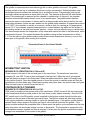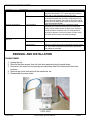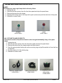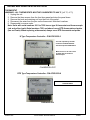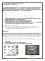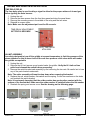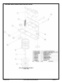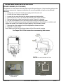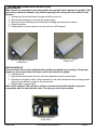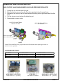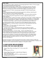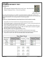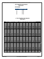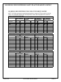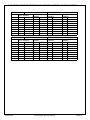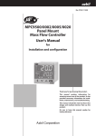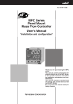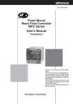
1
SERVICE MANUAL
SERIAL NUMBERS 2611 AND UP
NATURAL GAS AND PROPANE
SP8016-1005
ACCU-STEAM SERVICE MANUAL
Technical Services
Toll Free
Office
Fax
email
Web Site
SP8016-1005
800.480.0415
260.469.3040
260.493.8914
[email protected]
www.accutemp.net
ACCU-STEAM SERVICE MANUAL
TABLE OF CONTENTS
Table of contents
1
Document history
2
INTRODUCTION
3
SEQUENCE OF OPERATIONS
3
TROUBLESHOOTING MATRIX
4-5
REMOVAL AND INSTALLATION - TRANSFORMER
5
REMOVAL AND INSTALLATION - LAMPS
6
REMOVAL AND INSTALLATION - SWITCH
6
REMOVAL AND INSTALLATION - THERMOSTAT
7-8
REMOVAL AND INSTALLATION - TEMPERATURE SENSOR
8
REMOVAL AND INSTALLATION - TIME DELAY RELAY
9
REMOVAL AND INSTALLATION - HI LIMIT ASSEMBLY
9-10
REMOVAL AND INSTALLATION - STANDBY BURNER ( PILOT)
11
REMOVAL AND INSTALLATION - MAIN BURNERS
12
REMOVAL AND INSTALLATION - IGNITION MODULE
12
REMOVAL AND INSTALLATION - CONTROL AND MAIN VALVE AND PILOT REGULATOR 13
TESTING - FLAME SENSE
18-19
TESTING - CHAMBER INTEGRITY
19
CHART - RESISTANCE RTD TEMPERATURE SENSOR
20
CHART - RESISTANCE K TYPE TEMPERATURE SENSOR
20
CHART - ORIFICE SIZE VERSUS ELEVATION AND BTU CONTENT
21
Schematic - standard ignition
22
Schematic - intermittent ignition with main burner valve
23
Schematic - intermittent ignition
24
SP8016-1005
ACCU-STEAM SERVICE MANUAL
PAGE 1
Document history
Current
revision
1005
SP8016-1005
Date
5/14/10
Prior
revision Date
N/A
N/A
Change
Initial release of manual
ACCU-STEAM SERVICE MANUAL
PAGE 2
INTRODUCTION
The griddle is constructed and uses technology like no other griddle in the world. The griddle
cooking surface is the top of a chamber which has a unique environment. Welded stainless steel
reinforcements studs connect the chamber top to a chamber bottom. The perimeter joints are all
robotically welded and produce a vessel that is air tight. The chamber is filled half full with distilled
water. The remaining air is removed and the chamber is welded shut. At this point, the chamber
becomes a hermetically sealed vessel, never to be opened again. The griddle steam chamber
requires no water or maintenance. A thermo-well for a thermocouple and a thermo-well for the overtemp safety shutdown system are also welded into the griddle steam chamber. At temperatures below
212°F (100 C), the chamber is actually in a vacuum, similar to that of a canning jar. At temperatures
above 212 °F, the chamber operates under pressure. Located between the water and the bottom of
the cooking surface is the best heat transfer medium – steam, the most effective way to transfer heat.
The thermocouple senses the temperature of the steam and reports this data to the thermostat, which
energizes the burners. This system maintains the griddle cooking surface temperatures to within ±
3 °F over the entire cooking surface and provides a near instant temperature recovery, even on the
same spot on the griddle, when turning food in place.
Intermittent Ignition
SEQUENCE OF OPERATION S/N’s 7184 and UP
Power comes in the back of the unit and goes to the transformer. The transformer lowers the
voltage to 24 volts VAC. Power is then transferred to the high limit. When the circuit is energized
there will always be power to the thermostat. When the thermostat calls for heat it will send power
to the ignition module. Once the standby burner is lit and the module is satisfied power will then be
transferred to the time delay relay. When the time delay relay times down, the main burners will ignite.
When the heat cycle is over all burners will be off.
Continuous Pilot Burner
SEQUENCE OF OPERATION S/N 2611 to 7183
120V power is supplied to the primary side of the transformer. 24VAC comes off the secondary side
of the transformer which provides power to the over-temp / solder washer assembly. Once the ON/
OFF switch is set to the ON position, power is applied to the ignition module through the blue wire
and back out the red wire to the main gas control valve. The ignition module will send high voltage
to the Ignitor probes thus causing a spark to ignite the standby burner. If the ignition module doesn’t
sense a flame it drops power to the main gas control valve and will shut down the griddle. If the
ignition module receives the acceptable level of flame sense the ignition cycle continues and the time
delay relay times out and sends voltage to power to thermostat. The thermostat in conjunction with
the temperature sensor regulate the heat as required. If at any time the ignition module flame sense
voltage is not acceptable it cuts power to the griddle.
SP8016-1005
ACCU-STEAM SERVICE MANUAL
PAGE 3
TROUBLE SHOOTING MATRIX
SYMPTOM
Unit is cutting out and / or
shutting down
POSSIBLE CAUSE
Ignition probe
EVALUATION
Check for oxidation. Clean probes if oxidized. Check for
probes being loose in the ceramic. Make sure the ground
probe is touching the ceramic part of the heating element
and the other two probes should be the height of a nickel
off the ceramic. Millivolt readings, using the recommended
probe set, between the orange ignition wire and the green
ground wire should read between 30 to 50 DC millivolts
(.045 uA or higher) when the stand by burner is ignited.
This can be measured at the ignition module. Replace if
necessary.
Flue
Check for grease or food build up in the flue. Clean for
proper air flow. Check that the flue has not been pushed in.
Straighten if necessary.
Check for a cracked or sunken ceramic. Replace if
necessary.
Check for a plugged orifice. Clean as necessary.
Stand by (Pilot) burner
Orifice
Ignition module
Gas pressure.
Venturi tubes
Ventilation
Valves
Unit will not start
Hi-Limit over-temp
Switches
On and off contacts
Gas supply
Electric supply
Transformer
Ignition Cable
Orifices
Fuses
SP8016-1005
Check for loose connections or misaligned pins in the
Molex connector. Tighten or replace as necessary. Also
check the ignitor cable.
Main burners should be set at 5 and the stand by burner
should be set at 3.5 inches of water column for natural gas
when the griddle is in operation. For propane units the pilot
should be set at 8 inches and the main burner should be
set at 10 inches. Check to see if an external gas regulator
is affecting the pressures. Gas pressures to be checked
with the burners on.
Check for any blockage and clean as necessary.
Check for down drafts that might be blowing the pilot flame
out.
Check for loose connections or if they are sticking closed.
Replace as necessary.
Check to see if the solder washer is melted. Replace as
necessary. See over-temping section.
Check for continuity. Replace as necessary.
Check for continuity. Replace as necessary.
Check for gas supply to the unit and that the gas valve is
open.
Check that power is supplied to the unit. Check the ground
fault receptacle if used.
Check for line voltage to the primary side and that 24 volts
is present at the secondary side. Replace as necessary.
Check for cracks or loose connections.
Check for any blockage and clean as necessary.
Check for continuity. Replace as necessary.
ACCU-STEAM SERVICE MANUAL
PAGE 4
TROUBLE SHOOTING MATRIX
SYMPTOM
Unit is over / under temp
POSSIBLE CAUSE
Thermostat
Thermocouple
EVALUATION
This is a type K thermostat. Check that 24 volts AC is
present at terminals 4 & 5. For units with serial numbers
7551 and up, the thermostat will be a RTD type.
This is a type K thermocouple (red and yellow leads). Refer
to the thermocouple chart for proper measurements. For
units with serial numbers 7551 and up, this will be a RTD
probe. (two red leads) Must use the correct probe with the
type of thermostat installed.
Make sure that the unit is level. Perform the 9 point
temperature test and correspond with the temperature
setting. (three reading across the back, three across the
middle and three across the front. All readings should
be within 3 degrees. Check for hot spots or leaks. Notify
Accutemp Service with any fluctuating readings.
Uneven temperatures
Unit installation
Unit is blowing flames out of
the back
Flue
Clean the flue of any obstructions or build up.
Burners
Check for damaged ceramics. Replace as necessary
Gas pressure.
Maximum supply gas pressure should not exceed 0.5 psig.
(14” WC) External regulators should not be used unless
this reading is exceeded.
REMOVAL AND INSTALLATION
TRANSFORMER
1. Unplug the unit
2. Remove the three screws from the front door panel and drop the panel down.
3. Disconnect the wires from the primary and secondary side of the thermostat. Note their
locations.
4. Remove the nylock nuts and pull the transformer out.
5. Reassemble in reverse order.
Transformer
at0e-1809-1
SP8016-1005
ACCU-STEAM SERVICE MANUAL
PAGE 5
REMOVAL AND INSTALLATION
LAMPS
The lamps are a neon style lamp that is driven by 24vac.
1. Unplug the unit.
2. Remove the three screws from the front door panel and drop the panel down.
3. Remove the wires from the lamps.
4. Depress the locking ears on the lamp with a pair of pliers and push thru the front of the panel
5. Reinstall in reverse order.
POWER
at0e-1800-2
HEAT
at0e-1800-1
ON / OFF SWITCH AND CONTACTS
This switch consists of 4 parts and each can be changed individually if any of the parts
failed.
1. Unplug the unit.
2. Remove the three screws from the front door panel and drop the panel down.
3. Remove the wires from the contacts and note their location.
4. Push the spring loaded locking tab on the mounting ring and pull the switch out from the front
of the panel.
5. Pry the contacts off of the locking ring.
6. Reinstall in reverse order.
Switch, selector
AT0E-3336-1
SP8016-1005
Mounting block
AT0E-3339-1
ACCU-STEAM SERVICE MANUAL
CONTACT, ON
AT0E-3338-1
2 REQUIRED
PAGE 6
REMOVAL AND INSTALLATION
THERMOSTAT
WARNING - ALL THERMOSTATS MUST BE CALIBRATED TO 400 °F, ( +1 °F,/-4 °F,)
1. Unplug the unit
2. Remove the three screws from the front door panel and drop the panel down.
3. Remove the knob and retaining nut from the front of the panel.
4. Disconnect the wires from the pins on the thermostat. Note their locations.
5. Reassemble in reverse order.
Note: Units with serial numbers 2611 to 7550 have a type K thermostat and thermocouple.
(red and yellow leads) Serial numbers 7551 and above have a RTD thermostat and probe.
(two red leads). When replacing a thermostat, always use a RTD thermostat and probe.
K Type Temperature Controller - P/N AT0E-2559-3
This was replaced by the RTD
Controller P/N AT0E-2559-6 &
Thermocouple P/N AT0E-2885-3
Must be used on all older series
griddles with the welded in
thermocouple
Calibration Pot
RTD Type Temperature Controller - P/N AT0E-2559-6
Must use RTD Thermocouple
P/N AT0E-2885-3
Calibration Pot
SP8016-1005
ACCU-STEAM SERVICE MANUAL
PAGE 7
REMOVAL AND INSTALLATION
RTD THERMOSTAT CALIBRATION
The operating temperature range is 200 °F to 400 degrees F. Record the measured griddle surface
temperature at the set points of 200 °F, 300 °F and 400 °F to determine if the controller is out of
range. The calibration offset potentiometer shifts the range up or down but range or gain width is fixed
and cannot be adjusted. If the controller is ± 10 °F out of range, replace it.
1. Open the control panel
2. Plug the unit in and hook up the gas supply.
3. Place a weighted temperature probe on the cooking surface of the griddle in a location above
the griddle temperature sensor. Keep the probe off of the dimples and use a small amount of
high temperature cooking oil between the surface of the probe and giddle.
4. Set the thermostat at 200 °F, turn the unit on and allow the temperature to stabilize. Take a
reading from the thermometer and record the value.
5. Set the thermostat at 300 °F, allow to stabilize and record the value.
6. Set the thermostat at 400 °F, allow to stabilize and record the value.
7. Take a reading from the thermometer. The value should be 400 °F (+1 °F / -4 °F).If not, adjust
the offset potentiometer on the thermostat and allow the unit to stabilize.
8. Repeat step 7 as is necessary.
9. Close the control panel, install the retaining screws and allow the unit to stabilize.
10. Observe the thermometer. The indicator reading should be 400 degrees F (+1 °F / -4 °F). If
the reading is not, open the panel and repeat steps 7 – 9.
TEMP PROBE
The temperature sensor is screwed into a thermal-well underneath the griddle chamber. It is
isolated from the distilled water of the griddle chamber. It is designed to indicate temperature
by changing the resistance based on temperature to the thermostat. Be careful if you have to
drill out the sensor not to puncture the chamber as it will render the griddle un-repairable.
1. Unplug the unit.
2. Remove the three screws from the front door panel and drop the panel down.
3. On the bottom side of the unit, locate the thermal-well that the probe capillary is screwed into
and remove.
4. Remove the leads from pins 6 & 7 on the thermostat.
5. Reinstall in reverse order. (Type K probe, yellow on #6 and red on #7)
Probe location
underside of griddle
SP8016-1005
rtd Temperature sensor
AT0e-2885-3
ACCU-STEAM SERVICE MANUAL
PAGE 8
REMOVAL AND INSTALLATION
TIME DELAY RELAY
The time delay relay is used to delay a signal to allow for the proper mixture of air and gas
before igniting the main burners.
1. Unplug the unit
2. Remove the three screws from the front door panel and drop the panel down.
3. Remove the mounting screw in the middle of the relay and the two wires.
4. Reinstall in reverse order.
Note: Make sure the adjustment pot is set for 20 seconds.
Time delay adjustment
set for 20 seconds
Relay, time delay
at2h-2500
HI-LIMIT ASSEMBLY
Is a safety designed to turn off the griddle at a preset temperature to limit the pressure of the
steam chamber so that it doesn’t set off the one time pressure relief valve which will render
the griddle un-repairable
1. Unplug the unit.
2. Remove the Hi-Limit access cover located under the griddle. Verify the Hi Limit rod has
pulled and released the switch before proceeding.
3. Remove the switch bracket and assembly by first removing the two nuts. Be careful not to lose
any of the parts located underneath.
Note: The entire assembly will want to drop down when removing the bracket.
4. Replace the rod, solder washer, flat washer and the spring. Put the two washers on the studs
and reattach the switch bracket
Note: It is extremely important that the solder washer has good surface contact with the
surface of the thermal-well. Make sure the solder washer is installed before the flat washer.
5. Reattach the spring and access cover. See the drawing on the following page.
Solder washer
At2m-2860-1
Washer
at2f-1367-1
Rod
at2m-2861-1
Microswitch
at2e-1639-1
SP8016-1005
Extension
spring
at2h-1640-1
Compression
Spring
at2h-1365-1
Bracket, switch
at2m-1558
Microswitch
cover
at2e-1759
ACCU-STEAM SERVICE MANUAL
PAGE 9
REMOVAL AND INSTALLATION
SP8016-1005
ACCU-STEAM SERVICE MANUAL
PAGE 10
REMOVAL AND INSTALLATION
STANDBY BURNER (PILOT BURNER)
This device is a small ceramic burned used to ignite the main burners. It also has the ignition probe
and flame sense probe. Improper installation can cause the griddle not ignite or intermittently
shutdown
1. Unplug the unit and shut off the gas supply and let the unit cool.
2. Loosen the hose clamp on the venturi.
3. Loosen the two nuts that hold the burner spacer and step bracket.
4. Remove the two nuts on the studs that hold the ignitor sensor bracket.
5. Remove the ignitor cable from the ignitor probe. Inspect for damage.
6. Pull the orifice adaptor out of the venturi and pull the pilot assembly down.
Note: Check the ignitor probes and ground plane assembly for discoloration or oxidation and
replace as needed. Also check for proper gapping. See illustration below.
7. Remove the orifice adaptor from the compression elbow and clean.
8. Reinstall in reverse order.
Note: Make sure that the hose clamp does not block the venturi opening.
See Pages XX to XX for instructions on measuring flame sense.
PROBES
IGNITOR & FLAMES SENSE SETTING
STANDBY BURNER
AT2A-2255-2
SP8016-1005
Ignitor kit
ACCU-STEAM SERVICE MANUAL
PAGE 11
REMOVAL
MAIN
BURNERS AND INSTALLATION
Main burners are a ceramic burner that supplies the required heat to operate the griddle. If the
get wet they should be allowed to dry without applying heat as they will crack and will need
replaced
1. Unplug the unit and disconnect the gas and let the unit cool.
2. Remove the retaining nut from the gas supply elbow.
3. Remove the four retaining nuts from burner box flange and drop the box down.
4. Clean the orifices.
5. Reassemble in reverse order and run the unit up to 400 degrees.
Burner 24” Model
at2b-2131-1
36”& 48” Model Burner
at2b-2991-1
IGNITION MODULE
Is the electronic device that verifies that the griddle has ignited and is running. If the proper
signals are not received from the flame sense it will lockout the griddle.
1. Unplug the unit.
2. Remove the three screws from the front door panel and drop the panel down.
3. Disconnect the ignition cable, molex connector for the wire harness and the mounting screws.
Apply silicone dielectric grease to the connections.
4. Reassemble in reverse order.
Note: Serial numbers 7184 and above will have an Interim Intermittent Ignition system in
conjunction with the dual solenoid valve. The main gas valve was removed
Ignition module
at2e-1807-1
SP8016-1005
ACCU-STEAM SERVICE MANUAL
PAGE 12
REMOVAL AND INSTALLATION
GAS CONTROL VALVE, MAIN BURNER VALVE AND PRESSURE REGULATOR
1. Unplug the unit and disconnect the gas.
2. Remove the three screws from the front door panel and drop the panel down.
3. Disconnect the union on the left hand side and the fitting on the right hand side of the flex
hose.
4. Pull the valves out and replace the defective part.
5. Reassemble in reverse order.
OLD STYLE VALVE TRAIN
S/N 2661 TO 7894
NEW STYLE VALVE TRAIN
S/N 7895 & UP
Pressure Adjustment
Remove Dust Cap to adjust
1/4 NPT
1/8 NPT
Control Valve and Pilot Valve gas pressures must be adjusted after replacing to assure to
assist in correct operation.
GAS PRESSURE CHART
GAS TYPE
NATURAL
PROPANE
MAIN PRESSURE
5 INCHES WATER COLUMN
10 INCHES WATER COLUMN
Control Valve
AT2E-1806-2 - NG (5”wc)
AT2E-1806-3 - P (10”wc)
SP8016-1005
PILOT PRESSURE
3.5 INCHES WATER COLUMN
8 INCHES WATER COLUMN
Main Burner Valve
at2e-2087-1
S/N 7894 & Lower
ACCU-STEAM SERVICE MANUAL
Pilot Valve
At0p-2847-1- NG (3.5”WC)
AT0P-2847-2 - P (8” WC)
PAGE 13
TESTING
Flame Sense Measurement
The ACCU-STEAM gas griddle has a flame sensing circuit to determine if the system has proper
combustion. When the system is turned on gas is sent to the pilot burner and an electronic
ignition tries to ignite the griddle. The griddle then checks to see if flame is established in the
pilot burner. If the flame sense feedback voltage is within the proper range the system will ignite
the main burners and they stay on until the thermostat is satisfied. The griddle flame sense
continues to monitor the voltage and as long as it within the proper range the griddle will stay on.
If the flame sense voltage falls below the threshold the griddle will go into lock out and will shut
down the griddle. Cycling the on/off switch will restart the ignition and flame sense test. If it fails
again you may need to troubleshoot the ignition/flame sense section.
TROUBLESHOOTING
How to make a diagnosis:
1. Determine that power is present at the griddle
2. Determine that gas is supplied at the proper pressures to the unit.
3. Install an inch-units H2O manometer onto the port on the side of the main gas regulator valve
and onto the pressure tap outboard of the pilot regulator.
4. Install a flame-sensing probe into the flame sense circuit.
a. A meter with micro amp (<A) selection or a micro amp adapter must be place in series
with the orange flame sense wire. To check micro amps, disconnect the orange wire
from the flame rod, connect the amp meter in series with the flame sensing rod
terminal and the orange wire from the wiring harness.
b. An Accutemp volt-measuring adapter P/N FT0003 (meter set for millivolts) is placed in parallel
with the orange flame sense circuit. Attach one end of the adapter to the orange wire and the
other to ground.
5. Turn the unit on (Power lamp is lit)
6. If the pilot burner is not lighting and there is no spark, check for 24 VAC input to the ignition
module.
a. If there is 24VAC present at the ignition module and all of the ground connections are
good, check the ignition cable for an open or a short to ground.
b. If there is 24VAC present at the ignition module and all of the ground connections and
the ignition cable are good, test for spark by disabling the main regulator gas valve and
place the ignitor cable close to ground. Turn the griddle ON. If there is no spark,
replace the ignition module.
c. If there is a spark, check the ignitor probe spark gap on the pilot burner. Adjust, if
necessary. If the probes look badly oxidized, replace the probes.
7. If there is spark but no gas to the pilot regulator, check for 24VAC at the gas valve coil. If
24VAC is not present at the coil of the main regulator gas valve, and the connecting harnesses
are good, replace the ignition module.
8. If 24VAC is present at the gas valve coil and no gas is flowing to the pilot regulator, replace
the main regulator gas valve. When changing the valve, check for debris in the gas line and
valve. Ensure that a drip leg is installed before the unit.
regulator.
SP8016-1005
ACCU-STEAM SERVICE MANUAL
PAGE 14
TESTing
9. If the pilot burner is lighting, determine if the sensing signal level is 25mV (1.07uA) or higher
(see the attached millivolt to micro amp chart).
a. If the level is less than 25mV (1.07uA), check for proper gas pressures to the main
regulator and to the pilot regulator. For natural gas, the pressures must be 5" H2O for
the main gas valve and 3.5" H2O for the pilot burner regulator. For propane gas, the
pressures must be 10" H2O for the main gas valve and 8.0" H2O for the pilot burner
regulator.
b. If the gas pressures are good but the sensing signal level is still poor, check the pilot
orifice for obstruction. Clean or replace as necessary.
c. If the gas pressures are good, the pilot orifice is clean, the burner surface is glowing
orange to bright orange but the signal level is still poor, replace the ignitor probe set
and ground plane.
10. Four types of meter readings are possible: 0 millivolts or 0 micro amps; a steady reading of 25
millivolts or 1.07 micro amps or more; a low reading less than 25 millivolts or 1.07 microamps;
or a fluctuating reading that won’t stabilize. The possible causes for each type of reading are:
a. 0 millivolts or micro amps – Look for an open or grounded sensor wire or flame rod,
or a defective ignition module. The wire and rod can be diagnosed with an ohmmeter.
Make the diagnosis of a defective ignition module after all other possibilities have been
exhausted.
b. 25 millivolts or 1.07 micro amps, with a steady reading – The system is
operating within normal parameters.
c. Fluctuating meter reading – Check that the flame sensor probes are properly
located. Also check for drafts that can cause an unstable flame. A dirty orifice can also
cause an unstable flame.
d. Less than 25 millivolts or 1.07 micro amps – Look for a pilot flame that’s not
properly engulfing the flame-sensing rod. A flame sensor probe too close to the tile will
not be in the proper part of the flame, with not enough ionized gas to allow a proper
signal level to be conducted. Conversely, the same thing holds true if the flame sensor
is too high. Also check the ground connection back to the ignition module. Check that
the flame-sensing rod and ground plane are not oxidized. Clean both with a non
aluminum oxide abrasive.
Important! The ignition module should be the last item that is replaced. Ignition modules are
designed and tested to rigorous standards to ensure safe and consistent operation. Therefore, focus
on other less robust components before swapping out the ignition module.
Flame Sense Measurement
Using the voltage method
1. Connect Flame Tester, AccuTemp P/N FT- 003 to your multimeter
2. Set multi-meter to DC mv.
3. Connect Flame Tester leads, to Igniter Harness Orange (or
Yellow) and Green wires.
4. Verify your reading is above 60 DC mv and the system will
shutdown below 19 DC mv.
SP8016-1005
ACCU-STEAM SERVICE MANUAL
PAGE 15
TESTing
CHAMBER INTEGRITY TEST
Tools Required:
• Level
• Calibrated Digital Temperature Meter (Such as the Cooper - Atkins EconoTemp
• Weighted Temperature Probe - ( Such as Cooper/Atkins)
DIgital Temperature Meter
&
Weighted Temperature Probe
Due to the patented design of our griddle it is imperative that the chamber has no leaks as this
allows water to escape and air to move in causing inconsistent temperatures on the cooking surface.
This test will determine if the cooking chamber is functioning properly.
Notes:
Do not use a infrared temperature measuring device as it will not work correctly.
1. Verify griddle is level front to back and side to side before attempting this procedure.
2. With the griddle plugged in, set thermostat dial to 200ºF and turn on. If this is a internal thermostat model
you will need to open the control panel to set the thermostat.
3. Place the weighted temperature probe in the center in the first 1/3 of the griddle cooking surface on a
4.
5.
6.
7.
small amount of high temperature cooking oil. Make sure that the probe is between the griddle
weld stud dimples to assure a proper reading.
Allow the griddle to heat to the initial temperature setting.
Increase thermostat setting to 300ºF allow griddle to cycle through two heat cycles.
Place weighted temperature probe and record temperatures according to the chart below
Temperatures shall be within ±5º F of each other across the entire surface.
SP8016-1005
ACCU-STEAM SERVICE MANUAL
PAGE 16
Temperature sensor (thermocouple) resistance chart
RTD TEMPERATURE SENSOR
AT0E-2885-3
RTD PROBE
°F
0
100
200
300
400
RTD Resistance Value
1000Ω
1146Ω
1359Ω
1569Ω
1775Ω
K TYPE TEMPERATURE SENSOR
AT0E-2885-2
TYPE K THERMOCOUPLE READINGS - THERMOELECTRIC VOLTAGE IN DC MILLIVOLTS
F°
70
80
90
100
110
120
130
140
150
160
170
180
190
200
210
220
230
240
250
260
270
280
290
300
310
320
330
340
350
SP8016-1005
0
0.843
1.068
1.294
1.521
1.749
1.977
2.207
2.436
2.667
2.897
3.128
3.359
3.59
3.82
4.05
4.28
4.509
4.738
4.965
5.192
5.419
5.644
5.869
6.094
6.317
6.54
6.763
6.985
7.207
1
0.865
1.09
1.316
1.543
1.771
2
2.23
2.459
2.69
2.92
3.151
3.382
3.613
3.843
4.073
4.303
4.532
4.76
4.988
5.215
5.441
5.667
5.892
6.116
6.339
6.562
6.785
7.007
7.229
2
0.888
1.113
1.339
1.566
1.794
2.023
2.253
2.483
2.713
2.944
3.174
3.405
3.636
3.866
4.096
4.326
4.555
4.783
5.011
5.238
5.464
5.69
5.914
6.138
6.362
6.585
6.807
7.029
7.251
3
0.91
1.136
1.362
1.589
1.817
2.046
2.276
2.506
2.736
2.967
3.197
3.428
3.659
3.889
4.119
4.349
4.578
4.806
5.034
5.26
5.487
5.712
5.937
6.161
6.384
6.607
6.829
7.052
7.276
4
0.933
1.158
1.384
1.612
1.84
2.069
2.298
2.529
2.759
2.99
3.22
3.451
3.682
3.912
4.142
4.372
4.601
4.829
5.056
5.283
5.509
5.735
5.959
6.183
6.406
6.629
6.852
7.074
7.296
5
0.955
1.181
1.407
1.635
1.863
2.092
2.321
2.552
2.782
3.013
3.244
3.474
3.705
3.935
4.165
4.395
4.623
4.852
5.079
5.306
5.532
5.757
5.982
6.205
6.429
6.652
6.874
7096
7.318
6
0.978
1.203
1.43
1.657
1.886
2.115
2.344
2.575
2.805
3.036
3.267
3.497
3.728
3.958
4.188
4.417
4.646
4.874
5.102
5.328
5.554
5.779
6.004
6.228
6.451
6.674
6.896
7.118
7.34
ACCU-STEAM SERVICE MANUAL
7
1
1.226
1.453
1.68
1.909
2.138
2.367
2.598
2.828
3.059
3.29
3.52
3.751
3.981
4.211
4.44
4.669
4.897
5.124
5.351
5.577
5.802
6.026
6.25
6.473
6.696
6.918
7.14
7.362
8
1.023
1.249
1.475
1.703
1.931
2.161
2.39
2.621
2.851
3.082
3.313
3.544
3.774
4.004
4.234
4.463
4.692
4.92
5.147
5.374
5.599
5.824
6.049
6.272
6.496
6.718
6.941
7.163
7.384
9
1.045
1.271
1.498
1.726
1.954
2.184
2.413
2.644
2.874
3.105
3.336
3.567
3.797
4.027
4.257
4.486
4.715
4.943
5.17
5.396
5.622
5.847
6.071
6.295
6.518
6.741
6.963
7.185
7.407
10
1.068
1.294
1.521
1.749
1.977
2.207
2.436
2.667
2.897
3.128
3.359
3.59
3.82
4.05
4.28
4.509
4.738
4.965
5.192
5.419
5.644
5.869
6.094
6.317
6.54
6.763
6.985
7.207
7.429
PAGE 17
GAS GRIDDLE ORIFICE Reference CHART FOR altitude and btu content
GAS GRIDDLE ORIFICE REFERENCE TABLE FOR ALTITUDE AND BTU CONTENT
NOTE: This Table represents the standard upper and lower ranges of BTU per cubic foot content.
There is no relationship between the natural gas BTU content and the propane BTU content as
shown in each section of this Table.
HEAT VALUE BTU/CU FT. (NATURAL GAS - 990, PROPANE GAS - 2200)
24" GRIDDLE MAIN 36" GRIDDLE
48" GRIDDLE
PILOT BURNER
BURNER
MAIN BURNER
MAIN BURNER
Altitude ft
NG
LP
NG
LP
NG LP
NG LP
3000
#59
#71
#49
#56
#40 #54
#40 #53
4000
#59
#71
#50
#57
#43 #53
#44 #53
5000
#59
#72
#50
#57
#44 #54
#45 #54
6000
#60
#73
#51
#58
#44 #54
#46 #54
7000
#61
#73
#51
#58
#45 #54
#47 #54
8000
#61
#74
#52
#58
#46 #54
#47 #55
9000
#62
#74
#53
#58
#47 #56
#49 #56
10000
#64
#74
#53
#59
#48 #56
#50 #56
HEAT VALUE
Altitude ft
3000
4000
5000
6000
7000
8000
9000
10000
HEAT VALUE
Altitude ft
3000
4000
5000
6000
7000
8000
9000
10000
SP8016-1005
NATURAL GAS - 1000
24" GRIDDLE MAIN
PILOT BURNER
BURNER
NG
LP
NG
LP
#59
#71
#49
#57
#59
#71
#50
#58
#60
#72
#51
#58
#61
#73
#52
#58
#62
#73
#53
#58
#63
#74
#54
#59
#64
#74
#55
#59
#65
#74
1.25MM
#60
PROPANE GAS - 2300
36" GRIDDLE MAIN 48" GRIDDLE MAIN
BURNER
BURNER
NG LP
NG LP
#42 #54
#43 #55
#42 #54
#43 #55
#45 #54
#44 #56
#45 #55
#44 #56
#46 #55
#45 #56
#46 #55
#45 #56
#47 #55
#47 #57
#48 1.25MM
#48 #58
NATURAL GAS - 1100
24" GRIDDLE MAIN
PILOT BURNER
BURNER
NG
LP
NG
LP
#59
#71
#50
3/64
#60
#71
#51
#57
#61
#72
#52
#57
#62
#73
#52
#57
#63
#73
#53
#57
#64
#74
#54
#58
#65
#74
#54
#59
#65
#74
#54
#59
PROPANE GAS - 2400
36" GRIDDLE MAIN 48" GRIDDLE MAIN
BURNER
BURNER
NG LP
NG LP
#43 #54
#42 #55
#43 #54
#44 #55
#44 #55
#45 #55
#44 #55
#45 #55
#46 #55
#46 1.25MM
#47 #55
#47 1.25MM
#48 1.25MM
#48
3/64
#49 1.25MM
#49
3/64
ACCU-STEAM SERVICE MANUAL
PAGE 18
GAS GRIDDLE ORIFICE Reference CHART FOR altitude and btu content
HEAT VALUE
NATURAL GAS - 1200
24" GRIDDLE MAIN
PILOT BURNER
BURNER
Altitude ft NG
LP
NG
LP
3000
#60
#71
#51
3/64
4000
#61
#71
#51
#57
5000
#63
#72
#52
#57
6000
#63
#72
#52
#57
7000
#64
#72
#53
#57
8000
#65
#72
#54
#58
9000
#65
#72
#54
#59
10000
#66
#72
#54
#59
PROPANE GAS - 2500
36" GRIDDLE MAIN 48" GRIDDLE MAIN
BURNER
BURNER
NG
LP
NG
LP
#43
#54
#42
#55
#43
#54
#44
#55
#44
#55
#45
#55
#44
#55
#45
#55
#46
#55
#46
1.25MM
#47
#55
#47
1.25MM
#48
1.25MM
#48
3/64
#49
1.25MM
#49
3/64
HEAT VALUE
PROPANE GAS - 2700
36" GRIDDLE MAIN 48" GRIDDLE MAIN
BURNER
BURNER
NG
LP
NG
LP
#46
#53
#45
#54
#46
#54
#47
#54
#47
#54
#48
#55
#48
#54
#48
#55
#49
#55
#49
#56
#50
#55
#50
#56
#51
1.25MM
#50
#56
#52
1.25MM
#51
#57
NATURAL GAS - 1300
24" GRIDDLE MAIN
PILOT BURNER
BURNER
Altitude ft NG
LP
NG
LP
3000
#60
#71
#52
#56
4000
#62
#72
#52
#56
5000
#63
#73
#53
#56
6000
#64
#73
#54
#58
7000
#64
#74
#55
#58
8000
#65
#74
#55
#59
9000
#66
#74
#55
#60
10000
#68
#75
#56
#62
SP8016-1005
ACCU-STEAM SERVICE MANUAL
PAGE 19
SCHEMATICS
AT2T-3041-1
STANDARD IGNITION
SERIAL NUMBERS 2661 TO 7184
BLK
24V
SEC
BLK
120V
PRI.
WHT
BLU
YEL
WHT
N.C.
OFF
N.O .
RED
SW2
O. T. SW
1
P1
2
1
J1
2
VIO
RED
MAIN GAS
CONTROL
VALVE
RED
VIO
1
2
PWR NA
3
K TYPE CONTROLLER
COM
4
6
+
VIO
RED
DELAY
TIMER
RED
WHT
PWR
LT1
RED
MAIN
BURNER
VALVE
ORN
YEL
K TYPE
7
-
2
5
OUTPUT
BLU
to
CAL OFFSET ADJ
1
BLU
RED
BLK
RED
ON
GRN
ORN or YEL
GRN
3
4
5
RED
HEAT
LT2
SENSOR
6
BURNER
SPARK
MODULE
HV IGNITOR
AT2T-3041-1
AT2T-3041
SP8016-1005
ACCU-STEAM SERVICE MANUAL
PAGE 20
SCHEMATICS
AT2T-3041-3
INTERMITTENT IGNITION WITH MAIN BURNER VALVE
SERIAL NUMBERS 7185 TO 7894
BLK
BLK
120V
PRI.
24V
SEC
WHT
BLU
YEL
WHT
N.C.
OFF
N. O.
RED
P1
2
1
J1
2
YEL
VIO
RED
SW2
O.T. SW
1
ON
RED
BLK
MAIN GAS
CONTROL
VALVE
VIO
1
PRTD TYPE CONTROLLER
RED
L1
YEL
PWR
LT1
3
L2
5
6
OUTPUT
to
8
CAL OFFSET ADJ
9
BLU
1
2
3
5
MAIN
BURNER
VALVE
ORN
DELAY
TIMER
RED
RED
ORN or YEL
GRN
4
YEL
PRTD
PRTD
GRN
RED
WHT
HEAT
LT 2
SENSOR
6
BURNER
SPARK
MODULE
HV IGNITOR
AT2T-3041 -3
SP8016-1005
ACCU-STEAM SERVICE MANUAL
PAGE 21
SCHEMATICS
AT2T-3041-2
INTERMITTENT IGNITION
SERIAL NUMBERS 7895 & UP
BLK
BLK
120V
PRI.
24V
SEC
WHT
BLU
YEL
WHT
N. C.
OFF
N.O.
RED
P1
2
1
J1
2
VIO
MAIN GAS
CONTROL
VALVE
RED
SW2
O.T. SW
1
ON
RED
MAIN
BURNER
VALVE
RED
BLK
VIO
ORN
RED
DELAY
TIMER
1
L1
PRTD TYPE CONTROLLER
YEL
HEAT
LT 2
3
L2
5
6
OUTPUT
o
t
1
2
3
4
5
PWR
LT 1
RED
RED
ORN or YEL
GRN
BLU
YEL
PRTD
8
9
- PRTD -
CAL OFFSET ADJ
GRN
RED
WHT
SENSOR
6
BURNER
SPARK
MODULE
HV IGNITOR
AT2T-3041 -2
SP8016-1005
ACCU-STEAM SERVICE MANUAL
PAGE 22
SP8016-1005
ACCU-STEAM SERVICE MANUAL