1
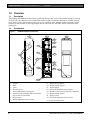
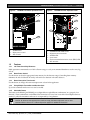
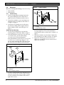
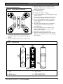
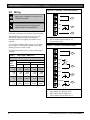
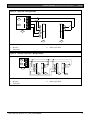
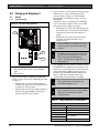
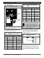
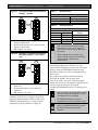
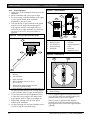
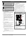
DS484Q/DS486Q
Installation Instructions
EN
Quad Beam
Photoelectric Detectors
DS484Q/DS486Q | Installation Instructions | 1.0
Overview
1.0 Overview
1.1
Description
The DS484Q and DS486Q are photoelectric quad beam detectors that use four pulsed infrared beams to activate
an alarm relay upon detection of an intruder. Both models contain a transmitter that emits an invisible infrared
beam, and a receiver. If the beam is broken, the receiver signals an alarm. Multiple channel operation provides
increased system flexibility by allowing multiple devices to be used near each other without cross-talk or other
interference.
1.2
Components
Figure 1:
DS484Q/DS486Q Components
1
2
3
10
11
5
6
4
12
13
7
14
15
8
16
17
9
123456-
Chassis
Base
Cover
Mounting holes
Vertical adjustment screw (upper)
Terminal block (transmitter has five terminals,
receiver has nine terminals)
7 - Wire entrance
8 - Vertical adjustment screw (lower)
2
9 - Base mounting screws
10 - Optical module (upper)
11 - Scope (upper)
12 - Horizontal adjustment screw (upper)
13 - Operation panel (refer to Figure 2 or Figure 3)
14 - Optical module (lower)
15 - Scope (lower)
16 - Horizontal adjustment screw (lower)
17 –Cover mounting screw
Bosch Security Systems, Inc. | 7/05 | 4998138530F
DS484Q/DS486Q | Installation Instructions | 1.0
Overview
.
Figure 2:
DS486Q Transmitter Operation Panel
Figure 3:
DS486Q Receiver Operation Panel
1
3
ALIGNMENT IS COMPLETED
WHEN ‘ ‘ IS OFF
POWER
ALARM
1
2
100
200
130
260
160
320
OUTDOOR 60
INDOOR 120
4
150 200
400
75
200
400
5
50
500
INTERRUPTION
TIME (msec)
2
BEAM POWER CONTROL (m)
SWITCH
OFF ↔ ON
No ITEM OFF ON
1 Group A B
2 SEE CHART
3 BELOW
4 NULL SW2 - 3 : CHANNEL
M 1
2
3
SW2 OFF OFF ON ON
SW3 OFF ON OFF ON
300
100
180
360
EDC LEVEL
SWITCH
OFF ↔ ON
No ITEM
OFF ON
1 Group
A B
2 SEE CHART
3 BELOW
4 AND/OR AND OR
5 BYPASS OFF ON
6 SOUND OFF ON
CHECK
SW2 - 3 : CHANNEL
3
6
M 1 2 3
SW2 OFF OFF ON ON
SW3 OFF ON OFF ON
MODEL:DS486Q
1 - POWER LED
2 - Beam power control
3 - DIP switches
1.3
Features
1.3.1
100 Times Sensitivity Allowance
ALIGNMENT
CHECK
TERMINALS
123456-
INTERRUPTION TIME switch
Alignment check terminals
ALARM LED
Level meter
Environmental discrimination circuit (EDC) LED
DIP switches
Stable operation is maintained even if 99% of beam energy is cut by environmental disturbances such as rain, fog,
or frost.
1.3.2
Beam Power Control
Use this feature to select the appropriate beam intensity for the detection range. Controlling beam intensity
minimizes the risk of reflection off nearby walls and cross detection with other detectors.
1.3.3
Beam Interruption Time Control
Use this feature to change the beam interruption time to best fit the application.
1.3.4
Using Multiple Transmitter-and-Receiver Sets
Up to four transmitter-and-receiver sets can be stacked.
1.3.5
Selectable Beams
The beams in the DS484Q and DS486Q are configurable into eight different combinations (two groups by four
channels). These combinations can eliminate false alarms that can occur from cross-talk when multiple beams are
stacked, or when the transmitter and receiver are separated by a long distance.
The diameter of the transmitted beam increases with increased distance between the transmitter and
receiver. At distances that approach the maximum range, the beam might reach two or more
receivers. Refer to Section 2.1.2 Beam Spread on page 5 for additional information.
Bosch Security Systems, Inc. | 7/05 | 4998138530F
3
DS484Q/DS486Q | Installation Instructions | 1.0
1.3.6
Selectable AND/OR Gate
The photoelectric intrusion detection system in the
DS484Q and DS486Q provides alarm relay activation
for different considerations. Use the DIP Switches to
select the required protection:
AND gate – All four beams must be blocked
simultaneously to cause an alarm. This setting results in
fewer false alarms caused by birds and other small
animals.
OR gate – Either the upper or lower pairs of beams
must be blocked. This setting can detect an intruder
crawling on the ground.
1.3.7
Environmental Discrimination Circuit (EDC)
The Environmental Discrimination Circuit (EDC)
sends a signal when maintaining stable operation
becomes difficult due to environmental disturbances.
The EDC detects the gradual loss of signal along the
beam’s path because of dirt built up on the cover, or
because of rain, fog, or snow. If the signal decreases by
95% over at least 4-seconds, the EDC activates the
EDC LED (refer to Figure 3 on page 3) and relay. This
indicates that something is partially blocking a beam,
or that the covers need cleaning.
Overview
Table 1:
EDC BYPASS Switch States
Detector Status
BYPASS Switch
OFF
BYPASS Switch
ON
Poor
Environmental
Condition*
EDC LED lights
and EDC signal
is provided
through the
normally-closed
relay output at
the receiver.
EDC LED turns
on and EDC
signal is provided
through the
normally-closed
relay output at
the receiver.
The alarm is
generated by loss
of beam energy.
With the loss of
beam energy, the
ALARM LED
lights but alarm
signal is not
generated (alarm
relay is
automatically
shunted).
EDC LED turns
on and EDC
signal is provided
EDC LED turns
on and EDC
signal is
provided.
No alarm output
is generated.
If another optical
module is
blocked, the
ALARM LED
turns ON, but no
alarm signal is
generated.
After the
specified
interruption time,
the ALARM LED
turns ON and
alarm signal is
generated.
After the
specified
interruption time,
the ALARM LED
turns ON, and
alarm signal is
generated.
If beams are
blocked for more
than 3 seconds,
EDC LED turns
ON, and EDC
signal is
generated.
EDC LED does
not turn ON, and
EDC signal is not
provided.
When either
optical module is
blocked for 3 or
more seconds.
The EDC feature was not evaluated by
Underwriters Laboratories (UL).
Figure 4:
Receiver DIP Switches
When both
optical modules
are blocked for 3
seconds.
1
2
1 - DIP switches 1through 4 and 6 in the OFF
position
2 - DIP Switch 5 (EDC BYPASS Switch) in the
ON position
To use the EDC Bypass Switch, set the receiver’s DIP
Switch 5 to ON or OFF (Figure 4). Refer to Table 1 for
information about the functions and detector status.
∗
Poor environmental condition refers to difficulty in maintaining
stable operation due to environmental disturbances like fog or
rain.
Connect the EDC to a trouble circuit.
Check the system after the EDC relay
activates.
4
Bosch Security Systems, Inc. | 7/05 | 4998138530F
DS484Q/DS486Q | Installation Instructions | 2.0
Installation
.
2.1.1
2.0 Installation
2.1
Installation Considerations
Read the following information before installing,
wiring, and performing regular maintenance on the
equipment.
Do not install the detector:
• near trees and plants where falling leaves can block
the beam
• where intense sources of light and sunlight can
reflect directly into the receiver optics
A beam of light shining at a ±3-degree
angle of each receiver can cause false
alarms.
The beam strength is best if used within the maximum
range of the detectors. If used for shorter distances,
excess beam energy reaches the receiver resulting in
reflection off nearby walls and incorrect
communication with other detectors.
2.1.2
Figure 5:
Beam Spread
The beam spread is +0.7°. Refer to Figure 5 and Table 2
to determine the installation conditions.
Table 2:
Beam Spread Distances
Between
Transmitter and
Receiver∗
m
•
•
•
•
on movable surfaces
where subject to splashing water or sea spray
beyond the maximum range of each model
where strong electrical noise or radio frequency
interference occurs
• where strong vibration occurs
• in the presence of corrosive or explosive gas
Face upper and lower optical modules toward each
other on the transmitter and the receiver.
• Do not install or wire detectors during a
thunderstorm.
• Do not supply power until all wiring is
completed.
• Maintain power between 10.5 VDC and
28 VDC at all times.
• Do not disassemble or modify the base.
Beam Strength over Distance
∗
Horizontal
Spread∗
Total Vertical
Spread∗
ft
m
ft
m
ft
20
66
0.5
1.7
0.8
2.6
40
131
1.0
3.3
1.3
4.3
60
197
1.5
4.9
1.8
5.9
80
263
2.0
6.6
2.2
7.2
100
328
2.5
8.2
2.7
8.9
120
394
3.0
9.8
3.2
10.5
140
459
3.5
11.5
3.7
12.1
160
525
4.0
13
4.2
13.7
180
591
4.5
14.8
4.7
15.4
200
656
6.0
16.4
5.2
17.1
Refer to Figure 5.
Beam Spread
1
4
2
1 - Beam spread
2 - Distance between transmitter and receiver
Bosch Security Systems, Inc. | 7/05 | 4998138530F
3
3 - Horizontal spread
4 - Total vertical spread
5
DS484Q/DS486Q | Installation Instructions | 2.0
2.2
Mounting
Installation
Figure 7:
Mount the DS484Q and DS486Q in one of two ways:
• Pole mounted
• Wall mounted
2.2.1
Pole Mounting
1.
Choose an appropriate mounting location for
the system. Install poles with a clear line-ofsight between the transmitter and the receiver.
2.
Loosen the transmitter’s cover mounting screw
and remove the cover. Refer to Items 3 and 17
in Figure 1 on page 2.
3. Loosen the two mounting screws and remove
the chassis by sliding it down against the base
Refer to Refer to Items 1 and 9 in Figure 1 on
page 2.
Single Unit Pole Mounting
1. Use the short clamping screws to attach the
mounting plates to the chassis. Refer to Figure 6.
2. If the pole diameter is between 3.8 cm and 4 cm
(1.5 in. and 1.6 in.), use the shorter flange
(1.0 cm [0.4 in.]) of the mounting plate.
If the pole diameter is between 4 cm (1.6 in.) and
4.3 cm (1.7 in.), use the longer flange (1.5 cm
[0.6 in.]) of the mounting plate. This ensures that
the end of the screw does not contact the pole.
Figure 6:
1
Using U-clamps
1
2
1 - U-clamp
2 - Long clamping screws
4.
5.
6.
Insert the wiring through the chassis wire entrance,
leaving enough wire to access the transmitter’s
terminal block. Refer to Items 6 and 7 in Figure 1 on
page 2.
Slide the transmitter onto the chassis. Tighten the
base mounting screws. Refer to Figure 1 on page 2.
Repeat the mounting process for the receiver.
Make sure to mount the receiver in direct line-ofsight of the transmitter.
Using Mounting Plates
2
3
1 - Mounting plate
2 - Chassis
3 - Short clamping screws
3.
6
Use the U-clamps and the long clamping screws to
attach the chassis firmly. Refer to Figure 7. Make
sure the transmitter is mounted in direct line-ofsight of the receiver.
Bosch Security Systems, Inc. | 7/05 | 4998138530F
DS484Q/DS486Q | Installation Instructions | 2.0
.
Back-to-Back Pole Mounting
Figure 8:
3.
Back-to-Back Pole Mounting
Make sure that the units are aimed so that the
transmitter and the receiver in the same set are
aligned with each other.
2.2.2
1.
2.
With spacers between the two units, mount the
transmitter and the receiver back-to-back. Refer to
Figure 8.
Use nuts and bolts to attach each unit firmly to the
pole.
Figure 9:
Installation
Wall Mounting
Refer to Figure 9 for Steps 1 through 7.
1. Loosen the transmitter’s cover mounting screw and
remove the cover.
2. Loosen the two base mounting screws and remove
the chassis by sliding it down against the base.
3. Insert wiring through the chassis wire entrance,
leaving enough wire to access the transmitter’s
terminal block.
4. Insert the chassis mounting screws through the
mounting holes to mount the chassis on the
mounting surface.
5. Insert wiring through the wire entrance of the
transmitter. Remove the wire entrance at the
bottom of the transmitter.
6. Reattach the transmitter to the chassis.
7. Repeat this mounting procedure for the receiver.
Make sure it is mounted in a direct line-of-sight to
the transmitter.
Wall Mounting
1
3
2
5
4
6
8
7
1234-
Chassis
Base
Cover
Mounting holes
Bosch Security Systems, Inc. | 7/05 | 4998138530F
5678-
Terminal block
Wire entrance
Base mounting screws
Cover mounting screw
7
DS484Q/DS486Q | Installation Instructions | 3.0
Wiring
Figure 10: Transmitter, Terminal Block Wiring
3.0 Wiring
+
Apply power only after all connections are
made and inspected.
1
COM
Install these detectors according to the
National Electrical Code, NFPA-70.
2
NC
Table 7 is based on one set (transmitter and receiver)
connected to the same wire run from the power source.
3
When installing two or more sets on one wire run,
calculate the maximum length by dividing the
maximum listed wire length by the number of sets
installed.
1 - Power (non-polarized), 10.5 VDC to 28.0 VDC
2 - Tamper Output (1b), 30 VDC 0.1 A
3 - Synchronized wiring
Connect the transmitters and receivers to a UL Listed
power supply or control panel capable of providing
standby power for at least 4 hours.
Figure 11: Receiver, Terminal Block Wiring
Test this system at least once a week to ensure proper
operation.
Table 3:
Wire
Gauge
2
[mm
(AWG)]
+
1
-
Wire Length / AWG Chart
COM
Maximum Distance [m (ft)]
DS484Q
DS486Q
NC
12 VDC
24VDC
12VDC
24VDC
2
0.8
(22)
90
(295)
850
(2789)
80
(295)
730
(2395)
NO
1.06
(19)
180
(591)
1670
(5479)
150
(492)
1420
(4659)
EDC
1.37
(17)
330
(1083)
3020
(9908)
280
(919)
2580
(8465)
1.8
(14)
590
(1936)
5370
(17618)
500
(1640)
4570
(14993)
3
NC
TAMPER
4
NC
1234-
8
Power (non-polarized), 10.5 VDC to 28.0 VDC
Alarm Output (1c), 30 VDC 0.2 A
EDC Output (1b), 30 VDC 0.2 A
Tamper Output (1b), 30 VDC 0.1 A
Bosch Security Systems, Inc. | 7/05 | 4998138530F
DS484Q/DS486Q | Installation Instructions | 3.0
Wiring
.
Figure 12: Single Set - Wiring Example
4
5
+
+
-
-
1
COM
NC
2
3
4 - Power output
5 - Alarm input (INC)
1 - Terminal block on transmitter and receiver
2 - Receiver
3 - Transmitter
Figure 13: Two Sets on the Run – Wiring Example
4
5
1
+
+
+
+
-
-
-
-
COM
COM
NC
NC
2
1 - Terminal block on transmitter and receiver
2 - Receiver
3 - Transmitter
Bosch Security Systems, Inc. | 7/05 | 4998138530F
3
2
3
4 - Power output
5 - Alarm input (INC)
9
DS484Q/DS486Q | Installation Instructions | 4.0
3.
4.0 Setup and Alignment
4.1
Setup
4.1.1
Receiver Setup
Setup and Alignment
Figure 14: Receiver Setup Switches
ALIGNMENT IS COMPLETED
WHEN ‘ ‘ IS OFF
ALARM
1
150 200
300
100
400
75
Choose whether or not to bypass alarms by setting
DIP Switch 5 to ON or OFF when the EDC
activates. Refer to Section 1.3.7 Environmental
Discrimination Circuit (EDC) on page 4 for more
information.
The EDC is always on. DIP Switch 5 (BYPASS)
controls the alarm condition relative to the EDC
relay status. Refer to Figure 4 on page 4.
• If DIP Switch 5 is ON, the system alarms only
if the EDC relay is not activated. If the EDC is
activated, the system does not indicate an
alarm.
• If DIP Switch 5 is OFF, the system alarms
regardless of whether the EDC relay is
activated or not.
50
500
INTERRUPTION
TIME (msec)
Connect the EDC to a trouble circuit, and
check the system any time the EDC relay
activates.
EDC LEVEL
SWITCH
OFF ↔ ON
No ITEM
OFF ON
1 Group
A B
2 SEE CHART
3 BELOW
4 AND/OR AND OR
5 BYPASS OFF ON
6 SOUND OFF ON
CHECK
SW2 - 3 : CHANNEL
2
If the EDC remains activated for prolonged
periods when the beam path is clear, the
beam might be misaligned. Refer to
Section 4.2 Alignment on page 13 to realign the beam.
3
M 1 2 3
SW2 OFF OFF ON ON
SW3 OFF ON OFF ON
ALIGNMENT
CHECK
TERMINALS
4.
1 - INTERRUPTION TIME switch
2 - DIP Switch 4 (ON or OFF for the AND/OR
gate)
3 - DIP Switch 5
2.
Select the beam alarm condition by setting DIP
Switch 4 ON or OFF for the AND/OR gate. Refer
to Figure 14.
• If DIP Switch 4 is ON, the OR condition is
selected. The upper or lower beam pairs must
be broken to cause an alarm.
• If DIP Switch 4 is OFF, the AND condition is
selected. The upper and lower beam pairs
must be broken to cause an alarm.
Use a Phillips head screwdriver to adjust the rotary
INTERRUPTION TIME switch according to how
sensitive you want the detector to be to movement
(catch performance). Refer to Figure 14 for the
location of the INTERRUPTION TIME switch.
Refer to Table 4 for interruption times and
corresponding catch performance examples.
For UL applications, the interrupt time
cannot be set above 75 ms.
For best performance when using the AND
mode, do not exceed 100 ms beam
interruption time.
Table 4:
Beam Interruption Time Examples
Interrupt Time (ms)
50
100
Running
Jogging
200
300
Fast Walking
400
500
10
Catch Performance
Normal Walking
Slow Moving
Bosch Security Systems, Inc. | 7/05 | 4998138530F
DS484Q/DS486Q | Installation Instructions | 4.0
.
4.1.2
Transmitter Setup
Table 6:
Setup and Alignment
Settings for Indoor Beam Power
Control
Figure 15: Transmitter Setup Switches
DS484Q
POWER
100
200
130
260
160
320
OUTDOOR 60
INDOOR 120
180
360
Volume
Setting
Range
m (ft)
80
0 to 80
(0 to 263)
40 to 120
(263 to 394)
120 to 160
(394 to 525)
160 to 200
(525 to 656)
200 to 220
(656 to 722)
220 to 240
(722 to 787)
120
0 to 120
(0 to 394)
120 to 200
(394 to 656)
200 to 260
(656 to 853)
260 to 320
(853 to 1050)
320 to 360
(1050 to 1181)
360 to 400
(1181 to 1312)
160
200
400
200
BEAM POWER CONTROL (m)
SWITCH
OFF ↔ ON
No ITEM OFF ON
1 Group A B
2 SEE CHART
3 BELOW
4 NULL SW2 - 3 : CHANNEL
M 1
2 3
SW2 OFF OFF ON ON
SW3 OFF ON OFF ON
220
2
240
4.1.3
200
260
320
360
400
Beam Group and Channel Setup
When installing only one transmitter and
one receiver (a set), beam group and
channel selection is not required. Leave the
switches on the transmitter and receiver in
the original (OFF) positions. Refer to
Figure 17 on page 12.
MODEL:DS486Q
1 - Beam Power Control rotary switch
2 - DIP Switches 1, 2, and 3
Turn the Beam Power Control rotary switch to the
volume setting for the appropriate detection range.
Refer to Figure 15, Table 5 and Table 6.
Table 5:
Range
m (ft)
120
1
DS486Q
Volume
Setting
Settings for Outdoor Beam Power
Control
The transmitter and the receiver have eight selectable
beams. The beams are divided into two groups
(Group A and Group B) of four beams each. The
beams are referred to as channels (Channels M, 1, 2,
and 3). Refer to Figure 16.
Figure 16: Beam Group and Channel
Organization
DS484Q
DS486Q
Volume
Setting
Range
m (ft)
Volume
Setting
Range
m (ft)
40
0 to 40
(0 to 131)
40 to 60
(131 to 197)
60 to 80
(197 to 263)
80 to 100
(263 to 328)
100 to 110
(328 to 361)
110 to 120
(361 to 394)
60
0 to 60
(0 to 197)
60 to 100
(197 to 328)
100 to 130
(328 to 427)
130 to 160
(427 to 525)
160 to 180
(525 to 591)
180 to 200
(591 to 656)
60
80
100
110
120
100
130
160
180
200
Bosch Security Systems, Inc. | 7/05 | 4998138530F
BEAM
GROUP A
GROUP B
CHANNEL M
CHANNEL 1
CHANNEL 2
CHANNEL 3
CHANNEL M
CHANNEL 1
CHANNEL 2
CHANNEL 3
Channels 1, 2 or 3 can emit beams only when
Channel M in the same group provides those channels
with synchronized (synchro) wiring. Refer to Section
4.1.4 Synchronized Wiring on page 12. When installing
two or more sets in the same group, set only the first
set to Channel M. Set the remaining sets to Channel 1,
2, or 3.
11
DS484Q/DS486Q | Installation Instructions | 4.0
Figure 17: Transmitter and Receiver DIP Switch
Settings – One Set
1
Setup and Alignment
Table 7:
2
3
Group Selection
DIP Switch 1
Group
OFF
ON
A
B
Table 8:
Channel Selection
DIP Switch
1 - Transmitter DIP Switches with original settings
(Group A, Channel M)
2 - Receiver DIP Switches with original settings
(Group A, Channel M)
2 - DIP Switches 1, 2, and 3
4.1.4
1 - Transmitter DIP Switches set for Group B,
Channel 3
2 - Receiver DIP Switches set for Group B,
Channel 3
2 - DIP Switches 1, 2, and 3
Set DIP Switches 1, 2 and 3 to OFF or ON on each
transmitter and receiver, according to the desired
group and channel selections. Refer to Table 7 and
Table 8 for the DIP Switches 1, 2, and 3, and the
example for Group B, Channel 2 in Figure 18.
Channel
M
1
ON
ON
OFF
ON
2
3
When installing two or more sets, use
different settings for each set (transmitter
and receiver) to avoid incorrect
communication.
2
3
3
OFF
ON
One transmitter and one receiver facing
each other are a set. In a set, each unit
must have the same setting for group and
for channel.
Figure 18: Example of Transmitter and Receiver
DIP Switch Settings – Two or More
Sets
1
2
OFF
OFF
Synchronized Wiring
Synchronized (abbreviated “synchro”) wires are
required when installing two or more sets in the same
group by using the SYNCHRO terminal on each
transmitter. Synchro wires are not required between
the receivers.
The synchro wire should be more than 0.8 mm
(22 AWG) in diameter, run no longer than
20 m (66 ft), and be wired only to the same group
(Group A to Group A or Group B to Group B). Do not
wire across groups (Group A to Group B).
Synchronized transmitters must use a common power
supply.
The system does not activate when synchro
wires are connected improperly, or if other
unneeded wires are connected.
The POWER LED flashes when the
required wires are not connected correctly.
When the POWER LED flashes, shut off
the power and reconnect the wires
correctly.
12
Bosch Security Systems, Inc. | 7/05 | 4998138530F
DS484Q/DS486Q | Installation Instructions | 4.0
Setup and Alignment
.
4.2
Alignment
4.2.1
Description
Precise, correct alignment is critical for
these systems to operate effectively.
The first procedure (Section 4.2.2 Scope
Alignment on page 14) is a visual alignment
and is not precise. Use one of the
additional procedures to complete the
alignment.
Table 9:
Fine Alignment Considerations
Alignment Procedure
Considerations
Voltmeter
(Refer to Section
4.2.3 Voltmeter
Alignment on
page 15.)
• Requires a voltmeter and a
In the coarse alignment, if the installed devices do not
face each other directly, the upper optical module and
the lower optical module on each device are manually
turned toward the opposite device. Then the opposite
device is viewed through the scopes on the upper and
lower optical modules while the horizontal and vertical
angles are adjusted, using the turntable and the
adjustment screws. Refer to Section 4.2.2 Scope Alignment
on page 14.
Fine Alignment
The detectors have three possible fine alignment
methods: Voltmeter, Level LED, and Sound.
Alignment interruption sheets (Figure 19) are used in all
three procedures to cover all optical modules in the
installation except the pair that are being aligned.
Select a procedure based on the conditions and
considerations of the specific installation. Refer to
Table 9.
• Works well at any distance
between the transmitter and
receiver
• Requires repeated
observation of the voltmeter at
the receiver
Aligning a paired transmitter and receiver requires a
coarse, or visual, alignment followed by a fine
alignment.
Coarse Alignment
screwdriver
Level LED
(Refer to Section
4.2.4 Level LED
Alignment on
page 15.)
•
•
•
•
Most accurate
Might require two people
Requires only a screwdriver
More difficult to do when the
transmitter and receiver are
installed far apart
• Requires repeated visual
observation of the level meter
on the receiver
Sound
(Refer to Section 4.2.5
Sound Alignment on
page 15.)
• Might require two people
• Requires only a screwdriver
• Works well at any distance
between the transmitter and
receiver
• Does not require visual
observation of the opposite
device
• Difficult to do in a noisy
environment
Figure 19: Alignment Interruption Sheet
Bosch Security Systems, Inc. | 7/05 | 4998138530F
13
DS484Q/DS486Q | Installation Instructions | 4.0
Setup and Alignment
4.2.2
Scope Alignment
1. Apply power to all transmitters and receivers in the
installation.
2. Select a transmitter and receiver pair to align.
3. For coarse tuning, rotate the turntable on the upper
or lower optical module of the transmitter
horizontally to face the receiver.
4. Look into the left or right viewfinder of the optical
module to see the image reflected through the
scope aperture. Stand at a 45° angle and at eye
level to the left or right viewfinder, at a distance of
10 cm to 15 cm (4 in. to 6 in.) away. Refer to
Figure 20.
Figure 21: Optical Module
2
5
3
6
Interruption S heet
Figure 20: Using the Optical Module Scope
7
1
2
4
1
12345-
Interruption sheet
Optical module
Punched holes
Scope apertures
Viewfinder
8
9
6 - Alignment scope
7 - Turntable
8 - Vertical adjustment
screw
9 - Horizontal
adjustment screw
3
Figure 22: Viewed Image
1
4
2
5
1 - Top view optical module of transmitter or
receiver
2 - Left viewfinder
3 - Right viewfinder
4 - Viewing distance (10 cm to 15 cm
[4 in. to 6 in.])
5 - Viewing angle (approximately 45° from
centerline of optical module)
5. Use the turntable to adjust the horizontal angle of
the optical module until the receiver image appears
in the viewfinder. Refer to Figure 21 and Figure 22.
6. Use the horizontal and vertical adjustment screws
to center the receiver image in the outline of the
scope aperture. Refer to Figure 21 and Figure 22.
7. Repeat Steps 3 through 6 for the other optical
module on the transmitter.
8. Do Steps 3 through 6 for the optical modules on the
receiver to align the transmitter image.
14
1 - Scope aperture
2 - Receiver image
9.
Use the supplied alignment interruption sheets to
cover the upper and lower optical modules of all
transmitters and receivers to be aligned.
When covering an optical module, align the
punched holes in the interruption sheet with the
scope apertures in the center of the optical module
(Figure 21).
Bosch Security Systems, Inc. | 7/05 | 4998138530F
DS484Q/DS486Q | Installation Instructions | 4.0
Setup and Alignment
.
For synchronized applications or stacked
sets of transmitters and receivers, install
interruption sheets on all optical
modules except the pair to be aligned.
10. Do one of the fine alignments. Refer to Table 9 on
page 13 to determine which procedure to use.
For the following procedures, make sure
that all optical modules are covered with
interruption sheets, except the pair to be
aligned.
Remove the interruption sheets and close
the covers when the alignment is complete.
4.2.3
Voltmeter Alignment
1. Insert voltmeter leads into the alignment check
terminals on the receiver panel. Refer to Figure 3
on page 3
2. Set the voltmeter scale to 10.0 VDC.
3. Use a screwdriver to adjust horizontal and vertical
adjustment screws on the transmitter and the
receiver. Refer to Figure 21 on page 14.
4. Check the voltage reading and continue to adjust
the adjustment screws as necessary. In an ideal
environment, the voltmeter value should be
3.0 VDC or higher. (The maximum voltage is 3.75
VDC.)
5. When the best voltage is achieved, the optical
modules are aligned.
6. Repeat the procedure for the other optical module
pair.
4.2.4
Level LED Alignment
1. Look at the Level Meter on the receiver. Refer to
Figure 23. When you begin this procedure the
LEDs are off.
2. Use a screwdriver to adjust the optical modules.
Adjust the horizontal and vertical adjustment
screws as necessary. Refer to Figure 21.
3. As more beam energy is received, each LED turns
on, flashes quickly, flashes slowly, and then turns
off.
4. Continue fine tuning until the LEDs turn off.
• If outdoors, the alignment is complete when all
LEDs are off.
• If indoors, the alignment is complete when the
lower two LEDs are off.
5. Repeat the procedure for the other optical module
pair.
Bosch Security Systems, Inc. | 7/05 | 4998138530F
4.2.5
Sound Alignment
1. Set DIP Switch 6 on the receiver to ON. Refer to
Figure 23.
2. Use a screwdriver to adjust the optical modules.
Adjust the horizontal and vertical adjustment
screws as necessary. Refer to Figure 21.
3. As more beam energy is received, the sound pitch
changes from low to high and from a continuous
tone to a two beat sound.
4. Continue fine tuning until the buzzer is a two-beat
sound.
5. After the beams are aligned, set DIP Switch 6 to
OFF.
6. Repeat the procedure for the other optical module
pair.
Figure 23: Receiver Operation Panel
1
2
ALIGNMENT IS COMPLETED
WHEN ‘ ‘ IS OFF
ALARM
3
150 200
300
100
400
75
50
500
INTERRUPTION
TIME (msec)
EDC LEVEL
SWITCH
OFF ↔ ON
No ITEM
OFF ON
1 Group
A B
2 SEE CHART
3 BELOW
4 AND/OR AND OR
5 BYPASS OFF ON
6 SOUND OFF ON
CHECK
SW2 - 3 : CHANNEL
5
M 1 2 3
SW2 OFF OFF ON ON
SW3 OFF ON OFF ON
4
ALIGNMENT
CHECK
TERMINALS
12345-
Outdoor level alignment guide
Indoor level alignment guide
Level meter
Alignment check terminals
DIP switch 6 in the ON position
15
DS484Q/DS486Q | Installation Instructions | 5.0
Walk Test
5.0 Walk Test
Walk across the beam path directly in front of one of the detectors. The ALARM LED should activate. If not, the
beam interrupt time is set too low or the alignment is not correct.
Walk across the beam path in several locations between the detectors (Figure 24).Each time you cross the beam
path, the ALARM LED should activate. If not, the beam interrupt time is set too low or the alignment is not
correct.
Figure 24: Walk Test Pattern
3
1
2
4
1 - Receiver
2 - Transmitter
3 - Beam path
4 - Crossing the beam path
Inspect the system and perform a walk test at least once a year.
16
Bosch Security Systems, Inc. | 7/05 | 4998138530F
DS484Q/DS486Q | Installation Instructions | 6.0
Stacking Information
.
6.0 Stacking Information
When stacking two or more sets, use the group and channel settings shown in Figure 25. The correct DIP switch
settings are shown for each transmitter and receiver.
Figure 25: Examples of Stacking Multiple Transmitter and Receiver Sets
1
2
3
1
2
1
4
M
5
1
2
3
1 - Receiver
2 - Transmitter
3 - Synchronized wiring
4- Receiver DIP switches
5 - Transmitter DIP switches
Each top line set must be set to Channel M, and the other line sets to Channels 1, 2, or 3 to avoid incorrect
communication between the stacking sets.
Bosch Security Systems, Inc. | 7/05 | 4998138530F
17
DS484Q/DS486Q | Installation Instructions | 7.0
7.0
Troubleshooting
Troubleshooting
If the system does not operate as expected, check for the following conditions.
The input voltage is between 10.5 VDC and 28 VDC at the terminal on the transmitter and on the receiver.
The loop resistance of the alarm output is less than 100 Ω.
The monitor LED on the transmitter is ON.
The ALARM LED on the receiver is ON when both upper and lower beams are simultaneously adjusted for the
beam interruption time.
The output of the beam alignment check terminal on the receiver is 3.0 VDC to 3.75 VDC.
Table 10:
Common Troubleshooting Problems and Solutions
Problem
Cause
Solution
Constant alarm output
Something is blocking the beams.
Remove the object(s).
Optical modules or covers need
cleaning.
Clean the optical modules and the covers.
Improper channel selection
Select the proper channel.
Refer to Section 4.1.3 Beam Group and
Channel Setup on page 11.
Synchronized wires are not connected.
Connect the synchro wiring correctly. Refer to
Section 4.1.4 Synchronized Wiring on page 12.
Frequent false alarms
No alarm when beams are
blocked
EDC LED turns ON
frequently
Something is blocking the beams.
Remove the object(s).
Beam interruption time is set too short.
Decrease the sensitivity. Refer to Section 4.1.1
Receiver Setup on page 10.
Electrical noise or radio frequency
interferency (RFI) nearby
Change the installation site.
Wiring too close to power sources or
power line
Change the routing of the wiring.
Unstable installation site
Fix the installation site.
Out of maximum protection range
Reinstall the units within the maximum protection
range. Refer to Section 2.1 Installation
Considerations on page 5.
Inappropriate Beam Power Control level
Readjust the control level. Refer to Table 5 and
Table 6 in Section 4.2 Alignment on page 13.
Frost or dew is present.
Attach the optical heater.
Beams are reflected into the receiver.
Remove the reflective object or change the
installation site.
Beam interruption time is set too slow.
Increase the sensitivity. Refer to Section 4.1.1
Receiver Setup on page 10.
Not enough beam power
Increase the beam power. Refer to Table 5 and
Table 6 in Section 4.2 Alignment on page 13.
Something is blocking the beams.
Installed on unstable ground
Out of maximum protection range
Remove the object(s).
Fix the installation site.
Reinstall the units within the maximum protection
range. Refer to Section 2.1 Installation
Considerations on page 5.
Readjust the control level. Refer to Table 5 and
Table 6 in Section 4.2 Alignment on page 13.
Inappropriate Beam Power Control level
POWER LED on transmitter
flickers
18
Frost or dew is present.
Synchro wires are not connected.
Attach the optical heater.
Connect the synchro wiring correctly. Refer to
Section 4.1.4 Synchronized Wiring on page 12.
Bosch Security Systems, Inc. | 7/05 | 4998138530F
DS484Q/DS486Q | Installation Instructions | 8.0
Specifications
.
8.0 Specifications
Table 11:
DS484Q and DS486Q Specifications
Alarm Output
Alarm
Form C 0.2 A @ 30 VDC
Output Period: 3 sec
EDC
NC 0.2 A @ 30 VDC
Output Period: 3 sec
Tamper
NC 0.1 A @ 30 VDC
Output Period: While the cover is removed
Beam Interrupt Time
Adjustable from 50 ms to 500 ms
Selectable Beams
Two Groups by four Channels
Environmental Discrimination Circuit Output
Normally-closed contacts rated at 0.2 A @ 30
VDC
DS484Q
120 m (400 ft)
Maximum Coverage
Outdoor
DS486Q
Indoor
200 m (660 ft)
DS484Q
240 m (800 ft)
DS486Q
300 m (1000 ft)
Enclosure Design
Material
Polycarbonate
Dimensions (HxWxD)
Receiver
35 cm x 10 cm x 11 cm
(13.75 in. x 4 in. x 4.1 in.)
1.2 kg (2.64 lb)
Transmitter
1.2 kg (2.64 lb)
Total Weight
Environmental Considerations
Operating Temperature
-25° C to + 55° C
(-13°F to + 130° F)
IP Rating
IP 54 (protection against dust; protection against
splashing water)
Mounting
Location
Surface or pole mount
Pattern Pointability
±90° horizontal, ±10° vertical
Power Requirements
Voltage
Current Draw
10.5 VDC to 28 VDC non-polarized
Receiver
80 mA standby, 50 mA alarm
Transmitter
DS484Q
35 mA
DS486Q
55 mA
Backup Power Requirements
4 hours (120 mAh) minimum required for
UL Certificated Installations
Temper Output
Trigger Response Time
Normally-closed contacts rated at 0.1 A @ 30 VDC
Selectable response time of 35 ms to 700 ms
Bosch Security Systems, Inc. | 7/05 | 4998138530F
19
Bosch Security Systems, Inc.
130 Perinton Parkway
Fairport, NY 14450-9199
Customer Service: (800) 289-0096
Technical Support: (888) 886-6189
© 2005 Bosch Security Systems
4998138530F