1
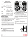
Installation Instructions
DS422i and DS426i Dual Beam Photoelectric
Intrusion Detection Systems
Wire Entrance
Response
Adjustment
GOOD
1.0 Specifications
• Range:
DS422i
DS426i
ACTIVE INFRARED SENSOR
Indoors
300 ft. (90 m)
600 ft. (180 m)
Outdoors
100 ft. (30 m)
200 ft. (60 m)
• Dimensions (HxWxD):
6.75 in. x 3.25 in. x 3.5 in.
171 mm x 82 mm x 87 mm
• Voltage:
12 to 28 VDC. Non-Polarized.
• Current:
Transmitter
15 mA
25 mA
DS426i
30 mA
25 mA
• Relay:
Power LED
Alignment
Voltage
Jacks
Vertical
Fine Tuning
Screw
Alignment
Tool
Intended for connection to DC power
supplies capable of supplying power if
primary power fails.
Alarm activated Form “C” with dry
contacts rated at 0.5 amps max. @
30 VAC and DC.
• Tamper:
Normally Closed with cover in place.
• Pointability:
The optical module can be adjusted
±90° horizontally or ±24° vertically.
• Temperature:
-13°F to +130°F (-25°C to +55°C).
POWER
ACTIVE INFRARED SENSOR
Note: Tool
may be in
any of four
positions
Receiver
DS422i
• Standby:
LEVEL ALARM
Optical Module
Receiver
Cover Screws
Transmitter
Figure A - Location of the system’s major items.
• Place the provided template onto the mounting surface and mark
the holes for its two mounting screws (supplied).
NOTE: Be sure all wiring is unpowered before routing.
• Route wiring (for wire size see Section 4.0) through the transmitter’s
wire entrance, leaving enough to properly wire the transmitter.
• Trigger Response Time:50 to 700 milliseconds, selectable.
• Mount the transmitter to the mounting surface. Firmly tighten the
screws.
2.0 Installation Considerations
• Repeat this complete mounting procedure for the receiver. Be sure
to mount the receiver in direct line-of-sight with the transmitter.
• Stay within the listed maximum range.
• Install the system with a clear line-of-sight between the transmitter
and receiver. If installed outdoors, make sure trees, weeds, plants,
etc. will not interfere with the beams.
• Use care when installing near reflective surfaces (i.e. glossy walls
or floors). Care should be taken during alignment to ensure beams
are line-of-sight aimed and are not reflecting off surfaces.
• Do not install the units where they may be immersed in water or
subject to corrosive liquids or sprays.
• Do not install the receivers where they will be facing an intense
source of light (e.g. a rising or setting sun). If the sun can not be
avoided, mount the receiver slightly higher than the transmitter. Aim
the receiver down at the transmitter.
3.2 Pole Mounting
NOTE: The recommended mounting height is 3 feet (1 m). However,
mounting height will change depending on the anticipated
intruder catch area.
NOTE: Use optional MB series poles or equivalent.
• Choose the appropriate mounting location. Install the poles with a
clear line-of-sight between the transmitter and receiver.
• Remove the transmitter’s cover by loosening the Cover Screw (see
Figure A).
• Firmly attach a mounting plate and U-clamp to the pole (see Figure
B) with the screws supplied. Make sure they are line-of-sight aimed
so the transmitter and receiver will be aligned.
• Do not install the receivers where sunlight could be reflected directly
into the receiver optics.
W iring Entrance
• Do not install either unit on movable surfaces or surfaces subject to
strong vibrations.
3.0 Mounting
U-clamp
3.1 Surface Mounting
NOTE: The recommended mounting height is 3 feet (1 m). However,
mounting height will change depending on the anticipated
intruder catch area.
• Choose the appropriate mounting locations. They should be rigid
and provide a clear line-of-sight between the transmitter and receiver.
• Remove the transmitter’s cover by loosening the cover mounting
screw (see Figure A).
Figure B - Pole assembly
NOTE:
Be sure all wiring is unpowered before routing.
• Route wiring (for wire size see Section 4.0) through the mounting
plate wire entrance (see Figure B), leaving enough to properly wire
the transmitter.
• Route the wiring through the transmitter’s wire entrance.
• Slide the transmitter onto the mounting plate. Tighten with the
mounting plate-to-unit screws.
• Repeat this complete mounting procedure for the receiver. Be sure
to mount the receiver in direct-line-of sight with the transmitter.
4.0 Wiring
5.0 Setup and Alignment
NOTE:
Precise, correct alignment is a critical process for these
systems to operate effectively.
• Apply power to the units.
• Check the transmitter. The Power LED (see Figure A) should be
on. If the lamp is not on, the unit is not receiving power.
• Locate the Alignment Tool (see Figure A) on either the Transmitter
or Receiver.
• Slide the Alignment tool up and out of its holder (see Figure F) and
slide it onto the Alignment Mount on whichever side of the
Transmitter is most convenient for sighting through the viewfinder.
Only apply power after all connections have been made
and inspected.
• Use the following chart (Figure C) to determine the minimum gauge
wire needed per length of wire run between the power source and
the last unit on the run. The chart is based on one system (one
transmitter and one receiver) connected to the same wire run from
the power source.
TRANSMITTER
SENSOR
If more than one system is added to the run, the maximum length
per gauge decreases and is determined by dividing the length found
in the chart by the number of systems on the run.
1
DS422i Wiring Chart
SIZE
12 VDC
24 AWG(0.6mm)
24 VDC
790 ft. (240m)
920 ft. (280m)
22 AWG(0.8mm) 1,640 ft. (500m)
LOT.
2
1,440 ft. (440m)
3
20 AWG(1.0mm) 2,560 ft. (780m) 2,300 ft. (700m)
18 AWG(1.2mm) 3,675 ft. (1120m) 3,280 ft. (1000m)
DS426i Wiring Chart
SIZE
12 VDC
24 AWG(0.6mm)
4
24 VDC
690 ft. (210m)
820 ft. (250m)
22 AWG(0.8mm) 1,410 ft. (430m)
1,250 ft. (380m)
Figure F - Positioning the Alignment Tool
20 AWG(1.0mm) 2,230 ft. (680m) 2,000 ft. (610m)
18 AWG(1.2mm) 3,215 ft. (980m) 2,850 ft. (870m)
Figure C - Wire chart
• From the side of the unit, look into the viewing port at the mirror.
The view in the mirror is what is in line-of-sight of the optical module.
• Wire the receiver and transmitter terminal strips (see Figures D and
E).
NOTE: Alignment may be made easier with the use of an alignment
light (see Section 8.0).
1
2
3
4
5
6
7
+
• Repeat this complete alignment sequence for the receiver’s optical
module.
POWER
ALARM
TAMPER
Figure D - Receiver Wiring
1
2
+
POWER
3
4
5
6
7
TAMPER
Figure E - Transmitter Wiring
Page 2
• Rotate the optical module until the
image of the other unit is centered
in the mirror (see Figure G). If
initially aimed too high or low, adjust
the Vertical Fine Tuning screw (see
Figure A) until the unit is centered. Figure G - Image in mirror
• When properly aligned the Receiver’s green GOOD LED should be
lit.
6.0 Fine-tune Alignment
Meter readings are very important in providing maximum trip-safety
margins (see Figure H). A 20,000 Ohm/volt (or greater) DC VOM is
recommended.
When fine-tuning the transmitter and receiver, maximum meter
readings occur at the transmitted beam’s center, which is also the
receiver’s line-of-sight. A reduction in the system’s effectiveness will
occur if the units are not properly aligned and fine-tuned.
© 2004 Bosch Security Systems
DS422i/426i Installation Instructions
7.1
Alarm response time
The system’s sensitivity to alarms is manually adjusted by the
RESPONSE TIME Control on the receiver (see Figure L1 and Table
L2).
Receiver's Line-of-Sight
Response Time
Control
3
4
2
+-
1
Transmitted Beam
RECEI V ER
Transmitted Beam strength is
strongest along this path
Transmitted Beam weakens
farther from its center
Figure L1 - Response Time Control
Figure H - Beam Strength Area
• Fine peak the transmitter. Connect the meter to the receiver’s test
terminals (see Figure J).
3
2
LEVEL
RESPONSE
TIME (ms)
SETTING
• Set the meter to read 3 to 5 VDC.
+-
5
RESPONSE
TIME
LEVEL
1
4
RESPONSE
SPEED
CATCH
EXAMPLE
1
50±25%
23 ft./s (7 m/s)
running
2
210±25%
4 ft./s (1.2 m/s)
jogging
3
380±25%
2.3 ft./s (0.7 m/s)
quick walk
4
540±25%
1.6 ft./s (0.5 m/s)
walking
5
700±25%
1 ft./s (0.3 m/s)
slow walk
5
RESPONSE
TIME
RECEI V ER
Table L2 - Response Settings
NOTE: Observe the Polarity
due to DC voltage.
Figure J - Meter connection
• Rotate the transmitter’s optical module very slightly to the right and
left until a maximum meter reading has been achieved. If you cannot
obtain a reading greater than 2.3 VDC, the Transmitter and Receiver
must be realigned using the procedure in section 5.0.
NOTE: To aid in fine-tuning the system, the red LEVEL LED gets
brighter as the units get fine-tuned and the green GOOD
LED will be on when the meter readings reach a peak.
• Adjust the transmitter’s Vertical Fine Tuning screw slightly until
maximum meter readings have again been achieved.
• With the transmitter’s optical module fine-tuned, repeat this exact
process with the receiver.
7.0 Final Check
• Completely block the upper beam on the transmitter. Neither the
ALARM LED nor the LEVEL LED should come on. If either does
come on, the beams are incorrectly aligned (see Figure K) and
should be re-aligned.
A setting near 1 will alarm if a person runs through the beam while a
setting near 5 will alarm for objects moving very slowly through the
beam. The setting should be adjusted lower where birds, debris,
etc., may interrupt the beam path. Be careful not to adjust the setting
too low, or it will not trigger an alarm.
NOTE: In order to comply with the requirements in UL 639, Intrusion
Detection Units, an object passing through the beams at a
speed of 8.8 feet per second (2.7 m/s) must trigger an alarm.
• Walk through the beams after the desired setting has been chosen.
Be sure the system alarms at the desired pace.
• Walk through the beams in several locations between the units
(see Figure M).
• The system should alarm
during each crossing of the
beam. If not, re-check
alignment or trigger
response time.
• Replace the covers.
Figure M - Walk testing the
system
NOTE: If a tamper circuit
has been installed, it should be tested now by lifting up the
appropriate covers.
• Secure the covers by tightening each cover mounting screw.
8.0 Other Information
8.1 Alignment Lights
Alignment may be made easier by using a flashing high intensity
light placed in front of the units. This makes a very distinct target
when looking at the other unit through the viewing port. A
recommended light source is model AL402.
8.2 Maintenance
At least once a year the front covers should be cleaned. Use a clean
cloth and a common window cleaner.
On a daily basis, the end user should walk through the beams before
arming. This will verify operation.
Figure K - Mis-aligned beams
• Completely block the lower beam of the transmitter. Again, neither
the ALARM LED nor the LEVEL LED should come on.
• If necessary, re-align and fine-tune each unit.
DS422i/426i Installation Instructions
© 2004 Bosch Security Systems
Page 3
9.0 Application Tips
9.2 Perimeter Protection
When using photoelectric detectors for motion detection, there are a
few installation techniques that will make the system more versatile.
When protecting the interior of an installation, a good technique is to
mount the units at 90° angles around the coverage area (see Figure
R).
9.1 Beam Stacking
Beam stacking gives a wall
of protection by stacking
several units at different
R1
T1
heights and providing an
alarm activation on the
blockage of only one pair of S
beams (see Figure N for the
correct set-up technique).
Note that the system is
T2
installed with alternating R2
D
transmitters and receivers at
each end. This eliminates the
possibility of a receiver being
Figure N - Beam stack method
covered by more than one
transmitter.
The maximum spacing between receivers (S) can be calculated by
dividing the distance between the transmitter and its receivers (D) by
20.
Therefore, if the distance between a transmitter and receiver is 100
ft. (30 m), the maximum spacing between receivers would be 100 ft.
(30 m) ÷ 20, or 5 ft. (1.5 m)
S = D/20 S = 100 ft. (30 m)/20 S = 5 ft. (1.5 m)
A potential problem when installing systems in a beam stack is “Near
Field Reflection.” Near field reflection is caused when a reflective
object is placed in the line-of-sight of the detectors and causes the
transmitted signal to be reflected to the wrong receiver (see Figure
P).
R4
T2
T1
R1
R3
T3
R2
T4
Figure R- Perimeter protection
Note that the beams are mounted so they cross each other. This way,
an intruder can not enter the area by walking between the units.
When installing multiple transmitters and receivers, test with all the
receivers powered-up, but with only one transmitter powered-up at a
time. A transmitter should set up only its receiver.
Receivers physically too close to a different system’s transmitters
may be set up even if the transmitter is not pointed at them (see
Figure T).
R1
T1
Figure T - Close proximity field problem
T2
R2
Figure P - Near field reflection
It may be desirable to have more than two sets of beams to create
taller stacks. This can be accomplished by adding receivers as shown
in Figure Q). Note that the beam from each transmitter is covering
two receivers.
T1
R1
R3
R2
R4
T2
If a receiver is being set up by the wrong transmitter, the signals can
usually be eliminated by masking the sides of the transmitter and
receiver. Use electrician’s tape or duct tape inside each enclosure’s
window.
When installing these systems, remember that the infrared signal may
reflect off objects (e.g. glossy walls or floors) in the coverage area and
still set up the receiver.
A thorough walk test performed at several different points within the
coverage area will catch this problem. Re-aligning the units should
solve this problem.
The only way to insure proper continual protection is to perform
regular walk tests of the desired coverage area.
Figure Q - Multi-system stack
© 2004 Bosch Security Systems
130 Perinton Parkway, Fairport, New York, USA 14450-9199
Customer Service: (800) 289-0096; Technical Support: (888) 886-6189
03/04
DS422i/DS426i Installation Instructions
P/N: 44974D Page 4