1
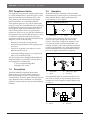
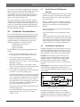
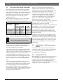
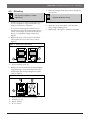
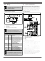
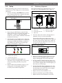
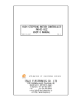
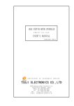
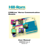
D296/D297
Installation Instructions
EN Long-Range Beam
Smoke Detectors
D296/D297 | Installation Instructions | 1.0
Description
FCC Compliance Notice
2.0
This equipment was tested and complies with the limits
for a Class B Digital Device, pursuant to Part 15 of the
Federal Communications Commission (FCC) rules.
These limits provide reasonable protection against
harmful interference in a residential installation.
Each D296 and D297 Transmitter sends an invisible
infrared beam of a specific frequency and intensity. Each
D296 and D297 Receiver detects and measures the
beam’s intensity (refer to Figure 1).
This equipment generates, uses, and can radiate radio
frequency energy. If not installed and used according to
the manufacturer's instructions and recommendations,
this equipment might cause harmful interference to
radio communications. There is no guarantee that
interference will not occur in a particular installation. If
this equipment does cause harmful interference to radio
or television reception, determined by turning the
equipment on and off, try correcting the interference by
doing one or more of the following:
•
Reorient or relocate the receiving antenna.
•
Increase the separation between the equipment and
the receiver.
•
Connect the equipment to an outlet on a circuit
different from the receiver.
•
Contact the installing company or an experienced
radio or TV technician for help.
The FCC booklet How to Identify and Resolve Radio-TV
Interference Problems (stock number 004-000-00345-4)
can be helpful. It is available from:
Operation
Figure 1: Infrared Transmission
1
3
2
1 - Transmitter
2 - Beam
As smoke obscures the beam, the receiver senses a
decrease in the signal strength and measures that
decrease. The receiver compares the signal level with
two preset thresholds: an alarm threshold that is set
using the sensitivity switch and a trouble threshold that
is preset at approximately 10%. If the signal falls below
the alarm threshold for the programmed alarm period,
the receiver signals an alarm (refer to Figure 2).
Figure 2: Beam Obscuration
1
4
2
U. S. Government Printing Office
Washington, DC 20402
1.0
3 - Receiver
3
Description
The D296 and D297 Long-Range Beam Smoke
Detectors have a separate transmitter and receiver.
Internal pointability provides coverage flexibility
without brackets. Automatic signal synchronization and
range adjustment reduce installation costs. Selectable
sensitivity and alarm response time provide installation
flexibility.
1 - Transmitter
2 - Beam
3 - Obscuring object
4 - Receiver
If the signal falls below the trouble threshold for more
than 20 sec (caused by an object blocking the beam for
example), the receiver signals a trouble condition (refer
to Figure 3).
Figure 3: Beam Blockage
1
4
2
3
1 - Transmitter
2 - Beam
2
3 - Blocking object
4 - Receiver
Bosch Security Systems, Inc. | 09/06 | 31344F
D296/D297 | Installation Instructions | 3.0
The receiver automatically compensates for the gradual
signal loss because of dust and dirt buildup on the cover.
After a signal loss of 50%, the receiver indicates a
trouble. When the dust and dirt buildup are cleaned or
the blockage is removed, the detector automatically
returns to its normal operation level.
The receiver indicates a trouble if the beam strength
increases by more than 20% for longer than 20 sec. A
trouble can be caused by an initial misalignment or the
removal of a partial beam blockage during alignment.
Perform a fine-tune alignment as described in Section 6.3
Fine-Tune Alignment on page 8.
3.0
Installation Considerations
Correct D296 and D297 location and spacing is critical
in a properly installed and operating fire alarm system.
For best results, place the detectors and space them
according to the National Fire Protection Association
(NFPA) Standard 72, The National Fire Code. This
standard is available at a nominal cost from:
NFPA Protection Association
Batterymarch Park
Quincy, MA 02269
In all installations, good engineering judgement must
prevail.
•
Do not use mirrors. Install detectors with a clear
line-of-sight between the transmitter and receiver.
•
Clear the beam path of moving objects.
•
Set sensitivity based on the distance between the
transmitter and receiver (refer to Section 6.2 Sensitivity
Adjustment on page 8).
•
Mount detectors directly to the ceiling or to side
walls. Do not mount them where the beam path runs
parallel within 4 in. (10.2 cm) of a corner.
•
For a sloped or peaked ceiling, ensure the beam path
is within 3 ft (1 m) of the ceiling’s peak.
•
Air stratification might prevent smoke from reaching
detectors mounted close to the ceiling. Stratification
occurs when smoke, rising because it is warmer than
the surrounding air, reaches a level where it is the
same temperature as the surrounding air and does not
rise to the ceiling. If this is possible, install extra
beams where stratification is expected.
•
Avoid areas with normal smoke concentrations, such
as kitchens and garages.
•
Do not install detectors where the normal ambient
temperatures are below -22°F (-30°C) or above
+130°F (+54°C).
Bosch Security Systems, Inc. | 09/06 | 31344F
3.1
Installation Considerations
Avoid Heat and Air Movement
Sources
•
Place the D296 and D297 Detectors where the beam
path does not pass near heating and cooling outlets.
•
Do not mount where hot or cold air blows directly
into the beam path.
•
Heating, ventilating, and air conditioning (HVAC)
systems can blow smoke away from the beam path.
Smoke must accumulate in the beam path to be
detected.
•
Do not mount heaters close to the beam path. Heat
can distort the beam.
•
Test for beam distortion by monitoring the signal
voltage.
•
After setup, the detector’s signal voltage must read
4 VDC. Monitor the voltage and turn on all heating
and cooling devices in the area. The signal voltage
must not fluctuate more than 0.20 VDC. If it does,
relocate the detector to avoid these disturbances.
3.2
Avoid Bright Light Sources
Sunlight and light from extremely bright sources such
as the exposed bulbs of high-pressure sodium, mercury
vapor, and metal halide lights can cause stray signals.
Do not point the receiver toward any of these sources.
Sunlight: Do not point the receiver directly at the
rising or setting sun. If installing the receiver where
sunlight cannot be avoided, mount it slightly higher
than the transmitter and aim it down toward the
transmitter. This causes the receiver to look below the
horizon.
Bright Lights: Do not mount the receiver where it looks
at exposed bulbs of high-pressure sodium, mercury
vapor, and metal halide lights. Refer to Figure 4 to avoid
exposed lights.
Figure 4: Avoiding Exposed Lights
1 - Receiver
2 - Do not place bright lights in this area.
Bare fluorescent lights can also create a problem,
especially in long hallways where a series of lights are
perpendicular to the beam. Incandescent lights are not a
problem as long as they are not directly in the beam
path.
3
D296/D297 | Installation Instructions | 3.0
3.3
Installation Considerations
Use Correct Wire Gauge and Length
Beam smoke detectors are often used to protect large
areas, requiring long wire runs to power the detectors
and signal alarm conditions. The voltage available at the
end of long wire runs might not be sufficient to power
the detector, especially when the system is running on
battery backup. Use the correct wire gauge when
installation detectors.
Refer to Table 1 for the proper wire size, wire length,
and the number of transmitter and receiver pairs.
Table 1:
Wire Gauge and Length
Wire Length
Wire Size
500 ft (152 m)
1000 ft (304 m)
14 AWG
(1.8 mm)
20 pairs
10 pairs
16 AWG
(1.5 mm)
13 pairs
6 pairs
18 AWG
(1.2 mm)
8 pairs
4 pairs
2500 ft (762 m)
5000 ft (1524 m)
4 pairs
2 pairs
3 pairs
1 pair
2 pairs
1 pair
3.4
Provide a Stable Mounting Surface
Always select stable mounting surfaces.
Beam smoke detectors depend on the projected beam
measurement to sense smoke. Trouble or alarm
conditions can be caused by shifts in beam alignment
when the transmitter or receiver moves.
Never mount a detector to a suspended support, such as
a pipe or length of wood that is supported at only one
end. This type of mounting can create a pendulum effect
that greatly multiplies even very small movements at
one end of the support. For example, a 2 in. (5.1 cm)
movement translates into a beam misalignment of more
than 20 ft at 350 ft (6 m at 107 m). Support mounting
surfaces at opposite corners to reduce the pendulum
effect.
Always select surfaces that are not subject to building
movement. The D296’s and D297’s automatic
compensation circuits eliminate most problems created
by normal building expansions and contractions. In
some unusual circumstances, the walls and support
structure might be subject to more significant movement
because of heavy equipment operation, such as cranes
anchored to the top of the walls.
4
When you are uncertain about mounting surface
stability, measure the detector’s signal voltage. This
voltage must be 4 VDC. Beam misalignment can cause
this voltage to increase or decrease. The detector
indicates a trouble condition when the voltage increases
to greater than 4.8 VDC or decreases to less than
2 VDC over a long period. A trouble condition also
occurs when voltage decreases to 0.4 VDC for more
than 20 sec. Refer to Section 7.3 Reference Voltage
Calibration on page 9 for voltage reading.
If you expect the mounting surface to move, relocate the
detector to a stable surface or add supports to the
mounting surface to prevent movement.
Mounting the detector to a square or octagonal electrical
mounting box of 4 in. (10 cm) can bow the mounting
plate. Bowing can occur because the mounting box
screw tabs are below flush with the top edges of the
mounting box. Overtightening the mounting screws
bows the mounting plate inward at the bottom, causing
the optics to aim low.
Irregularities in the flatness of the mounting box edge
surfaces or screw tabs worsens this condition. Only use
mounting boxes with flat, regular surfaces and properly
formed screw tabs. Tightening the mounting screws to
secure the mounting plate to 2 in. (5 cm) or 2 lb (0.9 k)
torque minimizes misalignment caused by mounting
plate bowing.
3.5
Stratification in Cold Environments
Effects
In extremely cold environments such as unheated
warehouses, smoke cools very quickly and is less likely
to rise to the ceiling. Add more detectors at lower
mounting heights to compensate.
3.6
Expected Fire Load
When designing a fire alarm system, allow for expected
fire loads within the application. For example, fires
caused by the ignition of flammable petroleum-based
liquids generally lead to a rapid buildup of heavy
smoke. When this type of fire is probable, use sensitivity
settings 0 or 1 for a 5-sec response time.
Bosch Security Systems, Inc. | 09/06 | 31344F
D296/D297 | Installation Instructions | 4.0
4.0
4. Route the wiring from the electrical box through the
wire entrance.
Mounting
Do not use this product in outdoor
applications.
1.
Mounting
Unpower (disable) all wiring.
Install a 10 cm (4 in.) square or octagonal electrical
box (not supplied) to a rigid surface that is not
subject to movement or vibrations.
If you are not mounting these detectors to an
electrical box, ensure the surface cannot move or
vibrate. For example, do not mount the detector
directly to a suspended ceiling without extra
support.
5. Mount the back plate to the electrical box.
6. Attach the circuit carrier plate to the back plate
using a single mounting screw.
7.
Repeat Steps 1 through 6 to mount the transmitter.
2. Remove the screw on the receiver's access door.
Then remove the cover’s four screws (refer to
Figure 5).
Figure 5: Access Door and Cover
2
2
1
1 - Access door
2 - Cover mounting screw (4)
3. Remove the receiver back plate by unscrewing the
single mounting screw from the top of the circuit
board carrier plate and separating the two plates
(refer to Figure 6).
Figure 6: Removing the Back Plate
1
2
4
3
1
2
3
4
-
Remove screw to expose the back plate.
Mounting slot (4)
Wiring entrance
Do not remove.
Bosch Security Systems, Inc. | 09/06 | 31344F
5
D296/D297 | Installation Instructions | 5.0
5.0
Wiring
5.1
Wiring
Only apply power after all connections are
made and inspected.
Refer to Figure 7 and Table 2 when wiring the
transmitter and receiver terminals.
Figure 7: Wiring a Single D296 or D297 Detector
AUX.
RELAY
ALARM
FIRE
TRBL
ALARM ALARM VDC
4
1
2
3
4
5
6
7
Remote Indicator Plate
The D306 Remote Indicator Plate is shipped with the
D296 as a standard accessory. Although the D306 is not
required, the manufacturer recommends its installation
to check the detector’s condition from ground level. If
using either a D306 or D307 Remote Indicator Plate,
install the remote indicator connector to the receiver
now (refer to Figure 8).
Figure 8: D306 Remote Indicator Plate Connection
1
–
+
8
9
Alarm Loop
2
Power Loop –
Power Loop +
1
2
3
4
-
1
2
–
+
3
Receiver
End-of-line (EOL) resistor
Transmitter
Fire Alarm Control Panel (FACP)
Do not install on verified fire circuits.
Do not coil excess wiring inside the units.
Table 2:
Transmitter and Receiver Terminals
Type
Terminal
Terminal
1 and 2
Receiver
1, 2, and
3
Receiver
4 and 5
Receiver
6 and 7
Receiver
8 and 9
Description
Input power terminals. Refer to
Section 11.0 Specifications on
page 14 for operating voltages.
Form “C” auxiliary relay contacts.
Terminals 1 and 2 open on Fire
alarm; Terminals 2 and 3 close
(short) on Fire alarm.
Normally Open Fire alarm
contacts close (short) on Fire
alarm.
Normally Closed Trouble contacts
open for Trouble alarm.
Input power terminals. Refer to
Section 11.0 Specifications on
page 14 for operating voltages.
To reset after a Fire alarm, interrupt power
to the receiver for a minimum of 1 sec. If the
fire panel does not allow you to reset, install
a switch in series with Terminal 8.
6
1 - D306 Remote Indicator Test Plate Connector*
2 - D296/D297 Receiver
3 - EOL
4 - FACP
5 - D306 Remote Indicator Plate
Wiring: a = orange c = black e = yellow g = violet
b = blue
d = red
f = green
* Refer to Section 7.5 Remote Test Indicator Plate
Connector on page 10 for the Remote Test.
1.
Place the D307 no farther than 100 ft (30.5 m) from
the receiver and wire with 18 AWG (1.2 mm) or
larger wire. You can wire the D306 a maximum of
500 ft (152 m) from the receiver.
2. Slide the remote indicator connector over the pins
located to the right of the receiver’s terminal strip.
Refer to the D307 Installation Instructions (P/N:
32071) if you are connecting a D307.
Bosch Security Systems, Inc. | 09/06 | 31344F
D296/D297 | Installation Instructions | 6.0
6.0
6.1
Setup
Before performing a setup, ensure all connections are
made and secure. Then, apply power to the transmitter
and receiver.
1.
Setup
Preliminary Alignment
Each optical module has two alignment mirrors, one on
each side, for an initial alignment (refer to Figure 11).
Figure 11: Optical Module
Press the transmitter’s Aim Mode button, located
above the green LED (refer to Figure 9) allowing it
to power up while the cover is off.
2
1
Figure 9: Transmitter Circuit Board Showing Aim
Mode Button
4
3
1
2
1 - Aim Mode button
7
5
2 - Green LED
2. Ensure the green LED flashes on and off. If this
LED is off, check for power and proper polarity on
Terminals 1 (–) and 2 (+). If the green LED is
steadily lit, you have a faulty transmitter. Return the
transmitter to the factory.
1
2
3
4
1.
Vertical fine tune
Front view
Horizontal fine tune
Side view
5
5 - Alignment mirror (3)
6 - Rear bore sight (2)
7 - Front bore sight
Look into either mirror from a side angle that is a
minimum of 2 ft (61 cm) from the module.
The optical module points at objects seen in the
mirror when the orange-colored front bore sight is in
the center of the rear bore sights (refer to Figure 12).
Use the rear and front sights in the same way as you
use sights when aiming a gun.
3. Check the three receiver LEDs (refer to Figure 10).
It is normal for all three LEDs to be on at this time,
with the green LED either flashing or steadily on.
If all LEDs are off, check for power and proper
polarity on Terminals 8 (–) and 9 (+).
Figure 10: Receiver LEDs
-
6
Figure 12: Alignment Mirror
1
2
1
1 - Alarm LED (red)
2 - Trouble LED (yellow)
3 - Normal LED (green)
4. Mount a D309 Strobe Aiming Light or an
equivalent, such as a Faraday 5508, as close to the
receiver as possible, preferably on top of the
receiver.
5. Point the D309 at the transmitter using it as your
aiming guide. An aiming light might not be
necessary for short distance separations.
1 - Rear bore sight (2)
2 - Front bore sight
2. Rotate the transmitter's optical module left or right
until you see the aiming light image (or receiver
image, if aiming light is not used) in the mirror.
3. If optical module is initially aimed too high or too
low, adjust the Vertical Fine Tuning adjustment Allen
screw (with the supplied Allen wrench) slightly up or
down until you see the image.
4. Use the Vertical Fine Tuning adjustment screw and
the Horizontal Fine Tuning adjustment screw to fine
tune the image to the center of the mirror (aligned
with the front and rear bore sights).
5. Replace and secure the transmitter's cover.
6. Ensure the transmitter's green LED is flashing.
7.
Bosch Security Systems, Inc. | 09/06 | 31344F
Replace and secure the transmitter's access door.
7
D296/D297 | Installation Instructions | 6.0
Setup
8. Align the receiver to the transmitter image
following Steps 1 through 7.
9. Ensure the receiver's green LED is flashing,
indicating the preliminary alignment is complete.
10. If the receiver’s green LED is not flashing, repeat
Steps 1 through 9 for the receiver.
6.2
1.
1.
Connect the D1005 Test Cable (supplied) to Pins 1,
2, and 3 of P6. These pins are located to the right of
the receiver’s terminal strip (refer to Figure 14).
Figure 14: D1005 Connection
1
Sensitivity Adjustment
Select the appropriate sensitivity setting based on
the distance between the transmitter and receiver.
(refer to Table 3 which lists distances including
some settings that overlap). Select a lower setting
for a more sensitive detection or select a higher
setting for better immunity to false alarms.
Table 3:
Sensitivity Settings
Switch
Setting
0
Sensitivity
30%
Alarm
Response
5 sec
1
60%
5 sec
2
20%
30 sec
3
30%
30 sec
4
40%
30 sec
5
50%
30 sec
6
60%
30 sec
7
6.3 Fine-Tune Alignment
70%
30 sec
a
c
b
1 - Connector wires (a = white, b = red [+],
c = black [-]
Beam Length
30 ft to 100 ft
(9 m to 31 m)
100 ft to 350 ft
(31 m to 107 m)
30 ft to 50 ft
(9 m to 15 m)
45 ft to 75 ft
(14 m to 23 m)
70 ft to 100 ft
(21 m to 31 m)
90 ft to 140 ft
(27 m to 43 m)
120 ft to 180 ft
(37 m to 55 m)
160 ft to 350 ft
(49 m to 107 m)
8*
9*
* Do not use positions 8 and 9. They are not valid.
2. Set the receiver’s Sensitivity switch to your selected
setting. The Sensitivity switch is located to the right
of the optical module. The indicator, or pointer
marking, runs along the side of the switches' shaft
(refer to Figure 13).
If the Remote Indicator Plate connector is installed,
temporarily disconnect it.
2. Connect a 20,000 Ω/VDC VOM (or greater) to the
D1005’s black (–) and red (+) leads. Set the meter
scale so you see the readings ranging from 0 VDC
to 5 VDC.
3. Check the three receiver LEDs on the receiver.
If the receiver gets the beam, the green LED flashes
and the red and yellow LEDs are steadily on.
If the green LED is steadily on, the beam is not
reaching the receiver. Realign according to the
procedure described in Section 6.1 Preliminary
Alignment beginning on page 7.
4. Observe the meter readings. Adjust the receiver’s
optical module using the horizontal and vertical
fine-tuning adjustment screws for a maximum meter
reading.
This is the most critical alignment process.
For the most effective system operation,
ensure you have peak voltage during the
fine-tune alignment.
When performing fine-tune alignment, keep
your arms and hands away from the front of
the receiver and out of the beam path.
Figure 13: Sensitivity Switch
0
The maximum voltage peak reading varies,
depending on the distance between the transmitter
and receiver. The acceptable peak voltage range is
from 0.50 V to 5.00 V. The voltage at the receiver is
greater at shorter distances.
Make a note of the alignment voltage. It might be
helpful if you need to troubleshoot at another time.
8
Bosch Security Systems, Inc. | 09/06 | 31344F
D296/D297 | Installation Instructions | 7.0
Peak the voltage to ensure a stable and
trouble-free detector.
5. After completing the fine-tune alignment, remove
the test cable.
6. Replace and secure the receiver’s cover.
7.
Check the status of the receiver’s green LED to
ensure it is still flashing.
8. With the meter still connected to the test cable,
reinstall this cable to P6. Route the test cable
through the opening in the cover (white lead towards
center of the receiver).
9. At this point, you can perform an Alarm Test.
Connect the D1005’s white and black wires. Reset
the receiver by temporarily removing power.
10. Press the receiver’s Setup button, located below the
P6 and test cable connection (refer to Figure 15).
Additional Information
7.0
Additional Information
7.1
Fire Alarm Reset
1.
Reset the receiver after a fire alarm by removing
power from the receiver for at least 1 sec.
2. Reapply power (refer to Section 7.4 Power Outage).
7.2
1.
Cleaning
Clean the outside of the covers a minimum of once
each year. Use a common window cleaner and a soft,
clean cloth. Under normal conditions, there is no
Trouble alarm if the beam is not continuously
blocked longer than 18 sec.
2. Recheck the reference voltage. If voltage is less than
3.8 VDC or greater than 4.2 VDC, calibrate the
receivers (refer to Section 7.3 Reference Voltage
Calibration).
Clean covers are necessary for proper
reference voltage readings.
Figure 15: Receiver Setup Button
1
7.3
2
1 - LEDs
1.
2 - Setup button
Only press the Setup button if the covers
are on both the transmitter and receiver.
A 1-min to 2-min automatic internal setup process
begins. This setup ends in a reference voltage that is
used to measure beam blockages.
The red and yellow LEDs turn off and the green
LED turns steadily on. After some voltage
fluctuations, the meter sets to 5.0 VDC.
During this time, do not block the beam or
move the units.
11. At the end of the setup, the receiver’s green LED
flashes and the voltage decreases to a range from
3.8 VDC to 4.2 VDC. Use this voltage as a
reference when you compare later readings to
determine the need for cleaning. If the voltage is not
within this range, press the Setup button.
Reference Voltage Calibration
Check the detector’s reference voltage a minimum
of once each year. Check the voltage more often if
required by local regulations or AHJs.
2. Remove the receiver access door and measure the
reference voltage using the supplied test cable. You
can also measure the voltage at the D307 (if used).
3. If the voltage is less than 3.8 VDC, remove the
cover and use the Setup switch to perform a
fine-tune alignment.
If the voltage is greater than 4.2 VDC, press the
Setup button. You do not need to calibrate if the
voltage is between 3.8 VDC and 4.2 VDC.
7.4
Power Outage
When power is removed and reapplied to the receiver,
such as in a power outage or alarm reset, the original
reference voltage information is lost.
If the cover is on during powerup, the receiver
automatically restarts the internal setup process for a
new reference voltage when power is applied. If the
cover is off, reattach it and press the Setup button.
12. After setup, remove the test cable.
13. Reconnect the D306 connector if used.
14. Replace and secure the access door.
Bosch Security Systems, Inc. | 09/06 | 31344F
9
D296/D297 | Installation Instructions | 7.0
7.5
1.
Additional Information
Remote Test Indicator Plate
Connector
Momentarily attach the connector’s orange and
black leads to produce a Test alarm (refer to
Figure 16).
For example, if the expected smoke density is
0.5%/ft (0.5%/30 cm), the obscuration at 50 ft (15 m) is
20%. The obscuration at 250 ft (95 m) is 73% (refer to
Figure 17).
Figure 17: Smoke Density and Obscuration Chart
Figure 16: Remote Indicator Plate Connector
1
2
3
4
5
6
1
2
3
4
5
6
-
Remote Alarm Test (orange wire)
Analog reference voltage out (blue wire)
Common (-) (black wire)
Red LED (red wire)
Yellow LED (yellow wire)
Green LED (green wire)
2. For a Remote Test, install a momentary switch
between the orange and black wires.
3. Connect the black and blue wires to an analog
meter for reference voltage measurements.
4. Connect the red, yellow, and green wires to remote
LEDs.
Each lead wire is current limited to a maximum of
10.0 mA DC.
7.6
Smoke Density and Obscuration
The total obscuration of the infrared beam depends on
the density and width of the smoke cloud along the
beam path. As the width of the smoke cloud increases,
less dense smoke is needed for an equal obscuration of
the beam path. Assume the smoke cloud is the entire
distance of the beam path. Select the total obscuration
needed for an alarm by setting the Sensitivity Pot
according to Section 6.2 Sensitivity Adjustment on page 8.
1
2
3
4
-
Smoke density
UL minimum sensitivity
UL maximum sensitivity
Distance between transmitter and receiver
Refer to Table 4 for the sensitivity pot settings, total
obscuration, needed for an alarm.
Table 4:
Sensitivity Pot and Obscuration
Sensitivity Pot Setting
Total Obscuration at Alarm
2
0 or 3
4
5
1 or 6
7
20%
30%
40%
50%
60%
70%
Total beam obscuration by smoke increases with the
distance between detectors; there is more smoke within
the beam path. Therefore, you can lessen detector
sensitivity by increasing the distance. Detector
sensitivity is also less at greater distances because
obscuration by other contaminants, such as dust,
increases.
Set detector sensitivity to respond to the proper smoke
obscuration and to reduce the chance of a false
activation.
10
Bosch Security Systems, Inc. | 09/06 | 31344F
D296/D297 | Installation Instructions | 7.0
7.7
Additional Information
Field Sensitivity Measurements
The D296 and D297 automatically compensate for the
effects of dust and dirt accumulation on their covers.
They also compensate for component aging. The NFPA
requires the detector sensitivity be measured in the field
within one year after its initial installation and every
alternate year thereafter (refer to NFPA 72).
Order a D308 Test Kit to test detector sensitivity in the
field. Refer to Table 5 for alarm information for the
D308 filters and the Sensitivity Test Kit provided with
the detectors.
Table 5:
Sensitivity and Response
Sensitivity Setting
Must Not Alarm
Must Alarm
2
0 or 3
4
5
1 or 6
7
0% (no filter)
0% (no filter)
20% (filter)
20% (filter)
40% (filter)
40% (filter)
40% filter
60% filter
60% filter
80% filter
80% filter
80% filter
Use the Sensitivity Test Kit to check detector sensitivity
only during installation. For field testing, use the D308.
Each filter decreases the detector’s signal by a specific
amount. When you place a filter in front of the receiver’s
optical module for a minimum of 30 sec
(5 sec for position 0 or 1), you can determine the
approximate sensitivity setting of the installed detector
by its response as shown in Table 5.
Testing these detectors activates a Fire
alarm. Inform all concerned personnel
before performing a test.
Bosch Security Systems, Inc. | 09/06 | 31344F
11
D296/D297 | Installation Instructions | 8.0
8.0
Troubleshooting
Troubleshooting
Table 6:
Troubleshooting
Transmitter
LED
Condition
Solution
Flashing
Normal
Off
1. There is no power at the transmitter.
1. Restore power to Terminals 1 and 2.
2. The Aim Mode button not pressed.
2. Press the Aim Mode button.
3. The transmitter is faulty.
3. Replace the transmitter.
Receiver – Aim Mode
Red Yellow
Green Terminals Terminals Condition
Solution
LED
LED
LED
4 and 5
6 and 7
On
On
Flashing Open
Open
The alignment is acceptable.
On
On
On
Open
Open
The beam is blocked or the
Clear the beam path or
receiver is misaligned.
realign the receiver.
On
Flashing Flashing Open
Open
The sensitivity setting is invalid.
Set the receiver to the
proper setting.
On
Off
Off
Open
Open
There is no power.
Check for power at
Terminals 8 and 9.
Receiver - Normal Mode
Off
Off
On
Open
Closed
The receiver is initializing. It
stabilizes in 60 sec to 120 sec
Off
Off
On
Open
Open
The receiver is initializing. The
Replace the access
access door is missing or
door.
loose.
Off
Off
Flashing Open
Closed
Normal.
Off
Off
Flashing Open
Open
The access door is missing or
Replace the access
loose.
door.
Off
On
On
Open
Open
Trouble. Beam is blocked or
Clear the beam path or
misaligned.
realign the receiver.
Off
On
Flashing Open
Open
Trouble. If the reference voltage Clean the transmitter
is less than 2 VDC, dust on the
and receiver covers. If
lens reduced the signal
the reference voltage
strength or vibration misaligned does not return to 4
VDC, realign the receiver
the receiver.
and press the Setup
switch.
Off
On
Flashing Open
Open
If the reference voltage is
Perform a fine-tune
greater than 4.8 VDC, the
alignment of the receiver
beam strength increased
and use the Setup
because an initial beam
button.
misaligned or a partial blockage
was removed at setup.
On
Off
Flashing Closed
Closed
Alarm.
Determine the cause of
the alarm and reset the
receiver.
On
Off
Flashing Closed
Open
Alarm. The access door is
Determine the cause of
the alarm and reset the
missing or loose.
receiver. Replace the
access door.
On
On
On
Closed
Open
Alarm and Trouble. An alarm
Determine the cause of
occurred, then the beam was
the alarm and reset the
receiver. Clear the beam
blocked.
path.
12
Bosch Security Systems, Inc. | 09/06 | 31344F
D296/D297 | Installation Instructions | 9.0
9.0
Installing Multiple D296 and D297 Detectors
Installing Multiple D296 and D297 Detectors
For smooth, flat ceilings, mount the detectors so there is spacing of no more than 60 ft (18.3 m) between beam paths
(with no more than half of this spacing between the beam path and side wall, the wall parallel to the beam path).
Other spacings depend on ceiling height, air flow characteristics, and response requirements. The minimum spacing
between adjacent detectors is 1/10th the distance between the transmitter and receiver. For example, if the beam
length is 300 ft (91 m), place the detectors a minimum of 30 ft (9.1 m) apart. Refer to Figure 18 for layout placement.
Figure 18: Transmitter and Receiver Placement
1 - Receiver
2 - FACP
3 - Transmitter
4 - EOL resistor
5 - 60 ft (16.3 m) maximum
When two or more adjacent detectors are installed in the same area, alternate the transmitter and
receiver locations. If the transmitter and receiver are not alternated, ensure the spacing between the
detectors is 1/5th the distance from the transmitter to the receiver.
Bosch Security Systems, Inc. | 09/06 | 31344F
13
D296/D297 | Installation Instructions | 10.0 Quick Start Installation Flowchart
10.0 Quick Start Installation Flowchart
Figure 19: Quick Start Installation Flowchart
Start
TX = Transmittter
RX = Receiver
• Mount TX and RX
according to
Section 4.0 Mounting
on page 5 and the
applicable fire codes.
Is the
green LED
on the TX
blinking?
• At the TX, press the
Aim Mode button.
• Apply power to the TX
and RX.
• The green LED is off.
Check the power.
No
• The green LED is
steadily on.
Call Bosch.
• Go to the TX.
Yes
• No LED = No power.
• LED steadily on = Not
seeing the TX.
• Flashing yellow LED =
Invalid sensitivity
setting (refer to Table 3
on page 8).
• At the RX, set the
sensitivity according to
Table 3 on page 8.
• Point the TX at the RX
using the alignment
sight.
• Point the RX at the TX
using its alignment
sight for the initial
adjustment.
• Fine tune using the
Allen wrench
(supplied).
• Recheck the RX
alignment and clear
the beam path.
• The TX alignment is
complete.
• Replace the housing
and access cover.
• Is the
green LED
on the RX
flashing?
No
• Are the red and
yellow LEDs on
the RX
steadily
on?
• Attach the test cord
through the access
door.
• Press the Setup
button to begin the
2-min Learn Mode.
• Remove the test cable
and replace the outer
cover.
• Do not block either
the TX or RX during
this mode.
• Remove the access
door.
• Go to the RX.
Yes
• Attach the test cord to
Terminals 2 and 3 of
the P6 connector
(refer to Figure 14 on
page 8).
• Check the voltage
using 20,000 Ω/VDC
VOM.
• Optimize the voltage
reading according to
Figure 15 on page 9 .
Use the Allen wrench
to fine tune.
• Is the
green LED
flashing?
• Press the Setup button
again.
• Is the meter
voltage between
3.8 VDC and
4.2 VDC?
No
• If still unsuccessful,
recheck the RX
alignment.
• Alignment is complete.
• Remove the test cable.
Yes
• Connect the D307
Remote Test Indicator
Plate to P6, if used.
Verify the operation
using the test filters
(supplied).
End
• Replace the access
door.
14
Bosch Security Systems, Inc. | 09/06 | 31344F
D296/D297 | Installation Instructions | 11.0
Specifications
11.0 Specifications
Table 7:
Specifications
Operating Voltage
Standby Current
Receiver Alarm
Current
Range (the distance
between the
transmitter and
receiver)
Spacing (the distance
between the systems)
Pointability
Sensitivity
Alarm Contacts
Trouble Contacts
Auxiliary Alarm
Contacts:
Tamper
System Signaling
Signal Delay
Temperature
Mounting
Listings
and Approvals
Standard
Accessories
Optional
Accessories
D296: 18.0 VDC to 32.0 VDC
D297: 10.2 VDC to 15.0 VDC
D296 Receiver: 45 mA at 24 VDC
D296 Transmitter: 20 mA at 24 VDC
D297 Receiver: 50 mA at 12 VDC
D297 Transmitter: 20 mA at 12 VDC
D296: 70 mA maximum
D297: 75 mA at 12 VDC
30 ft to 350 ft (9 m to 107 m)
Allow no more than 60 ft (18 m) between systems. Spacing of 60 ft (18 m) is confirmed by
Underwriters Laboratories, Inc. (UL) testing.
Internally pointable optics for ±90° horizontal, and ±10° vertical adjustment.
Field selectable for 20%, 30%, 40%, 50%, 60%, or 70% beam obscuration.
Normally Open (N/O) contacts rated 1 A, 60 VDC maximum for DC resistive loads.
Do not use with capacitive or inductive loads.
Normally Closed (N/C) contacts rated 1 A, 60 VDC maximum for DC resistive loads.
Do not use with capacitive or inductive loads.
Form "C" (N/O, C, N/C) contacts rated 1 A, 60 VDC maximum for DC resistive loads.
Do not use with capacitive or inductive loads.
Receiver: Access door tamper switch in series with trouble contacts.
Transmitter: When the cover is removed, the cover tamper switch interrupts transmission.
Conventional four-wire system. Do not use with systems incorporating an alarm verification feature.
Fire: Selectable 30 sec or 5 sec
Trouble: 20 ± 2 sec
Storage and operating temperature range is -22°F to +130°F (-30°C to +54°C). For UL Listed
installations, the range is +32°F to +130°F (0°C to +54°C).
The detectors are designed for mounting to 4-in. (10-cm) square or octagonal electrical boxes
(not supplied).
C-UL-US
S3019
MSFM
Permit #1943
NY City MEA
Acceptance #MEA274-93-E
CSFM
#7260-1062:106
FM
Job #OX2A9.AY
CE
D306 Remote Test Indicator Plate and Test Cable
D307 Remote Test Indicator Plate
D308 Field Test Kit
D309 Alignment Light
D1005 Test Cord
Bosch Security Systems, Inc. | 09/06 | 31344F
15
Bosch Security Systems, Inc.
130 Perinton Parkway
Fairport, NY 14450-9199 USA
Customer Service: (800) 289-0096
Technical Support: (888) 886-6189
© 2006 Bosch Security Systems, Inc.
31344F