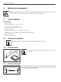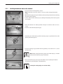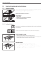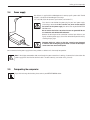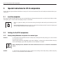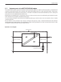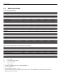
1
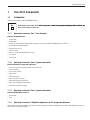
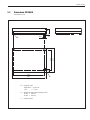
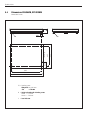
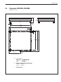
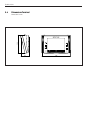
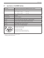
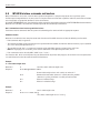
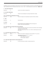
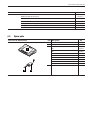
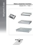
Operating Instructions Part 1 METTLER TOLEDO XP-K� Comparators ����������� XP155KS, XP604KM, XP1003KM, XP2003KL, XP6002KL Overview: XP-K Comparators 5 8 7 6 9 9 4 F 3 ME TTL 3 1 2TOL ER EDO 3 4 F 11 1 ��������� Terminal ����� (for �������� details ��� s. ���������� Operating ������������� Instructions ����� Part �� 2) 2 Display (Touch-sensitive “Touch Screen”) 3Operating keys 4 SmartSens sensors 5Type name ���� (on ���� the ������� right, ����� next ��� to ���������� the level ���������� indicator) 6 Weighing Pan 7 Centering aid 8 ������ Level ��������� indicator 9 ��������� Leveling ������ screws 10 �������������� RS232C serial ��������� interface 11 Socket for AC adapter 12���������� Connector ���� for ��������� terminal ����� cable 10 12 Contents Contents 1 Your XP-K Comparator.................................................................................................................................... 5 1.1Introduction................................................................................................................................................................. 5 1.1.1Operating Instructions Part 1, this document................................................................................................................. 5 1.1.2Operating Instructions Part 2, separate document.......................................................................................................... 5 1.1.3Operating Instructions Part 3, separate document.......................................................................................................... 5 1.1.4Operating Instructions “WeighCom Application for XP Comparator Balances”.................................................................. 5 1.2 Conventions and symbols used in these operating instructions...................................................................................... 6 1.3 Safety first.................................................................................................................................................................... 6 2 Setting up the comparator............................................................................................................................... 8 2.1 2.2 2.2.1 2.2.2 2.2.3 2.3 2.3.1 2.3.2 2.4 2.5 Standard equipment.................................................................................................................................................... 8 Setting up the comparator............................................................................................................................................ 8 Placing the terminal..................................................................................................................................................... 8 Setting the reading angle............................................................................................................................................. 8 Installing the balance cable in the terminal................................................................................................................... 9 Selecting the location and leveling the balance........................................................................................................... 10 Selecting the location................................................................................................................................................ 10 Leveling the balance.................................................................................................................................................. 10 Power supply............................................................................................................................................................. 11 Transporting the comparator....................................................................................................................................... 11 3 Special instructions for XP-K comparators...................................................................................................... 12 3.1 3.2 3.2.1 Load the comparator.................................................................................................................................................. 12 Settings for the XP-K comparators............................................................................................................................... 12 Factory setting differences compared to the standard types......................................................................................... 12 4 Cleaning and service.................................................................................................................................... 13 5 Technical data.............................................................................................................................................. 14 5.1 5.1.1 5.2 5.3 5.4 5.5 5.6 5.7 5.8 General data.............................................................................................................................................................. 14 Explanatory notes for the METTLER TOLEDO AC adapter................................................................................................ 15 Model-specific data.................................................................................................................................................... 16 Dimensions XP155KS................................................................................................................................................. 17 Dimensions XP604KM, XP1003KM.............................................................................................................................. 18 Dimensions XP2003KL, XP6002KL.............................................................................................................................. 19 Dimensions Terminal.................................................................................................................................................. 20 Specifications of the RS232C interface........................................................................................................................ 21 MT-SICS Interface commands and functions................................................................................................................ 22 6 Accessories and spare parts.......................................................................................................................... 24 6.1 6.2 Accessories............................................................................................................................................................... 24 Spare parts................................................................................................................................................................ 25 7 Index........................................................................................................................................................... 26 Your XP-K Comparator 1 Your XP-K Comparator 1.1 Introduction Thank you for choosing a METTLER TOLEDO balance. The Operating Instructions for the XP-K ����� Comparators����������������������������������������������������� ���������������������������������������������������������������� consist of 4 separate documents, whose contents are listed in the following subsections. 1.1.1 Operating Instructions Part 1, this document Contents: XP-K Comparators –Introduction – Safety notes – Setting up the comparator, Comparator assembly carried out by a METTLER TOLEDO service technician –Instructions for XP-K Comparators – Cleaning and service –Technical data –Interface commands and MT-SICS functions – Accessories – Spare parts 1.1.2 Operating Instructions Part 2, separate document Content: XP terminal, system and applications – Basic principles for using the terminal and the software – System settings – User-specific settings – Applications – Software updates – Error and status messages – Conversion table for weight units – SOP - Standard Operating Procedure –Recommended printer settings 1.1.3 Operating Instructions Part 3, separate document Content: XP adjustments and tests – Adjustments –Tests 1.1.4 Operating Instructions “WeighCom Application for XP Comparator Balances” When working with the WeighCom application, use the operating instructions “WeighCom Application for XP Comparator Balances” that were included with the delivery. Your XP-K Comparator 1.2Conventions and symbols used in these operating instructions The following conventions apply to all operating instructions: Key designations are indicated by double angular parentheses (e.g. «On/Off» or «E»). These symbols indicate safety notes and hazard warnings which, if ignored, can cause personal danger to the user, damage to the balance or other equipment, or malfunctioning of the balance. This symbol indicates additional information and notes. These make working with your balance easier, as well as ensuring that you use it correctly and economically. 1.3 Safety first Always operate and use your balance only in accordance with the instructions contained in the manuals. The instructions for setting up your new balance must be strictly observed. If the instrument is not used according to the manufacturer’s Operating Instructions (part 1, part 2, part 3 and WeighCom Application for XP Comparator Balances), protection of the instrument may be impaired. It is not permitted to use the balance in hazardous environments. Use only the AC adapter delivered with your balance, and check that the voltage printed on it is the same as your local power supply voltage. Only plug the adapter into a socket which is grounded. Do not use sharply pointed objects to operate the keyboard of your balance! Although your balance is very ruggedly constructed, it is nevertheless a precision instrument. Treat it with corresponding care. Do not open the balance: It does not contain any parts which can be maintained, repaired, or replaced by the user. If you ever have problems with your balance, contact your METTLER TOLEDO dealer. Use only balance accessories and peripheral devices from METTLER TOLEDO; they are optimally adapted to your balance. Your XP-K Comparator Disposal In conformance with the European Directive 2002/96/EC on Waste Electrical and Electronic Equipment (WEEE) this device may not be disposed of in domestic waste. This also applies to countries outside the EU, per their specific requirements. Please dispose of this product in accordance with local regulations at the collecting point specified for electrical and electronic equipment. If you have any questions, please contact the responsible authority or the distributor from which you purchased this device. Should this device be passed on to other parties (for private or professional use), the content of this regulation must also be related. Thank you for your contribution to environmental protection. Setting up the comparator 2 Setting up the comparator Note: The balance must be disconnected from the power supply when carrying out all setup and mounting work, as well as when the housing of the weighing terminal is opened during everyday operation. 2.1 Standard equipment XP-K Comparator – Weighing platform –Terminal with wall fixture and protective cover –Terminal extension cable, length = 4.5 m – AC adapter and country-specific power cable –RS232C serial interface –Operating instructions Part 1 (this document), Part 2 and Part 3 –Operating instructions “WeighCom Application for XP Comparator Balances” –Production certificate – CE declaration of conformity 2.2 Setting up the comparator Note: Your new balance will be assembled by a METTLER TOLEDO service technician. 2.2.1 Placing the terminal The terminal can either stand freely or be attached to the wall using a wall mount. F F 2.2.2 Setting the reading angle To change the reading angle, press in the two buttons (A) on the back of the terminal.The top of the terminal can then be pulled up or down until it engages in the desired position. A total of 3 setting positions are available. A A Setting up the comparator 2.2.3 Installing the balance cable in the terminal A A –Place the terminal on the operating surface. Note: Ensure that a soft, clean surface is used so as not to damage the terminal surface. –Open the housing by pressing the 2 buttons (A) for adjusting the terminal and swiveling the housing base upwards. –Pull the cable with the retaining ring (B) through the opening on the housing base (see diagram). B –Return the terminal to its normal position and open it so that the cable can be accessed. C –Insert the cable into the top housing (C). – Close both parts of the housing until the retaining ring (B) is positioned in the cable opening of the housing base. B –Place the retaining ring (B) behind the two guideways and check that it is secure (tension relief). B Note: Before closing the housing, always check that the plug is inserted correctly into the terminal plug-in connection. – Now close the housing by pressing the two buttons (A) for adjusting the terminal until the housing base engages in the top housing. A A Setting the reading angle (see Section 2.2.2) Setting up the comparator 10 2.3 Selecting the location and leveling the balance 2.3.1 Selecting the location Select a stable, vibration-free position that is as horizontal as possible. The surface must be able to safely carry the weight of a fully loaded balance. Observe ambient conditions (see Section 5.1). Avoid the following: – Direct sunlight –Powerful drafts (e.g. from fans or air conditioners) – Excessive temperature fluctuations 2.3.2 Leveling the balance If the balance is not horizontal from the beginning, it will have to be leveled during initial operation. The level is correct when the air bubble lies in the center of the level indicator (2). XP155KS, XP604KM, XP1003KM: –Level the weighing platform by turning the 4 leveling screws (1). – Ensure that the leveling screws all sit flat on the floor evenly. Test the stability of the weighing platform by pressing down on or rocking the corners. 1 2 XP2003KL, XP6002KL: –Level the weighing platform by turning the 4 leveling screws (1). –The leveling screws can be adjusted with a size 30 engineer’s wrench. – Ensure that the leveling screws all sit flat on the floor evenly. Test the stability of the weighing platform by pressing down on or rocking the corners. 2 1 Setting up the comparator 11 2.4 Power supply Your balance is supplied with an AC adapter and a country-specific power cable. The AC adapter is suitable for all line voltages in the range: 100 - 240 VAC, 50/60 Hz (for exact specifications, see Section 5.1). First, check to see whether the power plug fits your local power supply (line voltage) connection. If this is not the case, on no account connect the balance to the power supply, but contact the responsible METTLER TOLEDO dealer. Do not connect the balance to outlets that are not grounded! Do not use extension cords without PE conductors! Connect the AC adapter to the connection socket of your balance (see figure) and to the power supply. Secure the connection to your balance by screwing the plug tight. Important: Guide the cables so that they cannot become damaged or interfere with the weighing process! Take care that the AC adapter cannot come into contact with liquids! Once connected to the power supply, the balance performs a self-test and is then ready for operation. Note: If the display area remains dark, even though the power connection is working, disconnect the balance from the power supply, then check that the terminal cable is inserted correctly (see Section 2.2.3, picture 2). 2.5 Transporting the comparator If you wish to change the location, please contact your METTLER TOLEDO dealer. Special instructions for XP-K comparators 12 3 Special instructions for XP-K comparators To fully utilize the high resolution of the balance, some specific rules must be observed. These will enable you to obtain the best possible results. 3.1 Load the comparator Because of the high resolution of the balance, even minute differences of temperature or humidity can affect the result. Make sure that the weighing pan is clean and that the weighing sample is acclimatized. – Always use gloves or working aids that do not damage the weights when loading and unloading the balance. – When loading the balance you may use aids (e.g. crane) with a maximum speed of 5 mm/sec. A higher speed can have negative influences on the weighing result. 3.2 Settings for the XP-K comparators 3.2.1 Factory setting differences compared to the standard types AutoZero:Is switched off at initial operation and after a factory reset (resetting to the factory settings), but can be switched on again when required. When changing over to the “WeighCom” application, “AutoZero” is automatically switched off. When changing back to the “Weighing” application, the previous status of “AutoZero” is restored. When comparing masses, “AutoZero” must not be switched on, because it can distort the measurement values. ProFACT:Is switched off at initial operation and after a factory reset (resetting to the factory settings). When comparing masses, it is not advisable to switch “ProFACT” on. Cleaning and service 13 4 Cleaning and service Every now and then, clean the weighing pan, housing and terminal of your balance using a damp cloth. Your balance is made from high-quality, durable materials and can therefore be cleaned with a standard, mild cleaning agent. Please observe the following notes –On no account use cleaning agents, which contain solvents or abrasive ingredients, as this can result in damage to the terminal overlay. – Ensure that no liquid comes into contact with the balance, the terminal or the AC adapter. – Never open the balance or the terminal! They contain no components, which can be cleaned, repaired or replaced by the user. Please contact your METTLER TOLEDO dealer for details of the available service options. Regular servicing by an authorized service engineer ensures constant accuracy for years to come and prolongs the service life of your balance. Technical data 14 5 Technical data In this Section you will find the most important technical data for your comparator. 5.1 General data Power supply •Power supply connector 11107909 with AC/DC adapter:Primary: 100-240VAC, -15% /+10%, 50/60Hz Secondary: 12VDC ± 3%, 2.0 A (with electronic overload protection) • Cable to AC adapter: 3-core, with country-specific plug • Power supply to the balance: 12VDC ± 3%, 2.0 A, maximum ripple: 80mVDCpp Use only with a tested AC adapter with SELV output current. Ensure correct polarity Protection and standards •Overvoltage category: Class II • Degree of pollution:2 •Protection:Protected against dust and water, IP44 in use with weighing pan inserted • Standards for safety and EMC: See Declaration of Conformity (separate brochure 11780294) •Range of application: For use only in closed interior rooms Environmental conditions • Height above mean sea level: Up to 4000 m • Ambient temperature: 10 - 30 °C ± 0.7 °C / 1 h, or ± 1.0 °C / 12 h respectively •Relative air humidity: 40 at 70 % ±10 % / 4 h Materials • Weighing platform: XP155KS, XP604KM, XP1003KM: Chrome steel X5 Cr Ni 18 10, laquered and plastic XP2003KL, XP6002KL: Galvanized steel, laquered and plastic •Terminal: Die-cast zinc, chromed and plastic • Weighing pan: Chrome-nickel steel X5 Cr Ni 18 10 Technical data 15 5.1.1 Explanatory notes for the METTLER TOLEDO AC adapter The certified external power supply which conforms to the requirements for Class II double insulated equipment is not provided with a protective earth connection but with a functional earth connection for EMC puposes. This earth connection IS NOT a safety feature. Further information about conformance of our products can be found in the brochure “Declaration of Conformity” which is coming with each product or can be downloaded from www.mt.com. Consequently an earth bonding test is not required. Similarly it is not necessary to carry out an earth bonding test between the supply earth conductor and any exposed metalwork on the balance. In case of testing with regard to the directive 2001/95/CE the power supply and the balance has to be handled as Class II double insulated equipment. Because balances can be sensitive to static charges a leakage resistor, typically 10 kΩ, is connected between the earth connector and the power supply output terminals. The arrangement is shown in the figure below. This resistor is not part of the electrical safety arrangement and does not require testing at regular intervals. Equivalent circuit diagram: Plastic Housing Double Insulation P AC Input 100…240V AC N Output 12V DC DC 10 kΩ coupling resistor for electrostatic discharge E Technical data 16 5.2 Model-specific data Technical data (limit values) Model XP155KS XP604KM XP1003KM XP2003KL XP6002KL Maximum load 150 kg 600 kg 1100 kg 2500 kg 5400 kg Readability 0.05 g 0.1 g 0.5 g 1g 10 g Repeatability at nominal load (ABA, measured at) 1) 0.12 g (100 kg) 0.23 g (500 kg) 1.5 g (1000 kg) 7 g (2000 kg) 70 g (5000 kg) Repeatability at low load (ABA, measured at) 1) 0.09 g (5 kg) 0.15 g (20 kg) 1.0 g (50 kg) 4 g (100 kg) 50 g (500 kg) Repeatability absolute (Full range) 0.15 g (100 kg) 0.3 g (500 kg) 2 g (1000 kg) 10 g (2000 kg) 100 g (5000 kg) Electrical weighing range 0…150 kg 0…600 kg 0…1100 kg 0…2500 kg 0…5400 kg Taring range 150 kg 600 kg 1100 kg 2500 kg 5400 kg Pre-load with fullrange 0…125 kg 0…480 kg 0…100 kg 0…150 kg 0…440 kg Linearity (electrical weighing range) 2.0 g (100 kg) 10 g (500 kg) 20 g (1000 kg) 100 g (2000 kg) 300 g (5000 kg) Eccentric load deviation (measured at) 2) 5 g (50 kg) 40 g (200 kg) 40 g (200 kg) 120 g (1000 kg) 240 g (2000 kg) Sensitivity offset 1x10 - 5 ·Rnt 1x10 - 5 ·Rnt 1 x10 - 5 ·Rnt 1 x10 - 5 ·Rnt 1 x10 - 5 ·Rnt Sensitivity temperatur drift 3) 3 x10 -6/ºC ·Rnt 3 x10 -6/ºC ·Rnt 3 x10 -6/ºC ·Rnt 3 x10 -6/ºC ·Rnt 3 x10 -6/ºC ·Rnt Sensitivity stability 1.5 x10 /a·Rnt 1.5 x10 /a·Rnt 1.5 x10 /a·Rnt 1.5 x10 /a·Rnt 1.5 x10 -5 /a·Rnt 5s 5s 5s 5s 5s 4) -5 Settling time Weighing time, 1 ABA measurement� -5 -5 -5 36…45 s 36…45 s 36…45 s 36…45 s 36…45 s Interface update rate 23 /s 23 /s 23 /s 23 /s 23 /s Internal adjustment weights 2 2 2 2 2 Adjustment built in proFACT proFACT proFACT proFACT proFACT Measuring range of the external adjustment weights 50…150 kg 200…600 kg 200…1000 kg 500…2500 kg 1000…5000 kg Weighing platform dimensions (W x D x H) [mm] 800 x 600 x 130 1000 x 800 x 115 1000 x 800 x 115 1500 x 1250 x 182 1500 x 1250 x 182 Terminal dimensions (W x D x H) [mm] 194 x 133 x 71 194 x 133 x 71 194 x 133 x 71 194 x 133 x 71 194 x 133 x 71 Weighing pan dimensions (W x D) [mm] 800 x 600 1000 x 800 1000 x 800 1500 x 1250 1500 x 1250 Weight [kg] 54 93 93 382 382 5) Typical data for determination of the measurement uncertainty Model XP155KS XP604KM XP1003KM XP2003KL XP6002KL Repeatability at nominal load (ABA, measured at) 1) typical 0.09 g (100 kg) 0.18 g (500 kg) 1.0 g (1000 kg) 5.5 g (2000 kg) 60 g (5000 kg) Repeatability at low load (ABA, measured at) 1) typical 0.06 g (5 kg) 0.11 g (20 kg) 0.6 g (50 kg) 3.0 g (100 kg) 40 g (500 kg) Repeatability (sd) typical 0.06 g+3.2x10⁻⁷·Rgr 0.11 g+6.3x10⁻⁸·Rgr 0.6 g+4.2x10⁻⁷·Rgr 3.0 g+1.3x10⁻⁶·Rgr 40 g+4.2x10⁻⁶·Rgr Differential nonlinearity (sd) typical √5 � x10 ��� g·Rnt √5 � x10 ��� g·Rnt √5 � x10 ��� g·Rnt √ 5 x10 g·Rnt √5 � x10 ��� -12 g·Rnt Differential eccentric load deviation (sd) typical 1.2x10 · Rnt 1.2x10 · Rnt 1.2x10 · Rnt 3.3 x10 · Rnt 4.0 x10- 5· Rnt Sensitivity offset (sd) typical 2x10 · Rnt 2x10 · Rnt 2x10 · Rnt 3 x10 · Rnt 3) Minimum weight (1%, 2sd) typical Rgr =gross weight Rnt =net weight (sample weight) -12 -5 -12 -5 -6 12 g + 4.2x10 ·Rgr - 12 -5 -6 -5 -12 -5 -6 22 g + 2.4 x10 ·Rgr -5 3 x10- 6 · Rnt -6 120 g + 7.6 x10 ·Rgr -5 600 g + 2x10 ·Rgr -4 8000 g + 7.8 x10⁻⁴·Rgr sd = Standard deviation a = Year (annum) Value out of 5 ABA measurements according to OIML R111 According to OIML R76 3) In the temperature range 10…30 °C 4) Sensitivity drift/year after putting into operation for the first time, with the ProFACT self-calibration function activated 5) Weighing time without loading 1) 2) Technical data 17 Dimensions XP155KS Dimensions in mm H 5.3 503 125 724 800 FS=Leveling screw Footprint D = ∅ 35 mm Size = 17 mm H = Height adjustable with 4 leveling screws H min. = 130 mm H max. = 155 mm L =Level indicator L 600 L 35 FS Technical data 18 Dimensions XP604KM, XP1003KM Dimensions in mm H 5.4 40 FS FS 230 932 1000 1018 FS=Leveling screw �������������� Footprint D��� = ∅ 40 mm ���������� Size������ = 19 mm �� H =������� Height adjustable ����������� with ���������������� 4 leveling screws ������ H min. = 115 mm H max. = 140 mm L = Level ������ indicator ��������� 800 625 L Technical data 19 Dimensions XP2003KL, XP6002KL Dimensions in mm G H 5.5 L D FS 1360 1500 700 L FS=Leveling screw ����������������� Footprint D������ = 60 mm �������� x 60 mm �� ���������� Size������ = 30 mm �� H =������� Height adjustable ����������� ���������������� with 4 leveling screws ������ H min. = 182 mm H max. =207 mm L = Level ������ indicator ��������� 1252 1250 1140 60 60 Technical data 20 Dimensions Terminal Dimensions in mm 133 5.6 58 195 Technical data 21 5.7 Specifications of the RS232C interface Interface type: Voltage interface according to EIA RS-232C/DIN 66020 (CCITT V24/V.28) Max. cable length: 15m Signal level: Outputs:Inputs: +5V ... +15V (RL = 3 – 7kΩ) +3V ... 25V –5V ... –15V (RL = 3 – 7kΩ) –3V ... 25V Connector: Sub-D, 9-pole, female Operating mode: Full duplex Transmission mode: Bit-serial, asynchronous Transmission code: ASCII Baud rates: 600, 1200, 2400, 4800, 9600, 19200, 38400 1) (software selectable) Bits/parity: 7-bit/even, 7-bit/odd, 7-bit/none, 8-bit/none (software selectable) Stop bits: 1 stop bit Handshake: None, XON/XOFF, RTS/CTS (software selectable) End-of-line: <CR><LF>, <CR>, <LF> software selectable) Data GND Pin 2: Balance transmit line (TxD) Pin 3: Balance receive line (RxD)) 5 1 9 6 Pin 5: Ground signal (GND) Pin 7: Clear to send (hardware handshake) (CTS) Pin 8: Request to send (hardware handshake) (RTS) Handshake 1) 38400 baud is only possible in special cases, such as: • Weighing platform without terminal. Technical data 22 5.8 MT-SICS Interface commands and functions Many of the balances and scales used have to be capable of integration in a complex computer or data acquisition system. To enable you to integrate balances in your system in a simple manner and utilize their capabilities to the full, most balance functions are also available as appropriate commands via the data interface. All new METTLER TOLEDO balances launched on the market support the standardized command set “METTLER TOLEDO Standard Interface Command Set” (MT-SICS). The commands available depend on the functionality of the balance. Basic information on data interchange with the balance The balance receives commands from the system and acknowledges the command with an appropriate response. Command formats Commands sent to the balance comprise one or more characters of the ASCII character set. Here, the following must be noted: • Enter commands only in uppercase. •The possible parameters of the command must be separated from one another and from the command name by a space (ASCII 32 dec., in this description represented as /). •The possible input for “text” is a sequence of characters of the 8-bit ASCII character set from 32 dec to 255 dec. Note: For language-specific characters, please see the information in the “Operating Instructions, Part 2”. • Each command must be closed by CRLF (ASCII 13 dec., 10 dec.). The characters CRLF , which can be inputted using the Enter or Return key of most entry keypads, are not listed in this description, but it is essential they be included for communication with the balance. Example S – Send stable weight value Command S Send the current stable net weight value. Response S/S/WeightValue/Unit Current stable weight value in unit actually set under unit 1. S/I Command not executable (balance is currently executing another command, e.g. taring, or timeout as stability was not reached). S/+ Balance in overload range. S/- Balance in underload range. Command S Send a stable weight value. Response S/S/////100.00/g Example The current, stable weight value is 100.00 g Technical data 23 The MT-SICS commands listed below are the commands used most often. For additional commands and further information please refer to the Reference Manual “MT-SICS for Excellence Plus series 11780711” downloadable from the Internet under “www.mt.com”. S – Send stable weight value Command S Send the current stable net weight value. SI – Send value immediately Command SI Send the current net weight value, irrespective of balance stability. SIR – Send weight value immediately and repeat Command SIR Send the net weight values repeatedly, irrespective of balance stability. Z Zero the balance. Z – Zero Command @ – Reset Command @Resets the balance to the condition found after switching on, but without a zero setting being performed. SR – Send weight value on weight change (Send and Repeat) Command SR Send the current stable weight value and then send continuously the stable weight value after every weight change. The weight change must be at least 12.5 % of the last stable weight value, minimum = 30d. ST – Send stable weight after pressing «F» key Command ST/1 Send the current stable net weight value each time when «F» is pressed. Response ST/0 Stop sending weight value when «F» is pressed. • ST function is not active: – after switching on the balance. – after the “Reset” command. SU – Send stable weight value with currently displayed unit Command SU As the “S” command, but with the currently displayed unit. Accessories and spare parts 24 6 Accessories and spare parts 6.1 Accessories You can increase the functionality of your balance with accessories from the METTLER TOLEDO range. The following options are available: Description Part No. Printers RS-P42: Printer with connection cable RS232, for recording results 00229265 Cables for RS232C interface RS9 – RS9 (m/f), connection cable for computer or RS-P42 printer, length = 1 m 11101051 RS9 – RS25 (m/f), connection cable for computer (IBM XT or compatible), length = 2 m 11101052 RS9 – RS9 (m/m): connection cable for devices with DB9 socket (f), length = 1 m 21250066 Auxiliary displays (displays only the weight value and unit, if defined) RS/LC-BLD: Auxiliary display with RS232 & LC connection and external power supply, with table stand 00224200 RS/LC-BLDS: Auxiliary display with RS232 & LC connection for table stand or balance stand 11132630 LC-AD: Auxiliary display, active, with table stand 00229140 LC-ADS: Auxiliary display, active, with high table stand 00229150 IND690 Terminal 22011901 Input/output devices Barcode reader RS232 21900879 • AC adapter 230 V EUR 21900882 • AC adapter 115 V USA 21900883 Software MC Link; Windows® software for comparative weighing 11116504 LabX pro balance (network capable solution for management of weighing data) 11120301 LabX light balance (management of weighing data made easy) 11120317 LabX direct balance (simple data transfer) 11120340 Freeweigh. Net 21900895 Reference weights Reference weight F1 50 kg certified 00158741 Reference weight F1 100 kg certified On request Reference weight F1 500 kg certified On request Reference weight F1 1000 kg certified On request Reference weight F1 2000 kg certified On request Accessories and spare parts 25 Description Part No. Various 6.2 Protective cover for XP terminal 11132570 Draftshield XP-WKS for XP155KS 11116556 Draftshield XP-WKM for XP604KM and XP1003KM 11116557 Draftshield XP-WKL for XP2003KL and XP6002KL 11116558 LevelMatic 1000 for XP155KS and XP604KM 22001940 LevelMatic 5000 for XP1003KM, XP2003KL and XP6002KL 11116554 Spare parts Spare parts XP-K Comparators Item Designation F 1 F 3 2 No. 1 Terminal complete with software 11130837 2 AC adapter 11107909 3 Power cable DK 00087452 GB 00089405 USA 00088668 AUS 00088751 SA 00089728 EU (Schuko) 00087925 CH 00087920 I 00087457 Index 26 7 Index A M AC adapter 11, 14, 15 Accessories 24 Auxiliary display 24 Materials 14 Model-specific data 16 MT-SICS 22 B O Barcode reader 24 Overview 3 C P Cables 24 Cleaning 13 Contents: XP-K Comparators 5 Placing the terminal 8 Power supply 11, 14 Printer 24 Protection and standards 14 Protective cover 25 D Dimensions Terminal 20 Dimensions XP155KS 17 Dimensions XP2003KL, XP6002KL 19 Dimensions XP604KM, XP1003KM 18 Display area remains dark 11 Draftshield 25 E Environmental conditions 14 Equipment 8 F Factory setting differences 12 G General data 14 I Index 26 Installing the balance cable in the terminal 9 L Leveling 10 LevelMatic 25 Line voltages 11 Loading the balance 12 Load the comparator 12 R Reference weight 24 RS232C interface 21 S Selecting the location 10 Self-test 11 Service 13 Settings for the XP-K comparators 12 Setting the reading angle 8 Setting up the comparator 8 Software 24 Spare parts 25 Special instructions for XP-K comparators 12 T Terminal 8 Transport 11 To protect your METTLER TOLEDO product’s future: METTLER TOLEDO Service assures the quality, measuring accuracy and preservation of value of all METTLER TOLEDO products for years to come. Please send for full details about our attractive terms of service. Thank you. *11781049* Mettler-Toledo AG Laboratory & Weighing Technologies CH-8606 Greifensee, Switzerland Subject to technical changes © Mettler-Toledo AG 2009 11781049 A 0910/2.12 www.mt.com For more information GWP® Good Weighing Practice™ The global weighing guideline GWP ® reduces risks associated with your weighing processes and helps to • choose the appropriate balance • reduce costs by optimizing testing procedures • comply with the most common regulatory requirements www.mt.com/GWP